EP3901378B1 - Schnellkupplung mit zentriervorrichtung - Google Patents
Schnellkupplung mit zentriervorrichtung Download PDFInfo
- Publication number
- EP3901378B1 EP3901378B1 EP21164528.8A EP21164528A EP3901378B1 EP 3901378 B1 EP3901378 B1 EP 3901378B1 EP 21164528 A EP21164528 A EP 21164528A EP 3901378 B1 EP3901378 B1 EP 3901378B1
- Authority
- EP
- European Patent Office
- Prior art keywords
- coupling part
- coupling
- energy
- quick coupling
- quick
- Prior art date
- Legal status (The legal status is an assumption and is not a legal conclusion. Google has not performed a legal analysis and makes no representation as to the accuracy of the status listed.)
- Active
Links
Images


Classifications
-
- E—FIXED CONSTRUCTIONS
- E02—HYDRAULIC ENGINEERING; FOUNDATIONS; SOIL SHIFTING
- E02F—DREDGING; SOIL-SHIFTING
- E02F3/00—Dredgers; Soil-shifting machines
- E02F3/04—Dredgers; Soil-shifting machines mechanically-driven
- E02F3/96—Dredgers; Soil-shifting machines mechanically-driven with arrangements for alternate or simultaneous use of different digging elements
-
- E—FIXED CONSTRUCTIONS
- E02—HYDRAULIC ENGINEERING; FOUNDATIONS; SOIL SHIFTING
- E02F—DREDGING; SOIL-SHIFTING
- E02F3/00—Dredgers; Soil-shifting machines
- E02F3/04—Dredgers; Soil-shifting machines mechanically-driven
- E02F3/28—Dredgers; Soil-shifting machines mechanically-driven with digging tools mounted on a dipper- or bucket-arm, i.e. there is either one arm or a pair of arms, e.g. dippers, buckets
- E02F3/36—Component parts
- E02F3/3604—Devices to connect tools to arms, booms or the like
- E02F3/3609—Devices to connect tools to arms, booms or the like of the quick acting type, e.g. controlled from the operator seat
- E02F3/3654—Devices to connect tools to arms, booms or the like of the quick acting type, e.g. controlled from the operator seat with energy coupler, e.g. coupler for hydraulic or electric lines, to provide energy to drive(s) mounted on the tool
-
- E—FIXED CONSTRUCTIONS
- E02—HYDRAULIC ENGINEERING; FOUNDATIONS; SOIL SHIFTING
- E02F—DREDGING; SOIL-SHIFTING
- E02F3/00—Dredgers; Soil-shifting machines
- E02F3/04—Dredgers; Soil-shifting machines mechanically-driven
- E02F3/28—Dredgers; Soil-shifting machines mechanically-driven with digging tools mounted on a dipper- or bucket-arm, i.e. there is either one arm or a pair of arms, e.g. dippers, buckets
- E02F3/36—Component parts
- E02F3/3604—Devices to connect tools to arms, booms or the like
- E02F3/3609—Devices to connect tools to arms, booms or the like of the quick acting type, e.g. controlled from the operator seat
- E02F3/3663—Devices to connect tools to arms, booms or the like of the quick acting type, e.g. controlled from the operator seat hydraulically-operated
Definitions
- the present invention relates to a quick coupling for coupling a tool to the boom of a working device according to the preamble of claim 1 and to a working device with such a quick coupling.
- Swivel-type quick couplings are widely used on certain work equipment such as hydraulic excavators, as they allow for easy and quick changing of different tools such as hydraulic grapples, excavation buckets, grabs and the like.
- This can advantageously be a cross bolt that is hooked into a hook-shaped eyelet on the opposite quick coupling part.
- the boom-side quick coupling part can then be swiveled relative to the tool about the already engaged locking axis in order to find the locking position in which the second locking axis can be locked.
- the latter is usually formed by a pair of locking bolts that can move apart from one another and into corresponding locking holes on the opposite quick coupling part.
- such quick couplings can have a power circuit coupling or hydraulic coupling, with each of the quick coupling parts having a corresponding power coupling part, which pivot together with the quick coupling parts and are automatically brought together.
- mount one of the two power coupling parts usually the tool-side power coupling part, in a movable manner, for example on an arrangement of compression springs.
- this often results in an unclean coupling, which can lead to oil leakage.
- EP 1 239 087 A1 proposed to provide a linear guide for the energy coupling parts, which forces them to move linearly relative to one another along a straight line, contrary to the circular pivoting movement.
- the linear guide has guide elements on the boom and tool-side energy coupling parts that interact during coupling, which can be designed, for example, as guide bolts and holes that engage with one another before the connection connectors are brought together and cause an exactly linear relative movement.
- FIG. 1 An example of such a problematic installation position is the use of such a quick coupling on a wheel loader.
- the installation orientation of the tool-side power coupling part is vertical, i.e. the straight coupling of the power coupling parts mediated by the linear guide takes place along an essentially horizontal line. Due to the weight of the movable power coupling part, it pivots out of the central position due to gravity, so that the guide elements or guide bolts and holes are no longer aligned with one another. The deflection of the movable power coupling part makes coupling or engaging the guide elements difficult or even impossible. This can lead to increased wear or damage if the coupling is carried out using force to overcome the offset.
- the present invention is therefore based on the object of overcoming this disadvantage and enabling the use of such a quick coupling regardless of the installation position and situation of the energy coupling parts.
- the quick coupling according to the invention which is provided for coupling a tool to the boom of a working device, in particular a wheel loader, comprises a boom-side and a tool-side quick coupling part and a power circuit coupling for automatically coupling a tool-side power connection to a boom-side power connection.
- the quick coupling parts can be reversibly locked to one another via a pair of spaced-apart locking axes.
- the energy circuit coupling comprises a boom-side and a tool-side energy coupling part, which are arranged on the two quick-coupling parts in such a way that they move towards each other on a circular path around the first locking axis by pivoting the two quick-coupling parts together about a first of the two locking axes and thereby automatically
- At least one of the two energy coupling parts hereinafter referred to as the movable energy coupling part, is mounted so as to be pivotable about an axis parallel to the first locking axis and movable or displaceable perpendicular to it.
- the energy circuit coupling comprises a linear guide which is designed, in cooperation with the movable bearing of the movable energy coupling part, to compensate for the relative movement of the two energy coupling parts along a circular path when the quick coupling parts are pivoted together and to guide the two energy coupling parts linearly, i.e. along a straight line, towards each other when coupling.
- the quick coupling additionally comprises a centering device, by means of which the movable energy coupling part can be held in a central position regardless of its spatial alignment or orientation and a movement of the movable energy coupling part relative to the quick coupling part attached thereto can be prevented in the absence of an external force.
- the centering device is designed to enable a movement of the movable energy coupling part relative to the quick coupling part attached thereto during automatic coupling with the other energy coupling part due to an external force generated by the coupling process.
- an external force is any force that does not result from the weight of the movable energy coupling part or that is permanently applied to it due to the storage/fastening/connection of the movable energy coupling part with cables, hoses, etc.
- An external force in the sense of the present invention is in particular a force that is generated by the coupling with the other energy coupling part when the two quick coupling parts are brought together and acts on the movable energy coupling part.
- the centering device ensures that the movable energy coupling part does not move from the central position intended for a smooth coupling due to its own weight, the connection of hoses or the like, regardless of the installation position or spatial orientation of the movable energy coupling part. This makes it possible, for example, to mount the movable energy coupling part vertically on the quick coupling part of a wheel loader bucket without it swinging downwards due to gravity and making coupling of the energy coupling parts difficult or impossible.
- the centering device is designed to enable movement of the movable energy coupling part - within certain limits - only when an external force in the sense defined above acts on it, i.e. in particular a force generated by the coupling process when the movable energy coupling part is contacted by the other energy coupling part.
- the quick coupling according to the invention can be used in any installation position and independently of the connection to other components such as hoses, which significantly expands the application possibilities.
- the present invention not only opens up further application possibilities with installation positions that differ from the previous situation on hydraulic excavators.
- the quick coupling according to the invention with centering device can also be used advantageously on hydraulic excavators with installation positions that are unproblematic in terms of their own weight, namely in particular in cases in which a hose layout is used that leads to the movable energy coupling part tipping over due to the inherent or pre-stressed nature of the hoses.
- the quick coupling according to the invention is preferably a quick coupling according to the EP 1 239 087 A1 , which additionally has the centering device according to the invention.
- the disclosure of the EP 1 239 087 A1 is explicitly included in the present teaching.
- the quick coupling according to the invention can be used in accordance with any of the EP 1 239 087 A1 described advantageous embodiments, or according to any combination of the embodiments disclosed therein.
- the EP 1 239 087 A1 The embodiments described are therefore also possible embodiments of the present quick coupling according to the invention.
- the quick coupling according to the invention can be, for example, a quick coupling for coupling a tool to the boom of a hydraulic excavator and the like, with a boom-side quick coupling part and a tool-side quick coupling part, which can be locked together via a pair of spaced locking axes, such that after locking only a first of the two locking axes, the two quick coupling parts can be pivoted together about the said first locking axis and then the second locking axis can be locked, as well as a power circuit coupling, in particular a hydraulic coupling, for automatically coupling a tool-side power connection to a boom-side power connection, wherein the power circuit coupling has a boom-side power coupling part and a tool-side power coupling part, which are arranged on the boom-side quick coupling part and the tool-side quick coupling part at a distance from the first locking axis in such a way that they can be pivoted together by pivoting the two quick coupling parts about the first Locking axis
- the centering device comprises at least one centering element which is fixedly or immovably mounted on the quick coupling part and, in the absence of an external force, holds the movable energy coupling part in the central position in a force-locking and/or positive-locking manner.
- the movable energy coupling part can be fixed in place by means of the centering element in a form-locking or a force-locking manner, for example in a form-locking manner in certain directions and in other directions.
- the movable energy coupling part is mounted on the quick coupling part via a spring device, in particular an arrangement of one or more compression springs, which presses the movable energy coupling part against the centering element and thereby holds it in the central position or - in particular immediately after the removal of a spring device -
- the spring device generates a contact force on the centering element which holds the movable energy coupling part in the correct position, i.e. the spring device is pre-tensioned in the central position.
- the spring force or contact force must be large enough that the movable energy coupling part is not moved from the central position by its own weight or the internal stresses of possible connecting hoses in any of the possible installation positions.
- the centered movable energy coupling part must therefore have a certain degree of mobility when an external force is applied which exceeds its own weight/hose stresses etc.
- the centering device has at least one holding element arranged on the movable energy coupling part, which is designed to interact with the at least one centering element in a force-fitting and/or form-fitting manner.
- the at least one holding element is thus movably mounted on the quick coupling part together with the movable energy coupling part and is pressed against the at least one centering element in particular by the spring device.
- the holding element comprises a recess into which the centering element is at least partially received or retracted in the central position.
- the holding element can itself be the recess or can comprise additional parts.
- the recess has at least one bevel and/or rounding, which interacts with at least one bevel and/or rounding of the centering element.
- the recess is funnel-shaped at least along one direction, wherein the centering element is beveled and/or rounded at least along that same direction and is preferably bolt-shaped.
- the recess can therefore be beveled and/or rounded along at least one direction, so that a funnel shape results in a corresponding cross-sectional view.
- the centering element which is located in the central position partially within the recess, can move along the bevels when an external force is applied in order to enable movement of the movable energy coupling part during coupling.
- a bolt-shaped shape of the centering element i.e. rounded in the direction of the funnel-shaped design, is advantageous here.
- the funnel-shaped design and the preferably bolt-shaped rounding should be formed at least in a plane that is perpendicular to the axis around which the movable energy coupling part is pivoted during the coupling process.
- This axis is preferably perpendicular to the straight line along which the linear joining of the energy coupling parts takes place via the linear guide.
- the bevels can also have an angle of 20-70°, in particular of 25-45°.
- the recess has a particularly continuous recess.
- the continuous recess is therefore open, ie it passes through the component of the movable energy coupling part in which the recess is formed.
- the recess is preferably smaller than the centering element.
- This recess has the function of forming an opening within the recess so that no deposits or dirt can accumulate within the recess, which would prevent the centering element from being positioned correctly. The accumulations pass out of the recess through the recess or are pushed into the recess by the centering element.
- the recess can be a hole or a slot, for example, and is preferably arranged at the lowest point or bottom of the recess.
- the centering element can also have a recess on the side facing the recess, into which dirt accumulating in the recess can be forced so that the recess does not become clogged. This can also be continuous.
- the movable energy coupling part is mounted on the quick coupling part attached thereto via two spaced-apart support elements and is preferably arranged between the support elements, wherein each of the support elements has a centering element.
- the support elements can be plate-shaped and extend essentially perpendicularly from the quick coupling part.
- the movable energy coupling part can be mounted on the support elements via a spring bearing.
- the support elements are in particular rigidly connected to the quick coupling part and partially enclose the movable energy coupling part.
- the centering elements are bolt-shaped and each interact with a holding element as described above.
- the holding elements are preferably formed on or in a carrier block of the movable energy coupling part, which extends essentially between and perpendicular to the carrier elements.
- the carrier block can have one or more connector pieces that form the energy connection of the movable energy coupling part.
- the recesses are formed on the top side of the carrier block facing away from the quick coupling part, in particular on the edges or sides that are adjacent to the carrier elements.
- Such a design is particularly easy to implement, since the recesses forming the holding elements are only introduced laterally on the top side of the carrier block - for example by milling and/or drilling - and the bolt-shaped centering elements are at the corresponding points or at the corresponding distance from the Quick coupling parts must be attached - for example screwed - to the inner surfaces of the support elements.
- the bolt-shaped centering elements are conical and are attached to the support elements via the narrower ends.
- the beveling/rounding of the conical shape of the centering elements enables deposits or dirt that may have accumulated in the recesses to be displaced from the recesses, so that the centering elements can be correctly positioned in the recesses.
- the recesses are preferably open towards the sides of the support block, so that dirt/deposits can be forced out of the recesses by the conical shape of the centering elements.
- each of the carrier elements having at least two centering elements.
- the at least two centering elements provided on each side one is preferably connected to the carrier element via a fixed bearing and the other via a loose bearing, thus forming a fixed-loose arrangement, i.e. the centering element connected via the loose bearing is not rigidly attached to the carrier element, but is movably mounted so that a certain relative mobility is provided between the two centering elements.
- the energy connection of the movable energy coupling part is arranged on the side of the carrier block facing away from the movable bearing on the quick coupling part and is designed in such a way that when coupling with the other energy coupling part, a coupling with the other energy connection arranged thereon is automatically established for producing an energy circuit connection is established.
- the energy connection can comprise one or more connector pieces which can be pushed together or connected with corresponding connector pieces of the other energy coupling part and bring about the corresponding energy connection (e.g. hydraulic fluid connection).
- the connector pieces extend in particular vertically away from the carrier block and can be known connector pieces of female and male type. In this sense, the carrier block can also be referred to as a connector block.
- the movable energy coupling part is arranged on the tool-side quick coupling part of a tool, in particular a wheel loader bucket, and is preferably aligned in such a way that the coupling of the energy coupling parts mediated by the linear guide takes place along a substantially horizontal line.
- the movable energy coupling part is therefore rotated approximately 90° to the usual installation position used on the hydraulic excavator. Without the centering device according to the invention, the movable energy coupling part would be tilted out of the central position required for the smooth coupling procedure due to its own weight, the hose tensions and the movable bearing.
- the linear guide preferably comprises at least two guide pins on one energy coupling part and associated guide holes on the other energy coupling part, into which the said guide pins move when the two energy coupling parts move together. They force the spring device to deflect in order to compensate for the pivoting movement component.
- the guide pins are rigidly connected to the carrier block and protrude vertically over it towards the opposite energy coupling part.
- Each guide pin is preferably essentially cylindrical and has a rounded head, which prevents it from jamming when inserted into the guide holes. It can also be provided that the holding elements/recesses in the carrier block are aligned or in a line with the guide pins/guide holes of the linear guide.
- the present invention further relates to a working device, in particular a wheel loader, with a quick coupling according to the invention.
- a working device in particular a wheel loader
- a quick coupling according to the invention This obviously results in the same advantages and properties as for the quick coupling according to the invention, which is why a repeated description is omitted at this point.
- the above statements regarding the possible designs of the quick coupling according to the invention therefore apply accordingly.
- the preferred embodiment of the quick coupling according to the invention discussed below is essentially a quick coupling according to the EP 1 239 087 A1 , whereby a centering device is additionally provided, which is described in detail below.
- Those elements and properties of the quick coupling according to the invention which are not explicitly described below preferably correspond to one of the EP 1 239 087 A1 disclosed embodiments.
- the quick coupling according to the invention comprises a boom-side and a tool-side quick coupling part, which can be reversibly locked to one another via a pair of spaced, parallel locking axes.
- the quick coupling has a power circuit coupling comprising a tool-side power coupling part attached to the tool-side quick coupling part and a boom-side power coupling part attached to the boom-side quick coupling part.
- the tool-side power coupling part is movably mounted on the quick coupling part via a spring device 16 and is referred to below as the movable power coupling part 10.
- the other power coupling part attached to the boom-side quick coupling part is not movably mounted in this embodiment, although this is not mandatory.
- the other power coupling part could therefore also be movably mounted in one embodiment.
- the energy coupling parts each have an energy connection 12, which comprises several connector pieces 13, each of which is arranged on a support block 18 and protrudes perpendicularly from it.
- an energy circuit connection is closed, in particular a hydraulic connection for supplying a hydraulic tool with hydraulic oil.
- This can be, for example, a wheel loader bucket with hydraulic components.
- the energy coupling parts also have a linear guide 14, which forces the energy coupling parts to move relative to one another along a line or straight line, counter to the circular pivoting movement around one of the two locking axes.
- the linear guide comprises two parallel guide bolts 14, which are attached to the carrier lock 18 of the movable energy coupling part 10 and protrude perpendicularly therefrom, as well as corresponding guide holes on the other energy guide part, into which the guide bolts 14 move during coupling and force the linear coupling movement before the connector pieces 13 engage with one another.
- the movable energy coupling part 10 of the quick coupling according to the invention is shown in a perspective view, whereby the quick coupling part attached to it is hidden for reasons of clarity.
- the movable energy coupling part 10 comprises a substantially plate-shaped carrier block 18, which is movably mounted on the quick coupling part on a spring device 16 comprising four compression springs.
- Several connector pieces 13 and two guide bolts 14 of the linear guide are arranged on the carrier block 18, which protrude parallel from the surface of the carrier block 18 opposite the spring device 16.
- two pressure tappets 17 are arranged on the side of the spring device 16, the function of which is in the EP 1 239 087 A1 described.
- the movable energy coupling part 10 is mounted on two lateral support elements 30, which are rigidly connected to the quick coupling part.
- the support elements 30 are shown individually in a perspective view in the Figure 2 They are plate-shaped, differ in shape from one another and are aligned parallel to one another.
- the carrier elements 30 are arranged at a distance from one another so that the carrier block 18 is mounted between them, which is mounted via the spring device 16 on two fastenings 32 which are formed or mounted on the inner sides of the carrier elements 30.
- the pressure tappets 17 are also mounted on the fastenings 32.
- the support block 18 and the positions of the components arranged thereon are axially symmetrical. In plan view, it has a substantially rectangular basic shape and extends substantially vertically between the support elements 30. The short sides of the support block 18 rest against the support elements 30.
- a centering element 20 is mounted on the inside of each carrier element 30, in the present embodiment via a screw connection. Furthermore, the carrier block 18 has two recesses 24 on the side in the area of the edges, which form the holding elements 22, which interact with the centering elements 20 and together with them form the centering device according to the invention.
- the centering elements 20 are rigidly connected to the quick coupling part via the carrier elements 30, while the holding elements 22 are movably mounted due to the spring-loaded mounting of the carrier block 18 and are movable relative to the centering elements 20.
- the Figure 3 shows the movable energy coupling part 10 together with the support elements 30 on which it is mounted in a plan view.
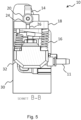
- a frontal cross-sectional view along the line AA is shown in the Figure 4 and a side cross-sectional view along the line BB in the Figure 5 shown.
- the centering elements 20 are attached to the carrier elements 30 at such a distance from the fastenings 32 that the carrier block 18 is pressed against the centering elements 20 by the spring device 16.
- This pressing force holds the carrier block 18 or the movable energy coupling part 10 in a defined position, which is referred to here as the central position.
- the guide pins 14 can be correctly and jam-freely threaded into the corresponding guide holes of the other energy coupling part (not shown) during the coupling process.
- the pressing holds the movable energy coupling part 10 in the central position even if the carrier block 18 is not oriented essentially horizontally. is (as is the case, for example, in the EP 1 239 087 A1 the case), but has a different, in particular vertical, installation position.
- the contact pressure is dimensioned such that in no installation position does the movable energy coupling part 10 move from the central position due to its own weight and/or the rigidity/inherent stress of the hoses (not shown) connected to it via the hose connections 11. This makes the quick coupling according to the invention particularly suitable for use on a wheel loader bucket.
- the recesses 24 are funnel-shaped and the centering elements 20 are designed as round bolts.
- the recesses 24 have a rectangular or slotted shape in plan view and are tapered conically towards the center along the short sides of the carrier block 18.
- the bevels have an angle of approximately 30°, although other angles are also possible.
- the bevels merge into a rectangular recess 26 which runs through the entire carrier block 18 and opens into the underside of the carrier block 18.
- the recesses 24 are also open on the sides of the short sides of the carrier block 18, i.e. towards the carrier elements 30.
- the centering elements 20 are designed as conical bolts with a circular cross-section, which are attached to the support elements 30 via the short side. In the central position, the centering elements 20 are partially accommodated in the recesses 24 (cf. Figures 4 and 5 ).
- the bevels enable movement of the carrier block 18, in particular pivoting or tilting about a pivot axis parallel to the first locking axis and/or displacement, relative to the centering elements 20 by external forces occurring during the coupling process.
- the carrier block 18 or the movable energy coupling part 10 is thus held in the central position by the centering elements 20 in a form-fitting manner in the direction of the coupling line defined by the linear guide 14 and in a force-fitting manner in a direction perpendicular thereto.
- the contact force by the spring device 16 is set in such a way that the mobility of the carrier block 18 is ensured when an external force occurs as a result of the coupling process. If the carrier block 18 is deflected from the central position by such an external force and this external force disappears, the movable energy coupling part 10 is moved or pressed back into the central position by the spring device 16.
- the compression springs of the spring device 16 are not evenly compressed in the central position and are not aligned parallel to one another.
- the centering elements 20 are also not arranged centrally above the carrier block 18, but slightly offset to the side, namely on the straight line connecting the guide pins 14. However, other arrangements of the centering elements 20 are also possible, for example an arrangement in which they are not aligned with the guide pins 14.
- the recesses 26 in the cutouts 24 prevent dirt or deposits from accumulating in the cutouts 24 and blocking them, which would prevent correct positioning of the movable energy coupling part 10.
- the deposits are pressed into the cutouts 26 by the centering elements 20 and are thereby forced out of the cutouts 24.
- the conical shape of the centering elements 20 ensures that dirt or deposits are forced outwards from the sides of the cutouts 24. As a result, the cutouts 24 always remain free of dirt, which ensures correct positioning in the central position.
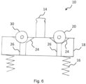
- the Figure 6 shows a further embodiment of the movable energy coupling part 10 of the quick coupling according to the invention in a side view looking at the short side of the carrier block 18.
- the carrier block 18 has two funnel-shaped recesses 24 on each short side.
- the two centering elements 20 of each carrier element 30 form a Fixed-loose arrangement, wherein one of the centering elements 20 is connected to the quick coupling part or carrier element 30 via a fixed bearing and the other via a loose bearing.
- the use of more than two centering elements 20 per side / carrier element 30 is also conceivable.
- a rotatable bearing of one or more centering elements 20 on the carrier elements 30 could also be provided.
Landscapes
- Engineering & Computer Science (AREA)
- Mechanical Engineering (AREA)
- Mining & Mineral Resources (AREA)
- Civil Engineering (AREA)
- General Engineering & Computer Science (AREA)
- Structural Engineering (AREA)
- Quick-Acting Or Multi-Walled Pipe Joints (AREA)
- Shovels (AREA)
Priority Applications (1)
| Application Number | Priority Date | Filing Date | Title |
|---|---|---|---|
| SI202130306T SI3901378T1 (sl) | 2020-04-17 | 2021-03-24 | Hitra spojka z napravo za centriranje |
Applications Claiming Priority (1)
| Application Number | Priority Date | Filing Date | Title |
|---|---|---|---|
| DE102020110523.1A DE102020110523A1 (de) | 2020-04-17 | 2020-04-17 | Schnellkupplung mit Zentriervorrichtung |
Publications (2)
| Publication Number | Publication Date |
|---|---|
| EP3901378A1 EP3901378A1 (de) | 2021-10-27 |
| EP3901378B1 true EP3901378B1 (de) | 2025-02-12 |
Family
ID=75203163
Family Applications (1)
| Application Number | Title | Priority Date | Filing Date |
|---|---|---|---|
| EP21164528.8A Active EP3901378B1 (de) | 2020-04-17 | 2021-03-24 | Schnellkupplung mit zentriervorrichtung |
Country Status (8)
| Country | Link |
|---|---|
| US (1) | US11970833B2 (pl) |
| EP (1) | EP3901378B1 (pl) |
| JP (1) | JP7667688B2 (pl) |
| CN (1) | CN113529838B (pl) |
| DE (1) | DE102020110523A1 (pl) |
| ES (1) | ES3024369T3 (pl) |
| PL (1) | PL3901378T3 (pl) |
| SI (1) | SI3901378T1 (pl) |
Families Citing this family (2)
| Publication number | Priority date | Publication date | Assignee | Title |
|---|---|---|---|---|
| DE102022126522A1 (de) | 2022-10-12 | 2024-04-18 | Liebherr-France Sas | Arbeitsmaschine mit Kupplungsvorrichtung für fluidführende Leitungen |
| DE102022127836A1 (de) | 2022-10-21 | 2024-05-02 | Liebherr-Hydraulikbagger Gmbh | Baggerlöffel |
Citations (1)
| Publication number | Priority date | Publication date | Assignee | Title |
|---|---|---|---|---|
| US20160326712A1 (en) * | 2015-05-04 | 2016-11-10 | Deere & Company | Quick coupler having spring applied, hydraulically released primary and secondary lock members mounted on same cross shaft |
Family Cites Families (11)
| Publication number | Priority date | Publication date | Assignee | Title |
|---|---|---|---|---|
| JPS52101801A (en) * | 1976-02-24 | 1977-08-26 | Caterpillar Mitsubishi Ltd | Quick coupler |
| DE4214569C2 (de) * | 1992-05-08 | 2001-12-20 | Lehnhoff Hartstahl Gmbh & Co | Schnellwechselvorrichtung |
| PL200100B1 (pl) | 2001-03-09 | 2008-12-31 | Liebherr Hydraulikbagger | Szybkozłącze |
| DE102004037459A1 (de) | 2004-08-02 | 2006-02-23 | Liebherr-Hydraulikbagger Gmbh | Hydraulikschnellkupplung |
| DE102006023420B4 (de) * | 2006-05-17 | 2013-02-28 | Lehnhoff Hartstahl Gmbh & Co. Kg | Schnellwechselvorrichtung |
| US7984575B2 (en) * | 2007-07-05 | 2011-07-26 | Caterpillar Inc. | Quick coupler assembly |
| US7686563B2 (en) | 2007-08-23 | 2010-03-30 | 1708828 Ontario Ltd. O/A Horst Welding | Coupling apparatus for releasably coupling hydraulically powered work implements to a work vehicle |
| AT506554B1 (de) * | 2008-03-20 | 2011-11-15 | Alois Ing Wimmer | Kupplungsvorrichtung mit einer einrichtung zum automatischen verbinden von energieleitungen |
| US9357690B2 (en) * | 2014-10-22 | 2016-06-07 | Deere & Company | Tractor-implement coupling mechanism |
| FR3072981B1 (fr) | 2017-10-26 | 2021-03-19 | Groupe Mecalac | Dispositif de connexion automatique entre un outil et un porte-outil d'engin de chantier ou de travaux publics |
| KR102086686B1 (ko) * | 2018-08-09 | 2020-03-09 | 장정수 | 굴삭기용 어태치먼트 결합링크 |
-
2020
- 2020-04-17 DE DE102020110523.1A patent/DE102020110523A1/de active Pending
-
2021
- 2021-03-24 ES ES21164528T patent/ES3024369T3/es active Active
- 2021-03-24 SI SI202130306T patent/SI3901378T1/sl unknown
- 2021-03-24 PL PL21164528.8T patent/PL3901378T3/pl unknown
- 2021-03-24 EP EP21164528.8A patent/EP3901378B1/de active Active
- 2021-04-15 JP JP2021068898A patent/JP7667688B2/ja active Active
- 2021-04-16 CN CN202110414384.1A patent/CN113529838B/zh active Active
- 2021-04-16 US US17/233,363 patent/US11970833B2/en active Active
Patent Citations (1)
| Publication number | Priority date | Publication date | Assignee | Title |
|---|---|---|---|---|
| US20160326712A1 (en) * | 2015-05-04 | 2016-11-10 | Deere & Company | Quick coupler having spring applied, hydraulically released primary and secondary lock members mounted on same cross shaft |
Also Published As
| Publication number | Publication date |
|---|---|
| US20210324600A1 (en) | 2021-10-21 |
| ES3024369T3 (en) | 2025-06-04 |
| CN113529838A (zh) | 2021-10-22 |
| JP2021175870A (ja) | 2021-11-04 |
| CN113529838B (zh) | 2025-10-31 |
| DE102020110523A1 (de) | 2021-10-21 |
| JP7667688B2 (ja) | 2025-04-23 |
| PL3901378T3 (pl) | 2025-09-08 |
| US11970833B2 (en) | 2024-04-30 |
| SI3901378T1 (sl) | 2025-07-31 |
| EP3901378A1 (de) | 2021-10-27 |
Similar Documents
| Publication | Publication Date | Title |
|---|---|---|
| EP1624116B1 (de) | Hydraulikschnellkupplung | |
| EP2018456B1 (de) | Schnellwechselvorrichtung | |
| DE4214569C1 (de) | Schnellwechselvorrichtung | |
| EP1239087B1 (de) | Schnellkupplung | |
| DE102014116245B4 (de) | Schnellwechseleinrichtung einer Arbeitsmaschine | |
| EP3901378B1 (de) | Schnellkupplung mit zentriervorrichtung | |
| DE102005037105C5 (de) | Adapter für ein Arbeitsgerät als Teil einer Schnellwechselvorrichtung und Schnellwechselvorrichtung | |
| DE202019101747U1 (de) | Schnellwechsler für Baumaschinenwerkzeuge | |
| EP2159333B1 (de) | Energieträgerkupplung, sowie Kupplung mit Energieträgerkupplung | |
| EP1522635B1 (de) | Schnellwechselkupplung zur Befestigung der Arbeitswerkzeuge an einem Baggerausleger | |
| WO2019048602A1 (de) | Steckverbinder mit verriegelungshaken zur festlegung seines kontaktträgers in seinem aussengehäuse | |
| EP2902582B1 (de) | Mastanordnung und Verfahren zum Verbinden einer Werkzeugeinheit mit einem Mastschlitten einer Mastanordnung | |
| EP1251016A2 (de) | Anhängerkupplung für ein Fahrzeug, insbesondere für einen Ackerschlepper | |
| EP3699362B1 (de) | Kupplungssystem zum auswechselbaren kuppeln eines anbaugeräts mit einer arbeitsmaschine | |
| EP3243008B1 (de) | Verbindungsbeschlag | |
| EP3095559B1 (de) | Drehmomentschrauber-system | |
| DE3514167C2 (pl) | ||
| EP1458938B1 (de) | Frontlader mit einer automatischen kupplungsvorrichtung | |
| EP0429567A1 (de) | Vorrichtung zur lösbaren kupplung von greifern oder entsprechenden werkzeugen an roboterarmen. | |
| EP3800299A1 (de) | Arbeitsgerät, insbesondere radlader | |
| DE102020100519A1 (de) | Ladekranwechsler | |
| EP4357538A1 (de) | Baggerlöffel | |
| EP1651818A1 (de) | Anordnung zum auswechselbaren befestigen eines anbauteiles, z.b. einer baggerschaufel, an einem baggerausleger oder einem fahrzeug | |
| DE4111522C2 (de) | Wechselsystem für Werkzeuge an Bediengeräten | |
| EP4453327B1 (de) | Schnellwechsler |
Legal Events
| Date | Code | Title | Description |
|---|---|---|---|
| PUAI | Public reference made under article 153(3) epc to a published international application that has entered the european phase |
Free format text: ORIGINAL CODE: 0009012 |
|
| STAA | Information on the status of an ep patent application or granted ep patent |
Free format text: STATUS: THE APPLICATION HAS BEEN PUBLISHED |
|
| AK | Designated contracting states |
Kind code of ref document: A1 Designated state(s): AL AT BE BG CH CY CZ DE DK EE ES FI FR GB GR HR HU IE IS IT LI LT LU LV MC MK MT NL NO PL PT RO RS SE SI SK SM TR |
|
| B565 | Issuance of search results under rule 164(2) epc |
Effective date: 20210927 |
|
| STAA | Information on the status of an ep patent application or granted ep patent |
Free format text: STATUS: REQUEST FOR EXAMINATION WAS MADE |
|
| 17P | Request for examination filed |
Effective date: 20220426 |
|
| STAA | Information on the status of an ep patent application or granted ep patent |
Free format text: STATUS: EXAMINATION IS IN PROGRESS |
|
| 17Q | First examination report despatched |
Effective date: 20231221 |
|
| GRAP | Despatch of communication of intention to grant a patent |
Free format text: ORIGINAL CODE: EPIDOSNIGR1 |
|
| STAA | Information on the status of an ep patent application or granted ep patent |
Free format text: STATUS: GRANT OF PATENT IS INTENDED |
|
| INTG | Intention to grant announced |
Effective date: 20241028 |
|
| GRAS | Grant fee paid |
Free format text: ORIGINAL CODE: EPIDOSNIGR3 |
|
| GRAA | (expected) grant |
Free format text: ORIGINAL CODE: 0009210 |
|
| STAA | Information on the status of an ep patent application or granted ep patent |
Free format text: STATUS: THE PATENT HAS BEEN GRANTED |
|
| AK | Designated contracting states |
Kind code of ref document: B1 Designated state(s): AL AT BE BG CH CY CZ DE DK EE ES FI FR GB GR HR HU IE IS IT LI LT LU LV MC MK MT NL NO PL PT RO RS SE SI SK SM TR |
|
| REG | Reference to a national code |
Ref country code: GB Ref legal event code: FG4D Free format text: NOT ENGLISH |
|
| REG | Reference to a national code |
Ref country code: CH Ref legal event code: EP |
|
| REG | Reference to a national code |
Ref country code: DE Ref legal event code: R096 Ref document number: 502021006594 Country of ref document: DE |
|
| REG | Reference to a national code |
Ref country code: IE Ref legal event code: FG4D Free format text: LANGUAGE OF EP DOCUMENT: GERMAN Ref country code: NL Ref legal event code: FP |
|
| PGFP | Annual fee paid to national office [announced via postgrant information from national office to epo] |
Ref country code: DE Payment date: 20250331 Year of fee payment: 5 |
|
| PGFP | Annual fee paid to national office [announced via postgrant information from national office to epo] |
Ref country code: CZ Payment date: 20250310 Year of fee payment: 5 |
|
| REG | Reference to a national code |
Ref country code: SE Ref legal event code: TRGR |
|
| REG | Reference to a national code |
Ref country code: ES Ref legal event code: FG2A Ref document number: 3024369 Country of ref document: ES Kind code of ref document: T3 Effective date: 20250604 |
|
| PG25 | Lapsed in a contracting state [announced via postgrant information from national office to epo] |
Ref country code: RS Free format text: LAPSE BECAUSE OF FAILURE TO SUBMIT A TRANSLATION OF THE DESCRIPTION OR TO PAY THE FEE WITHIN THE PRESCRIBED TIME-LIMIT Effective date: 20250512 |
|
| PG25 | Lapsed in a contracting state [announced via postgrant information from national office to epo] |
Ref country code: FI Free format text: LAPSE BECAUSE OF FAILURE TO SUBMIT A TRANSLATION OF THE DESCRIPTION OR TO PAY THE FEE WITHIN THE PRESCRIBED TIME-LIMIT Effective date: 20250212 |
|
| PGFP | Annual fee paid to national office [announced via postgrant information from national office to epo] |
Ref country code: ES Payment date: 20250401 Year of fee payment: 5 |
|
| REG | Reference to a national code |
Ref country code: LT Ref legal event code: MG9D |
|
| PG25 | Lapsed in a contracting state [announced via postgrant information from national office to epo] |
Ref country code: IS Free format text: LAPSE BECAUSE OF FAILURE TO SUBMIT A TRANSLATION OF THE DESCRIPTION OR TO PAY THE FEE WITHIN THE PRESCRIBED TIME-LIMIT Effective date: 20250612 Ref country code: NO Free format text: LAPSE BECAUSE OF FAILURE TO SUBMIT A TRANSLATION OF THE DESCRIPTION OR TO PAY THE FEE WITHIN THE PRESCRIBED TIME-LIMIT Effective date: 20250512 |
|
| PGFP | Annual fee paid to national office [announced via postgrant information from national office to epo] |
Ref country code: IT Payment date: 20250529 Year of fee payment: 5 |
|
| PG25 | Lapsed in a contracting state [announced via postgrant information from national office to epo] |
Ref country code: HR Free format text: LAPSE BECAUSE OF FAILURE TO SUBMIT A TRANSLATION OF THE DESCRIPTION OR TO PAY THE FEE WITHIN THE PRESCRIBED TIME-LIMIT Effective date: 20250212 |
|
| PG25 | Lapsed in a contracting state [announced via postgrant information from national office to epo] |
Ref country code: LV Free format text: LAPSE BECAUSE OF FAILURE TO SUBMIT A TRANSLATION OF THE DESCRIPTION OR TO PAY THE FEE WITHIN THE PRESCRIBED TIME-LIMIT Effective date: 20250212 Ref country code: PT Free format text: LAPSE BECAUSE OF FAILURE TO SUBMIT A TRANSLATION OF THE DESCRIPTION OR TO PAY THE FEE WITHIN THE PRESCRIBED TIME-LIMIT Effective date: 20250612 |
|
| PG25 | Lapsed in a contracting state [announced via postgrant information from national office to epo] |
Ref country code: GR Free format text: LAPSE BECAUSE OF FAILURE TO SUBMIT A TRANSLATION OF THE DESCRIPTION OR TO PAY THE FEE WITHIN THE PRESCRIBED TIME-LIMIT Effective date: 20250513 Ref country code: BG Free format text: LAPSE BECAUSE OF FAILURE TO SUBMIT A TRANSLATION OF THE DESCRIPTION OR TO PAY THE FEE WITHIN THE PRESCRIBED TIME-LIMIT Effective date: 20250212 |
|
| PGFP | Annual fee paid to national office [announced via postgrant information from national office to epo] |
Ref country code: SI Payment date: 20250310 Year of fee payment: 5 |
|
| PG25 | Lapsed in a contracting state [announced via postgrant information from national office to epo] |
Ref country code: SM Free format text: LAPSE BECAUSE OF FAILURE TO SUBMIT A TRANSLATION OF THE DESCRIPTION OR TO PAY THE FEE WITHIN THE PRESCRIBED TIME-LIMIT Effective date: 20250212 |
|
| PG25 | Lapsed in a contracting state [announced via postgrant information from national office to epo] |
Ref country code: DK Free format text: LAPSE BECAUSE OF FAILURE TO SUBMIT A TRANSLATION OF THE DESCRIPTION OR TO PAY THE FEE WITHIN THE PRESCRIBED TIME-LIMIT Effective date: 20250212 |
|
| PGFP | Annual fee paid to national office [announced via postgrant information from national office to epo] |
Ref country code: PL Payment date: 20250306 Year of fee payment: 5 |
|
| PG25 | Lapsed in a contracting state [announced via postgrant information from national office to epo] |
Ref country code: EE Free format text: LAPSE BECAUSE OF FAILURE TO SUBMIT A TRANSLATION OF THE DESCRIPTION OR TO PAY THE FEE WITHIN THE PRESCRIBED TIME-LIMIT Effective date: 20250212 |
|
| PG25 | Lapsed in a contracting state [announced via postgrant information from national office to epo] |
Ref country code: RO Free format text: LAPSE BECAUSE OF FAILURE TO SUBMIT A TRANSLATION OF THE DESCRIPTION OR TO PAY THE FEE WITHIN THE PRESCRIBED TIME-LIMIT Effective date: 20250212 |
|
| REG | Reference to a national code |
Ref country code: CH Ref legal event code: H13 Free format text: ST27 STATUS EVENT CODE: U-0-0-H10-H13 (AS PROVIDED BY THE NATIONAL OFFICE) Effective date: 20251023 |
|
| PG25 | Lapsed in a contracting state [announced via postgrant information from national office to epo] |
Ref country code: SK Free format text: LAPSE BECAUSE OF FAILURE TO SUBMIT A TRANSLATION OF THE DESCRIPTION OR TO PAY THE FEE WITHIN THE PRESCRIBED TIME-LIMIT Effective date: 20250212 |
|
| REG | Reference to a national code |
Ref country code: DE Ref legal event code: R097 Ref document number: 502021006594 Country of ref document: DE |
|
| PG25 | Lapsed in a contracting state [announced via postgrant information from national office to epo] |
Ref country code: LU Free format text: LAPSE BECAUSE OF NON-PAYMENT OF DUE FEES Effective date: 20250324 |
|
| PLBE | No opposition filed within time limit |
Free format text: ORIGINAL CODE: 0009261 |
|
| STAA | Information on the status of an ep patent application or granted ep patent |
Free format text: STATUS: NO OPPOSITION FILED WITHIN TIME LIMIT |
|
| PG25 | Lapsed in a contracting state [announced via postgrant information from national office to epo] |
Ref country code: MC Free format text: LAPSE BECAUSE OF FAILURE TO SUBMIT A TRANSLATION OF THE DESCRIPTION OR TO PAY THE FEE WITHIN THE PRESCRIBED TIME-LIMIT Effective date: 20250212 |
|
| PG25 | Lapsed in a contracting state [announced via postgrant information from national office to epo] |
Ref country code: CH Free format text: LAPSE BECAUSE OF NON-PAYMENT OF DUE FEES Effective date: 20250331 |
|
| PG25 | Lapsed in a contracting state [announced via postgrant information from national office to epo] |
Ref country code: IE Free format text: LAPSE BECAUSE OF NON-PAYMENT OF DUE FEES Effective date: 20250324 |
|
| 26N | No opposition filed |
Effective date: 20251113 |
|
| PGFP | Annual fee paid to national office [announced via postgrant information from national office to epo] |
Ref country code: SE Payment date: 20260330 Year of fee payment: 6 |
|
| PGFP | Annual fee paid to national office [announced via postgrant information from national office to epo] |
Ref country code: GB Payment date: 20260330 Year of fee payment: 6 |
|
| PGFP | Annual fee paid to national office [announced via postgrant information from national office to epo] |
Ref country code: AT Payment date: 20260319 Year of fee payment: 6 |
|
| PGFP | Annual fee paid to national office [announced via postgrant information from national office to epo] |
Ref country code: BE Payment date: 20260325 Year of fee payment: 6 |
|
| PGFP | Annual fee paid to national office [announced via postgrant information from national office to epo] |
Ref country code: NL Payment date: 20260330 Year of fee payment: 6 |
|
| PGFP | Annual fee paid to national office [announced via postgrant information from national office to epo] |
Ref country code: FR Payment date: 20260330 Year of fee payment: 6 |
|
| PGFP | Annual fee paid to national office [announced via postgrant information from national office to epo] |
Ref country code: TR Payment date: 20260317 Year of fee payment: 6 |