EP3901083B1 - Engin de levage, en particulier palan à câble ou à chaîne - Google Patents
Engin de levage, en particulier palan à câble ou à chaîne Download PDFInfo
- Publication number
- EP3901083B1 EP3901083B1 EP20171320.3A EP20171320A EP3901083B1 EP 3901083 B1 EP3901083 B1 EP 3901083B1 EP 20171320 A EP20171320 A EP 20171320A EP 3901083 B1 EP3901083 B1 EP 3901083B1
- Authority
- EP
- European Patent Office
- Prior art keywords
- load
- housing
- hoist
- distance sensor
- distance
- Prior art date
- Legal status (The legal status is an assumption and is not a legal conclusion. Google has not performed a legal analysis and makes no representation as to the accuracy of the status listed.)
- Active
Links
- 238000001514 detection method Methods 0.000 claims description 6
- 230000001939 inductive effect Effects 0.000 claims description 6
- 230000003287 optical effect Effects 0.000 claims description 2
- 238000005259 measurement Methods 0.000 description 11
- 238000005452 bending Methods 0.000 description 3
- 238000011161 development Methods 0.000 description 3
- 230000018109 developmental process Effects 0.000 description 3
- 238000005192 partition Methods 0.000 description 3
- 238000010276 construction Methods 0.000 description 2
- 238000013461 design Methods 0.000 description 2
- 238000009434 installation Methods 0.000 description 2
- 238000009420 retrofitting Methods 0.000 description 2
- 230000005540 biological transmission Effects 0.000 description 1
- 230000001419 dependent effect Effects 0.000 description 1
- 238000011156 evaluation Methods 0.000 description 1
- 230000006870 function Effects 0.000 description 1
- 238000000034 method Methods 0.000 description 1
- 239000013589 supplement Substances 0.000 description 1
- 239000000725 suspension Substances 0.000 description 1
Images

Classifications
-
- B—PERFORMING OPERATIONS; TRANSPORTING
- B66—HOISTING; LIFTING; HAULING
- B66D—CAPSTANS; WINCHES; TACKLES, e.g. PULLEY BLOCKS; HOISTS
- B66D3/00—Portable or mobile lifting or hauling appliances
- B66D3/18—Power-operated hoists
- B66D3/20—Power-operated hoists with driving motor, e.g. electric motor, and drum or barrel contained in a common housing
-
- G—PHYSICS
- G01—MEASURING; TESTING
- G01G—WEIGHING
- G01G19/00—Weighing apparatus or methods adapted for special purposes not provided for in the preceding groups
- G01G19/14—Weighing apparatus or methods adapted for special purposes not provided for in the preceding groups for weighing suspended loads
-
- G—PHYSICS
- G01—MEASURING; TESTING
- G01G—WEIGHING
- G01G3/00—Weighing apparatus characterised by the use of elastically-deformable members, e.g. spring balances
- G01G3/12—Weighing apparatus characterised by the use of elastically-deformable members, e.g. spring balances wherein the weighing element is in the form of a solid body stressed by pressure or tension during weighing
- G01G3/125—Weighing apparatus characterised by the use of elastically-deformable members, e.g. spring balances wherein the weighing element is in the form of a solid body stressed by pressure or tension during weighing wherein the weighing element is an optical member
Definitions
- the invention relates to a hoist, in particular a cable or chain hoist, with a hoist for lifting and lowering a load, comprising a housing that accommodates a motor that is connected to a gear that drives a shaft that is rotatably mounted in the housing and on which a reel is arranged, which takes up a rope or a chain, which is guided through an opening in the housing and which has a load hook at the end, with a measuring device for continuously recording the load applied to the load hook being present in the housing.
- the overload is not detected directly in the load train, but is recorded and suitably evaluated via mechanical, electrical and electronic auxiliary constructions.
- cable force limiters or load cells can be used here.
- a disadvantage of these previously known, indirectly acting lifting force limiters is that the mechanical parameters required to detect an overload are detected outside the housing of the hoist, which is why a mechanical connection, for example a lever or a roller, or an electrical connection in the form of a cable, between the location of the load detection and the evaluation device arranged on the hoist must be present.
- internal overloads which are caused, for example, by the suspension element jamming in the housing of the hoist, cannot be detected.
- the drive shaft which is operatively connected to a drive motor, is additionally assigned a bearing bracket with a bearing, a sensor being provided which is designed to detect either the forces acting on the bearing bracket or the deformation of the bearing bracket. The signal detected by the sensor is then evaluated in a controller.
- a disadvantage of the previously known device for detecting loads on hoists is that it is associated with a high level of design complexity, since the additionally provided bearing support with bearing must already be taken into account in the design of the housing. A costly bearing construction is necessary, particularly when placing the sensor in the bearing.
- the object of the invention is to make available a hoist in which the lifting load applied can be continuously determined in a structurally simple manner and at low cost.
- the proposed solution should take up little installation space and also be retrofittable to existing hoists in a simple manner and at low cost. According to the invention, this object is achieved by a hoist with the features of the characterizing part of patent claim 1.
- a hoist is made available in which continuous detection of the lifting load is made possible in a structurally simple and cost-effective manner.
- the constructive solution provided for determining the lifting load is characterized by a small installation space and the possibility for retrofitting existing hoists.
- the measuring device includes a distance sensor, which is attached to the housing at a defined distance from a measurement object connected to the shaft or the housing when the rope or chain is unloaded, a structurally simple and at the same time cost-effective load detection is achieved.
- the measurement object can be either a defined housing section or a component that is separately connected to the housing or the shaft.
- the invention is based on the finding that a change in load is always accompanied by a twisting of the housing and the shaft, which is functionally related to the load that is applied in each case.
- the load applied in each case can thus be determined by continuously measuring the distance between the measurement object and the distance sensor.
- the distance sensor is connected to a computer module that is set up to determine the applied load on the basis of the distance transmitted by the distance sensor.
- An algorithm for calculating a load based on a measurement distance reported by the distance sensor is preferably stored in the computer module. Such an algorithm can, for example, be based on empirical measured values and their interpolation.
- the computer module is connected to a memory unit in which empirically determined load values for different reference distances are stored, with the computer module being set up in the manner of an expert system on the basis of the measurement distance determined by the distance sensor by interpolating the stored distance and load values to determine the applied load.
- the measurement object is a journal arranged axially on the shaft. In this way, a bending of the shaft caused by the action of a load can be detected, which is amplified by the bending movement at the end of the shaft due to the journal formed on it, as a result of which the measurement resolution is improved.
- the measurement object is a defined component part of the housing itself. This enables a simple retrofitting of a hoist whose housing is only to be provided with a distance sensor to be arranged in a stationary manner.
- the distance sensor is designed without contact, in particular as an inductive, capacitive or optical distance sensor. This rules out mechanical wear, which would impair the measurement results.
- the computer module is connected to a monitor in order to output determined load values.
- the computer module can also be connected to the controller of the hoist and set up to trigger a specific process when a defined limit value is exceeded, such as an emergency stop of the hoist or preventing the switch from a slow gear to a fast gear.
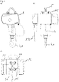
- the hoist selected as an exemplary embodiment consists essentially of a housing 1, which accommodates a gear 2, which is connected to a motor - not shown.
- the gear 2 drives a shaft 21, which is rotatably mounted in the housing 1 and on which a reel 3 is arranged, which receives a chain 4, at the end of which a load hook 41 is attached.
- the housing 1 is connected via a support bracket 5 to a cantilever arm 6--only indicated schematically--which accommodates the hoist.
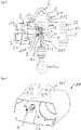
- the housing 1 consists essentially of a center piece 11, on one side of which a drive piece 12 and opposite this a control piece 13 is attached.
- the center piece 11 is designed essentially as a hollow cylinder and has a tubular receptacle 111 for the shaft guide 121 of the drive piece 12 on its inner wall.
- the receptacle 111 opens into a spindle space 112 which is designed to be open for the passage of the chain 4 on the underside of the center piece 11 opposite the support bracket 5 .
- the spindle space 12 is delimited by a partition 113 which has a passage 114 for the journal 22 of the shaft 21 .
- An inductive distance sensor 7 is arranged on the partition wall 113 at a radial distance from the passage 114 and is connected via a line 81 to a computer module 8 arranged in the control piece 13 .
- flange parts 115 are formed on the center piece 11 of the housing 1, to which flange parts 115 the support bracket 5 is fastened by means of bolts 51.
- the drive piece 12 of the housing 1 is essentially bell-shaped in such a way that its outer wall, which has an enlarged diameter, merges into the outer wall of the center piece 11 of the housing 1, on which the drive piece 12 rests.
- a bottle-like shaft guide 121 is formed on the inside of the drive piece 12, and a ball bearing 9 for supporting the shaft 21 of the transmission 2 is arranged on the reduced-diameter, bottle-neck-like end of the shaft guide.
- a bearing seat 122 is formed in the drive piece 12 , which in turn accommodates a ball bearing 9 for supporting the shaft 21 .
- the outside diameter of the end of the shaft guide 21 with the reduced diameter essentially corresponds to the inside diameter of the receptacle 111 of the center piece 11 of the housing 1, into which the wave guide 121 is inserted.
- the control piece 13 is formed on the center piece 11 of the housing 1 and accommodates the motor control of the hoist. On its underside facing away from the support bracket 5 , the control piece 13 has a passage 131 for a control line 132 to pass through.
- a computer module 8 which is connected to a memory module 82 and a display 83 is also arranged in the control piece.
- the shaft 21 of the gear 2 is held by the two ball bearings 9 of the drive piece 12 of the housing 1 and protrudes at the end into the spindle space 112 of the middle piece 11, in which a reel 3 is arranged, which is fastened to the shaft 21.
- a pin 22 is formed axially on the shaft 21 and projects through the passage 114 of the partition wall 113 without making contact and is arranged at a defined distance from the inductive distance sensor 7 .
- the computer module 8 is connected to a memory unit 82 in which determined load values for different reference distances between the distance sensor 7 and the pin 22 are stored.
- the computer module 8 is set up in such a way that, based on the measurement distances reported by the distance sensor 7, the respective applied load is determined.
- the computer module 8 is connected to a display 83 on which the load values determined by the computer module 8 are displayed.
- a defined section of the housing 1 can also function as the measurement object.
- the twisting of the housing 1 changes the distance of this defined section from the distance sensor 7. This change in distance is measured by the inductive distance sensor 7 and in turn transmitted to the computer module 8, which determines the applied force on the basis of this measured value.
Landscapes
- Physics & Mathematics (AREA)
- General Physics & Mathematics (AREA)
- Engineering & Computer Science (AREA)
- Mechanical Engineering (AREA)
- Control And Safety Of Cranes (AREA)
- Length Measuring Devices With Unspecified Measuring Means (AREA)
Claims (7)
- Engin de levage, en particulier palan à câble ou à chaîne, comprenant un mécanisme servant à lever et abaisser une charge, comprenant un carter (1) recevant un moteur lui-même relié à un réducteur (2), lequel réducteur entraîne un arbre (21) en appui rotatif dans le carter (1) et sur lequel arbre est disposé un dévidoir (3) recevant un câble ou une chaîne (4) guidée à travers une ouverture du carter (1) et qui présente en son extrémité un crochet porte-charge (41), sachant que dans le carter (1) est présent un dispositif de mesure servant à la saisie continue de la charge appliquée au crochet porte-charge (41), sachant que le dispositif de mesure comprend un capteur de distance (7) qui est fixé contre le carter (1) à une distance définie - lorsque le câble ou la chaîne (4) se trouve hors charge - d'un objet de mesure relié à l'arbre (21) ou au carter (1), caractérisé en ce que le capteur de distance (7) est relié à un module calculateur (8) configuré pour déterminer la charge appliquée sur la base de la distance transmise par le capteur de distance (7).
- Engin de levage selon la revendication 1, caractérisé en ce que l'objet de mesure est une fusée (22) disposée axialement contre l'arbre.
- Engin de levage selon la revendication 1, caractérisé en ce que l'objet de mesure est une partie intégrante définie du carter (1).
- Engin de levage selon l'une des revendications précédentes, caractérisé en ce que le capteur de distance (7) est configuré sans contact physique, notamment comme capteur inductif, capacitif ou optique de distance.
- Engin de levage selon l'une des revendications précédentes, caractérisé en ce que le module calculateur (8) contient un algorithme servant à calculer une charge sur la base d'un écart de mesure signalé par le capteur de distance (7).
- Engin de levage selon l'une des revendications précédentes, caractérisé en ce que le module calculateur (8) est relié à une unité mémoire (82) contenant des valeurs de charge déterminées empiriquement pour différentes distances de référence entre la fusée (22) et le capteur de distance (7), sachant que le module calculateur (8) est configuré pour déterminer - sur la base de la distance de mesure déterminée par le capteur de distance - la charge en présence par interpolation des valeurs de distance et de charge en mémoire.
- Engin de levage selon l'une des revendications précédentes, caractérisé en ce que le module calculateur (8) est relié avec un moniteur (83) pour afficher les valeurs de charge déterminées.
Priority Applications (2)
| Application Number | Priority Date | Filing Date | Title |
|---|---|---|---|
| EP20171320.3A EP3901083B1 (fr) | 2020-04-24 | 2020-04-24 | Engin de levage, en particulier palan à câble ou à chaîne |
| PL20171320.3T PL3901083T3 (pl) | 2020-04-24 | 2020-04-24 | Wciągnik, w szczególności wciągnik linowy lub łańcuchowy |
Applications Claiming Priority (1)
| Application Number | Priority Date | Filing Date | Title |
|---|---|---|---|
| EP20171320.3A EP3901083B1 (fr) | 2020-04-24 | 2020-04-24 | Engin de levage, en particulier palan à câble ou à chaîne |
Publications (2)
| Publication Number | Publication Date |
|---|---|
| EP3901083A1 EP3901083A1 (fr) | 2021-10-27 |
| EP3901083B1 true EP3901083B1 (fr) | 2022-08-10 |
Family
ID=70464865
Family Applications (1)
| Application Number | Title | Priority Date | Filing Date |
|---|---|---|---|
| EP20171320.3A Active EP3901083B1 (fr) | 2020-04-24 | 2020-04-24 | Engin de levage, en particulier palan à câble ou à chaîne |
Country Status (2)
| Country | Link |
|---|---|
| EP (1) | EP3901083B1 (fr) |
| PL (1) | PL3901083T3 (fr) |
Family Cites Families (4)
| Publication number | Priority date | Publication date | Assignee | Title |
|---|---|---|---|---|
| US7559533B2 (en) * | 2006-01-17 | 2009-07-14 | Gorbel, Inc. | Lift actuator |
| DE102011115910B4 (de) | 2011-10-14 | 2013-06-06 | ABUS Kransysteme GmbH & Co. KG | Hebezeug, insbesondere Seil- oder Kettenzug |
| US10093523B2 (en) * | 2014-10-06 | 2018-10-09 | Warn Industries, Inc. | Programmable controls for a winch |
| JP7029720B2 (ja) * | 2017-10-11 | 2022-03-04 | ユニパルス株式会社 | 電動昇降装置及びその制御方法 |
-
2020
- 2020-04-24 EP EP20171320.3A patent/EP3901083B1/fr active Active
- 2020-04-24 PL PL20171320.3T patent/PL3901083T3/pl unknown
Also Published As
| Publication number | Publication date |
|---|---|
| EP3901083A1 (fr) | 2021-10-27 |
| PL3901083T3 (pl) | 2022-11-28 |
Similar Documents
| Publication | Publication Date | Title |
|---|---|---|
| EP3038968B1 (fr) | Dispositif de détermination du moment de dépose d'un câble de fibres ultra-résistant lorsqu'il est utilisé dans des engins de levage | |
| EP3359481B1 (fr) | Dispositif de support pour supporter un dispositif mobile | |
| DE102009006329B4 (de) | Hubvorrichtung, insbesondere für ein Flurförderzeug | |
| DE19512103C2 (de) | Seilwinde mit Betriebsdatenerfassung | |
| EP2070864B1 (fr) | Procédé destiné au fonctionnement d'un chariot de manutention | |
| EP3038966B1 (fr) | Émerillon | |
| EP0563836A2 (fr) | Méthode pour mesurer la capacité d'entraînement d'un installation de transport | |
| EP3901083B1 (fr) | Engin de levage, en particulier palan à câble ou à chaîne | |
| DE102020111283A1 (de) | Hebezeug, insbesondere Seil- oder Kettenzug | |
| EP2994726B1 (fr) | Porte-charge élastiquement déformable comprenant un dispositif de mesure de la charge | |
| DE3819447A1 (de) | Vorrichtung zur regelung der zugkraft einer winde | |
| AT503455B1 (de) | Statische treibfähigkeitsprüfung | |
| DE102011115910A1 (de) | Hebezeug, insbesondere Seil- oder Kettenzug | |
| WO2020239567A1 (fr) | Mécanisme de levage hydrostatique, machine de travail mobile pourvue de celui-ci, et procédé permettant de déterminer une charge sur le mécanisme de levage | |
| DE10224418B4 (de) | Seiltrommel mit Sensorik zur Begrenzung des Abwickelns des Hubseils | |
| EP3760573B1 (fr) | Chariot élévateur à fourche rétractable | |
| DE102019126687A1 (de) | Kran | |
| DE3832000A1 (de) | Vorrichtung zum messen der zugkraft von winden, insbesondere fuer konstantzugewinden auf schiffen | |
| EP2520534B1 (fr) | Dispositif de détection de charge sur des engins de levage et engins à chaînes électriques | |
| CH656715A5 (en) | Device for testing the weight of vehicle wheels and vehicle axles for brake test stands | |
| WO2023126138A1 (fr) | Cylindre électromécanique | |
| DE19916165C2 (de) | Federkraftbremse für einen Antriebsmotor einer Lasthebeeinrichtung | |
| DE19720325C1 (de) | Kraftmeßeinrichtung in einem Stellantrieb zur Steuerung von Armaturen | |
| DE102007060433A1 (de) | Verfahren zum Betrieb eines Flurförderzeugs | |
| DE29812736U1 (de) | Hydraulischer Aufzug |
Legal Events
| Date | Code | Title | Description |
|---|---|---|---|
| PUAI | Public reference made under article 153(3) epc to a published international application that has entered the european phase |
Free format text: ORIGINAL CODE: 0009012 |
|
| STAA | Information on the status of an ep patent application or granted ep patent |
Free format text: STATUS: REQUEST FOR EXAMINATION WAS MADE |
|
| 17P | Request for examination filed |
Effective date: 20210414 |
|
| AK | Designated contracting states |
Kind code of ref document: A1 Designated state(s): AL AT BE BG CH CY CZ DE DK EE ES FI FR GB GR HR HU IE IS IT LI LT LU LV MC MK MT NL NO PL PT RO RS SE SI SK SM TR |
|
| B565 | Issuance of search results under rule 164(2) epc |
Effective date: 20201016 |
|
| GRAP | Despatch of communication of intention to grant a patent |
Free format text: ORIGINAL CODE: EPIDOSNIGR1 |
|
| STAA | Information on the status of an ep patent application or granted ep patent |
Free format text: STATUS: GRANT OF PATENT IS INTENDED |
|
| INTG | Intention to grant announced |
Effective date: 20211124 |
|
| GRAS | Grant fee paid |
Free format text: ORIGINAL CODE: EPIDOSNIGR3 |
|
| GRAA | (expected) grant |
Free format text: ORIGINAL CODE: 0009210 |
|
| STAA | Information on the status of an ep patent application or granted ep patent |
Free format text: STATUS: THE PATENT HAS BEEN GRANTED |
|
| AK | Designated contracting states |
Kind code of ref document: B1 Designated state(s): AL AT BE BG CH CY CZ DE DK EE ES FI FR GB GR HR HU IE IS IT LI LT LU LV MC MK MT NL NO PL PT RO RS SE SI SK SM TR |
|
| REG | Reference to a national code |
Ref country code: AT Ref legal event code: REF Ref document number: 1510424 Country of ref document: AT Kind code of ref document: T Effective date: 20220815 Ref country code: CH Ref legal event code: EP |
|
| REG | Reference to a national code |
Ref country code: IE Ref legal event code: FG4D Free format text: LANGUAGE OF EP DOCUMENT: GERMAN |
|
| REG | Reference to a national code |
Ref country code: DE Ref legal event code: R096 Ref document number: 502020001492 Country of ref document: DE |
|
| REG | Reference to a national code |
Ref country code: NL Ref legal event code: FP |
|
| REG | Reference to a national code |
Ref country code: LT Ref legal event code: MG9D |
|
| PG25 | Lapsed in a contracting state [announced via postgrant information from national office to epo] |
Ref country code: SE Free format text: LAPSE BECAUSE OF FAILURE TO SUBMIT A TRANSLATION OF THE DESCRIPTION OR TO PAY THE FEE WITHIN THE PRESCRIBED TIME-LIMIT Effective date: 20220810 Ref country code: RS Free format text: LAPSE BECAUSE OF FAILURE TO SUBMIT A TRANSLATION OF THE DESCRIPTION OR TO PAY THE FEE WITHIN THE PRESCRIBED TIME-LIMIT Effective date: 20220810 Ref country code: PT Free format text: LAPSE BECAUSE OF FAILURE TO SUBMIT A TRANSLATION OF THE DESCRIPTION OR TO PAY THE FEE WITHIN THE PRESCRIBED TIME-LIMIT Effective date: 20221212 Ref country code: NO Free format text: LAPSE BECAUSE OF FAILURE TO SUBMIT A TRANSLATION OF THE DESCRIPTION OR TO PAY THE FEE WITHIN THE PRESCRIBED TIME-LIMIT Effective date: 20221110 Ref country code: LV Free format text: LAPSE BECAUSE OF FAILURE TO SUBMIT A TRANSLATION OF THE DESCRIPTION OR TO PAY THE FEE WITHIN THE PRESCRIBED TIME-LIMIT Effective date: 20220810 Ref country code: LT Free format text: LAPSE BECAUSE OF FAILURE TO SUBMIT A TRANSLATION OF THE DESCRIPTION OR TO PAY THE FEE WITHIN THE PRESCRIBED TIME-LIMIT Effective date: 20220810 Ref country code: FI Free format text: LAPSE BECAUSE OF FAILURE TO SUBMIT A TRANSLATION OF THE DESCRIPTION OR TO PAY THE FEE WITHIN THE PRESCRIBED TIME-LIMIT Effective date: 20220810 |
|
| PG25 | Lapsed in a contracting state [announced via postgrant information from national office to epo] |
Ref country code: IS Free format text: LAPSE BECAUSE OF FAILURE TO SUBMIT A TRANSLATION OF THE DESCRIPTION OR TO PAY THE FEE WITHIN THE PRESCRIBED TIME-LIMIT Effective date: 20221210 Ref country code: HR Free format text: LAPSE BECAUSE OF FAILURE TO SUBMIT A TRANSLATION OF THE DESCRIPTION OR TO PAY THE FEE WITHIN THE PRESCRIBED TIME-LIMIT Effective date: 20220810 Ref country code: GR Free format text: LAPSE BECAUSE OF FAILURE TO SUBMIT A TRANSLATION OF THE DESCRIPTION OR TO PAY THE FEE WITHIN THE PRESCRIBED TIME-LIMIT Effective date: 20221111 |
|
| PG25 | Lapsed in a contracting state [announced via postgrant information from national office to epo] |
Ref country code: SM Free format text: LAPSE BECAUSE OF FAILURE TO SUBMIT A TRANSLATION OF THE DESCRIPTION OR TO PAY THE FEE WITHIN THE PRESCRIBED TIME-LIMIT Effective date: 20220810 Ref country code: RO Free format text: LAPSE BECAUSE OF FAILURE TO SUBMIT A TRANSLATION OF THE DESCRIPTION OR TO PAY THE FEE WITHIN THE PRESCRIBED TIME-LIMIT Effective date: 20220810 Ref country code: ES Free format text: LAPSE BECAUSE OF FAILURE TO SUBMIT A TRANSLATION OF THE DESCRIPTION OR TO PAY THE FEE WITHIN THE PRESCRIBED TIME-LIMIT Effective date: 20220810 Ref country code: DK Free format text: LAPSE BECAUSE OF FAILURE TO SUBMIT A TRANSLATION OF THE DESCRIPTION OR TO PAY THE FEE WITHIN THE PRESCRIBED TIME-LIMIT Effective date: 20220810 Ref country code: CZ Free format text: LAPSE BECAUSE OF FAILURE TO SUBMIT A TRANSLATION OF THE DESCRIPTION OR TO PAY THE FEE WITHIN THE PRESCRIBED TIME-LIMIT Effective date: 20220810 |
|
| REG | Reference to a national code |
Ref country code: DE Ref legal event code: R097 Ref document number: 502020001492 Country of ref document: DE |
|
| PG25 | Lapsed in a contracting state [announced via postgrant information from national office to epo] |
Ref country code: SK Free format text: LAPSE BECAUSE OF FAILURE TO SUBMIT A TRANSLATION OF THE DESCRIPTION OR TO PAY THE FEE WITHIN THE PRESCRIBED TIME-LIMIT Effective date: 20220810 Ref country code: EE Free format text: LAPSE BECAUSE OF FAILURE TO SUBMIT A TRANSLATION OF THE DESCRIPTION OR TO PAY THE FEE WITHIN THE PRESCRIBED TIME-LIMIT Effective date: 20220810 |
|
| P01 | Opt-out of the competence of the unified patent court (upc) registered |
Effective date: 20230413 |
|
| PLBE | No opposition filed within time limit |
Free format text: ORIGINAL CODE: 0009261 |
|
| STAA | Information on the status of an ep patent application or granted ep patent |
Free format text: STATUS: NO OPPOSITION FILED WITHIN TIME LIMIT |
|
| PG25 | Lapsed in a contracting state [announced via postgrant information from national office to epo] |
Ref country code: AL Free format text: LAPSE BECAUSE OF FAILURE TO SUBMIT A TRANSLATION OF THE DESCRIPTION OR TO PAY THE FEE WITHIN THE PRESCRIBED TIME-LIMIT Effective date: 20220810 |
|
| 26N | No opposition filed |
Effective date: 20230511 |
|
| REG | Reference to a national code |
Ref country code: CH Ref legal event code: PL |
|
| PG25 | Lapsed in a contracting state [announced via postgrant information from national office to epo] |
Ref country code: LU Free format text: LAPSE BECAUSE OF NON-PAYMENT OF DUE FEES Effective date: 20230424 |
|
| PG25 | Lapsed in a contracting state [announced via postgrant information from national office to epo] |
Ref country code: MC Free format text: LAPSE BECAUSE OF FAILURE TO SUBMIT A TRANSLATION OF THE DESCRIPTION OR TO PAY THE FEE WITHIN THE PRESCRIBED TIME-LIMIT Effective date: 20220810 |
|
| PG25 | Lapsed in a contracting state [announced via postgrant information from national office to epo] |
Ref country code: MC Free format text: LAPSE BECAUSE OF FAILURE TO SUBMIT A TRANSLATION OF THE DESCRIPTION OR TO PAY THE FEE WITHIN THE PRESCRIBED TIME-LIMIT Effective date: 20220810 Ref country code: LI Free format text: LAPSE BECAUSE OF NON-PAYMENT OF DUE FEES Effective date: 20230430 Ref country code: CH Free format text: LAPSE BECAUSE OF NON-PAYMENT OF DUE FEES Effective date: 20230430 |
|
| REG | Reference to a national code |
Ref country code: IE Ref legal event code: MM4A |
|
| PG25 | Lapsed in a contracting state [announced via postgrant information from national office to epo] |
Ref country code: IE Free format text: LAPSE BECAUSE OF NON-PAYMENT OF DUE FEES Effective date: 20230424 |
|
| PG25 | Lapsed in a contracting state [announced via postgrant information from national office to epo] |
Ref country code: IE Free format text: LAPSE BECAUSE OF NON-PAYMENT OF DUE FEES Effective date: 20230424 |
|
| PG25 | Lapsed in a contracting state [announced via postgrant information from national office to epo] |
Ref country code: IT Free format text: LAPSE BECAUSE OF FAILURE TO SUBMIT A TRANSLATION OF THE DESCRIPTION OR TO PAY THE FEE WITHIN THE PRESCRIBED TIME-LIMIT Effective date: 20220810 |
|
| PGFP | Annual fee paid to national office [announced via postgrant information from national office to epo] |
Ref country code: NL Payment date: 20240429 Year of fee payment: 5 |
|
| PGFP | Annual fee paid to national office [announced via postgrant information from national office to epo] |
Ref country code: GB Payment date: 20240522 Year of fee payment: 5 |
|
| PGFP | Annual fee paid to national office [announced via postgrant information from national office to epo] |
Ref country code: DE Payment date: 20240325 Year of fee payment: 5 |
|
| PGFP | Annual fee paid to national office [announced via postgrant information from national office to epo] |
Ref country code: FR Payment date: 20240423 Year of fee payment: 5 |
|
| PGFP | Annual fee paid to national office [announced via postgrant information from national office to epo] |
Ref country code: PL Payment date: 20240509 Year of fee payment: 5 |
|
| PGFP | Annual fee paid to national office [announced via postgrant information from national office to epo] |
Ref country code: BE Payment date: 20240419 Year of fee payment: 5 |