EP3359481B1 - Dispositif de support pour supporter un dispositif mobile - Google Patents
Dispositif de support pour supporter un dispositif mobile Download PDFInfo
- Publication number
- EP3359481B1 EP3359481B1 EP16790277.4A EP16790277A EP3359481B1 EP 3359481 B1 EP3359481 B1 EP 3359481B1 EP 16790277 A EP16790277 A EP 16790277A EP 3359481 B1 EP3359481 B1 EP 3359481B1
- Authority
- EP
- European Patent Office
- Prior art keywords
- bolt
- support
- supporting
- supporting device
- magnetic field
- Prior art date
- Legal status (The legal status is an assumption and is not a legal conclusion. Google has not performed a legal analysis and makes no representation as to the accuracy of the status listed.)
- Active
Links
- 230000005291 magnetic effect Effects 0.000 claims description 46
- 230000001419 dependent effect Effects 0.000 claims description 9
- 229920003023 plastic Polymers 0.000 claims description 6
- 239000004033 plastic Substances 0.000 claims description 6
- 230000000694 effects Effects 0.000 claims description 5
- 230000002093 peripheral effect Effects 0.000 claims 1
- 238000005259 measurement Methods 0.000 description 15
- 238000010008 shearing Methods 0.000 description 10
- 230000035882 stress Effects 0.000 description 10
- 230000005540 biological transmission Effects 0.000 description 6
- 238000013461 design Methods 0.000 description 4
- 238000000034 method Methods 0.000 description 4
- 230000005294 ferromagnetic effect Effects 0.000 description 3
- 238000012423 maintenance Methods 0.000 description 3
- 230000005415 magnetization Effects 0.000 description 2
- 238000012544 monitoring process Methods 0.000 description 2
- 230000032683 aging Effects 0.000 description 1
- 238000005452 bending Methods 0.000 description 1
- 238000009530 blood pressure measurement Methods 0.000 description 1
- 238000001514 detection method Methods 0.000 description 1
- 238000011161 development Methods 0.000 description 1
- 230000018109 developmental process Effects 0.000 description 1
- 230000007613 environmental effect Effects 0.000 description 1
- 230000005484 gravity Effects 0.000 description 1
- 239000000463 material Substances 0.000 description 1
- 230000002441 reversible effect Effects 0.000 description 1
- 239000003381 stabilizer Substances 0.000 description 1
Images


Classifications
-
- B—PERFORMING OPERATIONS; TRANSPORTING
- B66—HOISTING; LIFTING; HAULING
- B66C—CRANES; LOAD-ENGAGING ELEMENTS OR DEVICES FOR CRANES, CAPSTANS, WINCHES, OR TACKLES
- B66C23/00—Cranes comprising essentially a beam, boom, or triangular structure acting as a cantilever and mounted for translatory of swinging movements in vertical or horizontal planes or a combination of such movements, e.g. jib-cranes, derricks, tower cranes
- B66C23/62—Constructional features or details
- B66C23/72—Counterweights or supports for balancing lifting couples
- B66C23/78—Supports, e.g. outriggers, for mobile cranes
- B66C23/80—Supports, e.g. outriggers, for mobile cranes hydraulically actuated
-
- B—PERFORMING OPERATIONS; TRANSPORTING
- B66—HOISTING; LIFTING; HAULING
- B66C—CRANES; LOAD-ENGAGING ELEMENTS OR DEVICES FOR CRANES, CAPSTANS, WINCHES, OR TACKLES
- B66C23/00—Cranes comprising essentially a beam, boom, or triangular structure acting as a cantilever and mounted for translatory of swinging movements in vertical or horizontal planes or a combination of such movements, e.g. jib-cranes, derricks, tower cranes
- B66C23/88—Safety gear
- B66C23/90—Devices for indicating or limiting lifting moment
- B66C23/905—Devices for indicating or limiting lifting moment electrical
-
- G—PHYSICS
- G01—MEASURING; TESTING
- G01L—MEASURING FORCE, STRESS, TORQUE, WORK, MECHANICAL POWER, MECHANICAL EFFICIENCY, OR FLUID PRESSURE
- G01L1/00—Measuring force or stress, in general
- G01L1/20—Measuring force or stress, in general by measuring variations in ohmic resistance of solid materials or of electrically-conductive fluids; by making use of electrokinetic cells, i.e. liquid-containing cells wherein an electrical potential is produced or varied upon the application of stress
- G01L1/22—Measuring force or stress, in general by measuring variations in ohmic resistance of solid materials or of electrically-conductive fluids; by making use of electrokinetic cells, i.e. liquid-containing cells wherein an electrical potential is produced or varied upon the application of stress using resistance strain gauges
- G01L1/2206—Special supports with preselected places to mount the resistance strain gauges; Mounting of supports
- G01L1/2218—Special supports with preselected places to mount the resistance strain gauges; Mounting of supports the supports being of the column type, e.g. cylindric, adapted for measuring a force along a single direction
- G01L1/2225—Special supports with preselected places to mount the resistance strain gauges; Mounting of supports the supports being of the column type, e.g. cylindric, adapted for measuring a force along a single direction the direction being perpendicular to the central axis
-
- G—PHYSICS
- G01—MEASURING; TESTING
- G01L—MEASURING FORCE, STRESS, TORQUE, WORK, MECHANICAL POWER, MECHANICAL EFFICIENCY, OR FLUID PRESSURE
- G01L5/00—Apparatus for, or methods of, measuring force, work, mechanical power, or torque, specially adapted for specific purposes
- G01L5/0004—Force transducers adapted for mounting in a bore of the force receiving structure
Definitions
- the invention relates to a support device for supporting a mobile device.
- the masts which are now attached to large manipulators, such as mobile concrete pumps, reach considerable heights and, when extended or folded out, generate a high tilting moment that depends on the pivoting position and the length of the mast.
- large manipulators are supported on the ground during use.
- They have specially designed support devices.
- the support is usually provided by laterally extendable supports on which telescoping or lowerable elements (support feet) are provided, which establish contact with the ground.
- the supports form the corners of a square, the side lines of which circumscribe an area within which the overall center of gravity of the large manipulator must lie, so that stability is guaranteed.
- Monitoring the vertical load plays an important role in being able to determine the load on the supports based on this and, if necessary, to be able to restrict the movement of the mast and to avoid overloading the supports or tipping over of the large manipulator. It can also be important to monitor the tongue load to determine that the stabilizer feet are properly lowered and in contact with the ground.
- the DE 20 2014 000334 U1 relates to a supporting force measuring device for measuring a supporting force on a supporting element of a mobile working machine at least one measuring element, which is connected to a deformation body that is deformable under the action of the supporting force to form a sensor and emits a signal that is proportional to the supporting force.
- the DE 20 2014 000334 U1 discloses a landing gear according to the preamble of independent claim 1.
- the U.S. 2007/090612 A1 relates to a mobile working device with a vehicle chassis, two front and two rear outriggers, each with outriggers, each comprising a measuring element for determining the vertical load on each outrigger leg, with a connecting pin serving as a measuring element for determining the vertical load by a device occurring on the connecting pin elastic deflection to determine the vertical load specific to the support leg, with the connecting bolt accommodating two strain gauges for this purpose.
- the U.S. 4,752,012 A relates to a large mobile tower crane.
- a crane control system uses electronic sensing devices mounted at predetermined locations on the crane boom and tower to provide electrical signals related to crane load conditions.
- the sensing devices in the boom include strain gauges embodied in bolts that mechanically connect certain sections of the boom.
- a mobile working device with outriggers and telescopic support legs is known, the support legs being articulated on a support leg box via pivot bolts.
- the linkage bolts are designed as a measuring element for determining the support load, for which purpose the linkage bolts have strain gauges. Equipping the bolts with strain gauges has several disadvantages. On the one hand, such a configuration is very complex and the bolt is weakened at the point at which the strain gauge is inserted. Furthermore, strain gauges, as contact measuring devices, show signs of aging, so that complex and cost-intensive maintenance work is necessary for a permanently reliable function.
- the forces acting on the manipulator itself can be measured, for example, by measuring the hydraulic pressure on the hydraulic cylinders or with strain gauges attached to the mast arms. This allows, for example, an overload of the manipulator to be detected at an early stage in order to avoid overloading. These measurements can also be used to determine the force exerted by the manipulator on the chassis and thus on the supports, in order to prevent the large manipulator from tipping over, for example.
- a method for measuring the load of such a large manipulator by means of a hydraulic pressure measurement is for example in U.S. 5,359,516 specified, and a method for monitoring the stability of a large manipulator according to this measurement principle is in the EP 1 356 910 A1 specified.
- the determination of the hydraulic pressure of a hydraulic cylinder is z. B. because of the breakaway force acting in the hydraulic cylinder and undefined pressure conditions when the piston is in its end position, it may not be reliable enough to be able to clearly determine the forces for every operating situation.
- the object of the invention is to provide a supporting device in which an effective and permanently accurate detection of the supporting force can be ensured in a simple manner.
- the object of the invention is to provide a support device that can be integrated into existing structures of large manipulators, in particular truck-mounted concrete pumps, without great effort.
- the support force is that force (typically directed upwards) that acts on the support device when the mobile device is supported on the ground.
- the supporting force is introduced into the support in a vertical direction, e.g. via a support leg that can be lowered.
- the support device has the advantage over the prior art that the vertical load in the supports can be determined easily and reliably, so that based on this the ground contact of the supports or the support feet is automatically determined and/or the movement of the mast arm is dependent on the detected supporting force can be specifically controlled. According to the invention, this is achieved by the sensor device, which responds to the deformation of the bolt.
- An advantageous embodiment of the supporting device is characterized by at least one magnetized bolt that transmits at least part of the supporting force, with the sensor device having a magnetic field sensor that detects the magnetic field generated by the magnetized bolt.
- the magnetized bolt has a magnetic coding that generates a magnetic field that characterizes the supporting force at the location of the magnetic field sensor due to the inverse magnetostrictive effect.
- Magnetostriction is the deformation of magnetic, in particular ferromagnetic, materials as a result of an applied magnetic field.
- the body experiences an elastic change in length at a constant volume.
- Inverse magnetostriction takes advantage of the fact that the magnetization of a ferromagnetic body is altered by mechanical Stresses or changes due to the action of a force.
- the action of stresses and/or forces on a body causes its deformation, which changes its magnetic field.
- This change in the magnetic field or the field strength of the ferromagnetic body can be detected by a suitable sensor device (magnetic field sensor).
- the acting force can be deduced from the measuring signal of the magnetic field sensor.
- the bolt can be suitably provided with a spatial magnetization pattern, ie magnetically encoded, whereby a voltage is induced, for example, in a coil used as a magnetic field sensor when force is applied, which voltage is essentially linear to the applied force. Consequently, the amount of the support force can be detected by measuring the voltage.
- the principle of force measurement using a magnetized bolt is known from the prior art (see e.g WO 02/063262 A1 ).
- a further advantageous embodiment of the invention provides that the sensor device determines the stress on the magnetized bolt using the magnetic field as a measure of the transmitted supporting force. In this way, it is very easy to draw conclusions about the magnitude of the load that is exerted on the magnetized bolt by the supporting force.
- the embodiment in which the sensor device has at least one strain gauge on or in the bolt, which generates a signal characterizing the supporting force, is particularly advantageous.
- the arrangement of a strain gauge on the bolt provides a simple but reliable way of obtaining a signal that characterizes the supporting force. With the arrangement of the strain gauge in the bolt, the reliability of the sensor device can be further increased since the arrangement in the bolt makes the strain gauge independent of external environmental influences.
- a further advantageous embodiment of the invention provides that the bolt has a cavity for accommodating the sensor device and/or strain gauges having. Forming a closable cavity in the bolt makes it easier to accommodate the sensor device or the strain gauge in the bolt and makes maintenance work easier.
- the bolt has at least one circumferential groove.
- Circumferential grooves in the pin in particular cause greater shear deformation, so that a signal characterizing the supporting force can be detected more easily and this signal also provides more precise information about the magnitude of the supporting force transmitted.
- the sensor device of the support device according to the invention can be designed for a shear force measurement, for a deflection measurement or for a torque measurement.
- the supporting force is either converted into a torque acting on the bolt or a shearing force acting on the bolt or a bending force acting on the bolt.
- the preferably magnetized bolt z. B. connects two components of the supporting device with each other is claimed according to the transmission of the supporting force either to shear, deflection or torsion.
- An advantageous embodiment provides that the bolt is subjected to shear stress when the supporting force is transmitted.
- An embodiment of the invention provides that the magnetized bolt is subjected to twisting during the transmission of the support force.
- An advantageous embodiment provides that the bolt is subjected to deflection during the transmission of the supporting force.
- the use of the sensor device based on the inverse magnetostrictive effect offers the advantage that it measures without contact and without wear, which means that expensive maintenance work is no longer necessary. Furthermore, the non-contact measurement allows certain tolerances between the components without having a negative effect on the measured values. Even the presence of dirt in the vicinity of the bolt and the sensor does not affect the measurement result.
- the support has a support foot that can be raised and lowered by means of a hydraulic cylinder.
- the supporting device or the support is designed to be vertically telescopic.
- the telescoping part can be mounted on a preferably magnetized bolt.
- the support preferably has a support foot that can be raised or lowered by means of a hydraulic cylinder.
- the hydraulic cylinder is advantageously mounted on the support via the preferably magnetized bolt.
- a further embodiment provides that the support leg is mounted on the hydraulic cylinder via the preferably magnetized bolt.
- An alternative embodiment provides that the support leg is mounted on the hydraulic cylinder via a further bolt. It is also conceivable that both the support leg is mounted on the hydraulic cylinder via a preferably magnetized bolt and the hydraulic cylinder is mounted on the support via a further preferably magnetized bolt. In all cases, the supporting force is transmitted via the bolt or bolts, which are preferably magnetized.
- the invention provides that the support foot is mounted on the support via a universal joint, the bolt being a joint bolt of the universal joint.
- the supporting force always acts centrally on the bolt, without lateral offset, which means that the supporting force can still be determined with high accuracy even if the ground on which the support foot is supported is not completely level and the support foot is inclined to the support touches the ground.
- the universal joint has an anti-twist device.
- This anti-twist device ensures in a simple way that the bolt does not twist relative to the support foot and is fixed axially in the bearing housing.
- the universal joint has a further joint bearing bolt which is aligned transversely to the bolt and whose joint axis lies in a plane with the joint axis of the bolt.
- the arrangement of the joint axes of the universal joint on one level reduces the Height of the universal joint significantly, so that it can be arranged more easily on the support and the support foot.
- a particularly advantageous embodiment provides that the bolt is mounted in a bearing housing of the joint bearing bolt.
- the arrangement of the bolt in a bearing housing of the joint bearing bolt offers the advantage that the supporting force is optimally transmitted from the joint bearing bolt to the bolt via the bearing housing. It is of particular advantage here if the bearing housing has flat side surfaces, as this means that the shearing deformation or the shearing force is optimally transferred to the bolt. The transmission of these forces through the side surfaces to the bolt takes place particularly advantageously in the area of the circumferential grooves on the bolt, so that the supporting force can be determined particularly precisely.
- a self-lubricating plastic bearing is arranged between the bolt and the joint bearing bolt.
- the arrangement of a self-lubricating plastic bearing in the universal joint makes it durable and relatively maintenance-free.
- a support device not according to the invention with a substantially horizontally oriented support arm is described.
- the support arm is arranged on a base frame or chassis of the mobile device and is preferably designed to be telescopic, extendable or pivotable.
- the support is advantageously arranged at the end on the support arm.
- the connection between support and outrigger can be made via a preferably magnetized bolt.
- An advantageous embodiment provides that the support is arranged at the end on a substantially horizontally oriented support arm connected to a base frame of the mobile device.
- the support arm can be extended or swiveled out in the horizontal direction.
- a further advantageous embodiment is that the support is mounted on the support arm via the bolt.
- a further advantageous embodiment provides that the support is additionally mounted on the support arm via a bearing bolt arranged at a distance from the preferably magnetized bolt.
- This configuration offers the advantage that the preferably magnetized bolt can be made smaller since the full supporting force does not act on it.
- the support and the support arm are preferably connected to one another via the bearing pin in such a way that when a support force is present, the preferably magnetized pin is loaded with a shearing force.
- the support and the support arm can be connected to one another via a bearing bolt in such a way that a support force acting on the support device leads to a torque stress on the preferably magnetized bolt.
- the bearing pin can be displaced relative to the support arm or relative to the support in a direction transverse to its longitudinal extension.
- either the support or the support arm can have a groove, an elongated hole or a slot, within which the bearing pin is slidably arranged.
- a further embodiment provides that the preferably magnetized bolt is non-rotatably connected to the support and to the support arm. When force is applied, this arrangement causes the preferably magnetized bolt to be twisted. The torque depends directly on the acting supporting force.
- the support arm can be connected to the base frame or a vehicle frame of the vehicle via a preferably magnetized bolt. This is particularly advantageous when the support arm is arranged pivotably on the vehicle frame.
- a further embodiment provides that the bolt is part of a guide that guides the extendable outrigger on the base frame of the vehicle. If the outriggers are arranged in an extendable manner on the vehicle frame, then the outriggers are ideally guided in or on a guide.
- the preferably magnetized bolt can be part of such a guide.
- the large manipulator comprises a support device, a mast arm, which has a turntable that can be rotated about a vertical axis, and a plurality of mast segments, with the mast segments being pivotably connected to articulated joints via joint pins with an adjacent mast segment or the turntable, with the mast segments being pivoted against the turntable by means of hydraulic cylinders or can be pivoted against each other, which act on the mast segments via pivot bolts, and a mast sensor system that generates a signal dependent on the mast load, with at least one of the pivot bolts or the pivot bolt being reversibly deformable and the mast sensor system having a sensor that detects the deformation of the pivot bolt or pivot bolt responds.
- the large manipulator has the advantage that the load on the joint bolts can be determined simply and reliably, so that the movement of the mast arm or the individual mast segments can be controlled in a targeted manner on this basis. An overload of the mast can be detected early.
- An advantageous embodiment of the large manipulator provides that the hinge pin or the linkage bolt is magnetized, with a magnetic field sensor detecting the magnetic field generated by the hinge pin or linkage bolt.
- the load on the joint bolts can be determined easily and reliably, so that based on this, the movement of the mast arm or the individual mast segments can be controlled in a targeted manner.
- An overload of the mast can be detected early.
- the non-contact measurement of the mast load is based on the principle of inverse magnetostriction and works as previously described in relation to the support device.
- a further advantageous embodiment of the large manipulator is that the hinge pin or the linkage bolt has at least one strain gauge on or in the hinge pin or linkage bolt, which generates a signal characterizing the supporting force.
- both pivot bolts can also be magnetized and equipped with sensors in order to compare the measurement results with one another and, if necessary, to initiate emergency measures if the measurement results do not match. This also applies to a combination of link bolts and hinge bolts.
- the large manipulator has a support device according to the invention.
- This large manipulator comprises a support device, a mast arm, which has a turntable that can be rotated about a vertical axis and a plurality of mast segments, with the mast segments being pivotably connected to articulated joints via joint pins with an adjacent mast segment or the turntable, and a sensor device that generates a load-dependent signal generated, wherein at least one bolt which is reversibly deformable is provided, wherein the sensor device has a sensor which responds to the deformation of the bolt.
- An advantageous embodiment of the large manipulator provides that the bolt is magnetized, with the sensor device having a magnetic field sensor that detects the magnetic field generated by the magnetized bolt.
- a further advantageous embodiment of the large manipulator is that the bolt has at least one strain gauge on or in the bolt, which generates a signal characterizing the supporting force.
- FIG 1 shows a schematic side view of a large manipulator 10 in a possible embodiment.
- the exemplary embodiment is a mobile concrete pump.
- the large manipulator 10 has a chassis or Base frame 12 on which an extendable or pivotable mast 14 with a plurality of mast segments 16, 18, 20 and a support system 22 are arranged.
- the mast segments 16, 18, 20 are pivotally connected to an adjacent mast segment 16, 18, 20 or a turntable 30 at articulated joints via pivot pins 24, 26, 28.
- the mast segments 16, 18, 20 are pivoted against each other or against the turntable 30 by means of hydraulic cylinders 56.
- FIG 1 only the hydraulic cylinder 56 between the turntable 30 and the first mast segment 20 is shown.
- the large manipulator 10 also has at least one mast sensor system A, B, which generates a signal dependent on the mast load.
- the mast sensor system A, B, Ba, Bb preferably includes a magnetic field sensor that detects the magnetic field generated by the preferably magnetized pivot pin 24, 26, 28 or the preferably magnetized pivot pin 57, 57a.
- the deformation of the hinge pins 24, 26, 28 or the pivot pins 57, 57a can also be detected in a different way.
- the mast sensor system A, B, Ba, Bb can have a sensor which responds to the deformation of the hinge pin 24, 26, 28 or the pivot pin 57, 57a.
- a strain gauge 58 ( 11 ) provided, which generates a signal characterizing the supporting force.
- both pivot bolts 57, 57a can also be magnetized and equipped with sensors B, Bb, for example, in order to compare the measurement results with one another and, if necessary, if the take emergency measures. This also applies to a combination of pivot bolts 57, 57a and pivot bolts 24, 26, 28.
- the load moment of the mast arm 14 acting on the turntable 30 can be determined by measuring the force on the mast joint, whether on the hinge pin 24 or on one of the pivot pins 57, 57a, which, taking into account the position of the supports, determines the stability of the large manipulator 10 can be monitored, and thus overturning of the large manipulator can be prevented.
- the support system 22 preferably comprises two front 32 and two rear supports 34, which advantageously each have a horizontally extending support arm 36, 38 and a support 40, 42 with a telescoping element.
- the rear and/or the front support 32, 34 can have a support device with a sensor device C, D, E, F, with the sensor device C, D, E, F preferably comprising a magnetic field sensor that generates the magnetic field generated by a magnetized bolt 44 magnetic field detected.
- the rear and/or the front support 32, 34 can have a support device with a sensor device C, D, E, F, the sensor device C, D, E, F preferably having a sensor which responds to the deformation of the bolt 44.
- This sensor is preferably designed as a strain gauge 58 ( 11 ) formed, which generates a signal characterizing the supporting force.
- FIG 2 shows a schematic view of a supporting device in a first embodiment.
- the support device shown is preferably the rear support 34 of the large manipulator 10.
- the support arm 38 is connected to the base frame 12 by a preferably magnetized bolt 44.
- the bolt 44 transmits the support force from the support arm 38 to the base frame 12.
- the support device also has a sensor device C, which generates a signal dependent on the support force.
- the sensor device C preferably has a magnetic field sensor (not shown), which detects the magnetic field generated by the bolt 44, which is preferably magnetized.
- the preferably magnetized bolt 44 is designed in such a way that it has a magnetic coding which reduces the supporting force at the location of the magnetic field sensor by the inverse magnetostrictive effect characterizing magnetic field generated.
- the deformation of the bolt 44 can also be detected in a different way.
- the sensor device C can have a sensor that responds to the deformation of the bolt 44 .
- a strain gauge 58 ( 11 ) provided, which generates a signal characterizing the supporting force. If the large manipulator 10 is supported by means of the support system 22, then the bolt 44 between the support arm 38 and the chassis 12 is subjected to shear stress. The associated deformation of the bolt 44 or change in the magnetic field is detected by the sensor device and can be used to determine the load on the support, for example in this way to automatically determine that the support 42 is in contact with the ground.
- FIGS. 3a and 3b show a schematic representation of a supporting device in a second embodiment. While Figure 3a shows a front view Figure 3b a side view of the support device.
- the support 40 shown has a support foot 48 which can be raised and lowered by means of a hydraulic cylinder 46 .
- the hydraulic cylinder 46 is mounted on the support 40 via a preferably magnetized bolt 44a. If the supporting force acts on the hydraulic cylinder 46, then the bolt 44a is subjected to shear stress and its magnetic field changes.
- the sensor device D or the magnetic field sensor of the sensor device D detects the magnetic field generated by the bolt 44a and uses it to determine the load on the support 40. Alternatively, the load on the bolt 44a can also be detected in a different way.
- the sensor device D can have a sensor that responds to the deformation of the bolt 44a.
- a strain gauge 58 ( 11 ) provided, which generates a signal characterizing the supporting force.
- a sensor device E is alternatively arranged here between the support foot 48 and the hydraulic cylinder 46 .
- the support foot 48 is mounted on the hydraulic cylinder 46 via a preferably magnetized bolt 44b.
- figure 4 shows a schematic side view of a supporting device in a third embodiment.
- the end of the support 40 is mounted on the support bracket 36 via a preferably magnetized bolt 44c.
- a support force acts.
- the sensor device F can have a sensor that responds to the deformation of the bolt 44c.
- a strain gauge 58 ( 11 ) provided, which generates a signal characterizing the supporting force.
- figure 5 shows a schematic side view of a supporting device in a fourth embodiment.
- the support 40 is at the end, as already in figure 4 , mounted on the support arm 36 via the preferably magnetized bolt 44c'.
- the support 40 is also mounted on the support arm 36 via a bearing pin 50 .
- This configuration offers the advantage that the preferably magnetized bolt 44c can be made smaller since it does not carry the full supporting force.
- the support 40 and the support arm 36 are connected to one another via the bearing pin 50 in such a way that when a supporting force is present, the preferably magnetized pin 44c is subjected to shearing stress.
- figure 6 shows a schematic side view of a supporting device in a fifth embodiment.
- the support 40 is arranged on the support arm 36 by means of two bolts, namely a bearing bolt 50 and a preferably magnetized bolt 44d.
- the support 40 and the support arm 36 are in figure 6 connected to one another via the bearing pin 50 in such a way that a supporting force acting on the supporting device leads to a torque stress on the pin 44d.
- This is achieved in that the bearing pin 50 can be displaced relative to the support arm 36 or relative to the support 40 in a direction transverse to its longitudinal extension.
- either the support 40 or the support arm 36 has an elongated hole 52, within which the bearing pin 50 is arranged so that it can be displaced to a limited extent.
- FIG 7 shows a schematic view of a supporting device in a sixth embodiment.
- the support device has an extendable support arm 38a which can be telescoped (in the direction perpendicular to the plane of representation).
- a guide 54 is arranged on the base frame 12 of the vehicle and guides the outrigger 38a.
- the preferably magnetized bolt 44e is part of the guide 54, so that the acting supporting force is at least partially transmitted to the base frame 12 via the bolt 44e.
- the bolt 44e is subjected to shear stress.
- the sensor device G detects the change in the magnetic field of the preferably magnetized bolt 44e, which results from the action of the shearing force and the corresponding deformation of the bolt 44e. Alternatively, the deformation of the bolt 44e can also be detected in a different way.
- the sensor device G can have a sensor that responds to the deformation of the bolt 44e.
- a strain gauge 58 ( 11 ) provided, which generates a signal characterizing the supporting force.
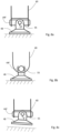
- FIGS Figures 8a, 8b and 8c show a schematic view of a supporting device according to the invention in a seventh embodiment, which is an improvement to the sensor device E according to FIGS Figures 3a and 3b represents.
- the preferably magnetized bolt 44f is arranged between the support 40 and the support foot 48 at the lower end of the hydraulic cylinder 46 .
- a universal joint arrangement 55 is provided between the support foot 48 and the support 40, the preferably magnetized bolt 44f forming an element of the universal joint arrangement.
- the preferably magnetized bolt 44f is arranged on the support 46, but can alternatively also be arranged on the support foot 48.
- the supporting force (represented by the arrow F) always acts centrally, without lateral offset, on the preferably magnetized bolt 44f, as a result of which the supporting force can still be determined with high accuracy even if the ground on which the large manipulator is supported , is not completely level and the support leg 48 is at an angle to the support, as in Figure 8c , touches down on the ground.
- a support 40 can preferably have several Magnetized bolts can be arranged at different positions with corresponding sensors in order to obtain redundant measurement results.
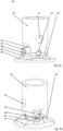
- the Figure 9a shows a perspective front view of a supporting device according to the invention in the seventh embodiment.
- the bolt 44f is located between the support 40 and the support leg 48 at the lower end of the hydraulic cylinder 46 ( figure 5 ) arranged.
- the support 40 has a linkage 67 for the hydraulic cylinder 46 ( figure 5 ) on.
- a gimbal assembly 55 is provided between the support foot 48 and the bracket 40, with the pin 44f forming a member of the gimbal assembly.
- This cardan joint designed as a universal joint 55 ensures that the support foot 48 is movably mounted on the support 40 .
- the bolt 44 is designed as a joint bolt of the universal joint 55 .
- the universal joint 55 has a further joint bearing bolt 62 which is aligned transversely to the bolt 44f and whose joint axis 63 ( Figure 10b ) in a plane with the hinge axis 64 ( Figure 10b ) of the bolt 44f.
- the bolt 44f is mounted on the support foot 48 via a support bearing 68 , the support bearing 68 being reinforced by support plates 69 in relation to the support foot 48 .
- the bolt 44f is arranged on the support foot 48, but can alternatively also be arranged on the support 46.
- the support force always acts centrally, without lateral offset, on the preferably magnetized bolt 44f, which means that the support force can still be determined with high accuracy even if the ground on which the large manipulator is supported is not completely level and the support leg 48 at an angle to the support, as in Figure 8c , touches down on the ground.
- the universal joint 55 has an anti-twist device 61 .
- the universal joint 55 has an anti-twist device 61 . This anti-twist device 61 prevents the bolt 44 from twisting relative to the support foot 48 .
- the bolt 44 is mounted in a block-shaped bearing housing 65 of the joint bearing bolt 62, which Figure 9b is easy to see.
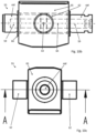
- the Figure 10a shows a perspective detailed view of the universal joint 55, which is formed by the bolt 44f and the joint bearing bolt 62.
- the joint bearing bolt 62 is firmly connected to the bearing housing 65 .
- the arrangement of the bolt 44f in the bearing housing 65 of the joint bearing bolt 62 ensures that the supporting force is optimally transmitted from the joint bearing bolt 62 via the bearing housing 65 to the bolt 44f.
- the flat side surfaces 70 of the bearing housing 65 lead to an optimal transmission of the shearing deformation or the shearing force to the bolt 44f.
- the transmission of these forces through the side surfaces 70 to the bolt 44f takes place particularly advantageously in the area of the circumferential grooves 60 on the bolt 44f, so that the supporting force can be determined particularly precisely.
- the Figure 10b shows a side view of the universal joint 55, the universal joint being shown from the point of view of the joint axis 63 of the joint bearing pin 62.
- the joint axis 64 of the bolt 44f lies transversely to the joint axis 63 of the joint bearing bolt 62.
- the joint axes 63, 64 lie in a horizontal plane.
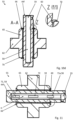
- a cavity 59 is formed in the bolt 44f.
- the sensor device and/or the strain gauge or strain gauges can be arranged in this cavity 59 .
- a self-lubricating plastic bearing 66 is arranged between the bolt 44f and the joint bearing bolt 62 .
- the Figure 10c shows a side view of the universal joint 55 as seen from the joint axis 64 of the bolt 44f.
- a section plane AA is drawn in this figure.
- FIG. 10d is a sectional view of the universal joint 55 according to FIG Figure 10c marked section plane AA.
- This sectional view clearly shows how the bolt 44f is accommodated in the bearing housing 65 of the joint bearing bolt 62 .
- the self-lubricating plastic bearing 66 is arranged between the bolt 44f and the bearing housing 65.
- FIG. The circumferential grooves 60 on the bolt 44f are arranged in such a way that the force transmitted from the side surfaces 70 of the bearing housing 65 to the bolt 44f is optimally introduced as a shearing force to the bolt 44f for measurement.
- FIG. 11 Out of figure 11 is a sectional view of the universal joint 55 according to FIG Figure 10c marked section plane AA.
- the sectional view clearly shows that several sensors 71, 71a of the sensor device H are arranged in the bolt 44f.
- the two sensors 71, 71a already offer a certain redundancy, but this can be increased by additional sensors.
- the sensors 71, 71a are located in a cavity 59 which is arranged as a bore in the bolt 44f.
- the sensors 71, 71a can be magnetic field sensors that detect the magnetic field generated by the bolt 44f, which is magnetized in this case.
- the bolt 44f is magnetically encoded and the sensors 71, 71a, which are arranged in the cavity 59 in the area of the grooves 60, detect the shearing deformation of the bolt 44f or the magnetic field change generated by the deformation of the bolt 44f.
- the sensors 71, 71a are designed as strain gauges 58 and generate a signal characterizing the supporting force based on the reversible deformation of the bolt 44f, which acts on the strain gauges 58 arranged in the bolt 44f...
- the sensor device H arranged in the bolt 44f is a circuit board formed and also includes an amplifier 72 and / or transducer for the measurement signals.
- a plug 73 is arranged on the right-hand side, with which the signals from the sensor device H can be transmitted to the control unit (not shown).
Landscapes
- Physics & Mathematics (AREA)
- General Physics & Mathematics (AREA)
- Engineering & Computer Science (AREA)
- Mechanical Engineering (AREA)
- Manipulator (AREA)
- Force Measurement Appropriate To Specific Purposes (AREA)
Claims (12)
- Dispositif de support pour supporter un dispositif mobile, notamment un véhicule, sur le sol, avec un support (40, 42) et un appareil capteur (C, D, E, F, G) qui produit un signal dépendant de la force de support, avec au moins un boulon (44, 44a, 44b, 44c, 44d, 44e, 44f) qui transmet au moins une partie de la force de support, moyennant quoi le boulon (44, 44a, 44b, 44c, 44d, 44e, 44f) est déformé de manière réversible, l'appareil capteur (C, D, E, F, G) réagissant à la déformation du boulon (44, 44a, 44b, 44c, 44d, 44e, 44f), le support (40, 42) présentant un pied de support (48) pouvant être soulevé et abaissé au moyen d'un vérin hydraulique (46),
caractérisé en ce que
le pied de support (48) est monté sur le support (40, 42) par l'intermédiaire d'une articulation en croix (55), le boulon (44f) étant un boulon d'articulation de l'articulation en croix (55). - Dispositif de support selon la revendication 1, caractérisé en ce que le boulon (44, 44a, 44b, 44c, 44d, 44e, 44f) est magnétisé, l'appareil capteur (C, D, E, F, G) présentant un capteur de champ magnétique qui détecte le champ magnétique produit par le boulon magnétisé (44).
- Dispositif de support selon la revendication 2, caractérisé en ce que le boulon magnétisé (44, 44a, 44b, 44c, 44d, 44e, 44f) présente un codage magnétique qui produit, à l'emplacement du capteur de champ magnétique, un champ magnétique caractérisant la force de support par l'effet magnétostrictif inverse.
- Dispositif de support selon la revendication 2 ou 3, caractérisé en ce que l'appareil capteur (C, D, E, F, G) détermine la sollicitation du boulon magnétisé (44, 44a, 44b, 44c, 44d, 44e, 44f) à l'aide du champ magnétique en tant que mesure de la force de support transmise.
- Dispositif de support selon la revendication 1, caractérisé en ce que l'appareil capteur (C, D, E, F, G) présente au moins une jauge de contrainte (58) sur ou dans le boulon (44, 44a, 44b, 44c, 44d, 44e, 44f), qui produit un signal caractérisant la force de support.
- Dispositif de support selon la revendication 5, caractérisé en ce que le boulon (44, 44a, 44b, 44c, 44d, 44e, 44f) présente une cavité (59) pour recevoir l'appareil capteur (C, D, E, F, G) et/ou la jauge de contrainte (58).
- Dispositif de support selon l'une quelconque des revendications 1 à 6, caractérisé en ce que le boulon (44, 44a, 44b, 44c, 44d, 44e, 44f) présente au moins une rainure périphérique (60).
- Dispositif de support selon l'une quelconque des revendications 1 à 7, caractérisé en ce que le boulon (44, 44a, 44b, 44c, 44d, 44e, 44f) est soumis à un cisaillement lors de la transmission de la force de support.
- Dispositif de support selon l'une quelconque des revendications 1 à 8, caractérisé en ce que l'articulation en croix (55) présente un moyen de blocage en rotation (61).
- Dispositif de support selon l'une quelconque des revendications 1 à 9, caractérisé en ce que l'articulation en croix (55) présente un autre boulon de palier d'articulation (62) orienté transversalement au boulon (44f), dont l'axe d'articulation (63) est situé dans un plan avec l'axe d'articulation (64) du boulon (44).
- Dispositif de support selon la revendication 10, caractérisé en ce que le boulon (44f) est monté dans un logement de palier (65) du boulon de palier d'articulation (62).
- Dispositif de support selon la revendication 10 ou 11, caractérisé en ce qu'un palier en matière plastique autolubrifiant (66) est agencé entre le boulon (44f) et le boulon de palier d'articulation (62).
Applications Claiming Priority (2)
| Application Number | Priority Date | Filing Date | Title |
|---|---|---|---|
| DE102015117086.8A DE102015117086A1 (de) | 2015-10-07 | 2015-10-07 | Abstützvorrichtung zum Abstützen einer mobilen Vorrichtung |
| PCT/EP2016/074046 WO2017060458A1 (fr) | 2015-10-07 | 2016-10-07 | Dispositif de support pour supporter un dispositif mobile |
Publications (2)
| Publication Number | Publication Date |
|---|---|
| EP3359481A1 EP3359481A1 (fr) | 2018-08-15 |
| EP3359481B1 true EP3359481B1 (fr) | 2023-05-10 |
Family
ID=57223643
Family Applications (1)
| Application Number | Title | Priority Date | Filing Date |
|---|---|---|---|
| EP16790277.4A Active EP3359481B1 (fr) | 2015-10-07 | 2016-10-07 | Dispositif de support pour supporter un dispositif mobile |
Country Status (3)
| Country | Link |
|---|---|
| EP (1) | EP3359481B1 (fr) |
| DE (1) | DE102015117086A1 (fr) |
| WO (1) | WO2017060458A1 (fr) |
Families Citing this family (6)
| Publication number | Priority date | Publication date | Assignee | Title |
|---|---|---|---|---|
| EP3653455A1 (fr) * | 2018-11-19 | 2020-05-20 | Franzoni S.r.l. | Dispositif de nivellement automatique pour un véhicule routier |
| KR102258799B1 (ko) * | 2019-12-09 | 2021-05-31 | 주식회사 지에스엠 | 하중측정이 가능한 특장차의 아웃트리거 및 이를 구비한 특장차 |
| DE102020101615A1 (de) * | 2020-01-23 | 2021-07-29 | Weber-Hydraulik Gmbh | Zylinderkolbenaggregat mit integriertem Kraftmesssystem |
| KR102410109B1 (ko) * | 2020-12-30 | 2022-06-22 | 주식회사 지에스엠 | 무선충전방식의 하중측정이 가능한 특장차의 아웃트리거 및 이를 구비한 특장차 |
| DE102021001553B3 (de) | 2021-03-25 | 2022-08-18 | Jost-Werke Deutschland Gmbh | Stützwinde mit einem Kraftmesselement |
| DE102021001552A1 (de) | 2021-03-25 | 2022-09-29 | Jost-Werke Deutschland Gmbh | Stützwinde mit einem Stützfuß und einem Kraftmesselement |
Family Cites Families (11)
| Publication number | Priority date | Publication date | Assignee | Title |
|---|---|---|---|---|
| US3853001A (en) * | 1972-07-13 | 1974-12-10 | American Hoist & Derrick Co | Crane load measuring means |
| FR2443419A1 (fr) * | 1978-12-04 | 1980-07-04 | Ferodo Sa | Dispositif dynamometrique pour engin a fleche, en particulier pour controle de basculement de celui-ci |
| US4752012A (en) * | 1986-08-29 | 1988-06-21 | Harnischfeger Corporation | Crane control means employing load sensing devices |
| US5359516A (en) | 1993-09-16 | 1994-10-25 | Schwing America, Inc. | Load monitoring system for booms |
| GB0103036D0 (en) | 2001-02-07 | 2001-03-21 | Fast Technology Ag | Longitudinally-magnetised transducer |
| US6991119B2 (en) * | 2002-03-18 | 2006-01-31 | Jlg Industries, Inc. | Measurement system and method for assessing lift vehicle stability |
| ITMI20020891A1 (it) | 2002-04-24 | 2003-10-24 | Cifa Spa | Sistema per il controllo e la sorveglianza del funzionamento di macchinari semoventi a braccio articolato quali pompe per calcestruzzo e met |
| DE10349234A1 (de) | 2003-10-20 | 2005-05-19 | Putzmeister Ag | Mobiles Arbeitsgerät mit Stützauslegern |
| EP2793009B1 (fr) * | 2013-04-15 | 2021-03-17 | Methode Electronics Malta Ltd. | Capteur magnéto-élastique, goupille de charge, couplage de remorquage et articulation à rotule comprenant ce capteur, procédé de détermination d'une direction d'un vecteur de charge |
| DE202014000335U1 (de) * | 2014-01-17 | 2014-02-24 | Tecsis (Shenzhen) Sensors Co., Ltd. | Meßsystem zur Ermittlung von Stützkräften |
| DE202014000334U1 (de) * | 2014-01-17 | 2014-02-25 | Tecsis (Shenzhen) Sensors Co., Ltd. | Stützkraftmesseinrichtung mit Induktionskopplung |
-
2015
- 2015-10-07 DE DE102015117086.8A patent/DE102015117086A1/de active Pending
-
2016
- 2016-10-07 WO PCT/EP2016/074046 patent/WO2017060458A1/fr active Application Filing
- 2016-10-07 EP EP16790277.4A patent/EP3359481B1/fr active Active
Also Published As
| Publication number | Publication date |
|---|---|
| WO2017060458A1 (fr) | 2017-04-13 |
| EP3359481A1 (fr) | 2018-08-15 |
| DE102015117086A1 (de) | 2017-04-13 |
Similar Documents
| Publication | Publication Date | Title |
|---|---|---|
| EP3359481B1 (fr) | Dispositif de support pour supporter un dispositif mobile | |
| EP1772333B1 (fr) | Engin de travail mobile a stabilisateurs | |
| WO2009141193A1 (fr) | Engin de travail mobile à surveillance de la stabilité statique | |
| EP2994409B1 (fr) | Dispositif permettant de stabiliser un dispositif mobile au sol | |
| EP3091143B1 (fr) | Pompe à béton mobile comprenant un dispositif d'appui | |
| DE102008020777B4 (de) | Absetzkipper mit Überladungssicherung | |
| EP3470362B1 (fr) | Procédé et dispositif pour la surveillance de la stabilité au renversement d'une grue de chargement montée sur un véhicule | |
| DE7421453U (de) | Vorrichtung zum messen des den lasthaken eines krans belastenden gewichts | |
| EP2391874B1 (fr) | Chariot de manutention | |
| EP2799386A1 (fr) | Dispositif et procédé de détermination et de surveillance d'un contre-poids équipé sur une grue | |
| DE102008058758A1 (de) | Kraftaufnehmer für mit einem Hydraulikzylinder betätigten Stützausleger | |
| DE102005028123A1 (de) | Kraftmessdose für ein hängend gelagertes Arbeitswerkzeug eines Arbeitsgeräts | |
| WO2017020904A1 (fr) | Attelage trois points | |
| WO2010089212A1 (fr) | Dispositif de distribution de béton présentant un mât articulé | |
| EP3144646B1 (fr) | Vehicule automobile et procédé de détermination d'une force d'appui d'une roue pour chaque roue du véhicule automobile | |
| DE102019118126A1 (de) | Flurförderzeug | |
| DE2223159A1 (de) | Vorrichtung zum messen der unwucht von kraftfahrzeugraedern an kraftfahrzeugen | |
| EP3760573B1 (fr) | Chariot élévateur à fourche rétractable | |
| EP0004254A1 (fr) | Dispositif de mesure du couple de charge d'une machine en vue de l'indication et/ou en vue de donner une alarme | |
| DE102021002151A1 (de) | Fahrzeug mit einem seitlich ausgreifbaren Ausleger | |
| DE2265318C3 (de) | Überlastsicherung für Auslegerkrane, insbesondere Teleskopkrane | |
| DE10323546A1 (de) | Arbeitsmaschine mit einem Ausleger | |
| EP2885616B1 (fr) | Structure de capteur de force | |
| DE10109121A1 (de) | Kraftaufnehmer |
Legal Events
| Date | Code | Title | Description |
|---|---|---|---|
| STAA | Information on the status of an ep patent application or granted ep patent |
Free format text: STATUS: UNKNOWN |
|
| STAA | Information on the status of an ep patent application or granted ep patent |
Free format text: STATUS: THE INTERNATIONAL PUBLICATION HAS BEEN MADE |
|
| PUAI | Public reference made under article 153(3) epc to a published international application that has entered the european phase |
Free format text: ORIGINAL CODE: 0009012 |
|
| STAA | Information on the status of an ep patent application or granted ep patent |
Free format text: STATUS: REQUEST FOR EXAMINATION WAS MADE |
|
| 17P | Request for examination filed |
Effective date: 20180507 |
|
| AK | Designated contracting states |
Kind code of ref document: A1 Designated state(s): AL AT BE BG CH CY CZ DE DK EE ES FI FR GB GR HR HU IE IS IT LI LT LU LV MC MK MT NL NO PL PT RO RS SE SI SK SM TR |
|
| AX | Request for extension of the european patent |
Extension state: BA ME |
|
| DAV | Request for validation of the european patent (deleted) | ||
| DAX | Request for extension of the european patent (deleted) | ||
| STAA | Information on the status of an ep patent application or granted ep patent |
Free format text: STATUS: EXAMINATION IS IN PROGRESS |
|
| 17Q | First examination report despatched |
Effective date: 20220401 |
|
| GRAP | Despatch of communication of intention to grant a patent |
Free format text: ORIGINAL CODE: EPIDOSNIGR1 |
|
| STAA | Information on the status of an ep patent application or granted ep patent |
Free format text: STATUS: GRANT OF PATENT IS INTENDED |
|
| RIC1 | Information provided on ipc code assigned before grant |
Ipc: G01L 5/00 20060101ALI20221111BHEP Ipc: B66C 23/90 20060101ALI20221111BHEP Ipc: G01L 1/22 20060101ALI20221111BHEP Ipc: B66C 23/80 20060101AFI20221111BHEP |
|
| INTG | Intention to grant announced |
Effective date: 20221207 |
|
| GRAS | Grant fee paid |
Free format text: ORIGINAL CODE: EPIDOSNIGR3 |
|
| GRAA | (expected) grant |
Free format text: ORIGINAL CODE: 0009210 |
|
| STAA | Information on the status of an ep patent application or granted ep patent |
Free format text: STATUS: THE PATENT HAS BEEN GRANTED |
|
| AK | Designated contracting states |
Kind code of ref document: B1 Designated state(s): AL AT BE BG CH CY CZ DE DK EE ES FI FR GB GR HR HU IE IS IT LI LT LU LV MC MK MT NL NO PL PT RO RS SE SI SK SM TR |
|
| REG | Reference to a national code |
Ref country code: GB Ref legal event code: FG4D Free format text: NOT ENGLISH |
|
| REG | Reference to a national code |
Ref country code: AT Ref legal event code: REF Ref document number: 1566510 Country of ref document: AT Kind code of ref document: T Effective date: 20230515 Ref country code: CH Ref legal event code: EP |
|
| REG | Reference to a national code |
Ref country code: DE Ref legal event code: R096 Ref document number: 502016015753 Country of ref document: DE |
|
| REG | Reference to a national code |
Ref country code: IE Ref legal event code: FG4D Free format text: LANGUAGE OF EP DOCUMENT: GERMAN |
|
| REG | Reference to a national code |
Ref country code: LT Ref legal event code: MG9D |
|
| REG | Reference to a national code |
Ref country code: NL Ref legal event code: MP Effective date: 20230510 |
|
| PG25 | Lapsed in a contracting state [announced via postgrant information from national office to epo] |
Ref country code: SE Free format text: LAPSE BECAUSE OF FAILURE TO SUBMIT A TRANSLATION OF THE DESCRIPTION OR TO PAY THE FEE WITHIN THE PRESCRIBED TIME-LIMIT Effective date: 20230510 Ref country code: PT Free format text: LAPSE BECAUSE OF FAILURE TO SUBMIT A TRANSLATION OF THE DESCRIPTION OR TO PAY THE FEE WITHIN THE PRESCRIBED TIME-LIMIT Effective date: 20230911 Ref country code: NO Free format text: LAPSE BECAUSE OF FAILURE TO SUBMIT A TRANSLATION OF THE DESCRIPTION OR TO PAY THE FEE WITHIN THE PRESCRIBED TIME-LIMIT Effective date: 20230810 Ref country code: NL Free format text: LAPSE BECAUSE OF FAILURE TO SUBMIT A TRANSLATION OF THE DESCRIPTION OR TO PAY THE FEE WITHIN THE PRESCRIBED TIME-LIMIT Effective date: 20230510 Ref country code: ES Free format text: LAPSE BECAUSE OF FAILURE TO SUBMIT A TRANSLATION OF THE DESCRIPTION OR TO PAY THE FEE WITHIN THE PRESCRIBED TIME-LIMIT Effective date: 20230510 |
|
| PG25 | Lapsed in a contracting state [announced via postgrant information from national office to epo] |
Ref country code: RS Free format text: LAPSE BECAUSE OF FAILURE TO SUBMIT A TRANSLATION OF THE DESCRIPTION OR TO PAY THE FEE WITHIN THE PRESCRIBED TIME-LIMIT Effective date: 20230510 Ref country code: PL Free format text: LAPSE BECAUSE OF FAILURE TO SUBMIT A TRANSLATION OF THE DESCRIPTION OR TO PAY THE FEE WITHIN THE PRESCRIBED TIME-LIMIT Effective date: 20230510 Ref country code: LV Free format text: LAPSE BECAUSE OF FAILURE TO SUBMIT A TRANSLATION OF THE DESCRIPTION OR TO PAY THE FEE WITHIN THE PRESCRIBED TIME-LIMIT Effective date: 20230510 Ref country code: LT Free format text: LAPSE BECAUSE OF FAILURE TO SUBMIT A TRANSLATION OF THE DESCRIPTION OR TO PAY THE FEE WITHIN THE PRESCRIBED TIME-LIMIT Effective date: 20230510 Ref country code: IS Free format text: LAPSE BECAUSE OF FAILURE TO SUBMIT A TRANSLATION OF THE DESCRIPTION OR TO PAY THE FEE WITHIN THE PRESCRIBED TIME-LIMIT Effective date: 20230910 Ref country code: HR Free format text: LAPSE BECAUSE OF FAILURE TO SUBMIT A TRANSLATION OF THE DESCRIPTION OR TO PAY THE FEE WITHIN THE PRESCRIBED TIME-LIMIT Effective date: 20230510 Ref country code: GR Free format text: LAPSE BECAUSE OF FAILURE TO SUBMIT A TRANSLATION OF THE DESCRIPTION OR TO PAY THE FEE WITHIN THE PRESCRIBED TIME-LIMIT Effective date: 20230811 |
|
| PG25 | Lapsed in a contracting state [announced via postgrant information from national office to epo] |
Ref country code: FI Free format text: LAPSE BECAUSE OF FAILURE TO SUBMIT A TRANSLATION OF THE DESCRIPTION OR TO PAY THE FEE WITHIN THE PRESCRIBED TIME-LIMIT Effective date: 20230510 |
|
| PG25 | Lapsed in a contracting state [announced via postgrant information from national office to epo] |
Ref country code: SK Free format text: LAPSE BECAUSE OF FAILURE TO SUBMIT A TRANSLATION OF THE DESCRIPTION OR TO PAY THE FEE WITHIN THE PRESCRIBED TIME-LIMIT Effective date: 20230510 |
|
| PGFP | Annual fee paid to national office [announced via postgrant information from national office to epo] |
Ref country code: GB Payment date: 20231024 Year of fee payment: 8 |
|
| PG25 | Lapsed in a contracting state [announced via postgrant information from national office to epo] |
Ref country code: SM Free format text: LAPSE BECAUSE OF FAILURE TO SUBMIT A TRANSLATION OF THE DESCRIPTION OR TO PAY THE FEE WITHIN THE PRESCRIBED TIME-LIMIT Effective date: 20230510 Ref country code: SK Free format text: LAPSE BECAUSE OF FAILURE TO SUBMIT A TRANSLATION OF THE DESCRIPTION OR TO PAY THE FEE WITHIN THE PRESCRIBED TIME-LIMIT Effective date: 20230510 Ref country code: RO Free format text: LAPSE BECAUSE OF FAILURE TO SUBMIT A TRANSLATION OF THE DESCRIPTION OR TO PAY THE FEE WITHIN THE PRESCRIBED TIME-LIMIT Effective date: 20230510 Ref country code: EE Free format text: LAPSE BECAUSE OF FAILURE TO SUBMIT A TRANSLATION OF THE DESCRIPTION OR TO PAY THE FEE WITHIN THE PRESCRIBED TIME-LIMIT Effective date: 20230510 Ref country code: DK Free format text: LAPSE BECAUSE OF FAILURE TO SUBMIT A TRANSLATION OF THE DESCRIPTION OR TO PAY THE FEE WITHIN THE PRESCRIBED TIME-LIMIT Effective date: 20230510 Ref country code: CZ Free format text: LAPSE BECAUSE OF FAILURE TO SUBMIT A TRANSLATION OF THE DESCRIPTION OR TO PAY THE FEE WITHIN THE PRESCRIBED TIME-LIMIT Effective date: 20230510 |
|
| PGFP | Annual fee paid to national office [announced via postgrant information from national office to epo] |
Ref country code: FR Payment date: 20231026 Year of fee payment: 8 Ref country code: DE Payment date: 20231027 Year of fee payment: 8 |
|
| REG | Reference to a national code |
Ref country code: DE Ref legal event code: R097 Ref document number: 502016015753 Country of ref document: DE |
|
| PLBE | No opposition filed within time limit |
Free format text: ORIGINAL CODE: 0009261 |
|
| STAA | Information on the status of an ep patent application or granted ep patent |
Free format text: STATUS: NO OPPOSITION FILED WITHIN TIME LIMIT |
|
| 26N | No opposition filed |
Effective date: 20240213 |
|
| PG25 | Lapsed in a contracting state [announced via postgrant information from national office to epo] |
Ref country code: SI Free format text: LAPSE BECAUSE OF FAILURE TO SUBMIT A TRANSLATION OF THE DESCRIPTION OR TO PAY THE FEE WITHIN THE PRESCRIBED TIME-LIMIT Effective date: 20230510 |
|
| PG25 | Lapsed in a contracting state [announced via postgrant information from national office to epo] |
Ref country code: SI Free format text: LAPSE BECAUSE OF FAILURE TO SUBMIT A TRANSLATION OF THE DESCRIPTION OR TO PAY THE FEE WITHIN THE PRESCRIBED TIME-LIMIT Effective date: 20230510 Ref country code: IT Free format text: LAPSE BECAUSE OF FAILURE TO SUBMIT A TRANSLATION OF THE DESCRIPTION OR TO PAY THE FEE WITHIN THE PRESCRIBED TIME-LIMIT Effective date: 20230510 Ref country code: MC Free format text: LAPSE BECAUSE OF FAILURE TO SUBMIT A TRANSLATION OF THE DESCRIPTION OR TO PAY THE FEE WITHIN THE PRESCRIBED TIME-LIMIT Effective date: 20230510 |
|
| REG | Reference to a national code |
Ref country code: CH Ref legal event code: PL |
|
| REG | Reference to a national code |
Ref country code: BE Ref legal event code: MM Effective date: 20231031 |
|
| PG25 | Lapsed in a contracting state [announced via postgrant information from national office to epo] |
Ref country code: LU Free format text: LAPSE BECAUSE OF NON-PAYMENT OF DUE FEES Effective date: 20231007 |
|
| PG25 | Lapsed in a contracting state [announced via postgrant information from national office to epo] |
Ref country code: LU Free format text: LAPSE BECAUSE OF NON-PAYMENT OF DUE FEES Effective date: 20231007 |
|
| PG25 | Lapsed in a contracting state [announced via postgrant information from national office to epo] |
Ref country code: CH Free format text: LAPSE BECAUSE OF NON-PAYMENT OF DUE FEES Effective date: 20231031 |
|
| PG25 | Lapsed in a contracting state [announced via postgrant information from national office to epo] |
Ref country code: CH Free format text: LAPSE BECAUSE OF NON-PAYMENT OF DUE FEES Effective date: 20231031 |
|
| PG25 | Lapsed in a contracting state [announced via postgrant information from national office to epo] |
Ref country code: BE Free format text: LAPSE BECAUSE OF NON-PAYMENT OF DUE FEES Effective date: 20231031 |