EP3899374B1 - Hood with condenser for commercial oven, particularly combination steam-convection oven - Google Patents
Hood with condenser for commercial oven, particularly combination steam-convection oven Download PDFInfo
- Publication number
- EP3899374B1 EP3899374B1 EP19845728.5A EP19845728A EP3899374B1 EP 3899374 B1 EP3899374 B1 EP 3899374B1 EP 19845728 A EP19845728 A EP 19845728A EP 3899374 B1 EP3899374 B1 EP 3899374B1
- Authority
- EP
- European Patent Office
- Prior art keywords
- coil
- steam
- heat exchanger
- fan
- hood
- Prior art date
- Legal status (The legal status is an assumption and is not a legal conclusion. Google has not performed a legal analysis and makes no representation as to the accuracy of the status listed.)
- Active
Links
Images




Classifications
-
- F—MECHANICAL ENGINEERING; LIGHTING; HEATING; WEAPONS; BLASTING
- F24—HEATING; RANGES; VENTILATING
- F24C—DOMESTIC STOVES OR RANGES ; DETAILS OF DOMESTIC STOVES OR RANGES, OF GENERAL APPLICATION
- F24C15/00—Details
- F24C15/20—Removing cooking fumes
- F24C15/2007—Removing cooking fumes from oven cavities
-
- F—MECHANICAL ENGINEERING; LIGHTING; HEATING; WEAPONS; BLASTING
- F28—HEAT EXCHANGE IN GENERAL
- F28B—STEAM OR VAPOUR CONDENSERS
- F28B1/00—Condensers in which the steam or vapour is separate from the cooling medium by walls, e.g. surface condenser
- F28B1/06—Condensers in which the steam or vapour is separate from the cooling medium by walls, e.g. surface condenser using air or other gas as the cooling medium
-
- F—MECHANICAL ENGINEERING; LIGHTING; HEATING; WEAPONS; BLASTING
- F28—HEAT EXCHANGE IN GENERAL
- F28B—STEAM OR VAPOUR CONDENSERS
- F28B9/00—Auxiliary systems, arrangements, or devices
- F28B9/08—Auxiliary systems, arrangements, or devices for collecting and removing condensate
-
- F—MECHANICAL ENGINEERING; LIGHTING; HEATING; WEAPONS; BLASTING
- F28—HEAT EXCHANGE IN GENERAL
- F28D—HEAT-EXCHANGE APPARATUS, NOT PROVIDED FOR IN ANOTHER SUBCLASS, IN WHICH THE HEAT-EXCHANGE MEDIA DO NOT COME INTO DIRECT CONTACT
- F28D1/00—Heat-exchange apparatus having stationary conduit assemblies for one heat-exchange medium only, the media being in contact with different sides of the conduit wall, in which the other heat-exchange medium is a large body of fluid, e.g. domestic or motor car radiators
- F28D1/02—Heat-exchange apparatus having stationary conduit assemblies for one heat-exchange medium only, the media being in contact with different sides of the conduit wall, in which the other heat-exchange medium is a large body of fluid, e.g. domestic or motor car radiators with heat-exchange conduits immersed in the body of fluid
- F28D1/0233—Heat-exchange apparatus having stationary conduit assemblies for one heat-exchange medium only, the media being in contact with different sides of the conduit wall, in which the other heat-exchange medium is a large body of fluid, e.g. domestic or motor car radiators with heat-exchange conduits immersed in the body of fluid with air flow channels
- F28D1/024—Heat-exchange apparatus having stationary conduit assemblies for one heat-exchange medium only, the media being in contact with different sides of the conduit wall, in which the other heat-exchange medium is a large body of fluid, e.g. domestic or motor car radiators with heat-exchange conduits immersed in the body of fluid with air flow channels with an air driving element
-
- F—MECHANICAL ENGINEERING; LIGHTING; HEATING; WEAPONS; BLASTING
- F28—HEAT EXCHANGE IN GENERAL
- F28D—HEAT-EXCHANGE APPARATUS, NOT PROVIDED FOR IN ANOTHER SUBCLASS, IN WHICH THE HEAT-EXCHANGE MEDIA DO NOT COME INTO DIRECT CONTACT
- F28D1/00—Heat-exchange apparatus having stationary conduit assemblies for one heat-exchange medium only, the media being in contact with different sides of the conduit wall, in which the other heat-exchange medium is a large body of fluid, e.g. domestic or motor car radiators
- F28D1/02—Heat-exchange apparatus having stationary conduit assemblies for one heat-exchange medium only, the media being in contact with different sides of the conduit wall, in which the other heat-exchange medium is a large body of fluid, e.g. domestic or motor car radiators with heat-exchange conduits immersed in the body of fluid
- F28D1/04—Heat-exchange apparatus having stationary conduit assemblies for one heat-exchange medium only, the media being in contact with different sides of the conduit wall, in which the other heat-exchange medium is a large body of fluid, e.g. domestic or motor car radiators with heat-exchange conduits immersed in the body of fluid with tubular conduits
-
- F—MECHANICAL ENGINEERING; LIGHTING; HEATING; WEAPONS; BLASTING
- F28—HEAT EXCHANGE IN GENERAL
- F28D—HEAT-EXCHANGE APPARATUS, NOT PROVIDED FOR IN ANOTHER SUBCLASS, IN WHICH THE HEAT-EXCHANGE MEDIA DO NOT COME INTO DIRECT CONTACT
- F28D1/00—Heat-exchange apparatus having stationary conduit assemblies for one heat-exchange medium only, the media being in contact with different sides of the conduit wall, in which the other heat-exchange medium is a large body of fluid, e.g. domestic or motor car radiators
- F28D1/02—Heat-exchange apparatus having stationary conduit assemblies for one heat-exchange medium only, the media being in contact with different sides of the conduit wall, in which the other heat-exchange medium is a large body of fluid, e.g. domestic or motor car radiators with heat-exchange conduits immersed in the body of fluid
- F28D1/04—Heat-exchange apparatus having stationary conduit assemblies for one heat-exchange medium only, the media being in contact with different sides of the conduit wall, in which the other heat-exchange medium is a large body of fluid, e.g. domestic or motor car radiators with heat-exchange conduits immersed in the body of fluid with tubular conduits
- F28D1/047—Heat-exchange apparatus having stationary conduit assemblies for one heat-exchange medium only, the media being in contact with different sides of the conduit wall, in which the other heat-exchange medium is a large body of fluid, e.g. domestic or motor car radiators with heat-exchange conduits immersed in the body of fluid with tubular conduits the conduits being bent, e.g. in a serpentine or zig-zag
- F28D1/0472—Heat-exchange apparatus having stationary conduit assemblies for one heat-exchange medium only, the media being in contact with different sides of the conduit wall, in which the other heat-exchange medium is a large body of fluid, e.g. domestic or motor car radiators with heat-exchange conduits immersed in the body of fluid with tubular conduits the conduits being bent, e.g. in a serpentine or zig-zag the conduits being helically or spirally coiled
-
- F—MECHANICAL ENGINEERING; LIGHTING; HEATING; WEAPONS; BLASTING
- F28—HEAT EXCHANGE IN GENERAL
- F28F—DETAILS OF HEAT-EXCHANGE AND HEAT-TRANSFER APPARATUS, OF GENERAL APPLICATION
- F28F1/00—Tubular elements; Assemblies of tubular elements
- F28F1/10—Tubular elements and assemblies thereof with means for increasing heat-transfer area, e.g. with fins, with projections, with recesses
- F28F1/12—Tubular elements and assemblies thereof with means for increasing heat-transfer area, e.g. with fins, with projections, with recesses the means being only outside the tubular element
-
- F—MECHANICAL ENGINEERING; LIGHTING; HEATING; WEAPONS; BLASTING
- F28—HEAT EXCHANGE IN GENERAL
- F28F—DETAILS OF HEAT-EXCHANGE AND HEAT-TRANSFER APPARATUS, OF GENERAL APPLICATION
- F28F1/00—Tubular elements; Assemblies of tubular elements
- F28F1/10—Tubular elements and assemblies thereof with means for increasing heat-transfer area, e.g. with fins, with projections, with recesses
- F28F1/12—Tubular elements and assemblies thereof with means for increasing heat-transfer area, e.g. with fins, with projections, with recesses the means being only outside the tubular element
- F28F1/34—Tubular elements and assemblies thereof with means for increasing heat-transfer area, e.g. with fins, with projections, with recesses the means being only outside the tubular element and extending obliquely
- F28F1/36—Tubular elements and assemblies thereof with means for increasing heat-transfer area, e.g. with fins, with projections, with recesses the means being only outside the tubular element and extending obliquely the means being helically wound fins or wire spirals
-
- A—HUMAN NECESSITIES
- A21—BAKING; EDIBLE DOUGHS
- A21B—BAKERS' OVENS; MACHINES OR EQUIPMENT FOR BAKING
- A21B3/00—Parts or accessories of ovens
- A21B3/04—Air-treatment devices for ovens, e.g. regulating humidity
Definitions
- the present invention relates to a hood cooperating with commercial ovens. More particularly, the invention relates to a hood with an air-air (steam) type heat exchanger for condensing steam, especially in baking combination steam-convection ovens (combi steamers).
- a hood cooperating with commercial ovens. More particularly, the invention relates to a hood with an air-air (steam) type heat exchanger for condensing steam, especially in baking combination steam-convection ovens (combi steamers).
- a German utility model specification DE29708079 discloses a device for steam condensation, which includes a heat exchanger with a blower, connector pipes as well as inlet and outlet openings.
- the flow path of the steam taken from the inside of the oven is separated from the flow path of the cooling air, forced into the heat exchanger by a fan drawing in air through a front hood.
- the heat exchanger contains obliquely placed lamella plates with different arrangement of horizontal channels, as well as sensors of temperature controllers.
- a Spanish Patent specification ES2310114 discloses also a device for condensing steam that is placed on the back wall of a baking oven, in which steam is drawn in from the inside of the oven by means of a fan, whereafter it is directed to the condenser in the form of a coil made of smooth pipes, and then goes to the final reservoir, wherefrom water is discharged outside.
- European patent application EP1530901A1 discloses a device for condensing substances from the exhaust air from a baking device, in which a heat exchanger equipped with obliquely placed condensation plates is located inside a cuboid casing. Fans drawing air in are located in front of the exchanger, while steam from the oven inside is fed through a duct, and water remaining after condensation comes out of the exchanger through an outlet pipe.
- EP2384626A1 discloses a steam condenser for water steam condensation, comprising a suction hood, a fan, connection pipes and a heat exchanger located on the side of the suction hood inside of which profiles tubes having radial internal ribs are located. Hot water steam inside of the heat exchanger is removed through slots located at the bottom of the housing of the heat exchanger and air after passing the heat exchanger is directed through an inlet channel to a chimney channel and is removed from the steam condenser.
- Known hoods generally comprise a heat exchanger whose pipes are arranged in a vertical or horizontal direction. This results in an uneven air flow through the heat exchanger.
- a hood with a condenser for a commercial oven, in particular a combination steam-convection oven comprises a housing, an air inlet for supplying cooling air from the outside, a fan drawing in the cooling air through the air inlet, an air outlet for expelling outside the air drawn in by the fan, a steam condenser in the form of a heat exchanger with a coil having at least one inlet opening for supplying steam from the inside of a commercial oven to the coil, at least one outlet opening for draining the condensate coming out of the coil, whereas a radial fan blows cooling air radially onto at least one coil.
- the heat exchanger comprises the at least one coil surrounding the fan and having an external finning.
- the external finning is a helical surface essentially with a square thread shape.
- the external finning may be in the form of rings arranged along the pipe forming the coil.
- the radial fan is preferably equipped with a rotor with a substantially vertical axis of rotation.
- the coil surrounding the fan may have the shape of a pipe coiled in a helix, the axis of which is substantially vertical, the inlet opening being located in the upper part of the heat exchanger above the outlet opening for the gravitational condensate flow in accordance with the direction of steam flow through the coil.
- the at least one inlet opening and the at least one outlet opening are connected by a collector, which is divided from above by a baffle extending downwards to a condensate tray and having from below a connector inserted into the space inside the collector on the side of the at least one inlet opening so that the upper part of the connector defines the overflow level for condensate coming out through the at least one outlet opening, wherein the baffle together with the condensate accumulating in the tray prevent the steam from escaping through the at least one outlet opening back to the at least one inlet opening.
- the collector is preferably connected to an at least one exhaust funnel, in which the uncondensed steam, after passing through the coil, is expelled outside, the connection of this exhaust funnel being located on the side of the at least one outlet opening and above the overflow level.
- a radial fan surrounded by a heat exchanger in the form of a coiled, externally finned pipe with a helical shape allows the air from the fan to be blown radially and directly onto the heat exchanger. Thanks to this, the heat exchanger is supplied by the fan evenly, and the external fins increase the heat exchange surface and ensure a more stable air flow.
- the air entering the device passes through a filtration section, and then, still cool (at ambient temperature), passes through the radial fan and flows radially out, evenly feeding the heat exchanger, which is wrapped spirally around the fan.
- the radial fan in the airflow upstream the heat exchanger protects it from overheating.
- a heat exchanger with external fins having the form of a helical surface provides direct drainage of the condensate that condensates from the heat exchanger to the oven or outside.
- the heat exchanger is supplied with the steam at the upper connection, whereby water condensing from the steam flows downwards by gravity and in the direction of the steam flow.
- the heat exchanger so constructed is cheaper in manufacturing than the known heat exchangers in other extractors while maintaining the same condensation efficiency.
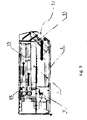
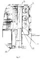
- Figs. 1-3 show the hood cooperating with a combi steamer.
- the hood has a generally rectangular housing 1 with a front hood 12 comprising an air inlet with installed filters 13. Behind the air inlet there is a suction chamber 2. Above the suction chamber 2 there is a radial fan 3 with a rotor with a vertical axis of rotation.
- a steam condenser in the form of an air-air (steam) heat exchanger 4 is arranged around the radial fan 3.
- the heat exchanger 4 is in the form of a coil 5 shaped as a coiled cylindrical pipe, equipped with an inlet opening 7 for supplying steam from the oven inside and an outlet opening 8 for draining the condensate.
- the upper part of the housing 1 comprises exhaust vents 14 through which the cooling air drawn in by the radial fan 3 is expelled.
- the coil 5 shown in Fig. 4 is in the form of a cylindrical pipe with an external finning 6 shaped as a square thread or in the form of rings.
- the coil 5 surrounding the radial fan 3 is shaped as a pipe coiled in a helix, and its inlet opening 7 is arranged above the outlet opening 8 and is located in the upper part of the heat exchanger 4.
- Such shape of the heat exchanger 4 results in gravitational condensate and steam flows from the inlet opening 7 towards the outlet opening 8.
- the pitch of the coil helix 5 can be from 0 to 1.5 of the coil diameter. In the case the coil 5 is not coiled in a helix ( Fig.
- the heat exchanger 4 can be composed of one or more such elements connected by a common collector.
- the heat exchanger4 is in the form of a multi-turn coil 5 in the form of one, continuous element.
- the heat exchanger 4 consists of three independent coils 5 connected by a common collector 9, but the heat exchanger4 can also have the form of a coil 5 made as a single continuous section of pipe.
- the steam supplying inlet openings 7 and the outlet openings 8 through which the condensate or possibly the uncondensed steam residues escape, are connected by a cylindrical common collector 9, arranged vertically, which is illustrated in more detail in Fig. 7 .
- the collector 9 is divided from above by a baffle 11 extending downwards to the condensate tray at the bottom of the collector 9.
- the baffle 11 divides the collector 9 into two spaces separating the inlet openings 7 from the outlet openings 8. In other words, on one side of the baffle 11 there are only inlet openings 7, and on the other side the outlet openings 8 only.
- a connector 10 is provided, which enters the space inside the collector 10 on the side of the inlet openings so that the upper part of the connector 10 defines the overflow level for the condensate coming out through the outlet openings 8 and accumulating in the tray on the collector bottom 9.
- the baffle 11 together with the condensate accumulating in the tray prevent the steam coming out through the outlet openings 8 from getting back into the inlet openings 7 for the steam coming out from the oven.
- the collector 9 is connected to exhaust funnels 15, through which the uncondensed steam, after passing through the coil 5, is discharged outside, wherein the exhaust funnel connection 15 is provided in the collector 9 on the side of outlet openings 8, above the overflow level.
- the air entering the hood passes through the filters 13 installed on the air inlet in the front hood 12, and then still cool (at ambient temperature) passes through the radial fan 3 and comes out of it, evenly feeding the heat exchanger 4, which is wrapped spirally around the radial fan 3. Positioning the radial fan 3 in the airflow upstream the heat exchanger 4 protects it from overheating.
Landscapes
- Engineering & Computer Science (AREA)
- Mechanical Engineering (AREA)
- General Engineering & Computer Science (AREA)
- Physics & Mathematics (AREA)
- Thermal Sciences (AREA)
- Geometry (AREA)
- Chemical & Material Sciences (AREA)
- Combustion & Propulsion (AREA)
- Life Sciences & Earth Sciences (AREA)
- Food Science & Technology (AREA)
- Heat-Exchange Devices With Radiators And Conduit Assemblies (AREA)
- Commercial Cooking Devices (AREA)
Applications Claiming Priority (2)
| Application Number | Priority Date | Filing Date | Title |
|---|---|---|---|
| PL428229A PL237178B1 (pl) | 2018-12-18 | 2018-12-18 | Pochłaniacz pary ze skraplaczem do pieca gastronomicznego, zwłaszcza pieca konwekcyjno-parowego |
| PCT/PL2019/050070 WO2020130861A1 (en) | 2018-12-18 | 2019-12-02 | Hood with condenser for commercial oven, particularly combination steam-convection oven |
Publications (2)
| Publication Number | Publication Date |
|---|---|
| EP3899374A1 EP3899374A1 (en) | 2021-10-27 |
| EP3899374B1 true EP3899374B1 (en) | 2022-12-07 |
Family
ID=69375980
Family Applications (1)
| Application Number | Title | Priority Date | Filing Date |
|---|---|---|---|
| EP19845728.5A Active EP3899374B1 (en) | 2018-12-18 | 2019-12-02 | Hood with condenser for commercial oven, particularly combination steam-convection oven |
Country Status (4)
| Country | Link |
|---|---|
| US (1) | US12022835B2 (pl) |
| EP (1) | EP3899374B1 (pl) |
| PL (2) | PL237178B1 (pl) |
| WO (1) | WO2020130861A1 (pl) |
Families Citing this family (4)
| Publication number | Priority date | Publication date | Assignee | Title |
|---|---|---|---|---|
| CN111820730A (zh) * | 2020-07-13 | 2020-10-27 | 广东美的厨房电器制造有限公司 | 用于烹饪设备的冷凝装置和具有其的烹饪设备 |
| CN112640926B (zh) * | 2020-10-12 | 2023-05-09 | 新疆恒远中汇彩印包装股份有限公司 | 一种抽拉式智能加工设备 |
| US12379161B2 (en) * | 2020-10-26 | 2025-08-05 | “Retech” Spolka Z Ograniczona Odpowiedzialnoscia | Steam condenser with heat exchanger and a cooking oven with such steam condenser |
| CN116807242B (zh) * | 2023-06-30 | 2026-03-03 | 纯米科技(上海)股份有限公司 | 一种冷凝结构及蒸烤设备 |
Family Cites Families (10)
| Publication number | Priority date | Publication date | Assignee | Title |
|---|---|---|---|---|
| US4071935A (en) * | 1975-08-07 | 1978-02-07 | Stainless Equipment Company | Method of making heat exchanger |
| DE4423557C2 (de) | 1994-07-05 | 2001-02-01 | Wiesheu Gmbh | Ofen zur Wärmebehandlung von Lebensmitteln |
| DE29708079U1 (de) * | 1997-04-25 | 1997-07-10 | Daub, Helmut, 75196 Remchingen | Dampfkondensierer, insbesondere für die Backtechnik |
| DE19959237C1 (de) * | 1999-12-08 | 2001-07-05 | Wiesheu Gmbh | Vorrichtung zum Kondensieren von Dampf |
| DE20317601U1 (de) | 2003-11-14 | 2005-01-27 | Eloma Gmbh Bedarfsartikel Zur Gemeinschaftsverpflegung | Kondensationsvorrichtung für die Abluft eines Gargerätes |
| ES2310109B1 (es) * | 2007-01-17 | 2009-12-03 | Dobra Industrial, S.A. | Horno y metodo de coccion y deshumidificacion de pan parcialmente precocido o de deshumidificacion de pan cocido. |
| EP2384626A1 (en) * | 2010-05-05 | 2011-11-09 | RETECH Spólka z o.o. | Steam condenser for a steam oven with convection heating |
| US9016082B2 (en) * | 2010-06-04 | 2015-04-28 | Trane International Inc. | Condensing unit desuperheater |
| US9557082B1 (en) * | 2014-05-13 | 2017-01-31 | Sa Vent, Llc | Apparatus for converting hot air and steam emissions into cooler air and condensate |
| EP3299730B1 (en) * | 2016-09-21 | 2019-07-31 | STEELFORM Srl | Heat exchanger for gas cooking oven |
-
2018
- 2018-12-18 PL PL428229A patent/PL237178B1/pl unknown
-
2019
- 2019-12-02 EP EP19845728.5A patent/EP3899374B1/en active Active
- 2019-12-02 US US17/415,825 patent/US12022835B2/en active Active
- 2019-12-02 PL PL19845728.5T patent/PL3899374T3/pl unknown
- 2019-12-02 WO PCT/PL2019/050070 patent/WO2020130861A1/en not_active Ceased
Also Published As
| Publication number | Publication date |
|---|---|
| PL3899374T3 (pl) | 2023-03-27 |
| EP3899374A1 (en) | 2021-10-27 |
| PL237178B1 (pl) | 2021-03-22 |
| WO2020130861A1 (en) | 2020-06-25 |
| US20220132867A1 (en) | 2022-05-05 |
| PL428229A1 (pl) | 2020-06-29 |
| US12022835B2 (en) | 2024-07-02 |
Similar Documents
| Publication | Publication Date | Title |
|---|---|---|
| US12022835B2 (en) | Hood with condenser for commercial oven, particularly combination steam-convection oven | |
| US3834133A (en) | Direct contact condenser having an air removal system | |
| US3828575A (en) | Compact heating and cooling system | |
| EP3093579A1 (en) | Condensing boiler | |
| CA1198947A (en) | Air-cooled steam condenser | |
| CN111839251B (zh) | 烹饪设备的冷凝装置及烹饪设备 | |
| EP3088597A1 (en) | Clothes dryer | |
| EP0073560A1 (en) | Fuel-fired fluid heating appliance | |
| US20160320072A1 (en) | Direct-heating fan oven | |
| EP3410053A1 (en) | Air-cooled heat exchanger | |
| EP3088598A1 (en) | Clothes dryer | |
| JP6238763B2 (ja) | 空気調和機の室内機及び空気調和機 | |
| CN111503672A (zh) | 一种带有烹饪装置的集成灶 | |
| US4130111A (en) | Ventilating system | |
| CN111820730A (zh) | 用于烹饪设备的冷凝装置和具有其的烹饪设备 | |
| EP2384626A1 (en) | Steam condenser for a steam oven with convection heating | |
| CN105899904B (zh) | 立式直管逆流冷凝器 | |
| US20170082298A1 (en) | Extractor hood for professional ovens for cooking food | |
| US9429339B2 (en) | Domestic gas-fired water heater condensing flue system | |
| US20170082301A1 (en) | Professional hot air recirculation oven for cooking food | |
| US7575178B2 (en) | Heat recovery apparatus | |
| US3192906A (en) | Boilers for reducing temperature gradient and improving water circulation | |
| EP4022226A1 (en) | Dehumidifier apparatus | |
| CN217907421U (zh) | 烹饪器具 | |
| EP2499438B1 (en) | Heat exchanger with improved exhaust gas discharge device |
Legal Events
| Date | Code | Title | Description |
|---|---|---|---|
| STAA | Information on the status of an ep patent application or granted ep patent |
Free format text: STATUS: UNKNOWN |
|
| STAA | Information on the status of an ep patent application or granted ep patent |
Free format text: STATUS: THE INTERNATIONAL PUBLICATION HAS BEEN MADE |
|
| PUAI | Public reference made under article 153(3) epc to a published international application that has entered the european phase |
Free format text: ORIGINAL CODE: 0009012 |
|
| STAA | Information on the status of an ep patent application or granted ep patent |
Free format text: STATUS: REQUEST FOR EXAMINATION WAS MADE |
|
| 17P | Request for examination filed |
Effective date: 20210708 |
|
| AK | Designated contracting states |
Kind code of ref document: A1 Designated state(s): AL AT BE BG CH CY CZ DE DK EE ES FI FR GB GR HR HU IE IS IT LI LT LU LV MC MK MT NL NO PL PT RO RS SE SI SK SM TR |
|
| DAV | Request for validation of the european patent (deleted) | ||
| DAX | Request for extension of the european patent (deleted) | ||
| GRAP | Despatch of communication of intention to grant a patent |
Free format text: ORIGINAL CODE: EPIDOSNIGR1 |
|
| STAA | Information on the status of an ep patent application or granted ep patent |
Free format text: STATUS: GRANT OF PATENT IS INTENDED |
|
| INTG | Intention to grant announced |
Effective date: 20220926 |
|
| GRAS | Grant fee paid |
Free format text: ORIGINAL CODE: EPIDOSNIGR3 |
|
| GRAA | (expected) grant |
Free format text: ORIGINAL CODE: 0009210 |
|
| STAA | Information on the status of an ep patent application or granted ep patent |
Free format text: STATUS: THE PATENT HAS BEEN GRANTED |
|
| AK | Designated contracting states |
Kind code of ref document: B1 Designated state(s): AL AT BE BG CH CY CZ DE DK EE ES FI FR GB GR HR HU IE IS IT LI LT LU LV MC MK MT NL NO PL PT RO RS SE SI SK SM TR |
|
| REG | Reference to a national code |
Ref country code: GB Ref legal event code: FG4D |
|
| REG | Reference to a national code |
Ref country code: CH Ref legal event code: EP Ref country code: AT Ref legal event code: REF Ref document number: 1536518 Country of ref document: AT Kind code of ref document: T Effective date: 20221215 |
|
| REG | Reference to a national code |
Ref country code: DE Ref legal event code: R096 Ref document number: 602019022994 Country of ref document: DE |
|
| REG | Reference to a national code |
Ref country code: IE Ref legal event code: FG4D |
|
| REG | Reference to a national code |
Ref country code: LT Ref legal event code: MG9D |
|
| REG | Reference to a national code |
Ref country code: NL Ref legal event code: MP Effective date: 20221207 |
|
| PG25 | Lapsed in a contracting state [announced via postgrant information from national office to epo] |
Ref country code: SE Free format text: LAPSE BECAUSE OF FAILURE TO SUBMIT A TRANSLATION OF THE DESCRIPTION OR TO PAY THE FEE WITHIN THE PRESCRIBED TIME-LIMIT Effective date: 20221207 Ref country code: NO Free format text: LAPSE BECAUSE OF FAILURE TO SUBMIT A TRANSLATION OF THE DESCRIPTION OR TO PAY THE FEE WITHIN THE PRESCRIBED TIME-LIMIT Effective date: 20230307 Ref country code: LT Free format text: LAPSE BECAUSE OF FAILURE TO SUBMIT A TRANSLATION OF THE DESCRIPTION OR TO PAY THE FEE WITHIN THE PRESCRIBED TIME-LIMIT Effective date: 20221207 Ref country code: FI Free format text: LAPSE BECAUSE OF FAILURE TO SUBMIT A TRANSLATION OF THE DESCRIPTION OR TO PAY THE FEE WITHIN THE PRESCRIBED TIME-LIMIT Effective date: 20221207 Ref country code: ES Free format text: LAPSE BECAUSE OF FAILURE TO SUBMIT A TRANSLATION OF THE DESCRIPTION OR TO PAY THE FEE WITHIN THE PRESCRIBED TIME-LIMIT Effective date: 20221207 |
|
| REG | Reference to a national code |
Ref country code: AT Ref legal event code: MK05 Ref document number: 1536518 Country of ref document: AT Kind code of ref document: T Effective date: 20221207 |
|
| PG25 | Lapsed in a contracting state [announced via postgrant information from national office to epo] |
Ref country code: RS Free format text: LAPSE BECAUSE OF FAILURE TO SUBMIT A TRANSLATION OF THE DESCRIPTION OR TO PAY THE FEE WITHIN THE PRESCRIBED TIME-LIMIT Effective date: 20221207 Ref country code: LV Free format text: LAPSE BECAUSE OF FAILURE TO SUBMIT A TRANSLATION OF THE DESCRIPTION OR TO PAY THE FEE WITHIN THE PRESCRIBED TIME-LIMIT Effective date: 20221207 Ref country code: HR Free format text: LAPSE BECAUSE OF FAILURE TO SUBMIT A TRANSLATION OF THE DESCRIPTION OR TO PAY THE FEE WITHIN THE PRESCRIBED TIME-LIMIT Effective date: 20221207 Ref country code: GR Free format text: LAPSE BECAUSE OF FAILURE TO SUBMIT A TRANSLATION OF THE DESCRIPTION OR TO PAY THE FEE WITHIN THE PRESCRIBED TIME-LIMIT Effective date: 20230308 |
|
| PG25 | Lapsed in a contracting state [announced via postgrant information from national office to epo] |
Ref country code: NL Free format text: LAPSE BECAUSE OF FAILURE TO SUBMIT A TRANSLATION OF THE DESCRIPTION OR TO PAY THE FEE WITHIN THE PRESCRIBED TIME-LIMIT Effective date: 20221207 |
|
| PG25 | Lapsed in a contracting state [announced via postgrant information from national office to epo] |
Ref country code: SM Free format text: LAPSE BECAUSE OF FAILURE TO SUBMIT A TRANSLATION OF THE DESCRIPTION OR TO PAY THE FEE WITHIN THE PRESCRIBED TIME-LIMIT Effective date: 20221207 Ref country code: RO Free format text: LAPSE BECAUSE OF FAILURE TO SUBMIT A TRANSLATION OF THE DESCRIPTION OR TO PAY THE FEE WITHIN THE PRESCRIBED TIME-LIMIT Effective date: 20221207 Ref country code: PT Free format text: LAPSE BECAUSE OF FAILURE TO SUBMIT A TRANSLATION OF THE DESCRIPTION OR TO PAY THE FEE WITHIN THE PRESCRIBED TIME-LIMIT Effective date: 20230410 Ref country code: EE Free format text: LAPSE BECAUSE OF FAILURE TO SUBMIT A TRANSLATION OF THE DESCRIPTION OR TO PAY THE FEE WITHIN THE PRESCRIBED TIME-LIMIT Effective date: 20221207 Ref country code: AT Free format text: LAPSE BECAUSE OF FAILURE TO SUBMIT A TRANSLATION OF THE DESCRIPTION OR TO PAY THE FEE WITHIN THE PRESCRIBED TIME-LIMIT Effective date: 20221207 |
|
| PG25 | Lapsed in a contracting state [announced via postgrant information from national office to epo] |
Ref country code: SK Free format text: LAPSE BECAUSE OF FAILURE TO SUBMIT A TRANSLATION OF THE DESCRIPTION OR TO PAY THE FEE WITHIN THE PRESCRIBED TIME-LIMIT Effective date: 20221207 Ref country code: IS Free format text: LAPSE BECAUSE OF FAILURE TO SUBMIT A TRANSLATION OF THE DESCRIPTION OR TO PAY THE FEE WITHIN THE PRESCRIBED TIME-LIMIT Effective date: 20230407 Ref country code: AL Free format text: LAPSE BECAUSE OF FAILURE TO SUBMIT A TRANSLATION OF THE DESCRIPTION OR TO PAY THE FEE WITHIN THE PRESCRIBED TIME-LIMIT Effective date: 20221207 |
|
| REG | Reference to a national code |
Ref country code: DE Ref legal event code: R097 Ref document number: 602019022994 Country of ref document: DE |
|
| PLBE | No opposition filed within time limit |
Free format text: ORIGINAL CODE: 0009261 |
|
| STAA | Information on the status of an ep patent application or granted ep patent |
Free format text: STATUS: NO OPPOSITION FILED WITHIN TIME LIMIT |
|
| PG25 | Lapsed in a contracting state [announced via postgrant information from national office to epo] |
Ref country code: DK Free format text: LAPSE BECAUSE OF FAILURE TO SUBMIT A TRANSLATION OF THE DESCRIPTION OR TO PAY THE FEE WITHIN THE PRESCRIBED TIME-LIMIT Effective date: 20221207 |
|
| 26N | No opposition filed |
Effective date: 20230908 |
|
| PG25 | Lapsed in a contracting state [announced via postgrant information from national office to epo] |
Ref country code: SI Free format text: LAPSE BECAUSE OF FAILURE TO SUBMIT A TRANSLATION OF THE DESCRIPTION OR TO PAY THE FEE WITHIN THE PRESCRIBED TIME-LIMIT Effective date: 20221207 |
|
| PG25 | Lapsed in a contracting state [announced via postgrant information from national office to epo] |
Ref country code: IT Free format text: LAPSE BECAUSE OF FAILURE TO SUBMIT A TRANSLATION OF THE DESCRIPTION OR TO PAY THE FEE WITHIN THE PRESCRIBED TIME-LIMIT Effective date: 20221207 |
|
| PG25 | Lapsed in a contracting state [announced via postgrant information from national office to epo] |
Ref country code: BG Free format text: LAPSE BECAUSE OF FAILURE TO SUBMIT A TRANSLATION OF THE DESCRIPTION OR TO PAY THE FEE WITHIN THE PRESCRIBED TIME-LIMIT Effective date: 20221207 |
|
| PG25 | Lapsed in a contracting state [announced via postgrant information from national office to epo] |
Ref country code: BG Free format text: LAPSE BECAUSE OF FAILURE TO SUBMIT A TRANSLATION OF THE DESCRIPTION OR TO PAY THE FEE WITHIN THE PRESCRIBED TIME-LIMIT Effective date: 20221207 |
|
| PG25 | Lapsed in a contracting state [announced via postgrant information from national office to epo] |
Ref country code: CY Free format text: LAPSE BECAUSE OF FAILURE TO SUBMIT A TRANSLATION OF THE DESCRIPTION OR TO PAY THE FEE WITHIN THE PRESCRIBED TIME-LIMIT; INVALID AB INITIO Effective date: 20191202 |
|
| PG25 | Lapsed in a contracting state [announced via postgrant information from national office to epo] |
Ref country code: HU Free format text: LAPSE BECAUSE OF FAILURE TO SUBMIT A TRANSLATION OF THE DESCRIPTION OR TO PAY THE FEE WITHIN THE PRESCRIBED TIME-LIMIT; INVALID AB INITIO Effective date: 20191202 |
|
| PG25 | Lapsed in a contracting state [announced via postgrant information from national office to epo] |
Ref country code: TR Free format text: LAPSE BECAUSE OF FAILURE TO SUBMIT A TRANSLATION OF THE DESCRIPTION OR TO PAY THE FEE WITHIN THE PRESCRIBED TIME-LIMIT Effective date: 20221207 |
|
| PGFP | Annual fee paid to national office [announced via postgrant information from national office to epo] |
Ref country code: LU Payment date: 20251121 Year of fee payment: 7 |
|
| REG | Reference to a national code |
Ref country code: CH Ref legal event code: U11 Free format text: ST27 STATUS EVENT CODE: U-0-0-U10-U11 (AS PROVIDED BY THE NATIONAL OFFICE) Effective date: 20260101 |
|
| PGFP | Annual fee paid to national office [announced via postgrant information from national office to epo] |
Ref country code: DE Payment date: 20251120 Year of fee payment: 7 |
|
| PGFP | Annual fee paid to national office [announced via postgrant information from national office to epo] |
Ref country code: GB Payment date: 20251120 Year of fee payment: 7 |
|
| PGFP | Annual fee paid to national office [announced via postgrant information from national office to epo] |
Ref country code: MC Payment date: 20251127 Year of fee payment: 7 |
|
| PGFP | Annual fee paid to national office [announced via postgrant information from national office to epo] |
Ref country code: FR Payment date: 20251120 Year of fee payment: 7 |
|
| PGFP | Annual fee paid to national office [announced via postgrant information from national office to epo] |
Ref country code: BE Payment date: 20251121 Year of fee payment: 7 |
|
| PGFP | Annual fee paid to national office [announced via postgrant information from national office to epo] |
Ref country code: IE Payment date: 20251121 Year of fee payment: 7 Ref country code: CZ Payment date: 20251125 Year of fee payment: 7 |
|
| PGFP | Annual fee paid to national office [announced via postgrant information from national office to epo] |
Ref country code: PL Payment date: 20251120 Year of fee payment: 7 |
|
| PGFP | Annual fee paid to national office [announced via postgrant information from national office to epo] |
Ref country code: CH Payment date: 20260101 Year of fee payment: 7 |