EP3899367B1 - Flachdachreaktor für chemical-looping-verbrennung - Google Patents
Flachdachreaktor für chemical-looping-verbrennung Download PDFInfo
- Publication number
- EP3899367B1 EP3899367B1 EP19817702.4A EP19817702A EP3899367B1 EP 3899367 B1 EP3899367 B1 EP 3899367B1 EP 19817702 A EP19817702 A EP 19817702A EP 3899367 B1 EP3899367 B1 EP 3899367B1
- Authority
- EP
- European Patent Office
- Prior art keywords
- combustion
- reactor
- particles
- lower chamber
- gas
- Prior art date
- Legal status (The legal status is an assumption and is not a legal conclusion. Google has not performed a legal analysis and makes no representation as to the accuracy of the status listed.)
- Active
Links
Images

Classifications
-
- F—MECHANICAL ENGINEERING; LIGHTING; HEATING; WEAPONS; BLASTING
- F23—COMBUSTION APPARATUS; COMBUSTION PROCESSES
- F23C—METHODS OR APPARATUS FOR COMBUSTION USING FLUID FUEL OR SOLID FUEL SUSPENDED IN A CARRIER GAS OR AIR
- F23C10/00—Fluidised bed combustion apparatus
- F23C10/18—Details; Accessories
-
- F—MECHANICAL ENGINEERING; LIGHTING; HEATING; WEAPONS; BLASTING
- F23—COMBUSTION APPARATUS; COMBUSTION PROCESSES
- F23C—METHODS OR APPARATUS FOR COMBUSTION USING FLUID FUEL OR SOLID FUEL SUSPENDED IN A CARRIER GAS OR AIR
- F23C99/00—Subject-matter not provided for in other groups of this subclass
-
- F—MECHANICAL ENGINEERING; LIGHTING; HEATING; WEAPONS; BLASTING
- F23—COMBUSTION APPARATUS; COMBUSTION PROCESSES
- F23C—METHODS OR APPARATUS FOR COMBUSTION USING FLUID FUEL OR SOLID FUEL SUSPENDED IN A CARRIER GAS OR AIR
- F23C10/00—Fluidised bed combustion apparatus
- F23C10/005—Fluidised bed combustion apparatus comprising two or more beds
-
- F—MECHANICAL ENGINEERING; LIGHTING; HEATING; WEAPONS; BLASTING
- F23—COMBUSTION APPARATUS; COMBUSTION PROCESSES
- F23C—METHODS OR APPARATUS FOR COMBUSTION USING FLUID FUEL OR SOLID FUEL SUSPENDED IN A CARRIER GAS OR AIR
- F23C2900/00—Special features of, or arrangements for combustion apparatus using fluid fuels or solid fuels suspended in air; Combustion processes therefor
- F23C2900/99008—Unmixed combustion, i.e. without direct mixing of oxygen gas and fuel, but using the oxygen from a metal oxide, e.g. FeO
-
- Y—GENERAL TAGGING OF NEW TECHNOLOGICAL DEVELOPMENTS; GENERAL TAGGING OF CROSS-SECTIONAL TECHNOLOGIES SPANNING OVER SEVERAL SECTIONS OF THE IPC; TECHNICAL SUBJECTS COVERED BY FORMER USPC CROSS-REFERENCE ART COLLECTIONS [XRACs] AND DIGESTS
- Y02—TECHNOLOGIES OR APPLICATIONS FOR MITIGATION OR ADAPTATION AGAINST CLIMATE CHANGE
- Y02E—REDUCTION OF GREENHOUSE GAS [GHG] EMISSIONS, RELATED TO ENERGY GENERATION, TRANSMISSION OR DISTRIBUTION
- Y02E20/00—Combustion technologies with mitigation potential
- Y02E20/34—Indirect CO2mitigation, i.e. by acting on non CO2directly related matters of the process, e.g. pre-heating or heat recovery
Definitions
- the present invention relates to the field of combustion of hydrocarbon feedstocks by chemical loop redox (CLC) operating in a fluidized bed, and more specifically relates to a CLC combustion reactor operating in a fluidized bed particularly well suited to the combustion of solid hydrocarbon feedstocks. or liquids.
- CLC chemical loop redox
- Chemical loop combustion, or Chemical Looping Combustion (CLC) process in its Anglo-Saxon terminology is a process consisting of implementing redox reactions of an active mass, typically a metal oxide, to decompose the combustion reaction of a hydrocarbon feedstock in two successive reactions: a first oxidation reaction of the active mass in contact with an oxidizing gas, typically air, in at least one oxidation zone, and a second reaction of reduction of the active mass in contact with the charge whose combustion is desired in at least one combustion zone.
- an active mass typically a metal oxide
- the active redox mass which releases part of the oxygen it contains upon contact with the charge in the combustion zone, thus plays the role of oxygen transporter between said combustion zone and the oxidation zone. where it is oxidized again.
- This solid material is in the form of fluidizable particles, belonging to groups A, B or C of the Geldart classification which is based on the size of the particles and their density difference with the gas, and often to group B.
- the particles are brought into contact in the reaction zones, with either the oxidizing gas or the feed, in the form of fluidized beds, and are generally transported from one zone to another in a fluidized form.
- the set of particles transported in a fluidized form is commonly called a circulating or transported fluidized bed.
- oxidizing gas typically air (or water vapor)
- oxidation reactor or air reactor a first reaction zone
- oxidation reactor or air reactor a second reaction zone
- a solid hydrocarbon feedstock e.g. coal, coke, petroleum coke called “pet-coke” in English, biomass, tar sands, household waste
- liquid e.g. fuel oil, bitumen, diesel, gasoline, shale oil, etc.
- gaseous e.g.: natural gas, syngas, biogas, shale gas
- the oxygen transported by the particles of the active mass fuels the combustion of the charge. This results in a gaseous effluent formed by the combustion of the charge and a flow of reduced particles.
- the particles are returned to the air reactor to be re-oxidized, thus closing the loop.
- the CLC process makes it possible to produce energy (steam, electricity, etc.) by recovering the heat released by combustion reactions while facilitating the capture of carbon dioxide (CO 2 ) emitted during combustion thanks to the production of smoke rich in CO 2 .
- the capture of CO 2 can in fact be done after condensation of the water vapor and compression of the fumes, and it can then be stored, for example in a deep aquifer, or be valorized, for example by using it for improve the performance of oil operations in enhanced oil recovery (EOR) or gas recovery (EGR) processes.
- EOR enhanced oil recovery
- EGR gas recovery
- the CLC process can also allow the production of synthesis gas, or even hydrogen, by controlling combustion and implementing the purifications required downstream of the combustion process.
- nitrogen flow very rich in nitrogen, which is the depleted air obtained following the oxidation of the active mass in the air reactor.
- this nitrogen flow can be used in various applications, particularly in the oil industry. It can for example be used in refineries as an inert gas in various oil refining processes or for the treatment of produced water, or as a gas injected into the subsoil in EOR processes.
- Different fluidization regimes can be implemented in the different units of the CLC installation, in particular in the oxidation and reduction reactors operating in a fluidized bed.
- the fluidization regime applied depends in fact on the operation to be carried out (combustion of the charge, oxidation of the particles of the oxygen carrier, transport of the particles, solid/solid separation, solid/gas separation) and the type of charge treated.
- the combustion of a solid charge itself in the form of particles requires a greater contact time with the particles of the oxygen carrier than the combustion of a gaseous charge, which generally results in the implemented in the combustion reactor of a zone comprising a dense fluidized bed, operating according to a heterogeneous fluidization regime corresponding to a so-called bubbling bed (presence of bubbles in the bed) or turbulent (preferred flow regime), in which the particles of the oxygen carrier and the solid charge are brought into contact for a first combustion step consisting essentially of gasification of the solid charge.
- a second stage is generally necessary to move towards total combustion, with the bringing into contact of the particles of the oxygen carrier and the gasified charge.
- This second step is generally carried out in the first reaction zone, and can also be carried out in a second reaction zone comprising a diluted fluidized bed, operating according to a transported fluidization regime (corresponding to the regime of circulating fluidized beds) involving higher gas velocities.
- This reaction zone generally corresponds to a part of the reactor forming a substantially elongated and vertical conduit commonly called "riser", a term taken from Anglo-Saxon terminology and commonly used by those skilled in the art.
- iser substantially elongated and vertical conduit commonly called "riser”, a term taken from Anglo-Saxon terminology and commonly used by those skilled in the art.
- Such a configuration involving a first combustion zone in a dense fluidized bed surmounted by a second combustion zone of riser type operating in a dense fluidized bed is for example described in the patent application WO11151535 relating to a CLC process specific to solid hydrocarbon feedstocks.
- a riser type reactor may be sufficient to achieve combustion of the charge.
- the flow goes from the bubble regime (bubbling bed which is a dense bed), to the spooling regime, known as 'slugging' in English (depending on the height and diameter of the bed), at the turbulent regime, at the rapid fluidization regime (circulating bed) then at the transport regime.
- the fluidization regime may differ depending on the group of particles, they all reach, whatever their group, a turbulent fluidization regime, then a rapid fluidization regime, followed by a transport regime when the speed of the gas increases.
- the pistoning regime appears when the diameter of the bubbles becomes comparable to the diameter of the column: with group B particles, the bubbles grow in size as they rise in the reactor, their size being able to reach the diameter of the reactor in the extreme.
- the regime reached is that of pistoning, generating 'plug' flows. Large bubbles burst on the surface of the bed or on the wall, with dense agglomerates of solid carried in their wake, generating strong flow heterogeneities, and resulting in strong pressure fluctuations and vibrations.
- the turbulent regime is particularly interesting for industrial processes because it presents a much more homogeneous mixture of phases and a very significant mass and thermal transfer, compared to the bubbling and pistoning regimes. It is a regime which corresponds to strong agitation of the particles: as the fluidization speed increases, the size and number of bubbles gradually increase and the agitation of the suspension becomes more and more violent. This agitation is produced by the rise of the bubbles and by the fact that they carry part of the suspension in their wake. At high speeds, the shape of the bubbles becomes irregular. However, even if the large bubbles formed do not reach the diameter of the reactor, they can cause large pressure fluctuations and vibrations within the bed, typically when they break within the bed, on the surface of the bed and in the walls of the reactor.
- the pistoning regime as well as the formation of large bubbles are therefore undesirable for several reasons: the mixture of solid and gas is less good (less homogeneous), the homogeneity of the reactor temperature is no longer ensured, and the strong fluctuations pressure and vibrations on the walls and bottom of the reactor are harmful to the mechanical strength of the reactor.
- the present invention proposes to provide another solution dedicated to CLC to reduce the problems linked to the pistoning phenomenon, in particular to limit the strong pressure fluctuations in the combustion reactor and in particular in the elongated part of the reactor ("riser").
- the present invention aims to provide a CLC combustion reactor making it possible to limit the undesirable effects generated by the implementation of pistoning and turbulence fluidization regimes in the reactor, in particular to limit the strong pressure fluctuations caused by the formation of large bubbles and their bursting. It thus aims to preserve the mechanical strength of the combustion reactor, to ensure temperature homogeneity in the reactor, as well as to ensure homogeneity of the gas/particle mixture in the reactor with a view to optimal combustion.
- the lower enclosure comprises a main injection system for a main fluidization gas positioned at the base of the lower enclosure.
- the lower enclosure further comprises a secondary injection system for a secondary fluidization gas positioned at the top of the lower enclosure.
- the lower enclosure further comprises a tertiary injection system for a tertiary fluidization gas positioned between the main injection system and the top of the lower enclosure, configured to control the level of the dense bed .
- the upper part of the combustion reactor comprises a segment penetrating into the lower part of the enclosure with a height h preferably between 0.01xH and 0.3xH, H being the height of the enclosure lower part of the combustion reactor.
- the ratio of the passage section of the lower enclosure to the passage section of the upper enclosure is between 2 and 15, and preferably between 3 and 10.
- the lower and upper enclosures of the reactor have a parallelepiped shape, preferably rectangular.
- the hydrocarbon feedstock is a solid feedstock, preferably chosen from coal, coke, petroleum coke, biomass, bituminous sands and household waste and a separation of unburnt particles is carried out and particles of the redox active mass contained in a gas mixture comprising combustion gases coming from the upper enclosure of the combustion reactor into a solid/solid particle separator, the particles of the redox active mass are sent thus separated towards the oxidation reactor, and the unburnt particles, optionally separated from the combustion gases in at least one gas-solid separation stage, are recycled into the combustion reactor.
- the superficial speed of the gas in the lower enclosure of the combustion reactor is between 0.3 m/s and 3 m/s, and in which the superficial speed of the gas in the upper enclosure of the reactor combustion is between 3 m/s and 15 m/s.
- the temperature in the combustion reactor is between 600°C and 1400°C, preferably between 800°C and 1000°C.
- a secondary fluidization gas is injected at the top of the lower enclosure of the combustion reactor, preferably forming a jet in a direction forming an angle ⁇ of between 0 and 90° with the vertical.
- the flow rate of the secondary fluidization gas is between 0.02 ⁇ Q GP and 0.2 ⁇ Q GP , Q GP being the flow rate of the main fluidization gas.
- a tertiary fluidization gas is injected into a zone of the dense bed in the lower enclosure of the combustion reactor so as to control the level of the dense bed.
- the particles of the redox active mass belong to group B according to the Geldart classification.
- the object of the invention is to propose a combustion reactor for chemical loop combustion of specific geometry adapted for the combustion of solid or liquid hydrocarbon feedstocks, and preferably solid feedstocks, making it possible to limit the strong pressure fluctuations linked to the presence of large bubbles and the pistoning phenomenon encountered in the turbulent regime of fluidized beds.
- oxygen carrier material or abbreviated “active mass”
- oxygen carrier solid or “oxygen carrier”
- oxygen carrier or abbreviated “active mass”
- the redox mass is said to be active in relation to its reactive capacities, in the sense that it is able to play its role as an oxygen transporter in the CLC process by capturing and releasing oxygen.
- the oxidation reactor also called air reactor
- the reduction reactor also called fuel reactor or combustion reactor
- the reactors operate in a fluidized bed and the active mass circulates between the oxidation reactor and the reduction reactor. Circulating fluidized bed technology is used to allow the continuous passage of the active mass from its oxidized state in the oxidation reactor to its reduced state in the reduction reactor.
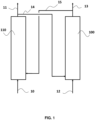
- FIG. 1 is a diagram representing the general operating principle of chemical loop combustion. It is in no way limiting to the CLC installation and process integrating the combustion reactor according to the invention.
- a reduced oxygen carrier 15 is brought into contact with an air flow 10 in a reaction zone 110 previously defined as the oxidation reactor (or air reactor). This results in a depleted air flow 11 and a flow of re-oxidized particles 14.
- the flow of oxidized oxygen carrier particles 14 is transferred into the reduction zone 100 previously defined as the combustion reactor (or combustion reactor). reduction).
- the flow of particles 14 is brought into contact with a fuel 12, which is a hydrocarbon feedstock. This results in a combustion effluent 13 and a flow of reduced oxygen carrier particles 15.
- the representation of the figure 1 does not understand the various equipment that can be part of the CLC unit, for solid/gas separation, solid/solid separation, heat exchange, pressurization, gas sealing between reactors (e.g. siphons), solid storage, control of solid flows (e.g. mechanical or pneumatic valves) or possible recirculation of material around the oxidation and combustion reactors.
- the hydrocarbon feedstock 12 is brought into cocurrent contact with the active redox mass in the form of particles to carry out the combustion of said feedstock by reduction of the active redox mass.
- the active redox mass M x O y M representing a metal, is reduced to the state M x O y-2n-m/2 , via the hydrocarbon charge C n H m , which is correlatively oxidized in CO 2 and H 2 O, according to reaction (1) below, or possibly in a CO + H 2 mixture depending on the proportions used.
- Total combustion of the hydrocarbon feedstock is generally targeted.
- the combustion of the charge in contact with the active mass is carried out at a temperature generally between 600°C and 1400°C, preferably between 800°C and 1000°C.
- the contact time varies depending on the type of fuel filler used. It typically varies between 1 second and 20 minutes, for example preferably between 1 minute and 10 minutes, and more preferably between 1 minute and 8 minutes for a solid or liquid load, and for example preferably from 1 to 20 seconds for a load gaseous.
- a mixture comprising the gases resulting from combustion and the particles of the active mass is evacuated to the top of the reduction zone 100.
- Gas/solid separation means (not shown), such as a cyclone, make it possible to separate the combustion gas 13 of the solid particles of the active mass in their most reduced state 15.
- a solid/solid separation device making it possible to separate the particles of The unburned particles of the active mass can be used at the outlet of the combustion reactor.
- This type of separator can be associated with one or more gas/solid separators arranged downstream of the solid/solid separator.
- the particles of the active mass having remained in the combustion reactor, and separated from the combustion gases, are sent to the oxidation zone 110 to be re-oxidized.
- the unburned products can be recycled to the reduction reactor 100.
- the active mass is restored to its oxidized state MxOy in contact with an oxidizing gas 10, typically air or water vapor, and preferably air, depending on the reaction (2) below, before returning to the reduction reactor 100, and after being separated from the oxygen-depleted gas 11, typically so-called “depleted” air, evacuated at the top of the oxidation reactor 110.
- an oxidizing gas 10 typically air or water vapor, and preferably air, depending on the reaction (2) below
- n and m respectively represent the number of carbon and hydrogen atoms having reacted with the active mass in the combustion reactor.
- the temperature in the oxidation reactor is generally between 600°C and 1400°C, preferably between 800 and 1000°C.
- the active mass passing alternately from its oxidized form to its reduced form and vice versa, describes an oxidation-reduction cycle.
- the treated hydrocarbon feedstocks can be solid or liquid hydrocarbon feedstocks.
- the solid loads can be chosen from coal, coke, petroleum coke (“pet-coke” in English), biomass, tar sands and household waste.
- Liquid fillers can be chosen from petroleum, bitumen, diesel, gasoline.
- the treated hydrocarbon filler is a solid filler, as stated above.
- the redox mass may be composed of metal oxides, such as for example oxides of Fe, Ti, Ni, Cu, Mn, Co, V, alone or in a mixture, which may come from ores (for example ilmenite or pyrolusite) or be synthetic (for example copper oxide particles supported on CuO/Al 2 O 3 alumina or nickel oxide particles supported on NiO/Al 2 O 4 alumina, preferably oxide particles of copper supported on alumina CuO/Al 2 O 3 ), with or without a binder, and has the required redox properties and the characteristics necessary for the implementation of fluidization.
- the oxygen storage capacity of the redox mass is advantageously, depending on the type of material, between 0.5% and 15% by weight.
- the quantity of oxygen actually transferred by the metal oxide is between 0.5% and 3% by weight, which allows only a fraction of the total oxygen transfer capacity to be used, ideally less than 30% of it in order to limit the risks of mechanical aging or particle agglomeration.
- Using only a fraction of the oxygen transport capacity also has the advantage that the fluidized bed acts as a thermal ballast and thus smooths out temperature variations along the path of the oxygen carrier.
- the active mass is in the form of fluidizable particles, belonging to groups A, B, C or D of the Geldart classification, alone or in combination.
- the particles of the redox active mass belong to group B of the Geldart classification.
- the group B particles used have a particle size such that more than 90% of the particles have a size between 100 ⁇ m and 500 ⁇ m, preferably between 150 ⁇ m and 300 ⁇ m.
- the particles of the oxidoreductive active mass which may be metallic oxides, synthetic or natural minerals, supported or not, have a density of between 1000 kg/m 3 and 5000 kg/m 3 and preferably between 1200 kg/m 3 m 3 and 4000 kg/m 3 .
- nickel oxide particles supported on alumina generally have a grain density of between 2500 and 3500 kg/m 3 depending on the porosity of the support and the oxide content. of nickel, typically around 3200 kg/m 3 .
- Ilmenite an ore combining titanium and iron (iron oxide and titanium), has a density of 4700 kg/m 3 .
- the active redox mass can undergo an activation phase so as to increase its reactive capacities, which may consist of a temperature rise phase, preferably progressive, and preferably under an oxidizing atmosphere (for example under air).
- the oxidation and combustion reactors operate in a fluidized bed. They each include at least one fluidization gas injection system.
- the fluidization gas may be CO 2 , which may be CO 2 produced during combustion and recycled, or water vapor.
- the fluidization gas is an oxidizing gas, preferably air.
- the oxidation reactor preferably comprises a transported fluidized bed.
- the speed of the gas is between 2 m/s and 15 m/s, and preferably between 3 m/s and 10 m/s.
- such a reactor can have a diameter of between 1 m and 6 m for a height of between 10 m and 30 m.
- the combustion reactor 100 is configured to include a dense bed and a transported bed arrangement.
- the combustion reactor 100 comprises a lower enclosure comprising a dense fluidized bed, surmounted by an upper enclosure comprising a transported fluidized bed.
- the upper enclosure has a smaller passage section than that of the lower enclosure, making it possible to accelerate and transport the gas-particle mixture leaving the lower enclosure.
- the speed of the gas in the lower enclosure is between 0.3 m/s and 3 m/s.
- the speed of the gas in the upper enclosure of the combustion reactor is between 3 m/s and 15m/s.
- the combustion reactor 100 can have a diameter of between 1 and 10 m, for a height of between 3 m and 40 m.
- the section ratio between the lower enclosure and the upper enclosure is between 2 and 15, preferably from 3 to 10.
- dense fluidized bed we mean a bubbling bed or a turbulent bed.
- the volume fraction of solid in such a dense fluidized bed is generally between 0.25 and 0.50.
- diluted fluidized bed we mean a transported bed.
- the solid volume fraction is generally less than 0.25.
- the geometry of the reactors can be parallelepiped, cylindrical or any other three-dimensional geometry preferably comprising a symmetry of revolution.
- cylindrical we refer to a cylinder of revolution.
- the combustion reactor in particular the lower and upper enclosures, has a parallelepiped shape, preferably rectangular.
- the lower and upper enclosures of the combustion reactor have such a shape.
- This form of reactor is well suited to industrial implementation of CLC involving large equipment.
- large size we mean reactors so the passage section is expressed in tens of m 2 , over heights of several tens of meters.
- this particular geometry also has the advantage of simplifying the possible installation of refractory materials on the internal face in order to protect against strong temperatures the generally metallic wall of the reactor enclosure.
- Such refractory materials can be used in combination with standard steels in order to limit manufacturing costs.
- layers of reinforced refractory cement typically having thicknesses generally between 2 and 50 cm, generally close to 20 cm, on the internal faces exposed to flow and high temperatures make it possible to use standard steels for the external parts of the reactor.
- Bricks can also be used as refractory material on the internal faces of the walls of the reactor enclosure.
- the materials used to make the reactors and its constituent elements can be chosen from refractory materials, for example of the refractory concrete, refractory brick or ceramic type, high temperature steels, for example of the Hastelloy ® , Incoloy ® , Inconel ® or Manaurite ® type, or conventional steels, for example of the stainless steel or carbon steel type combined with refractory materials or combined with cooling means such as tubes in which a heat transfer fluid circulates.
- the lower enclosure comprises a dense fluidized bed and the upper enclosure comprises a transported fluidized bed.
- a geometry is well suited to the combustion of solid or liquid loads, in particular solids, which require a sufficiently long contact time with the particles of the active mass to tend towards total combustion, and which involve a first phase of gasification of the solid or liquid charge (in a dense fluidized bed), followed by combustion of the gasified charge (in a dense fluidized bed and in a transported fluidized bed).
- the gasification of the charge contributes to increasing the speed of the gas in the lower enclosure with a substantially constant passage section. This increase in gas speed is also achieved due to the narrower passage section in the upper enclosure.
- the size of the bubbles can become very large, until approaching the size of the passage section of the lower enclosure, characterizing the pistoning phenomenon during the speed of the lower enclosure.
- pistoning transient between the bubbling bed regime and the turbulent regime and pose the problems of pressure fluctuation, vibration, temperature heterogeneity and solid/gas mixture as already described, and harmful to the integrity of the installation CLC and the performance of the CLC process.
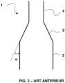
- a known combustion reactor 1 is illustrated schematically in figure 2 .
- Such a combustion reactor is for example described in the application WO11151535 . It comprises a lower enclosure 2 comprising a dense bed and an upper enclosure 4 comprising a diluted bed.
- the upper enclosure 4 has an elongated shape and a passage section strictly smaller than that of the lower enclosure, for example less by at least 25% than that of the lower enclosure, or even by at least 50%.
- This upper enclosure 4 is a “riser”.
- the change in section makes it possible to increase the speed between the lower enclosure 2 and the upper enclosure 4 and to ensure the transition between dense phase flow and dilute phase flow.
- the lower enclosure 2 comprises a supply conduit for the hydrocarbon feed, a particle supply conduit for the active mass coming from the oxidation reactor, a system for injecting a fluidization gas positioned at the base of enclosure 2, at a level lower than that of the supply conduits for the hydrocarbon feed and the particles of the active mass, and allowing the formation of the dense bed.
- a fluidization gas is introduced by specific means which may be perforated plates arranged downstream of a distributor which may be a wind box supplied by a conduit for supplying said gas. These plates can be inclined at an angle generally between 30° and 70° relative to the horizontal and can leave in the central part a free space for the flow of particles, making it possible to draw off part of the particles through the distributor. particles sedimenting in this zone and consisting mainly of agglomerated ashes.
- the lower enclosure 2 may also include one or more pipes for recycling unburned particles connected to solid/solid separation systems (elutriation separation devices) and/or gas/solid (e.g. cyclones).
- solid/solid separation systems elutriation separation devices
- gas/solid e.g. cyclones
- the upper enclosure 4 has at its top an evacuation for the gas mixture comprising the combustion gases and the particles of the active mass, and possibly unburnt particles and ashes.
- the upper enclosure 4 can also include a supply of active mass particles.
- the combustion of the gaseous effluent from the lower enclosure 2 can be carried out.
- This gaseous effluent includes the gasified solid charge, partially converted, or even completely converted.
- the average residence time of the gas in this upper enclosure 4 is generally between 1 second and 20 seconds, the average residence time of the solids varying between 2 seconds and 1 minute. Under these conditions, and taking into account the dilute nature of the flow and the presence of particles of the active mass of oxygen, the reactions are essentially reactions between the gas phase (gasified charge) and the particles of the active mass .
- a conduit of variable section 3 makes it possible to make the junction between the lower enclosure 2 and the upper enclosure 4, and allows the evacuation of gaseous effluents and particles entrained towards the upper enclosure 4.
- this conduit is a cone 3.
- the wall of cone 3 forms a non-zero angle ⁇ with the walls of the lower and upper enclosures, i.e. with the vertical.
- the bubbles carrying the agglomerates of solids slide on the conical wall 3, concentrate at the entrance to the upper enclosure 4, and then cause, when they burst, strong pressure fluctuations.
- agglomerates of solids we mean particles which have slightly agglomerated together to form larger clusters. These clusters can be carried away by the bubbles.
- the entrainment of agglomerates in the upper enclosure 4 creates a flow which is not uniform, also causing pressure fluctuations in the upper enclosure 4.
- the entrainment of agglomerates of solid particles in the enclosure upper 4 is harmful because these can in turn cause pistoning phenomena in the upper enclosure 4, a phenomenon all the more likely to occur as the section is reduced.
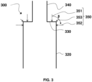
- This intermediate part constitutes a sort of flat ceiling for the lower enclosure 320.
- internal wall of the intermediate part 330 is meant the face of the wall forming this intermediate part 330 located inside the enclosure 320, in contact with the fluidized bed.
- the intermediate part 330 comprises an external wall, ie a face of the wall forming this intermediate part 330 located outside the enclosure 320, which is slightly curved to facilitate the anchoring of a material refractory.
- the curvature can be of elliptical shape, and have a ratio of the semi-axes (ratio between the major axis and the minor axis) preferably between 2 and 30, and more preferably between 5 and 20.
- the shape of the external wall can be of different shape, such as those described in the normative document NFE81-100 specific to rounded bottoms. Examples of refractory materials have been given above in relation to the description of the installation and the CLC process illustrated in figure 1 .
- a flat roof is well preserved for the lower enclosure inside the reactor, that is to say a right angle for the junction inside the reactor (internal wall of the intermediate part 330 ) between the side wall of the lower enclosure 320 and the side wall of the upper enclosure 340.
- the combustion reactor according to the invention may comprise other elements similar to those described above for the combustion reactor 1 according to the prior art, not shown on the Figure 3 .
- the lower enclosure 320 may also include one or more recycling lines for unburned particles connected to solid/solid separation systems (elutriation separation devices) and/or gas/solid (e.g. cyclones).
- solid/solid separation systems elutriation separation devices
- gas/solid e.g. cyclones
- the upper enclosure 340 advantageously includes an evacuation at its top for the gas mixture comprising the combustion gases and the particles of the active mass, and possibly particles of unburned matter and ashes.
- the upper enclosure 340 may also include a supply of active mass particles.
- the upper enclosure 340 may have a passage section lower than the passage section of the lower enclosure 320 by at least 25%, or even lower by at least 50%.
- the passage from the section of the lower enclosure 320 to the reduced section of the upper enclosure 340 makes it possible to increase the speed of the flow between the two enclosures and to ensure the transition between the flow in dense phase and the dilute phase flow.
- the combustion of the gaseous effluent from the lower enclosure 320 can be carried out.
- This gaseous effluent includes the gasified solid charge, partially converted, or even completely converted.
- the average residence time of the gas in this upper enclosure is generally between 1 second and 20 seconds, the average residence time of the solids varying between 2 seconds and 1 minute. Under these conditions, and taking into account the dilute nature of the flow and the presence of particles of the active mass of oxygen, the reactions are essentially reactions between the gas phase (gasified charge) and the particles of the active mass .
- the upper enclosure comprises a diluted fluidized bed having a solid volume fraction of less than 0.10.
- the lower enclosure 320 further comprises a secondary injection system 350 for a secondary fluidization gas positioned at the top of the lower enclosure 320.
- the secondary fluidization gas can be injected at the top of the lower enclosure 320 of the combustion reactor 300, and preferably form at least one jet in the enclosure in a direction forming an angle ⁇ of between 0 and 90 ° (values included) with the vertical.
- the secondary fluidization gas can be injected at the top of the lower enclosure 320 of the combustion reactor 300, and preferably form at least one jet in the enclosure in a direction forming an angle ⁇ of between 0 and 90 ° (values included) with the vertical.
- the flow rate of the secondary fluidization gas is less than 0.2 ⁇ Q GP , Q GP being the flow rate of the main fluidization gas.
- the flow rate of the secondary fluidization gas is between 0.02 ⁇ Q GP and 0.2 ⁇ Q GP , and more preferably between 0.05 ⁇ Q GP and 0.15 ⁇ Q GP .
- the lower enclosure further comprises a tertiary injection system (not shown) for a tertiary fluidization gas positioned between the main injection system and the top of the lower enclosure, configured to control the level of the dense bed
- a tertiary fluidization gas is thus injected into a zone of the dense bed in the lower enclosure of the combustion reactor so as to control the level of the dense bed, by affecting the entrainment of the solid particles.
- the disengagement zone is the diluted zone above the dense bed (between the interface of the dense bed and the top of the enclosure).
- this injection can be done so as to form at least one jet in the enclosure in a direction forming an angle between 90°, value included (horizontal direction), and 180°, value excluded, with the vertical. Jets in several of these directions can also be made.
- the main fluidization gas can be CO 2 , for example CO 2 produced during combustion and recycled, or water vapor.
- the other fluidization gases, secondary and tertiary, may be of the same nature as the main fluidization gas and come from the same source.
- a combustion reactor 400 according to a second embodiment of the invention is illustrated in the figure 4 , and is in every respect identical to the reactor 300 described above in relation to the Figure 3 , with the exception of the upper enclosure 440, which comprises a segment 441 penetrating into the lower part of the enclosure with a height h preferably between 0.01xH and 0.3xH, H being the height of the lower enclosure 320 of the combustion reactor.
- the height H of the lower enclosure 320 can be between 3 m and 40 m, for example be 20 m.
- the height of the upper enclosure 440 can be between 3 m and 40 m, for example be 20 m.
- the ratio of passage section of the lower enclosure to passage section of the upper enclosure can be between 2 and 15, and preferably between 3 and 10.
- the present invention also relates to the CLC installation comprising the combustion reactor according to the invention as described above, operating in a fluidized bed to carry out the combustion of said hydrocarbon feed in contact with the particles of the active mass of oxido- reduction, and comprising the oxidation reactor operating in a fluidized bed to oxidize the particles of the reduced redox active mass coming from the combustion reactor by contacting with an oxidizing gas. Details of such an installation have already been given in relation to the figure 1 .
- the gaseous effluent from the lower enclosure includes the gasified solid charge as well as the effluents from the combustion carried out in the lower enclosure.
- the upper enclosure of the combustion reactor also receives the particles of the active mass from the part lower, as well as possibly unburned particles and possibly fly ash, particularly in the case of combustion of solid loads.
- unburned particles we mean the particles of the solid hydrocarbon feed which have not undergone total combustion, and which therefore still contain hydrocarbon compounds.
- Ashes are incombustible elements resulting from the total combustion of solid fuel particles and for which the residence time in the combustion reactor has been sufficient.
- the ashes are essentially mineral in nature.
- They typically contain the following compounds: SiO 2 , Al 2 O 3 , Fe 2 O 3 , CaO, MgO, TiO 2 , K 2 O, Na 2 O, SO 3 , P 2 O 5 . They are characterized by a particle size and density lower than active mass particles (ie less than 100 ⁇ m) and often also lower than unburned particles.
- the particles of the redox active mass having remained in the combustion reactor are separated from the combustion gases by means of at least one solid/solid separator and /or solid/gas.
- Such separators are for example described in patent applications WO11151535 And WO11151537 .
- solid/solid separator we mean a device allowing the separation between two populations of solid particles: the particles of the oxygen carrier and the particles of unburned particles which leave the combustion reactor.
Landscapes
- Engineering & Computer Science (AREA)
- Chemical & Material Sciences (AREA)
- Combustion & Propulsion (AREA)
- Mechanical Engineering (AREA)
- General Engineering & Computer Science (AREA)
- Devices And Processes Conducted In The Presence Of Fluids And Solid Particles (AREA)
- Fluidized-Bed Combustion And Resonant Combustion (AREA)
Claims (15)
- Verbrennungsreaktor (100, 300, 400) für die Chemical-Looping-Combustion, der dafür ausgelegt ist, im Fließbettverfahren betrieben zu werden, wobei er Folgendes aufweist:- einen unteren Hohlraum (320), der einen ersten Reaktionsbereich für die Verbrennung einer kohlenwasserstoffartigen Charge in Gegenwart von Partikeln einer Redox-Wirkmasse bildet, wobei der untere Hohlraum (320) eine erste Seitenwand aufweist und dafür ausgelegt ist, ein dichtes Fließbett aufzuweisen;- einen oberen Hohlraum (340, 440) von länglicher Form, der weiterhin einen kleineren Strömungsquerschnitt als der Strömungsquerschnitt des unteren Hohlraums (320) hat, wobei er einen zweiten Reaktionsbereich für die Verbrennung des gasförmigen Stoffstroms bildet, welcher aus der Verbrennung im unteren Abschnitt stammt, wobei der obere Hohlraum (340, 440) eine zweite Seitenwand aufweist und dafür ausgelegt ist, ein verdünntes Fließbett aufzuweisen;- einen Zwischenabschnitt (330), welcher den unteren Hohlraum (320) mit dem oberen Hohlraum (340, 440) verbindet, wobei der Verbrennungsreaktor dadurch gekennzeichnet ist, dass der Zwischenabschnitt (330) eine Innenwand aufweist, die einen rechten Winkel mit der ersten Seitenwand des unteren Hohlraums (320) und mit der zweiten Seitenwand des oberen Hohlraums (340, 440) bildet.
- Reaktor nach Anspruch 1, wobei der untere Hohlraum (320) ein Haupteinleitungssystem aufweist, das für ein Hauptfluidisierungsgas bestimmt ist und an der Basis des unteren Hohlraums angeordnet ist.
- Reaktor nach Anspruch 2, wobei der untere Hohlraum (320) weiterhin ein Sekundäreinleitungssystem (350) aufweist, das für ein Sekundärfluidisierungsgas bestimmt ist und an der Spitze des unteren Hohlraums angeordnet ist.
- Reaktor nach einem beliebigen der Ansprüche 2 oder 3, wobei der untere Hohlraum (320) weiterhin ein Tertiäreinleitungssystem aufweist, das für ein Tertiärfluidisierungsgas bestimmt ist und zwischen dem Haupteinleitungssystem und der Spitze des unteren Hohlraums angeordnet ist, wobei es dafür ausgelegt ist, den Pegel des dichten Bettes zu steuern.
- Reaktor nach einem beliebigen der vorhergehenden Ansprüche, wobei der obere Abschnitt (440) des Verbrennungsreaktors einen Teilbereich (441) aufweist, welcher um eine Höhe h, die vorzugsweise im Bereich von 0,01×H bis 0,3×H liegt, in den unteren Abschnitt (320) des Hohlraums eindringt, wobei H die Höhe des unteren Hohlraums (320) des Verbrennungsreaktors ist.
- Reaktor nach einem beliebigen der vorhergehenden Ansprüche, wobei das Verhältnis des Strömungsquerschnitts des unteren Hohlraums (320) zum Strömungsquerschnitt des oberen Hohlraums (340, 440) im Bereich von 2 bis 15, und vorzugsweise von 3 bis 10, liegt.
- Reaktor nach einem beliebigen der vorhergehenden Ansprüche, wobei der untere (320) und der obere (340, 440) Hohlraum des Reaktors die Form eines Parallelepipeds, vorzugsweise eines Quaders, haben.
- Verfahren zur Chemical-Looping-Combustion einer kohlenwasserstoffartigen Charge, bei welchem ein Verbrennungsreaktor (100, 300, 400) gemäß einem beliebigen der Ansprüche 1 bis 7 zum Einsatz gebracht wird, wobei es die folgenden Schritte umfasst:- Inkontaktbringen von Partikeln einer Redox-Wirkmasse mit der kohlenwasserstoffartigen Charge in dem unteren Hohlraum (320) des Verbrennungsreaktors (100, 300, 400) innerhalb eines dichten Fließbetts, wie es durch Einleiten eines Hauptfluidisierungsgases gebildet wird;- Durchführen einer Verbrennung des gasförmigen Stoffstroms, welcher aus dem unteren Hohlraum (320) stammt, in Gegenwart von Partikeln der Redox-Wirkmasse im oberen Hohlraum (340, 440) des Verbrennungsreaktors, innerhalb eines verdünnten Fließbetts;- Durchführen einer Oxidation der Partikel der Redox-Wirkmasse, welche sich in dem Verbrennungsreaktor (100, 300, 400) befunden haben, innerhalb eines Oxidationsreaktors (110), welcher im Fließbettverfahren betrieben wird, woraufhin diese in den Verbrennungsreaktor (100, 300, 400) zurückgeleitet werden.
- Verfahren nach Anspruch 8, wobei es sich bei der kohlenwasserstoffartigen Charge um eine feststoffliche Charge handelt, die vorzugsweise aus Kohle, Koks, Petrolkoks, Biomasse, Ölsanden und Haushaltsabfällen ausgewählt ist, und wobei in einer Feststoff/Feststoff-Partikeltrennvorrichtung eine Trennung der unverbrannten Partikel und der Partikel der Redox-Wirkmasse durchgeführt wird, wie sie in einer Gasmischung enthalten sind, die Verbrennungsgase aufweist, welche aus dem oberen Hohlraum (340, 440) des Verbrennungsreaktors (100, 300, 400) stammen, um die Partikel der Redox-Wirkmasse, welche auf diese Weise abgetrennt wurden, dem Oxidationsreaktor (110) zuzuführen, und die unverbrannten Partikel, welche gegebenenfalls in mindestens einem Schritt der Gas/Feststoff-Trennung abgetrennt wurden, in den Verbrennungsreaktor (100, 300, 400) zurückzuführen.
- Verfahren nach einem beliebigen der Ansprüche 8 und 9, wobei die Oberflächengeschwindigkeit des Gases in dem unteren Hohlraum (320) des Verbrennungsreaktors im Bereich von 0,3 m/s bis 3 m/s liegt, und wobei die Oberflächengeschwindigkeit des Gases in dem oberen Hohlraum (340, 440) des Verbrennungsreaktors im Bereich von 3 m/s bis 15 m/s liegt.
- Verfahren nach einem beliebigen der Ansprüche 8 bis 10, wobei die Temperatur im Verbrennungsreaktor (100, 300, 400) im Bereich von 600 °C bis 1400 °C, vorzugsweise von 800 °C bis 1000 °C, liegt.
- Verfahren nach einem beliebigen der Ansprüche 8 bis 11, wobei ein Sekundärfluidisierungsgas an der Spitze des unteren Hohlraums (320) des Verbrennungsreaktors eingeleitet wird, wobei es vorzugsweise einen Strahl (351, 352, 353) gemäß einer Richtung bildet, welche mit der Vertikalen einen Winkel β im Bereich von 0 bis 90° bildet.
- Verfahren nach Anspruch 12, wobei die Flussrate des Sekundärfluidisierungsgases im Bereich von 0,02×QGP bis 0,2xQGP liegt, wobei QGP die Flussrate des Hauptfluidisierungsgases ist.
- Verfahren nach einem beliebigen der Ansprüche 8 bis 13, wobei in einen Bereich des dichten Bettes im unteren Hohlraum (320) des Verbrennungsreaktors (100, 300, 400) ein Tertiärfluidisierungsgas derart eingeleitet wird, dass der Pegel des dichten Bettes gesteuert wird.
- Verfahren nach einem beliebigen der Ansprüche 8 bis 14, wobei die Partikel der Redox-Wirkmasse gemäß der Klassifikation nach Geldart der Gruppe B angehören.
Applications Claiming Priority (2)
| Application Number | Priority Date | Filing Date | Title |
|---|---|---|---|
| FR1873092A FR3089827B1 (fr) | 2018-12-17 | 2018-12-17 | Réacteur de combustion en boucle chimique à toit plat |
| PCT/EP2019/084511 WO2020126704A1 (fr) | 2018-12-17 | 2019-12-10 | Réacteur de combustion en boucle chimique à toit plat |
Publications (2)
| Publication Number | Publication Date |
|---|---|
| EP3899367A1 EP3899367A1 (de) | 2021-10-27 |
| EP3899367B1 true EP3899367B1 (de) | 2024-02-07 |
Family
ID=66690513
Family Applications (1)
| Application Number | Title | Priority Date | Filing Date |
|---|---|---|---|
| EP19817702.4A Active EP3899367B1 (de) | 2018-12-17 | 2019-12-10 | Flachdachreaktor für chemical-looping-verbrennung |
Country Status (8)
| Country | Link |
|---|---|
| US (1) | US20220082249A1 (de) |
| EP (1) | EP3899367B1 (de) |
| CN (1) | CN113195974B (de) |
| CA (1) | CA3113863A1 (de) |
| ES (1) | ES2978362T3 (de) |
| FR (1) | FR3089827B1 (de) |
| PL (1) | PL3899367T3 (de) |
| WO (1) | WO2020126704A1 (de) |
Families Citing this family (4)
| Publication number | Priority date | Publication date | Assignee | Title |
|---|---|---|---|---|
| EP3963261B1 (de) * | 2019-04-29 | 2025-05-28 | Improbed AB | Verfahren zum betrieb eines wirbelbettkessels |
| FR3118134B1 (fr) | 2020-12-18 | 2022-12-16 | Ifp Energies Now | Procédé et réacteur de combustion en boucle chimique comportant une fluidisation étagée |
| US11752480B2 (en) * | 2021-02-04 | 2023-09-12 | Babcock & Wilcox Company | Apparatus for enclosing a chemical looping process |
| CN114574250B (zh) * | 2022-04-14 | 2023-05-02 | 河南大学 | 一种生物质化学链气化制清洁合成气的方法及装置 |
Family Cites Families (17)
| Publication number | Priority date | Publication date | Assignee | Title |
|---|---|---|---|---|
| DE2447603C3 (de) * | 1974-10-05 | 1979-12-13 | Bergwerksverband Gmbh, 4300 Essen | Vorrichtung zur kontinuierlichen Reaktivierung von kohlenstoffhaltigen Adsorptionsmitteln |
| DE2624302C2 (de) * | 1976-05-31 | 1987-04-23 | Metallgesellschaft Ag, 6000 Frankfurt | Verfahren zur Durchführung exothermer Prozesse |
| JPS541437A (en) * | 1977-06-07 | 1979-01-08 | Agency Of Ind Science & Technol | Multi stage liquid combustion method and device of coal |
| JPS57209635A (en) * | 1981-06-22 | 1982-12-23 | Res Assoc Residual Oil Process<Rarop> | Method and apparatus for preventing slagging of particulate material |
| FI79403C (fi) * | 1984-06-01 | 1989-12-11 | Ahlstroem Oy | Foerbraenningsmetod. |
| JPH0639216Y2 (ja) * | 1988-12-27 | 1994-10-12 | 宇部興産株式会社 | 流動床ボイラ |
| DE102005037111A1 (de) * | 2005-08-03 | 2007-02-15 | Alstom Technology Ltd. | Zirkulierender Wirbelschichtreaktor |
| CN101049927B (zh) * | 2007-04-18 | 2010-11-10 | 清华大学 | 连续化生产碳纳米管的方法及装置 |
| FR2960940B1 (fr) * | 2010-06-02 | 2015-08-07 | Inst Francais Du Petrole | Procede de combustion en boucle chimique avec une zone de reaction integrant une zone de separation gaz-solide et installation utilisant un tel procede |
| FR2960941B1 (fr) | 2010-06-02 | 2014-11-14 | Inst Francais Du Petrole | Dispositif de separation de particules pour une boucle de combustion chimique |
| AT509586B8 (de) * | 2010-06-11 | 2011-12-15 | Univ Wien Tech | Verbessertes wirbelschichtreaktorsystem |
| US8841495B2 (en) | 2011-04-18 | 2014-09-23 | Gas Technology Institute | Bubbling bed catalytic hydropyrolysis process utilizing larger catalyst particles and smaller biomass particles featuring an anti-slugging reactor |
| WO2012155054A1 (en) * | 2011-05-11 | 2012-11-15 | The Ohio State University | Systems for converting fuel |
| AT513490B1 (de) * | 2012-11-12 | 2014-05-15 | Univ Wien Tech | Wirbelschichtreaktorsystem |
| US20160030904A1 (en) * | 2013-03-13 | 2016-02-04 | Ohio State Innovation Foundation | Distributing secondary solids in packed moving bed reactors |
| FR3007104B1 (fr) * | 2013-06-13 | 2019-01-25 | IFP Energies Nouvelles | Procede et installation de combustion par oxydo-reduction en boucle chimique d'une charge hydrocarbonee solide |
| FR3022611B1 (fr) * | 2014-06-19 | 2016-07-08 | Ifp Energies Now | Procede et installation de combustion par oxydo-reduction en boucle chimique avec un controle des echanges de chaleur |
-
2018
- 2018-12-17 FR FR1873092A patent/FR3089827B1/fr active Active
-
2019
- 2019-12-10 ES ES19817702T patent/ES2978362T3/es active Active
- 2019-12-10 WO PCT/EP2019/084511 patent/WO2020126704A1/fr not_active Ceased
- 2019-12-10 CN CN201980083295.4A patent/CN113195974B/zh active Active
- 2019-12-10 PL PL19817702.4T patent/PL3899367T3/pl unknown
- 2019-12-10 CA CA3113863A patent/CA3113863A1/fr active Pending
- 2019-12-10 EP EP19817702.4A patent/EP3899367B1/de active Active
- 2019-12-10 US US17/414,784 patent/US20220082249A1/en active Pending
Also Published As
| Publication number | Publication date |
|---|---|
| FR3089827B1 (fr) | 2021-01-01 |
| EP3899367A1 (de) | 2021-10-27 |
| ES2978362T3 (es) | 2024-09-11 |
| PL3899367T3 (pl) | 2024-07-08 |
| CN113195974B (zh) | 2025-02-14 |
| CA3113863A1 (fr) | 2020-06-25 |
| FR3089827A1 (fr) | 2020-06-19 |
| WO2020126704A1 (fr) | 2020-06-25 |
| CN113195974A (zh) | 2021-07-30 |
| US20220082249A1 (en) | 2022-03-17 |
Similar Documents
| Publication | Publication Date | Title |
|---|---|---|
| EP3899367B1 (de) | Flachdachreaktor für chemical-looping-verbrennung | |
| CA2767073C (fr) | Procede et installation de combustion en boucle chimique avec controle independant de la circulation des solides | |
| CA2799139C (fr) | Dispositif de separation de particules pour une boucle de combustion chimique | |
| EP3158264B1 (de) | Verfahren und vorrichtung für chemical-looping-combustion mit steuerung des wärmaustausches | |
| CA2850612A1 (fr) | Procede de combustion en boucle chimique avec elimination des cendres et fines en sortie de la zone d'oxydation et installation utilisant un tel procede | |
| EP4374109B1 (de) | Clc-anlage und verfahren mit rückgewinnung von durch einen sauerstoffträger erzeugtem gasförmigem sauerstoff | |
| EP3230415B1 (de) | Verfahren und anlage für chemische oxidation-reduktion von kohlenwasserstoffgas als ausgangsmaterial mit in situ katalytische reformierung des ausgangsmaterials | |
| EP3827201B1 (de) | Clc-anlage mit einem feststoff-feststoff-separator mit mitteln zur verteilung eines gas-feststoff-gemisches | |
| EP4449018B1 (de) | Kreislaufverbrennungsanlage und verfahren mit einem zyklon-luftreaktor | |
| FR2882046A1 (fr) | Installation de production d'hydrogene ou de gaz de synthese par gazeification | |
| FR3118134A1 (fr) | Procédé et réacteur de combustion en boucle chimique comportant une fluidisation étagée | |
| EP3853525B1 (de) | Vorrichtung und verfahren zur chemical-looping-verbrennung mit einem partikelabscheider mit geneigtem einlasskanal | |
| CA3238175A1 (fr) | Cyclone pour une installation et un procede de combustion en boucle chimique muni d'une conduite d'arrivee a parois inclinees et injection de gaz | |
| WO2020126703A1 (fr) | Installation clc comportant un separateur solide/solide integrant une enceinte cyclonique | |
| FR3030018A1 (fr) | Installation et procede de combustion par oxydo-reduction en boucle chimique d'une charge hydrocarbonee gazeuse avec pre-reformage catalytique de la charge |
Legal Events
| Date | Code | Title | Description |
|---|---|---|---|
| STAA | Information on the status of an ep patent application or granted ep patent |
Free format text: STATUS: UNKNOWN |
|
| STAA | Information on the status of an ep patent application or granted ep patent |
Free format text: STATUS: THE INTERNATIONAL PUBLICATION HAS BEEN MADE |
|
| PUAI | Public reference made under article 153(3) epc to a published international application that has entered the european phase |
Free format text: ORIGINAL CODE: 0009012 |
|
| STAA | Information on the status of an ep patent application or granted ep patent |
Free format text: STATUS: REQUEST FOR EXAMINATION WAS MADE |
|
| 17P | Request for examination filed |
Effective date: 20210719 |
|
| AK | Designated contracting states |
Kind code of ref document: A1 Designated state(s): AL AT BE BG CH CY CZ DE DK EE ES FI FR GB GR HR HU IE IS IT LI LT LU LV MC MK MT NL NO PL PT RO RS SE SI SK SM TR |
|
| DAV | Request for validation of the european patent (deleted) | ||
| DAX | Request for extension of the european patent (deleted) | ||
| RAP1 | Party data changed (applicant data changed or rights of an application transferred) |
Owner name: TOTALENERGIES ONETECH Owner name: IFP ENERGIES NOUVELLES |
|
| GRAP | Despatch of communication of intention to grant a patent |
Free format text: ORIGINAL CODE: EPIDOSNIGR1 |
|
| STAA | Information on the status of an ep patent application or granted ep patent |
Free format text: STATUS: GRANT OF PATENT IS INTENDED |
|
| INTG | Intention to grant announced |
Effective date: 20230824 |
|
| GRAS | Grant fee paid |
Free format text: ORIGINAL CODE: EPIDOSNIGR3 |
|
| GRAA | (expected) grant |
Free format text: ORIGINAL CODE: 0009210 |
|
| STAA | Information on the status of an ep patent application or granted ep patent |
Free format text: STATUS: THE PATENT HAS BEEN GRANTED |
|
| AK | Designated contracting states |
Kind code of ref document: B1 Designated state(s): AL AT BE BG CH CY CZ DE DK EE ES FI FR GB GR HR HU IE IS IT LI LT LU LV MC MK MT NL NO PL PT RO RS SE SI SK SM TR |
|
| REG | Reference to a national code |
Ref country code: GB Ref legal event code: FG4D Free format text: NOT ENGLISH |
|
| REG | Reference to a national code |
Ref country code: CH Ref legal event code: EP |
|
| REG | Reference to a national code |
Ref country code: IE Ref legal event code: FG4D Free format text: LANGUAGE OF EP DOCUMENT: FRENCH |
|
| REG | Reference to a national code |
Ref country code: DE Ref legal event code: R096 Ref document number: 602019046250 Country of ref document: DE |
|
| REG | Reference to a national code |
Ref country code: LT Ref legal event code: MG9D |
|
| REG | Reference to a national code |
Ref country code: NL Ref legal event code: MP Effective date: 20240207 |
|
| PG25 | Lapsed in a contracting state [announced via postgrant information from national office to epo] |
Ref country code: IS Free format text: LAPSE BECAUSE OF FAILURE TO SUBMIT A TRANSLATION OF THE DESCRIPTION OR TO PAY THE FEE WITHIN THE PRESCRIBED TIME-LIMIT Effective date: 20240607 |
|
| PG25 | Lapsed in a contracting state [announced via postgrant information from national office to epo] |
Ref country code: LT Free format text: LAPSE BECAUSE OF FAILURE TO SUBMIT A TRANSLATION OF THE DESCRIPTION OR TO PAY THE FEE WITHIN THE PRESCRIBED TIME-LIMIT Effective date: 20240207 |
|
| PG25 | Lapsed in a contracting state [announced via postgrant information from national office to epo] |
Ref country code: GR Free format text: LAPSE BECAUSE OF FAILURE TO SUBMIT A TRANSLATION OF THE DESCRIPTION OR TO PAY THE FEE WITHIN THE PRESCRIBED TIME-LIMIT Effective date: 20240508 |
|
| REG | Reference to a national code |
Ref country code: AT Ref legal event code: MK05 Ref document number: 1655593 Country of ref document: AT Kind code of ref document: T Effective date: 20240207 |
|
| PG25 | Lapsed in a contracting state [announced via postgrant information from national office to epo] |
Ref country code: NL Free format text: LAPSE BECAUSE OF FAILURE TO SUBMIT A TRANSLATION OF THE DESCRIPTION OR TO PAY THE FEE WITHIN THE PRESCRIBED TIME-LIMIT Effective date: 20240207 Ref country code: HR Free format text: LAPSE BECAUSE OF FAILURE TO SUBMIT A TRANSLATION OF THE DESCRIPTION OR TO PAY THE FEE WITHIN THE PRESCRIBED TIME-LIMIT Effective date: 20240207 Ref country code: RS Free format text: LAPSE BECAUSE OF FAILURE TO SUBMIT A TRANSLATION OF THE DESCRIPTION OR TO PAY THE FEE WITHIN THE PRESCRIBED TIME-LIMIT Effective date: 20240507 |
|
| PG25 | Lapsed in a contracting state [announced via postgrant information from national office to epo] |
Ref country code: AT Free format text: LAPSE BECAUSE OF FAILURE TO SUBMIT A TRANSLATION OF THE DESCRIPTION OR TO PAY THE FEE WITHIN THE PRESCRIBED TIME-LIMIT Effective date: 20240207 |
|
| PG25 | Lapsed in a contracting state [announced via postgrant information from national office to epo] |
Ref country code: RS Free format text: LAPSE BECAUSE OF FAILURE TO SUBMIT A TRANSLATION OF THE DESCRIPTION OR TO PAY THE FEE WITHIN THE PRESCRIBED TIME-LIMIT Effective date: 20240507 Ref country code: NL Free format text: LAPSE BECAUSE OF FAILURE TO SUBMIT A TRANSLATION OF THE DESCRIPTION OR TO PAY THE FEE WITHIN THE PRESCRIBED TIME-LIMIT Effective date: 20240207 Ref country code: LT Free format text: LAPSE BECAUSE OF FAILURE TO SUBMIT A TRANSLATION OF THE DESCRIPTION OR TO PAY THE FEE WITHIN THE PRESCRIBED TIME-LIMIT Effective date: 20240207 Ref country code: IS Free format text: LAPSE BECAUSE OF FAILURE TO SUBMIT A TRANSLATION OF THE DESCRIPTION OR TO PAY THE FEE WITHIN THE PRESCRIBED TIME-LIMIT Effective date: 20240607 Ref country code: HR Free format text: LAPSE BECAUSE OF FAILURE TO SUBMIT A TRANSLATION OF THE DESCRIPTION OR TO PAY THE FEE WITHIN THE PRESCRIBED TIME-LIMIT Effective date: 20240207 Ref country code: GR Free format text: LAPSE BECAUSE OF FAILURE TO SUBMIT A TRANSLATION OF THE DESCRIPTION OR TO PAY THE FEE WITHIN THE PRESCRIBED TIME-LIMIT Effective date: 20240508 Ref country code: FI Free format text: LAPSE BECAUSE OF FAILURE TO SUBMIT A TRANSLATION OF THE DESCRIPTION OR TO PAY THE FEE WITHIN THE PRESCRIBED TIME-LIMIT Effective date: 20240207 Ref country code: BG Free format text: LAPSE BECAUSE OF FAILURE TO SUBMIT A TRANSLATION OF THE DESCRIPTION OR TO PAY THE FEE WITHIN THE PRESCRIBED TIME-LIMIT Effective date: 20240207 Ref country code: AT Free format text: LAPSE BECAUSE OF FAILURE TO SUBMIT A TRANSLATION OF THE DESCRIPTION OR TO PAY THE FEE WITHIN THE PRESCRIBED TIME-LIMIT Effective date: 20240207 |
|
| PG25 | Lapsed in a contracting state [announced via postgrant information from national office to epo] |
Ref country code: PT Free format text: LAPSE BECAUSE OF FAILURE TO SUBMIT A TRANSLATION OF THE DESCRIPTION OR TO PAY THE FEE WITHIN THE PRESCRIBED TIME-LIMIT Effective date: 20240607 |
|
| PG25 | Lapsed in a contracting state [announced via postgrant information from national office to epo] |
Ref country code: SE Free format text: LAPSE BECAUSE OF FAILURE TO SUBMIT A TRANSLATION OF THE DESCRIPTION OR TO PAY THE FEE WITHIN THE PRESCRIBED TIME-LIMIT Effective date: 20240207 Ref country code: PT Free format text: LAPSE BECAUSE OF FAILURE TO SUBMIT A TRANSLATION OF THE DESCRIPTION OR TO PAY THE FEE WITHIN THE PRESCRIBED TIME-LIMIT Effective date: 20240607 Ref country code: LV Free format text: LAPSE BECAUSE OF FAILURE TO SUBMIT A TRANSLATION OF THE DESCRIPTION OR TO PAY THE FEE WITHIN THE PRESCRIBED TIME-LIMIT Effective date: 20240207 |
|
| REG | Reference to a national code |
Ref country code: ES Ref legal event code: FG2A Ref document number: 2978362 Country of ref document: ES Kind code of ref document: T3 Effective date: 20240911 |
|
| PG25 | Lapsed in a contracting state [announced via postgrant information from national office to epo] |
Ref country code: DK Free format text: LAPSE BECAUSE OF FAILURE TO SUBMIT A TRANSLATION OF THE DESCRIPTION OR TO PAY THE FEE WITHIN THE PRESCRIBED TIME-LIMIT Effective date: 20240207 |
|
| PG25 | Lapsed in a contracting state [announced via postgrant information from national office to epo] |
Ref country code: SM Free format text: LAPSE BECAUSE OF FAILURE TO SUBMIT A TRANSLATION OF THE DESCRIPTION OR TO PAY THE FEE WITHIN THE PRESCRIBED TIME-LIMIT Effective date: 20240207 |
|
| PG25 | Lapsed in a contracting state [announced via postgrant information from national office to epo] |
Ref country code: CZ Free format text: LAPSE BECAUSE OF FAILURE TO SUBMIT A TRANSLATION OF THE DESCRIPTION OR TO PAY THE FEE WITHIN THE PRESCRIBED TIME-LIMIT Effective date: 20240207 Ref country code: EE Free format text: LAPSE BECAUSE OF FAILURE TO SUBMIT A TRANSLATION OF THE DESCRIPTION OR TO PAY THE FEE WITHIN THE PRESCRIBED TIME-LIMIT Effective date: 20240207 |
|
| PG25 | Lapsed in a contracting state [announced via postgrant information from national office to epo] |
Ref country code: SK Free format text: LAPSE BECAUSE OF FAILURE TO SUBMIT A TRANSLATION OF THE DESCRIPTION OR TO PAY THE FEE WITHIN THE PRESCRIBED TIME-LIMIT Effective date: 20240207 |
|
| PG25 | Lapsed in a contracting state [announced via postgrant information from national office to epo] |
Ref country code: SM Free format text: LAPSE BECAUSE OF FAILURE TO SUBMIT A TRANSLATION OF THE DESCRIPTION OR TO PAY THE FEE WITHIN THE PRESCRIBED TIME-LIMIT Effective date: 20240207 Ref country code: SK Free format text: LAPSE BECAUSE OF FAILURE TO SUBMIT A TRANSLATION OF THE DESCRIPTION OR TO PAY THE FEE WITHIN THE PRESCRIBED TIME-LIMIT Effective date: 20240207 Ref country code: RO Free format text: LAPSE BECAUSE OF FAILURE TO SUBMIT A TRANSLATION OF THE DESCRIPTION OR TO PAY THE FEE WITHIN THE PRESCRIBED TIME-LIMIT Effective date: 20240207 Ref country code: EE Free format text: LAPSE BECAUSE OF FAILURE TO SUBMIT A TRANSLATION OF THE DESCRIPTION OR TO PAY THE FEE WITHIN THE PRESCRIBED TIME-LIMIT Effective date: 20240207 Ref country code: DK Free format text: LAPSE BECAUSE OF FAILURE TO SUBMIT A TRANSLATION OF THE DESCRIPTION OR TO PAY THE FEE WITHIN THE PRESCRIBED TIME-LIMIT Effective date: 20240207 Ref country code: CZ Free format text: LAPSE BECAUSE OF FAILURE TO SUBMIT A TRANSLATION OF THE DESCRIPTION OR TO PAY THE FEE WITHIN THE PRESCRIBED TIME-LIMIT Effective date: 20240207 |
|
| REG | Reference to a national code |
Ref country code: DE Ref legal event code: R097 Ref document number: 602019046250 Country of ref document: DE |
|
| PG25 | Lapsed in a contracting state [announced via postgrant information from national office to epo] |
Ref country code: IT Free format text: LAPSE BECAUSE OF FAILURE TO SUBMIT A TRANSLATION OF THE DESCRIPTION OR TO PAY THE FEE WITHIN THE PRESCRIBED TIME-LIMIT Effective date: 20240207 |
|
| PLBE | No opposition filed within time limit |
Free format text: ORIGINAL CODE: 0009261 |
|
| STAA | Information on the status of an ep patent application or granted ep patent |
Free format text: STATUS: NO OPPOSITION FILED WITHIN TIME LIMIT |
|
| PG25 | Lapsed in a contracting state [announced via postgrant information from national office to epo] |
Ref country code: IT Free format text: LAPSE BECAUSE OF FAILURE TO SUBMIT A TRANSLATION OF THE DESCRIPTION OR TO PAY THE FEE WITHIN THE PRESCRIBED TIME-LIMIT Effective date: 20240207 |
|
| 26N | No opposition filed |
Effective date: 20241108 |
|
| PG25 | Lapsed in a contracting state [announced via postgrant information from national office to epo] |
Ref country code: SI Free format text: LAPSE BECAUSE OF FAILURE TO SUBMIT A TRANSLATION OF THE DESCRIPTION OR TO PAY THE FEE WITHIN THE PRESCRIBED TIME-LIMIT Effective date: 20240207 |
|
| PG25 | Lapsed in a contracting state [announced via postgrant information from national office to epo] |
Ref country code: MC Free format text: LAPSE BECAUSE OF FAILURE TO SUBMIT A TRANSLATION OF THE DESCRIPTION OR TO PAY THE FEE WITHIN THE PRESCRIBED TIME-LIMIT Effective date: 20240207 |
|
| REG | Reference to a national code |
Ref country code: CH Ref legal event code: PL |
|
| PG25 | Lapsed in a contracting state [announced via postgrant information from national office to epo] |
Ref country code: LU Free format text: LAPSE BECAUSE OF NON-PAYMENT OF DUE FEES Effective date: 20241210 |
|
| REG | Reference to a national code |
Ref country code: BE Ref legal event code: MM Effective date: 20241231 |
|
| PG25 | Lapsed in a contracting state [announced via postgrant information from national office to epo] |
Ref country code: BE Free format text: LAPSE BECAUSE OF NON-PAYMENT OF DUE FEES Effective date: 20241231 |
|
| PG25 | Lapsed in a contracting state [announced via postgrant information from national office to epo] |
Ref country code: CH Free format text: LAPSE BECAUSE OF NON-PAYMENT OF DUE FEES Effective date: 20241231 |
|
| PG25 | Lapsed in a contracting state [announced via postgrant information from national office to epo] |
Ref country code: IE Free format text: LAPSE BECAUSE OF NON-PAYMENT OF DUE FEES Effective date: 20241210 |
|
| PGFP | Annual fee paid to national office [announced via postgrant information from national office to epo] |
Ref country code: GB Payment date: 20251223 Year of fee payment: 7 |
|
| PGFP | Annual fee paid to national office [announced via postgrant information from national office to epo] |
Ref country code: NO Payment date: 20251218 Year of fee payment: 7 |
|
| PGFP | Annual fee paid to national office [announced via postgrant information from national office to epo] |
Ref country code: FR Payment date: 20251223 Year of fee payment: 7 |
|
| PGFP | Annual fee paid to national office [announced via postgrant information from national office to epo] |
Ref country code: PL Payment date: 20251128 Year of fee payment: 7 |
|
| PGFP | Annual fee paid to national office [announced via postgrant information from national office to epo] |
Ref country code: ES Payment date: 20260122 Year of fee payment: 7 |
|
| PGFP | Annual fee paid to national office [announced via postgrant information from national office to epo] |
Ref country code: DE Payment date: 20251229 Year of fee payment: 7 |