EP3899367B1 - Flat-roof chemical looping combustion reactor - Google Patents
Flat-roof chemical looping combustion reactor Download PDFInfo
- Publication number
- EP3899367B1 EP3899367B1 EP19817702.4A EP19817702A EP3899367B1 EP 3899367 B1 EP3899367 B1 EP 3899367B1 EP 19817702 A EP19817702 A EP 19817702A EP 3899367 B1 EP3899367 B1 EP 3899367B1
- Authority
- EP
- European Patent Office
- Prior art keywords
- combustion
- reactor
- particles
- lower chamber
- gas
- Prior art date
- Legal status (The legal status is an assumption and is not a legal conclusion. Google has not performed a legal analysis and makes no representation as to the accuracy of the status listed.)
- Active
Links
- 238000002485 combustion reaction Methods 0.000 title claims description 167
- 239000000126 substance Substances 0.000 title claims description 11
- 239000002245 particle Substances 0.000 claims description 119
- 239000007789 gas Substances 0.000 claims description 91
- 239000007787 solid Substances 0.000 claims description 81
- 238000005243 fluidization Methods 0.000 claims description 49
- 238000007254 oxidation reaction Methods 0.000 claims description 44
- 230000003647 oxidation Effects 0.000 claims description 38
- 150000002430 hydrocarbons Chemical class 0.000 claims description 31
- 239000004215 Carbon black (E152) Substances 0.000 claims description 30
- 229930195733 hydrocarbon Natural products 0.000 claims description 30
- 238000000034 method Methods 0.000 claims description 26
- 230000008569 process Effects 0.000 claims description 26
- 238000002347 injection Methods 0.000 claims description 24
- 239000007924 injection Substances 0.000 claims description 24
- 238000006243 chemical reaction Methods 0.000 claims description 21
- 230000009467 reduction Effects 0.000 claims description 21
- 238000000926 separation method Methods 0.000 claims description 17
- 239000000203 mixture Substances 0.000 claims description 12
- 239000000567 combustion gas Substances 0.000 claims description 11
- 239000002006 petroleum coke Substances 0.000 claims description 6
- 239000002028 Biomass Substances 0.000 claims description 5
- 239000003245 coal Substances 0.000 claims description 4
- 239000000571 coke Substances 0.000 claims description 4
- 239000010791 domestic waste Substances 0.000 claims description 4
- 229910052739 hydrogen Inorganic materials 0.000 claims description 3
- 230000000149 penetrating effect Effects 0.000 claims description 3
- 239000011269 tar Substances 0.000 claims 1
- 229910052760 oxygen Inorganic materials 0.000 description 25
- QVGXLLKOCUKJST-UHFFFAOYSA-N atomic oxygen Chemical compound [O] QVGXLLKOCUKJST-UHFFFAOYSA-N 0.000 description 24
- 239000001301 oxygen Substances 0.000 description 24
- 238000009434 installation Methods 0.000 description 11
- 239000007788 liquid Substances 0.000 description 10
- 230000015572 biosynthetic process Effects 0.000 description 7
- 230000005587 bubbling Effects 0.000 description 7
- 239000000446 fuel Substances 0.000 description 7
- 230000001590 oxidative effect Effects 0.000 description 7
- 235000002918 Fraxinus excelsior Nutrition 0.000 description 6
- 239000002956 ash Substances 0.000 description 6
- 239000011819 refractory material Substances 0.000 description 6
- XLYOFNOQVPJJNP-UHFFFAOYSA-N water Chemical compound O XLYOFNOQVPJJNP-UHFFFAOYSA-N 0.000 description 6
- 238000004519 manufacturing process Methods 0.000 description 5
- 229910000831 Steel Inorganic materials 0.000 description 4
- PNEYBMLMFCGWSK-UHFFFAOYSA-N aluminium oxide Inorganic materials [O-2].[O-2].[O-2].[Al+3].[Al+3] PNEYBMLMFCGWSK-UHFFFAOYSA-N 0.000 description 4
- 230000008901 benefit Effects 0.000 description 4
- 239000000945 filler Substances 0.000 description 4
- XEEYBQQBJWHFJM-UHFFFAOYSA-N iron Substances [Fe] XEEYBQQBJWHFJM-UHFFFAOYSA-N 0.000 description 4
- 239000000463 material Substances 0.000 description 4
- 229910044991 metal oxide Inorganic materials 0.000 description 4
- 239000003921 oil Substances 0.000 description 4
- 239000010959 steel Substances 0.000 description 4
- 229910018072 Al 2 O 3 Inorganic materials 0.000 description 3
- IJGRMHOSHXDMSA-UHFFFAOYSA-N Atomic nitrogen Chemical compound N#N IJGRMHOSHXDMSA-UHFFFAOYSA-N 0.000 description 3
- QPLDLSVMHZLSFG-UHFFFAOYSA-N Copper oxide Chemical compound [Cu]=O QPLDLSVMHZLSFG-UHFFFAOYSA-N 0.000 description 3
- 241000861223 Issus Species 0.000 description 3
- 238000013019 agitation Methods 0.000 description 3
- 238000002309 gasification Methods 0.000 description 3
- 150000004706 metal oxides Chemical class 0.000 description 3
- PXHVJJICTQNCMI-UHFFFAOYSA-N nickel Substances [Ni] PXHVJJICTQNCMI-UHFFFAOYSA-N 0.000 description 3
- 239000010936 titanium Substances 0.000 description 3
- 229910052719 titanium Inorganic materials 0.000 description 3
- CURLTUGMZLYLDI-UHFFFAOYSA-N Carbon dioxide Chemical compound O=C=O CURLTUGMZLYLDI-UHFFFAOYSA-N 0.000 description 2
- UQSXHKLRYXJYBZ-UHFFFAOYSA-N Iron oxide Chemical compound [Fe]=O UQSXHKLRYXJYBZ-UHFFFAOYSA-N 0.000 description 2
- RTAQQCXQSZGOHL-UHFFFAOYSA-N Titanium Chemical compound [Ti] RTAQQCXQSZGOHL-UHFFFAOYSA-N 0.000 description 2
- 239000010426 asphalt Substances 0.000 description 2
- 239000011449 brick Substances 0.000 description 2
- 230000008859 change Effects 0.000 description 2
- 229910052802 copper Inorganic materials 0.000 description 2
- 239000010949 copper Substances 0.000 description 2
- 238000010586 diagram Methods 0.000 description 2
- -1 diesel Substances 0.000 description 2
- 239000003502 gasoline Substances 0.000 description 2
- 125000004435 hydrogen atom Chemical class [H]* 0.000 description 2
- 229910052500 inorganic mineral Inorganic materials 0.000 description 2
- 229910052742 iron Inorganic materials 0.000 description 2
- YDZQQRWRVYGNER-UHFFFAOYSA-N iron;titanium;trihydrate Chemical compound O.O.O.[Ti].[Fe] YDZQQRWRVYGNER-UHFFFAOYSA-N 0.000 description 2
- VNWKTOKETHGBQD-UHFFFAOYSA-N methane Chemical compound C VNWKTOKETHGBQD-UHFFFAOYSA-N 0.000 description 2
- 239000011707 mineral Substances 0.000 description 2
- 229910052759 nickel Inorganic materials 0.000 description 2
- 229910000480 nickel oxide Inorganic materials 0.000 description 2
- 229910052757 nitrogen Inorganic materials 0.000 description 2
- GNRSAWUEBMWBQH-UHFFFAOYSA-N oxonickel Chemical compound [Ni]=O GNRSAWUEBMWBQH-UHFFFAOYSA-N 0.000 description 2
- JTJMJGYZQZDUJJ-UHFFFAOYSA-N phencyclidine Chemical class C1CCCCN1C1(C=2C=CC=CC=2)CCCCC1 JTJMJGYZQZDUJJ-UHFFFAOYSA-N 0.000 description 2
- 238000011084 recovery Methods 0.000 description 2
- 238000004064 recycling Methods 0.000 description 2
- 238000003860 storage Methods 0.000 description 2
- 239000000725 suspension Substances 0.000 description 2
- 230000007704 transition Effects 0.000 description 2
- OKTJSMMVPCPJKN-UHFFFAOYSA-N Carbon Chemical compound [C] OKTJSMMVPCPJKN-UHFFFAOYSA-N 0.000 description 1
- 229910000975 Carbon steel Inorganic materials 0.000 description 1
- RYGMFSIKBFXOCR-UHFFFAOYSA-N Copper Chemical compound [Cu] RYGMFSIKBFXOCR-UHFFFAOYSA-N 0.000 description 1
- 239000005751 Copper oxide Substances 0.000 description 1
- 229910016287 MxOy Inorganic materials 0.000 description 1
- 229910000943 NiAl Inorganic materials 0.000 description 1
- NPXOKRUENSOPAO-UHFFFAOYSA-N Raney nickel Chemical compound [Al].[Ni] NPXOKRUENSOPAO-UHFFFAOYSA-N 0.000 description 1
- 229910004298 SiO 2 Inorganic materials 0.000 description 1
- 229910010413 TiO 2 Inorganic materials 0.000 description 1
- 230000004913 activation Effects 0.000 description 1
- 238000005054 agglomeration Methods 0.000 description 1
- 230000002776 aggregation Effects 0.000 description 1
- 230000032683 aging Effects 0.000 description 1
- 238000004873 anchoring Methods 0.000 description 1
- 239000011230 binding agent Substances 0.000 description 1
- 230000009172 bursting Effects 0.000 description 1
- 229910052799 carbon Inorganic materials 0.000 description 1
- 239000001569 carbon dioxide Substances 0.000 description 1
- 229910002092 carbon dioxide Inorganic materials 0.000 description 1
- 239000010962 carbon steel Substances 0.000 description 1
- 239000012876 carrier material Substances 0.000 description 1
- 230000003197 catalytic effect Effects 0.000 description 1
- 239000004568 cement Substances 0.000 description 1
- 239000000919 ceramic Substances 0.000 description 1
- 238000004939 coking Methods 0.000 description 1
- 150000001875 compounds Chemical class 0.000 description 1
- 230000006835 compression Effects 0.000 description 1
- 238000007906 compression Methods 0.000 description 1
- 239000012141 concentrate Substances 0.000 description 1
- 239000004567 concrete Substances 0.000 description 1
- 238000009833 condensation Methods 0.000 description 1
- 230000005494 condensation Effects 0.000 description 1
- 239000000470 constituent Substances 0.000 description 1
- 238000001816 cooling Methods 0.000 description 1
- 229910000431 copper oxide Inorganic materials 0.000 description 1
- 230000000694 effects Effects 0.000 description 1
- 230000005611 electricity Effects 0.000 description 1
- 238000005516 engineering process Methods 0.000 description 1
- 239000010881 fly ash Substances 0.000 description 1
- 239000000295 fuel oil Substances 0.000 description 1
- 239000003517 fume Substances 0.000 description 1
- 230000014509 gene expression Effects 0.000 description 1
- 229910000856 hastalloy Inorganic materials 0.000 description 1
- 239000013529 heat transfer fluid Substances 0.000 description 1
- 239000008240 homogeneous mixture Substances 0.000 description 1
- 239000001257 hydrogen Substances 0.000 description 1
- 229910001293 incoloy Inorganic materials 0.000 description 1
- 229910001026 inconel Inorganic materials 0.000 description 1
- 239000011261 inert gas Substances 0.000 description 1
- 230000001788 irregular Effects 0.000 description 1
- 238000012423 maintenance Methods 0.000 description 1
- 229910052748 manganese Inorganic materials 0.000 description 1
- 239000011572 manganese Substances 0.000 description 1
- NUJOXMJBOLGQSY-UHFFFAOYSA-N manganese dioxide Inorganic materials O=[Mn]=O NUJOXMJBOLGQSY-UHFFFAOYSA-N 0.000 description 1
- 229910052751 metal Inorganic materials 0.000 description 1
- 239000002184 metal Substances 0.000 description 1
- 239000003345 natural gas Substances 0.000 description 1
- 150000002829 nitrogen Chemical class 0.000 description 1
- 230000033116 oxidation-reduction process Effects 0.000 description 1
- 239000003208 petroleum Substances 0.000 description 1
- 230000000750 progressive effect Effects 0.000 description 1
- 238000000746 purification Methods 0.000 description 1
- 230000002468 redox effect Effects 0.000 description 1
- 238000006479 redox reaction Methods 0.000 description 1
- 238000007670 refining Methods 0.000 description 1
- 238000007789 sealing Methods 0.000 description 1
- 239000003079 shale oil Substances 0.000 description 1
- 238000009491 slugging Methods 0.000 description 1
- 239000000779 smoke Substances 0.000 description 1
- 239000011343 solid material Substances 0.000 description 1
- 239000004449 solid propellant Substances 0.000 description 1
- 239000000243 solution Substances 0.000 description 1
- 239000010935 stainless steel Substances 0.000 description 1
- 229910001220 stainless steel Inorganic materials 0.000 description 1
- 238000003786 synthesis reaction Methods 0.000 description 1
- 230000009466 transformation Effects 0.000 description 1
- 230000001052 transient effect Effects 0.000 description 1
- 229910052720 vanadium Inorganic materials 0.000 description 1
Images

Classifications
-
- F—MECHANICAL ENGINEERING; LIGHTING; HEATING; WEAPONS; BLASTING
- F23—COMBUSTION APPARATUS; COMBUSTION PROCESSES
- F23C—METHODS OR APPARATUS FOR COMBUSTION USING FLUID FUEL OR SOLID FUEL SUSPENDED IN A CARRIER GAS OR AIR
- F23C10/00—Fluidised bed combustion apparatus
- F23C10/18—Details; Accessories
-
- F—MECHANICAL ENGINEERING; LIGHTING; HEATING; WEAPONS; BLASTING
- F23—COMBUSTION APPARATUS; COMBUSTION PROCESSES
- F23C—METHODS OR APPARATUS FOR COMBUSTION USING FLUID FUEL OR SOLID FUEL SUSPENDED IN A CARRIER GAS OR AIR
- F23C99/00—Subject-matter not provided for in other groups of this subclass
-
- F—MECHANICAL ENGINEERING; LIGHTING; HEATING; WEAPONS; BLASTING
- F23—COMBUSTION APPARATUS; COMBUSTION PROCESSES
- F23C—METHODS OR APPARATUS FOR COMBUSTION USING FLUID FUEL OR SOLID FUEL SUSPENDED IN A CARRIER GAS OR AIR
- F23C10/00—Fluidised bed combustion apparatus
- F23C10/005—Fluidised bed combustion apparatus comprising two or more beds
-
- F—MECHANICAL ENGINEERING; LIGHTING; HEATING; WEAPONS; BLASTING
- F23—COMBUSTION APPARATUS; COMBUSTION PROCESSES
- F23C—METHODS OR APPARATUS FOR COMBUSTION USING FLUID FUEL OR SOLID FUEL SUSPENDED IN A CARRIER GAS OR AIR
- F23C2900/00—Special features of, or arrangements for combustion apparatus using fluid fuels or solid fuels suspended in air; Combustion processes therefor
- F23C2900/99008—Unmixed combustion, i.e. without direct mixing of oxygen gas and fuel, but using the oxygen from a metal oxide, e.g. FeO
-
- Y—GENERAL TAGGING OF NEW TECHNOLOGICAL DEVELOPMENTS; GENERAL TAGGING OF CROSS-SECTIONAL TECHNOLOGIES SPANNING OVER SEVERAL SECTIONS OF THE IPC; TECHNICAL SUBJECTS COVERED BY FORMER USPC CROSS-REFERENCE ART COLLECTIONS [XRACs] AND DIGESTS
- Y02—TECHNOLOGIES OR APPLICATIONS FOR MITIGATION OR ADAPTATION AGAINST CLIMATE CHANGE
- Y02E—REDUCTION OF GREENHOUSE GAS [GHG] EMISSIONS, RELATED TO ENERGY GENERATION, TRANSMISSION OR DISTRIBUTION
- Y02E20/00—Combustion technologies with mitigation potential
- Y02E20/34—Indirect CO2mitigation, i.e. by acting on non CO2directly related matters of the process, e.g. pre-heating or heat recovery
Definitions
- the present invention relates to the field of combustion of hydrocarbon feedstocks by chemical loop redox (CLC) operating in a fluidized bed, and more specifically relates to a CLC combustion reactor operating in a fluidized bed particularly well suited to the combustion of solid hydrocarbon feedstocks. or liquids.
- CLC chemical loop redox
- Chemical loop combustion, or Chemical Looping Combustion (CLC) process in its Anglo-Saxon terminology is a process consisting of implementing redox reactions of an active mass, typically a metal oxide, to decompose the combustion reaction of a hydrocarbon feedstock in two successive reactions: a first oxidation reaction of the active mass in contact with an oxidizing gas, typically air, in at least one oxidation zone, and a second reaction of reduction of the active mass in contact with the charge whose combustion is desired in at least one combustion zone.
- an active mass typically a metal oxide
- the active redox mass which releases part of the oxygen it contains upon contact with the charge in the combustion zone, thus plays the role of oxygen transporter between said combustion zone and the oxidation zone. where it is oxidized again.
- This solid material is in the form of fluidizable particles, belonging to groups A, B or C of the Geldart classification which is based on the size of the particles and their density difference with the gas, and often to group B.
- the particles are brought into contact in the reaction zones, with either the oxidizing gas or the feed, in the form of fluidized beds, and are generally transported from one zone to another in a fluidized form.
- the set of particles transported in a fluidized form is commonly called a circulating or transported fluidized bed.
- oxidizing gas typically air (or water vapor)
- oxidation reactor or air reactor a first reaction zone
- oxidation reactor or air reactor a second reaction zone
- a solid hydrocarbon feedstock e.g. coal, coke, petroleum coke called “pet-coke” in English, biomass, tar sands, household waste
- liquid e.g. fuel oil, bitumen, diesel, gasoline, shale oil, etc.
- gaseous e.g.: natural gas, syngas, biogas, shale gas
- the oxygen transported by the particles of the active mass fuels the combustion of the charge. This results in a gaseous effluent formed by the combustion of the charge and a flow of reduced particles.
- the particles are returned to the air reactor to be re-oxidized, thus closing the loop.
- the CLC process makes it possible to produce energy (steam, electricity, etc.) by recovering the heat released by combustion reactions while facilitating the capture of carbon dioxide (CO 2 ) emitted during combustion thanks to the production of smoke rich in CO 2 .
- the capture of CO 2 can in fact be done after condensation of the water vapor and compression of the fumes, and it can then be stored, for example in a deep aquifer, or be valorized, for example by using it for improve the performance of oil operations in enhanced oil recovery (EOR) or gas recovery (EGR) processes.
- EOR enhanced oil recovery
- EGR gas recovery
- the CLC process can also allow the production of synthesis gas, or even hydrogen, by controlling combustion and implementing the purifications required downstream of the combustion process.
- nitrogen flow very rich in nitrogen, which is the depleted air obtained following the oxidation of the active mass in the air reactor.
- this nitrogen flow can be used in various applications, particularly in the oil industry. It can for example be used in refineries as an inert gas in various oil refining processes or for the treatment of produced water, or as a gas injected into the subsoil in EOR processes.
- Different fluidization regimes can be implemented in the different units of the CLC installation, in particular in the oxidation and reduction reactors operating in a fluidized bed.
- the fluidization regime applied depends in fact on the operation to be carried out (combustion of the charge, oxidation of the particles of the oxygen carrier, transport of the particles, solid/solid separation, solid/gas separation) and the type of charge treated.
- the combustion of a solid charge itself in the form of particles requires a greater contact time with the particles of the oxygen carrier than the combustion of a gaseous charge, which generally results in the implemented in the combustion reactor of a zone comprising a dense fluidized bed, operating according to a heterogeneous fluidization regime corresponding to a so-called bubbling bed (presence of bubbles in the bed) or turbulent (preferred flow regime), in which the particles of the oxygen carrier and the solid charge are brought into contact for a first combustion step consisting essentially of gasification of the solid charge.
- a second stage is generally necessary to move towards total combustion, with the bringing into contact of the particles of the oxygen carrier and the gasified charge.
- This second step is generally carried out in the first reaction zone, and can also be carried out in a second reaction zone comprising a diluted fluidized bed, operating according to a transported fluidization regime (corresponding to the regime of circulating fluidized beds) involving higher gas velocities.
- This reaction zone generally corresponds to a part of the reactor forming a substantially elongated and vertical conduit commonly called "riser", a term taken from Anglo-Saxon terminology and commonly used by those skilled in the art.
- iser substantially elongated and vertical conduit commonly called "riser”, a term taken from Anglo-Saxon terminology and commonly used by those skilled in the art.
- Such a configuration involving a first combustion zone in a dense fluidized bed surmounted by a second combustion zone of riser type operating in a dense fluidized bed is for example described in the patent application WO11151535 relating to a CLC process specific to solid hydrocarbon feedstocks.
- a riser type reactor may be sufficient to achieve combustion of the charge.
- the flow goes from the bubble regime (bubbling bed which is a dense bed), to the spooling regime, known as 'slugging' in English (depending on the height and diameter of the bed), at the turbulent regime, at the rapid fluidization regime (circulating bed) then at the transport regime.
- the fluidization regime may differ depending on the group of particles, they all reach, whatever their group, a turbulent fluidization regime, then a rapid fluidization regime, followed by a transport regime when the speed of the gas increases.
- the pistoning regime appears when the diameter of the bubbles becomes comparable to the diameter of the column: with group B particles, the bubbles grow in size as they rise in the reactor, their size being able to reach the diameter of the reactor in the extreme.
- the regime reached is that of pistoning, generating 'plug' flows. Large bubbles burst on the surface of the bed or on the wall, with dense agglomerates of solid carried in their wake, generating strong flow heterogeneities, and resulting in strong pressure fluctuations and vibrations.
- the turbulent regime is particularly interesting for industrial processes because it presents a much more homogeneous mixture of phases and a very significant mass and thermal transfer, compared to the bubbling and pistoning regimes. It is a regime which corresponds to strong agitation of the particles: as the fluidization speed increases, the size and number of bubbles gradually increase and the agitation of the suspension becomes more and more violent. This agitation is produced by the rise of the bubbles and by the fact that they carry part of the suspension in their wake. At high speeds, the shape of the bubbles becomes irregular. However, even if the large bubbles formed do not reach the diameter of the reactor, they can cause large pressure fluctuations and vibrations within the bed, typically when they break within the bed, on the surface of the bed and in the walls of the reactor.
- the pistoning regime as well as the formation of large bubbles are therefore undesirable for several reasons: the mixture of solid and gas is less good (less homogeneous), the homogeneity of the reactor temperature is no longer ensured, and the strong fluctuations pressure and vibrations on the walls and bottom of the reactor are harmful to the mechanical strength of the reactor.
- the present invention proposes to provide another solution dedicated to CLC to reduce the problems linked to the pistoning phenomenon, in particular to limit the strong pressure fluctuations in the combustion reactor and in particular in the elongated part of the reactor ("riser").
- the present invention aims to provide a CLC combustion reactor making it possible to limit the undesirable effects generated by the implementation of pistoning and turbulence fluidization regimes in the reactor, in particular to limit the strong pressure fluctuations caused by the formation of large bubbles and their bursting. It thus aims to preserve the mechanical strength of the combustion reactor, to ensure temperature homogeneity in the reactor, as well as to ensure homogeneity of the gas/particle mixture in the reactor with a view to optimal combustion.
- the lower enclosure comprises a main injection system for a main fluidization gas positioned at the base of the lower enclosure.
- the lower enclosure further comprises a secondary injection system for a secondary fluidization gas positioned at the top of the lower enclosure.
- the lower enclosure further comprises a tertiary injection system for a tertiary fluidization gas positioned between the main injection system and the top of the lower enclosure, configured to control the level of the dense bed .
- the upper part of the combustion reactor comprises a segment penetrating into the lower part of the enclosure with a height h preferably between 0.01xH and 0.3xH, H being the height of the enclosure lower part of the combustion reactor.
- the ratio of the passage section of the lower enclosure to the passage section of the upper enclosure is between 2 and 15, and preferably between 3 and 10.
- the lower and upper enclosures of the reactor have a parallelepiped shape, preferably rectangular.
- the hydrocarbon feedstock is a solid feedstock, preferably chosen from coal, coke, petroleum coke, biomass, bituminous sands and household waste and a separation of unburnt particles is carried out and particles of the redox active mass contained in a gas mixture comprising combustion gases coming from the upper enclosure of the combustion reactor into a solid/solid particle separator, the particles of the redox active mass are sent thus separated towards the oxidation reactor, and the unburnt particles, optionally separated from the combustion gases in at least one gas-solid separation stage, are recycled into the combustion reactor.
- the superficial speed of the gas in the lower enclosure of the combustion reactor is between 0.3 m/s and 3 m/s, and in which the superficial speed of the gas in the upper enclosure of the reactor combustion is between 3 m/s and 15 m/s.
- the temperature in the combustion reactor is between 600°C and 1400°C, preferably between 800°C and 1000°C.
- a secondary fluidization gas is injected at the top of the lower enclosure of the combustion reactor, preferably forming a jet in a direction forming an angle ⁇ of between 0 and 90° with the vertical.
- the flow rate of the secondary fluidization gas is between 0.02 ⁇ Q GP and 0.2 ⁇ Q GP , Q GP being the flow rate of the main fluidization gas.
- a tertiary fluidization gas is injected into a zone of the dense bed in the lower enclosure of the combustion reactor so as to control the level of the dense bed.
- the particles of the redox active mass belong to group B according to the Geldart classification.
- the object of the invention is to propose a combustion reactor for chemical loop combustion of specific geometry adapted for the combustion of solid or liquid hydrocarbon feedstocks, and preferably solid feedstocks, making it possible to limit the strong pressure fluctuations linked to the presence of large bubbles and the pistoning phenomenon encountered in the turbulent regime of fluidized beds.
- oxygen carrier material or abbreviated “active mass”
- oxygen carrier solid or “oxygen carrier”
- oxygen carrier or abbreviated “active mass”
- the redox mass is said to be active in relation to its reactive capacities, in the sense that it is able to play its role as an oxygen transporter in the CLC process by capturing and releasing oxygen.
- the oxidation reactor also called air reactor
- the reduction reactor also called fuel reactor or combustion reactor
- the reactors operate in a fluidized bed and the active mass circulates between the oxidation reactor and the reduction reactor. Circulating fluidized bed technology is used to allow the continuous passage of the active mass from its oxidized state in the oxidation reactor to its reduced state in the reduction reactor.
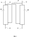
- FIG. 1 is a diagram representing the general operating principle of chemical loop combustion. It is in no way limiting to the CLC installation and process integrating the combustion reactor according to the invention.
- a reduced oxygen carrier 15 is brought into contact with an air flow 10 in a reaction zone 110 previously defined as the oxidation reactor (or air reactor). This results in a depleted air flow 11 and a flow of re-oxidized particles 14.
- the flow of oxidized oxygen carrier particles 14 is transferred into the reduction zone 100 previously defined as the combustion reactor (or combustion reactor). reduction).
- the flow of particles 14 is brought into contact with a fuel 12, which is a hydrocarbon feedstock. This results in a combustion effluent 13 and a flow of reduced oxygen carrier particles 15.
- the representation of the figure 1 does not understand the various equipment that can be part of the CLC unit, for solid/gas separation, solid/solid separation, heat exchange, pressurization, gas sealing between reactors (e.g. siphons), solid storage, control of solid flows (e.g. mechanical or pneumatic valves) or possible recirculation of material around the oxidation and combustion reactors.
- the hydrocarbon feedstock 12 is brought into cocurrent contact with the active redox mass in the form of particles to carry out the combustion of said feedstock by reduction of the active redox mass.
- the active redox mass M x O y M representing a metal, is reduced to the state M x O y-2n-m/2 , via the hydrocarbon charge C n H m , which is correlatively oxidized in CO 2 and H 2 O, according to reaction (1) below, or possibly in a CO + H 2 mixture depending on the proportions used.
- Total combustion of the hydrocarbon feedstock is generally targeted.
- the combustion of the charge in contact with the active mass is carried out at a temperature generally between 600°C and 1400°C, preferably between 800°C and 1000°C.
- the contact time varies depending on the type of fuel filler used. It typically varies between 1 second and 20 minutes, for example preferably between 1 minute and 10 minutes, and more preferably between 1 minute and 8 minutes for a solid or liquid load, and for example preferably from 1 to 20 seconds for a load gaseous.
- a mixture comprising the gases resulting from combustion and the particles of the active mass is evacuated to the top of the reduction zone 100.
- Gas/solid separation means (not shown), such as a cyclone, make it possible to separate the combustion gas 13 of the solid particles of the active mass in their most reduced state 15.
- a solid/solid separation device making it possible to separate the particles of The unburned particles of the active mass can be used at the outlet of the combustion reactor.
- This type of separator can be associated with one or more gas/solid separators arranged downstream of the solid/solid separator.
- the particles of the active mass having remained in the combustion reactor, and separated from the combustion gases, are sent to the oxidation zone 110 to be re-oxidized.
- the unburned products can be recycled to the reduction reactor 100.
- the active mass is restored to its oxidized state MxOy in contact with an oxidizing gas 10, typically air or water vapor, and preferably air, depending on the reaction (2) below, before returning to the reduction reactor 100, and after being separated from the oxygen-depleted gas 11, typically so-called “depleted” air, evacuated at the top of the oxidation reactor 110.
- an oxidizing gas 10 typically air or water vapor, and preferably air, depending on the reaction (2) below
- n and m respectively represent the number of carbon and hydrogen atoms having reacted with the active mass in the combustion reactor.
- the temperature in the oxidation reactor is generally between 600°C and 1400°C, preferably between 800 and 1000°C.
- the active mass passing alternately from its oxidized form to its reduced form and vice versa, describes an oxidation-reduction cycle.
- the treated hydrocarbon feedstocks can be solid or liquid hydrocarbon feedstocks.
- the solid loads can be chosen from coal, coke, petroleum coke (“pet-coke” in English), biomass, tar sands and household waste.
- Liquid fillers can be chosen from petroleum, bitumen, diesel, gasoline.
- the treated hydrocarbon filler is a solid filler, as stated above.
- the redox mass may be composed of metal oxides, such as for example oxides of Fe, Ti, Ni, Cu, Mn, Co, V, alone or in a mixture, which may come from ores (for example ilmenite or pyrolusite) or be synthetic (for example copper oxide particles supported on CuO/Al 2 O 3 alumina or nickel oxide particles supported on NiO/Al 2 O 4 alumina, preferably oxide particles of copper supported on alumina CuO/Al 2 O 3 ), with or without a binder, and has the required redox properties and the characteristics necessary for the implementation of fluidization.
- the oxygen storage capacity of the redox mass is advantageously, depending on the type of material, between 0.5% and 15% by weight.
- the quantity of oxygen actually transferred by the metal oxide is between 0.5% and 3% by weight, which allows only a fraction of the total oxygen transfer capacity to be used, ideally less than 30% of it in order to limit the risks of mechanical aging or particle agglomeration.
- Using only a fraction of the oxygen transport capacity also has the advantage that the fluidized bed acts as a thermal ballast and thus smooths out temperature variations along the path of the oxygen carrier.
- the active mass is in the form of fluidizable particles, belonging to groups A, B, C or D of the Geldart classification, alone or in combination.
- the particles of the redox active mass belong to group B of the Geldart classification.
- the group B particles used have a particle size such that more than 90% of the particles have a size between 100 ⁇ m and 500 ⁇ m, preferably between 150 ⁇ m and 300 ⁇ m.
- the particles of the oxidoreductive active mass which may be metallic oxides, synthetic or natural minerals, supported or not, have a density of between 1000 kg/m 3 and 5000 kg/m 3 and preferably between 1200 kg/m 3 m 3 and 4000 kg/m 3 .
- nickel oxide particles supported on alumina generally have a grain density of between 2500 and 3500 kg/m 3 depending on the porosity of the support and the oxide content. of nickel, typically around 3200 kg/m 3 .
- Ilmenite an ore combining titanium and iron (iron oxide and titanium), has a density of 4700 kg/m 3 .
- the active redox mass can undergo an activation phase so as to increase its reactive capacities, which may consist of a temperature rise phase, preferably progressive, and preferably under an oxidizing atmosphere (for example under air).
- the oxidation and combustion reactors operate in a fluidized bed. They each include at least one fluidization gas injection system.
- the fluidization gas may be CO 2 , which may be CO 2 produced during combustion and recycled, or water vapor.
- the fluidization gas is an oxidizing gas, preferably air.
- the oxidation reactor preferably comprises a transported fluidized bed.
- the speed of the gas is between 2 m/s and 15 m/s, and preferably between 3 m/s and 10 m/s.
- such a reactor can have a diameter of between 1 m and 6 m for a height of between 10 m and 30 m.
- the combustion reactor 100 is configured to include a dense bed and a transported bed arrangement.
- the combustion reactor 100 comprises a lower enclosure comprising a dense fluidized bed, surmounted by an upper enclosure comprising a transported fluidized bed.
- the upper enclosure has a smaller passage section than that of the lower enclosure, making it possible to accelerate and transport the gas-particle mixture leaving the lower enclosure.
- the speed of the gas in the lower enclosure is between 0.3 m/s and 3 m/s.
- the speed of the gas in the upper enclosure of the combustion reactor is between 3 m/s and 15m/s.
- the combustion reactor 100 can have a diameter of between 1 and 10 m, for a height of between 3 m and 40 m.
- the section ratio between the lower enclosure and the upper enclosure is between 2 and 15, preferably from 3 to 10.
- dense fluidized bed we mean a bubbling bed or a turbulent bed.
- the volume fraction of solid in such a dense fluidized bed is generally between 0.25 and 0.50.
- diluted fluidized bed we mean a transported bed.
- the solid volume fraction is generally less than 0.25.
- the geometry of the reactors can be parallelepiped, cylindrical or any other three-dimensional geometry preferably comprising a symmetry of revolution.
- cylindrical we refer to a cylinder of revolution.
- the combustion reactor in particular the lower and upper enclosures, has a parallelepiped shape, preferably rectangular.
- the lower and upper enclosures of the combustion reactor have such a shape.
- This form of reactor is well suited to industrial implementation of CLC involving large equipment.
- large size we mean reactors so the passage section is expressed in tens of m 2 , over heights of several tens of meters.
- this particular geometry also has the advantage of simplifying the possible installation of refractory materials on the internal face in order to protect against strong temperatures the generally metallic wall of the reactor enclosure.
- Such refractory materials can be used in combination with standard steels in order to limit manufacturing costs.
- layers of reinforced refractory cement typically having thicknesses generally between 2 and 50 cm, generally close to 20 cm, on the internal faces exposed to flow and high temperatures make it possible to use standard steels for the external parts of the reactor.
- Bricks can also be used as refractory material on the internal faces of the walls of the reactor enclosure.
- the materials used to make the reactors and its constituent elements can be chosen from refractory materials, for example of the refractory concrete, refractory brick or ceramic type, high temperature steels, for example of the Hastelloy ® , Incoloy ® , Inconel ® or Manaurite ® type, or conventional steels, for example of the stainless steel or carbon steel type combined with refractory materials or combined with cooling means such as tubes in which a heat transfer fluid circulates.
- the lower enclosure comprises a dense fluidized bed and the upper enclosure comprises a transported fluidized bed.
- a geometry is well suited to the combustion of solid or liquid loads, in particular solids, which require a sufficiently long contact time with the particles of the active mass to tend towards total combustion, and which involve a first phase of gasification of the solid or liquid charge (in a dense fluidized bed), followed by combustion of the gasified charge (in a dense fluidized bed and in a transported fluidized bed).
- the gasification of the charge contributes to increasing the speed of the gas in the lower enclosure with a substantially constant passage section. This increase in gas speed is also achieved due to the narrower passage section in the upper enclosure.
- the size of the bubbles can become very large, until approaching the size of the passage section of the lower enclosure, characterizing the pistoning phenomenon during the speed of the lower enclosure.
- pistoning transient between the bubbling bed regime and the turbulent regime and pose the problems of pressure fluctuation, vibration, temperature heterogeneity and solid/gas mixture as already described, and harmful to the integrity of the installation CLC and the performance of the CLC process.
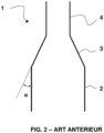
- a known combustion reactor 1 is illustrated schematically in figure 2 .
- Such a combustion reactor is for example described in the application WO11151535 . It comprises a lower enclosure 2 comprising a dense bed and an upper enclosure 4 comprising a diluted bed.
- the upper enclosure 4 has an elongated shape and a passage section strictly smaller than that of the lower enclosure, for example less by at least 25% than that of the lower enclosure, or even by at least 50%.
- This upper enclosure 4 is a “riser”.
- the change in section makes it possible to increase the speed between the lower enclosure 2 and the upper enclosure 4 and to ensure the transition between dense phase flow and dilute phase flow.
- the lower enclosure 2 comprises a supply conduit for the hydrocarbon feed, a particle supply conduit for the active mass coming from the oxidation reactor, a system for injecting a fluidization gas positioned at the base of enclosure 2, at a level lower than that of the supply conduits for the hydrocarbon feed and the particles of the active mass, and allowing the formation of the dense bed.
- a fluidization gas is introduced by specific means which may be perforated plates arranged downstream of a distributor which may be a wind box supplied by a conduit for supplying said gas. These plates can be inclined at an angle generally between 30° and 70° relative to the horizontal and can leave in the central part a free space for the flow of particles, making it possible to draw off part of the particles through the distributor. particles sedimenting in this zone and consisting mainly of agglomerated ashes.
- the lower enclosure 2 may also include one or more pipes for recycling unburned particles connected to solid/solid separation systems (elutriation separation devices) and/or gas/solid (e.g. cyclones).
- solid/solid separation systems elutriation separation devices
- gas/solid e.g. cyclones
- the upper enclosure 4 has at its top an evacuation for the gas mixture comprising the combustion gases and the particles of the active mass, and possibly unburnt particles and ashes.
- the upper enclosure 4 can also include a supply of active mass particles.
- the combustion of the gaseous effluent from the lower enclosure 2 can be carried out.
- This gaseous effluent includes the gasified solid charge, partially converted, or even completely converted.
- the average residence time of the gas in this upper enclosure 4 is generally between 1 second and 20 seconds, the average residence time of the solids varying between 2 seconds and 1 minute. Under these conditions, and taking into account the dilute nature of the flow and the presence of particles of the active mass of oxygen, the reactions are essentially reactions between the gas phase (gasified charge) and the particles of the active mass .
- a conduit of variable section 3 makes it possible to make the junction between the lower enclosure 2 and the upper enclosure 4, and allows the evacuation of gaseous effluents and particles entrained towards the upper enclosure 4.
- this conduit is a cone 3.
- the wall of cone 3 forms a non-zero angle ⁇ with the walls of the lower and upper enclosures, i.e. with the vertical.
- the bubbles carrying the agglomerates of solids slide on the conical wall 3, concentrate at the entrance to the upper enclosure 4, and then cause, when they burst, strong pressure fluctuations.
- agglomerates of solids we mean particles which have slightly agglomerated together to form larger clusters. These clusters can be carried away by the bubbles.
- the entrainment of agglomerates in the upper enclosure 4 creates a flow which is not uniform, also causing pressure fluctuations in the upper enclosure 4.
- the entrainment of agglomerates of solid particles in the enclosure upper 4 is harmful because these can in turn cause pistoning phenomena in the upper enclosure 4, a phenomenon all the more likely to occur as the section is reduced.
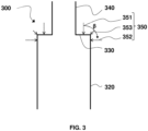
- This intermediate part constitutes a sort of flat ceiling for the lower enclosure 320.
- internal wall of the intermediate part 330 is meant the face of the wall forming this intermediate part 330 located inside the enclosure 320, in contact with the fluidized bed.
- the intermediate part 330 comprises an external wall, ie a face of the wall forming this intermediate part 330 located outside the enclosure 320, which is slightly curved to facilitate the anchoring of a material refractory.
- the curvature can be of elliptical shape, and have a ratio of the semi-axes (ratio between the major axis and the minor axis) preferably between 2 and 30, and more preferably between 5 and 20.
- the shape of the external wall can be of different shape, such as those described in the normative document NFE81-100 specific to rounded bottoms. Examples of refractory materials have been given above in relation to the description of the installation and the CLC process illustrated in figure 1 .
- a flat roof is well preserved for the lower enclosure inside the reactor, that is to say a right angle for the junction inside the reactor (internal wall of the intermediate part 330 ) between the side wall of the lower enclosure 320 and the side wall of the upper enclosure 340.
- the combustion reactor according to the invention may comprise other elements similar to those described above for the combustion reactor 1 according to the prior art, not shown on the Figure 3 .
- the lower enclosure 320 may also include one or more recycling lines for unburned particles connected to solid/solid separation systems (elutriation separation devices) and/or gas/solid (e.g. cyclones).
- solid/solid separation systems elutriation separation devices
- gas/solid e.g. cyclones
- the upper enclosure 340 advantageously includes an evacuation at its top for the gas mixture comprising the combustion gases and the particles of the active mass, and possibly particles of unburned matter and ashes.
- the upper enclosure 340 may also include a supply of active mass particles.
- the upper enclosure 340 may have a passage section lower than the passage section of the lower enclosure 320 by at least 25%, or even lower by at least 50%.
- the passage from the section of the lower enclosure 320 to the reduced section of the upper enclosure 340 makes it possible to increase the speed of the flow between the two enclosures and to ensure the transition between the flow in dense phase and the dilute phase flow.
- the combustion of the gaseous effluent from the lower enclosure 320 can be carried out.
- This gaseous effluent includes the gasified solid charge, partially converted, or even completely converted.
- the average residence time of the gas in this upper enclosure is generally between 1 second and 20 seconds, the average residence time of the solids varying between 2 seconds and 1 minute. Under these conditions, and taking into account the dilute nature of the flow and the presence of particles of the active mass of oxygen, the reactions are essentially reactions between the gas phase (gasified charge) and the particles of the active mass .
- the upper enclosure comprises a diluted fluidized bed having a solid volume fraction of less than 0.10.
- the lower enclosure 320 further comprises a secondary injection system 350 for a secondary fluidization gas positioned at the top of the lower enclosure 320.
- the secondary fluidization gas can be injected at the top of the lower enclosure 320 of the combustion reactor 300, and preferably form at least one jet in the enclosure in a direction forming an angle ⁇ of between 0 and 90 ° (values included) with the vertical.
- the secondary fluidization gas can be injected at the top of the lower enclosure 320 of the combustion reactor 300, and preferably form at least one jet in the enclosure in a direction forming an angle ⁇ of between 0 and 90 ° (values included) with the vertical.
- the flow rate of the secondary fluidization gas is less than 0.2 ⁇ Q GP , Q GP being the flow rate of the main fluidization gas.
- the flow rate of the secondary fluidization gas is between 0.02 ⁇ Q GP and 0.2 ⁇ Q GP , and more preferably between 0.05 ⁇ Q GP and 0.15 ⁇ Q GP .
- the lower enclosure further comprises a tertiary injection system (not shown) for a tertiary fluidization gas positioned between the main injection system and the top of the lower enclosure, configured to control the level of the dense bed
- a tertiary fluidization gas is thus injected into a zone of the dense bed in the lower enclosure of the combustion reactor so as to control the level of the dense bed, by affecting the entrainment of the solid particles.
- the disengagement zone is the diluted zone above the dense bed (between the interface of the dense bed and the top of the enclosure).
- this injection can be done so as to form at least one jet in the enclosure in a direction forming an angle between 90°, value included (horizontal direction), and 180°, value excluded, with the vertical. Jets in several of these directions can also be made.
- the main fluidization gas can be CO 2 , for example CO 2 produced during combustion and recycled, or water vapor.
- the other fluidization gases, secondary and tertiary, may be of the same nature as the main fluidization gas and come from the same source.
- a combustion reactor 400 according to a second embodiment of the invention is illustrated in the figure 4 , and is in every respect identical to the reactor 300 described above in relation to the Figure 3 , with the exception of the upper enclosure 440, which comprises a segment 441 penetrating into the lower part of the enclosure with a height h preferably between 0.01xH and 0.3xH, H being the height of the lower enclosure 320 of the combustion reactor.
- the height H of the lower enclosure 320 can be between 3 m and 40 m, for example be 20 m.
- the height of the upper enclosure 440 can be between 3 m and 40 m, for example be 20 m.
- the ratio of passage section of the lower enclosure to passage section of the upper enclosure can be between 2 and 15, and preferably between 3 and 10.
- the present invention also relates to the CLC installation comprising the combustion reactor according to the invention as described above, operating in a fluidized bed to carry out the combustion of said hydrocarbon feed in contact with the particles of the active mass of oxido- reduction, and comprising the oxidation reactor operating in a fluidized bed to oxidize the particles of the reduced redox active mass coming from the combustion reactor by contacting with an oxidizing gas. Details of such an installation have already been given in relation to the figure 1 .
- the gaseous effluent from the lower enclosure includes the gasified solid charge as well as the effluents from the combustion carried out in the lower enclosure.
- the upper enclosure of the combustion reactor also receives the particles of the active mass from the part lower, as well as possibly unburned particles and possibly fly ash, particularly in the case of combustion of solid loads.
- unburned particles we mean the particles of the solid hydrocarbon feed which have not undergone total combustion, and which therefore still contain hydrocarbon compounds.
- Ashes are incombustible elements resulting from the total combustion of solid fuel particles and for which the residence time in the combustion reactor has been sufficient.
- the ashes are essentially mineral in nature.
- They typically contain the following compounds: SiO 2 , Al 2 O 3 , Fe 2 O 3 , CaO, MgO, TiO 2 , K 2 O, Na 2 O, SO 3 , P 2 O 5 . They are characterized by a particle size and density lower than active mass particles (ie less than 100 ⁇ m) and often also lower than unburned particles.
- the particles of the redox active mass having remained in the combustion reactor are separated from the combustion gases by means of at least one solid/solid separator and /or solid/gas.
- Such separators are for example described in patent applications WO11151535 And WO11151537 .
- solid/solid separator we mean a device allowing the separation between two populations of solid particles: the particles of the oxygen carrier and the particles of unburned particles which leave the combustion reactor.
Landscapes
- Engineering & Computer Science (AREA)
- Chemical & Material Sciences (AREA)
- Combustion & Propulsion (AREA)
- Mechanical Engineering (AREA)
- General Engineering & Computer Science (AREA)
- Devices And Processes Conducted In The Presence Of Fluids And Solid Particles (AREA)
- Fluidized-Bed Combustion And Resonant Combustion (AREA)
Description
La présente invention concerne le domaine de la combustion de charges hydrocarbonées par oxydo-réduction en boucle chimique (CLC) opérant en lit fluidisé, et plus spécifiquement concerne un réacteur de combustion CLC opérant en lit fluidisé particulièrement bien adapté à la combustion de charges hydrocarbonées solides ou liquides.The present invention relates to the field of combustion of hydrocarbon feedstocks by chemical loop redox (CLC) operating in a fluidized bed, and more specifically relates to a CLC combustion reactor operating in a fluidized bed particularly well suited to the combustion of solid hydrocarbon feedstocks. or liquids.
La combustion en boucle chimique, ou procédé de Chemical Looping Combustion (CLC) dans sa terminologie anglo-saxonne, est un procédé consistant à mettre en oeuvre des réactions d'oxydo-réduction d'une masse active, typiquement un oxyde métallique, pour décomposer la réaction de combustion d'une charge hydrocarbonée en deux réactions successives : une première réaction d'oxydation de la masse active au contact d'un gaz oxydant, typiquement de l'air, dans au moins une zone d'oxydation, et une deuxième réaction de réduction de la masse active au contact de la charge dont on souhaite la combustion dans au moins une zone de combustion.Chemical loop combustion, or Chemical Looping Combustion (CLC) process in its Anglo-Saxon terminology, is a process consisting of implementing redox reactions of an active mass, typically a metal oxide, to decompose the combustion reaction of a hydrocarbon feedstock in two successive reactions: a first oxidation reaction of the active mass in contact with an oxidizing gas, typically air, in at least one oxidation zone, and a second reaction of reduction of the active mass in contact with the charge whose combustion is desired in at least one combustion zone.
La masse active oxydo-réductrice, qui cède une partie de l'oxygène qu'elle renferme au contact avec la charge dans la zone de combustion, joue ainsi un rôle de transporteur d'oxygène entre ladite zone de combustion et la zone d'oxydation où elle est à nouveau oxydée.The active redox mass, which releases part of the oxygen it contains upon contact with the charge in the combustion zone, thus plays the role of oxygen transporter between said combustion zone and the oxidation zone. where it is oxidized again.
Ce matériau solide se présente sous la forme de particules fluidisables, appartenant aux groupes A, B ou C de la classification de Geldart qui est basée sur la taille des particules et sur leur écart de masse volumique avec le gaz, et souvent au groupe B. Les particules sont mises en contact dans les zones réactionnelles, avec soit le gaz oxydant soit la charge, sous forme de lits fluidisés, et sont généralement transportées d'une zone à l'autre sous une forme fluidisée. L'ensemble des particules transportées sous une forme fluidisée est communément appelé lit fluidisé circulant ou transporté.This solid material is in the form of fluidizable particles, belonging to groups A, B or C of the Geldart classification which is based on the size of the particles and their density difference with the gas, and often to group B. The particles are brought into contact in the reaction zones, with either the oxidizing gas or the feed, in the form of fluidized beds, and are generally transported from one zone to another in a fluidized form. The set of particles transported in a fluidized form is commonly called a circulating or transported fluidized bed.
Ces particules sont oxydées au contact d'un gaz oxydant, typiquement de l'air (ou de la vapeur d'eau), dans au moins une première zone réactionnelle, appelée réacteur d'oxydation ou réacteur air. Elles sont ensuite transportées dans au moins une seconde zone réactionnelle appelée réacteur de réduction ou réacteur de combustion ou encore réacteur fuel, où elles sont mises en contact avec une charge hydrocarbonée solide (ex : charbon, le coke, le coke de pétrole appelé « pet-coke » en anglais, la biomasse, les sables bitumineux, les déchets ménagers), liquide (ex. : fuel, bitume, diesel, essences, huile de schiste, etc.) ou gazeuse (ex. : gaz naturel, syngas, biogaz, gaz de schiste) dont on souhaite effectuer la combustion. L'oxygène transporté par les particules de la masse active alimente la combustion de la charge. Il en résulte un effluent gazeux formé par la combustion de la charge et un flux de particules réduites. Les particules sont renvoyées au réacteur air pour y être ré-oxydées, fermant ainsi la boucle.These particles are oxidized on contact with an oxidizing gas, typically air (or water vapor), in at least a first reaction zone, called an oxidation reactor or air reactor. They are then transported to at least a second reaction zone called a reduction reactor or combustion reactor or fuel reactor, where they are brought into contact with a solid hydrocarbon feedstock (e.g. coal, coke, petroleum coke called “pet-coke” in English, biomass, tar sands, household waste), liquid (e.g. fuel oil, bitumen, diesel, gasoline, shale oil, etc.) or gaseous ( e.g.: natural gas, syngas, biogas, shale gas) which we wish to combust. The oxygen transported by the particles of the active mass fuels the combustion of the charge. This results in a gaseous effluent formed by the combustion of the charge and a flow of reduced particles. The particles are returned to the air reactor to be re-oxidized, thus closing the loop.
Le procédé CLC permet de produire de l'énergie (vapeur, électricité...) par récupération de la chaleur dégagée par les réactions de combustion tout en facilitant la capture du dioxyde de carbone (CO2) émis lors de la combustion grâce à la production de fumées riches en CO2. Le captage du CO2 peut en effet se faire après condensation de la vapeur d'eau et compression des fumées, et celui-ci peut alors être stocké, par exemple dans un aquifère profond, ou être valorisé, par exemple en l'employant pour améliorer le rendement des exploitations pétrolières dans des procédés de récupération assistée du pétrole (EOR pour Enhanced Oil Recovery en anglais) ou de gaz (EGR pour Enhanced Gas Recovery en anglais).The CLC process makes it possible to produce energy (steam, electricity, etc.) by recovering the heat released by combustion reactions while facilitating the capture of carbon dioxide (CO 2 ) emitted during combustion thanks to the production of smoke rich in CO 2 . The capture of CO 2 can in fact be done after condensation of the water vapor and compression of the fumes, and it can then be stored, for example in a deep aquifer, or be valorized, for example by using it for improve the performance of oil operations in enhanced oil recovery (EOR) or gas recovery (EGR) processes.
Le procédé CLC peut également permettre la production de gaz de synthèse, voire d'hydrogène, en contrôlant la combustion et en mettant en oeuvre les purifications requises en aval du procédé de combustion.The CLC process can also allow the production of synthesis gas, or even hydrogen, by controlling combustion and implementing the purifications required downstream of the combustion process.
Un autre avantage résulte de ce mode de combustion : la production d'un flux très riche en azote, qui est l'air appauvri obtenu à l'issue de l'oxydation de la masse active dans le réacteur air. Selon le degré de pureté atteint, ce flux d'azote peut être valorisé dans diverses applications, notamment dans le domaine de l'industrie pétrolière. Il peut par exemple être utilisé en raffinerie en tant que gaz inerte dans différents procédés de raffinage du pétrole ou pour le traitement des eaux de production, ou en tant que gaz injecté dans le sous-sol dans des procédés EOR.Another advantage results from this mode of combustion: the production of a flow very rich in nitrogen, which is the depleted air obtained following the oxidation of the active mass in the air reactor. Depending on the degree of purity achieved, this nitrogen flow can be used in various applications, particularly in the oil industry. It can for example be used in refineries as an inert gas in various oil refining processes or for the treatment of produced water, or as a gas injected into the subsoil in EOR processes.
Différents régimes de fluidisation peuvent être mis en oeuvre dans les différentes unités de l'installation CLC, en particulier dans les réacteurs d'oxydation et de réduction opérant en lit fluidisé. Le régime de fluidisation appliqué dépend en effet de l'opération à réaliser (combustion de la charge, oxydation des particules du porteur d'oxygène, transport des particules, séparation solide/solide, séparation solide/gaz) et du type de charge traitée.Different fluidization regimes can be implemented in the different units of the CLC installation, in particular in the oxidation and reduction reactors operating in a fluidized bed. The fluidization regime applied depends in fact on the operation to be carried out (combustion of the charge, oxidation of the particles of the oxygen carrier, transport of the particles, solid/solid separation, solid/gas separation) and the type of charge treated.
Par exemple, la combustion d'une charge solide elle-même sous forme de particules, nécessite un temps de contact avec les particules du porteur d'oxygène plus grand que la combustion d'une charge gazeuse, ce qui se traduit généralement par la mise en oeuvre dans le réacteur de combustion d'une zone comportant un lit fluidisé dense, opérant selon un régime de fluidisation hétérogène correspondant à un lit dit bouillonnant (présence de bulles dans le lit) ou turbulent (régime d'écoulement préféré), dans lequel les particules du porteur d'oxygène et de la charge solide sont mises en contact pour une première étape de combustion consistant essentiellement à une gazéification de la charge solide. Une deuxième étape est généralement nécessaire pour tendre vers une combustion totale, avec la mise en contact des particules du porteur d'oxygène et la charge gazéifiée. Cette deuxième étape est généralement réalisée dans la première zone réactionnelle, et peut aussi être réalisée dans une deuxième zone réactionnelle comportant un lit fluidisé dilué, opérant selon un régime de fluidisation transporté (correspondant au régime des lits fluidisés circulants) impliquant des vitesses de gaz plus importantes. Cette zone réactionnelle correspond généralement à une partie du réacteur formant un conduit sensiblement allongé et vertical communément appelé « riser », terme issu de la terminologie anglo-saxonne et communément utilisé par l'homme du métier. Une telle configuration impliquant une première zone de combustion en lit fluidisé dense surmontée par une deuxième zone de combustion de type riser opérant en lit fluidisé dense est par exemple décrite dans la demande de brevet
Dans le cas de la combustion en boucle chimique de charges gazeuses, le temps de contact nécessaire entre les particules de la masse active et la charge étant moins important que dans le cas de charges solides ou liquides, un réacteur de type riser peut suffire pour réaliser la combustion de la charge.In the case of chemical loop combustion of gaseous charges, the contact time necessary between the particles of the active mass and the charge being less important than in the case of solid or liquid charges, a riser type reactor may be sufficient to achieve combustion of the charge.
De manière générale, l'augmentation de la vitesse de gaz dans un lit fluidisé génère différents régimes d'écoulement. Selon le groupe de la classification de Geldart auquel appartiennent les particules de solide, différents régimes de fluidisation sont possibles lorsque la vitesse du gaz croît.Generally speaking, increasing the gas velocity in a fluidized bed generates different flow regimes. Depending on the group in the Geldart classification to which the solid particles belong, different fluidization regimes are possible when the gas velocity increases.
Avec des particules du groupe B de la classification de Geldart par exemple, en augmentant progressivement le débit de gaz, l'écoulement passe du régime à bulles (lit bouillonnant qui est un lit dense), au régime de pistonnage, dit 'slugging' en anglais (suivant les hauteur et diamètre de lit), au régime turbulent, au régime de fluidisation rapide (lit circulant) puis au régime de transport. Bien qu'à faible vitesse du gaz le régime de fluidisation peut différer selon le groupe des particules, elles atteignent toutes, quel que soit leur groupe, un régime de fluidisation turbulent, puis un régime de fluidisation rapide, suivi d'un régime de transport lorsque la vitesse du gaz croît.With particles from group B of the Geldart classification for example, by gradually increasing the gas flow rate, the flow goes from the bubble regime (bubbling bed which is a dense bed), to the spooling regime, known as 'slugging' in English (depending on the height and diameter of the bed), at the turbulent regime, at the rapid fluidization regime (circulating bed) then at the transport regime. Although at low gas speed the fluidization regime may differ depending on the group of particles, they all reach, whatever their group, a turbulent fluidization regime, then a rapid fluidization regime, followed by a transport regime when the speed of the gas increases.
Le régime de pistonnage apparait lorsque le diamètre des bulles devient comparable au diamètre de la colonne : avec des particules du groupe B, les bulles grossissent en s'élevant dans le réacteur, leur taille pouvant atteindre à l'extrême le diamètre du réacteur. Dans ce cas, le régime atteint est celui du pistonnage, générant des écoulements en 'bouchons'. Les grosses bulles éclatent à la surface du lit ou en paroi, avec des agglomérats denses de solide entrainés dans leur sillage, générant de fortes hétérogénéités d'écoulement, et se traduisant par de fortes fluctuations de pression et des vibrations.The pistoning regime appears when the diameter of the bubbles becomes comparable to the diameter of the column: with group B particles, the bubbles grow in size as they rise in the reactor, their size being able to reach the diameter of the reactor in the extreme. In this case, the regime reached is that of pistoning, generating 'plug' flows. Large bubbles burst on the surface of the bed or on the wall, with dense agglomerates of solid carried in their wake, generating strong flow heterogeneities, and resulting in strong pressure fluctuations and vibrations.
Le régime turbulent est quant à lui particulièrement intéressant pour les procédés industriels car il présente un mélange beaucoup plus homogène des phases et un transfert de masse et thermique très important, par rapport aux régimes bouillonnant et de pistonnage. C'est un régime qui correspond à une forte agitation des particules : au fur et à mesure que la vitesse de fluidisation augmente, la taille et le nombre des bulles croissent progressivement et l'agitation de la suspension devient de plus en plus violente. Cette agitation est produite par l'ascension des bulles et par le fait qu'elles entraînent dans leur sillage une partie de la suspension. À des vitesses importantes, la forme des bulles devient irrégulière. Néanmoins, même si les grosses bulles formées n'atteignent pas le diamètre du réacteur, celles-ci peuvent engendrer de grosses fluctuations de pression et des vibrations au sein du lit, typiquement lors de leurs brisures au sein du lit, en surface du lit et en parois du réacteur.The turbulent regime is particularly interesting for industrial processes because it presents a much more homogeneous mixture of phases and a very significant mass and thermal transfer, compared to the bubbling and pistoning regimes. It is a regime which corresponds to strong agitation of the particles: as the fluidization speed increases, the size and number of bubbles gradually increase and the agitation of the suspension becomes more and more violent. This agitation is produced by the rise of the bubbles and by the fact that they carry part of the suspension in their wake. At high speeds, the shape of the bubbles becomes irregular. However, even if the large bubbles formed do not reach the diameter of the reactor, they can cause large pressure fluctuations and vibrations within the bed, typically when they break within the bed, on the surface of the bed and in the walls of the reactor.
Le régime de pistonnage ainsi que la formation de grosses bulles sont donc indésirables pour plusieurs raisons : le mélange du solide et gaz est moins bon (moins homogène), l'homogénéité de la température du réacteur n'est plus assurée, et les fortes fluctuations de pression et vibrations sur les parois et le fond du réacteur sont nuisibles à la tenue mécanique du réacteur.The pistoning regime as well as the formation of large bubbles are therefore undesirable for several reasons: the mixture of solid and gas is less good (less homogeneous), the homogeneity of the reactor temperature is no longer ensured, and the strong fluctuations pressure and vibrations on the walls and bottom of the reactor are harmful to the mechanical strength of the reactor.
Dans le cas d'un réacteur en lit fluidisé connecté par sa partie supérieure à un conduit allongé de diamètre plus faible (« riser »), tel que le réacteur CLC mentionné plus haut et décrit dans la demande
Il est connu des dispositifs pour diminuer le phénomène de pistonnage. Par exemple le brevet
La présente invention propose de fournir une autre solution dédiée au CLC pour diminuer les problèmes liés au phénomène de pistonnage, en particulier limiter les fortes fluctuations de pression dans le réacteur de combustion et notamment dans la partie allongée du réacteur (« riser »).The present invention proposes to provide another solution dedicated to CLC to reduce the problems linked to the pistoning phenomenon, in particular to limit the strong pressure fluctuations in the combustion reactor and in particular in the elongated part of the reactor ("riser").
La présente invention a pour objectif de fournir un réacteur de combustion CLC permettant de limiter les effets indésirables engendrés par la mise en oeuvre de régimes de fluidisation de pistonnage et de turbulence dans le réacteur, en particulier de limiter les fortes fluctuations de pression provoquées par la formation de grosses bulles et leur éclatement. Elle vise ainsi à préserver la tenue mécanique du réacteur de combustion, à assurer une homogénéité de température dans le réacteur, ainsi qu'à assurer une homogénéité du mélange gaz/particules dans le réacteur en vue d'une combustion optimale.The present invention aims to provide a CLC combustion reactor making it possible to limit the undesirable effects generated by the implementation of pistoning and turbulence fluidization regimes in the reactor, in particular to limit the strong pressure fluctuations caused by the formation of large bubbles and their bursting. It thus aims to preserve the mechanical strength of the combustion reactor, to ensure temperature homogeneity in the reactor, as well as to ensure homogeneity of the gas/particle mixture in the reactor with a view to optimal combustion.
Ainsi, pour atteindre au moins l'un des objectifs susvisés, parmi d'autres, la présente invention propose, selon un premier aspect, un réacteur de combustion pour la combustion en boucle chimique configuré pour opérer en lit fluidisé comportant :
- une enceinte inférieure formant une première zone réactionnelle pour la combustion d'une charge hydrocarbonée en présence de particules d'une masse active d'oxydo-réduction, ladite enceinte inférieure comportant une première paroi latérale et étant configurée pour comporter un lit fluidisé dense ;
- une enceinte supérieure de forme allongée et ayant une section de passage plus petite que la section de passage de ladite enceinte inférieure, formant une deuxième zone réactionnelle pour la combustion des effluents gazeux issus de la combustion dans ladite partie inférieure, ladite enceinte supérieure comportant une deuxième paroi latérale et étant configurée pour comporter un lit fluidisé dilué ;
- une partie intermédiaire connectant ladite enceinte inférieure à ladite enceinte supérieure, ladite partie intermédiaire comportant une paroi interne formant un angle droit avec la première paroi latérale de l'enceinte inférieure et avec la deuxième paroi latérale de l'enceinte supérieure.
- a lower enclosure forming a first reaction zone for the combustion of a hydrocarbon feedstock in the presence of particles of an active redox mass, said lower enclosure comprising a first side wall and being configured to comprise a dense fluidized bed;
- an upper enclosure of elongated shape and having a passage section smaller than the passage section of said lower enclosure, forming a second reaction zone for the combustion of gaseous effluents resulting from combustion in said lower part, said upper enclosure comprising a second side wall and being configured to include a diluted fluidized bed;
- an intermediate part connecting said lower enclosure to said upper enclosure, said intermediate part comprising an internal wall forming a right angle with the first side wall of the lower enclosure and with the second side wall of the upper enclosure.
Selon un mode de réalisation, l'enceinte inférieure comporte un système d'injection principal pour un gaz de fluidisation principal positionné à la base de l'enceinte inférieure.According to one embodiment, the lower enclosure comprises a main injection system for a main fluidization gas positioned at the base of the lower enclosure.
Selon un mode de réalisation, l'enceinte inférieure comporte en outre un système d'injection secondaire pour un gaz de fluidisation secondaire positionné au sommet de l'enceinte inférieure.According to one embodiment, the lower enclosure further comprises a secondary injection system for a secondary fluidization gas positioned at the top of the lower enclosure.
Selon un mode de réalisation, l'enceinte inférieure comporte en outre un système d'injection tertiaire pour un gaz de fluidisation tertiaire positionné entre le système d'injection principal et le sommet de l'enceinte inférieure, configuré pour contrôler le niveau du lit dense.According to one embodiment, the lower enclosure further comprises a tertiary injection system for a tertiary fluidization gas positioned between the main injection system and the top of the lower enclosure, configured to control the level of the dense bed .
Selon un mode de réalisation, la partie supérieure du réacteur de combustion comporte un segment pénétrant dans la partie inférieure de l'enceinte d'une hauteur h de préférence comprise entre 0,01xH et 0,3xH, H étant la hauteur de l'enceinte inférieure du réacteur de combustion.According to one embodiment, the upper part of the combustion reactor comprises a segment penetrating into the lower part of the enclosure with a height h preferably between 0.01xH and 0.3xH, H being the height of the enclosure lower part of the combustion reactor.
Selon un mode de réalisation, le ratio de la section de passage de l'enceinte inférieure sur la section de passage de l'enceinte supérieure est compris entre 2 et 15, et de préférence entre 3 et 10.According to one embodiment, the ratio of the passage section of the lower enclosure to the passage section of the upper enclosure is between 2 and 15, and preferably between 3 and 10.
Selon un mode de réalisation, les enceintes inférieure et supérieure du réacteur ont une forme de parallélépipède, de préférence rectangle.According to one embodiment, the lower and upper enclosures of the reactor have a parallelepiped shape, preferably rectangular.
Selon un deuxième aspect, la présente invention propose un procédé de combustion en boucle chimique d'une charge hydrocarbonée mettant en oeuvre un réacteur de combustion selon l'invention ou l'installation selon l'invention, comportant les étapes suivantes :
- on met en contact des particules d'une masse active oxydo-réductrice avec la charge hydrocarbonée dans l'enceinte inférieure du réacteur de combustion au sein d'un lit fluidisé dense formé par l'injection d'un gaz de fluidisation principal ;
- on effectue une combustion des effluents gazeux issus l'enceinte inférieure en présence de particules de la masse active oxydo-réductrice dans l'enceinte supérieure du réacteur de combustion, au sein d'un lit fluidisé dilué ;
- on effectue une oxydation des particules de la masse active oxydo-réductrice ayant séjourné dans le réacteur de combustion au sein d'un réacteur d'oxydation opérant en lit fluidisé avant de les renvoyer vers le réacteur de combustion.
- particles of an active redox mass are brought into contact with the hydrocarbon feedstock in the lower enclosure of the combustion reactor within a dense fluidized bed formed by the injection of a main fluidization gas;
- combustion of the gaseous effluents from the lower enclosure is carried out in the presence of particles of the active redox mass in the upper enclosure of the combustion reactor, within a diluted fluidized bed;
- the particles of the active redox mass having remained in the combustion reactor are oxidized within an oxidation reactor operating in a fluidized bed before returning them to the combustion reactor.
Selon un mode de réalisation, la charge hydrocarbonée est une charge solide, de préférence choisie parmi le charbon, le coke, le coke de pétrole, la biomasse, les sables bitumineux et les déchets ménagers et on effectue une séparation de particules d'imbrûlés et des particules de la masse active oxydo-réductrice contenues dans un mélange gazeux comportant des gaz de combustion issu de l'enceinte supérieure du réacteur de combustion dans un séparateur de particules solide/solide, on envoie les particules de la masse active oxydo-réductrice ainsi séparées vers le réacteur d'oxydation, et on recycle les particules d'imbrûlés, éventuellement séparées des gaz de combustion dans au moins un étage de séparation gaz-solide, dans le réacteur de combustion.According to one embodiment, the hydrocarbon feedstock is a solid feedstock, preferably chosen from coal, coke, petroleum coke, biomass, bituminous sands and household waste and a separation of unburnt particles is carried out and particles of the redox active mass contained in a gas mixture comprising combustion gases coming from the upper enclosure of the combustion reactor into a solid/solid particle separator, the particles of the redox active mass are sent thus separated towards the oxidation reactor, and the unburnt particles, optionally separated from the combustion gases in at least one gas-solid separation stage, are recycled into the combustion reactor.
Selon un mode de réalisation, la vitesse superficielle du gaz dans l'enceinte inférieure du réacteur de combustion est comprise entre 0,3 m/s et 3 m/s, et dans lequel la vitesse superficielle du gaz dans l'enceinte supérieure du réacteur de combustion est comprise entre 3 m/s et 15 m/s.According to one embodiment, the superficial speed of the gas in the lower enclosure of the combustion reactor is between 0.3 m/s and 3 m/s, and in which the superficial speed of the gas in the upper enclosure of the reactor combustion is between 3 m/s and 15 m/s.
Selon un mode de réalisation, la température dans le réacteur de combustion est comprise entre 600°C et 1400°C, de préférence entre 800°C et 1000°C.According to one embodiment, the temperature in the combustion reactor is between 600°C and 1400°C, preferably between 800°C and 1000°C.
Selon un mode de réalisation, on injecte un gaz de fluidisation secondaire au sommet de l'enceinte inférieure du réacteur de combustion, de préférence formant un jet selon une direction formant un angle β compris entre 0 et 90° avec la verticale.According to one embodiment, a secondary fluidization gas is injected at the top of the lower enclosure of the combustion reactor, preferably forming a jet in a direction forming an angle β of between 0 and 90° with the vertical.
De préférence, le débit du gaz de fluidisation secondaire est compris entre 0,02×QGP et 0,2×QGP, QGP étant le débit du gaz de fluidisation principal.Preferably, the flow rate of the secondary fluidization gas is between 0.02×Q GP and 0.2×Q GP , Q GP being the flow rate of the main fluidization gas.
Selon un mode de réalisation, on injecte un gaz de fluidisation tertiaire dans une zone du lit dense dans l'enceinte inférieure du réacteur de combustion de manière à contrôler le niveau du lit dense.According to one embodiment, a tertiary fluidization gas is injected into a zone of the dense bed in the lower enclosure of the combustion reactor so as to control the level of the dense bed.
Selon un mode de réalisation, les particules de la masse active oxydo-réductrice appartiennent au groupe B selon la classification de Geldart.According to one embodiment, the particles of the redox active mass belong to group B according to the Geldart classification.
D'autres objets et avantages de l'invention apparaîtront à la lecture de la description qui suit d'exemples de réalisations particuliers de l'invention, donnés à titre d'exemples non limitatifs, la description étant faite en référence aux figures annexées décrites ci-après.Other objects and advantages of the invention will appear on reading the following description of examples of particular embodiments of the invention, given by way of non-limiting examples, the description being made with reference to the appended figures described below. -After.
-
La
figure 1 est un schéma de principe de mise en oeuvre d'un procédé CLC.Therefigure 1 is a schematic diagram for implementing a CLC process. -
La
figure 2 représente un réacteur de combustion CLC selon l'art antérieur.Therefigure 2 represents a CLC combustion reactor according to the prior art. -
La
figure 3 représente un réacteur de combustion CLC selon un premier mode de réalisation de l'invention.ThereFigure 3 represents a CLC combustion reactor according to a first embodiment of the invention. -
La
figure 4 représente un réacteur de combustion CLC selon un deuxième mode de réalisation de l'invention.Therefigure 4 represents a CLC combustion reactor according to a second embodiment of the invention.
Sur les figures, les mêmes références désignent des éléments identiques ou analogues.In the figures, the same references designate identical or similar elements.
L'objet de l'invention est de proposer un réacteur de combustion pour la combustion en boucle chimique de géométrie spécifique adaptée pour la combustion de charges hydrocarbonées solides ou liquides, et de préférence de charges solides, permettant de limiter les fortes fluctuations de pression liées à la présence de grosses bulles et au phénomène de pistonnage rencontrés dans la mise en régime turbulent de lits fluidisés.The object of the invention is to propose a combustion reactor for chemical loop combustion of specific geometry adapted for the combustion of solid or liquid hydrocarbon feedstocks, and preferably solid feedstocks, making it possible to limit the strong pressure fluctuations linked to the presence of large bubbles and the pistoning phenomenon encountered in the turbulent regime of fluidized beds.
Avant de décrire plus en détails le réacteur de combustion selon l'invention, l'installation et le procédé CLC mettant en oeuvre un tel réacteur sont décrits ci-après, en relation avec la
Dans la présente description, les expressions «masse active oxydo-réductrice» ou de manière abrégée « masse active », «matériau transporteur d'oxygène», « solide porteur d'oxygène » ou « porteur d'oxygène » sont équivalentes. La masse oxydo-réductrice est dite active en rapport avec ses capacités réactives, dans le sens où elle est apte à jouer son rôle de transporteur d'oxygène dans le procédé CLC en captant et relarguant de l'oxygène.In the present description, the expressions “oxidoreductive active mass” or abbreviated “active mass”, “oxygen carrier material”, “oxygen carrier solid” or “oxygen carrier” are equivalent. The redox mass is said to be active in relation to its reactive capacities, in the sense that it is able to play its role as an oxygen transporter in the CLC process by capturing and releasing oxygen.
Il convient de noter que, de manière générale, les termes oxydation et réduction sont utilisés en relation avec l'état respectivement oxydé ou réduit de la masse active. Le réacteur d'oxydation, aussi appelé réacteur air, est celui dans lequel la masse oxydo-réductrice est oxydée et le réacteur de réduction, aussi appelé réacteur fuel ou réacteur de combustion, est le réacteur dans lequel la masse oxydo-réductrice est réduite. Les réacteurs opèrent en lit fluidisé et la masse active circule entre le réacteur d'oxydation et le réacteur de réduction. La technologie du lit fluidisé circulant est utilisée pour permettre le passage continu de la masse active de son état oxydé dans le réacteur d'oxydation à son état réduit dans le réacteur de réduction.It should be noted that, generally speaking, the terms oxidation and reduction are used in relation to the respectively oxidized or reduced state of the active mass. The oxidation reactor, also called air reactor, is the one in which the redox mass is oxidized and the reduction reactor, also called fuel reactor or combustion reactor, is the reactor in which the redox mass is reduced. The reactors operate in a fluidized bed and the active mass circulates between the oxidation reactor and the reduction reactor. Circulating fluidized bed technology is used to allow the continuous passage of the active mass from its oxidized state in the oxidation reactor to its reduced state in the reduction reactor.
La
Un porteur d'oxygène réduit 15 est mis au contact d'un flux d'air 10 dans une zone réactionnelle 110 précédemment définie comme le réacteur d'oxydation (ou réacteur air). Il en résulte un flux d'air appauvri 11 et un flux de particules ré-oxydées 14. Le flux de particules de porteur d'oxygène oxydé 14 est transféré dans la zone de réduction 100 précédemment définie comme le réacteur de combustion (ou réacteur de réduction). Le flux de particules 14 est mis au contact d'un combustible 12, qui est une charge hydrocarbonée. Il en résulte un effluent de combustion 13 et un flux de particules de porteur d'oxygène réduit 15. Dans un souci de simplification, la représentation de la
Dans la zone de combustion 100, la charge hydrocarbonée 12 est mise en contact à cocourant avec la masse active oxydo-réductrice sous forme de particules pour réaliser la combustion de ladite charge par réduction de la masse active oxydo-réductrice.In the
La masse active oxydo-réductrice MxOy, M représentant un métal, est réduite à l'état MxOy-2n-m/2, par l'intermédiaire de la charge hydrocarbonée CnHm, qui est corrélativement oxydée en CO2 et H2O, selon la réaction (1) ci-dessous, ou éventuellement en mélange CO + H2 selon les proportions utilisées.
CnHm + MxOy → n CO2+ m/2 H2O + MxOy-2n-m/2
The active redox mass M x O y , M representing a metal, is reduced to the state M x O y-2n-m/2 , via the hydrocarbon charge C n H m , which is correlatively oxidized in CO 2 and H 2 O, according to reaction (1) below, or possibly in a CO + H 2 mixture depending on the proportions used.
C n H m + M x O y → n CO 2 + m/2 H 2 O + M x O y-2n-m/2
La combustion totale de la charge hydrocarbonée est généralement visée.Total combustion of the hydrocarbon feedstock is generally targeted.
La combustion de la charge au contact de la masse active est réalisée à une température généralement comprise entre 600°C et 1400°C, préférentiellement entre 800°C et 1000°C. Le temps de contact varie selon le type de charge combustible utilisée. Il varie typiquement entre 1 seconde et 20 minutes, par exemple de préférence entre 1 minute et 10 minutes, et plus préférentiellement entre 1 minute et 8 minutes pour une charge solide ou liquide, et par exemple de préférence de 1 à 20 secondes pour une charge gazeuse.The combustion of the charge in contact with the active mass is carried out at a temperature generally between 600°C and 1400°C, preferably between 800°C and 1000°C. The contact time varies depending on the type of fuel filler used. It typically varies between 1 second and 20 minutes, for example preferably between 1 minute and 10 minutes, and more preferably between 1 minute and 8 minutes for a solid or liquid load, and for example preferably from 1 to 20 seconds for a load gaseous.
Un mélange comprenant les gaz issus de la combustion et les particules de la masse active est évacué au sommet de la zone de réduction 100. Des moyens de séparation de gaz/solide (non représentés), tels qu'un cyclone, permettent de séparer les gaz de combustion 13 des particules solides de la masse active dans leur état le plus réduit 15. Dans le cas de la présence d'imbrûlés pouvant survenir si la charge hydrocarbonée est solide, un dispositif de séparation solide/solide permettant de séparer les particules d'imbrûlés des particules de la masse active peut être mis en oeuvre en sortie du réacteur de combustion. Ce type de séparateur peut être associé à un ou plusieurs séparateurs gaz/solide disposés en aval du séparateur solide/solide. Les particules de la masse active ayant séjourné dans le réacteur de combustion, et séparées des gaz de combustion, sont envoyées vers la zone d'oxydation 110 pour être ré-oxydées. Les imbrûlés peuvent être recyclés vers le réacteur de réduction 100.A mixture comprising the gases resulting from combustion and the particles of the active mass is evacuated to the top of the
Dans le réacteur d'oxydation 110, la masse active est restaurée à son état oxydé MxOy au contact d'un gaz oxydant 10, typiquement de l'air ou de la vapeur d'eau, et de préférence de l'air, selon la réaction (2) ci-dessous, avant de retourner vers le réacteur de réduction 100, et après avoir été séparée du gaz appauvri en oxygène 11, typiquement de l'air dit « appauvri », évacué au sommet du réacteur d'oxydation 110.
MxOy-2n-m/2 + (n+m/4) O2 → MxOy
In the
M x O y-2n-m/2 + (n+m/4) O 2 → M x O y
Où n et m représentent respectivement le nombre d'atomes de carbone et d'hydrogène ayant réagi avec la masse active dans le réacteur de combustion.Where n and m respectively represent the number of carbon and hydrogen atoms having reacted with the active mass in the combustion reactor.
La température dans le réacteur d'oxydation est généralement comprise entre 600°C et 1400°C, préférentiellement entre 800 et 1000°C.The temperature in the oxidation reactor is generally between 600°C and 1400°C, preferably between 800 and 1000°C.
La masse active, passant alternativement de sa forme oxydée à sa forme réduite et inversement, décrit un cycle d'oxydo-réduction.The active mass, passing alternately from its oxidized form to its reduced form and vice versa, describes an oxidation-reduction cycle.
Les charges hydrocarbonées (ou combustibles) traitées peuvent être des charges hydrocarbonées solide ou liquide. Les charges solides peuvent être choisies parmi le charbon, le coke, le coke de pétrole (« pet-coke » en anglais), la biomasse, les sables bitumineux et les déchets ménagers. Les charges liquides peuvent être choisies parmi du pétrole, du bitume, le diesel, l'essence. De préférence la charge hydrocarbonée traitée est une charge solide, telle qu'énoncée ci-dessus.The treated hydrocarbon feedstocks (or fuels) can be solid or liquid hydrocarbon feedstocks. The solid loads can be chosen from coal, coke, petroleum coke (“pet-coke” in English), biomass, tar sands and household waste. Liquid fillers can be chosen from petroleum, bitumen, diesel, gasoline. Preferably the treated hydrocarbon filler is a solid filler, as stated above.
La masse oxydo-réductrice peut être composée d'oxydes métalliques, tels que par exemple des oxydes de Fe, Ti, Ni, Cu, Mn, Co, V, seuls ou en mélange, pouvant provenir de minerais (par exemple l'ilménite ou la pyrolusite) ou être synthétiques (par exemple des particules d'oxyde de cuivre supportées sur alumine CuO/Al2O3 ou des particules d'oxyde de nickel supportées sur alumine NiO/Al2O4, de préférence des particules d'oxyde de cuivre supportées sur alumine CuO/Al2O3), avec ou sans liant, et présente les propriétés d'oxydo-réduction requises et les caractéristiques nécessaires à la mise en oeuvre de la fluidisation. La capacité de stockage en oxygène de la masse oxydo-réductrice est avantageusement comprise, suivant le type de matériau, entre 0,5% et 15 % poids. Avantageusement, la quantité d'oxygène effectivement transférée par l'oxyde métallique est comprise entre 0,5 % et 3 % poids, ce qui permet de n'utiliser qu'une fraction de la capacité totale de transfert d'oxygène, idéalement moins de 30 % de celle-ci afin de limiter les risques de vieillissement mécanique ou d'agglomération des particules. L'utilisation d'une fraction seulement de la capacité de transport en oxygène a également pour avantage que le lit fluidisé joue un rôle de ballast thermique et lisse ainsi les variations de températures sur le parcours du porteur d'oxygène.The redox mass may be composed of metal oxides, such as for example oxides of Fe, Ti, Ni, Cu, Mn, Co, V, alone or in a mixture, which may come from ores (for example ilmenite or pyrolusite) or be synthetic (for example copper oxide particles supported on CuO/Al 2 O 3 alumina or nickel oxide particles supported on NiO/Al 2 O 4 alumina, preferably oxide particles of copper supported on alumina CuO/Al 2 O 3 ), with or without a binder, and has the required redox properties and the characteristics necessary for the implementation of fluidization. The oxygen storage capacity of the redox mass is advantageously, depending on the type of material, between 0.5% and 15% by weight. Advantageously, the quantity of oxygen actually transferred by the metal oxide is between 0.5% and 3% by weight, which allows only a fraction of the total oxygen transfer capacity to be used, ideally less than 30% of it in order to limit the risks of mechanical aging or particle agglomeration. Using only a fraction of the oxygen transport capacity also has the advantage that the fluidized bed acts as a thermal ballast and thus smooths out temperature variations along the path of the oxygen carrier.
La masse active est sous la forme de particules fluidisables, appartenant aux groupes A, B, C ou D de la classification de Geldart, seuls ou en combinaison. De préférence, les particules de la masse active oxydo-réductrice appartiennent au groupe B de la classification de Geldart. A titre d'exemple, et de manière non limitative, les particules du groupe B utilisées présentent une granulométrie telle que plus de 90 % des particules ont une taille comprise entre 100 µm et 500 µm, de préférence comprise entre 150 µm et 300 µm.The active mass is in the form of fluidizable particles, belonging to groups A, B, C or D of the Geldart classification, alone or in combination. Preferably, the particles of the redox active mass belong to group B of the Geldart classification. By way of example, and in a non-limiting manner, the group B particles used have a particle size such that more than 90% of the particles have a size between 100 µm and 500 µm, preferably between 150 µm and 300 µm.
De préférence, les particules de la masse active oxydo-réductrice, qui peuvent être oxydes métalliques, synthétiques ou minérais naturels, supportés ou non, ont une densité comprise entre 1000 kg/m3 et 5000 kg/m3 et préférentiellement entre 1200 kg/m3 et 4000 kg/m3.Preferably, the particles of the oxidoreductive active mass, which may be metallic oxides, synthetic or natural minerals, supported or not, have a density of between 1000 kg/m 3 and 5000 kg/m 3 and preferably between 1200 kg/m 3 m 3 and 4000 kg/m 3 .
Par exemple, les particules d'oxyde de nickel supportées sur alumine (NiO/NiAl2O4) présentent généralement une masse volumique de grain comprise entre 2500 et 3500 kg/m3 en fonction de la porosité du support et de la teneur en oxyde de nickel, typiquement de 3200 kg/m3 environ.For example, nickel oxide particles supported on alumina (NiO/NiAl 2 O 4 ) generally have a grain density of between 2500 and 3500 kg/m 3 depending on the porosity of the support and the oxide content. of nickel, typically around 3200 kg/m 3 .
L'ilménite, minerai associant le titane et le fer (oxyde de fer et titane), présente une masse volumique de 4700 kg/m3.Ilmenite, an ore combining titanium and iron (iron oxide and titanium), has a density of 4700 kg/m 3 .
La masse active oxydo-réductrice peut subir une phase d'activation de manière à augmenter ses capacités réactives, pouvant consister en une phase de montée en température, de préférence progressive, et de préférence sous atmosphère oxydante (par exemple sous air).The active redox mass can undergo an activation phase so as to increase its reactive capacities, which may consist of a temperature rise phase, preferably progressive, and preferably under an oxidizing atmosphere (for example under air).
Les réacteurs d'oxydation et de combustion opèrent en lit fluidisés. Ils comprennent chacun au moins un système d'injection d'un gaz de fluidisation. Dans le réacteur de combustion, le gaz de fluidisation peut être du CO2, qui peut être du CO2 produit lors de la combustion et recyclé, ou de la vapeur d'eau. Dans le réacteur d'oxydation, le gaz de fluidisation est un gaz oxydant, de préférence de l'air.The oxidation and combustion reactors operate in a fluidized bed. They each include at least one fluidization gas injection system. In the combustion reactor, the fluidization gas may be CO 2 , which may be CO 2 produced during combustion and recycled, or water vapor. In the oxidation reactor, the fluidization gas is an oxidizing gas, preferably air.
Le réacteur d'oxydation comprend de préférence un lit fluidisé transporté. Avantageusement, la vitesse du gaz (phase gaz du lit) est comprise entre 2 m/s et 15 m/s, et préférentiellement comprise entre 3 m/s et 10 m/s. A titre d'exemple, un tel réacteur peut avoir un diamètre compris entre 1 m et 6 m pour une hauteur comprise entre 10 m et 30 m.The oxidation reactor preferably comprises a transported fluidized bed. Advantageously, the speed of the gas (gas phase of the bed) is between 2 m/s and 15 m/s, and preferably between 3 m/s and 10 m/s. For example, such a reactor can have a diameter of between 1 m and 6 m for a height of between 10 m and 30 m.
Le réacteur de combustion 100 est configuré de manière à comprendre un agencement d'un lit dense et d'un lit transporté. En particulier, le réacteur de combustion 100 comprend une enceinte inférieure comportant un lit fluidisé dense, surmontée par une enceinte supérieure comprenant un lit fluidisé transporté. L'enceinte supérieure a une section de passage plus faible que celle de l'enceinte inférieure, permettant d'accélérer et de transporter le mélange gaz-particules sortant de l'enceinte inférieure. De préférence, la vitesse du gaz dans l'enceinte inférieure est comprise entre 0,3 m/s et 3 m/s. De manière avantageuse, la vitesse du gaz dans l'enceinte supérieure du réacteur de combustion est comprise entre 3 m/s et 15m/s.The
A titre d'exemple, le réacteur de combustion 100 peut avoir un diamètre compris entre 1 met 10 m, pour une hauteur comprise entre 3 m et 40 m.For example, the
De préférence, le rapport de section entre l'enceinte inférieure et l'enceinte supérieure est compris entre 2 et 15, préférentiellement de 3 à 10.Preferably, the section ratio between the lower enclosure and the upper enclosure is between 2 and 15, preferably from 3 to 10.
Par lit fluidisé dense on entend un lit bouillonnant ou un lit turbulent. La fraction volumique de solide dans un tel lit fluidisé dense est généralement comprise entre 0,25 et 0,50.By dense fluidized bed we mean a bubbling bed or a turbulent bed. The volume fraction of solid in such a dense fluidized bed is generally between 0.25 and 0.50.
Par lit fluidisé dilué on entend un lit transporté. La fraction volumique de solide est généralement inférieure à 0,25.By diluted fluidized bed we mean a transported bed. The solid volume fraction is generally less than 0.25.
La géométrie des réacteurs peut être parallélépipédique, cylindrique ou toute autre géométrie tridimensionnelle comprenant de préférence une symétrie de révolution. Par cylindrique on fait référence à un cylindre de révolution.The geometry of the reactors can be parallelepiped, cylindrical or any other three-dimensional geometry preferably comprising a symmetry of revolution. By cylindrical we refer to a cylinder of revolution.
Avantageusement, le réacteur de combustion, en particulier les enceintes inférieure et supérieure, a une forme de parallélépipède, de préférence rectangle. En particulier, les enceintes inférieure et supérieure du réacteur de combustion ont une telle forme. Cette forme de réacteur est bien adaptée à une mise en oeuvre industrielle du CLC comportant des équipements de grande taille. Par grande taille, on entend des réacteurs donc la section de passage s'exprime en dizaines de m2, sur des hauteurs de plusieurs dizaines de mètres. Elle permet par exemple de faciliter l'augmentation d'échelle de l'installation CLC par une duplication possible du réacteur dans une dimension afin d'en augmenter sa capacité. En outre, cette géométrie particulière a également pour avantage de simplifier la mise en place possible de matériaux réfractaires sur la face interne afin de protéger des fortes températures la paroi généralement métallique de l'enceinte du réacteur. De tels matériaux réfractaires peuvent être utilisés en combinaison avec des aciers standards en vue de limiter les coûts de fabrication. Par exemple, des couches de ciment réfractaire armé, ayant typiquement des épaisseurs généralement comprises entre 2 et 50 cm, généralement voisines de 20 cm, sur les faces internes exposées à l'écoulement et aux hautes températures permettent d'utiliser des aciers standards pour les parties externes du réacteur. Des briques peuvent également être utilisées en guise de matériau réfractaire sur les faces internes des parois de l'enceinte du réacteur.Advantageously, the combustion reactor, in particular the lower and upper enclosures, has a parallelepiped shape, preferably rectangular. In particular, the lower and upper enclosures of the combustion reactor have such a shape. This form of reactor is well suited to industrial implementation of CLC involving large equipment. By large size, we mean reactors so the passage section is expressed in tens of m 2 , over heights of several tens of meters. For example, it makes it possible to facilitate the increase in scale of the CLC installation by possible duplication of the reactor in one dimension in order to increase its capacity. In addition, this particular geometry also has the advantage of simplifying the possible installation of refractory materials on the internal face in order to protect against strong temperatures the generally metallic wall of the reactor enclosure. Such refractory materials can be used in combination with standard steels in order to limit manufacturing costs. For example, layers of reinforced refractory cement, typically having thicknesses generally between 2 and 50 cm, generally close to 20 cm, on the internal faces exposed to flow and high temperatures make it possible to use standard steels for the external parts of the reactor. Bricks can also be used as refractory material on the internal faces of the walls of the reactor enclosure.
Les matériaux utilisés pour réaliser les réacteurs et ses éléments constitutifs (admission(s), évacuation(s), sortie(s), etc.) peuvent être choisis parmi les matériaux réfractaires, par exemple de type béton réfractaire, brique réfractaire ou céramique, les aciers haute température, par exemple de type Hastelloy ®, Incoloy ®, Inconel ® ou Manaurite ®, ou des aciers conventionnels, par exemple de type acier inoxydable ou acier au carbone combinés à des matériaux réfractaires ou combinés à des moyens de refroidissement tels que des tubes dans lesquels circulent un fluide caloporteur.The materials used to make the reactors and its constituent elements (intake(s), discharge(s), outlet(s), etc.) can be chosen from refractory materials, for example of the refractory concrete, refractory brick or ceramic type, high temperature steels, for example of the Hastelloy ® , Incoloy ® , Inconel ® or Manaurite ® type, or conventional steels, for example of the stainless steel or carbon steel type combined with refractory materials or combined with cooling means such as tubes in which a heat transfer fluid circulates.
Dans le réacteur de combustion, l'enceinte inférieure comporte un lit fluidisé dense et l'enceinte supérieure comprend un lit fluidisé transporté. Une telle géométrie est bien adaptée à la combustion de charges solides ou liquides, en particulier solides, qui requièrent un temps de contact avec les particules de la masse active suffisamment long pour tendre vers la combustion totale, et qui impliquent un première phase de gazéification de la charge solide ou liquide (en lit fluidisée dense), suivie d'une combustion de la charge gazéifiée (en lit fluidisé dense et en lit fluidisé transporté). La gazéification de la charge contribue à augmenter la vitesse du gaz dans l'enceinte inférieure de section de passage sensiblement constante. Cette augmentation de la vitesse du gaz est également réalisée du fait de la section de passage plus étroite dans l'enceinte supérieure.In the combustion reactor, the lower enclosure comprises a dense fluidized bed and the upper enclosure comprises a transported fluidized bed. Such a geometry is well suited to the combustion of solid or liquid loads, in particular solids, which require a sufficiently long contact time with the particles of the active mass to tend towards total combustion, and which involve a first phase of gasification of the solid or liquid charge (in a dense fluidized bed), followed by combustion of the gasified charge (in a dense fluidized bed and in a transported fluidized bed). The gasification of the charge contributes to increasing the speed of the gas in the lower enclosure with a substantially constant passage section. This increase in gas speed is also achieved due to the narrower passage section in the upper enclosure.
Dans l'enceinte inférieure du réacteur de combustion, on passe d'un régime hétérogène donnant lieu à un lit bouillonnant constituant le lit dense de l'enceinte inférieure, à un régime turbulent avec une vitesse croissante du gaz, pour atteindre un régime de transport dans l'enceinte supérieure.In the lower enclosure of the combustion reactor, we go from a heterogeneous regime giving rise to a bubbling bed constituting the dense bed of the lower enclosure, to a turbulent regime with an increasing speed of the gas, to reach a transport regime in the upper enclosure.
Lors de ce changement de régimes dans l'enceinte inférieure, les taille des bulles peuvent devenir très grande, jusqu'à s'approcher de la taille de la section de passage de l'enceinte inférieure, caractérisant le phénomène de pistonnage lors du régime de pistonnage transitoire entre le régime du lit bouillonnant et le régime turbulent, et poser les problèmes de fluctuation de pression, de vibration, d'hétérogénéité de température et de mélange solide/gaz tels que déjà décrits, et néfastes pour l'intégrité de l'installation CLC et les performances du procédé CLC.During this change of speed in the lower enclosure, the size of the bubbles can become very large, until approaching the size of the passage section of the lower enclosure, characterizing the pistoning phenomenon during the speed of the lower enclosure. pistoning transient between the bubbling bed regime and the turbulent regime, and pose the problems of pressure fluctuation, vibration, temperature heterogeneity and solid/gas mixture as already described, and harmful to the integrity of the installation CLC and the performance of the CLC process.
Un réacteur de combustion connu 1 est illustré schématiquement à la
Ainsi, l'enceinte inférieure 2 comporte un conduit d'alimentation pour la charge hydrocarbonée, un conduit d'alimentation en particules de la masse active issue du réacteur d'oxydation, un système d'injection d'un gaz de fluidisation positionné à la base de l'enceinte 2, à un niveau inférieur à celui des conduits d'alimentation pour la charge hydrocarbonée et les particules de la masse active, et permettant la formation du lit dense. Par exemple, un gaz de fluidisation est introduit par des moyens spécifiques qui peuvent être des plaques perforées disposées en aval d'un distributeur qui peut être une boîte à vent alimentée par un conduit d'alimentation en ledit gaz. Ces plaques peuvent être inclinées d'un angle généralement compris entre 30° et 70° par rapport à l'horizontale et peuvent laisser dans la partie centrale un espace libre à l'écoulement des particules, permettant de soutirer à travers le distributeur une partie des particules sédimentant dans cette zone et constituées en majorité de cendres agglomérées.Thus, the
L'enceinte inférieure 2 peut aussi comporter une ou plusieurs conduites de recyclage de particules d'imbrûlés reliées à des systèmes de séparation solide/solide (dispositifs de séparation par élutriation) et/ou gaz/solide (ex : cyclones).The
Pour des raisons de simplification, tous ces éléments ne sont pas représentés sur la
L'enceinte supérieure 4 comporte à son sommet une évacuation pour le mélange gazeux comportant les gaz de combustion et les particules de la masse active, et éventuellement des particules d'imbrûlés et des cendres. L'enceinte supérieure 4 peut également comporter une alimentation en particules de masse active.The
Dans l'enceinte supérieure 4, peut être opérée la combustion de l'effluent gazeux issu de l'enceinte inférieure 2. Cet effluent gazeux comprend la charge solide gazéifiée, partiellement convertie, voire totalement convertie. Compte tenu des vitesses du gaz, le temps moyen de séjour du gaz dans cette enceinte supérieure 4 est généralement compris entre 1 seconde et 20 secondes, le temps moyen de séjour des solides variant entre 2 secondes et 1 minute. Dans ces conditions, et compte tenu de la nature diluée de l'écoulement et de la présence des particules de la masse active d'oxygène, les réactions sont essentiellement des réactions entre la phase gazeuse (charge gazéifiée) et les particules de la masse active.In the
Selon ce réacteur 1 connu, un conduit de section variable 3 permet de faire la jonction entre l'enceinte inférieure 2 et l'enceinte supérieure 4, et permet l'évacuation des effluents gazeux et des particules entrainées vers l'enceinte supérieure 4. Dans le cas d'enceintes de forme cylindrique par exemple, ce conduit est un cône 3. La paroi du cône 3 forme un angle α non nul avec les parois des enceintes inférieure et supérieure, i.e. avec la verticale.According to this known
Dans une telle configuration, les bulles entrainant les agglomérats de solides glissent sur la paroi conique 3, se concentrent à l'entrée de l'enceinte supérieure 4, et provoquent alors, lorsqu'elles éclatent, de fortes fluctuations de pression. Par agglomérats de solides (ou de particules solides) on entend des particules qui ont légèrement aggloméré entre elles pour former des amas de plus grande taille. Ces amas peuvent être entrainés par les bulles. L'entrainement d'agglomérats dans l'enceinte supérieure 4 créé un écoulement qui n'est pas uniforme, provoquant également des fluctuations de pression dans l'enceinte supérieure 4. Enfin, l'entraînement d'agglomérats de particules solides dans l'enceinte supérieure 4 est néfaste car ceux-ci peuvent provoquer à leur tour des phénomènes de pistonnage dans l'enceinte supérieure 4, phénomène d'autant plus susceptible de se produire que la section est réduite.In such a configuration, the bubbles carrying the agglomerates of solids slide on the
Afin de diminuer ces fortes fluctuations de pression dans le réacteur de combustion, et particulièrement dans l'enceinte supérieure, il est proposé un nouveau réacteur de combustion.In order to reduce these strong pressure fluctuations in the combustion reactor, and particularly in the upper enclosure, a new combustion reactor is proposed.
Les
En référence à la
- une enceinte inférieure 320 formant une première zone réactionnelle pour la combustion d'une charge hydrocarbonée en présence de particules d'une masse active d'oxydo-réduction, cette enceinte inférieure 320 comportant une première paroi latérale et étant configurée pour comporter un lit fluidisé dense ;
- une enceinte supérieure 340 de forme allongée et ayant une section de passage plus petite que la section de passage de l'enceinte inférieure 320 (« riser »), formant une deuxième zone réactionnelle pour la combustion des effluents gazeux issus de la combustion dans la partie inférieure 320, cette enceinte supérieure 340 comportant une deuxième paroi latérale et étant configurée pour comporter un lit fluidisé dilué ;
- une partie intermédiaire 330 connectant l'enceinte inférieure 320 à l'enceinte supérieure 340, cette partie intermédiaire 330 comportant une paroi interne formant un angle droit avec la première paroi latérale de l'enceinte inférieure 320 et avec la deuxième paroi latérale de l'enceinte supérieure 340.
- a
lower enclosure 320 forming a first reaction zone for the combustion of a hydrocarbon feedstock in the presence of particles of an active redox mass, thislower enclosure 320 comprising a first side wall and being configured to comprise a dense fluidized bed ; - an
upper enclosure 340 of elongated shape and having a passage section smaller than the passage section of the lower enclosure 320 ("riser"), forming a second reaction zone for the combustion of gaseous effluents resulting from combustion in the part lower 320, thisupper enclosure 340 comprising a second side wall and being configured to comprise a diluted fluidized bed; - an
intermediate part 330 connecting thelower enclosure 320 to theupper enclosure 340, thisintermediate part 330 comprising an internal wall forming a right angle with the first side wall of thelower enclosure 320 and with the second side wall of the enclosure upper 340.
Cette partie intermédiaire constitue en quelque sorte un plafond plat pour l'enceinte inférieure 320.This intermediate part constitutes a sort of flat ceiling for the
La restriction abrupte de section de passage entre l'enceinte inférieure 320 et l'enceinte supérieure 340, imposée par cette géométrie spécifique en angle droit de la partie intermédiaire 330 faisant la liaison entre les deux enceintes du réacteur de combustion, permet de briser les agglomérats de solides avant leur entrée dans l'enceinte supérieure 340, évitant l'entrainement d'agglomérats de particules solides dans le riser de plus petite section, limitant ainsi les fluctuations de pression.The abrupt restriction of passage section between the
Par paroi interne de la partie intermédiaire330, on entend la face de la paroi formant cette partie intermédiaire 330 située à l'intérieur de l'enceinte 320, en contact avec le lit fluidisé.By internal wall of the
Selon une variante de réalisation, la partie intermédiaire 330 comprend une paroi externe, i.e. une face de la paroi formant cette partie intermédiaire 330 située à l'extérieur de l'enceinte 320, qui est légèrement courbée pour faciliter l'ancrage d'un matériau réfractaire. La courbure peut être de forme elliptique, et présenter un ratio des demi-axes (rapport entre le grand axe et la petit axe) de préférence compris entre 2 et 30, et de manière plus préférée compris entre 5 et 20. La forme de la paroi externe peut être de forme différente, telle que celles décrites dans le document normatif NFE81-100 spécifique aux fonds bombés. Des exemples de matériaux réfractaires ont été donnés plus haut en relation avec la description de l'installation et du procédé CLC illustré à la
Le réacteur de combustion selon l'invention peut comprendre d'autres éléments similaires à ceux décrits plus haut pour le réacteur de combustion 1 selon l'art antérieur, non représentés sur la
Ainsi, l'enceinte inférieure 320 comprend avantageusement :
- un conduit d'alimentation pour la charge hydrocarbonée ;
- un conduit d'alimentation en particules de la masse active issue du réacteur d'oxydation ;
- un système d'injection principal pour un gaz de fluidisation principal positionné à sa base. Ce système d'injection principal est de préférence situé à un niveau inférieur à celui des conduits d'alimentation pour la charge hydrocarbonée et les particules de la masse active, et permet la formation du lit dense. Comme pour l'enceinte inférieure 2 du réacteur selon l'art antérieur de la
figure 2 , un gaz de fluidisation est introduit par des moyens spécifiques qui peuvent être des plaques perforées disposées en aval d'un distributeur qui peut être une boîte à vent alimentée par un conduit d'alimentation en ledit gaz. Ces plaques peuvent être inclinées d'un angle généralement compris entre 30° et 70° par rapport à l'horizontale et peuvent laisser dans la partie centrale un espace libre à l'écoulement des particules, permettant de soutirer à travers le distributeur une partie des particules sédimentant dans cette zone et constituées en majorité de cendres agglomérées.
- a supply conduit for the hydrocarbon feed;
- a conduit for supplying particles of the active mass from the oxidation reactor;
- a main injection system for a main fluidizing gas positioned at its base. This main injection system is preferably located at a level lower than that of the supply conduits for the hydrocarbon feed and the particles of the active mass, and allows the formation of the dense bed. As for the
lower enclosure 2 of the reactor according to the prior art of thefigure 2 , a fluidization gas is introduced by specific means which may be perforated plates arranged downstream of a distributor which may be a wind box supplied by a conduit for supplying said gas. These plates can be inclined at an angle generally between 30° and 70° relative to the horizontal and can leave in the central part a free space for the flow of particles, making it possible to draw off part of the particles through the distributor. particles sedimenting in this zone and consisting mainly of agglomerated ashes.
L'enceinte inférieure 320 peut en outre comprendre une ou plusieurs conduites de recyclage de particules d'imbrûlés reliées à des systèmes de séparation solide/solide (dispositifs de séparation par élutriation) et/ou gaz/solide (ex : cyclones).The
L'enceinte supérieure 340 comprend avantageusement une évacuation à son sommet pour le mélange gazeux comportant les gaz de combustion et les particules de la masse active, et éventuellement des particules d'imbrûlés et des cendres.The
L'enceinte supérieure 340 peut également comporter une alimentation en particules de masse active.The
Comme pour l'enceinte supérieure 4 du réacteur selon l'art antérieur de la
Dans l'enceinte supérieure 340, peut être opérée la combustion de l'effluent gazeux issu de l'enceinte inférieure 320. Cet effluent gazeux comprend la charge solide gazéifiée, partiellement convertie, voire totalement convertie. Compte tenu des vitesses du gaz, le temps moyen de séjour du gaz dans cette enceinte supérieure est généralement compris entre 1 seconde et 20 secondes, le temps moyen de séjour des solides variant entre 2 secondes et 1 minute. Dans ces conditions, et compte tenu de la nature diluée de l'écoulement et de la présence des particules de la masse active d'oxygène, les réactions sont essentiellement des réactions entre la phase gazeuse (charge gazéifiée) et les particules de la masse active.In the
De préférence, l'enceinte supérieure comprend un lit fluidisé dilué ayant une fraction volumique de solide inférieure à 0,10.Preferably, the upper enclosure comprises a diluted fluidized bed having a solid volume fraction of less than 0.10.
Selon une variante, l'enceinte inférieure 320 comporte en outre un système d'injection secondaire 350 pour un gaz de fluidisation secondaire positionné au sommet de l'enceinte inférieure 320.According to a variant, the
Selon cette variante, on peut injecter le gaz de fluidisation secondaire au sommet de l'enceinte inférieure 320 du réacteur de combustion 300, et de préférence former au moins un jet dans l'enceinte selon une direction formant un angle β compris entre 0 et 90° (valeurs inclues) avec la verticale. Ainsi, on peut réaliser des injections de gaz horizontales 352 (angle β égal à 90°), ou verticales 351 (angle β égal à 0), ou selon un angle β compris entre ces deux valeurs étant exclues, ou selon une combinaison de ces différentes directions. Ces injections de gaz supplémentaire en tête de l'enceinte supérieure 320 permettent de diminuer davantage les fluctuations de pression en brisant les gros agglomérats de solide avant leur arrivée dans l'enceinte supérieure 340.According to this variant, the secondary fluidization gas can be injected at the top of the
Avantageusement, le débit du gaz de fluidisation secondaire est inférieur à 0,2×QGP, QGP étant le débit du gaz de fluidisation principal. De préférence, le débit du gaz de fluidisation secondaire est compris entre 0,02×QGP et 0,2×QGP, et plus préférentiellement compris entre 0,05×QGP et 0,15×QGP.Advantageously, the flow rate of the secondary fluidization gas is less than 0.2×Q GP , Q GP being the flow rate of the main fluidization gas. Preferably, the flow rate of the secondary fluidization gas is between 0.02×Q GP and 0.2×Q GP , and more preferably between 0.05×Q GP and 0.15×Q GP .
Selon une variante, l'enceinte inférieure comporte en outre un système d'injection tertiaire (non représenté) pour un gaz de fluidisation tertiaire positionné entre le système d'injection principal et le sommet de l'enceinte inférieure, configuré pour contrôler le niveau du lit dense On injecte ainsi un gaz de fluidisation tertiaire dans une zone du lit dense dans l'enceinte inférieure du réacteur de combustion de manière à contrôler le niveau du lit dense, en jouant sur l'entrainement des particules de solide. De cette manière, il est possible d'augmenter la distance entre la surface du lit et l'entrée de l'enceinte supérieure 340, c'est-à-dire d'avoir une hauteur de zone de désengagement plus grande favorisant la brisure des agglomérats de solides avant l'entrée des particules solides dans la zone supérieure de section inférieure. On rappelle que la zone de désengagement est la zone diluée au-dessus du lit dense (entre l'interface du lit dense et le haut de l'enceinte).According to a variant, the lower enclosure further comprises a tertiary injection system (not shown) for a tertiary fluidization gas positioned between the main injection system and the top of the lower enclosure, configured to control the level of the dense bed A tertiary fluidization gas is thus injected into a zone of the dense bed in the lower enclosure of the combustion reactor so as to control the level of the dense bed, by affecting the entrainment of the solid particles. In this way, it is possible to increase the distance between the surface of the bed and the entrance to the
Selon cette variante, cette injection peut se faire de manière à former au moins un jet dans l'enceinte selon une direction formant un angle compris entre 90°, valeur inclue (direction horizontale), et 180°, valeur exclue, avec la verticale. Des jets selon plusieurs de ces directions peuvent aussi être réalisés.According to this variant, this injection can be done so as to form at least one jet in the enclosure in a direction forming an angle between 90°, value included (horizontal direction), and 180°, value excluded, with the vertical. Jets in several of these directions can also be made.
Le gaz de fluidisation principal peut être du CO2, par exemple du CO2 produit lors de la combustion et recyclé, ou de la vapeur d'eau. Les autres gaz de fluidisation, secondaire et tertiaire, peuvent être de même nature que le gaz de fluidisation principal et provenir de la même source.The main fluidization gas can be CO 2 , for example CO 2 produced during combustion and recycled, or water vapor. The other fluidization gases, secondary and tertiary, may be of the same nature as the main fluidization gas and come from the same source.
Une réacteur de combustion 400 selon un deuxième mode de réalisation de l'invention est illustré à la
A titre d'exemple non limitatif, la hauteur H de l'enceinte inférieure 320 peut être comprise entre 3 m et 40 m, par exemple être de 20 m.By way of non-limiting example, the height H of the
De la même manière, à titre d'exemple non limitatif, la hauteur de l'enceinte supérieure 440 peut être comprise entre 3 m et 40 m, par exemple être de 20 m.In the same way, by way of non-limiting example, the height of the
Le ratio section de passage de l'enceinte inférieur sur section de passage de l'enceinte supérieure peut être compris entre 2 et 15, et préférentiellement compris entre 3 et 10.The ratio of passage section of the lower enclosure to passage section of the upper enclosure can be between 2 and 15, and preferably between 3 and 10.
Il en va de même pour les dimensions des enceintes supérieure 340 et inférieure 320 du réacteur 300 selon le premier mode de réalisation.The same applies to the dimensions of the upper 340 and lower 320 enclosures of the
La présente invention porte également sur l'installation CLC comportant le réacteur de combustion selon l'invention tel que décrit ci-dessus, opérant en lit fluidisé pour effectuer la combustion de ladite charge hydrocarbonée au contact des particules de la masse active d'oxydo-réduction, et comprenant le réacteur d'oxydation opérant en lit fluidisé pour oxyder les particules de la masse active d'oxydo-réduction réduites provenant du réacteur de combustion par mise en contact avec un gaz oxydant. Les détails sur une telle installation ont déjà été donnés en relation avec la
La présente invention porte également sur le procédé CLC mettant en oeuvre le réacteur de combustion selon l'invention tel que décrit ci-dessus, et comporte ainsi les principales les étapes suivantes :
- on met en contact des particules d'une masse active oxydo-réductrice avec la charge hydrocarbonée dans l'enceinte inférieure du réacteur de combustion au sein d'un lit fluidisé dense formé par l'injection d'un gaz de fluidisation principal ;
- on effectue une combustion de l'effluent gazeux issu de l'enceinte inférieure en présence de particules de la masse active oxydo-réductrice dans l'enceinte supérieure du réacteur de combustion, au sein d'un lit fluidisé dilué ;
- on effectue une oxydation des particules de la masse active oxydo-réductrice ayant séjourné dans le réacteur de combustion au sein d'un réacteur d'oxydation opérant en lit fluidisé avant de les renvoyer vers le réacteur de combustion.
- particles of an active redox mass are brought into contact with the hydrocarbon feedstock in the lower enclosure of the combustion reactor within a dense fluidized bed formed by the injection of a main fluidization gas;
- combustion of the gaseous effluent from the lower enclosure is carried out in the presence of particles of the active redox mass in the upper enclosure of the combustion reactor, within a diluted fluidized bed;
- the particles of the active redox mass having remained in the combustion reactor are oxidized within an oxidation reactor operating in a fluidized bed before returning them to the combustion reactor.
L'effluent gazeux issu de l'enceinte inférieure comprend la charge solide gazéifiée ainsi que les effluents de la combustion réalisée dans l'enceinte inférieure. L'enceinte supérieure du réacteur de combustion reçoit également les particules de la masse active issues de la partie inférieure, ainsi qu'éventuellement de particules d'imbrûlés et possiblement des cendres volantes, notamment dans le cas d'une combustion de charges solides. Par particules d'imbrûlés on entend les particules de la charge hydrocarbonée solide qui n'ont pas fait l'objet d'une combustion totale, et qui contiennent pas conséquent encore des composés hydrocarbonés. Les cendres sont des éléments incombustibles résultant de la combustion totale des particules de combustible solide et pour lesquelles le temps de séjour dans le réacteur de combustion a été suffisant. Les cendres sont essentiellement de nature minérale. Elles comportent typiquement les composés suivants : SiO2, Al2O3, Fe2O3, CaO, MgO, TiO2, K2O, Na2O, SO3, P2O5. Elles sont caractérisées par une taille de particules et une masse volumique plus faibles que les particules de la masse active (i.e. inférieure à 100 µm) et souvent plus faibles également que les particules d'imbrûlés.The gaseous effluent from the lower enclosure includes the gasified solid charge as well as the effluents from the combustion carried out in the lower enclosure. The upper enclosure of the combustion reactor also receives the particles of the active mass from the part lower, as well as possibly unburned particles and possibly fly ash, particularly in the case of combustion of solid loads. By unburned particles we mean the particles of the solid hydrocarbon feed which have not undergone total combustion, and which therefore still contain hydrocarbon compounds. Ashes are incombustible elements resulting from the total combustion of solid fuel particles and for which the residence time in the combustion reactor has been sufficient. The ashes are essentially mineral in nature. They typically contain the following compounds: SiO 2 , Al 2 O 3 , Fe 2 O 3 , CaO, MgO, TiO 2 , K 2 O, Na 2 O, SO 3 , P 2 O 5 . They are characterized by a particle size and density lower than active mass particles (ie less than 100 µm) and often also lower than unburned particles.
Avant d'être envoyées au sein du réacteur d'oxydation pour leur oxydation, les particules de la masse active oxydo-réductrice ayant séjourné dans le réacteur de combustion sont séparées des gaz de combustion au moyen d'au moins un séparateur solide/solide et/ou solide/gaz. De tels séparateurs sont par exemple décrits dans les demandes de brevets
Ainsi, on peut effectuer une séparation de particules d'imbrûlés et des particules de la masse active oxydo-réductrice contenues dans le mélange gazeux comportant des gaz de combustion issu de l'enceinte supérieure du réacteur de combustion dans un séparateur de particules solide/solide, on peut envoyer les particules de la masse active oxydo-réductrice ainsi séparées vers le réacteur d'oxydation, et on peut recycler les particules d'imbrûlés, éventuellement séparées des gaz de combustion dans au moins un étage de séparation gaz-solide, dans le réacteur de combustion.Thus, it is possible to carry out a separation of unburnt particles and particles of the active redox mass contained in the gas mixture comprising combustion gases coming from the upper enclosure of the combustion reactor in a solid/solid particle separator. , the particles of the active redox mass thus separated can be sent to the oxidation reactor, and the unburned particles, possibly separated from the combustion gases, can be recycled in at least one gas-solid separation stage, in the combustion reactor.
Les autres détails d'un tel procédé CLC ont déjà été donnés ci-dessus dans la partie descriptive en relation avec la
Claims (15)
- Combustion reactor (100, 300, 400) for chemical looping combustion configured to operate as fluidized bed comprising:- a lower chamber (320) forming a first reaction zone for the combustion of a hydrocarbon feedstock in the presence of particles of an oxidation/reduction active mass, said lower chamber (320) comprising a first side wall and being configured to comprise a dense fluidized bed;- an upper chamber (340, 440) of elongated shape and having a smaller passage section than the passage section of said lower chamber (320), forming a second reaction zone for the combustion of the gaseous effluents resulting from the combustion in said lower part, said upper chamber (340, 440) comprising a second side wall and being configured to comprise a dilute fluidized bed;- an intermediate part (330) connecting said lower chamber (320) to said upper chamber (340, 440),the combustion reactor being characterized in that said intermediate part (330) comprises an internal wall forming a right angle with the first side wall of the lower chamber (320) and with the second side wall of the upper chamber (340, 440).
- Reactor according to Claim 1, in which the lower chamber (320) comprises a main injection system for a main fluidization gas positioned at the base of the lower chamber.
- Reactor according to Claim 2, in which the lower chamber (320) additionally comprises a secondary injection system (350) for a secondary fluidization gas positioned at the top of the lower chamber.
- Reactor according to either one of Claims 2 and 3, in which the lower chamber (320) additionally comprises a tertiary injection system for a tertiary fluidization gas positioned between the main injection system and the top of the lower chamber, configured to control the level of the dense bed.
- Reactor according to any one of the preceding claims, in which the upper part (440) of the combustion reactor comprises a segment (441) penetrating into the lower part (320) of the chamber by a height h preferably of between 0.01×H and 0.3×H, H being the height of the lower chamber (320) of the combustion reactor.
- Reactor according to any one of the preceding claims, in which the ratio of the passage section of the lower chamber (320) to the passage section of the upper chamber (340, 440) is between 2 and 15, and preferably between 3 and 10.
- Reactor according to any one of the preceding claims, in which the lower (320) and upper (340, 440) chambers of the reactor have a parallelepipedal, preferably rectangular, shape.
- Process for the chemical looping combustion of a hydrocarbon feedstock employing a combustion reactor (100, 300, 400) according to any one of Claims 1 to 7, comprising the following steps:- particles of an oxidation/reduction active mass are brought into contact with the hydrocarbon feedstock in the lower chamber (320) of the combustion reactor (100, 300, 400) within a dense fluidized bed formed by the injection of a main fluidization gas;- combustion of the gaseous effluents resulting from the lower chamber (320) is carried out in the presence of particles of the oxidation/reduction active mass in the upper chamber (340, 440) of the combustion reactor, within a dilute fluidized bed;- oxidation of the particles of the oxidation/reduction active mass which have stayed in the combustion reactor (100, 300, 400) is carried out within an oxidation reactor (110) operating as fluidized bed before returning them to the combustion reactor (100, 300, 400).
- Process according to Claim 8, in which the hydrocarbon feedstock is a solid feedstock, preferably chosen from coal, coke, pet-coke, biomass, tar sands and household waste, and in which separation of particles of unburnt residues and particles of the oxidation/reduction active mass contained in a gas mixture comprising combustion gases resulting from the upper chamber (340, 440) of the combustion reactor (100, 300, 400) is carried out in a solid/solid particles separator, the particles of the oxidation/reduction active mass thus separated are sent to the oxidation reactor (110), and the particles of unburnt residues, optionally separated from the combustion gases in at least one gas/solid separation stage, are recycled in the combustion reactor (100, 300, 400) .
- Process according to either one of Claims 8 and 9, in which the superficial velocity of the gas in the lower chamber (320) of the combustion reactor is between 0.3 m/s and 3 m/s, and in which the superficial velocity of the gas in the upper chamber (340, 440) of the combustion reactor is between 3 m/s and 15 m/s.
- Process according to any one of Claims 8 to 10, in which the temperature in the combustion reactor (100, 300, 400) is between 600°C and 1400°C, preferably between 800°C and 1000°C.
- Process according to any one of Claims 8 to 11, in which a secondary fluidization gas is injected at the top of the lower chamber (320) of the combustion reactor, preferably forming a jet (351, 352, 353) along a direction forming an angle β of between 0 and 90° with the vertical.
- Process according to Claim 12, in which the flow rate of the secondary fluidization gas is between 0.02×QMG and 0.2×QMG, QMG being the flow rate of the main fluidization gas.
- Process according to any one of Claims 8 to 13, in which a tertiary fluidization gas is injected into a zone of the dense bed in the lower chamber (320) of the combustion reactor (100, 300, 400) so as to control the level of the dense bed.
- Process according to any one of Claims 8 to 14, in which the particles of the oxidation/reduction active mass belong to group B according to the Geldart classification.
Applications Claiming Priority (2)
| Application Number | Priority Date | Filing Date | Title |
|---|---|---|---|
| FR1873092A FR3089827B1 (en) | 2018-12-17 | 2018-12-17 | Flat roof chemical loop combustion reactor |
| PCT/EP2019/084511 WO2020126704A1 (en) | 2018-12-17 | 2019-12-10 | Flat-roof chemical looping combustion reactor |
Publications (2)
| Publication Number | Publication Date |
|---|---|
| EP3899367A1 EP3899367A1 (en) | 2021-10-27 |
| EP3899367B1 true EP3899367B1 (en) | 2024-02-07 |
Family
ID=66690513
Family Applications (1)
| Application Number | Title | Priority Date | Filing Date |
|---|---|---|---|
| EP19817702.4A Active EP3899367B1 (en) | 2018-12-17 | 2019-12-10 | Flat-roof chemical looping combustion reactor |
Country Status (6)
| Country | Link |
|---|---|
| US (1) | US20220082249A1 (en) |
| EP (1) | EP3899367B1 (en) |
| CN (1) | CN113195974A (en) |
| CA (1) | CA3113863A1 (en) |
| FR (1) | FR3089827B1 (en) |
| WO (1) | WO2020126704A1 (en) |
Families Citing this family (3)
| Publication number | Priority date | Publication date | Assignee | Title |
|---|---|---|---|---|
| FR3118134B1 (en) | 2020-12-18 | 2022-12-16 | Ifp Energies Now | Process and chemical looping combustion reactor comprising staged fluidization |
| US11752480B2 (en) * | 2021-02-04 | 2023-09-12 | Babcock & Wilcox Company | Apparatus for enclosing a chemical looping process |
| CN114574250B (en) * | 2022-04-14 | 2023-05-02 | 河南大学 | Method and device for preparing clean synthetic gas by biomass chemical chain gasification |
Family Cites Families (17)
| Publication number | Priority date | Publication date | Assignee | Title |
|---|---|---|---|---|
| DE2447603C3 (en) * | 1974-10-05 | 1979-12-13 | Bergwerksverband Gmbh, 4300 Essen | Device for the continuous reactivation of carbonaceous adsorbents |
| DE2624302A1 (en) * | 1976-05-31 | 1977-12-22 | Metallgesellschaft Ag | PROCEDURE FOR CARRYING OUT EXOTHERMAL PROCESSES |
| JPS541437A (en) * | 1977-06-07 | 1979-01-08 | Agency Of Ind Science & Technol | Multi stage liquid combustion method and device of coal |
| JPS57209635A (en) * | 1981-06-22 | 1982-12-23 | Res Assoc Residual Oil Process<Rarop> | Method and apparatus for preventing slagging of particulate material |
| FI79403C (en) * | 1984-06-01 | 1989-12-11 | Ahlstroem Oy | FOERBRAENNINGSMETOD. |
| JPH0639216Y2 (en) * | 1988-12-27 | 1994-10-12 | 宇部興産株式会社 | Fluidized bed boiler |
| DE102005037111A1 (en) * | 2005-08-03 | 2007-02-15 | Alstom Technology Ltd. | Circulating fluidized bed reactor for burning fuel e.g. coal, has separator arranged in free space for separating solid particulate from fluidization gas and for recirculating separated solid particulate into centrifugal chambers |
| CN101049927B (en) * | 2007-04-18 | 2010-11-10 | 清华大学 | Method for producing Nano carbon tubes continuously and equipment |
| FR2960940B1 (en) | 2010-06-02 | 2015-08-07 | Inst Francais Du Petrole | CHEMICAL LOOP COMBUSTION PROCESS WITH A REACTION ZONE INTEGRATING A GAS-SOLID SEPARATION AREA AND INSTALLATION USING SUCH A METHOD |
| FR2960941B1 (en) | 2010-06-02 | 2014-11-14 | Inst Francais Du Petrole | PARTICLE SEPARATION DEVICE FOR A CHEMICAL COMBUSTION LOOP |
| AT509586B8 (en) * | 2010-06-11 | 2011-12-15 | Univ Wien Tech | IMPROVED SWITCH LAYER REACTOR SYSTEM |
| US8841495B2 (en) | 2011-04-18 | 2014-09-23 | Gas Technology Institute | Bubbling bed catalytic hydropyrolysis process utilizing larger catalyst particles and smaller biomass particles featuring an anti-slugging reactor |
| CA2835419C (en) * | 2011-05-11 | 2020-06-02 | Ohio State Innovation Foundation | Systems for converting fuel |
| AT513490B1 (en) * | 2012-11-12 | 2014-05-15 | Tech Universität Wien | Fluidized bed reactor system |
| WO2014159956A1 (en) * | 2013-03-13 | 2014-10-02 | Ohio State Innovation Foundation | Distributing secondary solids in packed moving bed reactors |
| FR3007104B1 (en) * | 2013-06-13 | 2019-01-25 | IFP Energies Nouvelles | METHOD AND INSTALLATION OF COMBUSTION BY OXYDO-CHEMICAL LOOP REDUCTION OF A SOLID HYDROCARBONIC LOAD |
| FR3022611B1 (en) * | 2014-06-19 | 2016-07-08 | Ifp Energies Now | METHOD AND INSTALLATION OF COMBUSTION BY OXYDO-REDUCTION IN CHEMICAL LOOP WITH CHECKING HEAT EXCHANGES |
-
2018
- 2018-12-17 FR FR1873092A patent/FR3089827B1/en active Active
-
2019
- 2019-12-10 EP EP19817702.4A patent/EP3899367B1/en active Active
- 2019-12-10 US US17/414,784 patent/US20220082249A1/en active Pending
- 2019-12-10 CA CA3113863A patent/CA3113863A1/en active Pending
- 2019-12-10 CN CN201980083295.4A patent/CN113195974A/en active Pending
- 2019-12-10 WO PCT/EP2019/084511 patent/WO2020126704A1/en unknown
Also Published As
| Publication number | Publication date |
|---|---|
| US20220082249A1 (en) | 2022-03-17 |
| FR3089827A1 (en) | 2020-06-19 |
| EP3899367A1 (en) | 2021-10-27 |
| CN113195974A (en) | 2021-07-30 |
| WO2020126704A1 (en) | 2020-06-25 |
| FR3089827B1 (en) | 2021-01-01 |
| CA3113863A1 (en) | 2020-06-25 |
Similar Documents
| Publication | Publication Date | Title |
|---|---|---|
| EP3899367B1 (en) | Flat-roof chemical looping combustion reactor | |
| CA2767073C (en) | Method and installation for chemical looping combustion with independent control of the circulation of solids | |
| CA2799139C (en) | Particle separation device for chemical looping combustion loop | |
| EP2758711B1 (en) | Chemical looping combustion method with removal of ash and fines in the reduction area, and a facility using such a method | |
| EP3158264B1 (en) | Process and apparatus for chemical looping combustion with control of the heat exchanges | |
| CA2850612A1 (en) | Chemical looping combustion method with the removal of ash and fines leaving the oxidation zone, and facility using such a method | |
| FR2963893A1 (en) | PROCESS FOR SEPARATING GAS FROM FLUIDIZED GAS / SOLID MIXTURE | |
| FR2882046A1 (en) | INSTALLATION FOR PRODUCING HYDROGEN OR GAS SYNTHESIS BY GASIFICATION | |
| WO2010076499A2 (en) | Method and device for producing and purifying a synthesis gas | |
| EP3230415B1 (en) | Method and installation for combustion via chemical loop oxidation-reduction of hydrocarbon gas feed with an in situ catalytic reforming of the feed | |
| FR3118134A1 (en) | Process and chemical looping combustion reactor comprising staged fluidization | |
| EP3827201B1 (en) | Clc facility comprising a solid/solid separator with means for distributing a gas-solid mixture | |
| EP3853525B1 (en) | Device and method for chemical looping combustion, having a particle separator provided with an inclined intake duct | |
| WO2023110589A1 (en) | Loop combustion plant and method comprising a cyclone air reactor | |
| WO2023110590A1 (en) | Cyclone for a chemical looping combustion facility and method provided with an inlet duct having sloped walls and gas injection | |
| WO2020126703A1 (en) | Clc facility comprising a solid/solid separator incorporating a cyclonic enclosure | |
| WO2023001535A1 (en) | Clc plant and method with recovery of gaseous oxygen produced by an oxygen carrier | |
| FR3030018A1 (en) | OXYDO COMBUSTION COMBUSTION INSTALLATION AND METHOD FOR CHEMICAL LOOP REDUCTION OF A GAS HYDROCARBONATED LOAD WITH CATALYTIC PRE-REFORMING OF THE LOAD |
Legal Events
| Date | Code | Title | Description |
|---|---|---|---|
| STAA | Information on the status of an ep patent application or granted ep patent |
Free format text: STATUS: UNKNOWN |
|
| STAA | Information on the status of an ep patent application or granted ep patent |
Free format text: STATUS: THE INTERNATIONAL PUBLICATION HAS BEEN MADE |
|
| PUAI | Public reference made under article 153(3) epc to a published international application that has entered the european phase |
Free format text: ORIGINAL CODE: 0009012 |
|
| STAA | Information on the status of an ep patent application or granted ep patent |
Free format text: STATUS: REQUEST FOR EXAMINATION WAS MADE |
|
| 17P | Request for examination filed |
Effective date: 20210719 |
|
| AK | Designated contracting states |
Kind code of ref document: A1 Designated state(s): AL AT BE BG CH CY CZ DE DK EE ES FI FR GB GR HR HU IE IS IT LI LT LU LV MC MK MT NL NO PL PT RO RS SE SI SK SM TR |
|
| DAV | Request for validation of the european patent (deleted) | ||
| DAX | Request for extension of the european patent (deleted) | ||
| RAP1 | Party data changed (applicant data changed or rights of an application transferred) |
Owner name: TOTALENERGIES ONETECH Owner name: IFP ENERGIES NOUVELLES |
|
| GRAP | Despatch of communication of intention to grant a patent |
Free format text: ORIGINAL CODE: EPIDOSNIGR1 |
|
| STAA | Information on the status of an ep patent application or granted ep patent |
Free format text: STATUS: GRANT OF PATENT IS INTENDED |
|
| INTG | Intention to grant announced |
Effective date: 20230824 |
|
| GRAS | Grant fee paid |
Free format text: ORIGINAL CODE: EPIDOSNIGR3 |
|
| GRAA | (expected) grant |
Free format text: ORIGINAL CODE: 0009210 |
|
| STAA | Information on the status of an ep patent application or granted ep patent |
Free format text: STATUS: THE PATENT HAS BEEN GRANTED |
|
| AK | Designated contracting states |
Kind code of ref document: B1 Designated state(s): AL AT BE BG CH CY CZ DE DK EE ES FI FR GB GR HR HU IE IS IT LI LT LU LV MC MK MT NL NO PL PT RO RS SE SI SK SM TR |
|
| REG | Reference to a national code |
Ref country code: GB Ref legal event code: FG4D Free format text: NOT ENGLISH |
|
| REG | Reference to a national code |
Ref country code: CH Ref legal event code: EP |
|
| REG | Reference to a national code |
Ref country code: IE Ref legal event code: FG4D Free format text: LANGUAGE OF EP DOCUMENT: FRENCH |
|
| REG | Reference to a national code |
Ref country code: DE Ref legal event code: R096 Ref document number: 602019046250 Country of ref document: DE |