EP3898285B1 - Method for obtaining the deformation of a tyre under load during running - Google Patents
Method for obtaining the deformation of a tyre under load during running Download PDFInfo
- Publication number
- EP3898285B1 EP3898285B1 EP19842822.9A EP19842822A EP3898285B1 EP 3898285 B1 EP3898285 B1 EP 3898285B1 EP 19842822 A EP19842822 A EP 19842822A EP 3898285 B1 EP3898285 B1 EP 3898285B1
- Authority
- EP
- European Patent Office
- Prior art keywords
- deformation
- signal
- tyre casing
- tdr
- obtaining
- Prior art date
- Legal status (The legal status is an assumption and is not a legal conclusion. Google has not performed a legal analysis and makes no representation as to the accuracy of the status listed.)
- Active
Links
- 238000000034 method Methods 0.000 title claims description 37
- 230000001133 acceleration Effects 0.000 claims description 66
- 238000005070 sampling Methods 0.000 claims description 10
- 230000005484 gravity Effects 0.000 claims description 9
- 238000011161 development Methods 0.000 claims description 7
- 238000012937 correction Methods 0.000 claims description 5
- 239000011324 bead Substances 0.000 claims description 4
- 230000000694 effects Effects 0.000 claims description 2
- 238000007430 reference method Methods 0.000 claims 3
- 238000005259 measurement Methods 0.000 description 16
- 238000005096 rolling process Methods 0.000 description 11
- 230000006870 function Effects 0.000 description 7
- 238000011156 evaluation Methods 0.000 description 6
- 239000000463 material Substances 0.000 description 4
- 238000004458 analytical method Methods 0.000 description 3
- 230000005540 biological transmission Effects 0.000 description 3
- 238000004422 calculation algorithm Methods 0.000 description 3
- 238000004364 calculation method Methods 0.000 description 3
- 238000004891 communication Methods 0.000 description 3
- 238000006073 displacement reaction Methods 0.000 description 3
- 230000007704 transition Effects 0.000 description 3
- 230000007423 decrease Effects 0.000 description 2
- 238000004146 energy storage Methods 0.000 description 2
- 238000005516 engineering process Methods 0.000 description 2
- 230000003071 parasitic effect Effects 0.000 description 2
- 230000000630 rising effect Effects 0.000 description 2
- 238000012546 transfer Methods 0.000 description 2
- 230000003044 adaptive effect Effects 0.000 description 1
- 238000000429 assembly Methods 0.000 description 1
- 238000012550 audit Methods 0.000 description 1
- 238000012512 characterization method Methods 0.000 description 1
- 230000000295 complement effect Effects 0.000 description 1
- 230000001419 dependent effect Effects 0.000 description 1
- 238000001514 detection method Methods 0.000 description 1
- 239000006185 dispersion Substances 0.000 description 1
- 238000005265 energy consumption Methods 0.000 description 1
- 230000010354 integration Effects 0.000 description 1
- 230000007257 malfunction Effects 0.000 description 1
- 239000003550 marker Substances 0.000 description 1
- 239000002184 metal Substances 0.000 description 1
- 230000007935 neutral effect Effects 0.000 description 1
- 238000010606 normalization Methods 0.000 description 1
- 238000011022 operating instruction Methods 0.000 description 1
- 230000010355 oscillation Effects 0.000 description 1
- 230000000737 periodic effect Effects 0.000 description 1
- 238000012805 post-processing Methods 0.000 description 1
- 230000003252 repetitive effect Effects 0.000 description 1
- 230000004044 response Effects 0.000 description 1
Images


Classifications
-
- B—PERFORMING OPERATIONS; TRANSPORTING
- B60—VEHICLES IN GENERAL
- B60C—VEHICLE TYRES; TYRE INFLATION; TYRE CHANGING; CONNECTING VALVES TO INFLATABLE ELASTIC BODIES IN GENERAL; DEVICES OR ARRANGEMENTS RELATED TO TYRES
- B60C11/00—Tyre tread bands; Tread patterns; Anti-skid inserts
- B60C11/24—Wear-indicating arrangements
- B60C11/246—Tread wear monitoring systems
-
- B—PERFORMING OPERATIONS; TRANSPORTING
- B60—VEHICLES IN GENERAL
- B60C—VEHICLE TYRES; TYRE INFLATION; TYRE CHANGING; CONNECTING VALVES TO INFLATABLE ELASTIC BODIES IN GENERAL; DEVICES OR ARRANGEMENTS RELATED TO TYRES
- B60C23/00—Devices for measuring, signalling, controlling, or distributing tyre pressure or temperature, specially adapted for mounting on vehicles; Arrangement of tyre inflating devices on vehicles, e.g. of pumps or of tanks; Tyre cooling arrangements
- B60C23/06—Signalling devices actuated by deformation of the tyre, e.g. tyre mounted deformation sensors or indirect determination of tyre deformation based on wheel speed, wheel-centre to ground distance or inclination of wheel axle
- B60C23/061—Signalling devices actuated by deformation of the tyre, e.g. tyre mounted deformation sensors or indirect determination of tyre deformation based on wheel speed, wheel-centre to ground distance or inclination of wheel axle by monitoring wheel speed
Definitions
- the present invention relates to methods for obtaining the deformation of a pneumatic casing of a mounted assembly subjected to a load in rolling condition.
- the devices and methods For the field of devices and methods for measuring the deformation of the mounted assembly, these can be used to characterize the result of the deformation of the pneumatic casing due to the applied load.
- the devices and methods seek to characterize mainly the footprint of the tire on the ground, which is referred to as the contact area. Indeed, the surveyor or the distribution of stresses within this contact area are directly linked to the load applied to the pneumatic casing possibly by means of the inflation pressure of the mounted assembly.
- This contact area which represents only a minimal percentage of the periphery of the tire in the mounted, inflated condition, is also very sensitive to various parameters such as the macroroughness of the ground or the irregularities present on the ground, for example.
- the real contact zone between the pneumatic casing and the ground can then correspond to the vertices of the indenters characterizing the macroroughness of the ground.
- the distribution of the stresses in the pneumatic casing is modified, which can influence the dimensions of the contact area.
- the contact area is characterized using signals representative of the deformation of the tire casing. These are manifested by a significant jump in the magnitude observed reflecting the passage of the pneumatic envelope from a free toroidal shape to a partially crushed toroidal shape with imposed displacement. Indeed, the ground then constitutes a boundary condition of the imposed displacement type for the material points of the pneumatic envelope. It is then difficult to identify the exact entry or exit points of the contact area, especially since they vary slightly with the nature of the ground.
- the contact area represents only part of the development of the pneumatic envelope, typically between 1/20 and 1/10 of the development of the tread.
- WO 2006/034731 A1 DE 10 2011 000556 A1 , WO 2018/029320 A1 all three disclose radial acceleration measurements on a tire.
- WO 2006/034731 A1 further differentiates the measurement of accelerations by means of an average value thereof as a function of the rotation of the wheel.
- the present invention relates to a method which allows an accurate evaluation of the deformation of the tire casing in running condition whatever the nature of the ground while saving the energy of the measuring device.
- the acceleration of a material point of the tire As in the state of the art, it is necessary to obtain the acceleration of a material point of the tire. Here, it is important that the acceleration corresponds to its normal component at the top since it is this component which is the main information of the deformation of the pneumatic envelope. Moreover, it is preferable that this be the absolute acceleration of the material point and not only its alternating component around the continuous component as in certain methods of the state of the art. However, if the acceleration delivered by the sensor does not include the DC component, it is necessary to artificially add this DC component as being the centrifugal acceleration resulting from a radial position R and a speed of rotation W. Preferably, the position radial R of the sensor is determined in an inflated and unloaded state of the assembly mounted.
- the rotational speed W is defined as being the average rotational speed over the duration of the wheel revolution signal if the rotational speed variation is low on the wheel revolution signal, that is to say less than 15 % compared to the average speed. If the pneumatic envelope is at constant speed, it is preferable because many sources of potential errors are eliminated.
- the simple comparison of the level of absolute acceleration of the wheel revolution signal with a reference acceleration linked to the radial position of the sensor and to the level of rotational speed W makes it possible to generate an energy density S.
- the amplitude of the wheel revolution signal relative to a threshold A which may, for example, simply be the reference acceleration potentially generates a doublet of positive and negative strain energy densities (S + ,S- ) from the wheel revolution signal wheel.
- the method only defines a deformation energy density of the tire casing and distributes it in two sub-assemblies according to its position with respect to the threshold A. These are simple operations to carry out which consume few resources.
- the method starts from the absolute acceleration which allows an easy comparison with the reference acceleration to identify the doublet of energy densities.
- the method determines the deformation of the tire casing as a function of the calculated energy density which it normalizes over the duration of the wheel revolution signal which would undergo a reference acceleration.
- strain represents a normalization of the strain energy over one physical wheel revolution of the tire casing.
- an energy invariant linked to the deformation of the tire casing subjected to a load in rolling condition is identified.
- the number of revolutions of the wheel will be at least 5, or even 10 in order to average the results, which will make it possible to overcome random phenomena on the signal such as, for example, obstacles on the roadway on which the tire rolls.
- the accuracy of the method is improved in industrial mode.
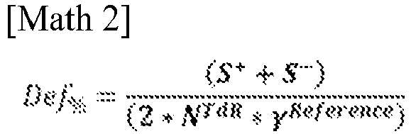
- the deformation of the pneumatic casing subjected to a load is determined by the following formula:
- S + corresponds to the energy density calculated from the material points of the development of the tire , which has a precise instant T, include those of the contact area or in its immediate vicinity. Indeed these have an absolute acceleration close to zero when crossing the contact area, they are therefore necessarily lower than the threshold A.
- the energy density S + corresponds to the energy density of the others development points of the tire and in particular those outside the contact patch.
- the deformation of the tire casing subjected to a load is determined by the following formula:
- the delimitation of the first signal on a number N ToR is carried out by the passage of the first signal below or above a threshold less than or equal to half the value of the acceleration of reference ⁇ reference .
- the first signal is used to delimit the latter over an integer number of revolutions of the wheel.
- the acceleration signal in the radial direction of a pneumatic casing subjected to a load will necessarily tend towards zero when the sensor crosses the contact area if the earth's gravity signal is neglected as for high rotational speeds.
- the first signal will necessarily pass at the level of a threshold situated below at least half of the reference acceleration ⁇ reference .
- the first signal will pass this threshold twice per revolution of the wheel.
- the threshold A is a function of the reference acceleration ⁇ reference .
- Threshold A makes it possible to dissociate the positive and negative energy densities of the method.
- any measurement signal is noisy. It is possible to filter or smooth this signal in real time, but at the risk of losing information, in particular the dynamics of passage through the contact area. By definition, this noise has a substantially zero mean value. And if, in theory, it should not or little affect the calculation of the energy densities S + and S - , it is likely to disturb the classification in S + or S - , and therefore distort the final result.
- this threshold A is to make it possible to arrange the variations between the wheel revolution signal and the reference acceleration according to one or other of the energy densities, taking into account the variations of the wheel revolution signal due to disturbances and a poor signal/noise ratio, these disturbances possibly coming from the macro-roughness of the road, specific obstacles encountered on the road, vibrations specific to the tire or to the vehicle on which it is mounted, or minor malfunctions of the measurement chain inherent to the nature and quality of the electronic components used.
- the wheel revolution signal and the reference acceleration depend on the rotational speed W of the mounted assembly and on the radial position of the sensor, it seems appropriate to make the threshold value A dependent on the reference acceleration for s free from these disturbances which could pollute the desired precision.
- the factor C is greater than or equal to 0.5 and less than or equal to 0.9.
- This value of the factor C makes it possible both to dissociate the positive and negative energy density on the turn of the wheel signal. Indeed, when passing through the contact area, the wheel revolution signal tends towards zero. Additionally, the transition to level of entry and exit of the contact area is very strong, very fast and of a profile that is always more or less identical. Thus, a value of 0.5 makes it possible not to reduce too much the number of measurement points which will be assigned to the negative energy density S ⁇ or to increase those which are assigned to S + . Indeed, the objective of the method is to use a low spatial discretization. Generally, few measurement points are located at the level of the transition zone.
- C a value of C equal to one is the theoretical value which makes it possible to dissociate the points between the two possible energy densities. If this is ideal on smooth floors with optimal conditions minimizing disturbances on the measurement chain. The slightest disturbance can impact the precision required on the result.
- the driving speed is beyond the threshold value, it is easy to dissociate the wheel revolution signal with respect to the threshold value A and this regardless of the vagaries in the wheel revolution signal such as, for example , high macro-roughness of the pavement, electromagnetic disturbances in the measurement chain, vibrations at the level of the tire casing.
- this also makes it possible to more clearly identify the gravity signal in the wheel rotation signal.
- ⁇ reference R ⁇ W 2
- the reference acceleration ⁇ reference corresponds to a neutral state of the pneumatic envelope for which the load is zero. In practice, this results in a mounted assembly comprising the mounted assembly which rolls without deforming on the ground in order to constitute a contact area. Finally, this corresponds to the acceleration that the sensor would experience if it were mounted on the pneumatic casing, which rotates freely around its natural axis of rotation.
- the reference acceleration ⁇ reference is then simply the centrifugal acceleration undergone by the sensor mounted on the freely rotating pneumatic casing.
- the identification of the reference acceleration then requires the determination of two parameters, the radial position of the sensor relative to the natural axis of rotation and the speed of rotation W of the pneumatic casing on which the sensor is fixed.
- the determination of the reference acceleration ⁇ reference is defined by the mean value of the wheel rotation signal Sig TdR .
- the method estimates that in its state of free rotation at the speed of rotation W, the pneumatic casing or any sensor attached to it undergoes a centrifugal acceleration proportional to its radial position with respect to the natural axis of rotation.
- the pneumatic casing when loaded by the crushing of the pneumatic casing on a rigid ground, the pneumatic casing is deformed so as to distribute the deformation energy generated by this load between two situations.
- the first situation corresponds to the condition of displacement imposed at the level of the contact area tending to reduce the centrifugal energy.
- the other situation corresponds to the energy condition imposed on the pneumatic envelope outside the contact area.
- the imposed energy is then the complement of the decrease in centrifugal energy corresponding to the first situation. Therefore, the mean value of the wheel revolution signal, over an integer number of wheel revolutions, whether or not the pneumatic casing is subjected to a load Z, corresponds to the centrifugal acceleration undergone by the sensor.
- a correction Corr is applied to the wheel revolution signal Sig TdR to take into account the effect of earth's gravity.
- the correction of the earth's gravity makes it possible to minimize the error on the deformation of the tire casing, in particular for low rolling speeds W.
- the sensor during the rolling of the pneumatic envelope, makes a revolution around the natural axis of rotation.
- the output signal of the sensor being proportional to the radial acceleration will be polluted by the earth's gravity.
- the earth's gravity will generate a sinusoidal signal of amplitude g which is a function of the altitude of the sensor in the reference frame of the Earth. It is therefore necessary to remove this parasitic signal Corr from the wheel revolution signal Sig TdR , which requires a readjustment of the wheel revolution signal with respect to an angular position of the tire casing.
- the acquisition of the first signal is carried out at a constant sampling frequency and the spatial discretization of sampling of the first signal is less than 6 degrees, preferentially less than 3 degrees, very preferentially less than 1 degree .
- the senor For example, if it is desired that the evaluation of the deformation of the pneumatic envelope take place at the level of the mounted assembly, the sensor must be associated with an electronic device comprising a microcontroller, a memory space, a battery and a clock. Then, the spatial discretion envisaged with a constant sampling frequency makes it possible to carry out elementary operations at the level of the microcontroller while minimizing the consumption of the battery. In addition, the minimum discretization of the order of 60 points per turn of the wheel makes it possible to limit the number of operations and of transfer to the memory space. However, the precision obtained on the deformation of the pneumatic envelope is good while having saved the battery of the electronic component. This makes it possible to store or transfer only intermediate scalar values of the method.
- the deformation of the tire casing subjected to a load is determined by the following formula: Or Or
- the numerator and the denominator of the formula for calculating Def % advantageously show a measurement made by the same sensor, which means that the result will be insensitive to any drift in the characteristics of this sensor induced by external elements.
- a pneumatic casing For the implementation of the invention, it is necessary to equip a pneumatic casing with an electronic component comprising a sensor, a microcontroller, a clock, a memory space and an energy storage means, and means of Radio Frequency communications in transmission and possibly in reception.
- the pneumatic casing comprises a crown, two sides and two beads of revolution around a natural axis of rotation.
- the envelope also comprises a median plane equidistant from the two beads, the intersection of the median plane and the natural axis of rotation defining a wheel center.
- the sensor is fixed to the pneumatic casing in line with the crown, in line with a rib or a longitudinal groove which are zones of homogeneous rigidity, at a fixed radial position R with respect to the natural axis of rotation.
- the sensor is adapted to generate at least one output signal proportional to the normal acceleration at the top undergone by the sensor in the pneumatic envelope.
- this sensor can be single-axis, in which case it must be positioned radially. It can also also consist of a plurality of single-axis sensors. In this case, it is appropriate to clearly identify the orientation of each of the single-axis sensors with respect to the marker of the pneumatic casing in order to reconstruct the normal acceleration at the top of the pneumatic casing.
- the sensor takes into account the DC component and the AC component of the acceleration.
- the DC component will be evaluated as the centrifugal acceleration of the sensor relative to the natural axis of rotation of the pneumatic envelope.
- the sensor in the case of taking the DC component into account can be a piezoresistive or capacitive technology accelerometer.
- the electronic component is powered by the energy storage means, is controlled by the microcontroller using the clock and in which are also implemented the calculation algorithms which make it possible to determine, for example, the state of deformation of the tire using the signals from the sensor element.
- the transmitting RF communication means are used to transmit the calculated information, and the receiving means to receive operating instructions or useful information in the calculation algorithms.
- this electronic device includes or is associated with other measurement elements (such as pressure, temperature, level of wear, distance traveled, etc.) in order to pool the devices and optimize the implementation costs.
- the sensor is started via the microcontroller when the tire envelope is in rolling condition.
- a rotational speed threshold value W from which the acquisition of a signal at the output of the sensor is carried out.
- the electronic device has a memory space adapted to the type of analysis that one wishes to perform. In fact, the capacity of this memory space is predefined according to the use of the electronic component. It is the microcontroller which controls the storage of the values of the sensor towards the memory space. In addition, the microcontroller is able to perform elementary mathematical and logical operations on a reduced number of data. If the mathematical and logical operations are more complex or the number of data to be handled becomes substantial, the microcontroller is replaced by a microprocessor. Finally, the electronic component is supplied with energy by a storage means. The simplest means of storage is the use of a battery. However, a large capacity rechargeable using a piezoelectric element could be envisaged.
- the frequency range of the electronic component makes it possible to cover a wide band of rotational speed W with a spatial discretization of minus 6 degrees.
- the sampling frequency is adaptive on command or in response to a signal such as for example the speed of rotation W of the pneumatic casing.
- the electronic device contains or and able to obtain the identification of the pneumatic envelope. This information is useful for choosing a set of useful data for calculation algorithms at the level of the electronic device. If the electronic component must obtain the identification of the tire or receive commands to perform a measurement, the electronic component is equipped with a radiofrequency reception means. This operates in the low frequency range, ideally at a frequency of 125KHz in order to overcome disturbances generated by the metal zones of the tire casing and its close environment in the vehicle.
- the electronic component has radiofrequency emission means, specifically in the UHF band (acronym for Ultra High Frequencies), in particular around 433 MHz or 900 MHz or the so-called BLE band (acronym in English for Bluetooth Low Emission) which constitute free frequency bands.
- the UHF band makes it possible to have reduced antenna sizes facilitating the integration of the electronic component within the pneumatic envelope.
- This transmission communication is useful for transmitting data from the method to the vehicle or outside the vehicle. It is possible either to transmit the data train corresponding to the acquisition of the wheel revolution signal or to transmit intermediate results which will have been calculated at the level of the electronic component.
- This second transmission mode is necessarily less costly in terms of energy for the electronic component since the data flow is less consequent.
- the radiofrequency emission is an energy-consuming item with respect to mathematical and logical operations.
- Fig 1 presents a first raw signal 1bis in gray corresponding to the normal acceleration at the top of a pneumatic envelope of the heavy goods vehicle type rolling at a constant rotational speed W.
- the curve 1bis passes through a value almost zero.
- This periodic phenomenon corresponds to the crossing of the contact area of the pneumatic casing by the sensor.
- the transition between the passage of the sensor between the contact area of the tire and the other part of the tire envelope takes place abruptly through falling or rising edges depending on whether one is entering or leaving the tire. the contact area.
- the first signal 1bis at a scale of the order of the revolution of the wheel follows a carrier, the first signal 1bis oscillates at a higher frequency than the frequency of the revolution of the wheel around this carrier.
- the curve indexed 1 in black represents the same accelerometric signal corrected only for the earth's gravity which will be called first corrected signal 1.
- the correction here is sinusoidal by having phased the correction on a point located in the center of the contact area , that is to say at an equal distance from the two edges delimiting the part of the signal whose value is almost zero. It is observed that the first signal 1 is flatter between the zones characterizing the contact area. It is preferable to perform the various steps of the method on this first corrected signal 1.
- Fig 2 presents the method for detecting the wheel revolution signal 2. From the first signal 1, here corrected to better explain the example, a threshold E is determined, illustrated by the dotted line 3. A series of increments I are identified when that the first signal 1 crosses the dotted line 3 for example from below, which physically corresponds to an exit from the contact area by the sensor integrally connected in rotation to the pneumatic casing. The first wheel revolution signal 2 is then delimited between a first increment, here Ii, and a second increment, here I 3 .
- the wheel revolution signal here represents the accelerometric signal from the sensor over two complete wheel revolutions.
- the threshold value E represented by the dotted line 3 was evaluated in our case on a part of the first signal 1 with a variable sampling frequency. On this part of the first signal 1, the discretized maximum value obtained, which is called MAX, is extracted. The threshold value E is then a value between 10 and 50% of the MAX value, in our case, this value is around 50%.
- the reference acceleration ⁇ reference which is represented by the solid line 4 in black is calculated. Its evaluation is made in real time, by accumulating the values of the increments u of the first wheel revolution signal. wheel which is, at the end of the wheel revolution signal, divided by the number of increments of the first wheel revolution signal. Of course, the calculation can also be done after the complete recording of the wheel revolution signal 2 has been recorded and stored in memory.
- Fig.3 presents a first signal 1, previously corrected for the earth's gravity corresponding to the normal acceleration at the top of a pneumatic envelope of the heavy goods vehicle type rolling at a variable speed of rotation W.
- thresholds E represented by the dotted line 3, for the wheel revolution signal 2 in light gray.
- the first threshold E makes it possible to identify the increments I corresponding for example to the exit from the contact area by the sensor.
- the wheel revolution signal Sig TdR is limited to one wheel revolution, which is preferable for limiting the errors linked to the variation of the rotational speed W of the tire casing.
- the threshold E was chosen so that it corresponds to half of the reference acceleration of the first signal delimited over an integer number of wheel revolutions carried out before the wheel revolution signal 2.
- Fig 4 is an illustration to explain the calculation of the positive S+ and negative S- energy densities on a revolution of the wheel signal 10 corresponds to a single revolution of the wheel when the speed of rotation W is constant.
- the method is identical if the speed of rotation W is variable or if the wheel revolution signal is delimited over several wheel revolutions.
- the threshold A is determined as being here the product of a value C, here equal to 1.0, by the reference acceleration ⁇ reference identified on the wheel revolution signal in post processing of the acquisition of the wheel revolution signal.
- This threshold is materialized by the continuous line 11.
- a value of C of the order of 0, 8 or 0.9 can be used. This value C must be fixed for all the steps of the method.
- the positive S + or negative S - energy densities are calculated as the sum of the absolute values of the differences between the wheel revolution signal 10 and the reference acceleration ⁇ reference , represented by the continuous curve 11. Necessarily, the delimited surface by the surfaces S + is equal to the surface delimited by the surface S - .
Description
La présente invention concerne les méthodes d'obtention de la déformation d'une enveloppe pneumatique d'un ensemble monté soumis à une charge en condition de roulage.The present invention relates to methods for obtaining the deformation of a pneumatic casing of a mounted assembly subjected to a load in rolling condition.
Pour le domaine des dispositifs et des méthodes de mesure de la déformation de l'ensemble monté, ceux-ci peuvent servir à caractériser le résultat de la déformation de l'enveloppe pneumatique due à la charge appliquée. Ainsi, les dispositifs et les méthodes cherchent à caractériser principalement l'empreinte au sol du pneumatique que l'on nomme aire de contact. En effet, la géomètre ou la répartition de contraintes au sein de cette aire de contact sont directement liées à la charge appliquée sur l'enveloppe pneumatique moyennant éventuellement la pression de gonflage de l'ensemble monté.For the field of devices and methods for measuring the deformation of the mounted assembly, these can be used to characterize the result of the deformation of the pneumatic casing due to the applied load. Thus, the devices and methods seek to characterize mainly the footprint of the tire on the ground, which is referred to as the contact area. Indeed, the surveyor or the distribution of stresses within this contact area are directly linked to the load applied to the pneumatic casing possibly by means of the inflation pressure of the mounted assembly.
Cette aire de contact qui ne représente qu'un pourcentage minime de la périphérie de l'enveloppe pneumatique en condition monté gonflé est aussi très sensible à divers paramètres comme la macrorugosité du sol ou les irrégularités présentes sur le sol par exemple. En effet, la zone de contact réelle entre l'enveloppe pneumatique et le sol peut alors correspondre aux sommets des indenteurs caractérisant la macrorugosité du sol. Ainsi, la répartition des contraintes dans l'enveloppe pneumatique est modifiée pouvant influer sur les dimensions de l'aire de contact.This contact area, which represents only a minimal percentage of the periphery of the tire in the mounted, inflated condition, is also very sensitive to various parameters such as the macroroughness of the ground or the irregularities present on the ground, for example. In fact, the real contact zone between the pneumatic casing and the ground can then correspond to the vertices of the indenters characterizing the macroroughness of the ground. Thus, the distribution of the stresses in the pneumatic casing is modified, which can influence the dimensions of the contact area.
De plus, la détermination précise des dimensions de l'aire de contact est difficile à obtenir en condition de roulage. Classiquement en roulage, l'aire de contact se caractérise à l'aide de signaux représentatifs de la déformation de l'enveloppe pneumatique. Ceux-ci se manifestent par un saut important de la grandeur observée traduisant le passage de l'enveloppe pneumatique d'une forme toroïdale libre à une forme toroïdale partiellement écrasée à déplacement imposé. En effet, le sol constitue alors une condition aux limites de type déplacement imposé pour les points matériels de l'enveloppe pneumatique. Il est alors difficile d'identifier les points d'entrée ou de sortie exacts de l'aire de contact, d'autant plus qu'ils varient légèrement avec la nature du sol. De plus, l'aire de contact ne représente qu'une partie du développement de l'enveloppe pneumatique classiquement entre 1/20 et 1/10 du développement de la bande de roulement. Afin d'obtenir une image précise de cette portion du pneumatique, il faut disposer d'une discrétisation fine au niveau du signal de déformation. Ceci nécessite des espaces mémoires conséquents, des fréquences spatiales d'échantillonnage élevées au moins au niveau de l'aire de contact, et la mesure sur de nombreux tours de roue pour minimiser la dispersion liée au sol déjà évoquée, ce qui est consommateur en énergie.In addition, the precise determination of the dimensions of the contact area is difficult to obtain in driving conditions. Conventionally in rolling, the contact area is characterized using signals representative of the deformation of the tire casing. These are manifested by a significant jump in the magnitude observed reflecting the passage of the pneumatic envelope from a free toroidal shape to a partially crushed toroidal shape with imposed displacement. Indeed, the ground then constitutes a boundary condition of the imposed displacement type for the material points of the pneumatic envelope. It is then difficult to identify the exact entry or exit points of the contact area, especially since they vary slightly with the nature of the ground. In addition, the contact area represents only part of the development of the pneumatic envelope, typically between 1/20 and 1/10 of the development of the tread. In order to obtain a precise image of this portion of the tire, it is necessary to have a fine discretization at the level of the deformation signal. This requires substantial memory spaces, high spatial sampling frequencies at least at the level of the contact area, and measurement over many revolutions of the wheel to minimize the dispersion linked to the ground already mentioned, which consumes energy. .
On connait dans l'état de la technique, le document
La présente invention porte sur un procédé qui permet une évaluation précise de la déformation de l'enveloppe pneumatique en condition de roulage quel que soit la nature du sol tout en économisant l'énergie du dispositif de mesure.The present invention relates to a method which allows an accurate evaluation of the deformation of the tire casing in running condition whatever the nature of the ground while saving the energy of the measuring device.
L'invention est définie par le jeu de revendications ci-jointes.The invention is defined by the appended set of claims.
L'invention porte sur une méthode d'obtention de la déformation d'une enveloppe pneumatique soumise à une charge, dans un état gonflé et chargé tournant à une vitesse de rotation W. L'enveloppe pneumatique ayant un sommet, deux flancs et deux bourrelets de révolution autour d'un axe naturel de rotation et un plan médian, l'intersection du plan médian et de l'axe naturel de rotation définit un centre roue. La méthode comprend les étapes suivantes :
- Fixer au moins un capteur sur l'enveloppe pneumatique au droit du sommet ayant une position radiale R par rapport à l'axe naturel de rotation, apte à générer au moins un signal de sortie proportionnel à l'accélération subie par ledit capteur dans l'enveloppe pneumatique;
- Réaliser l'acquisition d'un premier signal représentant l'amplitude de l'accélération selon la direction normale au sommet lors d'un roulage à la vitesse de rotation W ;
- Délimiter le premier signal sur un nombre NTdR de tours de roue, NTdR étant supérieur ou égal à 1.0, préférentiellement NTdR est un entier, afin de construire un signal tour de roue Sig TdR;
- Déterminer une accélération de référence γreference fonction de la vitesse de rotation W et de la position du au moins un capteur ;
- Définir une première densité d'énergie S qui est fonction du signal tour de roue SigTdR et de l'accélération de référence γreference, nommée S+ lorsque le signal tour de roue est supérieur à un seuil A, ou nommée S- lorsque le signal tour de roue est inférieur ou égale audit seuil A ;
- Identifier la déformation de l'enveloppe pneumatique Def% générée par la charge comme une fonction de l'accélération de référence γreference et de la première densité d'énergie S liées à la position du au moins un capteur.
- Fix at least one sensor on the pneumatic envelope to the right of the top having a radial position R with respect to the natural axis of rotation, capable of generating at at least one output signal proportional to the acceleration undergone by said sensor in the pneumatic envelope;
- Carry out the acquisition of a first signal representing the amplitude of the acceleration in the direction normal to the vertex during rolling at the speed of rotation W;
- delimiting the first signal over a number N TdR of wheel revolutions, N TdR being greater than or equal to 1.0, preferably N TdR is an integer, in order to construct a wheel revolution signal Sig TdR ;
- Determine a reference acceleration γ reference depending on the speed of rotation W and the position of at least one sensor;
- Define a first energy density S which is a function of the wheel revolution signal Sig TdR and the reference acceleration γ reference , named S + when the wheel revolution signal is greater than a threshold A, or named S - when the wheel revolution signal is less than or equal to said threshold A;
- Identify the deformation of the pneumatic envelope Def % generated by the load as a function of the reference acceleration γ reference and of the first energy density S related to the position of at least one sensor.
Comme dans l'état de la technique, il faut obtenir l'accélération d'un point matériel du pneumatique. Ici, il est important que l'accélération corresponde à sa composante normale au sommet puisque c'est cette composante qui est l'information principale de la déformation de l'enveloppe pneumatique. De plus il est préférable que cela soit l'accélération absolue du point matériel et non pas seulement sa composante alternative autour de la composante continue comme dans certaines méthodes de l'état de l'art. Cependant, si l'accélération délivrée par le capteur ne comprend pas la composante continue, il faut ajouter artificiellement cette composante continue comme étant l'accélération centrifuge résultant d'une position radiale R et d'une vitesse de rotation W. Préférentiellement, la position radiale R du capteur est déterminée dans un état gonflé et non chargé de l'ensemble monté. Ensuite, il faut délimiter le signal d'accélération sur une portion de tour de roue. Ici, il est important de pouvoir identifier, soit au travers du signal du capteur, soit du seul premier signal soit à l'aide d'un codeur tour de roue, le nombre de tours de roue lors de la délimitation du premier signal. Puis, on définit la vitesse de rotation W comme étant la vitesse de rotation moyenne sur la durée du signal tour de roue si la variation de vitesse de rotation est faible sur le signal tour de roue, c'est-à-dire inférieure à 15% par rapport à la vitesse moyenne. Si l'enveloppe pneumatique est à vitesse constante, c'est préférable car on élimine de nombreuses sources d'erreurs potentielles.As in the state of the art, it is necessary to obtain the acceleration of a material point of the tire. Here, it is important that the acceleration corresponds to its normal component at the top since it is this component which is the main information of the deformation of the pneumatic envelope. Moreover, it is preferable that this be the absolute acceleration of the material point and not only its alternating component around the continuous component as in certain methods of the state of the art. However, if the acceleration delivered by the sensor does not include the DC component, it is necessary to artificially add this DC component as being the centrifugal acceleration resulting from a radial position R and a speed of rotation W. Preferably, the position radial R of the sensor is determined in an inflated and unloaded state of the assembly mounted. Then, it is necessary to delimit the acceleration signal on a portion of the revolution of the wheel. Here, it is important to be able to identify, either through the signal from the sensor, or from the first signal alone, or using a wheel revolution encoder, the number of wheel revolutions during the delimitation of the first signal. Then, the rotational speed W is defined as being the average rotational speed over the duration of the wheel revolution signal if the rotational speed variation is low on the wheel revolution signal, that is to say less than 15 % compared to the average speed. If the pneumatic envelope is at constant speed, it is preferable because many sources of potential errors are eliminated.
Ensuite, la simple comparaison du niveau d'accélération absolue du signal tour de roue avec une accélération de référence liée à la position radiale du capteur et au niveau de vitesse de rotation W permet de générer une densité d'énergie S. L'amplitude du signal tour de roue par rapport à un seuil A qui peut, par exemple, simplement être l'accélération de référence génère potentiellement un doublet de densités d'énergie de déformation positive et négative (S+, S-) à partir du signal tour de roue. Ainsi, la méthode ne fait que définir une densité d'énergie de déformation de l'enveloppe pneumatique et la distribuer dans deux sous-ensembles selon sa position par rapport au seuil A Ce sont des opérations simples à réaliser qui consomment peu de ressources. Bien entendu, pour être représentative, la méthode part de l'accélération absolue qui permet une comparaison aisée avec l'accélération de référence pour identifier le doublet de densités d'énergie.Then, the simple comparison of the level of absolute acceleration of the wheel revolution signal with a reference acceleration linked to the radial position of the sensor and to the level of rotational speed W makes it possible to generate an energy density S. The amplitude of the wheel revolution signal relative to a threshold A which may, for example, simply be the reference acceleration potentially generates a doublet of positive and negative strain energy densities (S + ,S- ) from the wheel revolution signal wheel. Thus, the method only defines a deformation energy density of the tire casing and distributes it in two sub-assemblies according to its position with respect to the threshold A. These are simple operations to carry out which consume few resources. Of course, to be representative, the method starts from the absolute acceleration which allows an easy comparison with the reference acceleration to identify the doublet of energy densities.
Enfin, la méthode détermine la déformation de l'enveloppe pneumatique comme une fonction de la densité d'énergie calculée qu'elle norme sur la durée du signal tour de roue qui subirait une accélération de référence. Ainsi, la déformation représente une normalisation de l'énergie de déformation sur un tour de roue physique de l'enveloppe pneumatique. De ce fait, on identifie un invariant énergétique lié à la déformation de l'enveloppe pneumatique soumis à une charge en condition de roulage. Bien entendu, un seul tour de roue est nécessaire à la méthode. Cependant de façon préférentielle, le nombre de tours de roue sera d'au moins 5, voire 10 afin de moyenner les résultats ce qui permettra de s'affranchir de phénomènes aléatoires sur le signal comme par exemple des obstacles sur la chaussée sur laquelle roule l'enveloppe pneumatique. Ainsi, la précision de la méthode s'en trouve améliorée en mode industriel.Finally, the method determines the deformation of the tire casing as a function of the calculated energy density which it normalizes over the duration of the wheel revolution signal which would undergo a reference acceleration. Thus, strain represents a normalization of the strain energy over one physical wheel revolution of the tire casing. As a result, an energy invariant linked to the deformation of the tire casing subjected to a load in rolling condition is identified. Of course, only one turn of the wheel is necessary for the method. However, preferably, the number of revolutions of the wheel will be at least 5, or even 10 in order to average the results, which will make it possible to overcome random phenomena on the signal such as, for example, obstacles on the roadway on which the tire rolls. Thus, the accuracy of the method is improved in industrial mode.
Préférentiellement, la déformation de l'enveloppe pneumatique soumise à une charge est déterminée par la formule suivante :

Ainsi, c'est une formule élémentaire de la déformation de l'enveloppe pneumatique qui s'applique soit à S+, soit à S- Nécessairement, S- correspond à la densité d'énergie calculées à partir des points matériels du développement du pneumatique , qui a un instant T précis, comprennent ceux de l'aire de contact ou à sa proximité immédiate. En effet ceux-ci ont une accélération absolue proche de zéro lors de la traversée de l'aire de contact, ils sont donc nécessairement inférieur au seuil A. Par défaut la densité d'énergie S+ correspond à la densité d'énergie des autres points du développement du pneumatique et notamment ceux en dehors de l'aire de contact. Lorsque l'accélération de référence γreference à partir de laquelle sont calculées les densités d'énergie S+ et S- est égale à la valeur moyenne du signal tour de roue SigTdR la déformation évaluée à l'aide de S+ ou de S-, on obtient le même résultat aux incertitudes de mesure prés. Cela met en évidence que l'on se trouve en présence d'un invariant lié à la déformation de l'enveloppe pneumatique soumise à une charge Z. Dans le cas où on n'utilise que S+, il n'est pas nécessaire d'avoir une discrétisation spatiale élevée puisque les variations en dehors de l'aire de contact sont moins fortes. Cela a pour avantage de réduire la fréquence d'échantillonnage nécessaire du dispositif électronique couplée au capteur ou de pouvoir obtenir une information précise sur la déformation de l'enveloppe pneumatique a des vitesse de rotations élevées.Thus, it is an elementary formula of the deformation of the pneumatic envelope which applies either to S + , or to S - Necessarily, S - corresponds to the energy density calculated from the material points of the development of the tire , which has a precise instant T, include those of the contact area or in its immediate vicinity. Indeed these have an absolute acceleration close to zero when crossing the contact area, they are therefore necessarily lower than the threshold A. By default the energy density S + corresponds to the energy density of the others development points of the tire and in particular those outside the contact patch. When the reference acceleration γ reference from which the energy densities S + and S - are calculated is equal to the average value of the wheel revolution signal Sig TdR the deformation evaluated using S + or S - , the same result is obtained within measurement uncertainties. This highlights that we are in the presence of an invariant linked to the deformation of the pneumatic envelope subjected to a load Z. In the case where only S + is used, it is not necessary to have a high spatial discretization since the variations outside the contact area are less strong. This has the advantage of reducing the necessary sampling frequency of the electronic device coupled to the sensor or of being able to obtain precise information on the deformation of the pneumatic casing at high rotational speeds.
Très préférentiellement, la déformation de l'enveloppe pneumatique soumise à une charge est déterminée par la formule suivante :
Dans ce cas, il faut cumuler l'énergie de déformation du pneumatique sur la totalité du développement du pneumatique. Afin de minimiser à coup sur les incertitudes de mesure, on utilise alors l'ensemble des points de mesure de l'accélération normale au sommet pour déterminer la déformation de l'enveloppe pneumatique ce qui permet de réduire la consommation énergétique comparativement à une analyse avec une fréquence d'échantillonnage élevée.In this case, it is necessary to accumulate the deformation energy of the tire over the entire development of the tire. In order to minimize the measurement uncertainties, we then use all the measurement points of the normal acceleration at the top to determine the deformation of the tire envelope, which makes it possible to reduce the energy consumption compared to an analysis with a high sampling frequency.
Selon un mode de réalisation privilégié, la délimitation du premier signal sur un nombre NTdR s'effectue par le passage du premier signal en dessous ou au-dessus d'un seuil inférieur ou égal à la moitié de la valeur de l'accélération de référence γreference.According to a preferred embodiment, the delimitation of the first signal on a number N ToR is carried out by the passage of the first signal below or above a threshold less than or equal to half the value of the acceleration of reference γ reference .
Dans ce mode de réalisation, on n'emploie que le premier signal pour délimiter celui-ci sur un nombre entier de tour de roue. En effet, le signal d'accélération selon la direction radiale d'une enveloppe pneumatique soumise à une charge va nécessairement tendre vers zéro lors de la traversée de l'aire de contact par le capteur si on néglige le signal de la gravité terrestre comme pour des vitesses de rotation élevées. Ainsi, le premier signal passera nécessairement au niveau d'un seuil situé en dessous au moins de la moitié de l'accélération de référence γreference. En fait, le premier signal passera à deux reprises au niveau de ce seuil par tour de roue. Ces passages correspondent schématiquement à la zone d'entrée et de sortie de l'aire de contact. De ce fait, on ne prenant que l'un des sens de passage, passage en dessous de ce seuil ou au-dessus de ce seuil, on obtient un indicateur de tour de roue à partir du premier signal du capteur. Du fait de la discrétisation spatiale grossière qui peut être employée, cette détection est suffisante pour la méthode d'évaluation de la déformation de l'enveloppe pneumatique.In this embodiment, only the first signal is used to delimit the latter over an integer number of revolutions of the wheel. In fact, the acceleration signal in the radial direction of a pneumatic casing subjected to a load will necessarily tend towards zero when the sensor crosses the contact area if the earth's gravity signal is neglected as for high rotational speeds. Thus, the first signal will necessarily pass at the level of a threshold situated below at least half of the reference acceleration γ reference . In fact, the first signal will pass this threshold twice per revolution of the wheel. These passages correspond schematically to the entry and exit zone of the contact area. Therefore, taking only one of the directions of passage, passage below this threshold or above this threshold, a wheel revolution indicator is obtained from the first signal from the sensor. Due to the coarse spatial discretization that can be used, this detection is sufficient for the method of evaluating the deformation of the tire casing.
Avantageusement, le seuil A est fonction l'accélération de référence γreference.Advantageously, the threshold A is a function of the reference acceleration γ reference .
Le seuil A permet de dissocier les densités d'énergie positif et négatif de la méthode.Threshold A makes it possible to dissociate the positive and negative energy densities of the method.
En effet, tout signal de mesure est bruité. Il est possible de filtrer, ou lisser ce signal en temps réel, mais au risque de perdre de l'information, notamment la dynamique du passage dans l'aire de contact. Par définition, ce bruit est de valeur moyenne sensiblement nulle. Et si, en théorie, il ne doit pas ou peu affecter le calcul des densités d'énergie S+ et S-, il est susceptible de perturber la classification dans S+ ou S-, et donc fausser le résultat final. Ce seuil A a pour objectif de permettre de ranger les variations entre le signal de tour de roue et l'accélération de référence selon l'une ou l'autre des densités d'énergie, en tenant compte des variations du signal de tour de roue dues à des perturbations et un mauvais rapport signal/bruit, ces perturbations pouvant provenir de la macrorugosité de la route, d'obstacles ponctuels rencontrés sur la route, des vibrations propres au pneumatique ou au véhicule sur lequel il est monté, ou des petits dysfonctionnements électromagnétiques de la chaîne de mesure inhérents à la nature et la qualité des composants électroniques utilisés. Comme le signal tour de roue et l'accélération de référence dépendent de la vitesse de rotation W de l'ensemble monté et de la position radiale du capteur, il semble opportun de rendre dépendant la valeur seuil A de l'accélération de référence pour s'affranchir de ces perturbations qui pourrait polluer la précision souhaitée.Indeed, any measurement signal is noisy. It is possible to filter or smooth this signal in real time, but at the risk of losing information, in particular the dynamics of passage through the contact area. By definition, this noise has a substantially zero mean value. And if, in theory, it should not or little affect the calculation of the energy densities S + and S - , it is likely to disturb the classification in S + or S - , and therefore distort the final result. The purpose of this threshold A is to make it possible to arrange the variations between the wheel revolution signal and the reference acceleration according to one or other of the energy densities, taking into account the variations of the wheel revolution signal due to disturbances and a poor signal/noise ratio, these disturbances possibly coming from the macro-roughness of the road, specific obstacles encountered on the road, vibrations specific to the tire or to the vehicle on which it is mounted, or minor malfunctions of the measurement chain inherent to the nature and quality of the electronic components used. As the wheel revolution signal and the reference acceleration depend on the rotational speed W of the mounted assembly and on the radial position of the sensor, it seems appropriate to make the threshold value A dependent on the reference acceleration for s free from these disturbances which could pollute the desired precision.
Très avantageusement, le seuil A est fonction d'un facteur C selon la formule suivante : 
Préférentiellement, le facteur C est supérieur ou égal à 0,5 et inférieur ou égal à 0,9.Preferably, the factor C is greater than or equal to 0.5 and less than or equal to 0.9.
Cette valeur du facteur C permet à la fois de dissocier la densité d'énergie positive et négative sur le signal tour de roue. En effet, lors du passage dans l'aire de contact, le signal tour de roue tend vers zéro. De plus, la transition au niveau de l'entrée et la sortie de l'aire de contact est très forte, très rapide et d'un profil toujours sensiblement identique. Ainsi, une valeur de 0,5 permet de ne pas trop diminuer le nombre de points de mesure qui seront affectés à la densité d'énergie négative S- ou augmenter ceux qui sont affectés à S+. En effet, l'objectif de la méthode est d'employer une discrétisation spatiale peu élevée. Généralement, peu de points de mesure sont situées au niveau de la zone de transition. De ce fait, l'erreur commise sur S- et sur S+ est minime voire nulle si aucun point de mesure ne se trouve dans la zone de sélection correspondante à C entre 0,5 et 0,9. Elle sera en outre répétitive si on utilise un coefficient C figé proportionnel à γReference pour toutes les caractérisations, et l'erreur éventuellement induite sera reproductible donc transparente par rapport à un niveau de référence défini par ailleurs.This value of the factor C makes it possible both to dissociate the positive and negative energy density on the turn of the wheel signal. Indeed, when passing through the contact area, the wheel revolution signal tends towards zero. Additionally, the transition to level of entry and exit of the contact area is very strong, very fast and of a profile that is always more or less identical. Thus, a value of 0.5 makes it possible not to reduce too much the number of measurement points which will be assigned to the negative energy density S − or to increase those which are assigned to S + . Indeed, the objective of the method is to use a low spatial discretization. Generally, few measurement points are located at the level of the transition zone. As a result, the error committed on S − and on S + is minimal or even zero if no measurement point is in the selection zone corresponding to C between 0.5 and 0.9. It will also be repetitive if a fixed coefficient C proportional to γ Reference is used for all the characterizations, and any error induced will be reproducible and therefore transparent with respect to a reference level defined elsewhere.
A l'inverse, une valeur de C égale à un est la valeur théorique qui permet de dissocier les points entre les deux densités d'énergie possibles. Si cela est idéal sur des sols lisses avec des conditions optimales minimisant les perturbations sur la chaîne de mesure. La moindre perturbation peut impacter la précision requise sur le résultat.Conversely, a value of C equal to one is the theoretical value which makes it possible to dissociate the points between the two possible energy densities. If this is ideal on smooth floors with optimal conditions minimizing disturbances on the measurement chain. The slightest disturbance can impact the precision required on the result.
De façon préférentielle, l'acquisition du premier signal est effectuée pour une vitesse de rotation W supérieure ou égale à une vitesse de rotation seuil Wseuil définie par la formule suivante :
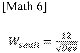
- où Dev est le développement de l'enveloppe pneumatique.
- where Dev is the development of the pneumatic envelope.
Ainsi, si la vitesse de roulage est au-delà de la valeur seuil, il est aisé de dissocier le signal tour de roue par rapport à la valeur seuil A et ce quels que soient les aléas dans le signal tour de roue comme, par exemple, une forte macrorugosité de la chaussée, des perturbations électromagnétiques dans la chaine de mesure, des vibrations au niveau de l'enveloppe pneumatique. De plus, cela permet aussi d'identifier plus nettement le signal de la gravité dans le signal tour de roue.Thus, if the driving speed is beyond the threshold value, it is easy to dissociate the wheel revolution signal with respect to the threshold value A and this regardless of the vagaries in the wheel revolution signal such as, for example , high macro-roughness of the pavement, electromagnetic disturbances in the measurement chain, vibrations at the level of the tire casing. In addition, this also makes it possible to more clearly identify the gravity signal in the wheel rotation signal.
Selon un premier mode de réalisation, la détermination de l'accélération de référence γreference s'effectue par la formule suivante : 
L'accélération de référence γreference correspond à un état neutre de l'enveloppe pneumatique pour lequel la charge est nulle. En pratique, cela se traduit par un ensemble monté comprenant l'ensemble monté qui roule sans se déformer au sol afin de constituer une aire de contact. Finalement, cela correspond à l'accélération que subirait le capteur si il était monté sur l'enveloppe pneumatique celle-ci tourne librement autour de son axe naturel de rotation.The reference acceleration γ reference corresponds to a neutral state of the pneumatic envelope for which the load is zero. In practice, this results in a mounted assembly comprising the mounted assembly which rolls without deforming on the ground in order to constitute a contact area. Finally, this corresponds to the acceleration that the sensor would experience if it were mounted on the pneumatic casing, which rotates freely around its natural axis of rotation.
De ce fait, l'accélération de référence γreference est alors simplement l'accélération centrifuge subie par le capteur monté sur l'enveloppe pneumatique tournant librement. L'identification de l'accélération de référence nécessite alors la détermination de deux paramètres, la position radiale du capteur par rapport à l'axe naturel de rotation et la vitesse de rotation W de l'enveloppe pneumatique sur laquelle est fixé le capteur.Therefore, the reference acceleration γ reference is then simply the centrifugal acceleration undergone by the sensor mounted on the freely rotating pneumatic casing. The identification of the reference acceleration then requires the determination of two parameters, the radial position of the sensor relative to the natural axis of rotation and the speed of rotation W of the pneumatic casing on which the sensor is fixed.
Selon un deuxième mode de réalisation la détermination de l'accélération de référence γreference est définie par la valeur moyenne du signal tour de roue SigTdR.According to a second embodiment, the determination of the reference acceleration γ reference is defined by the mean value of the wheel rotation signal Sig TdR .
En effet, en cas d'absence d'information sur la déformée de l'enveloppe pneumatique dans un état monté gonflé ce qui ne permet pas d'identifier exactement la position radiale du capteur sur l'enveloppe pneumatique, il est possible de déterminer l'accélération de référence à l'aide de la valeur moyenne du signal tour de roue SigTdR.Indeed, in the event of absence of information on the deformation of the pneumatic casing in an inflated mounted state, which does not make it possible to identify exactly the radial position of the sensor on the pneumatic casing, it is possible to determine the reference acceleration using the mean value of the wheel rotation signal Sig TdR .
En effet la méthode estime que dans son état de rotation libre à la vitesse de rotation W, l'enveloppe pneumatique ou tout capteur qui lui est attaché subi une accélération centrifuge proportionnelle à sa position radiale par rapport à l'axe naturel de rotation. De plus, lors de la mise sous charge par l'écrasement de l'enveloppe pneumatique sur un sol rigide, l'enveloppe pneumatique se déforme de façon à répartir l'énergie de déformation générée par cette charge entre deux situations. La première situation correspond à la condition de déplacement imposé au niveau de l'aire de contact tendant à diminuer l'énergie centrifuge. L'autre situation correspond à la condition d'énergie imposée sur l'enveloppe pneumatique hors de l'aire de contact. L'énergie imposée est alors le complémentaire de la diminution de l'énergie centrifuge correspondant à la première situation. De ce fait, la valeur moyenne du signal tour de roue , sur un nombre entier de tours de roue, que l'enveloppe pneumatique soit ou non soumis à une charge Z, correspond à l'accélération centrifuge subie par le capteur.In fact, the method estimates that in its state of free rotation at the speed of rotation W, the pneumatic casing or any sensor attached to it undergoes a centrifugal acceleration proportional to its radial position with respect to the natural axis of rotation. In addition, when loaded by the crushing of the pneumatic casing on a rigid ground, the pneumatic casing is deformed so as to distribute the deformation energy generated by this load between two situations. The first situation corresponds to the condition of displacement imposed at the level of the contact area tending to reduce the centrifugal energy. The other situation corresponds to the energy condition imposed on the pneumatic envelope outside the contact area. The imposed energy is then the complement of the decrease in centrifugal energy corresponding to the first situation. Therefore, the mean value of the wheel revolution signal, over an integer number of wheel revolutions, whether or not the pneumatic casing is subjected to a load Z, corresponds to the centrifugal acceleration undergone by the sensor.
Préférentiellement, ayant phasé le signal tour de roue SigTdR par rapport à une position angulaire de l'enveloppe pneumatique, une correction Corr est apportée au signal tour de roue SigTdR pour prendre en compte l'effet de la gravité terrestre.Preferably, having phased the wheel revolution signal Sig TdR with respect to an angular position of the tire casing, a correction Corr is applied to the wheel revolution signal Sig TdR to take into account the effect of earth's gravity.
La correction de la gravité terrestre permet de minimiser l'erreur sur la déformation de l'enveloppe pneumatique en particulier pour les vitesses de roulage W basses. En effet, le capteur, lors du roulage de l'enveloppe pneumatique, fait une révolution autour de l'axe naturel de rotation. Le signal de sortie du capteur étant proportionnel à l'accélération radiale sera pollué par la gravité terrestre. Sur un tour de roue, la gravité terrrestre va générer un signal sinusoïdal d'amplitude g qui est fonction de l'altitude du capteur dans le repère de la Terre. Il faut donc retirer ce signal parasite Corr du signal tour de roue SigTdR ce qui nécessite un recalage du signal tour de roue par rapport à une position angulaire de l'enveloppe pneumatique.The correction of the earth's gravity makes it possible to minimize the error on the deformation of the tire casing, in particular for low rolling speeds W. Indeed, the sensor, during the rolling of the pneumatic envelope, makes a revolution around the natural axis of rotation. The output signal of the sensor being proportional to the radial acceleration will be polluted by the earth's gravity. On one revolution of the wheel, the earth's gravity will generate a sinusoidal signal of amplitude g which is a function of the altitude of the sensor in the reference frame of the Earth. It is therefore necessary to remove this parasitic signal Corr from the wheel revolution signal Sig TdR , which requires a readjustment of the wheel revolution signal with respect to an angular position of the tire casing.
Bien entendu, plus la vitesse de rotation W de l'enveloppe pneumatique est élevée, plus l'accélération centrifuge subie par le capteur devient prédominant par rapport à ce signal parasite.Of course, the higher the speed of rotation W of the pneumatic casing, the more the centrifugal acceleration undergone by the sensor becomes predominant with respect to this parasitic signal.
Selon un premier mode de réalisation, la détermination des densités d'énergie négative S- et positive S+ s'éffectue à l'aide des formules suivantes :


- Où u est l'abscisse du signal tour de roue SigTDR.
- Where u is the abscissa of the Sig TDR wheel revolution signal.
Ainsi, dans le cas d'un signal continu, la détermination des densités d'énergie S+ et S- s'effectuent par les formules ci-dessus.Thus, in the case of a continuous signal, the determination of the energy densities S + and S - are carried out by the formulas above.
Selon un mode de réalisation particulier, l'acquisition du premier signal est effectuée à une fréquence d'échantillonnage constante et la discrétisation spatiale d'échantillonnage du premier signal est inférieure à 6 degrés, préférentiellement inférieure à 3 degrés, très préférentiellement inférieure à 1 degré.According to a particular embodiment, the acquisition of the first signal is carried out at a constant sampling frequency and the spatial discretization of sampling of the first signal is less than 6 degrees, preferentially less than 3 degrees, very preferentially less than 1 degree .
Par exemple si on souhaite que l'évaluation de la déformation de l'enveloppe pneumatique ait lieu au niveau de l'ensemble monté, il faut que le capteur soit associé à un organe électronique comprenant un microcontrôleur, un espace mémoire, une batterie et une horloge. Alors, la discrétion spatiale envisagée avec une fréquence d'échantillonnage constante permet de réaliser des opérations élémentaires au niveau du microcontrôleur en minimisant la consommation de la batterie. De plus, la discrétisation minimale de l'ordre de 60 points au tour de roue permet de limiter le nombre d'opérations et de transfert vers l'espace mémoire. Pour autant, la précision obtenue sur la déformation de l'enveloppe pneumatique est bonne tout en ayant économisé la batterie de l'organe électronique. Cela permet de ne stocker ou de ne transférer que des valeurs scalaires intermédiaires de la méthode.For example, if it is desired that the evaluation of the deformation of the pneumatic envelope take place at the level of the mounted assembly, the sensor must be associated with an electronic device comprising a microcontroller, a memory space, a battery and a clock. Then, the spatial discretion envisaged with a constant sampling frequency makes it possible to carry out elementary operations at the level of the microcontroller while minimizing the consumption of the battery. In addition, the minimum discretization of the order of 60 points per turn of the wheel makes it possible to limit the number of operations and of transfer to the memory space. However, the precision obtained on the deformation of the pneumatic envelope is good while having saved the battery of the electronic component. This makes it possible to store or transfer only intermediate scalar values of the method.
Selon un mode de réalisation très particulier la détermination des densités d'énergie négative S- et positive S+ sont obtenues à l'aide des formules suivantes :


- Où NU est le nombre total de points discrétisés sur le signal tour de roue SigTdR .
- Where N U is the total number of points discretized on the wheel revolution signal Sig TdR .
C'est une façon simple d'obtenir une valeur scalaire de chaque densité d'énergie à partir du signal discrétisé du signal tour de roue.It is a simple way to obtain a scalar value of each energy density from the discretized signal of the wheel revolution signal.
Selon un mode de réalisation très particulier l'accélération de référence γreference est définie par la formule suivante :

- Où NU est le nombre total de points discrétisés sur le signal tour de roue SigTdR
- Where N U is the total number of discretized points on the wheel revolution signal Sig TdR
Dans le cas où l'évaluation de l'accélération de référence γReference est évaluée comme la valeur moyenne du signal tour de roue sur un nombre fini de tour de roue, c'est une façon simple et rapide d'obtenir une évaluation de la grandeur scalaire.In the case where the evaluation of the reference acceleration γ Reference is evaluated as the average value of the wheel revolution signal over a finite number of wheel revolutions, this is a simple and quick way to obtain an evaluation of the scalar magnitude.
Selon un mode de réalisation préférentiel, la déformation de l'enveloppe pneumatique soumise à une charge est déterminée par la formule suivante :


En outre, en optant pour une évaluation de l'accélération de référence γreference sous la forme de la valeur moyenne du signal tour de roue on fait apparaitre avantageusement au numérateur et au dénominateur de la formule de calcul de Def% une mesure réalisée par le même capteur, ce qui signifie que le résultat sera insensible à toute dérive des caractéristiques de ce capteur induite par les éléments extérieurs.In addition, by opting for an evaluation of the reference acceleration γ reference in the form of the average value of the wheel rotation signal, the numerator and the denominator of the formula for calculating Def % advantageously show a measurement made by the same sensor, which means that the result will be insensitive to any drift in the characteristics of this sensor induced by external elements.
C'est la forme la plus simple et la plus élémentaire pour identifier la déformation de l'enveloppe pneumatique à partir des grandeurs discrétisés du signal tour de tour. Les trois formules sont théoriquement équivalentes aux erreurs générées par la discrétisation du signal tour de roue.This is the simplest and most elementary form for identifying the deformation of the pneumatic envelope from the discretized magnitudes of the turn signal. The three formulas are theoretically equivalent to the errors generated by the discretization of the wheel revolution signal.
L'invention sera mieux comprise à la lecture de la description qui va suivre dans le cas d'une application à des bandages pneumatiques. Cette application est donnée uniquement à titre d'exemple et faite en se référant aux figures annexées dans lesquelles :
- La
Fig 1 est l'exemple d'un premier signal de la méthode. - La
Fig 2 représente le signal tour de roue SigTDR et son identification à partir d'un premier signal. - La
Fig 3 représente le signal tour de roue SigTdR lors d'un roulage à vitesse de rotation W variable. - La
Fig 4 représente le second signal tour de roue SigTdR2 lors d'un roulage à vitesse de rotation W constante sur un tour.
- There
Fig 1 is the example of a first signal of the method. - There
Fig 2 represents the wheel revolution signal Sig TDR and its identification from a first signal. - There
Fig.3 represents the wheel revolution signal Sig TdR during rolling at variable rotational speed W. - There
Fig 4 represents the second wheel revolution signal Sig TdR2 during rolling at constant rotational speed W over one revolution.
Pour la mise en oeuvre de l'invention, il faut équiper une enveloppe pneumatique d'un organe électronique comprenant un capteur, un microcontrôleur, une horloge, un espace mémoire et un moyen de stockage d'énergie, et des moyens de communications Radio Fréquence en émission et éventuellement en réception. L'enveloppe pneumatique comprend un sommet, deux flancs et deux bourrelets de révolution autour d'un axe naturel de rotation. L'enveloppe comprend aussi un plan médian équidistant des deux bourrelets, l'intersection du plan médian et de l'axe naturel de rotation définissant un centre roue.For the implementation of the invention, it is necessary to equip a pneumatic casing with an electronic component comprising a sensor, a microcontroller, a clock, a memory space and an energy storage means, and means of Radio Frequency communications in transmission and possibly in reception. The pneumatic casing comprises a crown, two sides and two beads of revolution around a natural axis of rotation. The envelope also comprises a median plane equidistant from the two beads, the intersection of the median plane and the natural axis of rotation defining a wheel center.
Le capteur est fixé sur l'enveloppe pneumatique au droit du sommet, au droit d'un rib ou d'un sillon longitudinal qui sont des zones de rigidité homogène, à une position radiale R fixe par rapport à l'axe naturel de rotation. Le capteur est apte à générer au moins un signal de sortie proportionnel à l'accélération normale au sommet subie par le capteur dans l'enveloppe pneumatique. En fait, ce capteur peut être monoaxe, auquel cas, il faut le positionner de façon radiale. Il peut aussi être aussi constitué d'une pluralité de capteurs monoaxes. Dans ce cas, il convient de bien identifier l'orientation de chacun des capteurs monoaxes par rapport au repère de l'enveloppe pneumatique afin de reconstruire l'accélération normale au sommet de l'enveloppe pneumatique. Idéalement, le capteur prend en compte la composante continue et la composante alternative de l'accélération. Dans le cas où seule la composante alternative est mesurée par le capteur, il conviendra pour la mise en oeuvre de la méthode de construire artificiellement la composante continue. Pour cela, il faut alors identifier la vitesse de rotation W de l'enveloppe pneumatique en temps réel et connaitre avec précision la position radiale R du capteur. En effet, la composante continue sera évaluée comme l'accélération centrifuge du capteur par rapport à l'axe naturel de rotation de l'enveloppe pneumatique. Le capteur dans le cas de la prise en compte de la composante continue peut être un accéléromètre de technologie piezorésistive ou capacitive.The sensor is fixed to the pneumatic casing in line with the crown, in line with a rib or a longitudinal groove which are zones of homogeneous rigidity, at a fixed radial position R with respect to the natural axis of rotation. The sensor is adapted to generate at least one output signal proportional to the normal acceleration at the top undergone by the sensor in the pneumatic envelope. In fact, this sensor can be single-axis, in which case it must be positioned radially. It can also also consist of a plurality of single-axis sensors. In this case, it is appropriate to clearly identify the orientation of each of the single-axis sensors with respect to the marker of the pneumatic casing in order to reconstruct the normal acceleration at the top of the pneumatic casing. Ideally, the sensor takes into account the DC component and the AC component of the acceleration. In the case where only the AC component is measured by the sensor, it will be appropriate for the implementation of the method to artificially construct the DC component. For this, it is then necessary to identify the speed of rotation W of the pneumatic casing in real time and to know precisely the radial position R of the sensor. Indeed, the DC component will be evaluated as the centrifugal acceleration of the sensor relative to the natural axis of rotation of the pneumatic envelope. The sensor in the case of taking the DC component into account can be a piezoresistive or capacitive technology accelerometer.
L'organe électronique est alimenté par le moyen de stockage d'énergie, est piloté par le microcontrôleur à l'aide l'horloge et dans lequel sont aussi implantés les algorithmes de calcul qui permettent de déterminer par exemple l'état de déformation du pneumatique en utilisant les signaux issus de l'élément capteur. Les moyens de communication RF d'émission servent à transmettre les informations calculées, et ceux de réception de recevoir des instructions de fonctionnement ou des informations utiles dans les algorithmes de calcul. Idéalement, cet organe électronique comprends ou est associé d'autres éléments de mesures (tels que pression, température, niveau d'usure, distance parcourue, etc...) afin de mutualiser les organes et optimiser les coûts de mise en oeuvre.The electronic component is powered by the energy storage means, is controlled by the microcontroller using the clock and in which are also implemented the calculation algorithms which make it possible to determine, for example, the state of deformation of the tire using the signals from the sensor element. The transmitting RF communication means are used to transmit the calculated information, and the receiving means to receive operating instructions or useful information in the calculation algorithms. Ideally, this electronic device includes or is associated with other measurement elements (such as pressure, temperature, level of wear, distance traveled, etc.) in order to pool the devices and optimize the implementation costs.
Ici, le capteur est mis en route par l'intermédiaire du microcontrôleur lorsque l'enveloppe pneumatique est en condition de roulage. Bien entendu, on peut sélectionner une valeur seuil de vitesse de rotation W à partir de laquelle l'acquisition d'un signal en sortie du capteur est effectuée. L'organe électronique dispose d'un espace mémoire adaptée au type d'analyse que l'on souhaite effectuer. En fait la capacité de cet espace mémoire est prédéfinie selon l'usage de l'organe électronique. C'est le microcontrôleur qui pilote le rangement des valeurs du capteur vers l'espace mémoire. De plus, le microcontrôleur est apte à effectuer des opérations mathématiques et logiques élémentaires sur un nombre de données réduites. Si, les opérations mathématiques et logiques sont plus complexes ou que le nombre de données à manipuler devient conséquent, le microcontrôleur est remplacé par un microprocesseur. Enfin l'organe électronique est alimenté en énergie par un moyen de stockage. Le plus simple comme moyen de stockage est l'utilisation d'une batterie. Cependant, une capacité de grande dimension rechargeable à l'aide d'un élément piezo électrique pourrait être envisagéeHere, the sensor is started via the microcontroller when the tire envelope is in rolling condition. Of course, it is possible to select a rotational speed threshold value W from which the acquisition of a signal at the output of the sensor is carried out. The electronic device has a memory space adapted to the type of analysis that one wishes to perform. In fact, the capacity of this memory space is predefined according to the use of the electronic component. It is the microcontroller which controls the storage of the values of the sensor towards the memory space. In addition, the microcontroller is able to perform elementary mathematical and logical operations on a reduced number of data. If the mathematical and logical operations are more complex or the number of data to be handled becomes substantial, the microcontroller is replaced by a microprocessor. Finally, the electronic component is supplied with energy by a storage means. The simplest means of storage is the use of a battery. However, a large capacity rechargeable using a piezoelectric element could be envisaged.
La gamme de fréquence de l'organe électronique permet de couvrir une large bande de vitesse de rotation W avec une discrétisation spatiale de moins 6 degrés. Selon un mode de réalisation particulier, la fréquence d'échantillonnage est adaptative sur commande ou en réponse à un signal comme par exemple la vitesse de rotation W de l'enveloppe pneumatique.The frequency range of the electronic component makes it possible to cover a wide band of rotational speed W with a spatial discretization of
De façon optionnelle, l'organe électronique contient ou et apte à obtenir l'identification de l'enveloppe pneumatique. Cette information est utile pour choisir un set de données utiles pour les algorithmes de calculs au niveau de l'organe électronique. Si, l'organe électronique doit obtenir l'identification du pneumatique ou recevoir des commandes pour effectuer une mesure, l'organe électronique est équipé d'un moyen de réception radiofréquence. Celui-ci fonctionne dans la gamme des basses fréquences, idéalement à la fréquence de 125KHz afin de s'affranchir des perturbations générées par les zones métalliques de l'enveloppe pneumatique et de son environnement proche dans le véhicule.Optionally, the electronic device contains or and able to obtain the identification of the pneumatic envelope. This information is useful for choosing a set of useful data for calculation algorithms at the level of the electronic device. If the electronic component must obtain the identification of the tire or receive commands to perform a measurement, the electronic component is equipped with a radiofrequency reception means. This operates in the low frequency range, ideally at a frequency of 125KHz in order to overcome disturbances generated by the metal zones of the tire casing and its close environment in the vehicle.
Selon un mode de réalisation spécifique, l'organe électronique dispose de moyens d'émission radiofréquence, spécifiquement dans la bande UHF (acronyme de Ultra Hautes fréquences), en particulier aux alentours de 433MHZ ou 900MHz ou la bande dite BLE (acronyme en anglais de Bluetooth Low Emission) qui constituent des bandes de fréquences libres. De plus, la bande des UHF permet d'avoir des tailles d'antenne réduites facilitant l'intégration de l'organe électronique au sein de l'enveloppe pneumatique.According to a specific embodiment, the electronic component has radiofrequency emission means, specifically in the UHF band (acronym for Ultra High Frequencies), in particular around 433 MHz or 900 MHz or the so-called BLE band (acronym in English for Bluetooth Low Emission) which constitute free frequency bands. In addition, the UHF band makes it possible to have reduced antenna sizes facilitating the integration of the electronic component within the pneumatic envelope.
Cette communication en émission est utile pour transmettre les données de la méthode vers le véhicule ou l'extérieur du véhicule. Il est possible soit d'émettre le train de données correspondant à l'acquisition du signal tour de roue ou de transmettre des résultats intermédiaires qui auront été calculés au niveau de l'organe électronique. Ce second mode d'émission est nécessairement moins couteux en énergie pour l'organe électronique puisque le flux de données est moins conséquent. Or, l'émission radiofréquence est un poste consommateur en énergie par rapport à des opérations mathématiques et logiques.This transmission communication is useful for transmitting data from the method to the vehicle or outside the vehicle. It is possible either to transmit the data train corresponding to the acquisition of the wheel revolution signal or to transmit intermediate results which will have been calculated at the level of the electronic component. This second transmission mode is necessarily less costly in terms of energy for the electronic component since the data flow is less consequent. However, the radiofrequency emission is an energy-consuming item with respect to mathematical and logical operations.
La
La courbe indexée 1 en noir, représente le même signal accélérométrique corrigé seulement de la gravité terrestre que l'on nommera premier signal corrigé 1. La correction est ici sinusoïdale en ayant phasé la correction sur un point situé au centre de l'aire de contact, c'est-à-dire à égal distance des deux fronts délimitant la partie du signal dont la valeur est quasi nulle. On observe que le premier signal 1 est plus plat entre les zones caractérisant l'aire de contact. Il est préférable d'effectuer les diverses étapes de la méthode sur ce premier signal corrigé 1.The curve indexed 1 in black, represents the same accelerometric signal corrected only for the earth's gravity which will be called first corrected
La
La valeur seuil E représentée par la ligne pointillée 3 a été évaluée dans notre cas sur une partie du premier signal 1 avec une fréquence d'échantillonnage variable. On extrait sur cette partie du premier signal 1, la valeur maximale discrétisée obtenue que l'on nomme MAX. La valeur seuil E est alors une valeur comprise entre 10 et 50% de la valeur MAX, dans notre cas, cette valeur est d'environ 50%.The threshold value E represented by the dotted
On calcule comme la valeur moyenne du signal tour de roue 2, l'accélération de référence γreference qui est représentée par la ligne continue 4 en noir Son évaluation est faite en temps réel, en cumulant les valeurs des incréments u du premier signal tour de roue que l'on, divise à la fin du signal tour de roue par le nombre d'incréments du premier signal tour de roue.Bien entendu, le calcul peut aussi être fait après que l'enregistrement complet du signal tour de roue 2 a été enregistré et stocké en mémoire.As the average value of the
La
Ici, on détermine des seuils E, représenté par la ligne pointillée 3, pour le signal tour de roue 2 en gris clair.Here, we determine thresholds E, represented by the dotted
Le premier seuil E permet d'identifier les incréments I correspondant par exemple à la sortie de l'aire de contact par le capteur. Dans cette analyse, le signal tour de roue SigTdR est limité à un tour de roue ce qui est préférentiel pour limiter les erreurs liées à la variation de la vitesse de rotation W de l'enveloppe pneumatique. Le seuil E a été choisi afin qu'il corresponde à la moitié de l'accélération de référence du premier signal délimité sur un nombre entier de tour de roue effectuée avant le signal tour de roue 2. On calcule aussi, sur ce signal tour de roue 2, l'accélération de référence γreference comme la valeur moyenne du signal tour de roue 2, illustré par la courbe continue 4.The first threshold E makes it possible to identify the increments I corresponding for example to the exit from the contact area by the sensor. In this analysis, the wheel revolution signal Sig TdR is limited to one wheel revolution, which is preferable for limiting the errors linked to the variation of the rotational speed W of the tire casing. The threshold E was chosen so that it corresponds to half of the reference acceleration of the first signal delimited over an integer number of wheel revolutions carried out before the
On notera aussi que du fait de la vitesse de rotation W variable ici en phase d'accélération, la période associée au tour de roue diminue ce qui se traduit par des fronts montants ou descendants de plus en plus procheIt will also be noted that due to the variable rotational speed W here in the acceleration phase, the period associated with the revolution of the wheel decreases, which results in rising or falling edges increasingly close
La
On détermine le seuil A comme étant ici le produit d'une valeur C, ici égale à 1.0, par l'accélération de référence γreference identifié sur le signal tour de roue en post traitement de l'acquisition du signal tour de roue. Ce seuil est matérialisé par la ligne continue 11. En fait, il est préférable sur des signaux réels de prendre une valeur de C égal à 0, 7. Si les signaux sont fortement perturbés, on peut choisir une valeur de C égal à 0,5 ou 0,6. En revanche, pour des signaux obtenus sur des chaussées globalement lisses, une valeur de C de l'ordre de 0, 8 ou 0, 9 peut être employée. Il faut que cette valeur C soit figée pour toutes les étapes de la méthode.The threshold A is determined as being here the product of a value C, here equal to 1.0, by the reference acceleration γ reference identified on the wheel revolution signal in post processing of the acquisition of the wheel revolution signal. This threshold is materialized by the
On calcule les densités d'énergie positive S+ ou négative S- comme la sommation des valeurs absolues des différences entre le signal tour de roue 10 et l'accélération de référence γreference, représentée par la courbe continue 11. Nécessairement, la surface délimitée par les surfaces S+ est égale à la surface délimitée par la surface S-.The positive S + or negative S - energy densities are calculated as the sum of the absolute values of the differences between the
Claims (15)
- Method for obtaining the deformation of a tyre casing subjected to a load, in an inflated and laden state rotating at a rotational speed W, said tyre casing having a crown, two sidewalls and two beads of revolution about a natural axis of rotation and a median plane, the intersection between the median plane and the natural axis of rotation defining a wheel centre, comprising the following steps:- fixing at least one sensor on the tyre casing in line with the crown at a radial position R with respect to the natural axis of rotation and able to generate at least one output signal proportional to the acceleration experienced by said sensor in the tyre casing;- acquiring a first signal comprising at least the amplitude of the acceleration in the direction normal to the crown when running at the rotational speed W;- delimiting the first signal over a number NTdR of wheel revolutions, NTdR being greater than or equal to 1, NTdR being preferably a whole number, so as to construct a wheel revolution signal;- determining a reference acceleration γreference that is a function of the rotational speed W and of the position of the at least one sensor;- defining a first energy density S which is a function of the wheel revolution signal, and of the reference acceleration γreference, and which is denoted S+ when the wheel revolution signal is above a threshold value A, or is denoted S- when the wheel revolution signal is below or equal to said threshold value A;- identifying the deformation of the tyre casing, which deformation is generated by the load as a function of the reference acceleration γreference and of the first energy density S which are associated with the position of the at least one sensor.
- Method for obtaining the deformation of a tyre casing according to Claim 1, wherein the identification of the deformation of the tyre casing subjected to a load is determined using the following formula:

- Method for obtaining the deformation of a tyre casing according to Claim 1, wherein the identification of the deformation of the tyre casing subjected to a load is determined using the following formula:

- Method for obtaining the deformation of a tyre casing according to one of Claims 1 to 3, wherein the delimitation of the first signal over a number NTdR of wheel revolutions is achieved by the first signal crossing below or above a threshold value less than or equal to half the value of the reference acceleration γreference.
- Method for obtaining the deformation of a tyre casing according to one of Claims 1 to 4, wherein the threshold value A for defining the first energy density is a function of the reference acceleration γreference.
- Method for obtaining the deformation of a tyre casing according to Claim 5, wherein the threshold value A for defining the first energy density is a function of a factor C, the factor C being greater than or equal to 0.5 and less than or equal to 0.9, using the following formula:

- Method for obtaining the deformation of a tyre casing according to any one of Claims 1 to 6, wherein the determination of the reference acceleration γreference is defined using the following formula:

- Method for obtaining the deformation of a tyre casing according to any one of Claims 1 to 6, wherein the determination of the reference acceleration γreference is defined as being the mean value for the wheel revolution signal SigTdR.
- Method for obtaining the deformation of a tyre casing according to one of the preceding claims, wherein, having phased the wheel revolution signal SigTdR with respect to an angular position of the tyre casing, a correction Corr is made to the wheel revolution signal SigTdR to take account of the effect of the Earth's gravity.
- Method for obtaining the deformation of a tyre casing according to one of Claims 1 to 9, wherein the energy densities that are negative S- and positive S+ are defined according to the following formulae:


- Method for obtaining the deformation of a tyre casing according to any one of Claims 1 to 10, wherein the acquisition of the first signal is performed for a rotational speed W greater than or equal to a threshold rotational speed Wseuil defined by the following formula:

- Method for obtaining the deformation of a tyre casing according to any one of Claims 1 to 11, wherein the acquisition of the first signal is performed at a constant sampling frequency and the spatial discretization of the sampling of the first signal is less than 6 degrees, preferably less than 3 degrees, and very preferably less than 1 degree.
- Method for obtaining the deformation of a tyre casing according to Claim 12, wherein the energy densities that are negative S- and positive S+ are defined according to the following formulae:


- Method for obtaining the deformation of a tyre casing according to Claim 12, wherein the determination of the reference acceleration γreference is defined using the following formula:

- Method for obtaining the deformation of a tyre casing according to a combination of Claims 13 and 14, wherein the identification of the deformation of the tyre casing subjected to a load is determined using the following formula:


Applications Claiming Priority (3)
| Application Number | Priority Date | Filing Date | Title |
|---|---|---|---|
| FR1873890 | 2018-12-21 | ||
| FR1900870A FR3092223A1 (en) | 2019-01-30 | 2019-01-30 | Process for obtaining the deformation of a tire under a running load |
| PCT/FR2019/053090 WO2020128277A1 (en) | 2018-12-21 | 2019-12-16 | Method for obtaining the deformation of a tyre under load during running |
Publications (2)
| Publication Number | Publication Date |
|---|---|
| EP3898285A1 EP3898285A1 (en) | 2021-10-27 |
| EP3898285B1 true EP3898285B1 (en) | 2023-02-08 |
Family
ID=69232869
Family Applications (1)
| Application Number | Title | Priority Date | Filing Date |
|---|---|---|---|
| EP19842822.9A Active EP3898285B1 (en) | 2018-12-21 | 2019-12-16 | Method for obtaining the deformation of a tyre under load during running |
Country Status (4)
| Country | Link |
|---|---|
| US (1) | US20220080789A1 (en) |
| EP (1) | EP3898285B1 (en) |
| CN (1) | CN113195262B (en) |
| WO (1) | WO2020128277A1 (en) |
Families Citing this family (3)
| Publication number | Priority date | Publication date | Assignee | Title |
|---|---|---|---|---|
| GB2565051A (en) * | 2017-07-27 | 2019-02-06 | Continental Automotive Gmbh | Method and device for monitoring a behavior of a tire of a vehicle |
| FR3125983B1 (en) * | 2021-08-06 | 2023-07-21 | Michelin & Cie | METHOD FOR OBTAINING THE DEFORMATION OF A TIRE SUBJECT TO A ROLLING LOAD |
| FR3126041B1 (en) * | 2021-08-06 | 2023-11-17 | Michelin & Cie | METHOD for obtaining a signal representative of the deformation of a tire subjected to external forces while rolling |
Family Cites Families (25)
| Publication number | Priority date | Publication date | Assignee | Title |
|---|---|---|---|---|
| US6959592B2 (en) * | 1999-12-22 | 2005-11-01 | Pirelli Pneumatici S.P.A. | Method and system for monitoring the deformations of a tire in motion |
| DE60114937T2 (en) * | 2000-02-22 | 2006-07-27 | Pirelli Pneumatici S.P.A. | System and method to monitor the deformations of a tire in motion |
| JP4069798B2 (en) * | 2003-05-12 | 2008-04-02 | トヨタ自動車株式会社 | Tire state quantity detection method and tire state quantity detection device |
| BR0318578A (en) * | 2003-10-31 | 2006-10-10 | Pirelli | methods for determining the roughness of a rolling surface of a tire and for controlling the behavior of a vehicle to which at least one tire is mounted, system for determining the roughness of a rolling surface of a tire, tire for a vehicle, and wheel |
| CN100560390C (en) * | 2004-09-29 | 2009-11-18 | 倍耐力轮胎股份公司 | In the vehicle operating process, determine the method and system of the angle of revolution of tire |
| JP3895347B2 (en) * | 2004-11-19 | 2007-03-22 | 横浜ゴム株式会社 | Tire deformation amount calculation method and tire deformation amount calculation device |
| EP1951534B1 (en) * | 2005-11-14 | 2016-03-16 | Continental Teves AG & Co. oHG | Method for identifying the load of a motor vehicle |
| JP5111505B2 (en) * | 2007-07-11 | 2013-01-09 | 株式会社ブリヂストン | Tire wear estimation method |
| DE102008056664A1 (en) * | 2007-12-10 | 2009-06-18 | Continental Teves Ag & Co. Ohg | Method for indirect tire pressure monitoring and tire pressure monitoring system |
| JP5012675B2 (en) * | 2008-06-04 | 2012-08-29 | 横浜ゴム株式会社 | Tire attitude control apparatus and method |
| WO2010073272A1 (en) * | 2008-12-23 | 2010-07-01 | Pirelli Tyre S.P.A. | Method and system for determining the potential friction between a vehicle tyre and a rolling surface |
| KR20110061973A (en) * | 2009-12-02 | 2011-06-10 | 현대모비스 주식회사 | Apparatus and method for detecting deformation of tire |
| FR2962689B1 (en) * | 2010-07-13 | 2014-01-31 | Michelin Soc Tech | METHOD FOR ESTIMATING THE DYNAMIC LOAD CARRIED OUT BY A TIRE OF A VEHICLE |
| IT1403280B1 (en) * | 2010-12-23 | 2013-10-17 | Pirelli | METHOD AND SYSTEM TO ESTIMATE THE INFLATION PRESSURE OF A TIRE |
| DE102011000556A1 (en) * | 2011-02-08 | 2012-08-09 | Continental Reifen Deutschland Gmbh | Method for calculating length of ground contact surface of rotating vehicle tire, involves performing transformation of acceleration signal profiles based on mathematical algorithm, so as to filter high frequency oscillation portions |
| JP5421418B2 (en) * | 2012-03-21 | 2014-02-19 | コンパニー ゼネラール デ エタブリッスマン ミシュラン | Deflection feature analysis for tire condition |
| US9120356B2 (en) * | 2012-06-27 | 2015-09-01 | The Goodyear Tire & Rubber Company | Load estimation system and method for a vehicle tire |
| US9222854B2 (en) * | 2013-03-12 | 2015-12-29 | The Goodyear Tire & Rubber Company | Vehicle dynamic load estimation system and method |
| GB2533658A (en) * | 2014-12-22 | 2016-06-29 | Continental Automotive Gmbh | Method and system for determining a wheel load acting on a tire of a vehicle |
| DE102015216212A1 (en) * | 2015-08-25 | 2017-03-02 | Continental Reifen Deutschland Gmbh | Method for determining a tread depth of a tire profile, and control device therefor |
| DE102015216210A1 (en) | 2015-08-25 | 2017-03-02 | Continental Reifen Deutschland Gmbh | Method for determining tire characteristic influencing variables, and control device therefor |
| FR3042281B1 (en) * | 2015-10-13 | 2017-10-27 | Continental Automotive France | METHOD FOR DETERMINING THE RADIAL ACCELERATION OF THE WHEEL OF A VEHICLE |
| WO2017095239A1 (en) * | 2015-12-04 | 2017-06-08 | Pavement Analytics Limited | A method and system for measuring deformation of a surface |
| DE102016214865A1 (en) * | 2016-08-10 | 2018-02-15 | Continental Automotive Gmbh | Electronic wheel unit for a vehicle wheel, and method for operating such an electronic wheel unit |
| JP7187214B2 (en) * | 2018-08-28 | 2022-12-12 | 株式会社ブリヂストン | TIRE CONDITION DETECTION SYSTEM, TIRE CONDITION DETECTION METHOD AND TIRE CONDITION DETECTION PROGRAM |
-
2019
- 2019-12-16 US US17/416,872 patent/US20220080789A1/en active Pending
- 2019-12-16 EP EP19842822.9A patent/EP3898285B1/en active Active
- 2019-12-16 WO PCT/FR2019/053090 patent/WO2020128277A1/en unknown
- 2019-12-16 CN CN201980085187.0A patent/CN113195262B/en active Active
Also Published As
| Publication number | Publication date |
|---|---|
| CN113195262B (en) | 2023-05-05 |
| WO2020128277A1 (en) | 2020-06-25 |
| EP3898285A1 (en) | 2021-10-27 |
| CN113195262A (en) | 2021-07-30 |
| US20220080789A1 (en) | 2022-03-17 |
Similar Documents
| Publication | Publication Date | Title |
|---|---|---|
| EP3898286B1 (en) | Method for obtaining the deformation of a tyre under load when running | |
| EP3898285B1 (en) | Method for obtaining the deformation of a tyre under load during running | |
| WO2006095109A1 (en) | Method and device for acquiring a geometric form | |
| WO2015082054A1 (en) | Method for determining a wheel tire ground print | |
| WO2017063740A1 (en) | Method for determining the radial acceleration of a vehicle wheel | |
| EP3898287B1 (en) | Method for obtaining the deformation of a tyre under load when running | |
| FR3092223A1 (en) | Process for obtaining the deformation of a tire under a running load | |
| EP4072871B1 (en) | Determination of the driven distance of a driven tire | |
| WO2021136892A1 (en) | Method for ascertaining the load applied to a pneumatic tire while rolling | |
| FR3092222A1 (en) | Process for obtaining the deformation of a tire under a running load | |
| FR3092224A1 (en) | Process for obtaining the deformation of a tire under a running load | |
| EP2416975B1 (en) | Measuring vibration in a rotating element | |
| WO2020099785A1 (en) | Method for determining the firmness of a ground | |
| WO2023012427A1 (en) | Method for obtaining a signal representative of the deformation of a tyre subjected to external forces while rolling | |
| WO2023012429A1 (en) | Method for ascertaining the deformation of a tyre subjected to a load while rolling | |
| FR3043466A1 (en) | METHOD FOR DETERMINING THE ERROR OF MEASUREMENT OF THE RADIAL ACCELERATION OF A WHEEL AND THE DYNAMIC CORRECTION OF THIS MEASURE | |
| WO2023012430A1 (en) | Method for ascertaining the load applied to a pneumatic tyre while rolling | |
| WO2023012428A1 (en) | Method for ascertaining the deformation of a tyre subjected to an external stress while rolling |
Legal Events
| Date | Code | Title | Description |
|---|---|---|---|
| STAA | Information on the status of an ep patent application or granted ep patent |
Free format text: STATUS: UNKNOWN |
|
| STAA | Information on the status of an ep patent application or granted ep patent |
Free format text: STATUS: THE INTERNATIONAL PUBLICATION HAS BEEN MADE |
|
| STAA | Information on the status of an ep patent application or granted ep patent |
Free format text: STATUS: THE INTERNATIONAL PUBLICATION HAS BEEN MADE |
|
| PUAI | Public reference made under article 153(3) epc to a published international application that has entered the european phase |
Free format text: ORIGINAL CODE: 0009012 |
|
| STAA | Information on the status of an ep patent application or granted ep patent |
Free format text: STATUS: REQUEST FOR EXAMINATION WAS MADE |
|
| 17P | Request for examination filed |
Effective date: 20210721 |
|
| AK | Designated contracting states |
Kind code of ref document: A1 Designated state(s): AL AT BE BG CH CY CZ DE DK EE ES FI FR GB GR HR HU IE IS IT LI LT LU LV MC MK MT NL NO PL PT RO RS SE SI SK SM TR |
|
| DAV | Request for validation of the european patent (deleted) | ||
| DAX | Request for extension of the european patent (deleted) | ||
| GRAP | Despatch of communication of intention to grant a patent |
Free format text: ORIGINAL CODE: EPIDOSNIGR1 |
|
| STAA | Information on the status of an ep patent application or granted ep patent |
Free format text: STATUS: GRANT OF PATENT IS INTENDED |
|
| INTG | Intention to grant announced |
Effective date: 20220728 |
|
| GRAS | Grant fee paid |
Free format text: ORIGINAL CODE: EPIDOSNIGR3 |
|
| GRAA | (expected) grant |
Free format text: ORIGINAL CODE: 0009210 |
|
| STAA | Information on the status of an ep patent application or granted ep patent |
Free format text: STATUS: THE PATENT HAS BEEN GRANTED |
|
| AK | Designated contracting states |
Kind code of ref document: B1 Designated state(s): AL AT BE BG CH CY CZ DE DK EE ES FI FR GB GR HR HU IE IS IT LI LT LU LV MC MK MT NL NO PL PT RO RS SE SI SK SM TR |
|
| REG | Reference to a national code |
Ref country code: GB Ref legal event code: FG4D Free format text: NOT ENGLISH |
|
| REG | Reference to a national code |
Ref country code: CH Ref legal event code: EP Ref country code: AT Ref legal event code: REF Ref document number: 1547376 Country of ref document: AT Kind code of ref document: T Effective date: 20230215 |
|
| REG | Reference to a national code |
Ref country code: IE Ref legal event code: FG4D Free format text: LANGUAGE OF EP DOCUMENT: FRENCH |
|
| REG | Reference to a national code |
Ref country code: DE Ref legal event code: R096 Ref document number: 602019025165 Country of ref document: DE |
|
| REG | Reference to a national code |
Ref country code: NL Ref legal event code: FP |
|
| REG | Reference to a national code |
Ref country code: LT Ref legal event code: MG9D |
|
| REG | Reference to a national code |
Ref country code: AT Ref legal event code: MK05 Ref document number: 1547376 Country of ref document: AT Kind code of ref document: T Effective date: 20230208 |
|
| PG25 | Lapsed in a contracting state [announced via postgrant information from national office to epo] |
Ref country code: RS Free format text: LAPSE BECAUSE OF FAILURE TO SUBMIT A TRANSLATION OF THE DESCRIPTION OR TO PAY THE FEE WITHIN THE PRESCRIBED TIME-LIMIT Effective date: 20230208 Ref country code: PT Free format text: LAPSE BECAUSE OF FAILURE TO SUBMIT A TRANSLATION OF THE DESCRIPTION OR TO PAY THE FEE WITHIN THE PRESCRIBED TIME-LIMIT Effective date: 20230609 Ref country code: NO Free format text: LAPSE BECAUSE OF FAILURE TO SUBMIT A TRANSLATION OF THE DESCRIPTION OR TO PAY THE FEE WITHIN THE PRESCRIBED TIME-LIMIT Effective date: 20230508 Ref country code: LV Free format text: LAPSE BECAUSE OF FAILURE TO SUBMIT A TRANSLATION OF THE DESCRIPTION OR TO PAY THE FEE WITHIN THE PRESCRIBED TIME-LIMIT Effective date: 20230208 Ref country code: LT Free format text: LAPSE BECAUSE OF FAILURE TO SUBMIT A TRANSLATION OF THE DESCRIPTION OR TO PAY THE FEE WITHIN THE PRESCRIBED TIME-LIMIT Effective date: 20230208 Ref country code: HR Free format text: LAPSE BECAUSE OF FAILURE TO SUBMIT A TRANSLATION OF THE DESCRIPTION OR TO PAY THE FEE WITHIN THE PRESCRIBED TIME-LIMIT Effective date: 20230208 Ref country code: ES Free format text: LAPSE BECAUSE OF FAILURE TO SUBMIT A TRANSLATION OF THE DESCRIPTION OR TO PAY THE FEE WITHIN THE PRESCRIBED TIME-LIMIT Effective date: 20230208 Ref country code: AT Free format text: LAPSE BECAUSE OF FAILURE TO SUBMIT A TRANSLATION OF THE DESCRIPTION OR TO PAY THE FEE WITHIN THE PRESCRIBED TIME-LIMIT Effective date: 20230208 |
|
| PG25 | Lapsed in a contracting state [announced via postgrant information from national office to epo] |
Ref country code: SE Free format text: LAPSE BECAUSE OF FAILURE TO SUBMIT A TRANSLATION OF THE DESCRIPTION OR TO PAY THE FEE WITHIN THE PRESCRIBED TIME-LIMIT Effective date: 20230208 Ref country code: PL Free format text: LAPSE BECAUSE OF FAILURE TO SUBMIT A TRANSLATION OF THE DESCRIPTION OR TO PAY THE FEE WITHIN THE PRESCRIBED TIME-LIMIT Effective date: 20230208 Ref country code: IS Free format text: LAPSE BECAUSE OF FAILURE TO SUBMIT A TRANSLATION OF THE DESCRIPTION OR TO PAY THE FEE WITHIN THE PRESCRIBED TIME-LIMIT Effective date: 20230608 Ref country code: GR Free format text: LAPSE BECAUSE OF FAILURE TO SUBMIT A TRANSLATION OF THE DESCRIPTION OR TO PAY THE FEE WITHIN THE PRESCRIBED TIME-LIMIT Effective date: 20230509 Ref country code: FI Free format text: LAPSE BECAUSE OF FAILURE TO SUBMIT A TRANSLATION OF THE DESCRIPTION OR TO PAY THE FEE WITHIN THE PRESCRIBED TIME-LIMIT Effective date: 20230208 |
|
| PG25 | Lapsed in a contracting state [announced via postgrant information from national office to epo] |
Ref country code: SM Free format text: LAPSE BECAUSE OF FAILURE TO SUBMIT A TRANSLATION OF THE DESCRIPTION OR TO PAY THE FEE WITHIN THE PRESCRIBED TIME-LIMIT Effective date: 20230208 Ref country code: RO Free format text: LAPSE BECAUSE OF FAILURE TO SUBMIT A TRANSLATION OF THE DESCRIPTION OR TO PAY THE FEE WITHIN THE PRESCRIBED TIME-LIMIT Effective date: 20230208 Ref country code: EE Free format text: LAPSE BECAUSE OF FAILURE TO SUBMIT A TRANSLATION OF THE DESCRIPTION OR TO PAY THE FEE WITHIN THE PRESCRIBED TIME-LIMIT Effective date: 20230208 Ref country code: DK Free format text: LAPSE BECAUSE OF FAILURE TO SUBMIT A TRANSLATION OF THE DESCRIPTION OR TO PAY THE FEE WITHIN THE PRESCRIBED TIME-LIMIT Effective date: 20230208 Ref country code: CZ Free format text: LAPSE BECAUSE OF FAILURE TO SUBMIT A TRANSLATION OF THE DESCRIPTION OR TO PAY THE FEE WITHIN THE PRESCRIBED TIME-LIMIT Effective date: 20230208 |
|
| REG | Reference to a national code |
Ref country code: DE Ref legal event code: R097 Ref document number: 602019025165 Country of ref document: DE |
|
| PG25 | Lapsed in a contracting state [announced via postgrant information from national office to epo] |
Ref country code: SK Free format text: LAPSE BECAUSE OF FAILURE TO SUBMIT A TRANSLATION OF THE DESCRIPTION OR TO PAY THE FEE WITHIN THE PRESCRIBED TIME-LIMIT Effective date: 20230208 |
|
| PLBE | No opposition filed within time limit |
Free format text: ORIGINAL CODE: 0009261 |
|
| STAA | Information on the status of an ep patent application or granted ep patent |
Free format text: STATUS: NO OPPOSITION FILED WITHIN TIME LIMIT |
|
| 26N | No opposition filed |
Effective date: 20231109 |
|
| PGFP | Annual fee paid to national office [announced via postgrant information from national office to epo] |
Ref country code: GB Payment date: 20231220 Year of fee payment: 5 |
|
| PG25 | Lapsed in a contracting state [announced via postgrant information from national office to epo] |
Ref country code: SI Free format text: LAPSE BECAUSE OF FAILURE TO SUBMIT A TRANSLATION OF THE DESCRIPTION OR TO PAY THE FEE WITHIN THE PRESCRIBED TIME-LIMIT Effective date: 20230208 |
|
| PGFP | Annual fee paid to national office [announced via postgrant information from national office to epo] |
Ref country code: NL Payment date: 20231220 Year of fee payment: 5 Ref country code: FR Payment date: 20231222 Year of fee payment: 5 Ref country code: DE Payment date: 20231214 Year of fee payment: 5 |