EP3897901B1 - Vorrichtung zur verteilung einer strömung - Google Patents
Vorrichtung zur verteilung einer strömung Download PDFInfo
- Publication number
- EP3897901B1 EP3897901B1 EP19817695.0A EP19817695A EP3897901B1 EP 3897901 B1 EP3897901 B1 EP 3897901B1 EP 19817695 A EP19817695 A EP 19817695A EP 3897901 B1 EP3897901 B1 EP 3897901B1
- Authority
- EP
- European Patent Office
- Prior art keywords
- fluid connection
- flow distribution
- fluid
- distribution device
- membrane
- Prior art date
- Legal status (The legal status is an assumption and is not a legal conclusion. Google has not performed a legal analysis and makes no representation as to the accuracy of the status listed.)
- Active
Links
Images





Classifications
-
- F—MECHANICAL ENGINEERING; LIGHTING; HEATING; WEAPONS; BLASTING
- F16—ENGINEERING ELEMENTS AND UNITS; GENERAL MEASURES FOR PRODUCING AND MAINTAINING EFFECTIVE FUNCTIONING OF MACHINES OR INSTALLATIONS; THERMAL INSULATION IN GENERAL
- F16K—VALVES; TAPS; COCKS; ACTUATING-FLOATS; DEVICES FOR VENTING OR AERATING
- F16K11/00—Multiple-way valves, e.g. mixing valves; Pipe fittings incorporating such valves
- F16K11/10—Multiple-way valves, e.g. mixing valves; Pipe fittings incorporating such valves with two or more closure members not moving as a unit
- F16K11/20—Multiple-way valves, e.g. mixing valves; Pipe fittings incorporating such valves with two or more closure members not moving as a unit operated by separate actuating members
- F16K11/22—Multiple-way valves, e.g. mixing valves; Pipe fittings incorporating such valves with two or more closure members not moving as a unit operated by separate actuating members with an actuating member for each valve, e.g. interconnected to form multiple-way valves
-
- C—CHEMISTRY; METALLURGY
- C12—BIOCHEMISTRY; BEER; SPIRITS; WINE; VINEGAR; MICROBIOLOGY; ENZYMOLOGY; MUTATION OR GENETIC ENGINEERING
- C12M—APPARATUS FOR ENZYMOLOGY OR MICROBIOLOGY; APPARATUS FOR CULTURING MICROORGANISMS FOR PRODUCING BIOMASS, FOR GROWING CELLS OR FOR OBTAINING FERMENTATION OR METABOLIC PRODUCTS, i.e. BIOREACTORS OR FERMENTERS
- C12M23/00—Constructional details, e.g. recesses, hinges
- C12M23/40—Manifolds; Distribution pieces
-
- C—CHEMISTRY; METALLURGY
- C12—BIOCHEMISTRY; BEER; SPIRITS; WINE; VINEGAR; MICROBIOLOGY; ENZYMOLOGY; MUTATION OR GENETIC ENGINEERING
- C12M—APPARATUS FOR ENZYMOLOGY OR MICROBIOLOGY; APPARATUS FOR CULTURING MICROORGANISMS FOR PRODUCING BIOMASS, FOR GROWING CELLS OR FOR OBTAINING FERMENTATION OR METABOLIC PRODUCTS, i.e. BIOREACTORS OR FERMENTERS
- C12M23/00—Constructional details, e.g. recesses, hinges
- C12M23/26—Constructional details, e.g. recesses, hinges flexible
-
- C—CHEMISTRY; METALLURGY
- C12—BIOCHEMISTRY; BEER; SPIRITS; WINE; VINEGAR; MICROBIOLOGY; ENZYMOLOGY; MUTATION OR GENETIC ENGINEERING
- C12M—APPARATUS FOR ENZYMOLOGY OR MICROBIOLOGY; APPARATUS FOR CULTURING MICROORGANISMS FOR PRODUCING BIOMASS, FOR GROWING CELLS OR FOR OBTAINING FERMENTATION OR METABOLIC PRODUCTS, i.e. BIOREACTORS OR FERMENTERS
- C12M23/00—Constructional details, e.g. recesses, hinges
- C12M23/28—Constructional details, e.g. recesses, hinges disposable or single use
-
- C—CHEMISTRY; METALLURGY
- C12—BIOCHEMISTRY; BEER; SPIRITS; WINE; VINEGAR; MICROBIOLOGY; ENZYMOLOGY; MUTATION OR GENETIC ENGINEERING
- C12M—APPARATUS FOR ENZYMOLOGY OR MICROBIOLOGY; APPARATUS FOR CULTURING MICROORGANISMS FOR PRODUCING BIOMASS, FOR GROWING CELLS OR FOR OBTAINING FERMENTATION OR METABOLIC PRODUCTS, i.e. BIOREACTORS OR FERMENTERS
- C12M41/00—Means for regulation, monitoring, measurement or control, e.g. flow regulation
- C12M41/40—Means for regulation, monitoring, measurement or control, e.g. flow regulation of pressure
-
- F—MECHANICAL ENGINEERING; LIGHTING; HEATING; WEAPONS; BLASTING
- F16—ENGINEERING ELEMENTS AND UNITS; GENERAL MEASURES FOR PRODUCING AND MAINTAINING EFFECTIVE FUNCTIONING OF MACHINES OR INSTALLATIONS; THERMAL INSULATION IN GENERAL
- F16K—VALVES; TAPS; COCKS; ACTUATING-FLOATS; DEVICES FOR VENTING OR AERATING
- F16K11/00—Multiple-way valves, e.g. mixing valves; Pipe fittings incorporating such valves
- F16K11/02—Multiple-way valves, e.g. mixing valves; Pipe fittings incorporating such valves with all movable sealing faces moving as one unit
- F16K11/022—Multiple-way valves, e.g. mixing valves; Pipe fittings incorporating such valves with all movable sealing faces moving as one unit comprising a deformable member
-
- F—MECHANICAL ENGINEERING; LIGHTING; HEATING; WEAPONS; BLASTING
- F16—ENGINEERING ELEMENTS AND UNITS; GENERAL MEASURES FOR PRODUCING AND MAINTAINING EFFECTIVE FUNCTIONING OF MACHINES OR INSTALLATIONS; THERMAL INSULATION IN GENERAL
- F16K—VALVES; TAPS; COCKS; ACTUATING-FLOATS; DEVICES FOR VENTING OR AERATING
- F16K27/00—Construction of housing; Use of materials therefor
- F16K27/02—Construction of housing; Use of materials therefor of lift valves
- F16K27/0236—Diaphragm cut-off apparatus
-
- F—MECHANICAL ENGINEERING; LIGHTING; HEATING; WEAPONS; BLASTING
- F16—ENGINEERING ELEMENTS AND UNITS; GENERAL MEASURES FOR PRODUCING AND MAINTAINING EFFECTIVE FUNCTIONING OF MACHINES OR INSTALLATIONS; THERMAL INSULATION IN GENERAL
- F16K—VALVES; TAPS; COCKS; ACTUATING-FLOATS; DEVICES FOR VENTING OR AERATING
- F16K31/00—Actuating devices; Operating means; Releasing devices
- F16K31/12—Actuating devices; Operating means; Releasing devices actuated by fluid
- F16K31/126—Actuating devices; Operating means; Releasing devices actuated by fluid the fluid acting on a diaphragm, bellows, or the like
- F16K31/1266—Actuating devices; Operating means; Releasing devices actuated by fluid the fluid acting on a diaphragm, bellows, or the like one side of the diaphragm being acted upon by the circulating fluid
-
- F—MECHANICAL ENGINEERING; LIGHTING; HEATING; WEAPONS; BLASTING
- F16—ENGINEERING ELEMENTS AND UNITS; GENERAL MEASURES FOR PRODUCING AND MAINTAINING EFFECTIVE FUNCTIONING OF MACHINES OR INSTALLATIONS; THERMAL INSULATION IN GENERAL
- F16K—VALVES; TAPS; COCKS; ACTUATING-FLOATS; DEVICES FOR VENTING OR AERATING
- F16K7/00—Diaphragm valves or cut-off apparatus, e.g. with a member deformed, but not moved bodily, to close the passage ; Pinch valves
- F16K7/12—Diaphragm valves or cut-off apparatus, e.g. with a member deformed, but not moved bodily, to close the passage ; Pinch valves with flat, dished, or bowl-shaped diaphragm
- F16K7/126—Diaphragm valves or cut-off apparatus, e.g. with a member deformed, but not moved bodily, to close the passage ; Pinch valves with flat, dished, or bowl-shaped diaphragm the seat being formed on a rib perpendicular to the fluid line
-
- B—PERFORMING OPERATIONS; TRANSPORTING
- B01—PHYSICAL OR CHEMICAL PROCESSES OR APPARATUS IN GENERAL
- B01D—SEPARATION
- B01D15/00—Separating processes involving the treatment of liquids with solid sorbents; Apparatus therefor
- B01D15/08—Selective adsorption, e.g. chromatography
-
- G—PHYSICS
- G01—MEASURING; TESTING
- G01N—INVESTIGATING OR ANALYSING MATERIALS BY DETERMINING THEIR CHEMICAL OR PHYSICAL PROPERTIES
- G01N30/00—Investigating or analysing materials by separation into components using adsorption, absorption or similar phenomena or using ion-exchange, e.g. chromatography or field flow fractionation
- G01N30/02—Column chromatography
- G01N30/04—Preparation or injection of sample to be analysed
- G01N30/16—Injection
- G01N30/20—Injection using a sampling valve
- G01N2030/205—Diaphragm valves, e.g. deformed member closing the passage
Definitions
- the present invention relates to a flow distribution device, a bioprocess separation system and a single use flow path for bioprocess systems.
- Diaphragm valves may be used in such liquid handling systems.
- a schematic illustration of a liquid handling system using diaphragm valves according to prior art is shown in Figure 1 .
- Four fluid modules 300 each comprising a T-shaped fluid conduit 302, two diaphragm valves 304 and two connectors 306 are shown connected to each other and to an external fluid conduit 308 and a pump P.
- four different fluid sources can for example be connected to an inlet of a chromatography system and, thanks to the provision of two diaphragm valves for each fluid source inlet, backflow and mixing can be avoided.
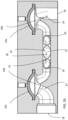
- Figures 2a-2d show views of a fluid distribution device 10 and a fluid distribution manifold 12 according to one embodiment of the invention.
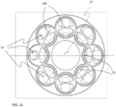
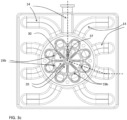
- Figures 3a-3d show different views of a fluid distribution device 110 and a fluid distribution manifold 112 according to another embodiment of the invention.
- Figures 2a and 3a show exploded perspective views of the fluid distribution device 10; 110, Figures 2b and 3b are cross section side views of the fluid distribution manifolds 12; 112 along the dotted lines of Figures 2c and 3c respectively.
- Figures 2c and 3c are top views of the fluid distribution manifolds 12; 112 without membranes provided and
- Figures 2d and 3d are perspective view of the fluid distribution manifolds 12; 112 as mounted.
- the two different embodiments will be described together below and the same reference numbers will be used for corresponding parts in the two different embodiments.
- fluid connection conduits 14 can comprise a membrane 19a and a valve seat 19b or optionally also all fluid conduits except two comprise a membrane 19a and a valve seat 19b. It can also be expressed, as in the claims, that at least three of the fluid connection conduits 14 when there are at least four fluid connection conduits 14 comprise a membrane 19a and a valve seat 19b. Actuation of the membranes 19a into the at least two different positions is provided from membrane actuation members 41 provided in the fluid distribution device 10; 110 as will be further described below.
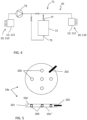
- the membranes 19a may comprise double-layered membranes. As shown in Figure 5 , a membrane 19a can then comprise the two membrane components 19a' and 19a". This mitigates the risk for inappropriate fluid flows in case one membrane component ruptures. Further, the components 19a' and 19a" may be spaced apart by a pattern of spacer elements 200, which can e.g. be studs, pillars, ribs etc. In the space 201 between the components a fluid sensor 202 (e.g. a conductivity sensor, pressure sensor etc.) can then be inserted to detect the presence of fluid due to the rupture of one of the components 19a' and 19a".
- a fluid sensor 202 e.g. a conductivity sensor, pressure sensor etc.
- central common compartment 30 has a form of a sphere or a spheroid which is the case in the embodiment as shown in Figures 2a-2d or is annular as is the case in the embodiment shown in Figures 3a-3d .
- the flow distribution device 10; 110 further comprises at least three membrane actuation members 41 which are provided in connection with one membrane 19a of the flow distribution manifold 12; 112 each.
- one membrane actuation member 41 is provided for each fluid connection conduit 14, i.e. eight membrane actuation members 41 are provided in the flow distribution device 12.
- all fluid connection conduits 14 except one are provided with a membrane actuation member 41.
- Each of said membrane actuation members 41 is configured for actuating the membrane 19a to be in at least two different positions in relation to the valve seat 19b, wherein a first position of the membrane 19a allows flow between the first end 18 and the second end 20 of the fluid connection conduit 14 and a second position of the membrane 19a prevents flow between the first end 18 and the second end 20 of the fluid connection conduit 14.
- the membrane actuation members 41 can be for example pressure controlling members such as tubes through which pressurized air or suction can be provided. Hereby the membranes can be controlled into the at least two different positions by controlling pressure in the membrane actuation members 41.
- Another alternative of membrane actuation members 41 can be some kind of rods in mechanical connection with the membranes whereby a displacement of the rod can be transferred to displacement of the membranes.
- the membranes 19a and valve seats 19b are suitably provided at a position of the fluid connection conduits 14 close to the second ends 20 of the fluid connection conduits 14.
- the distance d1 between the valve seat 19b and the second end 20 of the fluid connection conduit 14 can for example be less than four or less than three or less than two fluid connection tube 14 inner diameters ID.
- the distances between the second ends 20 of each of the fluid connection conduits 14 and a central point 37 of the central common compartment 30 will not differ by more than 3 or 2 or 1 times an inner diameter, ID, of the fluid connection conduits 14.
- the central common compartment 30 is symmetrical and the fluid connection conduits 14 are positioned symmetrical around the central common compartment 30 at substantially the same distance from a central point 37 of the central common compartment 30, i.e. a distance between the second end 20 of each of the fluid connection conduits 14 and a central point 37 of the central common compartment 20 is substantially the same for each fluid connection conduit 14.
- a difference from prior art flow delivery manifolds is that in prior art the fluid connections were provided in parallel while in this new invention at least some of the fluid connection conduits are provided in different directions, i.e. at least some of the fluid connection conduits 14 are spread out from the central common compartment 30.
- a distance from a center of the second end 20 of at least one of the fluid connection conduits 14 to a center of the second end 20 of an adjacent fluid connection conduit 14 is smaller than the distance between central points of two membranes 19a provided to the same two fluid connection conduits 14.
- the flow distribution manifold 12; 112 can be a single-use component. It can be molded from a suitable material, such as for example a polymer, and it can be provided with aseptic connectors for aseptic connection in a system.
- the flow distribution manifold 12; 112 can be pre-sterilized for example by gamma radiation or other sterilization methods, optionally together with other parts of a single-use flow path to be used for example in a bioprocess separation system, such as a chromatography system or a filter system as will be further described below.
- the flow distribution manifold 12; 112 can comprise three parts as disclosed in the exploded views is Figures 2a and 3a .
- a first part 20a comprises the fluid connection conduits 14, the valve seats 19b and the common compartment 30.
- one of the fluid connection conduits 14 has its first end 18 entering towards a side edge 22a of the first part 20a and all the other fluid connection conduits 14 have their first ends 18 entering towards a bottom side 22b of the first part 20a, see Figures 2d and 3d .
- This may be suitable when connecting the fluid distribution device 10; 110 in a system, for example to an inlet or an outlet of a bioprocess separation system as will be further described in relation to Figure 4 below.
- a second part 20b of the flow distribution manifold 12; 112 comprises the membranes 19a and a third part 20c of the flow distribution manifold 12; 112 comprises connections 24 for allowing connection to membrane actuation members 41 and mating them to one membrane 19a each.
- the present invention also relates to a bioprocess separation system 71 as schematically shown in Figure 4 , such as a chromatography system or a filter system, which comprises one or more fluid distribution devices 10; 110 as described above.
- One fluid distribution device 10; 110 can be connected to an inlet 75 of a separation device 73 provided in the bioprocess separation system 71 and/or one fluid distribution device 10; 110 can be connected to an outlet 77 of the separation device 73.
- the separation device 73 can for example be a chromatography column or a filter.
- At least one pump 79 is also provided in the bioprocess separation system 71.
- Other components such as valves and sensors are normally also provided in the bioprocess separation system 71 but will not be described in further detail here.
- a single-use flow path 81 comprising flow paths, the flow distribution manifold 12; 112 according to the invention and optionally also the separation device 73 is also part of the present invention, i.e. the flow distribution manifold 12; 112 can be connected to other flow paths of a bioprocess separation system and be pre-sterilized for easy connection and exchange in a bioprocess separation system 71.
- Reusable parts of the bioprocess separation system 71 are for example pump heads 79 and the membrane actuation members 41 of the flow distribution device 10; 110.
- the central common compartment 30 of the fluid distribution manifold 12; 112 according to the invention can optionally be provided with a sensor, for example an air sensor, pressure sensor or a conductivity sensor.
- a sensor for example an air sensor, pressure sensor or a conductivity sensor.
- the fluid distribution device 10; 110 is compact and flexible. It can be positioned remote from a system where it is used because of the valve control provided by pressurized air.
- the flow distribution manifold is suitable for single-use applications.
- the flow distribution manifold, and optionally a single use flow path to which it can be connected can be pre-sterilized by for example gamma radiation and can be provided with aseptic connectors for aseptic connection in a system.
- the single-use technology is important in the bioprocess industry in order to reduce production cost, increase production throughput and quality and to increase safety.
- wetted parts that are in contact with the process fluid and drug product during processing such as for example fluid storage vessels, tubing, separation equipment etc., are provided as clean and ready to use consumables which are to be installed and used for a specific process, product or over a limited time only and to be disposed thereafter.
- SUT consumables are typically produced, configured and packaged in clean room environments to avoid contamination with microorganisms, particulates etc.
- SUT wetted parts can further be provided clean and pre-sterilized, thus allowing for aseptic and/or sterile processing, hereby reducing above mentioned risks relevant for product, operator or patient safety.
- SUT wetted parts are subjected to a sterilizing gamma irradiation treatment prior to use in the biomanufacturing process, and when doing so they are deployed as 'pre-sterilized' at the point of use.
- SUT single-use technology
- the advantage of using single-use technology (SUT) fluid handling equipment is primarily that cross-contamination in between production batches and campaigns is eliminated when the SUT equipment is used for a single drug product only.
- the SUT equipment is disposed of after use, which can be after a single run, batch or campaign comprising multiple runs and batches.
- initial cleaning and sanitization for example by contacting the flow path with sodium hydroxide solutions
- sterilization can be avoided.
- This enables a LEAN manufacturing approach, because time consuming, costly and non-value adding steps can be omitted.
- cleaning post-use may be omitted.
- the elimination of cleaning procedures and required cleaning fluids further reduces clean water requirements to prepare cleaning solutions in the first place, fluid handling and waste treatment, which translates to reduced facility size and complexity.
- SUT systems provide higher flexibility in (re-)configuring a manufacturing facility and adapting it to different processes and products by design, i.e. through the reduced need for fixed installations compared to traditional processing systems and installations, which for example required auxiliary systems for CIP (Cleaning in Place) and SIP (Sterilization in place).
- CIP Cleaning in Place
- SIP Sterilization in place
- SUT equipment and SUT processing regimes are therefore available or are being made available for the majority of all types of equipment and/or unit operations, among them bioreactors for cell culture or fermentation, buffer bags for liquid storage, tubing and pumps for liquid transfer and filling operations, filters, chromatography columns and related systems for separations.
- SUT equipment does provide improved efficiency, safety and convenience compared to traditional installations and systems.
- Traditional installations and systems for processing are typically made from stainless steel and/or plastic and are not produced under controlled (or clean room) conditions reducing bioburden.
- Traditional systems are typically cleaned in place (CIP), sometimes also sterilized in place (SIP), which not only requires auxiliary installations, equipment and fluids, but involves also substantial time for validation, execution, and quality control of CIP and SIP procedures.
- CIP cleaned in place
- SIP sterilized in place
- the size, cost and complexity of facilities relying on traditional equipment and installations is significantly larger compared to production facilities deploying SUT.
- SUT facilities and processes can be planned, built and started up in significantly shorter time compared to traditional manufacturing technology, and SUT reduces capital investments and financial risk associated with a typically highly dynamic portfolio of drug products as well as risk and uncertainty related to the testing and approval of drug candidates and their product demand.
Landscapes
- Engineering & Computer Science (AREA)
- General Engineering & Computer Science (AREA)
- Health & Medical Sciences (AREA)
- Chemical & Material Sciences (AREA)
- Wood Science & Technology (AREA)
- Bioinformatics & Cheminformatics (AREA)
- Life Sciences & Earth Sciences (AREA)
- Zoology (AREA)
- Organic Chemistry (AREA)
- Mechanical Engineering (AREA)
- Biomedical Technology (AREA)
- Biotechnology (AREA)
- Microbiology (AREA)
- Sustainable Development (AREA)
- Biochemistry (AREA)
- General Health & Medical Sciences (AREA)
- Genetics & Genomics (AREA)
- Clinical Laboratory Science (AREA)
- Analytical Chemistry (AREA)
- Separation Using Semi-Permeable Membranes (AREA)
- Apparatus Associated With Microorganisms And Enzymes (AREA)
- Feeding, Discharge, Calcimining, Fusing, And Gas-Generation Devices (AREA)
- Multiple-Way Valves (AREA)
Claims (15)
- Strömungsverteilungsvorrichtung (10; 110) für Bioprozesssysteme, umfassend:- einen Strömungsverteiler (12; 112), umfassend:▪ mindestens vier Fluidverbindungsleitungen (14), wobei jede Fluidverbindungsleitung (14) ein erstes Ende (18) für eine Fluidverbindung und ein gegenüberliegendes zweites Ende (20) umfasst, und wobei mindestens drei der Fluidverbindungsleitungen eine jeweilige Membran (19a) und einen jeweiligen Ventilsitz (19b) umfassen, wobei die Membranen (19a) so konfiguriert sind, dass sie in mindestens zwei verschiedene Positionen in Bezug auf den jeweiligen Ventilsitz (19b) gebracht werden, um einen Fluidstrom zwischen dem ersten Ende (18) und dem zweiten Ende (20) der Fluidverbindungsleitung (14) zu ermöglichen oder zu verhindern; und▪ ein zentrales gemeinsames Fach (30), mit dem die zweiten Enden (20) jeder der Fluidverbindungsleitungen (14) verbunden sind, wobei die ersten Enden (18) jeder der Fluidverbindungsleitungen (14) in Fluidverbindung mit dem zentralen gemeinsamen Fach (30) stehen, und wobei die Fluidverbindungsleitungen (14) aus mindestens drei verschiedenen Richtungen in das zentrale gemeinsame Fach (30) eintreten;wobei die Strömungsverteilungsvorrichtung (10) weiter umfasst:- mindestens drei Membranbetätigungselemente (41), die in Verbindung mit einer jeweiligen Membran (19a) des Strömungsverteilers (12; 112) bereitgestellt sind, wobei jedes der Membranbetätigungselemente (41) so konfiguriert ist, dass es die jeweilige Membran (19a) so betätigt, dass sie in mindestens zwei verschiedenen Positionen in Bezug auf den jeweiligen Ventilsitz (19b) vorliegt, wobei eine erste Position der jeweiligen Membran (19a) einen Strom zwischen dem ersten Ende (18) und dem zweiten Ende (20) der Fluidverbindungsleitung (14) ermöglicht und eine zweite Position der jeweiligen Membran (19a) einen Strom zwischen dem ersten Ende (18) und dem zweiten Ende (20) der Fluidverbindungsleitung (14) verhindert,wobei die Abstände zwischen den zweiten Enden (20) jeder der Fluidverbindungsleitungen (14) und einem Mittelpunkt (37) des zentralen gemeinsamen Fachs (30) nicht mehr als das 3-, oder 2-, oder 1-fache eines Innendurchmessers (ID) der Fluidverbindungsleitungen (14) voneinander abweichen, oder wobei ein Abstand zwischen dem zweiten Ende (20) jeder der Fluidverbindungsleitungen (14) und einem Mittelpunkt (37) des zentralen gemeinsamen Fachs (30) für jede Fluidverbindungsleitung (14) im Wesentlichen der gleiche ist, undwobei der Strömungsverteiler (12; 112) drei Teile umfasst, wobei ein erster Teil (20a) die Fluidverbindungsleitungen (14), die jeweiligen Ventilsitze (19b) und das zentrale gemeinsame Fach (30) umfasst, wobei ein zweiter Teil (20b) die Membranen (19a) umfasst, und wobei ein dritter Teil (20c) Verbindungen (24) zum Verbinden mit jeweiligen Membranbetätigungselementen (41) umfasst und mit einer jeweiligen Membran (19a) zusammenpasst, dadurch gekennzeichnet, dass das zentrale Fach (30) eine Form einer Kugel oder eines Sphäroids aufweist oder ringförmig ist.
- Strömungsverteilungsvorrichtung (10; 110) nach Anspruch 1, wobei im Strömungsverteiler (12; 112) mindestens fünf oder mindestens sechs Fluidverbindungsleitungen (14) bereitgestellt sind.
- Strömungsverteilungsvorrichtung (10; 110) nach Anspruch 1 oder 2, wobei die Fluidverbindungsleitungen (14) aus mindestens vier oder mindestens fünf verschiedenen Richtungen in das zentrale gemeinsame Fach (30) eintreten.
- Strömungsverteilungsvorrichtung (10; 110) nach einem der vorstehenden Ansprüche, wobei:i) der Fluidverteiler (12) eine sternförmige Konfiguration aufweist, wobei die Fluidverbindungsleitungen (14) vom zentralen gemeinsamen Fach (30) in verschiedene Richtungen weg weisen;ii) das zentrale gemeinsame Fach (30) symmetrisch ist, und die Fluidverbindungsleitungen (14) symmetrisch um das zentrale gemeinsame Fach (30) herum und im Wesentlichen im gleichen Abstand vom Mittelpunkt (37) des zentralen gemeinsamen Fachs (30) positioniert sind;iii) die Strömungsverteilungsvorrichtung (10; 110) aus einem geeigneten Material geformt sein kann und mit aseptischen Anschlüssen bereitgestellt ist; und/oderiv) das zentrale gemeinsame Fach (30) des Fluidverteilers (12; 112) einen Sensor umfasst.
- Strömungsverteilungsvorrichtung (10; 110) nach einem der vorstehenden Ansprüche, wobei die Strömungsverteilungsvorrichtung (10; 110) entweder die gleiche Anzahl von Membranbetätigungselementen (41) wie die Anzahl von im Strömungsverteiler bereitgestellten Fluidverbindungsleitungen (14) oder eine weniger umfasst, wobei in Verbindung mit jeder Fluidverbindungsleitung (14) oder mit jeder Fluidverbindungsleitung (14) außer einer ein Membranbetätigungselement (41) bereitgestellt ist, wobei der Strom entweder durch alle Fluidverbindungsleitungen (14) oder alle bis auf eine durch ein Membranbetätigungselement (41) gesteuert wird.
- Strömungsverteilungsvorrichtung (10; 110) nach einem der vorstehenden Ansprüche, wobei der Strömungsverteiler (12; 112) eine Einwegkomponente ist.
- Strömungsverteilungsvorrichtung (10; 110) nach einem der vorstehenden Ansprüche, wobei die Membranbetätigungselemente (41) Drucksteuerelemente sind.
- Strömungsverteilungsvorrichtung (10; 110) nach einem der vorstehenden Ansprüche, wobei die Membranbetätigungselemente (41) so konfiguriert sind, dass sie durch ein Steuersystem gesteuert werden, wobei die Membranbetätigungselemente (41) gesteuert werden, um die Membranen (19a) zu betätigen, so dass das erste Ende (18) einer der Fluidverbindungsleitungen (14) mit dem ersten Ende (18) einer anderen der Fluidverbindungsleitungen (14) fluidverbunden ist.
- Strömungsverteilungsvorrichtung (10; 110) nach einem der vorstehenden Ansprüche, wobei jede Membran (19a) eine doppelschichtige Membran ist, optional wobei zwei Membrankomponenten davon (19a', 19a") durch ein Muster von Abstandselementen (200) voneinander beabstandet sind, weiter optional wobei ein Raum (201) zwischen den Komponenten (19a', 19a") einen Fluidsensor (202) umfasst, um das Vorhandensein von Fluid aufgrund des Bruchs einer der Komponenten zu erkennen.
- Bioprozess-Trennsystem, umfassend eine Trennvorrichtung (73) und mindestens eine Strömungsverteilungsvorrichtung (10; 110) nach einem der vorstehenden Ansprüche, die mit einem Einlass (75) und/oder einem Auslass (77) der Trennvorrichtung (73) verbunden ist.
- Bioprozess-Trennsystem nach Anspruch 10, wobei die Strömungsverteilungsvorrichtung (10; 110) mit einem Einlass (75) der Trennvorrichtung (73) verbunden ist, wobei eine Fluidverbindungsleitung (14) der Strömungsverteilungsvorrichtung (10; 110) mit dem Einlass (75) der Trennvorrichtung (73) verbunden ist und mindestens drei Fluidverbindungsleitungen (14) der Strömungsverteilungsvorrichtung (10; 110) mit unterschiedlichen Fluidquellen verbunden sind, die Fluide umfassen, die der Trennvorrichtung (73) zugeführt werden sollen.
- Bioprozess-Trennsystem nach Anspruch 10 oder 11, wobei die Strömungsverteilungsvorrichtung (10; 110) mit einem Auslass (77) der Trennvorrichtung (73) verbunden ist, wobei eine Fluidverbindungsleitung (14) der Strömungsverteilungsvorrichtung (10; 110) mit dem Auslass (77) der Trennvorrichtung (73) verbunden ist und mindestens drei Fluidverbindungsleitungen (14) der Strömungsverteilungsvorrichtung (10; 110) mit unterschiedlichen Fraktionssammlern verbunden sind, die unterschiedliche Fraktionen aus der Trennvorrichtung (73) sammeln.
- Bioprozess-Trennsystem nach einem der Ansprüche 10-12, wobei das Bioprozess-Trennsystem (71) umfasst:a) ein wiederverwendbares Teil, das die Membranbetätigungselemente (41) der Strömungsverteilungsvorrichtung (10; 110) und mindestens einen Pumpenkopf umfasst undb) ein Einwegteil, das einen Einwegströmungspfad (81) umfasst, der den Strömungsverteiler (12; 112) der Strömungsverteilungsvorrichtung (10; 110) und optional die Trennvorrichtung (73) umfasst.
- Einweg-Strömungspfad zur Verwendung im Bioprozess-Trennsystem (71) nach einem der Ansprüche 10-13, umfassend eine Strömungsverteilungsvorrichtung (10; 110) nach einem der Ansprüche 1-9.
- Einweg-Strömungspfad nach Anspruch 14, wobei der Einweg-Strömungspfad (81) vorsterilisiert ist.
Applications Claiming Priority (2)
| Application Number | Priority Date | Filing Date | Title |
|---|---|---|---|
| GBGB1820691.2A GB201820691D0 (en) | 2018-12-19 | 2018-12-19 | Device for distributing a flow |
| PCT/EP2019/084322 WO2020126639A1 (en) | 2018-12-19 | 2019-12-10 | Device for distributing a flow |
Publications (2)
| Publication Number | Publication Date |
|---|---|
| EP3897901A1 EP3897901A1 (de) | 2021-10-27 |
| EP3897901B1 true EP3897901B1 (de) | 2025-06-25 |
Family
ID=65147321
Family Applications (1)
| Application Number | Title | Priority Date | Filing Date |
|---|---|---|---|
| EP19817695.0A Active EP3897901B1 (de) | 2018-12-19 | 2019-12-10 | Vorrichtung zur verteilung einer strömung |
Country Status (6)
| Country | Link |
|---|---|
| US (1) | US20220033750A1 (de) |
| EP (1) | EP3897901B1 (de) |
| JP (1) | JP7460247B2 (de) |
| CN (1) | CN113164831A (de) |
| GB (1) | GB201820691D0 (de) |
| WO (1) | WO2020126639A1 (de) |
Families Citing this family (7)
| Publication number | Priority date | Publication date | Assignee | Title |
|---|---|---|---|---|
| GB201820690D0 (en) | 2018-12-19 | 2019-01-30 | Ge Healthcare Bio Sciences Ab | Device for distributing a flow |
| DE102020110209A1 (de) * | 2020-04-14 | 2021-10-14 | Bürkert Werke GmbH & Co. KG | Fluidmodul, Fluidsystem und Verfahren zum Reinigen eines Fluidmoduls |
| CN212455616U (zh) * | 2020-05-27 | 2021-02-02 | 北京科勒有限公司 | 切换阀 |
| DE202020104788U1 (de) * | 2020-08-18 | 2020-11-18 | Sartorius Stedim Biotech Gmbh | Ventilblock zur einmaligen Verwendung in einem Bioprozess |
| CN215257991U (zh) | 2021-05-31 | 2021-12-21 | 南昌科勒有限公司 | 切换阀 |
| EP4098915B1 (de) | 2021-05-31 | 2024-06-12 | Nanchang Kohler Ltd | Schaltventil |
| DE102024117850A1 (de) * | 2024-06-25 | 2026-01-08 | Gemü Gebr. Müller Apparatebau Gmbh & Co. Kommanditgesellschaft | Ventilblockkörper und Armaturanordnung |
Family Cites Families (13)
| Publication number | Priority date | Publication date | Assignee | Title |
|---|---|---|---|---|
| GB2195266B (en) * | 1986-09-17 | 1990-06-20 | Philips Electronic Associated | Liquid chromatograph apparatus including a proportioning arrangement. |
| SE510074C2 (sv) * | 1997-04-04 | 1999-04-19 | Robovalve Ab | Membranventil av flervägstyp |
| JP2008139022A (ja) * | 2005-03-23 | 2008-06-19 | Daicel Chem Ind Ltd | ブロックバルブ及びそれを有する擬似移動床式クロマトグラフィー分離装置 |
| EP1775001A1 (de) * | 2005-10-13 | 2007-04-18 | Xendo Holding B.V. | Vorrichtung für chromatographische Trennungen |
| JP2010209962A (ja) * | 2009-03-09 | 2010-09-24 | Nippon Soken Inc | 流体切替弁 |
| US10094481B2 (en) * | 2012-03-30 | 2018-10-09 | Ge Healthcare Bio-Sciences Ab | Device for delivery of sample fluid |
| DE102013020585A1 (de) * | 2013-12-13 | 2015-06-18 | Hydac Fluidtechnik Gmbh | Ventilvorrichtung |
| DE102014226692A1 (de) * | 2014-12-19 | 2016-06-23 | Hamilton Bonaduz Ag | Fluid-Versorgungsschnittstelle, insbesondere zur Versorgung von Zellkulturbehältern, mit wechselnd zur Fluidleitung anschließbaren Fluidkanälen |
| CN107106929B (zh) * | 2014-12-31 | 2020-06-09 | 通用电气健康护理生物科学股份公司 | 用于模拟移动床层析的阀歧管 |
| CN106499841B (zh) * | 2016-12-14 | 2019-02-01 | 广州中国科学院先进技术研究所 | 一种改进的小型化膜阀 |
| WO2018172811A1 (en) * | 2017-03-20 | 2018-09-27 | Sartorius Stedim North America Inc. | A fluid transfer assembly, a fluid transfer system, and a related method |
| CN108757995B (zh) * | 2018-07-24 | 2023-07-28 | 凯铭科技(杭州)有限公司 | 一种多通道流控阀 |
| GB201820690D0 (en) * | 2018-12-19 | 2019-01-30 | Ge Healthcare Bio Sciences Ab | Device for distributing a flow |
-
2018
- 2018-12-19 GB GBGB1820691.2A patent/GB201820691D0/en not_active Ceased
-
2019
- 2019-12-10 EP EP19817695.0A patent/EP3897901B1/de active Active
- 2019-12-10 US US17/296,726 patent/US20220033750A1/en active Pending
- 2019-12-10 CN CN201980084491.3A patent/CN113164831A/zh active Pending
- 2019-12-10 WO PCT/EP2019/084322 patent/WO2020126639A1/en not_active Ceased
- 2019-12-10 JP JP2021534143A patent/JP7460247B2/ja active Active
Also Published As
| Publication number | Publication date |
|---|---|
| GB201820691D0 (en) | 2019-01-30 |
| CN113164831A (zh) | 2021-07-23 |
| WO2020126639A1 (en) | 2020-06-25 |
| JP2022514247A (ja) | 2022-02-10 |
| US20220033750A1 (en) | 2022-02-03 |
| EP3897901A1 (de) | 2021-10-27 |
| JP7460247B2 (ja) | 2024-04-02 |
Similar Documents
| Publication | Publication Date | Title |
|---|---|---|
| US20220033750A1 (en) | Device for Distributing a Flow | |
| US12264306B2 (en) | Device for distributing a flow | |
| US12140235B2 (en) | Valve block for single use in a bio process | |
| EP3241021A1 (de) | Ventilinseln für simulierte fliessbettchromatografie | |
| EP3391042B1 (de) | Stapelbare chromatographiesäulenmodule mit ein- und auslassventilen | |
| KR20220117279A (ko) | 바이오프로세싱 디바이스 | |
| US20250339856A1 (en) | System and Method for a Pharmaceutical Product | |
| US10208277B2 (en) | Flow-path control method, and cell culture device | |
| US20210387189A1 (en) | A Bioprocessing Fluid Sensor Arrangement | |
| CN219168137U (zh) | 用于生物大分子物质产品的生产设备 | |
| CN104353282A (zh) | 灌装密闭系统无菌过滤设备 | |
| CN111111484A (zh) | 一种协同连续pH灭活液混合系统及其应用 | |
| US12616918B2 (en) | Connection device for a separation system such as a chromatography system | |
| CN115715319A (zh) | 生物制药工艺用智能罐 | |
| EP3824209B1 (de) | Ventil für eine bioprozessflüssigkeit | |
| CN220556060U (zh) | 一次性小管径阀门 | |
| CN115920639A (zh) | 用于生物大分子物质产品的生产设备 | |
| Jornitz | The Review of Flexible Production Platforms for the Future | |
| WO2023188937A1 (ja) | バイオ医薬品の原薬の製造方法、バイオ医薬品の原薬の製造システム、およびバイオ医薬品の原薬 |
Legal Events
| Date | Code | Title | Description |
|---|---|---|---|
| STAA | Information on the status of an ep patent application or granted ep patent |
Free format text: STATUS: UNKNOWN |
|
| STAA | Information on the status of an ep patent application or granted ep patent |
Free format text: STATUS: THE INTERNATIONAL PUBLICATION HAS BEEN MADE |
|
| PUAI | Public reference made under article 153(3) epc to a published international application that has entered the european phase |
Free format text: ORIGINAL CODE: 0009012 |
|
| STAA | Information on the status of an ep patent application or granted ep patent |
Free format text: STATUS: REQUEST FOR EXAMINATION WAS MADE |
|
| 17P | Request for examination filed |
Effective date: 20210519 |
|
| AK | Designated contracting states |
Kind code of ref document: A1 Designated state(s): AL AT BE BG CH CY CZ DE DK EE ES FI FR GB GR HR HU IE IS IT LI LT LU LV MC MK MT NL NO PL PT RO RS SE SI SK SM TR |
|
| DAV | Request for validation of the european patent (deleted) | ||
| DAX | Request for extension of the european patent (deleted) | ||
| STAA | Information on the status of an ep patent application or granted ep patent |
Free format text: STATUS: EXAMINATION IS IN PROGRESS |
|
| 17Q | First examination report despatched |
Effective date: 20230601 |
|
| P01 | Opt-out of the competence of the unified patent court (upc) registered |
Effective date: 20230526 |
|
| GRAP | Despatch of communication of intention to grant a patent |
Free format text: ORIGINAL CODE: EPIDOSNIGR1 |
|
| STAA | Information on the status of an ep patent application or granted ep patent |
Free format text: STATUS: GRANT OF PATENT IS INTENDED |
|
| RIC1 | Information provided on ipc code assigned before grant |
Ipc: F16K 31/126 20060101ALI20250404BHEP Ipc: G01N 30/00 20060101ALI20250404BHEP Ipc: F16K 27/02 20060101ALI20250404BHEP Ipc: F16K 11/22 20060101ALI20250404BHEP Ipc: F16K 11/02 20060101ALI20250404BHEP Ipc: F16K 7/12 20060101ALI20250404BHEP Ipc: B01D 15/08 20060101AFI20250404BHEP |
|
| GRAS | Grant fee paid |
Free format text: ORIGINAL CODE: EPIDOSNIGR3 |
|
| INTG | Intention to grant announced |
Effective date: 20250416 |
|
| GRAA | (expected) grant |
Free format text: ORIGINAL CODE: 0009210 |
|
| STAA | Information on the status of an ep patent application or granted ep patent |
Free format text: STATUS: THE PATENT HAS BEEN GRANTED |
|
| AK | Designated contracting states |
Kind code of ref document: B1 Designated state(s): AL AT BE BG CH CY CZ DE DK EE ES FI FR GB GR HR HU IE IS IT LI LT LU LV MC MK MT NL NO PL PT RO RS SE SI SK SM TR |
|
| REG | Reference to a national code |
Ref country code: GB Ref legal event code: FG4D |
|
| REG | Reference to a national code |
Ref country code: CH Ref legal event code: EP |
|
| REG | Reference to a national code |
Ref country code: DE Ref legal event code: R096 Ref document number: 602019071658 Country of ref document: DE |
|
| REG | Reference to a national code |
Ref country code: CH Ref legal event code: EP |
|
| REG | Reference to a national code |
Ref country code: IE Ref legal event code: FG4D |
|
| PG25 | Lapsed in a contracting state [announced via postgrant information from national office to epo] |
Ref country code: FI Free format text: LAPSE BECAUSE OF FAILURE TO SUBMIT A TRANSLATION OF THE DESCRIPTION OR TO PAY THE FEE WITHIN THE PRESCRIBED TIME-LIMIT Effective date: 20250625 |
|
| REG | Reference to a national code |
Ref country code: LT Ref legal event code: MG9D |
|
| PG25 | Lapsed in a contracting state [announced via postgrant information from national office to epo] |
Ref country code: NO Free format text: LAPSE BECAUSE OF FAILURE TO SUBMIT A TRANSLATION OF THE DESCRIPTION OR TO PAY THE FEE WITHIN THE PRESCRIBED TIME-LIMIT Effective date: 20250925 Ref country code: GR Free format text: LAPSE BECAUSE OF FAILURE TO SUBMIT A TRANSLATION OF THE DESCRIPTION OR TO PAY THE FEE WITHIN THE PRESCRIBED TIME-LIMIT Effective date: 20250926 |
|
| PG25 | Lapsed in a contracting state [announced via postgrant information from national office to epo] |
Ref country code: BG Free format text: LAPSE BECAUSE OF FAILURE TO SUBMIT A TRANSLATION OF THE DESCRIPTION OR TO PAY THE FEE WITHIN THE PRESCRIBED TIME-LIMIT Effective date: 20250625 |
|
| PG25 | Lapsed in a contracting state [announced via postgrant information from national office to epo] |
Ref country code: HR Free format text: LAPSE BECAUSE OF FAILURE TO SUBMIT A TRANSLATION OF THE DESCRIPTION OR TO PAY THE FEE WITHIN THE PRESCRIBED TIME-LIMIT Effective date: 20250625 |
|
| PG25 | Lapsed in a contracting state [announced via postgrant information from national office to epo] |
Ref country code: RS Free format text: LAPSE BECAUSE OF FAILURE TO SUBMIT A TRANSLATION OF THE DESCRIPTION OR TO PAY THE FEE WITHIN THE PRESCRIBED TIME-LIMIT Effective date: 20250925 |
|
| PG25 | Lapsed in a contracting state [announced via postgrant information from national office to epo] |
Ref country code: LV Free format text: LAPSE BECAUSE OF FAILURE TO SUBMIT A TRANSLATION OF THE DESCRIPTION OR TO PAY THE FEE WITHIN THE PRESCRIBED TIME-LIMIT Effective date: 20250625 |
|
| REG | Reference to a national code |
Ref country code: NL Ref legal event code: MP Effective date: 20250625 |
|
| PG25 | Lapsed in a contracting state [announced via postgrant information from national office to epo] |
Ref country code: NL Free format text: LAPSE BECAUSE OF FAILURE TO SUBMIT A TRANSLATION OF THE DESCRIPTION OR TO PAY THE FEE WITHIN THE PRESCRIBED TIME-LIMIT Effective date: 20250625 |
|
| PG25 | Lapsed in a contracting state [announced via postgrant information from national office to epo] |
Ref country code: PT Free format text: LAPSE BECAUSE OF FAILURE TO SUBMIT A TRANSLATION OF THE DESCRIPTION OR TO PAY THE FEE WITHIN THE PRESCRIBED TIME-LIMIT Effective date: 20251027 |
|
| REG | Reference to a national code |
Ref country code: AT Ref legal event code: MK05 Ref document number: 1805900 Country of ref document: AT Kind code of ref document: T Effective date: 20250625 |
|
| PG25 | Lapsed in a contracting state [announced via postgrant information from national office to epo] |
Ref country code: IS Free format text: LAPSE BECAUSE OF FAILURE TO SUBMIT A TRANSLATION OF THE DESCRIPTION OR TO PAY THE FEE WITHIN THE PRESCRIBED TIME-LIMIT Effective date: 20251025 |
|
| PGFP | Annual fee paid to national office [announced via postgrant information from national office to epo] |
Ref country code: GB Payment date: 20251223 Year of fee payment: 7 |
|
| PG25 | Lapsed in a contracting state [announced via postgrant information from national office to epo] |
Ref country code: AT Free format text: LAPSE BECAUSE OF FAILURE TO SUBMIT A TRANSLATION OF THE DESCRIPTION OR TO PAY THE FEE WITHIN THE PRESCRIBED TIME-LIMIT Effective date: 20250625 Ref country code: SM Free format text: LAPSE BECAUSE OF FAILURE TO SUBMIT A TRANSLATION OF THE DESCRIPTION OR TO PAY THE FEE WITHIN THE PRESCRIBED TIME-LIMIT Effective date: 20250625 |
|
| PGFP | Annual fee paid to national office [announced via postgrant information from national office to epo] |
Ref country code: FR Payment date: 20251230 Year of fee payment: 7 |
|
| PG25 | Lapsed in a contracting state [announced via postgrant information from national office to epo] |
Ref country code: CZ Free format text: LAPSE BECAUSE OF FAILURE TO SUBMIT A TRANSLATION OF THE DESCRIPTION OR TO PAY THE FEE WITHIN THE PRESCRIBED TIME-LIMIT Effective date: 20250625 |
|
| PG25 | Lapsed in a contracting state [announced via postgrant information from national office to epo] |
Ref country code: PL Free format text: LAPSE BECAUSE OF FAILURE TO SUBMIT A TRANSLATION OF THE DESCRIPTION OR TO PAY THE FEE WITHIN THE PRESCRIBED TIME-LIMIT Effective date: 20250625 |
|
| PG25 | Lapsed in a contracting state [announced via postgrant information from national office to epo] |
Ref country code: EE Free format text: LAPSE BECAUSE OF FAILURE TO SUBMIT A TRANSLATION OF THE DESCRIPTION OR TO PAY THE FEE WITHIN THE PRESCRIBED TIME-LIMIT Effective date: 20250625 |
|
| PG25 | Lapsed in a contracting state [announced via postgrant information from national office to epo] |
Ref country code: SK Free format text: LAPSE BECAUSE OF FAILURE TO SUBMIT A TRANSLATION OF THE DESCRIPTION OR TO PAY THE FEE WITHIN THE PRESCRIBED TIME-LIMIT Effective date: 20250625 |
|
| PG25 | Lapsed in a contracting state [announced via postgrant information from national office to epo] |
Ref country code: ES Free format text: LAPSE BECAUSE OF FAILURE TO SUBMIT A TRANSLATION OF THE DESCRIPTION OR TO PAY THE FEE WITHIN THE PRESCRIBED TIME-LIMIT Effective date: 20250625 |
|
| PG25 | Lapsed in a contracting state [announced via postgrant information from national office to epo] |
Ref country code: RO Free format text: LAPSE BECAUSE OF FAILURE TO SUBMIT A TRANSLATION OF THE DESCRIPTION OR TO PAY THE FEE WITHIN THE PRESCRIBED TIME-LIMIT Effective date: 20250625 |
|
| PG25 | Lapsed in a contracting state [announced via postgrant information from national office to epo] |
Ref country code: DK Free format text: LAPSE BECAUSE OF FAILURE TO SUBMIT A TRANSLATION OF THE DESCRIPTION OR TO PAY THE FEE WITHIN THE PRESCRIBED TIME-LIMIT Effective date: 20250625 |
|
| PGFP | Annual fee paid to national office [announced via postgrant information from national office to epo] |
Ref country code: DE Payment date: 20251229 Year of fee payment: 7 |
|
| PG25 | Lapsed in a contracting state [announced via postgrant information from national office to epo] |
Ref country code: IT Free format text: LAPSE BECAUSE OF FAILURE TO SUBMIT A TRANSLATION OF THE DESCRIPTION OR TO PAY THE FEE WITHIN THE PRESCRIBED TIME-LIMIT Effective date: 20250625 |
|
| PLBE | No opposition filed within time limit |
Free format text: ORIGINAL CODE: 0009261 |
|
| STAA | Information on the status of an ep patent application or granted ep patent |
Free format text: STATUS: NO OPPOSITION FILED WITHIN TIME LIMIT |
|
| REG | Reference to a national code |
Ref country code: CH Ref legal event code: L10 Free format text: ST27 STATUS EVENT CODE: U-0-0-L10-L00 (AS PROVIDED BY THE NATIONAL OFFICE) Effective date: 20260507 |