EP3897371B1 - Implantierbare medizinische vorrichtung mit verstellbarem blutfluss - Google Patents
Implantierbare medizinische vorrichtung mit verstellbarem blutfluss Download PDFInfo
- Publication number
- EP3897371B1 EP3897371B1 EP19842528.2A EP19842528A EP3897371B1 EP 3897371 B1 EP3897371 B1 EP 3897371B1 EP 19842528 A EP19842528 A EP 19842528A EP 3897371 B1 EP3897371 B1 EP 3897371B1
- Authority
- EP
- European Patent Office
- Prior art keywords
- medical device
- implantable medical
- cover
- fluid shunt
- lumen
- Prior art date
- Legal status (The legal status is an assumption and is not a legal conclusion. Google has not performed a legal analysis and makes no representation as to the accuracy of the status listed.)
- Active
Links
Images






Classifications
-
- A—HUMAN NECESSITIES
- A61—MEDICAL OR VETERINARY SCIENCE; HYGIENE
- A61B—DIAGNOSIS; SURGERY; IDENTIFICATION
- A61B5/00—Measuring for diagnostic purposes; Identification of persons
- A61B5/02—Detecting, measuring or recording for evaluating the cardiovascular system, e.g. pulse, heart rate, blood pressure or blood flow
- A61B5/0205—Simultaneously evaluating both cardiovascular conditions and different types of body conditions, e.g. heart and respiratory condition
- A61B5/02055—Simultaneously evaluating both cardiovascular condition and temperature
-
- A—HUMAN NECESSITIES
- A61—MEDICAL OR VETERINARY SCIENCE; HYGIENE
- A61B—DIAGNOSIS; SURGERY; IDENTIFICATION
- A61B5/00—Measuring for diagnostic purposes; Identification of persons
- A61B5/0002—Remote monitoring of patients using telemetry, e.g. transmission of vital signals via a communication network
- A61B5/0031—Implanted circuitry
-
- A—HUMAN NECESSITIES
- A61—MEDICAL OR VETERINARY SCIENCE; HYGIENE
- A61B—DIAGNOSIS; SURGERY; IDENTIFICATION
- A61B5/00—Measuring for diagnostic purposes; Identification of persons
- A61B5/02—Detecting, measuring or recording for evaluating the cardiovascular system, e.g. pulse, heart rate, blood pressure or blood flow
- A61B5/0205—Simultaneously evaluating both cardiovascular conditions and different types of body conditions, e.g. heart and respiratory condition
-
- A—HUMAN NECESSITIES
- A61—MEDICAL OR VETERINARY SCIENCE; HYGIENE
- A61B—DIAGNOSIS; SURGERY; IDENTIFICATION
- A61B5/00—Measuring for diagnostic purposes; Identification of persons
- A61B5/02—Detecting, measuring or recording for evaluating the cardiovascular system, e.g. pulse, heart rate, blood pressure or blood flow
- A61B5/021—Measuring pressure in heart or blood vessels
-
- A—HUMAN NECESSITIES
- A61—MEDICAL OR VETERINARY SCIENCE; HYGIENE
- A61B—DIAGNOSIS; SURGERY; IDENTIFICATION
- A61B5/00—Measuring for diagnostic purposes; Identification of persons
- A61B5/07—Endoradiosondes
- A61B5/076—Permanent implantation
-
- A—HUMAN NECESSITIES
- A61—MEDICAL OR VETERINARY SCIENCE; HYGIENE
- A61B—DIAGNOSIS; SURGERY; IDENTIFICATION
- A61B5/00—Measuring for diagnostic purposes; Identification of persons
- A61B5/145—Measuring characteristics of blood in vivo, e.g. gas concentration or pH-value ; Measuring characteristics of body fluids or tissues, e.g. interstitial fluid or cerebral tissue
- A61B5/14542—Measuring characteristics of blood in vivo, e.g. gas concentration or pH-value ; Measuring characteristics of body fluids or tissues, e.g. interstitial fluid or cerebral tissue for measuring blood gases
-
- A—HUMAN NECESSITIES
- A61—MEDICAL OR VETERINARY SCIENCE; HYGIENE
- A61B—DIAGNOSIS; SURGERY; IDENTIFICATION
- A61B5/00—Measuring for diagnostic purposes; Identification of persons
- A61B5/145—Measuring characteristics of blood in vivo, e.g. gas concentration or pH-value ; Measuring characteristics of body fluids or tissues, e.g. interstitial fluid or cerebral tissue
- A61B5/1455—Measuring characteristics of blood in vivo, e.g. gas concentration or pH-value ; Measuring characteristics of body fluids or tissues, e.g. interstitial fluid or cerebral tissue using optical sensors, e.g. spectral photometrical oximeters
- A61B5/14551—Measuring characteristics of blood in vivo, e.g. gas concentration or pH-value ; Measuring characteristics of body fluids or tissues, e.g. interstitial fluid or cerebral tissue using optical sensors, e.g. spectral photometrical oximeters for measuring blood gases
- A61B5/14552—Details of sensors specially adapted therefor
-
- A—HUMAN NECESSITIES
- A61—MEDICAL OR VETERINARY SCIENCE; HYGIENE
- A61B—DIAGNOSIS; SURGERY; IDENTIFICATION
- A61B5/00—Measuring for diagnostic purposes; Identification of persons
- A61B5/20—Measuring for diagnostic purposes; Identification of persons for measuring urological functions restricted to the evaluation of the urinary system
- A61B5/201—Assessing renal or kidney functions
-
- A—HUMAN NECESSITIES
- A61—MEDICAL OR VETERINARY SCIENCE; HYGIENE
- A61B—DIAGNOSIS; SURGERY; IDENTIFICATION
- A61B5/00—Measuring for diagnostic purposes; Identification of persons
- A61B5/48—Other medical applications
- A61B5/4836—Diagnosis combined with treatment in closed-loop systems or methods
- A61B5/4839—Diagnosis combined with treatment in closed-loop systems or methods combined with drug delivery
-
- A—HUMAN NECESSITIES
- A61—MEDICAL OR VETERINARY SCIENCE; HYGIENE
- A61B—DIAGNOSIS; SURGERY; IDENTIFICATION
- A61B5/00—Measuring for diagnostic purposes; Identification of persons
- A61B5/48—Other medical applications
- A61B5/486—Biofeedback
-
- A—HUMAN NECESSITIES
- A61—MEDICAL OR VETERINARY SCIENCE; HYGIENE
- A61B—DIAGNOSIS; SURGERY; IDENTIFICATION
- A61B5/00—Measuring for diagnostic purposes; Identification of persons
- A61B5/68—Arrangements of detecting, measuring or recording means, e.g. sensors, in relation to patient
- A61B5/6846—Arrangements of detecting, measuring or recording means, e.g. sensors, in relation to patient specially adapted to be brought in contact with an internal body part, i.e. invasive
- A61B5/6847—Arrangements of detecting, measuring or recording means, e.g. sensors, in relation to patient specially adapted to be brought in contact with an internal body part, i.e. invasive mounted on an invasive device
-
- A—HUMAN NECESSITIES
- A61—MEDICAL OR VETERINARY SCIENCE; HYGIENE
- A61B—DIAGNOSIS; SURGERY; IDENTIFICATION
- A61B5/00—Measuring for diagnostic purposes; Identification of persons
- A61B5/68—Arrangements of detecting, measuring or recording means, e.g. sensors, in relation to patient
- A61B5/6846—Arrangements of detecting, measuring or recording means, e.g. sensors, in relation to patient specially adapted to be brought in contact with an internal body part, i.e. invasive
- A61B5/6867—Arrangements of detecting, measuring or recording means, e.g. sensors, in relation to patient specially adapted to be brought in contact with an internal body part, i.e. invasive specially adapted to be attached or implanted in a specific body part
- A61B5/6869—Heart
-
- A—HUMAN NECESSITIES
- A61—MEDICAL OR VETERINARY SCIENCE; HYGIENE
- A61B—DIAGNOSIS; SURGERY; IDENTIFICATION
- A61B5/00—Measuring for diagnostic purposes; Identification of persons
- A61B5/68—Arrangements of detecting, measuring or recording means, e.g. sensors, in relation to patient
- A61B5/6846—Arrangements of detecting, measuring or recording means, e.g. sensors, in relation to patient specially adapted to be brought in contact with an internal body part, i.e. invasive
- A61B5/6879—Means for maintaining contact with the body
- A61B5/6882—Anchoring means
-
- A—HUMAN NECESSITIES
- A61—MEDICAL OR VETERINARY SCIENCE; HYGIENE
- A61B—DIAGNOSIS; SURGERY; IDENTIFICATION
- A61B5/00—Measuring for diagnostic purposes; Identification of persons
- A61B5/72—Signal processing specially adapted for physiological signals or for diagnostic purposes
- A61B5/7271—Specific aspects of physiological measurement analysis
- A61B5/7275—Determining trends in physiological measurement data; Predicting development of a medical condition based on physiological measurements, e.g. determining a risk factor
-
- A—HUMAN NECESSITIES
- A61—MEDICAL OR VETERINARY SCIENCE; HYGIENE
- A61B—DIAGNOSIS; SURGERY; IDENTIFICATION
- A61B5/00—Measuring for diagnostic purposes; Identification of persons
- A61B5/74—Details of notification to user or communication with user or patient; User input means
- A61B5/742—Details of notification to user or communication with user or patient; User input means using visual displays
-
- A—HUMAN NECESSITIES
- A61—MEDICAL OR VETERINARY SCIENCE; HYGIENE
- A61F—FILTERS IMPLANTABLE INTO BLOOD VESSELS; PROSTHESES; DEVICES PROVIDING PATENCY TO, OR PREVENTING COLLAPSING OF, TUBULAR STRUCTURES OF THE BODY, e.g. STENTS; ORTHOPAEDIC, NURSING OR CONTRACEPTIVE DEVICES; FOMENTATION; TREATMENT OR PROTECTION OF EYES OR EARS; BANDAGES, DRESSINGS OR ABSORBENT PADS; FIRST-AID KITS
- A61F2/00—Filters implantable into blood vessels; Prostheses, i.e. artificial substitutes or replacements for parts of the body; Appliances for connecting them with the body; Devices providing patency to, or preventing collapsing of, tubular structures of the body, e.g. stents
- A61F2/02—Prostheses implantable into the body
- A61F2/24—Heart valves ; Vascular valves, e.g. venous valves; Heart implants, e.g. passive devices for improving the function of the native valve or the heart muscle; Transmyocardial revascularisation [TMR] devices; Valves implantable in the body
- A61F2/2478—Passive devices for improving the function of the heart muscle, i.e. devices for reshaping the external surface of the heart, e.g. bags, strips or bands
- A61F2/2487—Devices within the heart chamber, e.g. splints
-
- A—HUMAN NECESSITIES
- A61—MEDICAL OR VETERINARY SCIENCE; HYGIENE
- A61L—METHODS OR APPARATUS FOR STERILISING MATERIALS OR OBJECTS IN GENERAL; DISINFECTION, STERILISATION OR DEODORISATION OF AIR; CHEMICAL ASPECTS OF BANDAGES, DRESSINGS, ABSORBENT PADS OR SURGICAL ARTICLES; MATERIALS FOR BANDAGES, DRESSINGS, ABSORBENT PADS OR SURGICAL ARTICLES
- A61L31/00—Materials for other surgical articles, e.g. stents, stent-grafts, shunts, surgical drapes, guide wires, materials for adhesion prevention, occluding devices, surgical gloves, tissue fixation devices
- A61L31/08—Materials for coatings
- A61L31/10—Macromolecular materials
-
- A—HUMAN NECESSITIES
- A61—MEDICAL OR VETERINARY SCIENCE; HYGIENE
- A61M—DEVICES FOR INTRODUCING MEDIA INTO, OR ONTO, THE BODY; DEVICES FOR TRANSDUCING BODY MEDIA OR FOR TAKING MEDIA FROM THE BODY; DEVICES FOR PRODUCING OR ENDING SLEEP OR STUPOR
- A61M27/00—Drainage appliance for wounds or the like, i.e. wound drains, implanted drains
- A61M27/002—Implant devices for drainage of body fluids from one part of the body to another
-
- A—HUMAN NECESSITIES
- A61—MEDICAL OR VETERINARY SCIENCE; HYGIENE
- A61B—DIAGNOSIS; SURGERY; IDENTIFICATION
- A61B17/00—Surgical instruments, devices or methods
- A61B17/12—Surgical instruments, devices or methods for ligaturing or otherwise compressing tubular parts of the body, e.g. blood vessels or umbilical cord
- A61B17/12022—Occluding by internal devices, e.g. balloons or releasable wires
-
- A—HUMAN NECESSITIES
- A61—MEDICAL OR VETERINARY SCIENCE; HYGIENE
- A61B—DIAGNOSIS; SURGERY; IDENTIFICATION
- A61B2560/00—Constructional details of operational features of apparatus; Accessories for medical measuring apparatus
- A61B2560/02—Operational features
- A61B2560/0204—Operational features of power management
- A61B2560/0214—Operational features of power management of power generation or supply
- A61B2560/0219—Operational features of power management of power generation or supply of externally powered implanted units
-
- A—HUMAN NECESSITIES
- A61—MEDICAL OR VETERINARY SCIENCE; HYGIENE
- A61B—DIAGNOSIS; SURGERY; IDENTIFICATION
- A61B5/00—Measuring for diagnostic purposes; Identification of persons
- A61B5/02—Detecting, measuring or recording for evaluating the cardiovascular system, e.g. pulse, heart rate, blood pressure or blood flow
- A61B5/021—Measuring pressure in heart or blood vessels
- A61B5/0215—Measuring pressure in heart or blood vessels by means inserted into the body
-
- A—HUMAN NECESSITIES
- A61—MEDICAL OR VETERINARY SCIENCE; HYGIENE
- A61B—DIAGNOSIS; SURGERY; IDENTIFICATION
- A61B5/00—Measuring for diagnostic purposes; Identification of persons
- A61B5/02—Detecting, measuring or recording for evaluating the cardiovascular system, e.g. pulse, heart rate, blood pressure or blood flow
- A61B5/021—Measuring pressure in heart or blood vessels
- A61B5/0215—Measuring pressure in heart or blood vessels by means inserted into the body
- A61B5/02158—Measuring pressure in heart or blood vessels by means inserted into the body provided with two or more sensor elements
-
- A—HUMAN NECESSITIES
- A61—MEDICAL OR VETERINARY SCIENCE; HYGIENE
- A61F—FILTERS IMPLANTABLE INTO BLOOD VESSELS; PROSTHESES; DEVICES PROVIDING PATENCY TO, OR PREVENTING COLLAPSING OF, TUBULAR STRUCTURES OF THE BODY, e.g. STENTS; ORTHOPAEDIC, NURSING OR CONTRACEPTIVE DEVICES; FOMENTATION; TREATMENT OR PROTECTION OF EYES OR EARS; BANDAGES, DRESSINGS OR ABSORBENT PADS; FIRST-AID KITS
- A61F2250/00—Special features of prostheses classified in groups A61F2/00 - A61F2/26 or A61F2/82 or A61F9/00 or A61F11/00 or subgroups thereof
- A61F2250/0001—Means for transferring electromagnetic energy to implants
-
- A—HUMAN NECESSITIES
- A61—MEDICAL OR VETERINARY SCIENCE; HYGIENE
- A61F—FILTERS IMPLANTABLE INTO BLOOD VESSELS; PROSTHESES; DEVICES PROVIDING PATENCY TO, OR PREVENTING COLLAPSING OF, TUBULAR STRUCTURES OF THE BODY, e.g. STENTS; ORTHOPAEDIC, NURSING OR CONTRACEPTIVE DEVICES; FOMENTATION; TREATMENT OR PROTECTION OF EYES OR EARS; BANDAGES, DRESSINGS OR ABSORBENT PADS; FIRST-AID KITS
- A61F2250/00—Special features of prostheses classified in groups A61F2/00 - A61F2/26 or A61F2/82 or A61F9/00 or A61F11/00 or subgroups thereof
- A61F2250/0001—Means for transferring electromagnetic energy to implants
- A61F2250/0002—Means for transferring electromagnetic energy to implants for data transfer
-
- A—HUMAN NECESSITIES
- A61—MEDICAL OR VETERINARY SCIENCE; HYGIENE
- A61F—FILTERS IMPLANTABLE INTO BLOOD VESSELS; PROSTHESES; DEVICES PROVIDING PATENCY TO, OR PREVENTING COLLAPSING OF, TUBULAR STRUCTURES OF THE BODY, e.g. STENTS; ORTHOPAEDIC, NURSING OR CONTRACEPTIVE DEVICES; FOMENTATION; TREATMENT OR PROTECTION OF EYES OR EARS; BANDAGES, DRESSINGS OR ABSORBENT PADS; FIRST-AID KITS
- A61F2250/00—Special features of prostheses classified in groups A61F2/00 - A61F2/26 or A61F2/82 or A61F9/00 or A61F11/00 or subgroups thereof
- A61F2250/0058—Additional features; Implant or prostheses properties not otherwise provided for
- A61F2250/0069—Sealing means
-
- A—HUMAN NECESSITIES
- A61—MEDICAL OR VETERINARY SCIENCE; HYGIENE
- A61F—FILTERS IMPLANTABLE INTO BLOOD VESSELS; PROSTHESES; DEVICES PROVIDING PATENCY TO, OR PREVENTING COLLAPSING OF, TUBULAR STRUCTURES OF THE BODY, e.g. STENTS; ORTHOPAEDIC, NURSING OR CONTRACEPTIVE DEVICES; FOMENTATION; TREATMENT OR PROTECTION OF EYES OR EARS; BANDAGES, DRESSINGS OR ABSORBENT PADS; FIRST-AID KITS
- A61F2250/00—Special features of prostheses classified in groups A61F2/00 - A61F2/26 or A61F2/82 or A61F9/00 or A61F11/00 or subgroups thereof
- A61F2250/0058—Additional features; Implant or prostheses properties not otherwise provided for
- A61F2250/0093—Ultrasound system, e.g. for inducing coagulation during eye surgery
-
- A—HUMAN NECESSITIES
- A61—MEDICAL OR VETERINARY SCIENCE; HYGIENE
- A61L—METHODS OR APPARATUS FOR STERILISING MATERIALS OR OBJECTS IN GENERAL; DISINFECTION, STERILISATION OR DEODORISATION OF AIR; CHEMICAL ASPECTS OF BANDAGES, DRESSINGS, ABSORBENT PADS OR SURGICAL ARTICLES; MATERIALS FOR BANDAGES, DRESSINGS, ABSORBENT PADS OR SURGICAL ARTICLES
- A61L2300/00—Biologically active materials used in bandages, wound dressings, absorbent pads or medical devices
- A61L2300/20—Biologically active materials used in bandages, wound dressings, absorbent pads or medical devices containing or releasing organic materials
- A61L2300/23—Carbohydrates
- A61L2300/236—Glycosaminoglycans, e.g. heparin, hyaluronic acid, chondroitin
-
- A—HUMAN NECESSITIES
- A61—MEDICAL OR VETERINARY SCIENCE; HYGIENE
- A61L—METHODS OR APPARATUS FOR STERILISING MATERIALS OR OBJECTS IN GENERAL; DISINFECTION, STERILISATION OR DEODORISATION OF AIR; CHEMICAL ASPECTS OF BANDAGES, DRESSINGS, ABSORBENT PADS OR SURGICAL ARTICLES; MATERIALS FOR BANDAGES, DRESSINGS, ABSORBENT PADS OR SURGICAL ARTICLES
- A61L2300/00—Biologically active materials used in bandages, wound dressings, absorbent pads or medical devices
- A61L2300/40—Biologically active materials used in bandages, wound dressings, absorbent pads or medical devices characterised by a specific therapeutic activity or mode of action
- A61L2300/42—Anti-thrombotic agents, anticoagulants, anti-platelet agents
-
- A—HUMAN NECESSITIES
- A61—MEDICAL OR VETERINARY SCIENCE; HYGIENE
- A61L—METHODS OR APPARATUS FOR STERILISING MATERIALS OR OBJECTS IN GENERAL; DISINFECTION, STERILISATION OR DEODORISATION OF AIR; CHEMICAL ASPECTS OF BANDAGES, DRESSINGS, ABSORBENT PADS OR SURGICAL ARTICLES; MATERIALS FOR BANDAGES, DRESSINGS, ABSORBENT PADS OR SURGICAL ARTICLES
- A61L31/00—Materials for other surgical articles, e.g. stents, stent-grafts, shunts, surgical drapes, guide wires, materials for adhesion prevention, occluding devices, surgical gloves, tissue fixation devices
-
- A—HUMAN NECESSITIES
- A61—MEDICAL OR VETERINARY SCIENCE; HYGIENE
- A61L—METHODS OR APPARATUS FOR STERILISING MATERIALS OR OBJECTS IN GENERAL; DISINFECTION, STERILISATION OR DEODORISATION OF AIR; CHEMICAL ASPECTS OF BANDAGES, DRESSINGS, ABSORBENT PADS OR SURGICAL ARTICLES; MATERIALS FOR BANDAGES, DRESSINGS, ABSORBENT PADS OR SURGICAL ARTICLES
- A61L31/00—Materials for other surgical articles, e.g. stents, stent-grafts, shunts, surgical drapes, guide wires, materials for adhesion prevention, occluding devices, surgical gloves, tissue fixation devices
- A61L31/08—Materials for coatings
-
- A—HUMAN NECESSITIES
- A61—MEDICAL OR VETERINARY SCIENCE; HYGIENE
- A61M—DEVICES FOR INTRODUCING MEDIA INTO, OR ONTO, THE BODY; DEVICES FOR TRANSDUCING BODY MEDIA OR FOR TAKING MEDIA FROM THE BODY; DEVICES FOR PRODUCING OR ENDING SLEEP OR STUPOR
- A61M2205/00—General characteristics of the apparatus
- A61M2205/04—General characteristics of the apparatus implanted
-
- A—HUMAN NECESSITIES
- A61—MEDICAL OR VETERINARY SCIENCE; HYGIENE
- A61M—DEVICES FOR INTRODUCING MEDIA INTO, OR ONTO, THE BODY; DEVICES FOR TRANSDUCING BODY MEDIA OR FOR TAKING MEDIA FROM THE BODY; DEVICES FOR PRODUCING OR ENDING SLEEP OR STUPOR
- A61M2205/00—General characteristics of the apparatus
- A61M2205/33—Controlling, regulating or measuring
- A61M2205/3303—Using a biosensor
-
- A—HUMAN NECESSITIES
- A61—MEDICAL OR VETERINARY SCIENCE; HYGIENE
- A61M—DEVICES FOR INTRODUCING MEDIA INTO, OR ONTO, THE BODY; DEVICES FOR TRANSDUCING BODY MEDIA OR FOR TAKING MEDIA FROM THE BODY; DEVICES FOR PRODUCING OR ENDING SLEEP OR STUPOR
- A61M2205/00—General characteristics of the apparatus
- A61M2205/33—Controlling, regulating or measuring
- A61M2205/3331—Pressure; Flow
-
- A—HUMAN NECESSITIES
- A61—MEDICAL OR VETERINARY SCIENCE; HYGIENE
- A61M—DEVICES FOR INTRODUCING MEDIA INTO, OR ONTO, THE BODY; DEVICES FOR TRANSDUCING BODY MEDIA OR FOR TAKING MEDIA FROM THE BODY; DEVICES FOR PRODUCING OR ENDING SLEEP OR STUPOR
- A61M2205/00—General characteristics of the apparatus
- A61M2205/35—Communication
- A61M2205/3507—Communication with implanted devices, e.g. external control
Definitions
- Heart failure occurs when the heart cannot supply enough blood to the body.
- lower volume output leads to a higher filling pressure in the left heart to help compensate for the lack of output.
- Lower volume output also causes lower organ perfusion, including a reduction in kidney or renal perfusion. Reduced kidney perfusion can result in a retention of excess fluid.
- An acute decompensation episode is when fluid levels rise and/or vascular blood distribution declines to a state that causes the patient to experience fatigue and dyspnea (trouble breathing). If left untreated, this may result to serious complications and death.
- heart failure primarily initiates as a result of left-side heart issues.
- oxygenated blood is first carried from the pulmonary veins, through the left atrium, into the left ventricle, and into the aorta, after which the blood is carried throughout the body.
- deoxygenated blood is carried from the two vena cavae into the right atrium, through the right ventricle, and into the pulmonary arteries, which then carry the blood into the lungs for oxygenation.
- the pumping performance of the left ventricle can be affected by the thickening/thinning of the left ventricular wall or by the aortic/mitral valve damage, causing less blood to be pumped to the rest of the body.
- an implantable medical device comprising:
- the terms “about” and “approximately” may be used, interchangeably, to refer to a measurement that includes the stated measurement and that also includes any measurements that are reasonably close to the stated measurement. Measurements that are reasonably close to the stated measurement deviate from the stated measurement by a reasonably small amount as understood and readily ascertained by individuals having ordinary skill in the relevant arts. Such deviations may be attributable to measurement error or minor adjustments made to optimize performance, for example. In the event it is determined that individuals having ordinary skill in the relevant arts would not readily ascertain values for such reasonably small differences, the terms “about” and “approximately” can be understood to mean plus or minus 20% of the stated value.
- a heart failure management device that provides both titratable device-based therapy and hemodynamic monitoring.
- the heart failure management device includes a controllable cardiac shunt (e.g., intra-atrial shunt) and a sensor system for continuous noninvasive cardiac pressure measurement (e.g., LAP measurement), where flow through the shunt is controlled based upon cardiac pressure measurements from the sensor system.
- the heart failure management device operates initially in a monitoring mode, and if symptoms worsen, controllable cardiac shunt is operable to modify cardiac pressure.
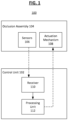
- FIG. 1 shows an implantable medical device 100, according to some embodiments.
- the implantable medical device 100 has a control unit 102 and an occlusion assembly 104 controlled and maintained by the control unit 102.
- the occlusion assembly 104 is configured to be implanted in an organ wall (e.g., a septum of a heart) and includes one or more sensor assemblies 106 as well as an actuation mechanism 108.
- the control unit 102 includes a receiver 110 which receives from the sensor assemblies 106 physiologic parameter information data as measured by the sensor assemblies 106, and a processing unit 112 coupled to the receiver 110 which is optionally configured to analyze the physiologic parameter information received by the receiver 110.
- the processing unit 112 can be a central processing unit (CPU), a system-on-a-chip (SoC), or any suitable processor. In some examples, the processing unit 112 completes analysis of the physiologic parameter information and determines to send a control signal to the actuation mechanism 108 associated with the occlusion assembly 104 to control the physiologic parameter within the heart.
- CPU central processing unit
- SoC system-on-a-chip
- the actuation mechanism 108 may be activated in response to the elevated blood pressure differential to reduce the differential between the left and right atrium blood pressures.
- the sensor assemblies 106 detect a single physiological measurement.
- the sensor assemblies 106 detect a relative or absolute measurement.
- the pressure measurements taken by the sensor assemblies 106 can be converted into a ratio of LAP to RAP.
- an ideal ratio of LAP to RAP is 2:1 is desirable. Therefore, any ratio that is significantly smaller or larger than the desired ratio would pose a threat to the health of the heart, so the actuation mechanism 108 is activated to let some of the blood flow from one atrium to the other atrium, as appropriate, to bring the ratio closer to the desirable ratio.
- the threshold value may be determined by the physician who then decides under which conditions should the actuation mechanism 108 be activated.
- data from a single sensor assembly may be reported and this data used by a physician (or algorithm) to determine whether the actuation mechanism should be activated. It should be noted that other physiologic measurements may be used to make this decision, as explained below.
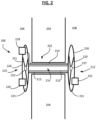
- FIG. 2 shows an implantable medical device 200, according to some embodiments.
- the implantable medical device 200 includes a fluid shunt 202 adapted to extend through an organ wall 204 (e.g., a septum) separating a first cavity 206 (e.g., a first heart chamber) and a second cavity 208 (e.g., a second heart chamber) within a body of a patient.
- the cavities are the left and right atria or the left and right ventricles, for example.
- one or more of the cavities are an aorta, a vena cava, or other vascular structure.
- the fluid shunt 202 includes a first portion 210 adapted to extend into the first cavity 206, a second portion 212 adapted to extend into the second cavity 208, and an intermediate portion 214 interconnecting the first portion 210 and the second portion 212.
- the fluid shunt 202 also has a lumen 216 extending through the intermediate potion 214 between first portion 210 and the second portion 212.
- the lumen 216 is adapted to provide a fluid path between, or to fluidly couple, the first cavity 206 with the second cavity 208.
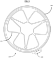
- FIGs. 3-5 show different embodiments and examples of the flanges as previously introduced.
- FIG. 3 shows the first flange 224 according to an embodiment where the first flange 224 engages with the organ wall 204 and is attached to an antenna 300.
- a sensor assembly 220 attaches to the antenna 300, and the antenna 300 is operative to send the physiologic measurement information provided by the sensor assembly 220.
- an occlusion assembly 218, as explained below, is also attached to the antenna 300.
- the antenna 300 is operative to receive the control signal sent to the occlusion assembly 218, or more specifically to the actuation mechanism 108 of the occlusion assembly 218.
- the implantable medical device 200 has a second flange 226 at the second portion 212 with a second flange cover 231 to prevent fluid flow between the lumen 216 and a second cavity 208.
- the first flange cover 223 and/or the second flange cover 231 include a composite membrane material, such as a polymer membrane.
- the polymer membrane is expanded polytetrafluoroethylene (ePTFE).
- the membrane can be any other suitable fluoropolymer, thermoplastic polymer, elastomer, biopolymer, fabric, textile, etc.
- the second flange 226 has a configuration that is similar, if not identical, to that of the first flange 224.
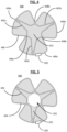
- FIGs. 4 and 5 show a first frame portion 400 according to an embodiment.
- the first frame portion 400 forms part of the first flange 224 of the implantable medical device 200.
- the first frame portion 400 may be covered by, or otherwise support flange cover 223 which may be configured to be impermeable to bodily fluids such as blood under physiologic conditions to act as a separator to help prevent fluid flow between the lumen 216 and the first cavity 206.
- the first frame portion 400 can include one or more outer lobes (e.g., a first outer lobe 406a, a second outer lobe 406b, and a third outer lobe 406c) and an inner frame portion 402 (which in this example defines three inner lobes 402a, 402b, and 402c).
- Each of the lobes 406a, 406b, and 406c may be attached to the inner frame portion 402 such that the lobes are equally spaced around the inner frame portion 402.
- the lobes may be attached to the inner frame portion 402 and/or to adjacent lobes at attachment points 408a, 408b, and 408c.
- the first lobe 406a is attached to the second lobe 406b at attachment point 408a
- the second lobe 406b is attached to the third lobe 406c at attachment point 408b
- the third lobe 406c is attached to the first lobe 406a at attachment point 408c.
- FIGs. 4 and 5 are described with reference to three lobes and three attachment points, the first frame portion 400 can have any number of lobes and respective attachment points as desired.
- the inner frame portion 402 can be any shape as desired.
- the inner frame portion 402 is substantially circular or substantially triangular (as shown in FIGs. 4 and 5 ).
- the inner lobes 402a, 402b, and 402c may extend into the first, second and third lobes 406a, 406b, 406c to define the shape of the inner frame portion 402.
- the first frame portion 400 includes the sensor assembly 220 attached thereto.
- the sensor assembly 220 is operatively coupled to the antenna 300 as shown in FIG. 3 .
- the second flange 226 of the implantable medical device 200 can include a second frame portion that has the same or a different number of lobes as the first frame portion 400.
- the first and second frame portions each have three lobes.
- the first frame portion 400 may include three lobes while the second frame portion includes two, four, five, or more lobes.
- the first frame portion 400 can have lobes that are larger, smaller, and/or a different shape than the lobes of the second frame portion.
- the first frame portion 400 can include one or more sensor assemblies (e.g., 220 and 222) and the antenna 300, as shown in FIG. 3 .
- the implantable medical device 200 may include a pattern of structural frame elements or other structural features that form the first flange 224 and/or the second flange 226.
- the pattern of structural frame elements may be arranged (e.g., project from) inside inner lobes 402a, 402b, and 402c, and may be included in any of the lobes of devices discussed herein.
- the pattern of structural frame elements can be arranged to form an open cell pattern.
- the pattern of structural frame elements can form a diamond cell pattern in the inner lobes 402a, 402b, and 402c that collapse and open during load and deployment of the implantable medical device 200 in a catheter.
- the pattern of structural frame elements may enhance radial strength during deployment and facilitate arrangement of the implantable medical device 200 in a deployed, or otherwise operative shape.
- FIG. 5 shows the first flange cover 223 after the actuation mechanism 108 creates a first aperture 225 in the cover 223 to allow for fluid flow through the lumen 216.
- the first aperture 225 is formed through mechanical or interventional procedures. In some embodiments, the first aperture 225 is formed through non-invasive procedures.
- the second portion 212 includes the second flange 226.
- the second flange 226 may be annular in shape, having a second aperture 227 and including a second flange support 229 and a second flange cover 231.
- the second flange support 229 can also be a resilient framework including one or more frame elements, which may be wound, woven, braided, cut, or otherwise formed.
- the second flange support 229 is formed of a shape memory material, such as a shape memory alloy (e.g., a nickel-titanium alloy).
- the second flange cover 231 optionally includes a membrane material (e.g., an ePTFE membrane) or other biocompatible material as desired.
- the second flange cover 226 is configured to promote or inhibit tissue ingrowth and/or is biodegradable under physiologic conditions over time.
- the intermediate portion 214 of the fluid shunt 202 includes a tubular member 215 and an intermediate support 213 configured to help maintain the shape of the tubular member 215 against compression and/or distortion forces exerted by the patient anatomy (e.g., the wall 204) and/or physiologic processes (e.g., blood pressure).
- the intermediate support 213 can also be a resilient framework including one or more frame elements, which may be wound, woven, braided, cut, or otherwise formed.
- the intermediate support 213 is formed of a shape memory material, such as a shape memory alloy (e.g., a nickel-titanium alloy).
- the tubular member 215 optionally includes a membrane material (e.g., an ePTFE membrane) or other biocompatible material as desired.
- a membrane material e.g., an ePTFE membrane
- the tubular member 215 is configured to promote or inhibit tissue ingrowth and/or is biodegradable under physiologic conditions over time.
- the implantable medical device 200 also includes the occlusion assembly 218, as mentioned above, associated with the fluid shunt 202.
- the occlusion assembly 218 is adapted to selectively occlude flow through the lumen 216 of the fluid shunt 202.
- the occlusion assembly 218 can be configured to be activated (via physical, manual intervention or via remote or automatic means) to adjust flow through the lumen 216 of the fluid shunt 202.
- the actuation mechanism 108 is configured to be actuated to permit fluid flow through the lumen 216, or to permit increased or decreased fluid flow through the lumen 216. In some examples, the actuation mechanism 108 is selectively activated to increase and decrease flow, for example by being actuatable to open or narrow the lumen 216.
- the actuation mechanism 108 is optionally positioned at the first portion 210, the second portion 212, and/or the intermediate portion 214.
- the actuation mechanism 108 may be "one-way" actuatable, in that the actuation mechanism 108 begins at a no-flow, or low-flow condition, and then can be opened (e.g., entirely or in stages), to increase flow. In other embodiments, the actuation mechanism 108 can both increase and decrease flow through the fluid shunt 202.
- the actuation mechanism 108 includes a needle or other suitable puncturing component to mechanically penetrate one or both of the flange covers 223 and 231.
- a needle is led to the location of the implantable medical device 200 by a catheter, and the needle is used to form the first aperture 225 by puncturing the first flange cover 223 and the second aperture 227 by puncturing the second flange cover 231.
- Other interventional procedures include mechanical, thermal, laser, ultrasound, and inductive methods.
- the actuation mechanism 218 is attached to the antenna 300.
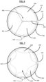
- the membrane defining the first flange cover 223 is made of three flap elements 600, 602, and 604 that are under radial tension, with a wire 606 fixing the three flap elements together with a stitch 608 as shown to prevent the radial tension from causing the flap elements to move toward the outer edge of the first flange 224.
- the sensor assembly 220 is located on the antenna 300. Upon receiving the actuation signal from the control unit 102, the actuation mechanism 218 pulls the wire 606 to cause the flap elements 600, 602, and 604 to be pulled back toward the outer edge, thereby creating the first aperture 225 as shown in FIG. 7 .
- the wire 606 can be made of any suitable material.
- the wire 606 is a thread made of polymers such as nylon or PTFE.
- the wire 606 is made of a conductive material, such as stainless steel or nickel-titanium alloy, among others.
- the same actuation mechanism may also be attached to the second flange cover 231, with the second flange cover 231 also made of similar flap elements.
- the number of flap elements may be two. In other examples, the number of flap elements may be four or more.
- the wire 606 is conductive, and upon receiving the actuation signal from the control unit 102, the occlusion assembly 218 applies a voltage to the wire 606 to cause the wire 606 to undergo electrolytic degradation. After undergoing sufficient degradation, the wire 606 breaks or dissolves and can no longer hold the flap elements 600, 602, and 604 together. As such, the flap elements 600, 602, and 604 retract or open from the initial position shown in FIG. 6 , thereby creating the first aperture 225 as shown in FIG. 7 .
- the actuation mechanism 108 is external to the body, such as an extracorporeal energization unit 800.
- FIG. 8 illustrates the implantable medical device 100 or 200. Energy is inductively supplied to the implantable medical device using the extracorporeal energization unit 800 in a treatment system according to an embodiment.
- the energization unit 800 can include an extracorporeal induction energy source which supplies power to the implanted medical device so that electrical energy can electrolytically degrade an element 606 thereby forming the first aperture 225, converting the device to an open configuration.
- the control unit 102 is configured to be located external to the body and controls the extracorporeal energization unit 800.
- the treatment system which operates to control the first aperture 225 in the implantable medical device 200 includes one or more of: an internal induction energy receiver, an ultrasonic energy source, a laser energy source, a radiofrequency (RF) energy source, and/or another type of energy source for activating the occlusion assembly 104.
- the implantable medical device 200 when the first aperture 225 is formed and fluid flow is allowed within the lumen 216, the implantable medical device 200 exhibits different resonant frequencies based upon a flow rate through the lumen 216. The resonant frequency can be measured using one or both of the sensor assemblies 220 and 222 coupled to the implantable medical device 200.
- the resonant frequency measured by the receiver 110 is converted to a physiologic parameter such as the fluid flow rate by the processing unit 112.
- both of the sensor assemblies 220 and 222 are pressure sensors, so the flow rate of fluid through the lumen 216 is estimated based upon the lumen's dimensions, the pressure differential, and the known fluid dynamic characteristics of the fluid, which may be blood. Additional or alternative sensing features are contemplated.
- a shift in resonant frequency measured by the sensor assembly 220 or 222 provides verification that the lumen 216 is successfully opened to allow fluid flow therethrough.
- the wireless extracorporeal energization includes inductive energy transfer or ultrasound energy transfer, which are nonlimiting examples of the noninvasive procedures.
- a membrane of the flange cover 223 can be melted to form the aperture 225 after exposing the flange cover 223 to thermal or ultrasound energy, to produce a thermal activation mechanism.
- the size of the aperture 225 can be adjusted by varying the amount of thermal activation.
- the aperture 227 in the flange cover 231 may be formed using the same method/mechanism as any of those described in association with the flange cover 223, or by differing methods as desired.
- the flange cover 223 is made of at least one flap element which is controlled mechanically by the actuation mechanism 108, which is in turn controlled wirelessly by the control unit 102.
- mechanism control is accomplished by the actuation mechanism 108 pulling on the flap element to change the state of the flap element from a closed state to a more open state.
- the size of the aperture 225 can be adjusted by varying how much the flap element is to be displaced from the closed position.
- the actuation mechanism 108 can also control the flap element to decrease the size of the aperture 225 by returning the position of the flap element closer to the closed position.
- the controlling of the at least one flap element is done by the actuation mechanism 108 of the occlusion assembly 218 applying a voltage to induce electrolytic degradation of the wire (for example, the wire 606 shown in FIG. 6 ) which holds the at least one flap element in the closed state, thereby causing the at least one flap element to change from the closed state to a more open state.
- a voltage to induce electrolytic degradation of the wire for example, the wire 606 shown in FIG. 6
- one or both of the covers 223 and 231 are made of a membrane that is selectively absorptive to ultrasound such that the membrane is configured to be thermally opened using an ultrasound source to adjust flow through the lumen 216 of the fluid shunt 214.
- one or both of the covers 223 and 231 are made of a membrane that is selectively absorptive to RF energy such that the membrane is thermally opened using an RF ablation source to adjust flow through the lumen 216 of the fluid shunt 214.
- the membrane is selectively absorptive to laser energy such that the membrane is configured to be thermally opened using a laser source.
- the membrane or the elements (e.g., wires) holding the membrane in place are selectively and electrolytically degradable using electrical energy supplied by an induction energy source.
- the electrical energy can be supplied by any suitable means such as a battery, a piezoelectric receiver exposed to an ultrasonic energy source, magnetic induction, a radiofrequency (RF) energy source, and/or another type of energy source for activating the occlusion assembly.
- both covers 223 and 231 are actuatable utilizing similar methods.
- the covers 223 and 231 can both be configured to open simultaneously in response to receiving energy from an external source, e.g. RF energy, laser energy, induction energy, or others.
- one or both of the covers 223 and 231 are under radial tension to assist with forming one or both of the apertures 225 and 227.
- the cover(s) 223 and 231 are stretched, even a small opening in the covers can be enlarged when the radial tension placed from the outer edge of the covers pull the cover material surrounding the opening away from the locations of the openings in a plurality of directions.
- the cover(s) exhibit residual stress profile to assist with forming the one or both of the apertures 225 and 227 in the cover.
- the cover(s) are selectively openable between a plurality of sizes for the one or both of the apertures 225 and 227 to modify flow through the lumen 216.
- FIG. 9 shows a sensor system 900 implemented in one embodiment of the implantable medical device 100.
- the sensor system 900 includes one or more sensor assemblies 106 and a sensor control unit 902 in communication with the one or more sensor assemblies 106.
- the one or more sensor assemblies 106 are active sensors that include transmitters that send out a signal and records the environmental response to the signal.
- the one or more sensor assemblies 106 are passive sensors that require external energy sources to perform physiological measurements, for example upon receipt of an input from the physical environment.
- the sensor control unit 902 includes a battery 904, a receiver 906, and a transmitter 908.
- the battery 904 provides power for the sensor assemblies 106 to continue taking physiological measurements as well as for the sensor control unit 902 to receive and transmit data of said measurements.
- the receiver 906 receives the measurement data from the sensor assemblies 106, and the transmitter 908 transmits the data, for example wirelessly, to the external control unit 102.
- the one or more sensor assemblies 106 include a first sensor assembly 220 associated with the first portion 210 of the fluid shunt 202 adapted to sense one or more physiologic parameters in the first cavity 206 and a second sensor 222 associated with the second portion 212 of the fluid shunt 214 adapted to sense one or more physiologic parameters in the second cavity 208 within the heart.
- a first sensor assembly 220 associated with the first portion 210 of the fluid shunt 202 adapted to sense one or more physiologic parameters in the first cavity 206
- a second sensor 222 associated with the second portion 212 of the fluid shunt 214 adapted to sense one or more physiologic parameters in the second cavity 208 within the heart.
- two sensor assemblies are shown and described, greater (e.g., three or more) or fewer (e.g., a single sensor) are contemplated.
- one or all of the sensor assemblies 106 are configured to sense a physiologic parameter including blood pressure levels in the respective cavities.
- one or more sensor assemblies 106 are configured to sense the rate at which blood flows in the designated cavity within the heart. In still further examples, one or more sensors are configured to sense temperature of the blood. In still other examples, one or more sensors are configured to sense oxygen saturation of the blood.
- suitable sensors capable of measuring fluid flow or pressure inside an organ include piezoelectric sensors, pressure switches, optical pressure transducers, Venturi meters, impedance monitors, and ultrasonic pressure sensors, as well as other types of electrophysiologic and hemodynamic sensors.
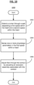
- FIG. 10 shows a method 1000 of operating the implantable medical device 200 according to one embodiment.
- the lumen 216 is extended through the wall 204 separating the first cavity 206 within the heart and the second cavity 208 within the heart.
- the fluid shunt 214 is passed through the wall 204 of the heart, including engaging flange portions, or anchors 224 and 226, of the first portion 210 and the second portion 212 of the fluid shunt 214 with the wall 204 of the heart.
- the first sensor assembly 220 senses one or more physiologic parameters in the first cavity 206.
- the flow through the fluid shunt 214 is adjusted by actuating the occlusion assembly 218 associated with the fluid shunt 214.
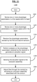
- FIG. 11 shows another method 1100 of operating the implantable medical device 200 according to some embodiments.
- the second sensor 222 senses one or more physiologic parameters in the second cavity 208 within the heart.
- the receiver 110 receives the physiologic parameters sensed by the first sensor assembly 220 and the second sensor 222.
- the processing unit 112 performs analysis on the physiologic parameters received by the receiver 110 to generate an actuation signal.
- the control unit 102 sends the actuation signal to the occlusion assembly 218.
- the flow through the fluid shunt 214 is adjusted by actuating the occlusion assembly 218 associated with the fluid shunt 214 according to the actuation signal provided by the processing unit 112 of the control unit 102.
- control unit 102 sends the actuation signal to the occlusion assembly 218 upon the first sensor assembly 220 and the second sensor 222 sensing a predetermined differential physiologic measurement such that the occlusion assembly 218 increases flow through the lumen 216 by performing one or more of the procedures as explained above.
- FIG. 12 is an image of a first side of the implantable medical device 200, where the first frame portion 400 of the first flange 224 as shown in FIGs. 4 and 5 is visible, including a covering material for the flange cover 223, in accordance with an embodiment.
- the covering material 223 can be arranged over the opening or aperture 225.
- the covering material 223 may act to slow or occlude flow through the first frame portion 400 as desired.
- the covering material 223 can be arranged over the first frame portion 400.
- the covering material 223 may be attached to one or more of the first lobe 406a, the second lobe 406b, and the third lobe 406c.
- the inner frame portion 402 serves as the second frame portion 1300, as shown and discussed with reference to FIG. 13 .
- the sensor assembly 220 is located on one or more of the first lobe 406a, the second lobe 406b, and the third lobe 406c.
- FIG. 13 is an image of a second side of the implantable medical device 200, in accordance with an embodiment.
- the covering material 231 is arranged over the opening 227.
- the first, second, and third lobes 1302a, 1302b, and 1302c of the second frame portion 1300 may or may not include the covering material 231.
- the covering material 231 is arranged over the opening 27 but not over the second frame portion 1300, while in other examples, the covering material 231 may be arranged over both the opening 227 and the second frame portion 1300, for example.
- the sensor assembly 224 is located on one or more of the first lobe 1302a, the second lobe 1302b, and the third lobe 1302c.
- FIG. 14 shows an implantable medical device 1400 with two flanges 224 and 226 attached to a surface of the organ wall 204 according to an embodiment, where the first and second flanges are located on opposite sides of the organ wall with conduit extending through the organ wall.
- the organ wall 204 is an atrial wall between a left atrium and a right atrium of a heart, such that the first flange 224 is located on a surface of the atrial wall 204 in the right atrium, and the second flange is located on a surface of the atrial wall 204 in the left atrium with a conduit 1402 extending between the two flanges 224 and 226 such that the conduit 1402 forms the lumen 216 fluidly connecting the two atria of the heart.
- the conduit 1402 includes a cover material, such as a membrane that has high rigidity and stiffness, for example one made of a polymer material such as fluoroelastomer, high-density polyethylene, polyethylene terephthalate (PTE), polyvinyl chloride (PVC), polyamide, polycarbonate, polymethylpentene, polypropylene, polystyrene, polysulfone, or others, in order for the membrane to exert radial force against the wall 204 to prevent the lumen 216 from collapsing.
- a cover material such as a membrane that has high rigidity and stiffness
- a polymer material such as fluoroelastomer, high-density polyethylene, polyethylene terephthalate (PTE), polyvinyl chloride (PVC), polyamide, polycarbonate, polymethylpentene, polypropylene, polystyrene, polysulfone, or others, in order for the membrane to exert radial force against the wall 204 to prevent
- the conduit 1402 includes one or more structural elements (e.g., stent elements) made of a suitable material, such as shape memory alloy (e.g., a nickel-titanium alloy) or stainless steel, for example.
- the medical device 1400 includes a cover 1404, such as a flexible membrane of any suitable polymer material include but not limited to ePTFE.
- the cover 1404 is located or is otherwise configured to reside between the first flange 224 and the wall 204.
- the medical device 1400 includes one or more (e.g., three) locations to place one or more sensors to perform physiological measurements within the body.
- a sensor e.g., a pressure sensor
- a sensor e.g., a flow sensor
- a sensor e.g., a flow sensor
- a sensor e.g., a pressure sensor
- a single sensor performing a single sensing function is placed at each location, whereas in other examples, a plurality of sensors, or a sensor performing a plurality of sensing functions, can be placed at each location.
- FIG. 15 shows the implantable medical device 1400 as shown in FIG. 14 with an additional, secondary cover 1500 (e.g., of flexible membrane material such as those previously described) according to an embodiment.
- the covers 1404 and 1500 are selectively absorptive to RF energy such that the covers are thermally opened using an RF ablation source to adjust flow through the lumen 216.
- the covers 1404 and 1500 are selectively absorptive to laser energy such that each cover is configured to be thermally opened using a laser source.
- the covers 1404 and 1500 are selectively absorptive to ultrasound energy such that each cover (1404 and/or 1500) is configured to be thermally opened using an ultrasound source.
- the covers 1404 and 1500 or the elements (e.g., wires) holding the covers in place are selectively and electrolytically degradable using electrical energy supplied by an induction or other energy source.
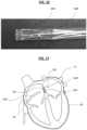
- FIG. 16 shows the implantable medical device 1400 in a compressed configuration inside a deployment apparatus 1600, in accordance with an embodiment.
- the device 1400 is compressed into a delivery configuration and loaded into the deployment apparatus 1600 to be delivered to a desired treatment location within the patient's body.
- the device 1400 is loaded into the deployment apparatus 1600 such that the device 1400 is completely contained within the deployment apparatus 1600, as shown in FIG. 16 .
- the device 1400 can be delivered to the desired treatment location while in the delivery configuration.
- the first flange 224 is then positioned on a first side of the wall 204 and the flange 226 is positioned on a second side of the wall 204.
- the central portion or the conduit 1402 of the device 1400 can be radially expanded or compressed/restricted to adjust the rate of fluid flow through the opening as desired.
- the deployment apparatus 1600 includes a catheter or a sheath.
- FIG. 17 shows an example of using the implantable medical device 1400 for regulating blood pressure in accordance with an embodiment.
- the implantable medical device 1400 is shown implanted within a heart H of a patient.
- the device 1400 is shown arranged between the patient's left atrium LA and right atrium RA.
- the device 1400 may be used to regulate blood flow within the heart H, for example, between the left and right atria LA, RA.
- the device 1400 generally includes the first flange 224 arranged on a first side of a septum (e.g., within the right atrium RA), the second flange 226 arranged on a second side of the septum (e.g., within the left atrium LA), and the conduit 1402 extending therethrough.
- a needle may be used to create or open a trans-septal opening in the septum.
- the deployment apparatus 1600 and constraining and/or release lines may be used to facilitate deployment of the device 1400.
- the second flange 226 of the device 1400 may be released first after the deployment apparatus 1600 is advanced through the organ wall (e.g., septum) and into a desired internal cavity (e.g., the LA), and the first flange 224 may be released on an opposite side of the organ wall (e.g., on the RA side of the atrial septum).
- the conduit 1402 can be arranged within the opening in the organ wall (e.g., the trans-septal opening).
- the flanges 224 and 226 as well as the conduit 1402 may be compressed within the deployment apparatus 1600 during delivery of the device 1400 to the desired treatment area within the patient and subsequently expanded during deployment of the device 1400. After deployment, the device 1400 can then be used to carry out one or more treatment programs on the patient. In one example, the device 1400 detects and treats pulmonary congestion and pulmonary hypertension by taking physiologic measurements using the sensors in one or more locations within the heart.
- the sensors of the medical device 1400 detects a condition, and the conduit 1402 is opened by activating the occlusion assembly 218, for example, to allow blood flow through the lumen 216, thereby decreasing the pressure within the left atrium to a safe level.
- FIG. 18 shows an example of an implantable medical device 1800 for regulating blood pressure in accordance with an embodiment.
- the implantable medical device 1800 includes the first frame component 1802 and the second frame component 1804.
- the first frame component 1802 may be configured to conform to the patient's anatomy (i.e., the first side of the septum, for example).
- the second frame component 1804 may be configured to conform to the patient's anatomy (i.e., the second side of the septum).
- the sensor assembly 220 is located on one or both of the first frame component 1802 and the second frame component 1804.
- the first frame component 1802 includes a first set of elongate elements 1806, and the second frame component 1804 includes a second set of elongate elements 1808.
- the frame components 1802, 1804, including and for example the elongate elements 1806, 1808, may be discrete and separate from one another.
- the first frame component 1802 forms a first side 1810 of the device 1800 and the second frame component 1804 forms a second side 1812 of the device 1800.
- the first frame component 1802 being discrete and separate from the second frame component 1804 does not enter into the second side 1812 of the device and the second frame component 1804 being discrete and separate from the first frame component 1802 does not enter into the first side 1810 of the device.
- first and second frame components 1802, 1804 are non-contiguous with one another.
- the first and second frame components 1802, 1804 being non-contiguous with one another allows the first and second frame components 1802, 1804 to be distinct and separate from one another.
- the first and second frame components 1802, 1804 are free to move, in response to movement of the patient's anatomy, separate from one another. In this manner, forces acting on one of the first and second frame components 1802, 1804 are maintained within the other of the first and second frame components 1802, 1804.
- the forces acting on one of the first and second frame components 1802, 1804 may be isolated to the frame component to which the force is acted on.
- the conduit portion 1814 is arranged between the first frame component and the second frame component. At least a portion of the conduit portion 1814 is generally radially or circumferentially unsupported by the first and second frame components 1802, 1804 within the conduit portion 1814. As shown in FIG. 18 , the conduit portion 1814 transitions to the first side 1810 and the second side 1812 at approximately a 90 degree angle (other angles are contemplated). Bounds of the conduit portion 1814 may be considered to be a location at which the conduit portion 1814 transitions to the first side 1810 and the second side 1812. The first and second frame components 1802, 1804 extend laterally relative to the conduit portion 1814.
- first and second frame components 1802, 1804 may support the conduit portion 1814 without substantially entering the bounds of the conduit portion 1814. In certain instances, the first and second frame components 1802, 1804 support the conduit portion 1814 laterally from outside of bounds the conduit portion 1814. Thus, the first and second frame components 1802, 1804 may maintain a lumen through the conduit portion 1814 and facilitate deployment of the conduit portion 1814 by laterally forcing the conduit portion 1814 open.
- first and second frame components 1802, 1804 may impart tension to the conduit portion 1814 to deploy and maintain the conduit portion 1814 with a lumen therethrough.
- the conduit portion 1814 may be deployed within the septum between tissue surfaces through an opening (e.g., needle stick across the septum) that has a diameter smaller than a fully deployed diameter of the conduit portion 1814.
- Tension in the conduit portion 1814 imparted by expansion of the first and second frame components 1802, 1804 may also expand the septum between tissue surfaces to a desired shunt size.
- the conduit portion 1814 may be substantially free of frame components.
- the conduit portion 1814 may include, for example, a membrane 1816, such as an expanded polytetrafluoroethylene (ePTFE) membrane, connecting the first frame component 1802 and the second frame component 1804.
- ePTFE expanded polytetrafluoroethylene
- the membrane 1816 generally separates the first frame component 1802 and the second frame component 1804 by a suitable distance compatible with the patient's body.
- the membrane 1816 can separate the first frame component 1802 and the second frame component 1804 by a gap of from 0 to 15 mm depending on the desired treatment location within the patient's body.
- the conduit portion may be formed of only the membrane 1816.
- the conduit portion 1814 which is configured to be deployed within the septum between tissue surfaces, is free of the first frame component 1802 and the second frame component 1804.
- the conduit portion 1814 may include a smooth interior that facilitates blood flow therethrough without ridges from a stent element interrupting or disrupting flow. Thus, the conduit portion 1814 may lessen the opportunity for thrombosis.
- the membrane 1816 may also cover at least a portion of the first frame component 1802, at least a portion of the second frame component 1804, or at least a portion of the first frame component 1802 and the second frame component 1804.
- the membrane 1816 arranged on at least a portion of the first frame component 1802 and/or the second frame component 1804 is a separate membrane film (e.g., a first membrane film arranged on first frame component 1802 and a second membrane film arranged on the second frame component 1804).
- the membrane film or films may be coupled to the membrane 1816 in the conduit portion 1814.
- the membrane 1816 may be elastic to allow for expansion of the conduit portion 1814 and to allow for movement of portions of the first frame component 1802 and/or the second frame component 1804 (e.g., movement of the first set of elongate elements 1806 and/or the second set of elongate elements 1808).
- the membrane 1816 may span gaps between the first set of elongate elements 1806 and/or the second set of elongate elements 1808.
- the membrane 1816 in certain instances, is arranged on at least a tissue engaging side of the first frame component 1802 and a tissue engaging side the second frame component 1804. In these instances, the membrane 1816 is configured to lessens frame erosion potential of the first frame component 1802 and/or the second frame component 1804.
- the membrane 1816 and the arrangement of the first set of elongate elements 1806 and/or the second set of elongate elements 1808 may conform to the tissue surfaces surrounding the septum.
- the first set of elongate elements 1806 and/or the second set of elongate elements 1808 may lay flat against the tissue surfaces.
- each of the first set of elongate elements 1806 may be attached to one another via the membrane 1816 to form the first frame component 1802.
- the first frame component 1802 may form a substantially flat or 2-dimensional, disc-like shape, as shown.
- the second set of elongate elements 1808 may also be attached to one another via the membrane material 1816 to form the second frame component 1804.
- the second frame component 1804 may also form a substantially flat or 2-dimensional, disc-like shape such that the first and second frame components 1802, 1804 are substantially parallel to one another when the device 1800 is in a deployed configuration.
- the membrane 1816 may be configured to promote or inhibit tissue ingrowth over at least a portion of the membrane 1816, or at least a portion of the membrane 1816. In certain instances, the membrane 1816 is configured to promote or inhibit tissue ingrowth to cover at least a portion of the first and/or second frame components 1802, 1804, which may further promote compatibility and stability of the device 1800 within the patient's body.
- the membrane 1816 within the conduit portion 1814 may be configured to not allow tissue ingrowth leading to increased patency.
- the membrane 1816 is configured to promote endothelization without obstructive ingrowth within the conduit portion 1814. The membrane 1816 may promote endothelization without obstructive overgrowth of tissue into the conduit portion 1814.
- the device 1800 may be capable of delivering a drug to the desired treatment location within the patient's body.
- the device 1800 may be capable of eluting a drug configured to modulate tissue response.
- the device 1800 may be coated with a therapeutic coating, drug eluting material or other therapeutic material or a hydrophilic coating.
- the device 1800 can be coated with heparin to facilitate thromboresistance and patency of the device 1800.
- the device 1800 may include paclitaxel (to modulate tissue/cellular response).
- FIG. 19 is a perspective view of another example of an implantable medical device 1900 for regulating blood pressure in accordance with an embodiment.
- each of the first set of elongate elements 1806 may be discrete and separate from adjacent elongate elements.
- the membrane 1816 does not connect each of the first set of elongate elements 1806 together.
- each of the first set of elongate elements 1806 may move independently from one another and individually conform to the topography of the first side of the septum, thus providing a highly conformable first frame component 1802.
- Each of the second set of elongate elements 1808 may also be discrete and separate from adjacent elongate elements.
- each of the second set of elongate elements 1808 may move independently from one another and individually conform to the second side of the septum, much like the first set of elongate elements 1806 conforms to the first side of the septum.
- both the first and second frame components 1802, 1804 are highly conformable and may conform independently of one another based on the patient's anatomy.
- one of the first or second set of elongate elements 1806, 1808 of the first and second frame components 1802, 1804 may be attached to one another via the membrane 1816 while the other set of elongate elements are unattached (e.g., they are discrete and separate from adjacent elongate elements). In other instances, only some of the first or second set of elongate elements 1806, 1808 may be attached to one another, while other elongate elements of the first and second set of elongate elements 1806, 1808 are not attached.
- the device 1900 can be highly customizable to the patient depending on the desired treatment location within the patient, and size and/or shape of the defect, among other factors.
- the sensor assembly 220 is located on one or both of the first frame component 1802 and the second frame component 1804.
- the device 1900 is generally deployable or expandable from a delivery configuration to the deployed configuration.
- the first set of elongate elements 1806 and the second set of elongate elements 1808 may nest within one another when the device is in the delivery configuration. This allows the device 1900 to compress to a smaller size, for example, for delivery of the device 1900 to a wider variety of treatment locations (e.g., through small, narrow, or convoluted passageways).
- FIG. 20 is a side view of the implantable medical device 1900 for regulating blood pressure, shown in FIG. 19 , in accordance with an embodiment.
- FIG. 20 shows the device 1900 in the deployed configuration.
- the first frame component 1802 including the first set of elongate elements 1806 and the second frame component 1804 including the second set of elongate elements 1808 are positioned radially outward with respect to a longitudinal axis L of the conduit portion 1814 when the device 1900 is in the deployed configuration.
- the first and second frame components 1802, 1804 are positioned at first and second angles 2000, 2002, respectively.
- the first and second angles 2000, 2002 may form approximately a 90° angle with respect to the longitudinal axis L when the device is in the deployed configuration.
- first and second frame components 1802, 1804 may be positioned parallel with and adjacent to the first and second sides of the septum.
- the first and second frame components 1802, 1804 may be positioned at any angle relative to the longitudinal axis L (for example, from about 0° to greater than 90° with respect to the longitudinal axis L) that allows for contact with the tissue surface of the first and second sides of the septum.
- the first and second elongate elements 1806, 1808 are configured to separate from one another when the device 1900 is in the deployed configuration. As shown in FIG. 20 , each of the first set of elongate elements 1806 are discrete and separate from one another when the device 1900 is in the deployed configuration such that each of the first set of elongate elements 1806 may move independently from adjacent elongate elements. Each of the second set of elongate elements 1808 may also be discrete and separate from one another when the device 1900 is in the deployed configuration such that each of the second set of elongate elements 1808 move independently from adjacent elongate elements.
- the sensor assembly 220 may be located on any one or more of the first set of elongate elements 1806, and the other sensor assembly 222 may be located on any one or more of the second set of elongate elements 1808.
- the first and second frame components 1802, 1804 may maintain a lumen through the conduit portion 1814 and facilitate deployment of the conduit portion 1814 by laterally forcing the conduit portion 1814 open.
- the lumen may be free or without the first and second frame components 1802, 1804.
- the conduit portion 1814 may facilitate re-crossing of the septum for addition procedures (e.g., left atrial appendage occluder implantation).
- the first and second frame components 1802, 1804 may be differently configured. For example, one of the first and second frame components 1802, 1804 may be flared while the other of the first and second frame components 1802, 1804 is flat. In other instances, both the first and second frame components 1802, 1804 may be flared.
- first and second frame components 1802, 1804 may be convex while the other of the first and second frame components 1802, 1804 is flat or concave or both the first and second frame components 1802, 1804 may be convex. Further, one of the first and second frame components 1802, 1804 may be concave while the other of the first and second frame components 1802, 1804 is flat or convex or both the first and second frame components 1802, 1804 may be concave. In addition, the first and second frame components 1802, 1804 may be different sizes.
- the first and second frame components 1802, 1804 may include a sensor integrated into the respective frame component, for example, for continuous monitoring of various hemodynamic parameters such as pressure, among other parameters, within the patient's body.
- a sensor integrated into the respective frame component, for example, for continuous monitoring of various hemodynamic parameters such as pressure, among other parameters, within the patient's body.
- an antenna or inductor may be wrapped around the perimeter of one of the first and second frame components 1802, 1804 and the sensor may be attached to the inductor.
- the sensor may be configured to, for example, sense physiologic properties, such as temperature, electrical signals of the heart, blood chemistry, blood pH level, hemodynamics, biomarkers, sound, pressure, and electrolytes that may be important in diagnosing, monitoring, and/or treating heart disease, heart failure, and/or other cardiovascular disease states
- the conduit portion 1814 may be sizeable after delivery.
- the membrane 1816 may be selectively adjustable by a balloon applied within the conduit portion 1814 to distend the membrane 1816.
- the device 1900 can be any size suitable to fit the anatomy of the patient.
- a diameter of the conduit portion is from 3 to 12 mm.
- the diameter of the conduit portion may be from 4 to 10 mm, or from 5 to 8 mm depending on the anatomy of the patient and/or the desired treatment location.
- the first and second frame components 1802, 1804 generally have a larger diameter than that of the conduit portion 1814, for example, so that the frame components may anchor the conduit portion 1814 of the device 1900 within the septum.
- the device 1900 can be any shape suitable to fit the anatomy of the patient.
- the first and second frame portions 1802, 1804 may be any of a variety of suitable shapes for anchoring the device 1900 within the patient's body.
- the first and second frame portions 1802, 1804 may be substantially circular, ovular, diamond-shaped, star-shaped, flower-shaped, or any other suitable shape as desired.
- at least one of the first and second set of elongate elements 1806, 1808 form a star shape.
- both the first and second set of elongate elements 1806, 1808 form a star shape.
- the first set of elongate elements 1806 forms a plurality of first lobes 2004 and the second set of elongate elements 1808 forms a plurality of second lobes 2006.
- Each of the plurality of first and second lobes 2004, 2006 may include, for example, from 3 to 12 lobes, from 4 to 10 lobes, or from 6 to 8 lobes as desired.
- the plurality of first lobes 2004 may have more lobes than the plurality of second lobes 2006, while in other instances, the plurality of first lobes 2004 may have the same number of lobes or less lobes than the plurality of second lobes 2006.
- FIG. 21 shows an example of an implantable medical device 1400 being activated by an energy source, for example an energization unit 2100, in accordance with an embodiment.
- the energization unit 2100 functions in a way similar to the extracorporeal energization unit 800 in that the energization unit 2100 can transmit energy to the implantable medical device via magnetic induction and this energy can be converted to electrical energy to electrolytically degrade an element of the implanted medical device.
- the energization unit 2100 can deliver energy via an ultrasonic energy source, a laser energy source, a radiofrequency (RF) energy source, and/or another type of suitable energy source, which applies an energy transfer 2102 to form an aperture in a membrane coupled to a flange, for example a membrane 2104 coupled to the first flange 224.
- the energization unit 2100 is delivered to a location within the heart H (e.g., in the right atrium RA) that is proximate to the membrane 2104.
- a membrane of the membrane 2104 can be melted to form the aperture after exposing the membrane 2104 to thermal or ultrasound energy, to produce a thermal activation mechanism.
- the size of the aperture can be adjusted by varying the amount of thermal activation.
- the medical device 1400 may include an additional, secondary membrane (not shown) coupled to the second flange 226.
- one or both of the membranes are selectively absorptive to ultrasound such that the membranes are configured to be thermally opened using an ultrasound source to adjust flow through the medical device 1400.
- one or both of the membranes are selectively absorptive to RF energy such that the membranes are thermally opened using an RF ablation source to adjust flow through the medical device 1400.
- the membrane is selectively absorptive to laser energy such that the membrane is configured to be thermally opened using a laser source.
- the membrane or the elements (e.g., wires) holding the membrane in place are selectively and electrolytically degradable using electrical energy supplied by an induction or other energy source.
- both membranes are actuatable utilizing similar methods.
- the membranes can both be configured to open simultaneously in response to receiving energy from an external source, e.g. RF energy, laser energy, induction energy, or others.
- one or both of the membranes are under radial tension to assist with forming one or both of the apertures therethrough. For example, when the membrane(s) are stretched, even a small opening in the membrane(s) can be enlarged when the radial tension placed from the outer edge of the membrane(s) pull the membrane(s) away from the locations of the openings in a plurality of directions.
- the membrane(s) exhibit residual stress profile to assist with forming the one or both of the apertures in the membrane(s).
- the membrane(s) are selectively openable between a plurality of sizes for the one or both of the apertures to modify flow through the medical device 1400.
- FIG. 22 shows an example of an implantable medical device 2200 according to an embodiment.
- the implantable medical device 2200 has two flanges 224 and 226 engaged with a surface of the organ wall 204 to secure the medical device 2200 in place, where the flanges 224 and 226 are located on opposite sides of the organ wall 204.
- the organ wall 204 is an atrial wall between a left atrium and a right atrium of a heart, such that the first flange 224 is located on a surface of the atrial wall 204 in the right atrium, and the second flange is located on a surface of the atrial wall 204 in the left atrium with a conduit 1402 extending between the two flanges 224 and 226 such that the conduit 1402 forms the lumen 216 fluidly connecting the two atria of the heart.
- the medical device 2200 is secured to a ventricular wall or other tissue of the body as desired.
- the conduit 1402 includes a membrane 2202 made of a polymer material as described above that is impermeable to blood under physiologic conditions such that the membrane 2202 separates the lumen 216 into two sections: a first lumen section 216A and a second lumen section 216B.
- the membrane 2202 is positioned in the middle of the lumen 216, though the membrane may be offset toward or located at either end of the lumen 216.
- the membrane 2202 is positioned at any location in the lumen 216 such that the first lumen section 216A has a greater volume than the second lumen section 216B or vice versa.
- the membrane 2202 helps prevent fluid flow through the lumen 26 (e.g., between the first and second lumen sections 216A and 216B), and therefore between the two opposite sides of the organ wall 204.
- the membrane 2202 can be selectively absorptive to ultrasound, RF energy, laser energy, or any suitable source of energy as previously described, in which case absorbing the energy causes the membrane 2202 to degrade, melt, or open to allow fluid to flow between the first and second lumen sections 216A and 216B.
- the amount of fluid flow can be adjusted by changing a degree of degradation or a size of the opening in the membrane 2202.
- the medical device 2200 includes one or more (e.g., three) locations to place one or more sensors to perform physiological measurements within the body.
- the first location 1406 and the third location 1410 are essentially similar to those mentioned above with respect to the medical device 1400.
- the second location 1408 can be inside the conduit 1402 for the sensor (e.g. a flow sensor) to measure the flow of fluid within the lumen 216.
- the second location 1408 can be located in the first lumen section 216A or the second lumen section 216B.
- the second location 1408 can be adjacent to or proximate to the membrane 2202 such that the sensor would also be able to detect when the membrane 2202 is opened or degraded to permit fluid flow through the lumen 216.
Landscapes
- Health & Medical Sciences (AREA)
- Life Sciences & Earth Sciences (AREA)
- Engineering & Computer Science (AREA)
- Physics & Mathematics (AREA)
- Veterinary Medicine (AREA)
- Public Health (AREA)
- General Health & Medical Sciences (AREA)
- Animal Behavior & Ethology (AREA)
- Heart & Thoracic Surgery (AREA)
- Biomedical Technology (AREA)
- Surgery (AREA)
- Molecular Biology (AREA)
- Medical Informatics (AREA)
- Pathology (AREA)
- Biophysics (AREA)
- Cardiology (AREA)
- Physiology (AREA)
- Vascular Medicine (AREA)
- Pulmonology (AREA)
- Optics & Photonics (AREA)
- Computer Networks & Wireless Communication (AREA)
- Medicinal Chemistry (AREA)
- Pharmacology & Pharmacy (AREA)
- Chemical & Material Sciences (AREA)
- Bioinformatics & Cheminformatics (AREA)
- Urology & Nephrology (AREA)
- Biodiversity & Conservation Biology (AREA)
- Transplantation (AREA)
- Epidemiology (AREA)
- Artificial Intelligence (AREA)
- Computer Vision & Pattern Recognition (AREA)
- Psychiatry (AREA)
- Signal Processing (AREA)
- Oral & Maxillofacial Surgery (AREA)
- Spectroscopy & Molecular Physics (AREA)
- Ophthalmology & Optometry (AREA)
- Hematology (AREA)
- Otolaryngology (AREA)
- Anesthesiology (AREA)
- Measuring Pulse, Heart Rate, Blood Pressure Or Blood Flow (AREA)
Claims (16)
- Implantierbare medizinische Vorrichtung 200, umfassend:einen Fluidshunt 202, der ausgelegt ist, um sich durch eine Wand 204 zu erstrecken, die einen ersten Hohlraum 206 und einen zweiten Hohlraum 208 innerhalb des Herzens trennt,wobei der Fluidshunt 202 einen ersten Abschnitt 210, der ausgelegt ist, um sich in den ersten Hohlraum 206 innerhalb des Herzens zu erstrecken, einen zweiten Abschnitt 212, der ausgelegt ist, um sich in den zweiten Hohlraum 208 innerhalb des Herzens zu erstrecken, und einen Zwischenabschnitt 214, der den ersten 210 und den zweiten Abschnitt 212 miteinander verbindet, beinhaltet,wobei der Fluidshunt 202 ein Lumen 216 aufweist, das sich zwischen dem ersten 210 und dem zweiten 212 Abschnitt erstreckt, das ausgelegt ist, um den ersten 206 und den zweiten 208 Hohlraum innerhalb des Herzens fluidisch zu koppeln;eine Verschlussanordnung 218 assoziiert mit dem Fluidshunt 202 und ausgelegt, um Fluss durch das Lumen 216 des Fluidshunts 202 selektiv zu verschließen, wobei die Verschlussanordnung 218 konfiguriert ist, um in einer geschlossenen Konfiguration zu sein, sodass das Lumen des Fluidshunts anfänglich in einem abgedichteten Zustand ist und um aktiviert zu werden, um Fluss durch das Lumen 216 des Fluidshunts 202 zu verstellen;wobei die Verschlussanordnung 218 eine thermoplastische Polymermembran umfasst; undwobei die Verschlussanordnung 218 einen thermischen Betätigungsmechanismus beinhaltet, der konfiguriert ist, um durch Erwärmen aktiviert zu werden, um Fluss durch das Lumen 216 des Fluidshunts 202 zu verstellen; undzumindest eine Sensoranordnung assoziiert mit dem ersten Abschnitt 210 des Fluidshunts 202, sodass die zumindest eine Sensoranordnung ausgelegt ist, um einen oder mehrere physiologische Parameter in dem ersten Hohlraum 206 zu erfassen.
- Implantierbare medizinische Vorrichtung 200 nach Anspruch 1, wobei die zumindest eine Sensoranordnung eine erste Sensoranordnung 220 und eine zweite Sensoranordnung 222 assoziiert mit dem zweiten Abschnitt 212 des Fluidshunts 202 umfasst, sodass die zweite Sensoranordnung 222 ausgelegt ist, um einen oder mehrere physiologische Parameter in dem zweiten Hohlraum 208 zu erfassen.
- Implantierbare medizinische Vorrichtung 200 nach Anspruch 1, ferner umfassend eine Steuereinheit 102 in Kommunikation mit der zumindest einen Sensoranordnung, wobei die Steuereinheit 102 Folgendes umfasst:einen Empfänger 110, der an die zumindest eine Sensoranordnung gekoppelt ist, wobei der Empfänger 110 konfiguriert ist, um physiologische Parameterinformationen von der zumindest einen Sensoranordnung zu empfangen; undeine Verarbeitungseinheit 112, die an den Empfänger 110 gekoppelt ist, um die physiologischen Parameterinformationen, die durch den Empfänger 110 empfangen werden, zu analysieren.
- Implantierbare medizinische Vorrichtung 200 nach einem vorhergehenden Anspruch, ferner umfassend den Betätigungsmechanismus 108 der Verschlussanordnung 218, wobei die Steuereinheit 102 an den Betätigungsmechanismus 108 wirkgekoppelt und konfiguriert ist, um ein Steuersignal zu senden, um den Betätigungsmechanismus 108 als Reaktion auf die durchgeführte Analyse zu aktivieren; und
wobei optional die zumindest eine Sensoranordnung an den Betätigungsmechanismus 108 der Verschlussanordnung 218 wirkgekoppelt ist, sodass, wenn die zumindest eine Sensoranordnung eine vorbestimmte physiologische Messung erfasst, der Betätigungsmechanismus 108 ausgelegt ist, um Fluss durch das Lumen 216 des Fluidshunts 202 zu erhöhen. - Implantierbare medizinische Vorrichtung 200 nach Anspruch 1, wobei zumindest einer von dem ersten 210 und dem zweiten Abschnitt 212 des Fluidshunts 202 ein Flanschelement zum Eingreifen in die Wand 204 des Herzens beinhaltet.
- Implantierbare medizinische Vorrichtung 200 nach Anspruch 1, wobei der Fluidshunt 202 eine Stütze beinhaltet; und
wobei optional die Stütze ein elastisches Gerüst beinhaltet. - Implantierbare medizinische Vorrichtung 200 nach einem vorhergehenden Anspruch, wobei der Fluidshunt 202 eine Abdeckung beinhaltet, die undurchlässig für Blut unter physiologischen Bedingungen ist; und wobei optional die Abdeckung ein Verbundmembranmaterial beinhaltet.
- Implantierbare medizinische Vorrichtung 200 nach einem vorhergehenden Anspruch, wobei der erste Hohlraum 206 ein linkes Atrium des Herzens ist und der zweite Hohlraum 208 ein rechtes Atrium des Herzens ist.
- Implantierbare medizinische Vorrichtung 200 nach Anspruch einem der Ansprüche 1 bis 8,wobei die Abdeckung konfiguriert ist, um aktiviert zu werden, indem sie thermisch geöffnet wird, um Fluss durch das Lumen 216 des Fluidshunts 202 zu verstellen; oderwobei die Abdeckung konfiguriert ist, um selektiv absorbierbar für Ultraschall zu sein, sodass die Membran konfiguriert ist, um unter Verwendung einer Ultraschallquelle thermisch geöffnet zu werden, um Fluss durch das Lumen 216 des Fluidshunts 202 zu verstellen; oderwobei die Abdeckung konfiguriert ist, um selektiv absorbierbar für Laserenergie zu sein, sodass die Membran konfiguriert ist, um unter Verwendung einer Laserquelle thermisch geöffnet zu werden; oderwobei die Abdeckung konfiguriert ist, um selektiv absorbierbar für Hochfrequenzenergie zu sein, sodass die Abdeckung konfiguriert ist, um unter Verwendung einer Hochfrequenzenergiequelle thermisch geöffnet zu werden.
- Implantierbare medizinische Vorrichtung 200 nach einem der Ansprüche 1 bis 8, wobei die Abdeckung konfiguriert ist, um unter Verwendung einer elektrischen Energiequelle selektiv elektrolytisch abbaubar zu sein; undwobei optional die Verschlussanordnung 218 ferner zumindest ein Element beinhaltet, das wirksam ist, um die Abdeckung in einer geschlossenen Konfiguration zu sichern; undwobei optional das zumindest eine Element, das wirksam ist, um die Abdeckung in der geschlossenen Konfiguration zu sichern, konfiguriert ist, um unter Verwendung einer elektrischen Energiequelle selektiv elektrolytisch abbaubar zu sein; undwobei optional die elektrische Energie über magnetische Induktion zugeführt wird.
- Implantierbare medizinische Vorrichtung 200 nach einem der Ansprüche 9 bis 10, wobei die Abdeckung unter radialer Spannung ist, um Öffnen der Membran zu unterstützen; oderwobei die Abdeckung Eigenspannungsprofil besitzt, um Öffnen der Membran zu unterstützen; oderwobei die Abdeckung selektiv zwischen einer Vielzahl von Öffnungsgrößen geöffnet werden kann, um Fluss durch das Lumen des Fluidshunts zu modifizieren; oderwobei die Abdeckung konfiguriert ist, um den ersten Abschnitt des Fluidshunts 202 abzudecken, der ausgelegt ist, um sich in den ersten Hohlraum 206 innerhalb des Herzens zu erstrecken, und optional ferner umfassend eine sekundäre Abdeckung, wobei die sekundäre Abdeckung konfiguriert ist, um den zweiten Abschnitt des Fluidshunts 202 abzudecken, der ausgelegt ist, um sich in den zweiten Hohlraum 208 innerhalb des Herzens zu erstrecken.
- Implantierbare medizinische Vorrichtung 200 nach einem der Ansprüche 1 bis 6, wobei der Fluidshunt 202 eine Membran beinhaltet, die in dem Lumen 216 zwischen dem ersten 210 und dem zweiten 212 Abschnitt angeordnet ist, die undurchlässig für Blut unter physiologischen Bedingungen ist.
- Implantierbare medizinische Vorrichtung 200 nach einem der Ansprüche 9 bis 11, wobei die implantierbare medizinische Vorrichtung 200 Teil eines Systems ist, das zumindest eines von einer extrakorporalen Induktionsenergiequelle, einem internen Induktionsenergieempfänger, einer Ultraschallenergiequelle, einer Laserenergiequelle, einer HF-Energiequelle oder einer anderen Art von Energiequelle zum Aktivieren der Verschlussanordnung 218 beinhaltet.
- Implantierbare medizinische Vorrichtung 200 nach einem vorhergehenden Anspruch, wobei die implantierbare medizinische Vorrichtung 200 konfiguriert ist, um unterschiedliche Resonanzfrequenzen basierend auf einer Flussrate durch das Lumen 216 des Fluidshunts 202 zu besitzen.
- Implantierbare medizinische Vorrichtung 200 nach einem vorhergehenden Anspruch, ferner umfassend:
einen Einsatzkatheter, der konfiguriert ist, um die implantierbare medizinische Vorrichtung 200 zu komprimieren und die implantierbare medizinische Vorrichtung 200 in einer komprimierten Konfiguration zu halten, bis die implantierbare medizinische Vorrichtung 200 an einer gewünschten Behandlungsstelle innerhalb des Herzens eingesetzt ist. - Implantierbare medizinische Vorrichtung nach einem vorhergehenden Anspruch, wobei die Verschlussanordnung 218 konfiguriert ist, um einseitig aktiviert zu werden, beginnend bei einem Nichtfluss- oder Niedrigflusszustand, und dann geöffnet, um Fluss zu erhöhen.
Priority Applications (1)
| Application Number | Priority Date | Filing Date | Title |
|---|---|---|---|
| EP25175056.8A EP4574028A3 (de) | 2018-12-21 | 2019-12-23 | Implantierbare medizinische vorrichtung mit verstellbarem blutfluss |
Applications Claiming Priority (6)
| Application Number | Priority Date | Filing Date | Title |
|---|---|---|---|
| US201862783935P | 2018-12-21 | 2018-12-21 | |
| US201862783902P | 2018-12-21 | 2018-12-21 | |
| US201962845386P | 2019-05-09 | 2019-05-09 | |
| US201962894260P | 2019-08-30 | 2019-08-30 | |
| US201962901105P | 2019-09-16 | 2019-09-16 | |
| PCT/US2019/068282 WO2020132671A1 (en) | 2018-12-21 | 2019-12-23 | Implantable medical device with adjustable blood flow |
Related Child Applications (2)
| Application Number | Title | Priority Date | Filing Date |
|---|---|---|---|
| EP25175056.8A Division EP4574028A3 (de) | 2018-12-21 | 2019-12-23 | Implantierbare medizinische vorrichtung mit verstellbarem blutfluss |
| EP25175056.8A Division-Into EP4574028A3 (de) | 2018-12-21 | 2019-12-23 | Implantierbare medizinische vorrichtung mit verstellbarem blutfluss |
Publications (2)
| Publication Number | Publication Date |
|---|---|
| EP3897371A1 EP3897371A1 (de) | 2021-10-27 |
| EP3897371B1 true EP3897371B1 (de) | 2025-06-18 |
Family
ID=69185746
Family Applications (7)
| Application Number | Title | Priority Date | Filing Date |
|---|---|---|---|
| EP19839774.7A Active EP3897369B1 (de) | 2018-12-21 | 2019-12-23 | Implantierbare herzsensoren |
| EP25175056.8A Pending EP4574028A3 (de) | 2018-12-21 | 2019-12-23 | Implantierbare medizinische vorrichtung mit verstellbarem blutfluss |
| EP19842528.2A Active EP3897371B1 (de) | 2018-12-21 | 2019-12-23 | Implantierbare medizinische vorrichtung mit verstellbarem blutfluss |
| EP25174558.4A Pending EP4570171A3 (de) | 2018-12-21 | 2019-12-23 | Medizinisches behandlungssystem mit messdaten von mehreren sensoren |
| EP19848954.4A Active EP3897372B1 (de) | 2018-12-21 | 2019-12-23 | Implantierbare herzsensoren |
| EP19842527.4A Active EP3897370B1 (de) | 2018-12-21 | 2019-12-23 | Medizinisches behandlungssystem mit messdaten von mehreren sensoren |
| EP25191682.1A Pending EP4613184A3 (de) | 2018-12-21 | 2019-12-23 | Implantierbare herzsensoren |
Family Applications Before (2)
| Application Number | Title | Priority Date | Filing Date |
|---|---|---|---|
| EP19839774.7A Active EP3897369B1 (de) | 2018-12-21 | 2019-12-23 | Implantierbare herzsensoren |
| EP25175056.8A Pending EP4574028A3 (de) | 2018-12-21 | 2019-12-23 | Implantierbare medizinische vorrichtung mit verstellbarem blutfluss |
Family Applications After (4)
| Application Number | Title | Priority Date | Filing Date |
|---|---|---|---|
| EP25174558.4A Pending EP4570171A3 (de) | 2018-12-21 | 2019-12-23 | Medizinisches behandlungssystem mit messdaten von mehreren sensoren |
| EP19848954.4A Active EP3897372B1 (de) | 2018-12-21 | 2019-12-23 | Implantierbare herzsensoren |
| EP19842527.4A Active EP3897370B1 (de) | 2018-12-21 | 2019-12-23 | Medizinisches behandlungssystem mit messdaten von mehreren sensoren |
| EP25191682.1A Pending EP4613184A3 (de) | 2018-12-21 | 2019-12-23 | Implantierbare herzsensoren |
Country Status (8)
| Country | Link |
|---|---|
| US (5) | US11911135B2 (de) |
| EP (7) | EP3897369B1 (de) |
| JP (5) | JP7377269B2 (de) |
| CN (4) | CN113473904A (de) |
| AU (5) | AU2019403560B2 (de) |
| CA (4) | CA3123614C (de) |
| ES (4) | ES3042808T3 (de) |
| WO (4) | WO2020132670A1 (de) |
Families Citing this family (69)
| Publication number | Priority date | Publication date | Assignee | Title |
|---|---|---|---|---|
| ES2725721T3 (es) | 2004-02-03 | 2019-09-26 | V Wave Ltd | Dispositivo y método para controlar la presión in vivo |
| WO2007083288A2 (en) | 2006-01-23 | 2007-07-26 | Atria Medical Inc. | Heart anchor device |
| US12453626B2 (en) | 2009-05-04 | 2025-10-28 | V-Wave Ltd. | Shunt for redistributing atrial blood volume |
| US9034034B2 (en) | 2010-12-22 | 2015-05-19 | V-Wave Ltd. | Devices for reducing left atrial pressure, and methods of making and using same |
| WO2010128501A1 (en) | 2009-05-04 | 2010-11-11 | V-Wave Ltd. | Device and method for regulating pressure in a heart chamber |
| US12186176B2 (en) | 2009-05-04 | 2025-01-07 | V-Wave Ltd. | Shunt for redistributing atrial blood volume |
| US11135054B2 (en) | 2011-07-28 | 2021-10-05 | V-Wave Ltd. | Interatrial shunts having biodegradable material, and methods of making and using same |
| CN105555204B (zh) | 2013-05-21 | 2018-07-10 | V-波有限责任公司 | 用于递送减小左房压力的装置的设备 |
| WO2018031714A1 (en) | 2016-08-11 | 2018-02-15 | Foundry Innovation & Research 1, Ltd. | Systems and methods for patient fluid management |
| US12465324B2 (en) | 2015-02-12 | 2025-11-11 | Foundry Innovation & Research 1, Ltd. | Patient fluid management systems and methods employing integrated fluid status sensing |
| EP3291773B1 (de) | 2015-05-07 | 2026-01-07 | The Medical Research, Infrastructure, And Health Services Fund Of The Tel Aviv Medical Center | Temporäre interatriale shunts |
| EP3331426B1 (de) | 2015-08-03 | 2024-07-24 | Foundry Innovation&Research 1, Ltd. | Katheter zur messung von abmessung der vena cava |
| US20170340460A1 (en) | 2016-05-31 | 2017-11-30 | V-Wave Ltd. | Systems and methods for making encapsulated hourglass shaped stents |
| US10835394B2 (en) | 2016-05-31 | 2020-11-17 | V-Wave, Ltd. | Systems and methods for making encapsulated hourglass shaped stents |
| US11701018B2 (en) | 2016-08-11 | 2023-07-18 | Foundry Innovation & Research 1, Ltd. | Wireless resonant circuit and variable inductance vascular monitoring implants and anchoring structures therefore |
| US11206992B2 (en) | 2016-08-11 | 2021-12-28 | Foundry Innovation & Research 1, Ltd. | Wireless resonant circuit and variable inductance vascular monitoring implants and anchoring structures therefore |
| US11291807B2 (en) | 2017-03-03 | 2022-04-05 | V-Wave Ltd. | Asymmetric shunt for redistributing atrial blood volume |
| WO2018220146A1 (en) | 2017-05-31 | 2018-12-06 | Foundry Innovation & Research 1, Ltd. | Implantable sensors for vascular monitoring |
| WO2018220143A1 (en) | 2017-05-31 | 2018-12-06 | Foundry Innovation And Research 1, Ltd | Implantable ultrasonic vascular sensor |
| WO2019142152A1 (en) | 2018-01-20 | 2019-07-25 | V-Wave Ltd. | Devices and methods for providing passage between heart chambers |
| US10898698B1 (en) | 2020-05-04 | 2021-01-26 | V-Wave Ltd. | Devices with dimensions that can be reduced and increased in vivo, and methods of making and using the same |
| US11458287B2 (en) | 2018-01-20 | 2022-10-04 | V-Wave Ltd. | Devices with dimensions that can be reduced and increased in vivo, and methods of making and using the same |
| CN112423710B (zh) | 2018-07-18 | 2024-11-26 | W.L.戈尔及同仁股份有限公司 | 可植入医疗设备展开系统 |
| EP3897369B1 (de) | 2018-12-21 | 2024-03-27 | W. L. Gore & Associates, Inc. | Implantierbare herzsensoren |
| US12357792B2 (en) | 2019-01-04 | 2025-07-15 | Shifamed Holdings, Llc | Internal recharging systems and methods of use |
| US11612385B2 (en) | 2019-04-03 | 2023-03-28 | V-Wave Ltd. | Systems and methods for delivering implantable devices across an atrial septum |
| US12226602B2 (en) | 2019-04-03 | 2025-02-18 | V-Wave Ltd. | Systems for delivering implantable devices across an atrial septum |
| US11865282B2 (en) | 2019-05-20 | 2024-01-09 | V-Wave Ltd. | Systems and methods for creating an interatrial shunt |
| US12533500B2 (en) | 2019-06-18 | 2026-01-27 | Shifamed Holdings, Llc | Adjustable interatrial shunts and associated systems and methods |
| CN114667117A (zh) | 2019-09-09 | 2022-06-24 | 施菲姆德控股有限责任公司 | 可调整分流器和相关联的系统和方法 |
| JP7817157B2 (ja) * | 2019-10-10 | 2026-02-18 | シファメド・ホールディングス・エルエルシー | 流量調整可能な緑内障用シャントならびに関連システム及び方法 |
| AU2021207486B2 (en) | 2020-01-17 | 2024-03-28 | W. L. Gore & Associates, Inc. | Medical implant comprising two frame components and pairs of eyelets |
| US20230118243A1 (en) * | 2020-02-05 | 2023-04-20 | Shifamed Holdings, Llc | Intracardiac pressure sensor with clip structure |
| WO2021217059A1 (en) | 2020-04-23 | 2021-10-28 | Shifamed Holdings, Llc | Power management for interatrial shunts and associated systems and methods |
| US12213817B2 (en) | 2020-04-23 | 2025-02-04 | Shifamed Holdings, Llc | Systems and methods for radiographic monitoring of shunts |
| EP4138649B1 (de) | 2020-04-23 | 2025-09-24 | Shifamed Holdings, LLC | Intrakardiale sensoren mit schaltbaren konfigurationen und zugehörige systeme und verfahren |
| US12599756B2 (en) | 2020-05-04 | 2026-04-14 | V-Wave Ltd. | Devices with dimensions that can be reduced and increased In Vivo |
| EP4203847B1 (de) | 2020-08-25 | 2025-10-22 | Shifamed Holdings, LLC | Einstellbare interatriale shunts sowie zugehörige systeme |
| CN116648282A (zh) * | 2020-10-16 | 2023-08-25 | 施菲姆德控股有限责任公司 | 用于植入式医疗装置的双用途电感器及相关联的系统和方法 |
| US12544010B2 (en) | 2020-10-28 | 2026-02-10 | Shifamed Holdings, Llc | Systems and methods for electrical monitoring of implantable devices |
| EP4236814B1 (de) * | 2020-11-02 | 2025-12-03 | Recross Cardio, Inc. | Okklusionsvorrichtung |
| EP4243915A4 (de) | 2020-11-12 | 2024-08-07 | Shifamed Holdings, LLC | Einstellbare implantierbare vorrichtungen und zugehörige verfahren |
| US11234702B1 (en) * | 2020-11-13 | 2022-02-01 | V-Wave Ltd. | Interatrial shunt having physiologic sensor |
| AU2021387667A1 (en) | 2020-11-24 | 2023-06-22 | Georgia Tech Research Corporation | Systems and methods for measuring hemodynamic parameters with wearable cardiovascular sensing |
| US20220180991A1 (en) * | 2020-12-06 | 2022-06-09 | Acorai Ab | Systems and methods for creating personalized medicines for treating heart failure and heart disease |
| CA3208990A1 (en) * | 2021-02-05 | 2022-08-11 | Edwards Lifesciences Corporation | Shunt sensor implant devices |
| WO2022192280A1 (en) | 2021-03-09 | 2022-09-15 | Shifamed Holdings, Llc | Shape memory actuators for adjustable shunting systems, and associated systems and methods |
| CA3212383A1 (en) * | 2021-03-15 | 2022-09-22 | Edwards Lifesciences Corporation | Shunt implant devices with offset sensor arms |
| CN117098492A (zh) * | 2021-03-15 | 2023-11-21 | 爱德华兹生命科学公司 | 具有在通道上的传感器臂的分流器植入装置 |
| NL2028193B1 (en) * | 2021-05-11 | 2022-12-02 | Amazec Photonics Ip B V | Obtaining cardiovascular and/or respiratory information from the mammal body |
| WO2022246283A1 (en) * | 2021-05-21 | 2022-11-24 | Shifamed Holdings, Llc | Implantable medical devices having canisters enclosed in anchors with cavities, and associated systems and methods |
| US20230149694A1 (en) * | 2021-11-15 | 2023-05-18 | Medtronic, Inc. | Mechanical circulatory support device |
| CN113951854A (zh) * | 2021-11-22 | 2022-01-21 | 山东瑞安泰医疗技术有限公司 | 一种植入式肺动脉末端压力监控装置 |
| CN116407771A (zh) * | 2021-12-31 | 2023-07-11 | 合源医疗器械(上海)有限公司 | 心房植入设备、医疗系统以及心脏信息采集方法 |
| EP4458323A4 (de) * | 2021-12-31 | 2025-05-21 | United Innomed (Shanghai) Limited | Vorhofshuntvorrichtung und implantationsverfahren dafür, vorhofimplantationsvorrichtung, medizinisches system, verfahren zur sammlung von herzaktivitätsinformationen und medizinische vorrichtung |
| EP4468949A4 (de) * | 2022-01-28 | 2025-08-27 | Veris Health Inc | Gefässmessvorrichtungen, -systeme und -verfahren |
| CN119343093A (zh) | 2022-04-14 | 2025-01-21 | V-波有限责任公司 | 具有扩张颈部区域的房间分流器 |
| CN119233788A (zh) * | 2022-04-18 | 2024-12-31 | 爱德华兹生命科学公司 | 具有稳定附件的传感器植入装置 |
| US11883030B2 (en) | 2022-04-29 | 2024-01-30 | inQB8 Medical Technologies, LLC | Systems, devices, and methods for controllably and selectively occluding, restricting, and diverting flow within a patient's vasculature |
| CN119403517A (zh) | 2022-04-29 | 2025-02-07 | Inqb8医疗科技有限责任公司 | 用于可控地和选择性地阻塞、限制和转向患者的脉管系统内的流的系统、设备和方法 |
| EP4562654A1 (de) * | 2022-07-27 | 2025-06-04 | Medtronic, Inc. | Verfolgung von patientenzustandssymptomen mit temperatur- und impedanzdaten, die mit einem implantierten sensor gesammelt wurden |
| US12465233B2 (en) | 2022-07-29 | 2025-11-11 | Foundry Innovation & Research 1, Ltd. | Multistranded conductors adapted to dynamic in vivo environments |
| CN115581542A (zh) * | 2022-09-23 | 2023-01-10 | 浙江智柔科技有限公司 | 用于瓣膜压差测量的压力传感器及可植入心脏瓣膜 |
| CN117982258B (zh) * | 2022-10-27 | 2025-07-25 | 合源医疗器械(上海)有限公司 | 医疗装置 |
| CN118680726A (zh) * | 2023-03-24 | 2024-09-24 | 合源医疗器械(上海)有限公司 | 心脏植入装置 |
| WO2024233931A2 (en) * | 2023-05-10 | 2024-11-14 | Qura, Inc. | Implantable pressure sensor system for measurement and wireless transmission of internal pressures |
| IL327576A (en) * | 2023-10-18 | 2026-05-01 | V Wave Ltd | Hybrid devices with adjustable dimensions within the body and methods of manufacturing the same |
| CN223696598U (zh) * | 2024-06-24 | 2025-12-23 | 中国医学科学院阜外医院 | 起搏装置 |
| WO2026050638A1 (en) * | 2024-08-30 | 2026-03-05 | Edwards Lifesciences Corporation | Drug dosage management method and system |
Family Cites Families (145)
| Publication number | Priority date | Publication date | Assignee | Title |
|---|---|---|---|---|
| CA962021A (en) | 1970-05-21 | 1975-02-04 | Robert W. Gore | Porous products and process therefor |
| US3874388A (en) | 1973-02-12 | 1975-04-01 | Ochsner Med Found Alton | Shunt defect closure system |
| AR205110A1 (es) | 1974-04-02 | 1976-04-05 | Gore & Ass | Protesis vascular artificial |
| US4057857A (en) * | 1975-09-08 | 1977-11-15 | Shiley Laboratories, Inc. | Heart valve with arcuate occluder |
| US5276276A (en) | 1988-07-18 | 1994-01-04 | Gunn Dennis R | Coil transducer |
| ES2296320T3 (es) | 1992-01-21 | 2008-04-16 | Regents Of The University Of Minnesota | Dispositivo para la oclusion de un defecto en un tabique anatomico. |
| EP0793457B2 (de) | 1994-04-06 | 2006-04-12 | WILLIAM COOK EUROPE ApS | Eine medizinische vorrichtung zur implantation in das gefässystem eines patienten |
| US5879366A (en) | 1996-12-20 | 1999-03-09 | W.L. Gore & Associates, Inc. | Self-expanding defect closure device and method of making and using |
| US6042605A (en) | 1995-12-14 | 2000-03-28 | Gore Enterprose Holdings, Inc. | Kink resistant stent-graft |
| US6042602A (en) | 1997-06-04 | 2000-03-28 | Wells; Charles A. | Apparatus for effecting traction on the spine and method of using the same |
| US20020120200A1 (en) * | 1997-10-14 | 2002-08-29 | Brian Brockway | Devices, systems and methods for endocardial pressure measurement |
| US5944738A (en) | 1998-02-06 | 1999-08-31 | Aga Medical Corporation | Percutaneous catheter directed constricting occlusion device |
| ES2527282T3 (es) * | 1998-09-08 | 2015-01-22 | Kabushikikaisha Igaki Iryo Sekkei | Endoprótesis para vasos |
| NO984143L (no) | 1998-09-09 | 2000-03-10 | Norsk Hydro As | Ny prosess for å fremstille overflatemodifiserende stoffer |
| US7128073B1 (en) * | 1998-11-06 | 2006-10-31 | Ev3 Endovascular, Inc. | Method and device for left atrial appendage occlusion |
| US7049380B1 (en) | 1999-01-19 | 2006-05-23 | Gore Enterprise Holdings, Inc. | Thermoplastic copolymer of tetrafluoroethylene and perfluoromethyl vinyl ether and medical devices employing the copolymer |
| AU5812299A (en) | 1999-09-07 | 2001-04-10 | Microvena Corporation | Retrievable septal defect closure device |
| US6328699B1 (en) | 2000-01-11 | 2001-12-11 | Cedars-Sinai Medical Center | Permanently implantable system and method for detecting, diagnosing and treating congestive heart failure |
| GB0005867D0 (en) * | 2000-03-10 | 2000-05-03 | Medinnova Sf | Method |
| US8690910B2 (en) | 2000-12-07 | 2014-04-08 | Integrated Vascular Systems, Inc. | Closure device and methods for making and using them |
| US6783499B2 (en) | 2000-12-18 | 2004-08-31 | Biosense, Inc. | Anchoring mechanism for implantable telemetric medical sensor |
| US6746404B2 (en) | 2000-12-18 | 2004-06-08 | Biosense, Inc. | Method for anchoring a medical device between tissue |
| WO2002058551A2 (en) | 2001-01-22 | 2002-08-01 | Integrated Sensing Systems, Inc. | Wireless mems capacitive sensor for physiologic parameter measurement |
| US8091556B2 (en) | 2001-04-20 | 2012-01-10 | V-Wave Ltd. | Methods and apparatus for reducing localized circulatory system pressure |
| US7288105B2 (en) | 2001-08-01 | 2007-10-30 | Ev3 Endovascular, Inc. | Tissue opening occluder |
| US20030139819A1 (en) | 2002-01-18 | 2003-07-24 | Beer Nicholas De | Method and apparatus for closing septal defects |
| US7236821B2 (en) | 2002-02-19 | 2007-06-26 | Cardiac Pacemakers, Inc. | Chronically-implanted device for sensing and therapy |
| US6638257B2 (en) | 2002-03-01 | 2003-10-28 | Aga Medical Corporation | Intravascular flow restrictor |
| EP1487353A4 (de) | 2002-03-25 | 2008-04-16 | Nmt Medical Inc | Klemmen zum verschluss eines patenten foramen ovale (pfo) |
| US20030225439A1 (en) | 2002-05-31 | 2003-12-04 | Cook Alonzo D. | Implantable product with improved aqueous interface characteristics and method for making and using same |
| US7101395B2 (en) * | 2002-06-12 | 2006-09-05 | Mitral Interventions, Inc. | Method and apparatus for tissue connection |
| US7105175B2 (en) | 2002-06-19 | 2006-09-12 | Boston Scientific Scimed, Inc. | Implantable or insertable medical devices for controlled delivery of a therapeutic agent |
| US20040024448A1 (en) | 2002-08-05 | 2004-02-05 | Chang James W. | Thermoplastic fluoropolymer-coated medical devices |
| US20040063805A1 (en) | 2002-09-19 | 2004-04-01 | Pacetti Stephen D. | Coatings for implantable medical devices and methods for fabrication thereof |
| US7615010B1 (en) * | 2002-10-03 | 2009-11-10 | Integrated Sensing Systems, Inc. | System for monitoring the physiologic parameters of patients with congestive heart failure |
| US7200439B2 (en) * | 2003-01-24 | 2007-04-03 | Proteus Biomedical, Inc. | Method and apparatus for enhancing cardiac pacing |
| US7267649B2 (en) * | 2003-01-24 | 2007-09-11 | Proteus Biomedical, Inc. | Method and system for remote hemodynamic monitoring |
| US20040267306A1 (en) | 2003-04-11 | 2004-12-30 | Velocimed, L.L.C. | Closure devices, related delivery methods, and related methods of use |
| CN1819855A (zh) * | 2003-05-13 | 2006-08-16 | 萨瓦柯公司 | 检测、诊断和治疗心血管疾病的系统和方法 |
| US9861346B2 (en) | 2003-07-14 | 2018-01-09 | W. L. Gore & Associates, Inc. | Patent foramen ovale (PFO) closure device with linearly elongating petals |
| US20050038351A1 (en) | 2003-07-23 | 2005-02-17 | Starobin Joseph M. | Method and system for evaluating cardiac ischemia based on heart rate fluctuations |
| US8021331B2 (en) | 2003-09-15 | 2011-09-20 | Atrium Medical Corporation | Method of coating a folded medical device |
| US7789891B2 (en) * | 2003-09-23 | 2010-09-07 | Boston Scientific Scimed, Inc. | External activation of vaso-occlusive implants |
| ES2725721T3 (es) | 2004-02-03 | 2019-09-26 | V Wave Ltd | Dispositivo y método para controlar la presión in vivo |
| US8764790B2 (en) | 2004-02-04 | 2014-07-01 | Carag Ag | Implant for occluding a body passage |
| US20050288778A1 (en) * | 2004-06-29 | 2005-12-29 | Emanuel Shaoulian | Selectively adjustable cardiac valve implants |
| US8696564B2 (en) | 2004-07-09 | 2014-04-15 | Cardiac Pacemakers, Inc. | Implantable sensor with biocompatible coating for controlling or inhibiting tissue growth |
| US20060079736A1 (en) * | 2004-10-13 | 2006-04-13 | Sing-Fatt Chin | Method and device for percutaneous left ventricular reconstruction |
| DE602004032070D1 (de) | 2004-11-18 | 2011-05-12 | Japan Health Science Found | System zur behandlung von herzkrankheiten |
| US20060116590A1 (en) | 2004-11-30 | 2006-06-01 | Pacesetter, Inc. | Endocardial pressure differential sensing systems and methods |
| US9545300B2 (en) | 2004-12-22 | 2017-01-17 | W. L. Gore & Associates, Inc. | Filament-wound implantable devices |
| JP2008532568A (ja) * | 2005-01-18 | 2008-08-21 | コーニンクレッカ フィリップス エレクトロニクス エヌ ヴィ | 電子制御されるカプセル |
| CN101208039A (zh) * | 2005-01-18 | 2008-06-25 | 皇家飞利浦电子股份有限公司 | 用于对消化道中的流体采样的可摄入电控胶囊 |
| US8900154B2 (en) | 2005-05-24 | 2014-12-02 | Cardiac Pacemakers, Inc. | Prediction of thoracic fluid accumulation |
| EP1933756B1 (de) * | 2005-08-19 | 2016-07-20 | CHF Technologies Inc. | Lenkbare läsionsausschliessende herzimplantate bei kongestiver herzinsuffizienz |
| EP1922030B1 (de) * | 2005-09-07 | 2015-12-30 | Medtentia International Ltd Oy | Vorrichtung und verfahren zur verbesserung der funktion einer herzklappe |
| US7682313B2 (en) | 2005-11-23 | 2010-03-23 | Vital Sensors Holding Company, Inc. | Implantable pressure monitor |
| US7632308B2 (en) * | 2005-11-23 | 2009-12-15 | Didier Loulmet | Methods, devices, and kits for treating mitral valve prolapse |
| WO2007083288A2 (en) | 2006-01-23 | 2007-07-26 | Atria Medical Inc. | Heart anchor device |
| JP4581050B2 (ja) * | 2006-02-16 | 2010-11-17 | 財団法人ヒューマンサイエンス振興財団 | 心臓酸素消費量自動最小化システムおよびこれを用いた心疾患治療システム |
| US9114194B2 (en) | 2006-05-12 | 2015-08-25 | W. L. Gore & Associates, Inc. | Immobilized biologically active entities having high biological activity following mechanical manipulation |
| DE102006050385A1 (de) | 2006-10-05 | 2008-04-10 | pfm Produkte für die Medizin AG | Implantierbare Einrichtung |
| US9232997B2 (en) | 2006-11-07 | 2016-01-12 | Corvia Medical, Inc. | Devices and methods for retrievable intra-atrial implants |
| CA2664557C (en) | 2006-11-07 | 2015-05-26 | Corvia Medical, Inc. | Devices and methods for the treatment of heart failure |
| US10413284B2 (en) | 2006-11-07 | 2019-09-17 | Corvia Medical, Inc. | Atrial pressure regulation with control, sensing, monitoring and therapy delivery |
| AU2007319383A1 (en) * | 2006-11-10 | 2008-05-22 | Glaukos Corporation | Uveoscleral shunt and methods for implanting same |
| WO2008094691A2 (en) | 2007-02-01 | 2008-08-07 | Cook Incorporated | Closure device and method for occluding a bodily passageway |
| WO2008112563A1 (en) * | 2007-03-09 | 2008-09-18 | Flowmedica, Inc. | Acute kidney injury treatment systems and methods |
| US20080281212A1 (en) * | 2007-03-15 | 2008-11-13 | Nunez Anthony I | Transseptal monitoring device |
| WO2008124603A1 (en) | 2007-04-05 | 2008-10-16 | Nmt Medical, Inc. | Septal closure device with centering mechanism |
| US20090024042A1 (en) * | 2007-07-03 | 2009-01-22 | Endotronix, Inc. | Method and system for monitoring ventricular function of a heart |
| US7890187B2 (en) | 2007-07-24 | 2011-02-15 | Cardiac Pacemakers, Inc. | Lead assembly having a tethered sensor and methods related thereto |
| US20130165967A1 (en) | 2008-03-07 | 2013-06-27 | W.L. Gore & Associates, Inc. | Heart occlusion devices |
| US20110184439A1 (en) | 2008-05-09 | 2011-07-28 | University Of Pittsburgh-Of The Commonwealth System Of Higher Education | Biological Matrix for Cardiac Repair |
| US8652202B2 (en) | 2008-08-22 | 2014-02-18 | Edwards Lifesciences Corporation | Prosthetic heart valve and delivery apparatus |
| US20100056978A1 (en) * | 2008-08-27 | 2010-03-04 | Lindsay Machan | Externally adjustable blood flow valve |
| US8032212B2 (en) * | 2008-09-15 | 2011-10-04 | Pacesetter, Inc. | System and method for monitoring thoracic fluid levels based on impedance using an implantable medical device |
| US7998189B2 (en) | 2008-10-10 | 2011-08-16 | Cook Medical Technologies Llc | Curvable stent-graft and apparatus and fitting method |
| US20100150920A1 (en) * | 2008-12-04 | 2010-06-17 | Bert Glaser | System and Method for Identifying Biomarkers in Ocular Fluid That Are Indicative of Ocular Disease |
| EG26158A (en) * | 2009-01-08 | 2013-03-31 | داود حنا ايهاب | Complete artificial heart (fixed inside the heart) for patients with myocardial infarction and weakness |
| US8657883B2 (en) * | 2009-03-23 | 2014-02-25 | Ut-Battelle, Llc | Remote actuated valve implant |
| CA2778129C (en) | 2009-04-28 | 2014-09-02 | Dc Devices, Inc. | Devices, systems and methods to treat heart failure |
| US8956389B2 (en) | 2009-06-22 | 2015-02-17 | W. L. Gore & Associates, Inc. | Sealing device and delivery system |
| US20120029556A1 (en) | 2009-06-22 | 2012-02-02 | Masters Steven J | Sealing device and delivery system |
| WO2010151382A1 (en) | 2009-06-26 | 2010-12-29 | Wilson-Cook Medical Inc. | Linear clamps for anastomosis |
| US9757107B2 (en) | 2009-09-04 | 2017-09-12 | Corvia Medical, Inc. | Methods and devices for intra-atrial shunts having adjustable sizes |
| WO2011056445A1 (en) | 2009-11-03 | 2011-05-12 | Wilson-Cook Medical Inc. | Planar clamps for anastomosis |
| KR101070122B1 (ko) * | 2009-11-06 | 2011-10-05 | 서울대학교산학협력단 | 심박변이도 측정 지표를 이용한 정신분열병 진단 장치 및 방법 |
| US8715300B2 (en) | 2009-12-05 | 2014-05-06 | Integrated Sensing Systems, Inc. | Delivery system, method, and anchor for medical implant placement |
| WO2011069154A2 (en) | 2009-12-05 | 2011-06-09 | Integrated Sensing Systems, Inc. | Delivery system, method, and anchor for medical implant placement |
| WO2011093941A2 (en) | 2010-01-29 | 2011-08-04 | Dc Devices, Inc. | Devices and systems for treating heart failure |
| US8597225B2 (en) * | 2010-07-26 | 2013-12-03 | The Cleveland Clinic Foundation | Method for increasing blood flow in or about a cardiac or other vascular or prosthetic structure to prevent thrombosis |
| WO2012040380A1 (en) * | 2010-09-21 | 2012-03-29 | The Regents Of The University Of Colorado, A Body Corporate | Aqueous humor micro bypass shunt |
| US9186152B2 (en) | 2010-11-12 | 2015-11-17 | W. L. Gore & Associates, Inc. | Left atrial appendage occlusive devices |
| US9545323B2 (en) | 2010-11-16 | 2017-01-17 | W. L. Gore & Associates, Inc. | Fenestration devices, systems, and methods |
| EP2727076A4 (de) * | 2011-06-30 | 2014-12-31 | Univ Pittsburgh | System und verfahren zur bestimmung der anfälligkeit für kardiorespiratorische insuffizienz |
| US9629715B2 (en) | 2011-07-28 | 2017-04-25 | V-Wave Ltd. | Devices for reducing left atrial pressure having biodegradable constriction, and methods of making and using same |
| US9205236B2 (en) * | 2011-12-22 | 2015-12-08 | Corvia Medical, Inc. | Methods, systems, and devices for resizable intra-atrial shunts |
| CA2867181C (en) | 2012-03-16 | 2020-08-11 | Microvention, Inc. | Stent and stent delivery device |
| US10588611B2 (en) * | 2012-04-19 | 2020-03-17 | Corvia Medical Inc. | Implant retention attachment and method of use |
| US10675012B2 (en) | 2012-11-16 | 2020-06-09 | W. L. Gore & Associates, Inc. | Joint assembly for medical devices |
| US9008769B2 (en) | 2012-12-21 | 2015-04-14 | Backbeat Medical, Inc. | Methods and systems for lowering blood pressure through reduction of ventricle filling |
| US20140200662A1 (en) * | 2013-01-16 | 2014-07-17 | Mvalve Technologies Ltd. | Anchoring elements for intracardiac devices |
| WO2014116502A1 (en) | 2013-01-23 | 2014-07-31 | Rox Medical, Inc. | Methods, systems and devices for treating cardiac arrhythmias |
| US20140222040A1 (en) | 2013-02-01 | 2014-08-07 | Jin S. Park | Method and Device for Connecting a Conduit to a Hollow Organ |
| JP6189043B2 (ja) | 2013-02-12 | 2017-08-30 | セイコーエプソン株式会社 | 左心房圧計測装置の作動方法および左心房圧計測装置 |
| US9649481B2 (en) | 2013-03-14 | 2017-05-16 | Siddharth Sadanand | Shunt flow monitor |
| WO2014150106A1 (en) | 2013-03-15 | 2014-09-25 | Dc Devices, Inc. | Devices and methods for retrievable intra-atrial implants |
| CA3134578C (en) | 2013-05-20 | 2024-01-02 | Edwards Lifesciences Corporation | Prosthetic heart valve delivery apparatus |
| CN105555204B (zh) * | 2013-05-21 | 2018-07-10 | V-波有限责任公司 | 用于递送减小左房压力的装置的设备 |
| AU2014277902A1 (en) * | 2013-06-14 | 2016-02-04 | Cardiosolutions, Inc. | Mitral valve spacer and system and method for implanting the same |
| CN104414692A (zh) | 2013-08-21 | 2015-03-18 | 赵菁 | 异形心脏室间隔封堵器 |
| CN104511060A (zh) | 2013-10-03 | 2015-04-15 | 北京精密机电控制设备研究所 | 血泵控制系统及血泵系统 |
| US9775591B2 (en) | 2013-11-21 | 2017-10-03 | Edwards Lifesciences Corporation | Sealing devices and related delivery apparatuses |
| US20180008830A1 (en) * | 2014-01-14 | 2018-01-11 | CardioFlow Technologies, LLC | Apparatus and methods for optimizing intra-cardiac pressures for improved exercise capacity |
| WO2015109027A2 (en) | 2014-01-14 | 2015-07-23 | The Regents Of The University Of California | Delivery system for transcatheter detachment of a stent form the delivery device |
| GB2527075A (en) | 2014-03-17 | 2015-12-16 | Daassist As | Percutaneous system, devices and methods |
| US11712230B2 (en) | 2014-05-02 | 2023-08-01 | W. L. Gore & Associates, Inc. | Occluder and anastomosis devices |
| WO2016028583A1 (en) * | 2014-08-18 | 2016-02-25 | St. Jude Medical, Cardiology Division, Inc. | Sensors for prosthetic heart devices |
| CN107205675B (zh) | 2014-09-28 | 2020-06-30 | 波特雷罗医疗公司 | 用于感测生理数据以及引流和分析体液的系统、设备和方法 |
| EP3253297A1 (de) * | 2015-02-04 | 2017-12-13 | Boston Scientific Scimed, Inc. | Neuartiges konzept zur reduzierung des linksatrialen drucks bei patienten mit systolischer und diastolischer herzinsuffizienz zur behandlung von lungenödem und senkung der hospitalisierungsrate |
| WO2016179425A1 (en) * | 2015-05-05 | 2016-11-10 | The Johns Hopkins University | A device and method for non-invasive left ventricular end diastolic pressure (lvedp) measurement |
| EP3291773B1 (de) * | 2015-05-07 | 2026-01-07 | The Medical Research, Infrastructure, And Health Services Fund Of The Tel Aviv Medical Center | Temporäre interatriale shunts |
| WO2016178197A1 (en) | 2015-05-07 | 2016-11-10 | Vectorious Medical Technologies Ltd | Deploying and fixating an implant across an organ wall |
| EP3294221B1 (de) | 2015-05-14 | 2024-03-06 | Cephea Valve Technologies, Inc. | Ersatz von mitralklappen |
| US10350416B2 (en) * | 2015-07-28 | 2019-07-16 | Medtronic, Inc. | Intracardiac pacemaker with sensing extension in pulmonary artery |
| US20170035433A1 (en) * | 2015-08-06 | 2017-02-09 | Thomas J. Forbes | Left atrial appendage occluder device anchoring system, anchor, and method of attachment |
| US9789294B2 (en) | 2015-10-07 | 2017-10-17 | Edwards Lifesciences Corporation | Expandable cardiac shunt |
| US10463492B2 (en) * | 2015-11-17 | 2019-11-05 | Edwards Lifesciences Corporation | Systems and devices for setting an anchor |
| WO2017087424A1 (en) * | 2015-11-17 | 2017-05-26 | Millipede, Inc. | Implantable device and delivery system for reshaping a heart valve annulus |
| CN108697424A (zh) | 2016-01-08 | 2018-10-23 | 纽哈特股份公司 | 用于耦接解剖壁的连接器及方法 |
| US20170196673A1 (en) | 2016-01-12 | 2017-07-13 | W. L. Gore & Associates, Inc. | Implantable devices capable of selective degradation |
| US20170358942A1 (en) * | 2016-06-13 | 2017-12-14 | Johnson & Johnson Vision Care, Inc. | Methods and apparatus for wireless biomedical device charging |
| EP3487551A4 (de) * | 2016-07-20 | 2020-02-26 | Cardioflow Technologies, LLC | Vorrichtung und verfahren zur optimierung von intrakardialen drücken für verbesserte trainingskapazität |
| DK3311859T3 (da) | 2016-10-19 | 2020-02-03 | Abiomed Europe Gmbh | Ventrikulær hjælpeindretningsstyring |
| US10583301B2 (en) * | 2016-11-08 | 2020-03-10 | Cardiac Pacemakers, Inc. | Implantable medical device for atrial deployment |
| US10869758B2 (en) * | 2017-02-06 | 2020-12-22 | Caisson Interventional Llc | Systems and methods for heart valve therapy |
| EP3366224A1 (de) * | 2017-02-23 | 2018-08-29 | Berlin Heart GmbH | Verschlusseinrichtung für eine öffnung im herzen eines patienten |
| US11410757B2 (en) * | 2017-10-30 | 2022-08-09 | International Business Machines Corporation | Facilitating health intervention suggestion for disease mitigation and/or prevention |
| JP7772448B2 (ja) * | 2018-03-16 | 2025-11-18 | ゾール メディカル コーポレイション | 生体振動および無線周波数のデータ分析に基づく生理的状態のモニタリング |
| CN112423710B (zh) | 2018-07-18 | 2024-11-26 | W.L.戈尔及同仁股份有限公司 | 可植入医疗设备展开系统 |
| CA3105543C (en) | 2018-07-18 | 2023-08-22 | W. L. Gore & Associates, Inc. | Medical devices for shunts, occluders, fenestrations and related systems and methods |
| US12390332B2 (en) * | 2018-08-28 | 2025-08-19 | Edwards Lifesciences Corporation | Methods and devices for ventricular reshaping and heart valve reshaping |
| US20200179663A1 (en) | 2018-12-11 | 2020-06-11 | W. L. Gore & Associates, Inc. | Medical devices for shunts, occluders, fenestrations and related systems and methods |
| EP3897369B1 (de) | 2018-12-21 | 2024-03-27 | W. L. Gore & Associates, Inc. | Implantierbare herzsensoren |
-
2019
- 2019-12-23 EP EP19839774.7A patent/EP3897369B1/de active Active
- 2019-12-23 EP EP25175056.8A patent/EP4574028A3/de active Pending
- 2019-12-23 ES ES19842528T patent/ES3042808T3/es active Active
- 2019-12-23 EP EP19842528.2A patent/EP3897371B1/de active Active
- 2019-12-23 US US16/724,788 patent/US11911135B2/en active Active
- 2019-12-23 CN CN201980092866.0A patent/CN113473904A/zh active Pending
- 2019-12-23 AU AU2019403560A patent/AU2019403560B2/en active Active
- 2019-12-23 US US16/724,794 patent/US11540731B2/en active Active
- 2019-12-23 US US16/724,797 patent/US20200196944A1/en not_active Abandoned
- 2019-12-23 WO PCT/US2019/068280 patent/WO2020132670A1/en not_active Ceased
- 2019-12-23 ES ES19839774T patent/ES2981314T3/es active Active
- 2019-12-23 CA CA3123614A patent/CA3123614C/en active Active
- 2019-12-23 CA CA3123620A patent/CA3123620A1/en active Pending
- 2019-12-23 WO PCT/US2019/068282 patent/WO2020132671A1/en not_active Ceased
- 2019-12-23 JP JP2021536172A patent/JP7377269B2/ja active Active
- 2019-12-23 EP EP25174558.4A patent/EP4570171A3/de active Pending
- 2019-12-23 AU AU2019406218A patent/AU2019406218B2/en active Active
- 2019-12-23 EP EP19848954.4A patent/EP3897372B1/de active Active
- 2019-12-23 WO PCT/US2019/068277 patent/WO2020132669A1/en not_active Ceased
- 2019-12-23 ES ES19842527T patent/ES3036274T3/es active Active
- 2019-12-23 US US16/724,791 patent/US20200196876A1/en active Pending
- 2019-12-23 EP EP19842527.4A patent/EP3897370B1/de active Active
- 2019-12-23 EP EP25191682.1A patent/EP4613184A3/de active Pending
- 2019-12-23 JP JP2021536049A patent/JP7231742B2/ja active Active
- 2019-12-23 CN CN201980092841.0A patent/CN113473903B/zh active Active
- 2019-12-23 WO PCT/US2019/068275 patent/WO2020132668A2/en not_active Ceased
- 2019-12-23 AU AU2019404586A patent/AU2019404586B2/en active Active
- 2019-12-23 JP JP2021536171A patent/JP7499770B2/ja active Active
- 2019-12-23 ES ES19848954T patent/ES3049402T3/es active Active
- 2019-12-23 JP JP2021536176A patent/JP7248800B2/ja active Active
- 2019-12-23 CA CA3123616A patent/CA3123616A1/en active Pending
- 2019-12-23 CN CN201980092874.5A patent/CN113473905B/zh active Active
- 2019-12-23 AU AU2019404588A patent/AU2019404588B2/en active Active
- 2019-12-23 CN CN201980092882.XA patent/CN113490452A/zh not_active Withdrawn
- 2019-12-23 CA CA3123613A patent/CA3123613A1/en active Pending
-
2023
- 2023-04-27 AU AU2023202557A patent/AU2023202557A1/en not_active Withdrawn
- 2023-06-14 JP JP2023097695A patent/JP2023126223A/ja active Pending
- 2023-12-28 US US18/398,962 patent/US20240130624A1/en active Pending
Also Published As
Similar Documents
| Publication | Publication Date | Title |
|---|---|---|
| US20240130624A1 (en) | Implantable medical device with adjustable blood flow | |
| US20250120720A1 (en) | Shunting device | |
| US20210401418A1 (en) | Occluder with self-powered sensors | |
| US12150787B2 (en) | Cardiac mesh with pressure sensor | |
| CA2697389C (en) | Two-piece transseptal cannula, delivery system, and method of delivery | |
| US11253365B2 (en) | Pneumatic or hydraulic cardiac assist devices | |
| US9415148B2 (en) | Method of delivering a transseptal cannula to a heart | |
| CN113507882A (zh) | 直接心脏压力监测 | |
| AU2021207646B2 (en) | Medical devices for shunts, occluders, fenestrations and related systems and methods | |
| US20260083563A1 (en) | Medical devices for shunts, occluders, fenestrations and related systems and methods | |
| AU2021425045B2 (en) | Inflow / outflow cannula | |
| US20240374377A1 (en) | Anchors for implantable medical devices | |
| HK1144792A (en) | Two-piece transseptal cannula, delivery system, and method of delivery |
Legal Events
| Date | Code | Title | Description |
|---|---|---|---|
| STAA | Information on the status of an ep patent application or granted ep patent |
Free format text: STATUS: UNKNOWN |
|
| STAA | Information on the status of an ep patent application or granted ep patent |
Free format text: STATUS: THE INTERNATIONAL PUBLICATION HAS BEEN MADE |
|
| PUAI | Public reference made under article 153(3) epc to a published international application that has entered the european phase |
Free format text: ORIGINAL CODE: 0009012 |
|
| STAA | Information on the status of an ep patent application or granted ep patent |
Free format text: STATUS: REQUEST FOR EXAMINATION WAS MADE |
|
| 17P | Request for examination filed |
Effective date: 20210714 |
|
| AK | Designated contracting states |
Kind code of ref document: A1 Designated state(s): AL AT BE BG CH CY CZ DE DK EE ES FI FR GB GR HR HU IE IS IT LI LT LU LV MC MK MT NL NO PL PT RO RS SE SI SK SM TR |
|
| DAV | Request for validation of the european patent (deleted) | ||
| DAX | Request for extension of the european patent (deleted) | ||
| RAP3 | Party data changed (applicant data changed or rights of an application transferred) |
Owner name: W.L. GORE & ASSOCIATES, INC. |
|
| STAA | Information on the status of an ep patent application or granted ep patent |
Free format text: STATUS: EXAMINATION IS IN PROGRESS |
|
| 17Q | First examination report despatched |
Effective date: 20231016 |
|
| GRAP | Despatch of communication of intention to grant a patent |
Free format text: ORIGINAL CODE: EPIDOSNIGR1 |
|
| STAA | Information on the status of an ep patent application or granted ep patent |
Free format text: STATUS: GRANT OF PATENT IS INTENDED |
|
| INTG | Intention to grant announced |
Effective date: 20250109 |
|
| GRAS | Grant fee paid |
Free format text: ORIGINAL CODE: EPIDOSNIGR3 |
|
| GRAA | (expected) grant |
Free format text: ORIGINAL CODE: 0009210 |
|
| STAA | Information on the status of an ep patent application or granted ep patent |
Free format text: STATUS: THE PATENT HAS BEEN GRANTED |
|
| AK | Designated contracting states |
Kind code of ref document: B1 Designated state(s): AL AT BE BG CH CY CZ DE DK EE ES FI FR GB GR HR HU IE IS IT LI LT LU LV MC MK MT NL NO PL PT RO RS SE SI SK SM TR |
|
| P01 | Opt-out of the competence of the unified patent court (upc) registered |
Free format text: CASE NUMBER: APP_21855/2025 Effective date: 20250507 |
|
| REG | Reference to a national code |
Ref country code: GB Ref legal event code: FG4D |
|
| REG | Reference to a national code |
Ref country code: CH Ref legal event code: EP |
|
| REG | Reference to a national code |
Ref country code: DE Ref legal event code: R096 Ref document number: 602019071350 Country of ref document: DE |
|
| REG | Reference to a national code |
Ref country code: CH Ref legal event code: EP |
|
| REG | Reference to a national code |
Ref country code: IE Ref legal event code: FG4D |
|
| PG25 | Lapsed in a contracting state [announced via postgrant information from national office to epo] |
Ref country code: FI Free format text: LAPSE BECAUSE OF FAILURE TO SUBMIT A TRANSLATION OF THE DESCRIPTION OR TO PAY THE FEE WITHIN THE PRESCRIBED TIME-LIMIT Effective date: 20250618 |
|
| REG | Reference to a national code |
Ref country code: LT Ref legal event code: MG9D |
|
| PG25 | Lapsed in a contracting state [announced via postgrant information from national office to epo] |
Ref country code: GR Free format text: LAPSE BECAUSE OF FAILURE TO SUBMIT A TRANSLATION OF THE DESCRIPTION OR TO PAY THE FEE WITHIN THE PRESCRIBED TIME-LIMIT Effective date: 20250919 Ref country code: NO Free format text: LAPSE BECAUSE OF FAILURE TO SUBMIT A TRANSLATION OF THE DESCRIPTION OR TO PAY THE FEE WITHIN THE PRESCRIBED TIME-LIMIT Effective date: 20250918 |
|
| PG25 | Lapsed in a contracting state [announced via postgrant information from national office to epo] |
Ref country code: BG Free format text: LAPSE BECAUSE OF FAILURE TO SUBMIT A TRANSLATION OF THE DESCRIPTION OR TO PAY THE FEE WITHIN THE PRESCRIBED TIME-LIMIT Effective date: 20250618 |
|
| PG25 | Lapsed in a contracting state [announced via postgrant information from national office to epo] |
Ref country code: HR Free format text: LAPSE BECAUSE OF FAILURE TO SUBMIT A TRANSLATION OF THE DESCRIPTION OR TO PAY THE FEE WITHIN THE PRESCRIBED TIME-LIMIT Effective date: 20250618 |
|
| PG25 | Lapsed in a contracting state [announced via postgrant information from national office to epo] |
Ref country code: RS Free format text: LAPSE BECAUSE OF FAILURE TO SUBMIT A TRANSLATION OF THE DESCRIPTION OR TO PAY THE FEE WITHIN THE PRESCRIBED TIME-LIMIT Effective date: 20250918 |
|
| REG | Reference to a national code |
Ref country code: NL Ref legal event code: MP Effective date: 20250618 |
|
| PG25 | Lapsed in a contracting state [announced via postgrant information from national office to epo] |
Ref country code: LV Free format text: LAPSE BECAUSE OF FAILURE TO SUBMIT A TRANSLATION OF THE DESCRIPTION OR TO PAY THE FEE WITHIN THE PRESCRIBED TIME-LIMIT Effective date: 20250618 |
|
| PG25 | Lapsed in a contracting state [announced via postgrant information from national office to epo] |
Ref country code: NL Free format text: LAPSE BECAUSE OF FAILURE TO SUBMIT A TRANSLATION OF THE DESCRIPTION OR TO PAY THE FEE WITHIN THE PRESCRIBED TIME-LIMIT Effective date: 20250618 |
|
| REG | Reference to a national code |
Ref country code: ES Ref legal event code: FG2A Ref document number: 3042808 Country of ref document: ES Kind code of ref document: T3 Effective date: 20251124 |
|
| PG25 | Lapsed in a contracting state [announced via postgrant information from national office to epo] |
Ref country code: PT Free format text: LAPSE BECAUSE OF FAILURE TO SUBMIT A TRANSLATION OF THE DESCRIPTION OR TO PAY THE FEE WITHIN THE PRESCRIBED TIME-LIMIT Effective date: 20251020 |
|
| REG | Reference to a national code |
Ref country code: AT Ref legal event code: MK05 Ref document number: 1803444 Country of ref document: AT Kind code of ref document: T Effective date: 20250618 |
|
| PG25 | Lapsed in a contracting state [announced via postgrant information from national office to epo] |
Ref country code: IS Free format text: LAPSE BECAUSE OF FAILURE TO SUBMIT A TRANSLATION OF THE DESCRIPTION OR TO PAY THE FEE WITHIN THE PRESCRIBED TIME-LIMIT Effective date: 20251018 |
|
| PGFP | Annual fee paid to national office [announced via postgrant information from national office to epo] |
Ref country code: DE Payment date: 20251126 Year of fee payment: 7 |
|
| PGFP | Annual fee paid to national office [announced via postgrant information from national office to epo] |
Ref country code: GB Payment date: 20251119 Year of fee payment: 7 |
|
| PG25 | Lapsed in a contracting state [announced via postgrant information from national office to epo] |
Ref country code: AT Free format text: LAPSE BECAUSE OF FAILURE TO SUBMIT A TRANSLATION OF THE DESCRIPTION OR TO PAY THE FEE WITHIN THE PRESCRIBED TIME-LIMIT Effective date: 20250618 Ref country code: SM Free format text: LAPSE BECAUSE OF FAILURE TO SUBMIT A TRANSLATION OF THE DESCRIPTION OR TO PAY THE FEE WITHIN THE PRESCRIBED TIME-LIMIT Effective date: 20250618 |
|
| PGFP | Annual fee paid to national office [announced via postgrant information from national office to epo] |
Ref country code: IT Payment date: 20251119 Year of fee payment: 7 |
|
| PGFP | Annual fee paid to national office [announced via postgrant information from national office to epo] |
Ref country code: FR Payment date: 20251120 Year of fee payment: 7 |
|
| PG25 | Lapsed in a contracting state [announced via postgrant information from national office to epo] |
Ref country code: CZ Free format text: LAPSE BECAUSE OF FAILURE TO SUBMIT A TRANSLATION OF THE DESCRIPTION OR TO PAY THE FEE WITHIN THE PRESCRIBED TIME-LIMIT Effective date: 20250618 |
|
| PG25 | Lapsed in a contracting state [announced via postgrant information from national office to epo] |
Ref country code: PL Free format text: LAPSE BECAUSE OF FAILURE TO SUBMIT A TRANSLATION OF THE DESCRIPTION OR TO PAY THE FEE WITHIN THE PRESCRIBED TIME-LIMIT Effective date: 20250618 |
|
| PG25 | Lapsed in a contracting state [announced via postgrant information from national office to epo] |
Ref country code: EE Free format text: LAPSE BECAUSE OF FAILURE TO SUBMIT A TRANSLATION OF THE DESCRIPTION OR TO PAY THE FEE WITHIN THE PRESCRIBED TIME-LIMIT Effective date: 20250618 |
|
| PG25 | Lapsed in a contracting state [announced via postgrant information from national office to epo] |
Ref country code: SK Free format text: LAPSE BECAUSE OF FAILURE TO SUBMIT A TRANSLATION OF THE DESCRIPTION OR TO PAY THE FEE WITHIN THE PRESCRIBED TIME-LIMIT Effective date: 20250618 Ref country code: RO Free format text: LAPSE BECAUSE OF FAILURE TO SUBMIT A TRANSLATION OF THE DESCRIPTION OR TO PAY THE FEE WITHIN THE PRESCRIBED TIME-LIMIT Effective date: 20250618 |
|
| REG | Reference to a national code |
Ref country code: DE Ref legal event code: R097 Ref document number: 602019071350 Country of ref document: DE |
|
| PGFP | Annual fee paid to national office [announced via postgrant information from national office to epo] |
Ref country code: ES Payment date: 20260102 Year of fee payment: 7 |
|
| PG25 | Lapsed in a contracting state [announced via postgrant information from national office to epo] |
Ref country code: DK Free format text: LAPSE BECAUSE OF FAILURE TO SUBMIT A TRANSLATION OF THE DESCRIPTION OR TO PAY THE FEE WITHIN THE PRESCRIBED TIME-LIMIT Effective date: 20250618 |
|
| PLBE | No opposition filed within time limit |
Free format text: ORIGINAL CODE: 0009261 |
|
| STAA | Information on the status of an ep patent application or granted ep patent |
Free format text: STATUS: NO OPPOSITION FILED WITHIN TIME LIMIT |
|
| REG | Reference to a national code |
Ref country code: CH Ref legal event code: L10 Free format text: ST27 STATUS EVENT CODE: U-0-0-L10-L00 (AS PROVIDED BY THE NATIONAL OFFICE) Effective date: 20260430 |