EP3896402B1 - Flow through pressure sensor - Google Patents
Flow through pressure sensor Download PDFInfo
- Publication number
- EP3896402B1 EP3896402B1 EP20192300.0A EP20192300A EP3896402B1 EP 3896402 B1 EP3896402 B1 EP 3896402B1 EP 20192300 A EP20192300 A EP 20192300A EP 3896402 B1 EP3896402 B1 EP 3896402B1
- Authority
- EP
- European Patent Office
- Prior art keywords
- pressure transducer
- reservoir
- flow
- path
- mfc
- Prior art date
- Legal status (The legal status is an assumption and is not a legal conclusion. Google has not performed a legal analysis and makes no representation as to the accuracy of the status listed.)
- Active
Links
Images


Classifications
-
- G—PHYSICS
- G01—MEASURING; TESTING
- G01L—MEASURING FORCE, STRESS, TORQUE, WORK, MECHANICAL POWER, MECHANICAL EFFICIENCY, OR FLUID PRESSURE
- G01L11/00—Measuring steady or quasi-steady pressure of a fluid or a fluent solid material by means not provided for in group G01L7/00 or G01L9/00
- G01L11/04—Measuring steady or quasi-steady pressure of a fluid or a fluent solid material by means not provided for in group G01L7/00 or G01L9/00 by acoustic means
-
- G—PHYSICS
- G01—MEASURING; TESTING
- G01F—MEASURING VOLUME, VOLUME FLOW, MASS FLOW OR LIQUID LEVEL; METERING BY VOLUME
- G01F7/00—Volume-flow measuring devices with two or more measuring ranges; Compound meters
- G01F7/005—Volume-flow measuring devices with two or more measuring ranges; Compound meters by measuring pressure or differential pressure, created by the use of flow constriction
-
- G—PHYSICS
- G01—MEASURING; TESTING
- G01F—MEASURING VOLUME, VOLUME FLOW, MASS FLOW OR LIQUID LEVEL; METERING BY VOLUME
- G01F1/00—Measuring the volume flow or mass flow of fluid or fluent solid material wherein the fluid passes through a meter in a continuous flow
- G01F1/05—Measuring the volume flow or mass flow of fluid or fluent solid material wherein the fluid passes through a meter in a continuous flow by using mechanical effects
- G01F1/34—Measuring the volume flow or mass flow of fluid or fluent solid material wherein the fluid passes through a meter in a continuous flow by using mechanical effects by measuring pressure or differential pressure
- G01F1/36—Measuring the volume flow or mass flow of fluid or fluent solid material wherein the fluid passes through a meter in a continuous flow by using mechanical effects by measuring pressure or differential pressure the pressure or differential pressure being created by the use of flow constriction
- G01F1/37—Measuring the volume flow or mass flow of fluid or fluent solid material wherein the fluid passes through a meter in a continuous flow by using mechanical effects by measuring pressure or differential pressure the pressure or differential pressure being created by the use of flow constriction the pressure or differential pressure being measured by means of communicating tubes or reservoirs with movable fluid levels, e.g. by U-tubes
-
- G—PHYSICS
- G01—MEASURING; TESTING
- G01F—MEASURING VOLUME, VOLUME FLOW, MASS FLOW OR LIQUID LEVEL; METERING BY VOLUME
- G01F1/00—Measuring the volume flow or mass flow of fluid or fluent solid material wherein the fluid passes through a meter in a continuous flow
- G01F1/05—Measuring the volume flow or mass flow of fluid or fluent solid material wherein the fluid passes through a meter in a continuous flow by using mechanical effects
- G01F1/34—Measuring the volume flow or mass flow of fluid or fluent solid material wherein the fluid passes through a meter in a continuous flow by using mechanical effects by measuring pressure or differential pressure
- G01F1/36—Measuring the volume flow or mass flow of fluid or fluent solid material wherein the fluid passes through a meter in a continuous flow by using mechanical effects by measuring pressure or differential pressure the pressure or differential pressure being created by the use of flow constriction
- G01F1/363—Measuring the volume flow or mass flow of fluid or fluent solid material wherein the fluid passes through a meter in a continuous flow by using mechanical effects by measuring pressure or differential pressure the pressure or differential pressure being created by the use of flow constriction with electrical or electro-mechanical indication
-
- C—CHEMISTRY; METALLURGY
- C23—COATING METALLIC MATERIAL; COATING MATERIAL WITH METALLIC MATERIAL; CHEMICAL SURFACE TREATMENT; DIFFUSION TREATMENT OF METALLIC MATERIAL; COATING BY VACUUM EVAPORATION, BY SPUTTERING, BY ION IMPLANTATION OR BY CHEMICAL VAPOUR DEPOSITION, IN GENERAL; INHIBITING CORROSION OF METALLIC MATERIAL OR INCRUSTATION IN GENERAL
- C23C—COATING METALLIC MATERIAL; COATING MATERIAL WITH METALLIC MATERIAL; SURFACE TREATMENT OF METALLIC MATERIAL BY DIFFUSION INTO THE SURFACE, BY CHEMICAL CONVERSION OR SUBSTITUTION; COATING BY VACUUM EVAPORATION, BY SPUTTERING, BY ION IMPLANTATION OR BY CHEMICAL VAPOUR DEPOSITION, IN GENERAL
- C23C16/00—Chemical coating by decomposition of gaseous compounds, without leaving reaction products of surface material in the coating, i.e. chemical vapour deposition [CVD] processes
- C23C16/44—Chemical coating by decomposition of gaseous compounds, without leaving reaction products of surface material in the coating, i.e. chemical vapour deposition [CVD] processes characterised by the method of coating
- C23C16/455—Chemical coating by decomposition of gaseous compounds, without leaving reaction products of surface material in the coating, i.e. chemical vapour deposition [CVD] processes characterised by the method of coating characterised by the method used for introducing gases into reaction chamber or for modifying gas flows in reaction chamber
-
- G—PHYSICS
- G01—MEASURING; TESTING
- G01F—MEASURING VOLUME, VOLUME FLOW, MASS FLOW OR LIQUID LEVEL; METERING BY VOLUME
- G01F1/00—Measuring the volume flow or mass flow of fluid or fluent solid material wherein the fluid passes through a meter in a continuous flow
- G01F1/05—Measuring the volume flow or mass flow of fluid or fluent solid material wherein the fluid passes through a meter in a continuous flow by using mechanical effects
- G01F1/20—Measuring the volume flow or mass flow of fluid or fluent solid material wherein the fluid passes through a meter in a continuous flow by using mechanical effects by detection of dynamic effects of the flow
- G01F1/206—Measuring pressure, force or momentum of a fluid flow which is forced to change its direction
-
- G—PHYSICS
- G01—MEASURING; TESTING
- G01F—MEASURING VOLUME, VOLUME FLOW, MASS FLOW OR LIQUID LEVEL; METERING BY VOLUME
- G01F1/00—Measuring the volume flow or mass flow of fluid or fluent solid material wherein the fluid passes through a meter in a continuous flow
- G01F1/05—Measuring the volume flow or mass flow of fluid or fluent solid material wherein the fluid passes through a meter in a continuous flow by using mechanical effects
- G01F1/34—Measuring the volume flow or mass flow of fluid or fluent solid material wherein the fluid passes through a meter in a continuous flow by using mechanical effects by measuring pressure or differential pressure
- G01F1/36—Measuring the volume flow or mass flow of fluid or fluent solid material wherein the fluid passes through a meter in a continuous flow by using mechanical effects by measuring pressure or differential pressure the pressure or differential pressure being created by the use of flow constriction
- G01F1/40—Details of construction of the flow constriction devices
-
- G—PHYSICS
- G01—MEASURING; TESTING
- G01F—MEASURING VOLUME, VOLUME FLOW, MASS FLOW OR LIQUID LEVEL; METERING BY VOLUME
- G01F1/00—Measuring the volume flow or mass flow of fluid or fluent solid material wherein the fluid passes through a meter in a continuous flow
- G01F1/05—Measuring the volume flow or mass flow of fluid or fluent solid material wherein the fluid passes through a meter in a continuous flow by using mechanical effects
- G01F1/34—Measuring the volume flow or mass flow of fluid or fluent solid material wherein the fluid passes through a meter in a continuous flow by using mechanical effects by measuring pressure or differential pressure
- G01F1/50—Correcting or compensating means
-
- G—PHYSICS
- G01—MEASURING; TESTING
- G01F—MEASURING VOLUME, VOLUME FLOW, MASS FLOW OR LIQUID LEVEL; METERING BY VOLUME
- G01F1/00—Measuring the volume flow or mass flow of fluid or fluent solid material wherein the fluid passes through a meter in a continuous flow
- G01F1/76—Devices for measuring mass flow of a fluid or a fluent solid material
- G01F1/86—Indirect mass flowmeters, e.g. measuring volume flow and density, temperature or pressure
-
- G—PHYSICS
- G01—MEASURING; TESTING
- G01F—MEASURING VOLUME, VOLUME FLOW, MASS FLOW OR LIQUID LEVEL; METERING BY VOLUME
- G01F15/00—Details of, or accessories for, apparatus of groups G01F1/00 - G01F13/00 insofar as such details or appliances are not adapted to particular types of such apparatus
- G01F15/005—Valves
-
- G—PHYSICS
- G01—MEASURING; TESTING
- G01F—MEASURING VOLUME, VOLUME FLOW, MASS FLOW OR LIQUID LEVEL; METERING BY VOLUME
- G01F15/00—Details of, or accessories for, apparatus of groups G01F1/00 - G01F13/00 insofar as such details or appliances are not adapted to particular types of such apparatus
- G01F15/12—Cleaning arrangements; Filters
-
- G—PHYSICS
- G01—MEASURING; TESTING
- G01F—MEASURING VOLUME, VOLUME FLOW, MASS FLOW OR LIQUID LEVEL; METERING BY VOLUME
- G01F5/00—Measuring a proportion of the volume flow
- G01F5/005—Measuring a proportion of the volume flow by measuring pressure or differential pressure, created by the use of flow constriction
-
- G—PHYSICS
- G01—MEASURING; TESTING
- G01L—MEASURING FORCE, STRESS, TORQUE, WORK, MECHANICAL POWER, MECHANICAL EFFICIENCY, OR FLUID PRESSURE
- G01L13/00—Devices or apparatus for measuring differences of two or more fluid pressure values
-
- G—PHYSICS
- G01—MEASURING; TESTING
- G01L—MEASURING FORCE, STRESS, TORQUE, WORK, MECHANICAL POWER, MECHANICAL EFFICIENCY, OR FLUID PRESSURE
- G01L19/00—Details of, or accessories for, apparatus for measuring steady or quasi-steady pressure of a fluent medium insofar as such details or accessories are not special to particular types of pressure gauges
-
- G—PHYSICS
- G01—MEASURING; TESTING
- G01P—MEASURING LINEAR OR ANGULAR SPEED, ACCELERATION, DECELERATION, OR SHOCK; INDICATING PRESENCE, ABSENCE, OR DIRECTION, OF MOVEMENT
- G01P5/00—Measuring speed of fluids, e.g. of air stream; Measuring speed of bodies relative to fluids, e.g. of ship, of aircraft
- G01P5/14—Measuring speed of fluids, e.g. of air stream; Measuring speed of bodies relative to fluids, e.g. of ship, of aircraft by measuring differences of pressure in the fluid
-
- G—PHYSICS
- G05—CONTROLLING; REGULATING
- G05D—SYSTEMS FOR CONTROLLING OR REGULATING NON-ELECTRIC VARIABLES
- G05D7/00—Control of flow
- G05D7/06—Control of flow characterised by the use of electric means
- G05D7/0617—Control of flow characterised by the use of electric means specially adapted for fluid materials
- G05D7/0629—Control of flow characterised by the use of electric means specially adapted for fluid materials characterised by the type of regulator means
- G05D7/0635—Control of flow characterised by the use of electric means specially adapted for fluid materials characterised by the type of regulator means by action on throttling means
Definitions
- Mass Flow Controllers are used to measure and control the flow rate of fluids delivered to processing chambers.
- MFC's are more than 50 gases used in etching and Chemical Vapor Deposition (CVD) processes and another 150 gases known in the industry.
- CVD Chemical Vapor Deposition
- a semiconductor fabrication chamber can contain 9 to 16 MFC's and each production line can contain 1 to 6 chambers.
- the use of MFC's is prevalent and the gases they control range from inert, to corrosive, to pyrophoric, and/or to highly toxic; where the permissible exposure limit is below 1 parts per million. As such, the ability to fully remove a stagnant gas from a failed MFC is a critical safety requirement when replacing it with a new one.
- Pressure based MFC's are typically closed loop designs where a pressure sensor assembly includes a port and a small reservoir so that fluid pressure can be sampled from a primary flow path and measured in order to determine a fluid flow rate.
- the sensor assembly can include one or more absolute pressure transducers and one or more differential pressure transducers.
- Each transducer includes a port and reservoir for sampling fluid pressure from the primary flow path.
- the primary flow path can include a characterized flow restrictor and fluid pressure can be sampled upstream and downstream from the flow restrictor. Because the reservoir for the transducer doesn't include a flow through path, i.e.
- a dead head can form in the reservoir, a stagnant volume where the flow of gas does not readily displace the old gas.
- this configuration causes dead heads, which is a volume not efficiently swept by a gas flow.
- the dead volume i.e. the stagnant fluid, is not displaced from the reservoir when gas is flowing through the flow restrictor in the MFC base. Therefore, the reservoir is not swept when new gas is cycled through to replace old gas.
- the effect of this dead volume on MFC operation is the introduction of unwanted mixture of gases, which can affect downstream processes.
- the transducer assembly includes a first reservoir coupled to a first pressure transducer, a second reservoir coupled to another pressure transducer, and a flow restrictor disposed in a flow through path that couples the first reservoir with the second reservoir.
- the flow through path provides for a path for fluid flow between and through the two reservoirs.
- the effect of this is to have the new gas sweep/displace the previous gas out of the reservoir thus preventing the slow bleeding out of the old gas into the main steam causing an unknown mixture being sent to process for substantial period of time after initiating the changing of gases to the MFC, e.g. switching from one gas type to another gas type in a semiconductor manufacturing operation.
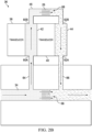
- Figs. 1A and 1B illustrated are various MFC configurations having sensor assemblies designed to include a flow through path and reservoir passages having select volumes, according to certain example embodiments.
- the overall volume of the reservoirs and the location of the flow through path in a sensor assembly depends on the type of MFC application. For low flow rate applications, a reduced reservoir volume may be needed. For high flow rate applications, an increased reservoir volume may be needed. However, the volume of the reservoir can also be based on a bleed down time. In addition, each reservoir in a sensor assembly can have a unique volume size.
- MFC configuration 10A includes a valve assembly 12A, a base having a primary flow path 14A with a primary flow path blockage 28A disposed therein, and a sensor assembly 16A.
- the sensor assembly 16A comprises two absolute pressure transducers 18A, 20A, reservoirs 22A, 24A, at least one flow through path 26A, and a characterized restrictor, not illustrated.
- MFC configuration 10B includes a valve assembly 12B, a base having a primary flow path 14B and a characterized restrictor 28B disposed therein, and a sensor assembly 16B.
- the sensor assembly 16B comprises two absolute pressure transducers 18B, 20B, reservoirs 22B, 24B, at least one flow through path 26B, and a characterized restrictor, not illustrated.
- MFC configuration 10A is configured to process fluid at lower flow rates, e.g. 0.15 sccm to 500 sccm (standard cubic centimeters per minute). The specific sccm is dependent on the specifics of gas velocity and target pressure drop across the restrictor and can change depending on the specific design and application.
- MFC configuration 10B is configured to process fluids at higher flow rates, e.g. greater than 500 sccm.
- the restrictors that are not illustrated and restrictor 28B can be characterized based on a required flow rate.
- the volumes of the reservoirs 22A, 24A and 22B, 24B can be configured to have a defined volume based on the application.
- the volume for 22A can be reduced so that in response to closing of an upstream valve, e.g. when switching between gases, the bleed down time, the time it takes for the pressure in reservoir 22A to decay as its gas exits through the restrictor 26, also is reduced.
- the bleed down time constant is proportional to the volume reservoir divided by the full scale flow rate of the MFC. As such larger full scale MFC can have the larger reservoir volumes needed for higher flow without being adversely affected by longer bleed down times.
- a well designed bleed down time can also reduce or eliminate dead volume in the sensor assemblies 16A, 16B
- MFC configuration 30A can include a valve assembly 32A, a base having a primary flow path 34A, and a sensor assembly 36A.
- Sensor assembly 36A can comprises either two absolute pressure transducers or one absolute and one differential transducer 38A, 40A, reservoirs 42A, 44A, at least one flow through path 46A, and a restrictor, not illustrated.
- MFC configuration 30A includes a sensor assembly 36A having reservoirs 42A, 44A with a volume better suited for higher flow rate applications as the preponderance of the flow passes through the larger passage 42A-1 and a smaller portions of the flow passes though 42A-2 sweeping past the sensor face.
- MFC configuration 30B can include a valve assembly 32B, a base having a primary flow path 34B, and a sensor assembly 36B.
- the sensor assembly 36B can comprise of either two absolute pressure transducers or one absolute and one differential transducer 38B, 40B, reservoirs 42B, 44B, at least one flow through path 46B, and a restrictor, not illustrated.
- MFC configuration 30B includes a sensor assembly 36B having reservoirs 42B and 44B with a reduced volume size and, therefore, is better suited for lower flow rate applications due to bleed down issues. As illustrated, the internal diameter and, therefore, the overall volume of reservoirs 42A, 44A are greater than the volume of reservoir 42B, 44B.
- the volume of reservoirs 42A, 44A is considered an internal flow path that fluidly couples and is in series with the primary flow path 34A and that is within the structure of the sensor assembly 36A, flow from 34B is split into two parallel paths, with the preponderance of the flow continuing straight through 42A-1 while a small flow is diverted to sweep past the face of the transducer 38A via passage 42A-2.
- the flows in 42A-1 and 42A-2 join at the entrance of passage of passage 46A, passes through the characterized restrictor and exits to passage 44A where flow is again split into parallel paths 44A-1 and 44A-2, with 44A-2 being diverted to sweep across the sensor face and rejoins 44A-1 exiting to the main flow path in the MFC base 34B.
- the lower flow rates do not require a splitting of the flow paths 42B and 44B and the entire flow sweeps past the faces of sensors 38B and 40B.
- the flow rate is low enough that the entire flow can be routed past the sensor face without introducing velocity related problems.
- any of the primary flow path 14 can have a characterized flow restrictor disposed therein.
- the sensor assemblies 16 and 36 can include a combination of absolute and differential pressure transducers.
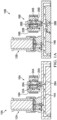
- the pressure transducers 18, 20, 38, and 44 described herein, in practice can comprises a semiconductor based transducer, an oil bath, and isolation diaphragm, wherein fluid traversing the diaphragm produces a force on the diaphragm that is transferred through the oil bath and to the transducer for measurement.
- the sensor assembly 16 includes pressure transducers 18 and 20.
- the transducers 18 and 20 are absolute pressure transducers.
- Reservoirs 22, 24 include ports 60, 62 for receiving fluid through a sampled flow path 64, 66, sampled from the primary flow path 14.
- the flow through path 26 is disposed between the reservoirs 22, 24 and a characterized restrictor 68 is disposed therein.
- the sensor assembly 36 includes pressure transducers 38, 40, flow through path 46, and ports 60A-B, 62A-B.
- the pressure transducers 38, 40 are either an absolute pressure 18 transducer and a differential pressure transducer 40 or two absolute transducers with the pressure sensing face of 40 facing 44.
- Flow through path 46 fluidly couples port 60B on one end of reservoir 42 with another port 62B on another end of reservoir 44.
- the characterized restrictor 68 is disposed within the flow through path 46.
- a characterized restrictor 70 is disposed within the primary flow paths 14, 34 and carries the bulk of the flow. In Figs. 2C and 2D , however, the primary flow paths 14, 34 do not include restrictor 70. In certain applications, both restrictors 68 and 70 are not required. In MFC applications where lower flow rates do not create gas velocity issues, restrictor 70 is not required.
- the upstream portion of the primary flow path 14, 34 continues through the sampled flow path 64, the flow through path 26, 46, the sampled flow path 66, and back to the downstream portion of the primary flow path 14, 34.
- Restrictor 68 in this case can be characterized as needed for the particular application.
- Sampled flow path 64, 66 as used in this specification, relates to a flow path carrying fluid to be measured and that is fluid communications with the pressure transducer 38, 40, and traverses the transducer port 60, 62.
- the sensors assemblies 16, 36 are described with certain transducer configurations, it should be understand that other configurations are also possible.
Landscapes
- Physics & Mathematics (AREA)
- General Physics & Mathematics (AREA)
- Fluid Mechanics (AREA)
- Chemical & Material Sciences (AREA)
- Engineering & Computer Science (AREA)
- Mechanical Engineering (AREA)
- Chemical Kinetics & Catalysis (AREA)
- Materials Engineering (AREA)
- General Chemical & Material Sciences (AREA)
- Metallurgy (AREA)
- Organic Chemistry (AREA)
- Automation & Control Theory (AREA)
- Aviation & Aerospace Engineering (AREA)
- Acoustics & Sound (AREA)
- Measuring Volume Flow (AREA)
- Flow Control (AREA)
Applications Claiming Priority (1)
| Application Number | Priority Date | Filing Date | Title |
|---|---|---|---|
| US16/852,090 US12181328B2 (en) | 2020-04-17 | 2020-04-17 | Flow through pressure sensor structured to remove dead volume |
Publications (2)
| Publication Number | Publication Date |
|---|---|
| EP3896402A1 EP3896402A1 (en) | 2021-10-20 |
| EP3896402B1 true EP3896402B1 (en) | 2024-01-24 |
Family
ID=72234657
Family Applications (1)
| Application Number | Title | Priority Date | Filing Date |
|---|---|---|---|
| EP20192300.0A Active EP3896402B1 (en) | 2020-04-17 | 2020-08-24 | Flow through pressure sensor |
Country Status (6)
| Country | Link |
|---|---|
| US (2) | US12181328B2 (https=) |
| EP (1) | EP3896402B1 (https=) |
| JP (2) | JP2021173744A (https=) |
| KR (1) | KR20210128886A (https=) |
| CN (1) | CN113532725A (https=) |
| TW (1) | TWI889697B (https=) |
Families Citing this family (1)
| Publication number | Priority date | Publication date | Assignee | Title |
|---|---|---|---|---|
| DE102024110339A1 (de) * | 2024-04-12 | 2025-10-16 | Festo Se & Co. Kg | Massenstromregelventil zur Inertgasversorgung eines Waferbehälters |
Family Cites Families (17)
| Publication number | Priority date | Publication date | Assignee | Title |
|---|---|---|---|---|
| DE2919192A1 (de) | 1978-05-26 | 1979-11-29 | Sperry Rand Corp | Durchflussmesseinrichtung |
| US6119710A (en) * | 1999-05-26 | 2000-09-19 | Cyber Instrument Technologies Llc | Method for wide range gas flow system with real time flow measurement and correction |
| US6539968B1 (en) * | 2000-09-20 | 2003-04-01 | Fugasity Corporation | Fluid flow controller and method of operation |
| EP1442343B1 (en) | 2001-10-12 | 2008-05-14 | Horiba Stec, Inc. | System and method for making and using a mass flow device |
| JP3845615B2 (ja) | 2002-03-12 | 2006-11-15 | アドバンス電気工業株式会社 | 流量センサー |
| WO2006004674A2 (en) | 2004-06-25 | 2006-01-12 | Rivatek Incorporated | Software correction method and apparatus for a variable orifice flow meter |
| EP2122389A1 (en) * | 2007-02-21 | 2009-11-25 | Sensotech, Inc. | Fluid level measuring method and system therefor |
| WO2012064809A1 (en) * | 2010-11-12 | 2012-05-18 | Siemens Healthcare Diagnostics Inc. | Real time measurements of fluid volume and flow rate using two pressure transducers |
| US9958302B2 (en) * | 2011-08-20 | 2018-05-01 | Reno Technologies, Inc. | Flow control system, method, and apparatus |
| US9188989B1 (en) * | 2011-08-20 | 2015-11-17 | Daniel T. Mudd | Flow node to deliver process gas using a remote pressure measurement device |
| CN104813095B (zh) * | 2012-09-21 | 2018-05-01 | 恩特格里斯公司 | 压力调节流体贮存和输送容器的抗尖峰压力管理 |
| SG11201600458RA (en) * | 2013-07-23 | 2016-02-26 | Entegris Inc | Remote delivery of chemical reagents |
| JP6522624B2 (ja) * | 2013-09-06 | 2019-05-29 | イリノイ トゥール ワークス インコーポレイティド | 絶対圧差圧圧力トランスデューサー |
| EP3289319B1 (en) * | 2015-04-30 | 2021-12-29 | Services Pétroliers Schlumberger | Multiphase flow meters and related methods |
| US10655989B2 (en) | 2017-09-12 | 2020-05-19 | Silicon Microstructures, Inc. | Pressure sensor cap having flow path with dimension variation |
| CN207779957U (zh) * | 2017-12-11 | 2018-08-28 | 重庆晓微城企业孵化器有限公司 | 一种用于生物电池传感器的阳极组件 |
| US10890474B2 (en) * | 2018-09-18 | 2021-01-12 | Swagelok Company | Fluid monitoring module arrangements |
-
2020
- 2020-04-17 US US16/852,090 patent/US12181328B2/en active Active
- 2020-08-13 TW TW109127488A patent/TWI889697B/zh active
- 2020-08-24 EP EP20192300.0A patent/EP3896402B1/en active Active
- 2020-08-26 JP JP2020142395A patent/JP2021173744A/ja active Pending
- 2020-08-28 CN CN202010887417.XA patent/CN113532725A/zh active Pending
- 2020-08-28 KR KR1020200109676A patent/KR20210128886A/ko active Pending
-
2024
- 2024-12-05 US US18/970,161 patent/US20250207963A1/en active Pending
-
2025
- 2025-06-18 JP JP2025102626A patent/JP2025134849A/ja active Pending
Also Published As
| Publication number | Publication date |
|---|---|
| US20250207963A1 (en) | 2025-06-26 |
| US12181328B2 (en) | 2024-12-31 |
| KR20210128886A (ko) | 2021-10-27 |
| CN113532725A (zh) | 2021-10-22 |
| US20210325223A1 (en) | 2021-10-21 |
| EP3896402A1 (en) | 2021-10-20 |
| TW202140156A (zh) | 2021-11-01 |
| JP2025134849A (ja) | 2025-09-17 |
| JP2021173744A (ja) | 2021-11-01 |
| TWI889697B (zh) | 2025-07-11 |
Similar Documents
| Publication | Publication Date | Title |
|---|---|---|
| CN100475327C (zh) | 基板处理装置 | |
| KR100539042B1 (ko) | 반도체 장치의 제조 장치 및 제조 방법, 및 반도체 제조장치의 클리닝 방법 | |
| CN110073181B (zh) | 用于大范围质量流量检验的方法和设备 | |
| KR101076833B1 (ko) | 인-시츄 흐름 검증 및 교정을 위한 시스템 및 방법 | |
| US20250207963A1 (en) | Flow Through Pressure Sensor | |
| US9127361B2 (en) | Methods of and apparatus for controlling pressure in multiple zones of a process tool | |
| KR101887360B1 (ko) | 압력식 유량 제어 장치 | |
| TW201930833A (zh) | 求氣體之流量的方法 | |
| KR102619304B1 (ko) | 가스 분석을 위한 국소 환경의 생성 | |
| KR102778742B1 (ko) | 복수의 챔버 압력 센서를 교정하는 방법 및 기판 처리 시스템 | |
| CN113113332A (zh) | 半导体工艺腔漏的侦测方法 | |
| KR20060042741A (ko) | 상압 공정에 이용되는 가스 반응 분석 장치를 위한 샘플가스 공급 시스템 | |
| JP2022078387A (ja) | ガス分析装置およびガスサンプリング装置 | |
| US12480854B1 (en) | Device and method for determining gas diffusion coefficient in rocks | |
| KR100508488B1 (ko) | 열량형 질량유량 측정센서 및 그의 오차보정 방법 | |
| EP3374759B1 (en) | Gaz analyzer with protection for optical components | |
| CN111896677A (zh) | 一种痕量气体分析装置以及方法 | |
| KR19980038304A (ko) | 반도체 제조용 진공 장치 | |
| KR20230001489A (ko) | 가스 배출 장치 | |
| JPH03118441A (ja) | 試料ガスの分析方法 | |
| TWM516717U (zh) | 晶舟盒微汙染檢測設備 | |
| JP2019020244A (ja) | 流体測定装置、流体制御システム及び制御プログラム |
Legal Events
| Date | Code | Title | Description |
|---|---|---|---|
| PUAI | Public reference made under article 153(3) epc to a published international application that has entered the european phase |
Free format text: ORIGINAL CODE: 0009012 |
|
| STAA | Information on the status of an ep patent application or granted ep patent |
Free format text: STATUS: THE APPLICATION HAS BEEN PUBLISHED |
|
| AK | Designated contracting states |
Kind code of ref document: A1 Designated state(s): AL AT BE BG CH CY CZ DE DK EE ES FI FR GB GR HR HU IE IS IT LI LT LU LV MC MK MT NL NO PL PT RO RS SE SI SK SM TR |
|
| B565 | Issuance of search results under rule 164(2) epc |
Effective date: 20210409 |
|
| STAA | Information on the status of an ep patent application or granted ep patent |
Free format text: STATUS: REQUEST FOR EXAMINATION WAS MADE |
|
| 17P | Request for examination filed |
Effective date: 20220414 |
|
| RBV | Designated contracting states (corrected) |
Designated state(s): AL AT BE BG CH CY CZ DE DK EE ES FI FR GB GR HR HU IE IS IT LI LT LU LV MC MK MT NL NO PL PT RO RS SE SI SK SM TR |
|
| REG | Reference to a national code |
Ref legal event code: R079 Ipc: G05D0007060000 Ref country code: DE Ref legal event code: R079 Ref document number: 602020024729 Country of ref document: DE Free format text: PREVIOUS MAIN CLASS: G01F0001360000 Ipc: G05D0007060000 |
|
| RIC1 | Information provided on ipc code assigned before grant |
Ipc: G01F 15/12 20060101ALI20230731BHEP Ipc: G01F 15/00 20060101ALI20230731BHEP Ipc: G01F 1/50 20060101ALI20230731BHEP Ipc: G01F 1/40 20060101ALI20230731BHEP Ipc: G01F 1/36 20060101ALI20230731BHEP Ipc: G05D 7/06 20060101AFI20230731BHEP |
|
| GRAP | Despatch of communication of intention to grant a patent |
Free format text: ORIGINAL CODE: EPIDOSNIGR1 |
|
| STAA | Information on the status of an ep patent application or granted ep patent |
Free format text: STATUS: GRANT OF PATENT IS INTENDED |
|
| INTG | Intention to grant announced |
Effective date: 20230914 |
|
| RAP3 | Party data changed (applicant data changed or rights of an application transferred) |
Owner name: ILLINOIS TOOL WORKS INC. |
|
| GRAS | Grant fee paid |
Free format text: ORIGINAL CODE: EPIDOSNIGR3 |
|
| GRAA | (expected) grant |
Free format text: ORIGINAL CODE: 0009210 |
|
| STAA | Information on the status of an ep patent application or granted ep patent |
Free format text: STATUS: THE PATENT HAS BEEN GRANTED |
|
| AK | Designated contracting states |
Kind code of ref document: B1 Designated state(s): AL AT BE BG CH CY CZ DE DK EE ES FI FR GB GR HR HU IE IS IT LI LT LU LV MC MK MT NL NO PL PT RO RS SE SI SK SM TR |
|
| REG | Reference to a national code |
Ref country code: GB Ref legal event code: FG4D |
|
| REG | Reference to a national code |
Ref country code: CH Ref legal event code: EP |
|
| REG | Reference to a national code |
Ref country code: DE Ref legal event code: R096 Ref document number: 602020024729 Country of ref document: DE |
|
| P01 | Opt-out of the competence of the unified patent court (upc) registered |
Effective date: 20240104 |
|
| REG | Reference to a national code |
Ref country code: IE Ref legal event code: FG4D |
|
| REG | Reference to a national code |
Ref country code: NL Ref legal event code: FP |
|
| REG | Reference to a national code |
Ref country code: LT Ref legal event code: MG9D |
|
| PG25 | Lapsed in a contracting state [announced via postgrant information from national office to epo] |
Ref country code: IS Free format text: LAPSE BECAUSE OF FAILURE TO SUBMIT A TRANSLATION OF THE DESCRIPTION OR TO PAY THE FEE WITHIN THE PRESCRIBED TIME-LIMIT Effective date: 20240524 |
|
| PG25 | Lapsed in a contracting state [announced via postgrant information from national office to epo] |
Ref country code: LT Free format text: LAPSE BECAUSE OF FAILURE TO SUBMIT A TRANSLATION OF THE DESCRIPTION OR TO PAY THE FEE WITHIN THE PRESCRIBED TIME-LIMIT Effective date: 20240124 |
|
| PG25 | Lapsed in a contracting state [announced via postgrant information from national office to epo] |
Ref country code: GR Free format text: LAPSE BECAUSE OF FAILURE TO SUBMIT A TRANSLATION OF THE DESCRIPTION OR TO PAY THE FEE WITHIN THE PRESCRIBED TIME-LIMIT Effective date: 20240425 |
|
| REG | Reference to a national code |
Ref country code: AT Ref legal event code: MK05 Ref document number: 1652668 Country of ref document: AT Kind code of ref document: T Effective date: 20240124 |
|
| PG25 | Lapsed in a contracting state [announced via postgrant information from national office to epo] |
Ref country code: HR Free format text: LAPSE BECAUSE OF FAILURE TO SUBMIT A TRANSLATION OF THE DESCRIPTION OR TO PAY THE FEE WITHIN THE PRESCRIBED TIME-LIMIT Effective date: 20240124 Ref country code: RS Free format text: LAPSE BECAUSE OF FAILURE TO SUBMIT A TRANSLATION OF THE DESCRIPTION OR TO PAY THE FEE WITHIN THE PRESCRIBED TIME-LIMIT Effective date: 20240424 |
|
| PG25 | Lapsed in a contracting state [announced via postgrant information from national office to epo] |
Ref country code: ES Free format text: LAPSE BECAUSE OF FAILURE TO SUBMIT A TRANSLATION OF THE DESCRIPTION OR TO PAY THE FEE WITHIN THE PRESCRIBED TIME-LIMIT Effective date: 20240124 |
|
| PG25 | Lapsed in a contracting state [announced via postgrant information from national office to epo] |
Ref country code: AT Free format text: LAPSE BECAUSE OF FAILURE TO SUBMIT A TRANSLATION OF THE DESCRIPTION OR TO PAY THE FEE WITHIN THE PRESCRIBED TIME-LIMIT Effective date: 20240124 |
|
| PG25 | Lapsed in a contracting state [announced via postgrant information from national office to epo] |
Ref country code: RS Free format text: LAPSE BECAUSE OF FAILURE TO SUBMIT A TRANSLATION OF THE DESCRIPTION OR TO PAY THE FEE WITHIN THE PRESCRIBED TIME-LIMIT Effective date: 20240424 Ref country code: NO Free format text: LAPSE BECAUSE OF FAILURE TO SUBMIT A TRANSLATION OF THE DESCRIPTION OR TO PAY THE FEE WITHIN THE PRESCRIBED TIME-LIMIT Effective date: 20240424 Ref country code: LT Free format text: LAPSE BECAUSE OF FAILURE TO SUBMIT A TRANSLATION OF THE DESCRIPTION OR TO PAY THE FEE WITHIN THE PRESCRIBED TIME-LIMIT Effective date: 20240124 Ref country code: IS Free format text: LAPSE BECAUSE OF FAILURE TO SUBMIT A TRANSLATION OF THE DESCRIPTION OR TO PAY THE FEE WITHIN THE PRESCRIBED TIME-LIMIT Effective date: 20240524 Ref country code: HR Free format text: LAPSE BECAUSE OF FAILURE TO SUBMIT A TRANSLATION OF THE DESCRIPTION OR TO PAY THE FEE WITHIN THE PRESCRIBED TIME-LIMIT Effective date: 20240124 Ref country code: GR Free format text: LAPSE BECAUSE OF FAILURE TO SUBMIT A TRANSLATION OF THE DESCRIPTION OR TO PAY THE FEE WITHIN THE PRESCRIBED TIME-LIMIT Effective date: 20240425 Ref country code: FI Free format text: LAPSE BECAUSE OF FAILURE TO SUBMIT A TRANSLATION OF THE DESCRIPTION OR TO PAY THE FEE WITHIN THE PRESCRIBED TIME-LIMIT Effective date: 20240124 Ref country code: ES Free format text: LAPSE BECAUSE OF FAILURE TO SUBMIT A TRANSLATION OF THE DESCRIPTION OR TO PAY THE FEE WITHIN THE PRESCRIBED TIME-LIMIT Effective date: 20240124 Ref country code: BG Free format text: LAPSE BECAUSE OF FAILURE TO SUBMIT A TRANSLATION OF THE DESCRIPTION OR TO PAY THE FEE WITHIN THE PRESCRIBED TIME-LIMIT Effective date: 20240124 Ref country code: AT Free format text: LAPSE BECAUSE OF FAILURE TO SUBMIT A TRANSLATION OF THE DESCRIPTION OR TO PAY THE FEE WITHIN THE PRESCRIBED TIME-LIMIT Effective date: 20240124 |
|
| PG25 | Lapsed in a contracting state [announced via postgrant information from national office to epo] |
Ref country code: PT Free format text: LAPSE BECAUSE OF FAILURE TO SUBMIT A TRANSLATION OF THE DESCRIPTION OR TO PAY THE FEE WITHIN THE PRESCRIBED TIME-LIMIT Effective date: 20240524 Ref country code: PL Free format text: LAPSE BECAUSE OF FAILURE TO SUBMIT A TRANSLATION OF THE DESCRIPTION OR TO PAY THE FEE WITHIN THE PRESCRIBED TIME-LIMIT Effective date: 20240124 |
|
| PG25 | Lapsed in a contracting state [announced via postgrant information from national office to epo] |
Ref country code: SE Free format text: LAPSE BECAUSE OF FAILURE TO SUBMIT A TRANSLATION OF THE DESCRIPTION OR TO PAY THE FEE WITHIN THE PRESCRIBED TIME-LIMIT Effective date: 20240124 Ref country code: PT Free format text: LAPSE BECAUSE OF FAILURE TO SUBMIT A TRANSLATION OF THE DESCRIPTION OR TO PAY THE FEE WITHIN THE PRESCRIBED TIME-LIMIT Effective date: 20240524 Ref country code: PL Free format text: LAPSE BECAUSE OF FAILURE TO SUBMIT A TRANSLATION OF THE DESCRIPTION OR TO PAY THE FEE WITHIN THE PRESCRIBED TIME-LIMIT Effective date: 20240124 Ref country code: LV Free format text: LAPSE BECAUSE OF FAILURE TO SUBMIT A TRANSLATION OF THE DESCRIPTION OR TO PAY THE FEE WITHIN THE PRESCRIBED TIME-LIMIT Effective date: 20240124 |
|
| PG25 | Lapsed in a contracting state [announced via postgrant information from national office to epo] |
Ref country code: DK Free format text: LAPSE BECAUSE OF FAILURE TO SUBMIT A TRANSLATION OF THE DESCRIPTION OR TO PAY THE FEE WITHIN THE PRESCRIBED TIME-LIMIT Effective date: 20240124 |
|
| PG25 | Lapsed in a contracting state [announced via postgrant information from national office to epo] |
Ref country code: SM Free format text: LAPSE BECAUSE OF FAILURE TO SUBMIT A TRANSLATION OF THE DESCRIPTION OR TO PAY THE FEE WITHIN THE PRESCRIBED TIME-LIMIT Effective date: 20240124 |
|
| PG25 | Lapsed in a contracting state [announced via postgrant information from national office to epo] |
Ref country code: CZ Free format text: LAPSE BECAUSE OF FAILURE TO SUBMIT A TRANSLATION OF THE DESCRIPTION OR TO PAY THE FEE WITHIN THE PRESCRIBED TIME-LIMIT Effective date: 20240124 Ref country code: EE Free format text: LAPSE BECAUSE OF FAILURE TO SUBMIT A TRANSLATION OF THE DESCRIPTION OR TO PAY THE FEE WITHIN THE PRESCRIBED TIME-LIMIT Effective date: 20240124 |
|
| REG | Reference to a national code |
Ref country code: DE Ref legal event code: R097 Ref document number: 602020024729 Country of ref document: DE |
|
| PG25 | Lapsed in a contracting state [announced via postgrant information from national office to epo] |
Ref country code: SK Free format text: LAPSE BECAUSE OF FAILURE TO SUBMIT A TRANSLATION OF THE DESCRIPTION OR TO PAY THE FEE WITHIN THE PRESCRIBED TIME-LIMIT Effective date: 20240124 |
|
| PG25 | Lapsed in a contracting state [announced via postgrant information from national office to epo] |
Ref country code: SM Free format text: LAPSE BECAUSE OF FAILURE TO SUBMIT A TRANSLATION OF THE DESCRIPTION OR TO PAY THE FEE WITHIN THE PRESCRIBED TIME-LIMIT Effective date: 20240124 Ref country code: SK Free format text: LAPSE BECAUSE OF FAILURE TO SUBMIT A TRANSLATION OF THE DESCRIPTION OR TO PAY THE FEE WITHIN THE PRESCRIBED TIME-LIMIT Effective date: 20240124 Ref country code: EE Free format text: LAPSE BECAUSE OF FAILURE TO SUBMIT A TRANSLATION OF THE DESCRIPTION OR TO PAY THE FEE WITHIN THE PRESCRIBED TIME-LIMIT Effective date: 20240124 Ref country code: DK Free format text: LAPSE BECAUSE OF FAILURE TO SUBMIT A TRANSLATION OF THE DESCRIPTION OR TO PAY THE FEE WITHIN THE PRESCRIBED TIME-LIMIT Effective date: 20240124 Ref country code: CZ Free format text: LAPSE BECAUSE OF FAILURE TO SUBMIT A TRANSLATION OF THE DESCRIPTION OR TO PAY THE FEE WITHIN THE PRESCRIBED TIME-LIMIT Effective date: 20240124 |
|
| PLBE | No opposition filed within time limit |
Free format text: ORIGINAL CODE: 0009261 |
|
| STAA | Information on the status of an ep patent application or granted ep patent |
Free format text: STATUS: NO OPPOSITION FILED WITHIN TIME LIMIT |
|
| PG25 | Lapsed in a contracting state [announced via postgrant information from national office to epo] |
Ref country code: IT Free format text: LAPSE BECAUSE OF FAILURE TO SUBMIT A TRANSLATION OF THE DESCRIPTION OR TO PAY THE FEE WITHIN THE PRESCRIBED TIME-LIMIT Effective date: 20240124 |
|
| PG25 | Lapsed in a contracting state [announced via postgrant information from national office to epo] |
Ref country code: IT Free format text: LAPSE BECAUSE OF FAILURE TO SUBMIT A TRANSLATION OF THE DESCRIPTION OR TO PAY THE FEE WITHIN THE PRESCRIBED TIME-LIMIT Effective date: 20240124 |
|
| 26N | No opposition filed |
Effective date: 20241025 |
|
| REG | Reference to a national code |
Ref country code: CH Ref legal event code: PL |
|
| PG25 | Lapsed in a contracting state [announced via postgrant information from national office to epo] |
Ref country code: LU Free format text: LAPSE BECAUSE OF NON-PAYMENT OF DUE FEES Effective date: 20240824 |
|
| PG25 | Lapsed in a contracting state [announced via postgrant information from national office to epo] |
Ref country code: CH Free format text: LAPSE BECAUSE OF NON-PAYMENT OF DUE FEES Effective date: 20240831 Ref country code: SI Free format text: LAPSE BECAUSE OF FAILURE TO SUBMIT A TRANSLATION OF THE DESCRIPTION OR TO PAY THE FEE WITHIN THE PRESCRIBED TIME-LIMIT Effective date: 20240124 Ref country code: MC Free format text: LAPSE BECAUSE OF FAILURE TO SUBMIT A TRANSLATION OF THE DESCRIPTION OR TO PAY THE FEE WITHIN THE PRESCRIBED TIME-LIMIT Effective date: 20240124 |
|
| REG | Reference to a national code |
Ref country code: BE Ref legal event code: MM Effective date: 20240831 |
|
| PG25 | Lapsed in a contracting state [announced via postgrant information from national office to epo] |
Ref country code: BE Free format text: LAPSE BECAUSE OF NON-PAYMENT OF DUE FEES Effective date: 20240831 |
|
| PG25 | Lapsed in a contracting state [announced via postgrant information from national office to epo] |
Ref country code: FR Free format text: LAPSE BECAUSE OF NON-PAYMENT OF DUE FEES Effective date: 20240831 |
|
| PG25 | Lapsed in a contracting state [announced via postgrant information from national office to epo] |
Ref country code: IE Free format text: LAPSE BECAUSE OF NON-PAYMENT OF DUE FEES Effective date: 20240824 |
|
| PGFP | Annual fee paid to national office [announced via postgrant information from national office to epo] |
Ref country code: NL Payment date: 20250826 Year of fee payment: 6 |
|
| PGFP | Annual fee paid to national office [announced via postgrant information from national office to epo] |
Ref country code: DE Payment date: 20250827 Year of fee payment: 6 |
|
| PGFP | Annual fee paid to national office [announced via postgrant information from national office to epo] |
Ref country code: GB Payment date: 20250827 Year of fee payment: 6 |
|
| PG25 | Lapsed in a contracting state [announced via postgrant information from national office to epo] |
Ref country code: RO Free format text: LAPSE BECAUSE OF FAILURE TO SUBMIT A TRANSLATION OF THE DESCRIPTION OR TO PAY THE FEE WITHIN THE PRESCRIBED TIME-LIMIT Effective date: 20240124 |
|
| PG25 | Lapsed in a contracting state [announced via postgrant information from national office to epo] |
Ref country code: CY Free format text: LAPSE BECAUSE OF FAILURE TO SUBMIT A TRANSLATION OF THE DESCRIPTION OR TO PAY THE FEE WITHIN THE PRESCRIBED TIME-LIMIT; INVALID AB INITIO Effective date: 20200824 |
|
| PG25 | Lapsed in a contracting state [announced via postgrant information from national office to epo] |
Ref country code: HU Free format text: LAPSE BECAUSE OF FAILURE TO SUBMIT A TRANSLATION OF THE DESCRIPTION OR TO PAY THE FEE WITHIN THE PRESCRIBED TIME-LIMIT; INVALID AB INITIO Effective date: 20200824 |