EP3896312A1 - Hydraulic assembly for a vehicle transmission - Google Patents
Hydraulic assembly for a vehicle transmission Download PDFInfo
- Publication number
- EP3896312A1 EP3896312A1 EP21161029.0A EP21161029A EP3896312A1 EP 3896312 A1 EP3896312 A1 EP 3896312A1 EP 21161029 A EP21161029 A EP 21161029A EP 3896312 A1 EP3896312 A1 EP 3896312A1
- Authority
- EP
- European Patent Office
- Prior art keywords
- hydraulic
- control valve
- pump
- system pressure
- switching position
- Prior art date
- Legal status (The legal status is an assumption and is not a legal conclusion. Google has not performed a legal analysis and makes no representation as to the accuracy of the status listed.)
- Granted
Links
- 230000005540 biological transmission Effects 0.000 title claims abstract description 16
- 238000005461 lubrication Methods 0.000 claims abstract description 28
- 230000000630 rising effect Effects 0.000 claims description 2
- 238000010586 diagram Methods 0.000 description 5
- 239000012528 membrane Substances 0.000 description 2
- 238000000034 method Methods 0.000 description 2
- 238000010276 construction Methods 0.000 description 1
- 238000006073 displacement reaction Methods 0.000 description 1
- 230000003993 interaction Effects 0.000 description 1
- 230000006641 stabilisation Effects 0.000 description 1
- 238000011105 stabilization Methods 0.000 description 1
Images


Classifications
-
- F—MECHANICAL ENGINEERING; LIGHTING; HEATING; WEAPONS; BLASTING
- F16—ENGINEERING ELEMENTS AND UNITS; GENERAL MEASURES FOR PRODUCING AND MAINTAINING EFFECTIVE FUNCTIONING OF MACHINES OR INSTALLATIONS; THERMAL INSULATION IN GENERAL
- F16H—GEARING
- F16H61/00—Control functions within control units of change-speed- or reversing-gearings for conveying rotary motion ; Control of exclusively fluid gearing, friction gearing, gearings with endless flexible members or other particular types of gearing
- F16H61/0021—Generation or control of line pressure
-
- F—MECHANICAL ENGINEERING; LIGHTING; HEATING; WEAPONS; BLASTING
- F15—FLUID-PRESSURE ACTUATORS; HYDRAULICS OR PNEUMATICS IN GENERAL
- F15B—SYSTEMS ACTING BY MEANS OF FLUIDS IN GENERAL; FLUID-PRESSURE ACTUATORS, e.g. SERVOMOTORS; DETAILS OF FLUID-PRESSURE SYSTEMS, NOT OTHERWISE PROVIDED FOR
- F15B13/00—Details of servomotor systems ; Valves for servomotor systems
- F15B13/02—Fluid distribution or supply devices characterised by their adaptation to the control of servomotors
- F15B13/04—Fluid distribution or supply devices characterised by their adaptation to the control of servomotors for use with a single servomotor
- F15B13/042—Fluid distribution or supply devices characterised by their adaptation to the control of servomotors for use with a single servomotor operated by fluid pressure
-
- F—MECHANICAL ENGINEERING; LIGHTING; HEATING; WEAPONS; BLASTING
- F16—ENGINEERING ELEMENTS AND UNITS; GENERAL MEASURES FOR PRODUCING AND MAINTAINING EFFECTIVE FUNCTIONING OF MACHINES OR INSTALLATIONS; THERMAL INSULATION IN GENERAL
- F16H—GEARING
- F16H57/00—General details of gearing
- F16H57/04—Features relating to lubrication or cooling or heating
- F16H57/0434—Features relating to lubrication or cooling or heating relating to lubrication supply, e.g. pumps ; Pressure control
- F16H57/0435—Pressure control for supplying lubricant; Circuits or valves therefor
-
- F—MECHANICAL ENGINEERING; LIGHTING; HEATING; WEAPONS; BLASTING
- F16—ENGINEERING ELEMENTS AND UNITS; GENERAL MEASURES FOR PRODUCING AND MAINTAINING EFFECTIVE FUNCTIONING OF MACHINES OR INSTALLATIONS; THERMAL INSULATION IN GENERAL
- F16H—GEARING
- F16H57/00—General details of gearing
- F16H57/04—Features relating to lubrication or cooling or heating
- F16H57/0434—Features relating to lubrication or cooling or heating relating to lubrication supply, e.g. pumps ; Pressure control
- F16H57/0446—Features relating to lubrication or cooling or heating relating to lubrication supply, e.g. pumps ; Pressure control the supply forming part of the transmission control unit, e.g. for automatic transmissions
-
- F—MECHANICAL ENGINEERING; LIGHTING; HEATING; WEAPONS; BLASTING
- F16—ENGINEERING ELEMENTS AND UNITS; GENERAL MEASURES FOR PRODUCING AND MAINTAINING EFFECTIVE FUNCTIONING OF MACHINES OR INSTALLATIONS; THERMAL INSULATION IN GENERAL
- F16K—VALVES; TAPS; COCKS; ACTUATING-FLOATS; DEVICES FOR VENTING OR AERATING
- F16K11/00—Multiple-way valves, e.g. mixing valves; Pipe fittings incorporating such valves
- F16K11/10—Multiple-way valves, e.g. mixing valves; Pipe fittings incorporating such valves with two or more closure members not moving as a unit
- F16K11/105—Three-way check or safety valves with two or more closure members
-
- F—MECHANICAL ENGINEERING; LIGHTING; HEATING; WEAPONS; BLASTING
- F16—ENGINEERING ELEMENTS AND UNITS; GENERAL MEASURES FOR PRODUCING AND MAINTAINING EFFECTIVE FUNCTIONING OF MACHINES OR INSTALLATIONS; THERMAL INSULATION IN GENERAL
- F16K—VALVES; TAPS; COCKS; ACTUATING-FLOATS; DEVICES FOR VENTING OR AERATING
- F16K17/00—Safety valves; Equalising valves, e.g. pressure relief valves
- F16K17/02—Safety valves; Equalising valves, e.g. pressure relief valves opening on surplus pressure on one side; closing on insufficient pressure on one side
- F16K17/04—Safety valves; Equalising valves, e.g. pressure relief valves opening on surplus pressure on one side; closing on insufficient pressure on one side spring-loaded
- F16K17/042—Safety valves; Equalising valves, e.g. pressure relief valves opening on surplus pressure on one side; closing on insufficient pressure on one side spring-loaded with locking or disconnecting arrangements
-
- F—MECHANICAL ENGINEERING; LIGHTING; HEATING; WEAPONS; BLASTING
- F16—ENGINEERING ELEMENTS AND UNITS; GENERAL MEASURES FOR PRODUCING AND MAINTAINING EFFECTIVE FUNCTIONING OF MACHINES OR INSTALLATIONS; THERMAL INSULATION IN GENERAL
- F16H—GEARING
- F16H61/00—Control functions within control units of change-speed- or reversing-gearings for conveying rotary motion ; Control of exclusively fluid gearing, friction gearing, gearings with endless flexible members or other particular types of gearing
- F16H61/0021—Generation or control of line pressure
- F16H2061/0037—Generation or control of line pressure characterised by controlled fluid supply to lubrication circuits of the gearing
-
- Y—GENERAL TAGGING OF NEW TECHNOLOGICAL DEVELOPMENTS; GENERAL TAGGING OF CROSS-SECTIONAL TECHNOLOGIES SPANNING OVER SEVERAL SECTIONS OF THE IPC; TECHNICAL SUBJECTS COVERED BY FORMER USPC CROSS-REFERENCE ART COLLECTIONS [XRACs] AND DIGESTS
- Y10—TECHNICAL SUBJECTS COVERED BY FORMER USPC
- Y10T—TECHNICAL SUBJECTS COVERED BY FORMER US CLASSIFICATION
- Y10T137/00—Fluid handling
- Y10T137/8593—Systems
- Y10T137/85978—With pump
- Y10T137/85986—Pumped fluid control
- Y10T137/86002—Fluid pressure responsive
- Y10T137/8601—And pilot valve
Definitions
- the hydraulic arrangement has a hydraulic pump for providing a system pressure for a hydraulic system circuit and a lubrication pressure for a hydraulic lubrication circuit.
- the system circuit is used in particular to control or close one or more clutches within the vehicle transmission actuate.
- the lubrication circuit is used in particular for continuous lubrication of the vehicle transmission.
- a control valve is hydraulically connected between a pump outlet of the pump and the two hydraulic circuits. The control valve has at least two different switching positions in such a way that, depending on its switching position, it acts as a hydraulic connection between the pump and the system circuit or between the pump and the lubrication circuit.
- the hydraulic arrangement contains a storage unit (e.g. membrane storage tank, accumulator) which is connected to the system circuit.
- a storage unit e.g. membrane storage tank, accumulator
- a working pressure above a minimum working pressure can be maintained for the system circuit over a longer period of time without the need for the pump. This reduces the switching frequency of the control valve between its switching positions and also supports efficient operation of the hydraulic arrangement.
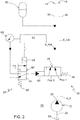
- the control valve 28 is connected between a pump outlet 32 of the pump 12 and the two hydraulic circuits 14, 16. In the initial position of the control valve 28 according to switching position Pos1 ( Fig. 1 , Fig. 2 ) the hydraulic medium is completely conveyed to the system circuit 14. In the switching position Pos2 of the control valve 28, the pump 12 conveys the hydraulic medium completely to the lubrication circuit 16.
- the control valve 28 according to Fig. 1 has a first and a second control input 34, 36, the hydraulic control pressures of which act against a return spring 38.
- FIG. 3A illustrated system behavior of the system circuit 14.
- the system pressure p_sys shows a sawtooth-like curve.
- the pump 12 is in a boost pressure mode M_d for a short period of time and otherwise in a normal operating mode M_n.
- the drive unit 26 drives the pump 12 in such a way that the latter only has to maintain the relatively low lubrication pressure p_lub.
- This solution gives the hydraulic arrangement 10 an efficiency similar to that which can be achieved with a technically more complex and costly solution with two pumps.
Landscapes
- Engineering & Computer Science (AREA)
- General Engineering & Computer Science (AREA)
- Mechanical Engineering (AREA)
- Physics & Mathematics (AREA)
- Fluid Mechanics (AREA)
- Control Of Transmission Device (AREA)
Abstract
Die Erfindung betrifft eine hydraulische Anordnung (10) für ein Fahrzeuggetriebe. Die Anordnung (10) enthält eine hydraulische Pumpe (12) zur Bereitstellung eines Systemdruckes (p_sys) für einen hydraulischen Systemkreislauf (14) und eines Schmierungsdruckes (p_lub) für einen hydraulischen Schmierungskreislauf (16). Außerdem enthält die Anordnung (10) ein Steuerventil (28), welches zwischen einem Pumpenausgang (32) der Pumpe (12) und den beiden hydraulischen Kreisläufen (14, 16) angeschlossen ist und zwei unterschiedliche Schaltstellungen (Pos1, Pos2) aufweist derart, dass das Steuerventil (28) in Abhängigkeit von seiner Schaltstellung (Po1, Pos2) als eine hydraulische Verbindung zwischen der Pumpe (12) und dem Systemkreislauf (14) oder zwischen der Pumpe (12) und dem Schmierungskreislauf (16) wirkt.The invention relates to a hydraulic arrangement (10) for a vehicle transmission. The arrangement (10) contains a hydraulic pump (12) for providing a system pressure (p_sys) for a hydraulic system circuit (14) and a lubrication pressure (p_lub) for a hydraulic lubrication circuit (16). The arrangement (10) also contains a control valve (28) which is connected between a pump outlet (32) of the pump (12) and the two hydraulic circuits (14, 16) and has two different switching positions (Pos1, Pos2) such that the control valve (28), depending on its switching position (Po1, Pos2), acts as a hydraulic connection between the pump (12) and the system circuit (14) or between the pump (12) and the lubrication circuit (16).
Description
Die Erfindung betrifft eine hydraulische Anordnung für ein Fahrzeuggetriebe.The invention relates to a hydraulic arrangement for a vehicle transmission.
Fahrzeuggetriebe benötigen ein Hydraulikmedium (z.B. Öl), um deren Kupplungen in einem hydraulischen Systemkreislauf zu steuern als auch eine ausreichende Schmierung in einem hydraulischen Schmierungskreislauf zu gewährleisten. Beide Kreisläufe haben unterschiedliche hydraulische Anforderungen. Beispielsweise erfordert der Systemkreislauf außerhalb von Schaltvorgängen eine niedrige Flussrate und während der Schaltvorgänge eine hohe Flussrate des Hydraulikmediums. Hingegen benötigt der Schmierungskreislauf vorzugsweise eine kontinuierliche hohe Flussrate bei niedrigem Druck.Vehicle transmissions require a hydraulic medium (e.g. oil) to control their clutches in a hydraulic system circuit and to ensure adequate lubrication in a hydraulic lubrication circuit. Both circuits have different hydraulic requirements. For example, the system circuit requires a low flow rate outside of switching processes and a high flow rate of the hydraulic medium during the switching processes. In contrast, the lubrication circuit preferably requires a continuous high flow rate at low pressure.
Der vorliegenden Erfindung liegt die Aufgabe zugrunde, die Effizienz der Arbeitsweise eines hydraulischen Fahrzeuggetriebes zu verbessern.The present invention is based on the object of improving the efficiency of the operation of a hydraulic vehicle transmission.
Diese Aufgabe wird durch eine hydraulische Anordnung mit den Merkmalen des Patentanspruchs 1 gelöst.This object is achieved by a hydraulic arrangement with the features of
Weitere vorteilhafte Ausgestaltungen der erfindungsgemäßen hydraulischen Anordnung gehen aus den Unteransprüchen hervor.Further advantageous configurations of the hydraulic arrangement according to the invention emerge from the subclaims.
Gemäß Patentanspruch 1 weist die hydraulische Anordnung eine hydraulische Pumpe zur Bereitstellung eines Systemdruckes für einen hydraulischen Systemkreislauf und eines Schmierungsdruckes für einen hydraulischen Schmierungskreislauf auf. Der Systemkreislauf dient insbesondere dazu, eine oder mehrere Kupplungen innerhalb des Fahrzeuggetriebes zu steuern bzw. zu betätigen. Der Schmierungskreislauf dient insbesondere einer kontinuierlichen Schmierung des Fahrzeuggetriebes. Zwischen einem Pumpenausgang der Pumpe und den beiden hydraulischen Kreisläufen ist ein Steuerventil hydraulisch angeschlossen. Dabei weist das Steuerventil mindestens zwei unterschiedliche Schaltstellungen auf derart, dass es in Abhängigkeit von seiner Schaltstellung als eine hydraulische Verbindung zwischen der Pumpe und dem Systemkreislauf oder zwischen der Pumpe und dem Schmierungskreislauf wirkt.According to
Das zwischen unterschiedlichen Schaltstellungen umschaltbare Steuerventil ermöglicht es, dass die Pumpe bedarfsgerecht entweder mit dem Systemkreislauf oder mit dem Schmierungskreislauf hydraulisch verbunden ist. Hierdurch kann das Fahrzeuggetriebe kostengünstig mit einer einzigen Pumpe und gleichzeitig effizient mit geringen Energieverlusten betrieben werden. Außerdem bleibt die technische Komplexität der hydraulischen Anordnung verhältnismäßig gering. Somit ist die technische Voraussetzung geschaffen, dass zwei hydraulische Kreisläufe trotz einer einzigen Pumpe mit einem Effizienzgrad versorgt werden können, wie er ansonsten nur mit zwei bereitgestellten hydraulischen Pumpen erreicht werden kann.The control valve, which can be switched between different switching positions, enables the pump to be hydraulically connected either to the system circuit or to the lubrication circuit as required. As a result, the vehicle transmission can be operated inexpensively with a single pump and at the same time efficiently with low energy losses. In addition, the technical complexity of the hydraulic arrangement remains relatively low. This creates the technical prerequisite that, despite a single pump, two hydraulic circuits can be supplied with a degree of efficiency that can otherwise only be achieved with two hydraulic pumps provided.
Wie bereits erwähnt, wird die hydraulische Anordnung bei einem Fahrzeuggetriebe eingesetzt. Bei der hydraulischen Pumpe handelt es sich insbesondere um eine Getriebeölpumpe. Das Fahrzeug ist insbesondere ein Nutzfahrzeug wie etwa ein landwirtschaftliches Nutzfahrzeug (z.B. Schlepper, Traktor), ein forstwirtschaftliches Nutzfahrzeug oder eine Baumaschine.As already mentioned, the hydraulic arrangement is used in a vehicle transmission. The hydraulic pump is, in particular, a transmission oil pump. The vehicle is in particular a utility vehicle such as an agricultural utility vehicle (eg tractor, tractor), a forestry utility vehicle or a construction machine.
In einer bevorzugten Ausführungsform enthält die hydraulische Anordnung eine Speichereinheit (z.B. Membranspeicher, Akkumulator), welche an den Systemkreislauf angeschlossen ist. Hierdurch kann für den Systemkreislauf über einen längeren Zeitraum hinweg ein Arbeitsdruck oberhalb eines minimalen Arbeitsdruckes aufrechterhalten werden, ohne hierzu die Pumpe zu benötigen. Dies reduziert die Umschaltfrequenz des Steuerventils zwischen seinen Schaltstellungen und unterstützt zusätzlich eine effiziente Arbeitsweise der hydraulischen Anordnung.In a preferred embodiment, the hydraulic arrangement contains a storage unit (e.g. membrane storage tank, accumulator) which is connected to the system circuit. As a result, a working pressure above a minimum working pressure can be maintained for the system circuit over a longer period of time without the need for the pump. This reduces the switching frequency of the control valve between its switching positions and also supports efficient operation of the hydraulic arrangement.
Analog kann auch an den Schmierungskreislauf eine Speichereinheit angeschlossen sein, um diesen Kreislauf hinsichtlich seines hydraulischen Druckes zu stabilisieren.Similarly, a storage unit can also be connected to the lubrication circuit in order to stabilize this circuit with regard to its hydraulic pressure.
Vorzugsweise ändert das Steuerventil seine Schaltstellung
- bei Erreichen oder Unterschreiten eines vorbestimmten minimalen Systemdruckes, und/oder
- bei Erreichen oder Überschreiten eines vorbestimmten maximalen Systemdruckes.
- when reaching or falling below a predetermined minimum system pressure, and / or
- when a predetermined maximum system pressure is reached or exceeded.
Mit den vorbestimmten Werten eines minimalen und maximalen Systemdruckes kann die Effizienz der Pumpe bei der abwechselnden hydraulischen Verbindung mit dem Systemkreislauf und mit dem Schmierungskreislauf weiter verbessert werden.With the predetermined values of a minimum and maximum system pressure, the efficiency of the pump can be further improved in the alternating hydraulic connection with the system circuit and with the lubrication circuit.
Für die abwechselnde hydraulische Verbindung der Pumpe mit den beiden hydraulischen Kreisläufen ist das Schaltschema des Steuerventils insbesondere derart definiert, dass
- das Steuerventil ausgehend von einem sinkenden Systemdruck nach Erreichen oder Unterschreiten des minimalen Systemdruckes eine erste Schaltstellung einnimmt für eine hydraulische Verbindung der Pumpe mit dem Systemkreislauf, und/oder
- das Steuerventil ausgehend von einem steigenden Systemdruck nach Erreichen oder Überschreiten des maximalen Systemdruckes eine zweite Schaltstellung einnimmt für eine hydraulische Verbindung der Pumpe mit dem Schmierungskreislauf.
- the control valve, based on a falling system pressure after reaching or falling below the minimum system pressure, assumes a first switching position for a hydraulic connection of the pump to the system circuit, and / or
- the control valve assumes a second switching position for a hydraulic connection of the pump with the lubrication circuit, based on an increasing system pressure after reaching or exceeding the maximum system pressure.
Vorzugsweise ist das Steuerventil als ein 3/2-Wegeventil mit drei Anschlüssen und zwei Schaltstellungen ausgebildet und kann hierdurch kostengünstig als Standardbauteil bereitgestellt werden.The control valve is preferably designed as a 3/2-way valve with three connections and two switching positions and can thus be provided as a standard component at low cost.
Vorteilhaft wirkt das Steuerventil in seinen unterschiedlichen Schaltstellungen mit einer Halte-Ventileinheit zusammen. Dabei ist das Steuerventil in seiner zweiten Schaltstellung insbesondere lösbar gehalten bzw. arretiert, indem die Halte-Ventileinheit eine spezifische Schaltposition einnimmt. Für ein technisch einfaches Zusammenwirken mit dem Steuerventil ist die Halte-Ventileinheit in Abhängigkeit von dem Systemdruck ansteuerbar. Hierdurch kann die lösbare Fixierung des Steuerventils in seiner zweiten Schaltstellung automatisch erzielt und auch wieder aufgehoben werden.The control valve advantageously interacts with a holding valve unit in its different switching positions. In this case, the control valve is held or locked in its second switching position, in particular, in a releasable manner, in that the holding valve unit assumes a specific switching position. For a technically simple interaction with the control valve, the holding valve unit can be controlled as a function of the system pressure. As a result, the releasable fixing of the control valve in its second switching position can be achieved automatically and also canceled again.
In einer bevorzugten Ausführungsform weist die Halte-Ventileinheit mechanische Arretiermittel auf, um das Steuerventil in seiner zweiten Schaltstellung lösbar zu arretieren. Dabei kann das Steuerventil geeignete Gegenmittel aufweisen, welche mit den vorgenannten Arretiermitteln zusammenwirken. Beispielsweise trägt die Halte-Ventileinheit einen Arretiervorsprung, welcher in eine Aussparung eines Arretierauslegers oder Arretierarmes des Steuerventils lösbar eingreift.In a preferred embodiment, the holding valve unit has mechanical locking means in order to releasably lock the control valve in its second switching position. Included the control valve can have suitable countermeasures which interact with the aforementioned locking means. For example, the holding valve unit carries a locking projection which releasably engages in a recess of a locking arm or locking arm of the control valve.
In einer weiteren bevorzugten Ausführungsform weist die Halte-Ventileinheit einen ansteuerbaren Elektromagneten auf. Der Elektromagnet wird beispielsweise von einer Steuerelektronik in Abhängigkeit von dem aktuellen Systemdruck angesteuert. Eine mittels des Elektromagneten erzielbare spezifische Schaltposition kann dann technisch stabil das Steuerventil in seiner zweiten Schaltstellung lösbar halten.In a further preferred embodiment, the holding valve unit has a controllable electromagnet. The electromagnet is activated, for example, by control electronics as a function of the current system pressure. A specific switching position that can be achieved by means of the electromagnet can then hold the control valve in its second switching position in a technically stable manner.
Die erfindungsgemäße hydraulische Anordnung wird im Folgenden anhand der beigefügten Zeichnungen näher erläutert. Dabei sind hinsichtlich ihrer Funktion übereinstimmende bzw. vergleichbare Bauteile mit denselben Bezugszeichen gekennzeichnet. Es zeigen:
- Fig. 1
- ein hydraulischer Schaltplan mit der hydraulischen Anordnung in einer ersten Ausführungsform,
- Fig. 2
- ein hydraulischer Schaltplan mit der hydraulischen Anordnung in einer zweiten Ausführungsform,
- Fig. 3A
- ein Diagramm mit einer Druck-Kennlinie des hydraulischen Systemkreislaufes, und
- Fig. 3B
- ein Diagramm mit einer Druck-Kennlinie der hydraulischen Pumpe.
- Fig. 1
- a hydraulic circuit diagram with the hydraulic arrangement in a first embodiment,
- Fig. 2
- a hydraulic circuit diagram with the hydraulic arrangement in a second embodiment,
- Figure 3A
- a diagram with a pressure characteristic of the hydraulic system circuit, and
- Figure 3B
- a diagram with a pressure characteristic of the hydraulic pump.
Die Anordnung 10 enthält eine hydraulische Pumpe 12 zum Fördern eines Hydraulikmediums (z.B. Öl) in Richtung eines hydraulischen Systemkreislaufes 14 und eines Schmierungskreislaufes 16. Der Systemkreislauf 14 ist mit einer Systemleitung 18 angedeutet und führt zu mindestens einer Kupplung des Fahrzeuggetriebes und gegebenenfalls weiteren Bauteilen des Systemkreislaufes 14. Der Schmierungskreislauf 16 ist mit einer Schmierungsleitung 20 angedeutet und dient einer kontinuierlichen Schmierung der relevanten Bauteile des Fahrzeuggetriebes.The
Die Pumpe 12 ist mit einer Saugleitung 22 an einen das Hydraulikmedium enthaltenden Hydraulikbehälter 24 bzw. Sumpf angeschlossen.The
Beispielsgemäß weist die mittels einer Antriebseinheit 26 angetriebene Pumpe 12 ein festes Verdrängungsvolumen auf. Alternativ kann es sich bei der Pumpe 12 jedoch auch um eine Verschwenkpumpe handeln, sodass einzelne Betriebsparameter (z.B. Drehzahl, Flussrate, Pumpendruck p_p) der Pumpe 12 in Abhängigkeit des aktuell zu versorgenden hydraulischen Kreislaufes 14 oder 16 selbsttätig nachgeregelt werden. Der Pumpenbetrieb wird dann bedarfsgerecht und effizienzsteigernd an die hydraulischen Erfordernisse des Systemkreislaufes und des Schmierungskreislaufes angepasst.According to the example, the
Zur Druckstabilisierung ist an den Systemkreislauf 14 eine Speichereinheit 30 (z.B. Membranspeicher, Akkumulator) hydraulisch angeschlossen. Optional ist auch an den Schmierungskreislauf 16 eine (hier nicht dargestellte) Speichereinheit hydraulisch angeschlossen.A storage unit 30 (e.g. membrane storage tank, accumulator) is hydraulically connected to the
Das Steuerventil 28 ist zwischen einem Pumpenausgang 32 der Pumpe 12 und den beiden hydraulischen Kreisläufen 14, 16 angeschlossen. In der Ausgangsstellung des Steuerventils 28 gemäß Schaltstellung Pos1 (
Der Systemdruck p_sys hat einen Bereich von einem vorbestimmten minimalen Systemdruck p_min bis zu einem vorbestimmten maximalen Systemdruck p_max. Dieser Bereich ist in
Dabei wird das Steuerventil 28 ausgehend von einem sinkenden Systemdruck p_sys nach Erreichen oder Unterschreiten des minimalen Systemdruckes p_min in seine erste Schaltstellung Pos1 umgeschaltet für eine hydraulische Verbindung der Pumpe 12 mit dem Systemkreislauf 14. Das Hydraulikmedium wird dann vollständig zur Speichereinheit 30 und zum Systemkreislauf 14 gepumpt, bis bei steigendem Systemdruck p_sys der maximale Systemdruck p_max erreicht ist. Nach Erreichen oder Überschreiten des maximalen Systemdruckes p_max nimmt das Steuerventil 28 seine zweite Schaltstellung Pos2 ein für eine hydraulische Verbindung der Pumpe 12 mit dem Schmierungskreislauf 16.Starting from a falling system pressure p_sys, the
Bei beiden Ausführungsformen gemäß
Das Steuerventil 28 gemäß
In der Schaltstellung Pos2 wird das Steuerventil 28 mittels einer Halte-Ventileinheit 40 lösbar gehalten, bis der minimale Systemdruck p_min unterschritten ist. Zu diesem Zweck weist die Halte-Ventileinheit 40 einen Steuereingang 42 auf, an dem der aktuelle Systemdruck p_sys anliegt. Gegen den Druck am Steuereingang 42 wirkt der Federdruck einer Rückstellfeder 44. Dieser Federdruck ist etwa auf den minimalen Systemdruck p_min eingestellt. Sobald der steigende aktuelle Systemdruck p_sys den Federdruck der Rückstellfeder 44 bzw. den minimalen Systemdruck p_min erreicht oder überschreitet, drückt ein Arretiervorsprung 46 der Halte-Ventileinheit 40 gegen einen Arretierarm 48 des Steuerventils 28. Erst wenn das Steuerventil 28 in seine zweite Schaltstellung Pos2 überführt wird, verrastet der Arretiervorsprung 46 mit dem Arretierarm 48. Dabei rastet der Arretiervorsprung 46 beispielsweise in eine Aussparung 50 des Arretierarmes 48 ein.In the switching position Pos2, the
Die mechanischen Arretiermittel 46, 48, 50 bewirken eine lösbare Arretierung des Steuerventils 28 in seiner zweiten Schaltstellung Pos2, bis der aktuelle Systemdruck p_sys unterhalb des minimalen Systemdruckes p_min fällt. In dieser Situation wird die Arretierung des Steuerventils 28 gelöst, so dass das Steuerventil 28 mittels des geeignet dimensionierten Federdrucks seiner Rückstellfeder 38 wieder in seine erste Schaltstellung Pos1 überführt wird, um den aktuellen Systemdruck p_sys bis zu dem vorbestimmten maximalen Systemdruck p_max aufzuladen.The mechanical locking means 46, 48, 50 cause a releasable locking of the
Damit das Steuerventil 28 ausgehend von seiner ersten Schaltstellung Pos1 in seine zweite Schaltstellung Pos2 umgeschaltet wird, ist eine weitere Ventileinheit in Form eines Hochdruck-Ventils 52 vorgesehen. Es ist als ein 3/2- Wegeventil mit drei Anschlüssen und zwei Schaltstellungen ausgebildet. An dessen Steuereingang 54 liegt der aktuelle Systemdruck p_sys an. Der Steuereingang 54 wirkt gegen den Federdruck einer Rückstellfeder 56. Dieser Federdruck ist etwa auf den maximalen Systemdruck p_max eingestellt.A further valve unit in the form of a high-
Sobald der steigende aktuelle Systemdruck p_sys den maximalen Systemdruck p_max erreicht oder überschreitet, wird das Hochdruck-Ventil 52 von seiner in
Entgegen der Darstellung in
In
Die Anordnung 10 gemäß
Die Steuerelektronik 62 ist derart ausgelegt, dass sie den Elektromagneten 58 beaufschlagt bzw. aktiviert, sobald der ansteigende aktuelle Systemdruck p_sys den maximalen Systemdruck p_max erreicht oder überschreitet. Hierdurch wird die Halte-Ventileinheit 40' in ihre Schaltposition P2 überführt. Folglich überführt der maximale Systemdruck p_max über einen Steuereingang 64 des Steuerventils 28 letzteres gegen den Federdruck der Rückstellfeder 38 in die zweite Schaltstellung Pos2. Sobald der sinkende aktuelle Systemdruck p_sys den minimalen Systemdruck p_min erreicht oder unterschreitet, deaktiviert die Steuerelektronik 62 den Elektromagneten 58. Hierdurch wird die Halte-Ventileinheit 40' durch die Rückstellfeder 66 automatisch in ihre Ausgangsstellung gemäß Schaltposition P1 zurückgeschaltet. Folglich wird das Steuerventil 28 durch seine Rückstellfeder 38 automatisch in seine erste Schaltstellung Pos1 zurückgeschaltet.The
Bei beiden Ausführungsformen gemäß
Es sei darauf hingewiesen, dass die in den Zeichnungen offenbarten Details teilweise schematisch und nicht notwendigerweise maßstabsgetreu dargestellt sind.It should be noted that the details disclosed in the drawings are partly shown schematically and not necessarily true to scale.
Claims (8)
Applications Claiming Priority (1)
| Application Number | Priority Date | Filing Date | Title |
|---|---|---|---|
| DE102020204756.1A DE102020204756A1 (en) | 2020-04-15 | 2020-04-15 | Hydraulic arrangement for a vehicle transmission |
Publications (2)
| Publication Number | Publication Date |
|---|---|
| EP3896312A1 true EP3896312A1 (en) | 2021-10-20 |
| EP3896312B1 EP3896312B1 (en) | 2023-04-12 |
Family
ID=74859340
Family Applications (1)
| Application Number | Title | Priority Date | Filing Date |
|---|---|---|---|
| EP21161029.0A Active EP3896312B1 (en) | 2020-04-15 | 2021-03-05 | Hydraulic assembly for a vehicle transmission |
Country Status (3)
| Country | Link |
|---|---|
| US (2) | US11543023B2 (en) |
| EP (1) | EP3896312B1 (en) |
| DE (1) | DE102020204756A1 (en) |
Families Citing this family (1)
| Publication number | Priority date | Publication date | Assignee | Title |
|---|---|---|---|---|
| CA3198913A1 (en) * | 2022-06-10 | 2023-12-10 | Yantai Jereh Petroleum Equipment & Technologies Co., Ltd. | Power system and fracturing device |
Citations (4)
| Publication number | Priority date | Publication date | Assignee | Title |
|---|---|---|---|---|
| US20120060488A1 (en) * | 2009-05-06 | 2012-03-15 | Schaeffler Technologies Gmbh & Co. Kg | Hydraulic energy source for supplying a downstream hydraulic system with hydraulic energy |
| US20150030472A1 (en) * | 2013-07-29 | 2015-01-29 | Hyundai Motor Company | Hydraulic pressure supply system of automatic transmission for vehicle |
| KR20150014163A (en) * | 2013-07-29 | 2015-02-06 | 현대자동차주식회사 | Oil pressure supply system of automatic transmission |
| US9500277B2 (en) * | 2013-12-18 | 2016-11-22 | Hyundai Motor Company | Hydraulic pressure supply system of automatic transmission for vehicle |
Family Cites Families (2)
| Publication number | Priority date | Publication date | Assignee | Title |
|---|---|---|---|---|
| JP3717158B2 (en) * | 2001-11-09 | 2005-11-16 | 本田技研工業株式会社 | Hydraulic valve |
| KR101566728B1 (en) * | 2013-12-18 | 2015-11-06 | 현대자동차 주식회사 | Oil pressure supply system of automatic transmission |
-
2020
- 2020-04-15 DE DE102020204756.1A patent/DE102020204756A1/en active Pending
-
2021
- 2021-02-11 US US17/173,263 patent/US11543023B2/en active Active
- 2021-03-05 EP EP21161029.0A patent/EP3896312B1/en active Active
-
2022
- 2022-11-08 US US18/053,514 patent/US11971097B2/en active Active
Patent Citations (4)
| Publication number | Priority date | Publication date | Assignee | Title |
|---|---|---|---|---|
| US20120060488A1 (en) * | 2009-05-06 | 2012-03-15 | Schaeffler Technologies Gmbh & Co. Kg | Hydraulic energy source for supplying a downstream hydraulic system with hydraulic energy |
| US20150030472A1 (en) * | 2013-07-29 | 2015-01-29 | Hyundai Motor Company | Hydraulic pressure supply system of automatic transmission for vehicle |
| KR20150014163A (en) * | 2013-07-29 | 2015-02-06 | 현대자동차주식회사 | Oil pressure supply system of automatic transmission |
| US9500277B2 (en) * | 2013-12-18 | 2016-11-22 | Hyundai Motor Company | Hydraulic pressure supply system of automatic transmission for vehicle |
Also Published As
| Publication number | Publication date |
|---|---|
| DE102020204756A1 (en) | 2021-10-21 |
| EP3896312B1 (en) | 2023-04-12 |
| US11971097B2 (en) | 2024-04-30 |
| US11543023B2 (en) | 2023-01-03 |
| US20210324953A1 (en) | 2021-10-21 |
| US20230066490A1 (en) | 2023-03-02 |
Similar Documents
| Publication | Publication Date | Title |
|---|---|---|
| DE10318152B4 (en) | Oil supply device for the hydraulic circuit of a vehicle transmission or method for controlling the oil supply device | |
| EP1828642B1 (en) | Hydrostatic drive with speed limitation | |
| DE102012105387B4 (en) | System for controlling an electric oil pump | |
| EP2267317A2 (en) | Hydraulic system | |
| EP2613058B1 (en) | Système hydraulique | |
| EP0620371A1 (en) | Hydraulic system for supply of open or closed hydraulic functions | |
| WO2009103412A1 (en) | Hydrostatic drive system | |
| DE2945315A1 (en) | HYDRAULIC CONTROL DEVICE FOR POWERTRAIN TRANSMISSION | |
| EP3896312B1 (en) | Hydraulic assembly for a vehicle transmission | |
| DE4224973A1 (en) | Oil supply pressure control - uses multistage valve with oil filter acting as resistance and throttle | |
| DE102015211305B3 (en) | Pressure-dependent insertable parking brake for hydraulic manual transmission | |
| EP3012463B1 (en) | Hydraulic assembly | |
| EP3880975B1 (en) | Electro-hydrostatic actuator system | |
| DE4029718C2 (en) | Control for a piston pump | |
| EP3910215B1 (en) | Hydraulic assembly for a vehicle transmission | |
| WO2011072639A1 (en) | Hydraulic arrangement | |
| DE102009035281A1 (en) | Hydrostatic multi-motor drive | |
| DE202006015508U1 (en) | Hydraulic pump has input and output, with delivery pressure available at output and pressure reduction component provided at output | |
| DE102021124461B3 (en) | Hydraulic system and method of operating a hydraulic system | |
| DE102018217820A1 (en) | Hydraulic control arrangement and hydraulic axis | |
| DE102021104241B3 (en) | hydraulic arrangement | |
| EP4105496A1 (en) | Hydraulic unit for supplying hydraulically drivable rescue devices | |
| EP0915010A2 (en) | Hydraulic installation for a ship | |
| DE102005058779A1 (en) | Operation device for logic components used in transmission mechanism of motor vehicle, has square valve with valve slide connected between the supply control blades, work control blades and discharge control blade for pressure control | |
| DE102009054217A1 (en) | hydraulic arrangement |
Legal Events
| Date | Code | Title | Description |
|---|---|---|---|
| PUAI | Public reference made under article 153(3) epc to a published international application that has entered the european phase |
Free format text: ORIGINAL CODE: 0009012 |
|
| STAA | Information on the status of an ep patent application or granted ep patent |
Free format text: STATUS: THE APPLICATION HAS BEEN PUBLISHED |
|
| AK | Designated contracting states |
Kind code of ref document: A1 Designated state(s): AL AT BE BG CH CY CZ DE DK EE ES FI FR GB GR HR HU IE IS IT LI LT LU LV MC MK MT NL NO PL PT RO RS SE SI SK SM TR |
|
| B565 | Issuance of search results under rule 164(2) epc |
Effective date: 20210830 |
|
| STAA | Information on the status of an ep patent application or granted ep patent |
Free format text: STATUS: REQUEST FOR EXAMINATION WAS MADE |
|
| 17P | Request for examination filed |
Effective date: 20220420 |
|
| RBV | Designated contracting states (corrected) |
Designated state(s): AL AT BE BG CH CY CZ DE DK EE ES FI FR GB GR HR HU IE IS IT LI LT LU LV MC MK MT NL NO PL PT RO RS SE SI SK SM TR |
|
| GRAP | Despatch of communication of intention to grant a patent |
Free format text: ORIGINAL CODE: EPIDOSNIGR1 |
|
| STAA | Information on the status of an ep patent application or granted ep patent |
Free format text: STATUS: GRANT OF PATENT IS INTENDED |
|
| INTG | Intention to grant announced |
Effective date: 20221110 |
|
| GRAS | Grant fee paid |
Free format text: ORIGINAL CODE: EPIDOSNIGR3 |
|
| GRAA | (expected) grant |
Free format text: ORIGINAL CODE: 0009210 |
|
| STAA | Information on the status of an ep patent application or granted ep patent |
Free format text: STATUS: THE PATENT HAS BEEN GRANTED |
|
| AK | Designated contracting states |
Kind code of ref document: B1 Designated state(s): AL AT BE BG CH CY CZ DE DK EE ES FI FR GB GR HR HU IE IS IT LI LT LU LV MC MK MT NL NO PL PT RO RS SE SI SK SM TR |
|
| REG | Reference to a national code |
Ref country code: GB Ref legal event code: FG4D Free format text: NOT ENGLISH |
|
| REG | Reference to a national code |
Ref country code: CH Ref legal event code: EP |
|
| REG | Reference to a national code |
Ref country code: DE Ref legal event code: R096 Ref document number: 502021000554 Country of ref document: DE |
|
| REG | Reference to a national code |
Ref country code: IE Ref legal event code: FG4D Free format text: LANGUAGE OF EP DOCUMENT: GERMAN |
|
| REG | Reference to a national code |
Ref country code: AT Ref legal event code: REF Ref document number: 1559953 Country of ref document: AT Kind code of ref document: T Effective date: 20230515 |
|
| REG | Reference to a national code |
Ref country code: LT Ref legal event code: MG9D |
|
| REG | Reference to a national code |
Ref country code: NL Ref legal event code: MP Effective date: 20230412 |
|
| PG25 | Lapsed in a contracting state [announced via postgrant information from national office to epo] |
Ref country code: NL Free format text: LAPSE BECAUSE OF FAILURE TO SUBMIT A TRANSLATION OF THE DESCRIPTION OR TO PAY THE FEE WITHIN THE PRESCRIBED TIME-LIMIT Effective date: 20230412 |
|
| PG25 | Lapsed in a contracting state [announced via postgrant information from national office to epo] |
Ref country code: SE Free format text: LAPSE BECAUSE OF FAILURE TO SUBMIT A TRANSLATION OF THE DESCRIPTION OR TO PAY THE FEE WITHIN THE PRESCRIBED TIME-LIMIT Effective date: 20230412 Ref country code: PT Free format text: LAPSE BECAUSE OF FAILURE TO SUBMIT A TRANSLATION OF THE DESCRIPTION OR TO PAY THE FEE WITHIN THE PRESCRIBED TIME-LIMIT Effective date: 20230814 Ref country code: NO Free format text: LAPSE BECAUSE OF FAILURE TO SUBMIT A TRANSLATION OF THE DESCRIPTION OR TO PAY THE FEE WITHIN THE PRESCRIBED TIME-LIMIT Effective date: 20230712 Ref country code: ES Free format text: LAPSE BECAUSE OF FAILURE TO SUBMIT A TRANSLATION OF THE DESCRIPTION OR TO PAY THE FEE WITHIN THE PRESCRIBED TIME-LIMIT Effective date: 20230412 |
|
| PG25 | Lapsed in a contracting state [announced via postgrant information from national office to epo] |
Ref country code: RS Free format text: LAPSE BECAUSE OF FAILURE TO SUBMIT A TRANSLATION OF THE DESCRIPTION OR TO PAY THE FEE WITHIN THE PRESCRIBED TIME-LIMIT Effective date: 20230412 Ref country code: PL Free format text: LAPSE BECAUSE OF FAILURE TO SUBMIT A TRANSLATION OF THE DESCRIPTION OR TO PAY THE FEE WITHIN THE PRESCRIBED TIME-LIMIT Effective date: 20230412 Ref country code: LV Free format text: LAPSE BECAUSE OF FAILURE TO SUBMIT A TRANSLATION OF THE DESCRIPTION OR TO PAY THE FEE WITHIN THE PRESCRIBED TIME-LIMIT Effective date: 20230412 Ref country code: LT Free format text: LAPSE BECAUSE OF FAILURE TO SUBMIT A TRANSLATION OF THE DESCRIPTION OR TO PAY THE FEE WITHIN THE PRESCRIBED TIME-LIMIT Effective date: 20230412 Ref country code: IS Free format text: LAPSE BECAUSE OF FAILURE TO SUBMIT A TRANSLATION OF THE DESCRIPTION OR TO PAY THE FEE WITHIN THE PRESCRIBED TIME-LIMIT Effective date: 20230812 Ref country code: HR Free format text: LAPSE BECAUSE OF FAILURE TO SUBMIT A TRANSLATION OF THE DESCRIPTION OR TO PAY THE FEE WITHIN THE PRESCRIBED TIME-LIMIT Effective date: 20230412 Ref country code: GR Free format text: LAPSE BECAUSE OF FAILURE TO SUBMIT A TRANSLATION OF THE DESCRIPTION OR TO PAY THE FEE WITHIN THE PRESCRIBED TIME-LIMIT Effective date: 20230713 Ref country code: AL Free format text: LAPSE BECAUSE OF FAILURE TO SUBMIT A TRANSLATION OF THE DESCRIPTION OR TO PAY THE FEE WITHIN THE PRESCRIBED TIME-LIMIT Effective date: 20230412 |
|
| PG25 | Lapsed in a contracting state [announced via postgrant information from national office to epo] |
Ref country code: FI Free format text: LAPSE BECAUSE OF FAILURE TO SUBMIT A TRANSLATION OF THE DESCRIPTION OR TO PAY THE FEE WITHIN THE PRESCRIBED TIME-LIMIT Effective date: 20230412 |
|
| REG | Reference to a national code |
Ref country code: DE Ref legal event code: R097 Ref document number: 502021000554 Country of ref document: DE |
|
| PG25 | Lapsed in a contracting state [announced via postgrant information from national office to epo] |
Ref country code: SK Free format text: LAPSE BECAUSE OF FAILURE TO SUBMIT A TRANSLATION OF THE DESCRIPTION OR TO PAY THE FEE WITHIN THE PRESCRIBED TIME-LIMIT Effective date: 20230412 |
|
| PG25 | Lapsed in a contracting state [announced via postgrant information from national office to epo] |
Ref country code: SM Free format text: LAPSE BECAUSE OF FAILURE TO SUBMIT A TRANSLATION OF THE DESCRIPTION OR TO PAY THE FEE WITHIN THE PRESCRIBED TIME-LIMIT Effective date: 20230412 Ref country code: SK Free format text: LAPSE BECAUSE OF FAILURE TO SUBMIT A TRANSLATION OF THE DESCRIPTION OR TO PAY THE FEE WITHIN THE PRESCRIBED TIME-LIMIT Effective date: 20230412 Ref country code: RO Free format text: LAPSE BECAUSE OF FAILURE TO SUBMIT A TRANSLATION OF THE DESCRIPTION OR TO PAY THE FEE WITHIN THE PRESCRIBED TIME-LIMIT Effective date: 20230412 Ref country code: EE Free format text: LAPSE BECAUSE OF FAILURE TO SUBMIT A TRANSLATION OF THE DESCRIPTION OR TO PAY THE FEE WITHIN THE PRESCRIBED TIME-LIMIT Effective date: 20230412 Ref country code: DK Free format text: LAPSE BECAUSE OF FAILURE TO SUBMIT A TRANSLATION OF THE DESCRIPTION OR TO PAY THE FEE WITHIN THE PRESCRIBED TIME-LIMIT Effective date: 20230412 Ref country code: CZ Free format text: LAPSE BECAUSE OF FAILURE TO SUBMIT A TRANSLATION OF THE DESCRIPTION OR TO PAY THE FEE WITHIN THE PRESCRIBED TIME-LIMIT Effective date: 20230412 |
|
| PLBE | No opposition filed within time limit |
Free format text: ORIGINAL CODE: 0009261 |
|
| STAA | Information on the status of an ep patent application or granted ep patent |
Free format text: STATUS: NO OPPOSITION FILED WITHIN TIME LIMIT |
|
| 26N | No opposition filed |
Effective date: 20240115 |
|
| PGFP | Annual fee paid to national office [announced via postgrant information from national office to epo] |
Ref country code: DE Payment date: 20240221 Year of fee payment: 4 |
|
| PG25 | Lapsed in a contracting state [announced via postgrant information from national office to epo] |
Ref country code: SI Free format text: LAPSE BECAUSE OF FAILURE TO SUBMIT A TRANSLATION OF THE DESCRIPTION OR TO PAY THE FEE WITHIN THE PRESCRIBED TIME-LIMIT Effective date: 20230412 |