EP3894232B1 - Procédé de fabrication d'un produit intermédiaire de feuille, produit intermédiaire de feuille ainsi que procédé de fabrication d'un produit - Google Patents
Procédé de fabrication d'un produit intermédiaire de feuille, produit intermédiaire de feuille ainsi que procédé de fabrication d'un produit Download PDFInfo
- Publication number
- EP3894232B1 EP3894232B1 EP19817685.1A EP19817685A EP3894232B1 EP 3894232 B1 EP3894232 B1 EP 3894232B1 EP 19817685 A EP19817685 A EP 19817685A EP 3894232 B1 EP3894232 B1 EP 3894232B1
- Authority
- EP
- European Patent Office
- Prior art keywords
- layer
- donor
- receiver
- film
- foil
- Prior art date
- Legal status (The legal status is an assumption and is not a legal conclusion. Google has not performed a legal analysis and makes no representation as to the accuracy of the status listed.)
- Active
Links
- 239000000047 product Substances 0.000 title claims description 91
- 239000013067 intermediate product Substances 0.000 title claims description 61
- 238000004519 manufacturing process Methods 0.000 title claims description 29
- 239000010410 layer Substances 0.000 claims description 764
- 239000012790 adhesive layer Substances 0.000 claims description 187
- 238000012546 transfer Methods 0.000 claims description 186
- 239000011888 foil Substances 0.000 claims description 135
- 238000000034 method Methods 0.000 claims description 56
- 239000000758 substrate Substances 0.000 claims description 51
- 230000032798 delamination Effects 0.000 claims description 33
- 230000008569 process Effects 0.000 claims description 30
- 239000002346 layers by function Substances 0.000 claims description 27
- 238000007639 printing Methods 0.000 claims description 16
- 238000010030 laminating Methods 0.000 claims description 15
- 238000005520 cutting process Methods 0.000 claims description 14
- 230000003287 optical effect Effects 0.000 claims description 12
- 230000005855 radiation Effects 0.000 claims description 9
- 238000007641 inkjet printing Methods 0.000 claims description 2
- 238000003475 lamination Methods 0.000 claims description 2
- 239000011159 matrix material Substances 0.000 claims description 2
- 239000010408 film Substances 0.000 description 668
- 238000013461 design Methods 0.000 description 25
- 239000004922 lacquer Substances 0.000 description 25
- 230000010076 replication Effects 0.000 description 20
- 230000001070 adhesive effect Effects 0.000 description 17
- 239000000853 adhesive Substances 0.000 description 16
- 230000008901 benefit Effects 0.000 description 16
- 239000000463 material Substances 0.000 description 16
- 238000000926 separation method Methods 0.000 description 16
- 239000002318 adhesion promoter Substances 0.000 description 15
- 238000004049 embossing Methods 0.000 description 15
- 229910052751 metal Inorganic materials 0.000 description 14
- 239000002184 metal Substances 0.000 description 14
- 239000004413 injection moulding compound Substances 0.000 description 11
- 230000000694 effects Effects 0.000 description 10
- 239000000049 pigment Substances 0.000 description 8
- 239000004033 plastic Substances 0.000 description 7
- 229920003023 plastic Polymers 0.000 description 7
- 229920000139 polyethylene terephthalate Polymers 0.000 description 7
- 239000011241 protective layer Substances 0.000 description 7
- 238000004080 punching Methods 0.000 description 7
- 239000010409 thin film Substances 0.000 description 7
- 230000006378 damage Effects 0.000 description 6
- 230000001066 destructive effect Effects 0.000 description 6
- 239000004973 liquid crystal related substance Substances 0.000 description 6
- 238000004040 coloring Methods 0.000 description 5
- 239000002131 composite material Substances 0.000 description 5
- 238000005530 etching Methods 0.000 description 5
- 239000000123 paper Substances 0.000 description 5
- 239000004820 Pressure-sensitive adhesive Substances 0.000 description 3
- 238000010521 absorption reaction Methods 0.000 description 3
- 239000002390 adhesive tape Substances 0.000 description 3
- 229910052782 aluminium Inorganic materials 0.000 description 3
- 229920006378 biaxially oriented polypropylene Polymers 0.000 description 3
- 239000011127 biaxially oriented polypropylene Substances 0.000 description 3
- 239000007795 chemical reaction product Substances 0.000 description 3
- 238000000576 coating method Methods 0.000 description 3
- 239000000975 dye Substances 0.000 description 3
- 239000011521 glass Substances 0.000 description 3
- 239000002609 medium Substances 0.000 description 3
- 239000000155 melt Substances 0.000 description 3
- 229920003207 poly(ethylene-2,6-naphthalate) Polymers 0.000 description 3
- 229920003229 poly(methyl methacrylate) Polymers 0.000 description 3
- 239000004926 polymethyl methacrylate Substances 0.000 description 3
- 230000009467 reduction Effects 0.000 description 3
- 125000006850 spacer group Chemical group 0.000 description 3
- 239000002699 waste material Substances 0.000 description 3
- 239000006096 absorbing agent Substances 0.000 description 2
- 238000001994 activation Methods 0.000 description 2
- 230000004913 activation Effects 0.000 description 2
- XAGFODPZIPBFFR-UHFFFAOYSA-N aluminium Chemical compound [Al] XAGFODPZIPBFFR-UHFFFAOYSA-N 0.000 description 2
- 238000007664 blowing Methods 0.000 description 2
- 238000005266 casting Methods 0.000 description 2
- 230000008859 change Effects 0.000 description 2
- 239000011248 coating agent Substances 0.000 description 2
- 238000001816 cooling Methods 0.000 description 2
- 238000004132 cross linking Methods 0.000 description 2
- 238000001723 curing Methods 0.000 description 2
- 229910052737 gold Inorganic materials 0.000 description 2
- 239000010931 gold Substances 0.000 description 2
- 238000002347 injection Methods 0.000 description 2
- 239000007924 injection Substances 0.000 description 2
- 238000001746 injection moulding Methods 0.000 description 2
- 230000010354 integration Effects 0.000 description 2
- 238000004137 mechanical activation Methods 0.000 description 2
- 150000002739 metals Chemical class 0.000 description 2
- 239000002985 plastic film Substances 0.000 description 2
- 229920006255 plastic film Polymers 0.000 description 2
- 229920000728 polyester Polymers 0.000 description 2
- 229910052709 silver Inorganic materials 0.000 description 2
- 238000005507 spraying Methods 0.000 description 2
- 239000000126 substance Substances 0.000 description 2
- 239000002344 surface layer Substances 0.000 description 2
- 238000007725 thermal activation Methods 0.000 description 2
- 239000002966 varnish Substances 0.000 description 2
- 239000004986 Cholesteric liquid crystals (ChLC) Substances 0.000 description 1
- 235000007328 Hericium erinaceus Nutrition 0.000 description 1
- 240000000588 Hericium erinaceus Species 0.000 description 1
- 239000004988 Nematic liquid crystal Substances 0.000 description 1
- 229910010413 TiO 2 Inorganic materials 0.000 description 1
- 238000005299 abrasion Methods 0.000 description 1
- 238000004873 anchoring Methods 0.000 description 1
- 230000005540 biological transmission Effects 0.000 description 1
- 230000003098 cholesteric effect Effects 0.000 description 1
- 229910052804 chromium Inorganic materials 0.000 description 1
- 239000003086 colorant Substances 0.000 description 1
- 229910052802 copper Inorganic materials 0.000 description 1
- 230000007423 decrease Effects 0.000 description 1
- 230000007547 defect Effects 0.000 description 1
- 230000001419 dependent effect Effects 0.000 description 1
- 239000000428 dust Substances 0.000 description 1
- 238000010894 electron beam technology Methods 0.000 description 1
- 239000002657 fibrous material Substances 0.000 description 1
- 239000012467 final product Substances 0.000 description 1
- 230000009969 flowable effect Effects 0.000 description 1
- 239000003292 glue Substances 0.000 description 1
- PCHJSUWPFVWCPO-UHFFFAOYSA-N gold Chemical compound [Au] PCHJSUWPFVWCPO-UHFFFAOYSA-N 0.000 description 1
- 238000007646 gravure printing Methods 0.000 description 1
- 238000007644 letterpress printing Methods 0.000 description 1
- 238000007726 management method Methods 0.000 description 1
- 238000005259 measurement Methods 0.000 description 1
- 238000002844 melting Methods 0.000 description 1
- 230000008018 melting Effects 0.000 description 1
- 229910001092 metal group alloy Inorganic materials 0.000 description 1
- 239000007769 metal material Substances 0.000 description 1
- 238000001465 metallisation Methods 0.000 description 1
- 238000013386 optimize process Methods 0.000 description 1
- 230000003647 oxidation Effects 0.000 description 1
- 238000007254 oxidation reaction Methods 0.000 description 1
- 239000003973 paint Substances 0.000 description 1
- 230000010287 polarization Effects 0.000 description 1
- 229920000642 polymer Polymers 0.000 description 1
- 235000020004 porter Nutrition 0.000 description 1
- 230000008092 positive effect Effects 0.000 description 1
- 238000003825 pressing Methods 0.000 description 1
- 238000004886 process control Methods 0.000 description 1
- 238000012545 processing Methods 0.000 description 1
- 238000003847 radiation curing Methods 0.000 description 1
- 238000007650 screen-printing Methods 0.000 description 1
- 102000012498 secondary active transmembrane transporter activity proteins Human genes 0.000 description 1
- 108040003878 secondary active transmembrane transporter activity proteins Proteins 0.000 description 1
- 230000001953 sensory effect Effects 0.000 description 1
- 238000007493 shaping process Methods 0.000 description 1
- 239000004332 silver Substances 0.000 description 1
- 239000002356 single layer Substances 0.000 description 1
- 239000000243 solution Substances 0.000 description 1
- 238000009864 tensile test Methods 0.000 description 1
- 229920001169 thermoplastic Polymers 0.000 description 1
- 239000004416 thermosoftening plastic Substances 0.000 description 1
- 239000006163 transport media Substances 0.000 description 1
- 230000001960 triggered effect Effects 0.000 description 1
- 239000011800 void material Substances 0.000 description 1
Images

Classifications
-
- B—PERFORMING OPERATIONS; TRANSPORTING
- B42—BOOKBINDING; ALBUMS; FILES; SPECIAL PRINTED MATTER
- B42D—BOOKS; BOOK COVERS; LOOSE LEAVES; PRINTED MATTER CHARACTERISED BY IDENTIFICATION OR SECURITY FEATURES; PRINTED MATTER OF SPECIAL FORMAT OR STYLE NOT OTHERWISE PROVIDED FOR; DEVICES FOR USE THEREWITH AND NOT OTHERWISE PROVIDED FOR; MOVABLE-STRIP WRITING OR READING APPARATUS
- B42D25/00—Information-bearing cards or sheet-like structures characterised by identification or security features; Manufacture thereof
- B42D25/30—Identification or security features, e.g. for preventing forgery
- B42D25/324—Reliefs
-
- B—PERFORMING OPERATIONS; TRANSPORTING
- B32—LAYERED PRODUCTS
- B32B—LAYERED PRODUCTS, i.e. PRODUCTS BUILT-UP OF STRATA OF FLAT OR NON-FLAT, e.g. CELLULAR OR HONEYCOMB, FORM
- B32B37/00—Methods or apparatus for laminating, e.g. by curing or by ultrasonic bonding
- B32B37/02—Methods or apparatus for laminating, e.g. by curing or by ultrasonic bonding characterised by a sequence of laminating steps, e.g. by adding new layers at consecutive laminating stations
- B32B37/025—Transfer laminating
-
- B—PERFORMING OPERATIONS; TRANSPORTING
- B32—LAYERED PRODUCTS
- B32B—LAYERED PRODUCTS, i.e. PRODUCTS BUILT-UP OF STRATA OF FLAT OR NON-FLAT, e.g. CELLULAR OR HONEYCOMB, FORM
- B32B3/00—Layered products comprising a layer with external or internal discontinuities or unevennesses, or a layer of non-planar form; Layered products having particular features of form
- B32B3/10—Layered products comprising a layer with external or internal discontinuities or unevennesses, or a layer of non-planar form; Layered products having particular features of form characterised by a discontinuous layer, i.e. formed of separate pieces of material
- B32B3/14—Layered products comprising a layer with external or internal discontinuities or unevennesses, or a layer of non-planar form; Layered products having particular features of form characterised by a discontinuous layer, i.e. formed of separate pieces of material characterised by a face layer formed of separate pieces of material which are juxtaposed side-by-side
-
- B—PERFORMING OPERATIONS; TRANSPORTING
- B32—LAYERED PRODUCTS
- B32B—LAYERED PRODUCTS, i.e. PRODUCTS BUILT-UP OF STRATA OF FLAT OR NON-FLAT, e.g. CELLULAR OR HONEYCOMB, FORM
- B32B37/00—Methods or apparatus for laminating, e.g. by curing or by ultrasonic bonding
- B32B37/12—Methods or apparatus for laminating, e.g. by curing or by ultrasonic bonding characterised by using adhesives
- B32B37/1284—Application of adhesive
- B32B37/1292—Application of adhesive selectively, e.g. in stripes, in patterns
-
- B—PERFORMING OPERATIONS; TRANSPORTING
- B32—LAYERED PRODUCTS
- B32B—LAYERED PRODUCTS, i.e. PRODUCTS BUILT-UP OF STRATA OF FLAT OR NON-FLAT, e.g. CELLULAR OR HONEYCOMB, FORM
- B32B7/00—Layered products characterised by the relation between layers; Layered products characterised by the relative orientation of features between layers, or by the relative values of a measurable parameter between layers, i.e. products comprising layers having different physical, chemical or physicochemical properties; Layered products characterised by the interconnection of layers
- B32B7/04—Interconnection of layers
- B32B7/12—Interconnection of layers using interposed adhesives or interposed materials with bonding properties
- B32B7/14—Interconnection of layers using interposed adhesives or interposed materials with bonding properties applied in spaced arrangements, e.g. in stripes
-
- B—PERFORMING OPERATIONS; TRANSPORTING
- B42—BOOKBINDING; ALBUMS; FILES; SPECIAL PRINTED MATTER
- B42D—BOOKS; BOOK COVERS; LOOSE LEAVES; PRINTED MATTER CHARACTERISED BY IDENTIFICATION OR SECURITY FEATURES; PRINTED MATTER OF SPECIAL FORMAT OR STYLE NOT OTHERWISE PROVIDED FOR; DEVICES FOR USE THEREWITH AND NOT OTHERWISE PROVIDED FOR; MOVABLE-STRIP WRITING OR READING APPARATUS
- B42D25/00—Information-bearing cards or sheet-like structures characterised by identification or security features; Manufacture thereof
- B42D25/30—Identification or security features, e.g. for preventing forgery
- B42D25/328—Diffraction gratings; Holograms
-
- B—PERFORMING OPERATIONS; TRANSPORTING
- B42—BOOKBINDING; ALBUMS; FILES; SPECIAL PRINTED MATTER
- B42D—BOOKS; BOOK COVERS; LOOSE LEAVES; PRINTED MATTER CHARACTERISED BY IDENTIFICATION OR SECURITY FEATURES; PRINTED MATTER OF SPECIAL FORMAT OR STYLE NOT OTHERWISE PROVIDED FOR; DEVICES FOR USE THEREWITH AND NOT OTHERWISE PROVIDED FOR; MOVABLE-STRIP WRITING OR READING APPARATUS
- B42D25/00—Information-bearing cards or sheet-like structures characterised by identification or security features; Manufacture thereof
- B42D25/30—Identification or security features, e.g. for preventing forgery
- B42D25/36—Identification or security features, e.g. for preventing forgery comprising special materials
- B42D25/364—Liquid crystals
-
- B—PERFORMING OPERATIONS; TRANSPORTING
- B42—BOOKBINDING; ALBUMS; FILES; SPECIAL PRINTED MATTER
- B42D—BOOKS; BOOK COVERS; LOOSE LEAVES; PRINTED MATTER CHARACTERISED BY IDENTIFICATION OR SECURITY FEATURES; PRINTED MATTER OF SPECIAL FORMAT OR STYLE NOT OTHERWISE PROVIDED FOR; DEVICES FOR USE THEREWITH AND NOT OTHERWISE PROVIDED FOR; MOVABLE-STRIP WRITING OR READING APPARATUS
- B42D25/00—Information-bearing cards or sheet-like structures characterised by identification or security features; Manufacture thereof
- B42D25/30—Identification or security features, e.g. for preventing forgery
- B42D25/36—Identification or security features, e.g. for preventing forgery comprising special materials
- B42D25/369—Magnetised or magnetisable materials
-
- B—PERFORMING OPERATIONS; TRANSPORTING
- B42—BOOKBINDING; ALBUMS; FILES; SPECIAL PRINTED MATTER
- B42D—BOOKS; BOOK COVERS; LOOSE LEAVES; PRINTED MATTER CHARACTERISED BY IDENTIFICATION OR SECURITY FEATURES; PRINTED MATTER OF SPECIAL FORMAT OR STYLE NOT OTHERWISE PROVIDED FOR; DEVICES FOR USE THEREWITH AND NOT OTHERWISE PROVIDED FOR; MOVABLE-STRIP WRITING OR READING APPARATUS
- B42D25/00—Information-bearing cards or sheet-like structures characterised by identification or security features; Manufacture thereof
- B42D25/30—Identification or security features, e.g. for preventing forgery
- B42D25/36—Identification or security features, e.g. for preventing forgery comprising special materials
- B42D25/373—Metallic materials
-
- B—PERFORMING OPERATIONS; TRANSPORTING
- B42—BOOKBINDING; ALBUMS; FILES; SPECIAL PRINTED MATTER
- B42D—BOOKS; BOOK COVERS; LOOSE LEAVES; PRINTED MATTER CHARACTERISED BY IDENTIFICATION OR SECURITY FEATURES; PRINTED MATTER OF SPECIAL FORMAT OR STYLE NOT OTHERWISE PROVIDED FOR; DEVICES FOR USE THEREWITH AND NOT OTHERWISE PROVIDED FOR; MOVABLE-STRIP WRITING OR READING APPARATUS
- B42D25/00—Information-bearing cards or sheet-like structures characterised by identification or security features; Manufacture thereof
- B42D25/30—Identification or security features, e.g. for preventing forgery
- B42D25/36—Identification or security features, e.g. for preventing forgery comprising special materials
- B42D25/378—Special inks
-
- B—PERFORMING OPERATIONS; TRANSPORTING
- B42—BOOKBINDING; ALBUMS; FILES; SPECIAL PRINTED MATTER
- B42D—BOOKS; BOOK COVERS; LOOSE LEAVES; PRINTED MATTER CHARACTERISED BY IDENTIFICATION OR SECURITY FEATURES; PRINTED MATTER OF SPECIAL FORMAT OR STYLE NOT OTHERWISE PROVIDED FOR; DEVICES FOR USE THEREWITH AND NOT OTHERWISE PROVIDED FOR; MOVABLE-STRIP WRITING OR READING APPARATUS
- B42D25/00—Information-bearing cards or sheet-like structures characterised by identification or security features; Manufacture thereof
- B42D25/40—Manufacture
- B42D25/45—Associating two or more layers
- B42D25/455—Associating two or more layers using heat
-
- B—PERFORMING OPERATIONS; TRANSPORTING
- B42—BOOKBINDING; ALBUMS; FILES; SPECIAL PRINTED MATTER
- B42D—BOOKS; BOOK COVERS; LOOSE LEAVES; PRINTED MATTER CHARACTERISED BY IDENTIFICATION OR SECURITY FEATURES; PRINTED MATTER OF SPECIAL FORMAT OR STYLE NOT OTHERWISE PROVIDED FOR; DEVICES FOR USE THEREWITH AND NOT OTHERWISE PROVIDED FOR; MOVABLE-STRIP WRITING OR READING APPARATUS
- B42D25/00—Information-bearing cards or sheet-like structures characterised by identification or security features; Manufacture thereof
- B42D25/40—Manufacture
- B42D25/45—Associating two or more layers
- B42D25/46—Associating two or more layers using pressure
-
- B—PERFORMING OPERATIONS; TRANSPORTING
- B42—BOOKBINDING; ALBUMS; FILES; SPECIAL PRINTED MATTER
- B42D—BOOKS; BOOK COVERS; LOOSE LEAVES; PRINTED MATTER CHARACTERISED BY IDENTIFICATION OR SECURITY FEATURES; PRINTED MATTER OF SPECIAL FORMAT OR STYLE NOT OTHERWISE PROVIDED FOR; DEVICES FOR USE THEREWITH AND NOT OTHERWISE PROVIDED FOR; MOVABLE-STRIP WRITING OR READING APPARATUS
- B42D25/00—Information-bearing cards or sheet-like structures characterised by identification or security features; Manufacture thereof
- B42D25/40—Manufacture
- B42D25/45—Associating two or more layers
- B42D25/465—Associating two or more layers using chemicals or adhesives
- B42D25/47—Associating two or more layers using chemicals or adhesives using adhesives
-
- B—PERFORMING OPERATIONS; TRANSPORTING
- B32—LAYERED PRODUCTS
- B32B—LAYERED PRODUCTS, i.e. PRODUCTS BUILT-UP OF STRATA OF FLAT OR NON-FLAT, e.g. CELLULAR OR HONEYCOMB, FORM
- B32B2425/00—Cards, e.g. identity cards, credit cards
-
- B—PERFORMING OPERATIONS; TRANSPORTING
- B32—LAYERED PRODUCTS
- B32B—LAYERED PRODUCTS, i.e. PRODUCTS BUILT-UP OF STRATA OF FLAT OR NON-FLAT, e.g. CELLULAR OR HONEYCOMB, FORM
- B32B2451/00—Decorative or ornamental articles
Definitions
- the invention relates to a method for producing an intermediate film product, an intermediate film product produced by this method and a product produced by means of this method and/or the intermediate film product.
- embossing foils In particular to protect against counterfeiting, products such as labels and injection molded parts or banknotes and ID documents, embossing foils, in particular hot stamping foils or preferably also laminating foils, are used.
- a hot stamping foil wound on a roll is passed from top to bottom through an injection molding tool.
- the film is clamped between the tool halves when the tool is closed.
- the pressure of the melt presses the foil against the wall of the cavity and a lacquer layer of the hot stamping foil bonds to the plastic due to the high temperature of the melt.
- the polyester carrier film is removed from the paint layer and the finished decorated component can then be removed.
- the document WO 2016/092044 A1 discloses the preamble of claim 1 or relates to an absorption medium for improving the printability of a substrate, a transfer film with such
- Absorption medium Absorption medium, a security element with such an absorption medium, a method for individualizing a security element and an individualized security document produced in this way.
- the invention is based on the task of specifying an improved method and an intermediate product used for this purpose, by means of which a product can be equipped with decorative and/or functional and/or forgery-proof elements.
- Both the recipient and one or more donor films are so-called transfer films.
- the problem is further solved by a film intermediate product according to claim 14.
- the problem is further solved by a method for producing a product in which such a film intermediate product is used or in which a film intermediate product produced in this way is used.
- the invention achieves numerous advantages: It is thus possible to have decorative and/or functional and/or forgery-proof elements which are different from one another and, for example require different manufacturing processes to be combined in the intermediate product and integrated into the product or applied to the product using a single subsequent application process.
- the receiver film thus serves as a "transport medium” for further decorative and/or functional and/or forgery-proof elements provided by the one or more donor films.
- the receiver film can provide further functional elements which enable the film elements to be integrated into the product, for example special protective layers and/or carrier layers and/or special adhesive layers, which are required for the application process for integration into the product.
- special protective layers and/or carrier layers and/or special adhesive layers which are required for the application process for integration into the product.
- an appropriately designed adhesive layer, a carrier layer, protective layers and/or special release properties are required in order to make such an application process possible. All of these functions do not have to be provided by corresponding layers of the dispenser film, resulting in corresponding cost savings.
- further functional elements are formed before and/or after the application of one or more film elements by additionally applied printing and/or other coatings.
- the dispenser films in terms of their structure and their manufacturing process to the decorative and/or functional and/or anti-counterfeiting elements they provide, which would not be the case if they were the ones required for the application process to the product functions would have to be provided.
- Further advantages arise when different decorative and/or functional and/or forgery-proof elements are provided from the donor films and/or from the receiver film. This allows the respective films to provide their respective decorative features and/or functional and/or counterfeit-proof elements can be optimized and further a combination of decorative and/or functional and/or counterfeit-proof elements can be achieved, which cannot be combined at all or only with great effort or otherwise inconveniently in a common manufacturing process.
- a first decorative and/or functional and/or forgery-proof element can be created on a film, but this element requires the subsequent production of a further decorative and/or functional and/or forgery-proof element on the same film in further manufacturing steps hindered or even prevented.
- This can be based, for example, on material properties of the first decorative and/or functional and/or forgery-proof element, such as, for example, on a partially opaque metal layer, which facilitates the hardening of the further decorative and/or functional and/or forgery-proof element, in particular during subsequent UV replication , partially prevented or shielded.
- the decorative elements and/or functional and/or forgery-proof elements can be applied on, next to and above one another on the product with high register accuracy. This is because during the production of the intermediate product, correspondingly optimized process conditions can be created for the "unification" of the decorative and/or functional and/or forgery-proof elements, which are not subject to the process conditions for application to the product, and thus, for example, lower pressure loads, are exposed to thermal loads, dust loads and/or register deviations. This also has the advantage that the reject rate is significantly reduced.
- Register or register or register accuracy or register accuracy is preferably understood to mean a positional accuracy of two or more elements and/or layers, here in particular a donor film and/or a film element to the receiver film.
- the register accuracy should be within a specified tolerance and be as low as possible. At the same time, the register accuracy of several elements, partial areas, in particular one or more film elements, foils, layers and/or layers to one another is an important feature in order to increase process reliability.
- markings in particular by means of sensory, preferably optically detectable registration marks or register marks.
- markings in particular registration marks or register marks, preferably either represent special separate elements or areas or layers or are preferably themselves part of the elements or areas or layers to be positioned.
- An intermediate product in particular a film intermediate product, is here preferably understood to mean a product which is intended to be further processed to form an end product, in particular to be applied to a substrate to form an end product and/or to be integrated into a substrate become.
- the receiver film has a receiver carrier layer and/or the donor film has a donor carrier layer.
- the donor carrier position and/or the Receiver carrier layer preferably consists of a single or multi-layer carrier substrate, in particular made of PET, BOPP, PEN, PMMA, PC, ABS, PU, PVC and/or glass.
- the carrier substrate is preferably at least partially transparent, in particular in a region visible to the human eye and/or in the UV region.
- the thickness of the carrier substrate is preferably in the range 4 ⁇ m to 150 ⁇ m, preferably in the range 10 ⁇ m to 75 ⁇ m.
- the recipient carrier layer and/or the donor carrier layer may be formed from a hybrid material which comprises plastic layers and layers of fiber material, such as paper layers.
- the receiver film, the one or more film elements and/or the one or more donor films have at least one decorative layer and/or at least one functional layer and/or a delamination layer.
- the receiver carrier layer can have at least one decorative layer and/or at least one functional layer and/or a delamination layer on one side or on its two opposite sides.
- the receiver carrier layer prefferably has a decorative layer on both opposite sides.
- the receiver carrier layer prefferably has a functional layer on both opposite sides.
- the receiver carrier layer prefferably has a decorative layer on one side and a functional layer on the opposite side.
- a functional layer is in particular a layer which forms an electrical function and/or a microfluidic function and/or an optical function.
- the functional layer preferably forms one or more selected elements from: a sensor, a touch sensor, a display, an LED or OLED, an antenna, an RFID element, a solar cell, an electrical circuit.
- a decorative layer is in particular single or multi-layered and contains, preferably partially and/or completely, one of the following layers or a combination of the following layers: One or more layers of varnish.
- These lacquer layers preferably contain dyes and/or pigments, in particular colored pigments, optically variable pigments, thermochromic pigments, luminescent dyes and/or pigments, magnetic pigments and/or electrically conductive pigments.
- the lacquer layers are preferably opaque, semi-transparent and/or transparent.
- the one or more lacquer layers are preferably applied by means of printing, in particular by means of gravure printing, letterpress printing, screen printing, flexographic printing and/or by means of digital printing processes. It is also possible for the application to take place using other coating techniques, such as slot casting and/or spraying. In particular, the one or more lacquer layers are applied partially and/or over the entire surface.
- One or more layers containing a liquid crystal material are preferably aligned with a respective orientation layer. It is also possible here for the liquid crystal material of the respective layer to have regions in which the liquid crystal material is oriented differently and thus has different optical properties, for example a different polarization and/or a different optically variable color change effect.
- a cholesteric or nematic liquid crystal material is used in particular as the liquid crystal material.
- One or more layers containing a thin film system for generating viewing angle-dependent color shift effects is characterized in particular by the fact that this thin film system has one or more spacer layers which fulfill the ⁇ /4 or ⁇ /2 condition, in particular for a wavelength ⁇ in the visible wavelength range. The incident light is reflected/refracted at the interfaces of this spacer layer, generating a corresponding color change effect through interference.
- Such a thin film system preferably has an absorber layer, in particular a semi-transparent absorber layer, preferably made of a metallic material, a dielectric spacer layer and preferably a reflection layer, in particular an opaque or semi-transparent metal layer.
- a thin film layer system can also preferably be formed by a sequence of high and low refractive index dielectric layers, of which one or more, preferably two or more, fulfill the above-mentioned ⁇ /4 or ⁇ /2 condition.
- Highly refractive layers are in particular layers with a refractive index of more than 1.5.
- Low-refractive layers are in particular layers with a refractive index of less than 1.5.
- the one or more metallic layers preferably have two or more layers made of different metals.
- metals or metal alloys are preferably used which have a different optical appearance to the human observer, for example made of Al, Cu, Au, Ag, Cr and/or Sn.
- the metal layers can be opaque, semi-transparent and/or transparent.
- Opaque means a transmissivity in the visible wavelength range of less than 15%
- semi-transparent means a transmissivity in the visible wavelength range between 15% and 60%
- transparent means one Transmissivity in at least a partial range in the visible wavelength range of more than 60% is understood.
- a volume hologram layer here preferably consists of a photosensitive material which is exposed in a holographic exposure process with an interference pattern in which at least one object beam and at least one reference beam are superimposed.
- a master which has a microstructured, in particular a diffractive and/or refractive, surface relief is preferably used as the hologram master.
- the volume hologram written into the volume hologram layer can be a reflection hologram or a transmission hologram. It is also possible for the volume hologram layer to be post-treated after the volume hologram has been exposed. For example, it is possible for the distance between the Bragg planes of the volume hologram to be changed in partial areas or over the entire area through such post-treatment, for example the application of appropriate substances or through radiation, and thus the color of the volume hologram is changed accordingly over the entire area or over part of the area.
- One or more layers having an optically active surface structure or an optically active surface relief preferably consist of a replication layer, in particular a layer made of a thermoplastic and/or UV-curable lacquer.
- the respective surface structure is preferably introduced into this layer using an embossing tool, in particular using thermal replication and/or UV replication.
- the surface structure or the surface relief is preferably a diffractive surface structure.
- a diffractive surface structure can have the following elements individually or in combination: computer-generated hologram, first-order or higher-order diffraction structure, in particular consisting of sinusoidal or blaze-like diffractive gratings or Fresnel-like microstructures, and/or zero-order diffraction structure.
- the surface structure can be a holographic surface structure, which is formed in particular by a surface relief produced in a holographic process.
- the surface structure is preferably a matt structure, in particular an anisotropic or isotropic matt structure.
- Such matt structures can have areas in which the structural parameters of the matt structure differ from one another and which thus scatter the light in different ways, for example scattering in different preferred directions or scattering with a different scattering angle.
- the surface structure is preferably a macrostructure.
- Such macrostructures preferably have essentially refractive structural elements.
- These macrostructures preferably have a microlens structure, a microprism structure and/or a micromirror structure, the respective structural elements of which are formed by lenses, essentially refractive prisms and/or micromirrors.
- reflection layers are formed in particular by metallic layers which are transparent, semi-transparent and/or opaque. However, it is also possible for the reflection layers to be formed by dielectric reflection layers. For this purpose, layers made of a transparent low- or high-refractive index material, such as ZnS or TiO 2 , are preferably used.
- the layers of the decorative layer can in particular be provided not only over the entire area, but also over part of the area.
- Pattern-shaped means, for example, a graphically designed outline, a figurative representation, an image, a motif, a symbol, a logo, a portrait, an alphanumeric character, a text, a grid and/or the like or a combination of one or more of the above patterns understood.
- a decorative layer preferably forms a security feature.
- a security feature is in particular a feature that increases the security of an object against forgery.
- a functional layer and/or a delamination layer may form a security feature.
- a delamination layer preferably has a partial release layer and/or adhesive layer, which causes delamination of the intermediate film product and/or tearing of layers of the intermediate film product, particularly in the event of a release attempt.
- a delamination layer is to be understood as a partial release layer.
- This is a plastic layer with several layers, the bond strength of which varies locally. This preferably results in partial destruction of the feature during attempts to remove it.
- the receiver film is a receiver transfer film, in particular a hot stamping film, cold stamping film or thermal transfer film.
- At least one of the one or more donor foils is a donor transfer foil, which is in particular selected from: hot stamping foil, cold stamping foil and thermal transfer foil.
- At least one of the film elements is a section of a donor transfer film, in particular a hot stamping film, cold stamping film and / or thermal transfer film.
- An embossing film preferably comprises a carrier substrate, for example made of PET, with transfer layers applied to it in a detachable manner.
- the transfer layers can be transferred to another substrate, preferably in certain shapes, in particular by means of suitable methods, for example hot stamping, cold stamping and/or thermal transfer.
- step c) is carried out using hot stamping, cold stamping and/or thermal transfer.
- the recipient foil is a hot stamping foil and at least one of the one or more donor foils is a hot stamping foil.
- the receiver foil is provided as a hot stamping foil and at least one of the one or more donor foils is also provided as a hot stamping foil.
- at least one of the film elements is a section of a hot stamping foil and the receiver film is a hot stamping foil.
- the advantage here is that film elements that have to be produced with high pressure and/or high temperature can be arranged on a receiver film that has features that are damaged at such high pressure/high temperatures.
- the receiver film is a receiver laminating film, that at least one of the one or more donor films is a donor laminating film and/or that at least one of the one or more film elements is a section of a donor laminating film.
- the one or more film elements are applied to the receiver film by lamination.
- a laminating film is in particular a film, preferably a plastic film, consisting of several layers whose composite cannot be separated.
- the receiver transfer film has a receiver carrier layer and a receiver transfer layer, the receiver transfer layer being removable from the receiver carrier layer and/or having a receiver release layer which is arranged between the receiver transfer layer and the receiver carrier layer.
- the donor transfer film has a donor carrier layer and a donor transfer layer, the donor transfer layer being removable from the donor carrier layer and/or having a donor release layer which is arranged between the donor transfer layer and the donor carrier layer.
- receiver release layer and/or the donor release layer it has proven to be advantageous for the receiver release layer and/or the donor release layer to be designed in multiple layers and to have at least one wax layer.
- a release layer is designed in such a way that a non-destructive separation of several layers connected via the release layer is brought about upon activation of the release layer, preferably by thermal and/or mechanical activation.
- Removable is preferably understood to mean that a connection can be separated, with none and/or only the release layer being destroyed.
- a release layer it is preferably also possible for a release layer to be arranged, in particular partially applied between several layers, so that a desired destruction and/or shaping of at least one of the adjacent layers takes place when it is removed.
- At least one film element transferred by means of the donor transfer layer is shaped when a donor transfer layer is detached from a donor carrier layer.
- receiver release layer and/or the donor release layer may have a layer that is designed as a print acceptance layer for a subsequent printing step.
- the receiver release layer and/or the donor release layer may have at least one adhesive layer, in particular with a thickness of 0.2 ⁇ m to 20 ⁇ m, preferably with a thickness of 0.2 ⁇ m to 10 ⁇ m.
- the intermediate film product makes it possible in particular for the intermediate film product to have an exposed adhesive layer after a donor transfer layer and/or the recipient transfer layer has been detached, which is preferably used for the production of a product, preferably by applying the intermediate film product to a target substrate.
- one or more of the first partial areas are defined individually in step c), in particular by means of a digital printing process, preferably by means of inkjet printing, by means of a thermal transfer print head and/or by means of irradiation, in particular by means of control of an exposure matrix.
- thermocouples in particular of a thermal transfer print head
- an adhesive layer is printed on one or more of the donor films and/or on the receiver film in one or more of the first subregions, in particular by means of a digital printing process, but is not printed in the one or more second subregions.
- an adhesive layer in particular an adhesive layer of the receiver film, preferably a receiver adhesive layer, and/or an adhesive layer of one or more of the donor films, preferably a donor adhesive layer, is activated in the one or more first subregions, in particular thermally and/or is activated by irradiation, but is not activated in the one or more second subregions.
- the adhesive layer is activated by thermal softening of the adhesive layer and/or by thermally and/or irradiation-induced crosslinking of the adhesive layer.
- An adhesive layer which is activated is preferably understood to mean an adhesive layer whose adhesive property is triggered, preferably which is sticky.
- an activated adhesive layer can produce a bond, preferably between two surfaces.
- the Adhesive layer preferably no longer sticky.
- a UV-crosslinked adhesive is no longer sticky after curing and a heat seal adhesive is no longer sticky after cooling.
- a PSA adhesive layer pressure sensitive adhesive
- the adhesive layer in particular has a layer thickness of 0.2 ⁇ m to 20 ⁇ m, preferably a layer thickness of 0.2 ⁇ m to 10 ⁇ m.
- one or more severances, voids and/or recesses are introduced into at least one of the one or more donor films, in particular into the donor transfer layer, with preferably the one or more severances, voids and/or recesses between the first and second subareas of the respective donor transfer location are introduced.
- Voids are understood to mean, in particular, areas in which no layer is provided.
- Recesses are understood to mean, in particular, partially removed areas and/or separations in a layer, which preferably do not completely penetrate the layer.
- Severings are understood to mean, in particular, distant areas and/or separations in a layer, which preferably completely penetrate the layer.
- the receiver film and/or at least one of the one or more donor films may be provided with one or more severances, voids and/or recesses.
- the one or more severances, voids and/or recesses are preferably provided in a pattern.
- the shape of the one or more severances, voids and/or recesses is selected in particular from: strip-shaped, round, circular, oval, polygonal, rectangular, square, in the form of alphanumeric characters, logos, microtexts, images, portraits, pictograms, whereby the The shape of the one or more voids, recesses and/or separations is preferably the same or different.
- the one or more severances, voids and/or recesses form one or more lines, particularly when viewed perpendicularly to a layer having the corresponding severances, voids and/or recesses.
- the one or more lines in particular along a direction following their length, are closed, endless and/or unlimited.
- the one or more separations, voids and/or recesses, in particular the one or more lines can be arranged completely and/or partially on the circumference of an image.
- the one or more severances, voids and/or recesses may be introduced, for example, in a regular arrangement, quantity, shape and/or size, in particular as a perforation.
- the one or more severances, voids and/or recesses are created in particular by means of cutting, punching, in particular lifting punches, semi-rotary punching and/or rotary punching, needles and/or lasers.
- the donor carrier layer is peeled off from the donor transfer layer in step c) at a withdrawal angle, in particular at a withdrawal angle between 30° and 180°, preferably between 90° and 180°.
- a sharp-edge application of the film elements is promoted by means of cuts, recesses, empty spaces and/or a take-off angle in the angular range listed above.
- more cost-effective tools such as non-customized embossing stamps, are possible for applying the film elements to the receiver film.
- the trigger angle is adjusted using at least one roller. It is also useful if the donor carrier layer is pulled off over an edge. Particularly useful are very tapered edges, especially with a small angle between the edges, which allow a narrowly localized take-off location with a large take-off angle, preferably up to 180°.
- mechanical separation aids in particular further simplifies the detachment of donor transfer layers from the respective donor carrier layer.
- Mechanical separating aids can be, for example, blown air strips or separating blades.
- detachment forces of the donor transfer layers from the respective donor carrier layers are reduced, so that preferably thermal and/or mechanical loads during the production of the film intermediate product can be reduced and in particular unwanted damage to the recipient and/or donor transfer layers is avoided.
- the detachment force between the donor carrier layer and the donor transfer layer is lower than the detachment force between the recipient carrier layer and the recipient transfer layer, in particular at least 10%, preferably at least 20% lower.
- a detachment force can preferably be determined based on the FINAT method FTM 2.
- a film is attached to a flat substrate using double-sided adhesive tape, with the side with the release layer facing the adhesive tape.
- Double-sided adhesive tape For example, Sellotape 4485 Duplo with a width of 25 mm is used. Pressing is preferred with a FINAT hand roller with a contact weight of 2500g +/- 100g.
- the sample length is at least 20 cm.
- a tensile testing machine for example from Zwick, the peeling force is determined at a pull-off angle of 90° and a speed of 300 mm/min.
- the average detachment force can be determined using the measurement curve and is typically in the range of 0.3 cN to 75 cN per cm of strip width. It should preferably be noted that the measured value is made up of the detachment of the transfer layers from the carrier and the tearing of the transfer layers at the edges (of the strip). If recesses, cuts and/or voids are optionally introduced into the transfer layers, for example by punching the transfer layers, there is no need for tearing.
- Edges are preferably understood to mean the visible edges when viewed perpendicularly on a plane spanned by a film.
- the measured peel force typically decreases significantly. For example, at a take-off angle of 180°, the measured force drops to less than 50% compared to the force measured at a take-off angle of 90°.
- a receiver film which is preferably a receiver transfer film, whose receiver transfer layers have low release forces , without the receiver transfer layer being detached from the receiver carrier layer and/or a desired function in the intermediate film product being lost, for example the function of a delamination layer.
- the detachment force of the donor detachment layer can be reduced by adjusting the peel-off angle of the donor carrier layer and / or the introduction of voids, cuts and / or recesses in a donor film so that only the donor carrier layer is detached becomes.
- the detachment behavior is positively influenced by mechanical separation aids, such as blowing bars or separating blades.
- mechanical separation aids such as blowing bars or separating blades.
- blowing bars or separating blades For example, when transferring the donor transfer layers, attention must not only be paid to any damage to the donor and/or recipient transfer layers, but the transfer should also take place in a desired shape. In particular, defects as well as unwanted protruding and unconnected parts of the donor transfer layers must be avoided.
- separating aids as well as the above-described voids, cuts and recesses in the dispenser film are advantageously used.
- a desired shape is achieved when the one or more film elements are applied by means of mechanical separation aids, such as blowing strips and/or separation aids, and by means of one or more empty spaces, severances and/or recesses in at least one of the one or more donor films of the film elements is ensured and damage to the film elements and the receiver film, in particular the receiver transfer layer, is avoided.
- mechanical separation aids such as blowing strips and/or separation aids
- the detachment force of the donor carrier layer from the donor transfer layer is in the range from 0.3 cN per cm strip width to 50 cN per cm strip width, preferably from 0.3 cN per cm strip width to 15 cN per cm strip width, in particular measured according to the FINAT method FTM 2.
- the detachment force of the receiver carrier layer from the receiver transfer layer is in the range from 0.3 cN per cm strip width to 75 cN per cm strip width, preferably from 1.5 cN per cm strip width to 50 cN per cm strip width, in particular measured according to FINAT Method FTM 2.
- the receiver film preferably has a receiver adhesive layer.
- the receiver adhesive layer is arranged on the side facing the one or more donor films in step c). It is also possible for the one or more donor films to each have a donor adhesive layer on the side facing the receiver film in step c).
- the recipient and/or donor adhesive layer in particular has a layer thickness of 0.1 ⁇ m to 20 ⁇ m, preferably a layer thickness of 0.2 ⁇ m to 12 ⁇ m, and particularly preferably a layer thickness of 0.2 ⁇ m to 2 ⁇ m.
- the receiver film preferably has a receiver adhesion promoter layer.
- the receiver adhesion promoter layer is arranged on the side facing the one or more donor films in step c).
- the one or more donor films each have or have a donor adhesion promoter layer on the side facing the receiver film in step c).
- the recipient and/or donor adhesion promoter layer in particular has a layer thickness of 0.01 ⁇ m to 5 ⁇ m, preferably a layer thickness of 0.02 ⁇ m to 2 ⁇ m.
- Such an adhesion promoter layer preferably improves the bonding of an adhesive layer which was applied, for example, to the donor film or receiver film.
- the adhesion promoter layer preferably ensures a good bond, but does not have to act as an adhesive itself.
- the total thickness of the layers is preferably less than 10 ⁇ m and in particular less than 5 ⁇ m, particularly preferably less than 3 ⁇ m.
- the distance between a reflection layer or a lacquer layer of the one or more film elements and a reflection layer or a lacquer layer of the receiver film and/or the distance between reflection layers and/or lacquer layers of several film elements to one another after application in step c) is less than 10 ⁇ m, in particular less than 5 ⁇ m, particularly preferably less than 3 ⁇ m.
- a further adhesive layer is applied, preferably applied, to a target substrate, to the receiver film and/or to the one or more donor films and/or the respective donor transfer layer, in particular where the further adhesive layer is applied after step c). , is used to connect the film intermediate product to a target substrate, the further adhesive layer being single-layer or multi-layer.
- the further adhesive layer in particular has a layer thickness of 0.1 ⁇ m to 20 ⁇ m, preferably a layer thickness of 0.2 ⁇ m to 12 ⁇ m.
- the further adhesive layer, receiver adhesive layer and/or donor adhesive layer are preferably each a heat-seal adhesive layer, which is or are activated by means of pressure and heat.
- the further adhesive layer, receiver adhesive layer and donor adhesive layer are each a heat seal adhesive layer.
- the further adhesive layer is also possible for the further adhesive layer to be applied, preferably applied, as an adhesive layer of an assistant layer and/or a donor release layer of the one or more donor films. This results in the particular advantage that after the film elements have been applied, no further step for applying an adhesive layer has to be carried out and/or that differences in thickness can already be compensated for by an adhesive layer.
- a further adhesive layer in particular a PSA adhesive layer, is applied, preferably applied, to a carrier, in particular a siliconized carrier, to one or more of the film elements of the one or more donor films.
- the thickness of a PSA adhesive layer is preferably in the range from 4 ⁇ m to 100 ⁇ m, preferably in the range from 8 ⁇ m to 50 ⁇ m.
- the further adhesive layer is also possible for the further adhesive layer to be applied, preferably applied, to the receiver film or partial areas of the receiver film.
- the receiver film with the applied film elements is laminated onto the carrier using the further adhesive layer and optionally the receiver film is punched and weeded.
- step c) in particular to connect the intermediate film product to the target substrate, a softening and/or activation of the further adhesive layer is carried out, whereby the donor adhesive layer and/or the recipient adhesive layer is not softened.
- the donor adhesive layer and/or the recipient adhesive layer can be only partially softened, with the functions and/or optical effects of the intermediate film product being only slightly influenced, preferably not negatively influenced, particularly when the donor adhesive layer and/or the recipient adhesive layer is softened.
- the softening of the donor adhesive layer and/or the receiver adhesive layer only slightly or not influences the release force of the donor adhesive layer and/or the receiver adhesive layer, so that the adhesion between the layers of the one or more film elements, the donor transfer layers, the receiver transfer layer and/or the receiver film remains .
- functions and/or optical effects of the film intermediate product are understood to mean, in particular, functions and effects of a decorative layer, functional layer, delamination layer and/or assistant layer.
- the softening temperature of the donor adhesive layer and the recipient adhesive layer differs, and/or the softening temperature of the donor adhesive layer and/or the softening temperature of the recipient adhesive layer differs from the softening temperature of the further adhesive layer.
- the softening temperature of the donor adhesive layer is at least 2.5 ° C below the softening temperature of the recipient adhesive layer, in particular at least 5 ° C below, preferably at least 7.5 ° C below.
- the softening temperature of the further adhesive layer is at least 2.5 ° C below the softening temperature of the donor adhesive layer and / or the recipient adhesive layer, in particular at least 5 ° C below, preferably at least 7.5 ° C below.
- the further adhesive layer prefferably softened, with the temperature of the donor adhesive layer and/or the recipient adhesive layer being at least 2.5° C. lower, in particular at least 5° C. lower, preferably at least 7° C. 5°C lower than the softening temperature of one of the one or more donor adhesive layers and/or the recipient adhesive layer.
- the donor adhesive layer prefferably crosslinked chemically and/or by radiation, in particular after step c), and/or for the softening temperature of the donor adhesive layer and/or recipient adhesive layer to be increased after step c).
- the softening of the one or more donor adhesive layers and/or the receiver adhesive layer is carried out, with no softening of the receiver release layer taking place and/or the adhesion between the receiver transfer layer and the receiver carrier layer being maintained by the receiver release layer.
- step c) two or more of the film elements are applied such that they partially overlap, completely overlap and/or do not overlap.
- Positioning tolerances of different features that are applied to the receiver film with the film elements and/or are arranged on the receiver film are advantageously reduced.
- the one or more donor foils are preferably narrower than the receiver foil and the positioning, in particular the register accuracy, of each donor foil can be adjusted. Furthermore, it is expedient if at least two donor films are provided as individual webs, each of which has a smaller web width than the receiver film.
- the one or more film elements can be applied to the receiver film in such a way that register deviations that have already arisen in the one or more donor films provided and/or in the receiver film provided have a positive effect on the register accuracy that is still to be achieved in the film intermediate product, in that For example, similar sequences of register deviations, especially in the direction of travel, of a donor film and the receiver film can be combined.
- features on the donor films can be manufactured separately and combined in the intermediate film product, which would mean incompatible manufacturing processes if produced on just one film.
- step c) one or more of the film elements are applied in such a way that they only partially overlap the receiver film.
- step c) the one or more film elements are applied in such a way that they each overlap less than 5% of the area of the receiver film. This has the particular advantage that less material is passed through the process and/or less waste is generated.
- a donor film for example with a complex printed feature, preferably with several printing layers and/or cost-intensive pigments and/or using cost-intensive printing processes, it is possible, for example, to use even very cost-intensive processes and to integrate the features produced with them into a security element, since The entire surface of the receiver film does not have to be processed with the cost-intensive process.
- a donor film expediently only covers an area of 0.2% to 20%, preferably an area of 0.5% to 5%, of the recipient film when viewed from above or when viewed vertically on the respective donor film and the respective receiver film .
- different decorative layers, functional layers and/or delamination layers can be arranged at a particularly small distance, which is not possible when produced on a film and/or can only be produced with higher costs, more rejects, poorer security against forgery and/or poorer quality.
- a film element has optical effects that have a very high replication quality, which means that high temperatures and high pressure are necessary during production.
- the receiver film and/or another film element has a delamination layer that would be damaged by the high pressure and high temperatures if the optical effect were produced on the same film.
- a first optically active surface structure in particular a surface relief
- a further optically active surface structure in particular a further surface relief
- both surface structures preferably overlap, especially when viewed perpendicularly to a plane spanned by the receiver carrier layer. Furthermore, it is possible for both surface reliefs to be at least partially provided with a reflection layer, in particular with a metallic reflection layer and/or with an HRI layer.
- the further optically active surface structure is used, in particular in an etching process, to manipulate the irradiation in such a way that it registers precisely with the further optically active one Surface structure metallization or demetallization is carried out. If, for example, the first optically active surface structure were to be arranged too close to the further optically active surface structure during irradiation, this would negatively influence the irradiation or could only have limited optical effects.
- the receiver film with the one or more film elements is separated, in particular by cutting and/or punching.
- the receiver film, one or more of the film elements and/or one or more of the donor films to have one or more assistant layers, which in particular has one of the following or a combination of the following layers:
- One or more adhesion promoter layers increases in particular the adhesion of an adhesive layer which is arranged between one or more layers and the adhesion promoter layer, the adhesion preferably being established between one or more layers connected to the adhesion promoter layer and one or more layers connected to the adhesive layer.
- the thickness of an adhesion promoter layer is preferably in the range 0.01 ⁇ m to 5 ⁇ m, preferably 0.02 ⁇ m to 2 ⁇ m.
- a release layer is designed in such a way that a non-destructive separation of several via the release layer in Connecting layers are brought about when the release layer is activated, preferably by thermal and / or mechanical activation.
- Removable is preferably understood to mean that a connection can be separated, with none and/or only the release layer being destroyed.
- the donor carrier layer can therefore be separated from the donor transfer layer in a non-destructive manner.
- a protective layer is to be understood in particular as a layer which protects adjacent layers from external influences, in particular mechanical and/or thermal and/or chemical influences.
- a protective layer protects adjacent layers from abrasion and/or oxidation.
- a protective layer can, for example, have a lacquer layer.
- a print acceptance layer is to be understood in particular as a layer which improves the adhesion and/or the quality of a print layer arranged thereon.
- pressure-receiving layers have, for example, a specially designed porosity and/or roughness and/or surface energy.
- An assistant layer in particular has a layer thickness between 0.01 ⁇ m and 20 ⁇ m. These layers are preferably applied partially or over the entire surface using a printing process from a solution. It is also possible for an assistant layer to be applied by spraying, casting or injection molding. Furthermore, it is conceivable that an assistant layer is radiation hardened, for example using UV radiation and/or electron beams.
- the decorative layer of the receiver film has at least one first decorative element.
- the decorative layer of the receiver film has a plurality of first decorative elements, which are provided in particular in a regular one- or two-dimensional grid in the decorative layer.
- the one or more film elements may each have one or more second decorative elements or to each form a second decorative element, with the first and second decorative elements differing from one another.
- a first and a second decorative element are arranged adjacent to one another.
- an adhesive layer serves to connect the intermediate film product to a target substrate, preferably serves as a compensating layer, in particular that this adhesive layer flows when the intermediate film product is connected to the target substrate, in particular the shape of the surface of this adhesive layer being equalized.
- equalized means in particular that the shape of the surface of this adhesive layer is adapted to the shape of the target substrate.
- a compensation layer is used in particular to conceal differences in the thickness of a film. Furthermore, when the intermediate film product is applied to a target substrate, a compensating layer is advantageously provided to reduce pressure and/or stress peaks and/or to avoid unwanted flow and/or tearing of other layers of the film.
- the intermediate film product is used to produce a surface of the product.
- the intermediate film product is applied to a target substrate.
- the receiver carrier layer prefferably detached from the receiver transfer layer after the intermediate film product is applied to the target substrate, in particular with the receiver transfer layer having a surface relief on the surface thereby exposed.
- the intermediate film product is applied by injecting an injection molding compound onto the target substrate, in particular with the injection molding compound forming the target substrate.
- the receiver film has a removable receiver carrier layer, preferably comprising a polyester carrier.
- a side facing away from the respective donor carrier layer of a donor transfer film before application in step c) forms a side facing away from the target substrate in the product.
- This side preferably forms a surface of the product that is visible to a viewer.
- a side of the film intermediate product facing away from the target substrate to form a side of a donor transfer film, which is provided facing away from the donor carrier layer before application in step c).
- this is one side of a metal layer, with the metal layer having different properties on the side facing away from the target substrate than on the side facing the target substrate.
- This metal layer preferably has a further layer on the side facing away from the target substrate, which is arranged exactly in register with the metal layer by demetallization using an etching process.
- This further layer is in particular a coloring of the metal layer by a layer used as an etching resist in the etching process.
- the layer used as an etching resist is, for example, a colored lacquer layer.
- the colored lacquer layer is expediently transparent and/or semi-transparent.
- the metal layer to have a coloring for a viewer of the product, preferably when looking through the colored lacquer layer onto the metal layer.
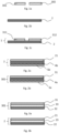
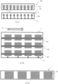
- Fig. 1a shows two donor foils 301, 302. It is possible here that at least one of the donor foils 301, 302 is a donor transfer foil, preferably a hot stamping, cold stamping, and/or a thermal transfer foil, and/or is a donor laminating foil. It is also possible for the dispenser films 301, 302 to be designed in the same way and/or different from one another.
- the donor films 301, 302 each comprise one or more assistant layers 11a, at least one decorative layer 4a, a delamination layer and/or at least one functional layer 5a.
- Fig. 1b shows a receiver film 2. It is possible that the receiver film is a receiver transfer film, preferably a hot stamping film or cold stamping film or thermal transfer film, or that the receiver film 2 is a receiver laminating film.
- the receiver film is a receiver transfer film, preferably a hot stamping film or cold stamping film or thermal transfer film, or that the receiver film 2 is a receiver laminating film.
- the receiver film 2 may comprise a receiver carrier layer 21, a decorative layer 4b, a delamination layer and/or a functional layer 5b.
- a decorative layer 4a, 4b each has one of the following or a combination of the following layers, in particular over the entire area and/or part of the area: one or more lacquer layers, one or more layers containing a liquid crystal material, one or more layers containing a thin film system, one or several metallic layers, one or more volume hologram layers, one or more layers having an optically active surface structure or an optically active surface relief, one or more reflection layers 10a, 10b.
- the receiver film 2 prefferably has one or more assistance layers 11b.
- An assistance layer 11a, 11b in particular has one of the following or a combination of the following layers: One or more adhesion promoter layers, one or more release layers, one or more protective layers and/or one or more pressure-receiving layers.
- Fig. 1c shows an example of a film intermediate product 1 comprising the in Fig. 1b receiver film 2 shown and two film elements 311, 312, each of which is formed by a section of the in Fig. 1a Donor films 301, 302 shown are formed and which are applied to the receiver film 2.
- Fig. 1a to Fig. 1c thus show a process for producing an intermediate film product 1.
- Fig. 1b shows step a), providing a receiver film 2.
- Fig. 1a shows step b), providing one or more donor films, with two donor films 301, 302 in particular being provided here.
- Fig. 1c shows the application of one or more film elements, which are each formed by a section of one of the one or more donor films, onto the receiver film 2 Fig. 1 a , whereby in particular the film elements 311, 312 are each formed by a section of the donor films 301, 302.
- the steps can be carried out in particular simply and/or multiple times in any order, preferably in the order mentioned above.
- a film element 311, 312 is formed by a section of a donor transfer film, in particular a section of a hot stamping film, a cold stamping film and/or a thermal transfer film. It is also possible for a film element 311, 312 to be formed from a section of a donor laminating film.
- the section of a donor film forming a respective film element 311, 312 may include the entire donor film 301, 302 or only a part and/or several parts of a donor film 301, 302.
- the intermediate film product 1 viewed perpendicular to a plane spanned by the intermediate film product, preferably in a top view based on the sectional view shown here, has at least two, preferably different, directly adjacent, at least partially overlapping and/or adjacent film elements, which during production on a film would be incompatible and/or at least would mean an increase in manufacturing time, a reduction in the quality of the features and/or higher rejects and/or higher manufacturing costs.
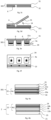
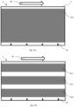
- Fig. 2a shows a receiver film 2, which comprises a receiver carrier layer 21, a decorative layer 4b and a functional layer 5b.
- the receiver carrier layer 21 preferably consists of PET, BOPP, PEN, PMMA, PC, ABS, PU, PVC and/or glass, and in particular has a layer thickness of 5 ⁇ m to 150 ⁇ m, preferably 10 ⁇ m to 75 ⁇ m.
- the decorative layer 4b is here, for example, arranged between the receiver carrier layer 21 and the functional layer 5b. It is also possible for the functional layer 5b to be arranged between the decorative layer 4b and the receiver carrier layer 21.
- the receiver film 2 prefferably has at least one delamination layer 18 and/or at least one assistant layer 11b.
- Fig. 2b shows a donor film 3, which includes a donor carrier layer 31, a decorative layer 4a and a functional layer 5a.
- the donor carrier layer 31 preferably consists of PET, BOPP, PEN, PMMA, PC, ABS, PU, PVC and / or glass, and in particular has a layer thickness of 5 ⁇ m to 150 ⁇ m, preferably 5 ⁇ m to 75 ⁇ m, more preferably 5 ⁇ m to 50 ⁇ m.
- the decorative layer 4a is here, for example, arranged between the donor carrier layer 31 and the functional layer 5a. It is also possible for the functional layer 5a to be arranged between the decorative layer 4a and the donor carrier layer 31.
- the donor film 301 may have at least one delamination layer 18 and/or at least one assistant layer 11b.
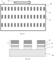
- Fig. 3a shows a donor film 301 comprising a donor carrier layer 31, a donor transfer layer 32 and a donor release layer 33.
- the donor release layer 33 is preferably arranged between the donor carrier layer 31 and further layers of the donor film 301.
- the donor transfer layer 32 preferably comprises one or more of the above-described assistant layers 11a, decorative layers 4a, functional layers 5a and/or delamination layers 18.
- the donor release layer 33 has the properties of a release layer.
- a release layer includes in particular one or more wax layers.
- a release layer preferably has an adhesive layer.
- the donor carrier layer 31 can be removed from the donor transfer layer 32 by the donor release layer 33.
- the donor carrier layer 31 can be separated from the donor transfer layer 32 in particular in a non-destructive manner. It is also possible for a film element 311, 312 transferred by means of the donor transfer layer 32 to be shaped during detachment.
- Fig. 3b shows a receiver film 2 comprising a receiver carrier layer 21, a receiver transfer layer 22 and/or a receiver release layer 23.
- the receiver release layer 23 is preferably arranged between the receiver carrier layer 21 and further layers of the receiver film 2.
- the receiver transfer layer 22 preferably comprises one or more of the above-described assistant layers 11a, decorative layers 4b, functional layers 5b and/or delamination layers 18.
- the receiver transfer layer 22 may have a transparent layer, in particular a layer that is transparent to the human eye at least in a partial area in the UV range with a wavelength of 400 nm to 240 nm and/or a color layer, which is preferred is printed.
- the receiver carrier layer 21 can be removed from the receiver transfer layer 22 by the receiver release layer 23.
- the receiver carrier layer 21 can therefore be separated from the receiver transfer layer 22 in a non-destructive manner.
- the receiver transfer layer 22 is particularly possible for the receiver transfer layer 22 to be shaped when the receiver transfer layer 22 is detached from the receiver carrier layer 21.
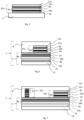
- Fig. 3c shows a donor film 301 with a donor transfer layer 32 and a donor carrier layer 31.
- the donor film 301 or the donor carrier layer 31 has a recess 6, which is introduced through the donor transfer layer 32 and partly into the donor carrier layer 31.
- the donor film 301 has a void and/or a complete and/or partial severance 7a of the donor carrier layer 31 and/or the donor transfer layer 32 and/or has additional severances 7a and/or recesses 6 of the donor carrier layer 31 and/or the donor transfer position 32.
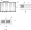
- Fig. 3d shows a dispenser film 301, which in Fig. 3c was described.
- the donor film 301 is a donor transfer film and the donor transfer layer 32 can be removed from the donor carrier layer 31.
- the donor film 301 or the donor carrier layer 31 has an optional recess 6, which is introduced into the donor transfer layer 32 and partly into the donor carrier layer 31.
- the donor film 301 is connected here, for example, to a receiver film 2.
- the donor carrier layer 31 is preferably detached from the donor transfer layer 32 at least partially, whereby in particular a first partial area of the donor transfer layer 32 remains as a film element 311 on the recipient film.
- the donor film 301 is a donor transfer film, which is in particular a hot stamping film
- the receiver film 2 is a receiver transfer film, which is in particular a hot stamping film.
- Further film elements are preferably formed from sections of the donor film 301, which is a donor transfer film, and/or from further one or more donor films 302, 303, 304.
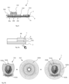
- Rollers are preferably used to adjust the take-off angle 14.
- pulling off the dispenser film 301 over an edge has proven to be useful.
- Particularly advantageous are very tapered edges, preferably with a small angle between the surfaces, since they allow, for example, a narrowly localized take-off location with a large take-off angle, preferably up to 180°.
- Mechanical separation aids are preferably used to break up the donor transfer layers 32 with sharp edges.
- a withdrawal angle 14 is set between 30° and 180°, preferably 90° and 180°.
- a lower detachment force for detaching the donor carrier layer 31 from the donor transfer layer 32 applied to the receiver film 2 is achieved than without recesses 6, severances 7a, 7b and/or empty spaces and/or at different take-off angles.
- relatively low thermal and/or mechanical loads are realized on the donor transfer layers 32 and/or the receiver film 2, which is preferably a receiver transfer film, preferably a hot stamping film.
- step c Through suitable process control, in particular with cold stamping and/or hot stamping, in step c), it has surprisingly been shown that even donor transfer layers 32 with relatively high release forces can be applied to a receiver film 2, which is preferably a receiver transfer film, whose receiver transfer layers are low Have detachment forces without the receiver transfer layer 22 being detached or detached from the receiver carrier layer 21 and/or a desired function in the film intermediate product 1 being lost, for example the function of a delamination layer.
- Fig. 3e shows an example of a donor film 301 with a donor carrier layer 31, a further donor carrier layer 31a and a donor transfer layer 32, with recesses 6 being made in the further donor carrier layer 31a, so that the donor film 301 is preferably like that in Fig. 3d dispenser film 301 described a receiver film 2 is applied and the donor carrier layer 31 and/or the further donor carrier layer 31a is advantageously detached.
- the donor transfer layer 32 further comprises a donor adhesive layer 34, which preferably serves to apply the respective donor transfer layer 32, which preferably forms a section of the donor foil 301 forming one or more foil elements 311 to 314, to the recipient foil 2.
- the donor transfer layer 32 preferably has a decorative layer 4a, which is formed, for example, by a printing layer.
- the further donor carrier layer 31a prefferably be designed to be detachable from the donor carrier layer 31, such that the further donor carrier layers 31a, preferably after the respective donor film 301 has been applied to a receiver film 2 and after the donor carrier layer 32 has subsequently been detached from one at least in some areas or several first partial areas of the respective donor transfer layer 32, remain as film elements on the receiver film 2.
- the donor film 301 with the further donor carrier layer 31a to form voids at the locations of the recesses 6, the further donor carrier layer 31a with the voids being applied to the donor carrier layer 31, preferably with a donor transfer layer 32 arranged on the further donor carrier layer 31a .
- the donor carrier layer 31 and/or the further donor carrier layers 31a are a PET carrier.
- Fig. 3f shows as an example the in Fig. 3e Dispenser foil shown in view from below.
- Register marks 13 are also applied here as an example.
- Fig. 4a shows an example of a donor film 301 with a donor carrier layer 31, a donor release layer 33 and a donor transfer layer 32, which has an optional donor adhesive layer 34, the donor adhesive layer 34 preferably being a heat-seal adhesive layer which is activated by means of pressure and heat.
- the pressure and heat in step c) are generated by hot stamping using a heated embossing stamp.
- the donor transfer layer 32 has a decorative layer 4a, preferably with a replication layer 9a, into which in particular at least one optically active surface structure is introduced, and which is preferably arranged between the optional donor adhesive layer 34 and the donor release layer 33.
- the decorative layer 4a has a reflection layer 10a between the replication layer 9a and the optional donor adhesive layer 24, preferably a metallic reflection layer, which is in particular partially applied, preferably at least partially applied to the at least one optically active surface structure of the replication layer 9a.
- the donor transfer layer prefferably has an assistant layer 11a between the donor release layer 33 and the replication layer 9a.
- assistant layer 11a between the donor release layer 33 and the replication layer 9a.
- Fig. 4b shows an example of a receiver film 2 with a receiver carrier layer 21, a receiver release layer 23 and a receiver transfer layer 22, which in particular has a receiver adhesive layer 24.
- the receiver transfer layer 22 in particular has a decorative layer 4b, preferably with a reflection layer 10b, which preferably has an HRI layer and/or has a partially transparent HRI layer, and which is arranged between the optional receiver adhesive layer 24 and the receiver release layer 23.
- the decorative layer 4b preferably has a replication layer 9b, into which in particular at least one further optically active surface structure is introduced and which is arranged between the reflection layer 10b and the receiver release layer 23.
- the receiver transfer layer 22 also preferably has an assistant layer 11b between the replication layer 9b and the receiver release layer 23.
- the receiver transfer layer 22 forms a diffractive feature, preferably a diffractive security feature.
- the reflection layer it is also possible for the reflection layer to have a thin film system.
- the receiver film 2 is a receiver transfer film, the receiver transfer layer 22 being removable from the receiver carrier layer 21, the detachment or separation of the receiver transfer layer 22 from the receiver carrier layer 21 being ensured preferably by a release layer 23, which comprises one or more wax layers.
- the reflection layer 10b is preferably at least partially applied to the at least one further optically active surface structure of the replication layer 9b.
- a receiver adhesive layer 24 is preferably arranged on the reflection layer 10b, preferably a heat seal adhesive layer, which is activated by means of pressure and heat.
- the pressure and heat in step c) are generated by hot stamping using a heated embossing stamp.
- the receiver adhesive layer 24 prefferably has an adhesion promoter layer, which preferably serves to improve the connection of the receiver adhesive layer 24 to the reflection layer.
- the receiver adhesive layer 24 is applied in particular partially, preferably applied individually to one or more first partial areas.
- the receiver adhesive layer 24 is radiation curable.
- step c) is preferably carried out by cold stamping, with the one or more donor films being connected to the recipient adhesive layer 24 and the adhesive being hardened by means of radiation.
- the donor transfer layers arranged in the one or more first partial areas on which the receiver adhesive layer 24 is arranged expediently remain adhered to the receiver film 2 as film elements 311 to 314.
- Fig. 5 shows as an example the in Fig. 4a Donor transfer layer 32 shown, which is applied to a receiver film 2 and thus forms a section of the donor film 301 forming a film element 311.
- an upper assistant layer 11a can be provided on the donor transfer layer 32 and/or the film element 311, which is arranged on the outermost side facing away from the receiver film 2.
- the upper assistant layer 11a has an adhesive layer, which is preferably an adhesive layer of the donor release layer 33 of the respective donor film 301, which forms the film element 311.
- the donor release layer 33 further has at least one wax layer, so that when the donor carrier layer 31 is detached from the donor transfer layer 32, this adhesive layer remains on the donor transfer layer 32 and as a layer of the film element 311 on the receiver film 2.
- This adhesive layer then serves in particular to connect the intermediate film product 1 to a target substrate.
- the shape of the applied film element 311 is determined in particular by the shape of the embossing die during hot stamping in step c).
- the shape of the applied film element 311 is determined by the fact that the adhesive layer is printed during cold stamping in step c), in particular that in step c) on the donor film 301 and / or on the receiver film 2 in one or An adhesive layer is printed on several first subregions 20b, in particular by means of a digital printing process, but is not printed on in one or more second subregions.
- the shape of the film element 311 is determined by recesses 6, severances 7a, 7b and/or voids, as shown in particular in Fig. 3d, Fig. 3e and Fig. 3f is described.
- the receiver film 2 prefferably be a receiver transfer film with a receiver transfer layer 21, with the film element 311 or further film elements being applied to the receiver transfer layer 21.
- Fig. 6 shows an example of a film intermediate product 1, with a film element 311 made from a section of a film as in Fig. 5 described donor transfer layer 32 to one as in Fig. 4b receiver film 2 described is applied.
- a further adhesive layer 8 is applied to the receiver film 2 and the donor transfer layer 32 or the film element 311, which has one or more layers and is preferably used to connect the film intermediate product 1 to a target substrate.
- the softening temperature of the donor adhesive layer 34 and the recipient adhesive layer 24 differs, and/or that the softening temperature of the donor adhesive layer 34 and/or the softening temperature of the recipient adhesive layer 24 differs from the softening temperature of the further adhesive layer 8, in particular that the Softening temperature of the donor adhesive layer 34 is at least 2.5 ° C below the softening temperature of the recipient adhesive layer 24, preferably at least 5 ° C below, preferably at least 7.5 ° C below.
- the softening temperature of the further adhesive layer 8 is at least 2.5 ° C below the softening temperature of the donor adhesive layer 34 and / or the recipient adhesive layer 24, in particular at least 5 ° C below, preferably at least 7.5 ° C falls below and/or that a softening of the further adhesive layer 8 is carried out, wherein the temperature of the donor adhesive layer 34 and / or the recipient adhesive layer 24 is at least 2.5 ° C lower, in particular at least 5 ° C lower, preferably at least 7.5 ° C lower than the softening temperature of the respective donor adhesive layer 34 or receiver adhesive layer 24.
- the donor adhesive layer 34 prefferably crosslinked chemically and/or by radiation, in particular after step c), and/or for the softening temperature of the donor adhesive layer 34 and/or recipient adhesive layer 24 to be increased after step c).
- Fig. 7 shows an example of a film intermediate product 1, which in addition to that in Fig. 6 shown film intermediate product 1, has a further film element 312.
- This film element 312 has, in particular in addition to that in Figure 5 described film element 311, a functional layer 5a.
- film elements which preferably have a decorative layer 4a, a functional layer 5a, an assistant layer 11a and/or a delamination layer 18, to be applied to the receiver film 2, preferably in any arrangement.
- a film element 314 it is also possible for a film element 314 to have a print layer with luminescent, preferably fluorescent, dyes.
- an intermediate film product 1, which has at least one functional layer 5a, 5b, is applied by injecting an injection molding compound onto the target substrate, with the injection molding compound in particular forming the target substrate.
- the intermediate film product 1 is preferably used as an insert sheet, in particular with a width of 10 mm to 800 mm, a length of 15 mm to 1200 mm and a thickness of 20 ⁇ m to 300 ⁇ m.
- Fig. 8 shows an example of a possible arrangement of film elements 311 to 314 on the receiver film.
- a section 7a and a recess 6 of a film element 313 are also shown as an example.
- a donor carrier layer 31 of a donor film 304 not shown here, to be detached in such a way that when the donor carrier layer 31 is detached at least in areas, first partial areas 20a remain as foil elements 314 on the receiver foil 2 and optionally second partial areas 20b of the donor transfer layer 32 with the Donor carrier layer 31 can be deducted.
- the film elements 314 are preferably similar and/or different from one another. It is also possible for the film elements 314 to be arranged, for example, in a regular one- or two-dimensional grid.
- severances 7a, 7b and/or recesses 6 are introduced, with the severances 7a, 7b and/or recesses 6 preferably being between the first and second portions 20a, 20b of the respective donor transfer layer 32 are introduced.
- Fig. 9a shows an example of a film intermediate product 1, which has a film element 311 applied to a receiver film 2.
- a further film element 312 is arranged on this film element 311.
- a further adhesive layer 8 is applied, which is preferably applied to the two film elements 311 and 312. Furthermore, it is particularly possible for the further adhesive layer 8 to also be in contact with the receiver film 2.
- the receiver film 2 is preferably non-removable, preferably non-removable and at least partially transparent, preferably at least partially transparent in the UV range and/or a range visible to the human eye.
- the receiver film 2 is at least partially removable, preferably that the receiver film 2 has a removable receiver carrier layer 21.
- a film element 311 is partially overlapped by another film element 312.
- the partially overlapped film element 311 completely and/or partially overlaps the other film element 312.
- optical effects of the further film element 312 are at least partially visible through the partially overlapped film element 311, preferably at least partially visible to the human eye.
- the partially overlapped film element 311 has a replication layer at least in an area overlapped by the further film element 312.
- the partially overlapped film element 311 preferably has a layer on its side facing away from the receiver film 2, which has one of the Receiver film 2 facing side of the further film element 312 is in contact, whereby a contact area KB is formed.
- the refractive index difference is preferably less than or equal to 0.2, preferably less than 0.1.
- the refractive index difference is less than 0.2, preferably less than 0.1. This is at least in 50% of the contact area KB.
- an HRI layer and/or a metal layer is provided in the remaining areas of the contact area KB.
- the refractive index difference is greater than 0.3, preferably greater than 0.5, with an HRI layer being provided in particular.
- Fig. 9b shows a concrete design example that includes the structure Fig. 9a can be realized.
- the film element 312 prefferably be applied to a receiver film 2 and for the film element 311 in the film intermediate product 1 to be applied to the receiver film 2, and in particular the film element 312, in such a way that it partially overlaps with the film element 312.
- the receiver film 2 is expediently preferably transparent and/or in particular not shown here.
- the film intermediate product 1 in particular starting from Fig. 9a shown in bottom view.
- a viewer thus looks, in particular when viewed vertically on a plane spanned by the film intermediate product 1, through the receiver film 2 and/or through the receiver carrier layer 21 and/or through the receiver transfer layer 22, onto the film elements 311, 312 of the film intermediate product 1.
- the decorative layer 4a of the film element 311 has several layers 311b provided over part of the surface.
- the layers 311b provided over part of the surface are each preferably arranged in a pattern, the patterns being in particular in the form of a coat of arms, a lion's head and a banner with the word "Kinegram”.
- a reflection layer in particular a metallic reflection layer, for example made of aluminum, is expediently arranged on the layers 311b provided over part of the area, the reflection layer preferably being arranged only in the layers 311b provided over part of the area.
- the layers 311b provided over part of the area preferably have optically variable effects.
- the layers provided over part of the surface expediently each comprise optically active surface structures, which in particular have microstructures.
- the film element 311 preferably has a coloring.
- the coloring is preferably formed by a translucent lacquer layer, which is expediently arranged between the receiver film 2 and the partially provided layers, so that the partially provided layers 311b for example, appear in gold colors, especially when looking at the foil element 311 in the product 100.
- the film element 311 and/or the receiver film 2 is transparent or semi-transparent at least over part of the surface.
- the decorative layer 4a of the film element 311 has a transparent or semi-transparent layer, which is in particular a lacquer layer, which is arranged at least outside the layers provided over part of the surface.
- the decorative layer 4a of the film element 311 may have a transparent or semi-transparent layer, which is in particular a lacquer layer, and/or a further transparent or semi-transparent layer, which is in particular a lacquer layer, which is arranged on the layers provided over part of the surface is.
- the receiver film 2 in particular the receiver transfer layer 22 and/or the receiver carrier layer 21, has a transparent or semi-transparent layer, which is in particular a lacquer layer or a plastic layer.
- areas of the film element 312 which do not overlap with the reflection layer of the film element 311 are recognizable to the viewer, in particular when viewed perpendicularly to a plane spanned by the film intermediate product 1, in particular in the film intermediate product 1 and / or in the product 100.
- the film element 312 preferably has optically variable effects.
- the film element 312 has a decorative layer 4a with a partial surface provided layer 312b, which preferably comprises a metal layer, for example made of aluminum, and serves in particular as a reflection layer.
- the layer 312b provided over part of the area is expediently arranged in a pattern; the layer 312b provided over part of the area preferably forms partially metallized lines.
- the partially metallized lines preferably form a guilloche.
- Optically active surface structures in particular microstructures, are expediently provided in the partial area layer 312b of the film element 312.
- the optically active surface structures in particular the microstructures, produce, for example, a sequential lighting of the lines, in particular as an apparent movement effect.
- the coloring of the film element 311, in particular the translucent lacquer layer of the film element 311, is not present in the partial surface layer 312b of the film element 312, in particular the partially metallized areas of the film element 312, the partial surface layer 312b of the film element 312 appears in a different color than the partially provided layers 311b of the film element 311.
- the guilloche of the film element 312 appears silver.
- Fig. 10a shows a possible step a), providing a receiver film 2, in a top view.
- the receiver film 2 is provided with the running direction 19 shown, preferably in a roll-to-roll process.
- the receiver film 2 already has decorative layers 4b.
- the receiver film 2 has register marks 13, which are in particular printed, diffractive and/or partially metallized, for register-accurate application of further layers and/or one or more film elements 311, 312, 313, 314. It is also possible for register marks to be arranged transversely to the running direction 19. It is also possible for layers of the receiver film 2 to take on the function of register marks, preferably diffractive elements of the receiver film 2. It is also possible for the receiver film 2 to have one or more decorative layers 4b, functional layers 5b and/or delamination layers.
- Fig. 10b shows a possible step c), an application of one or more film elements 311, 312, 313, 314, which is or are each formed by a section of one of the one or more donor films 301, 302, 303, onto the receiver film 2
- the film intermediate product 1 shown is produced, which has an example in Fig. 10a receiver film 2 described and various film elements 311, 312, 313, 314.
- the film elements 311, 312, 313, 314 are preferably applied in register.
- An intermediate film product 1 preferably has film elements 311, 312, 313, 314 that are similar and/or different from each other transversely to the running direction 19.
- the receiver foil 2 is a hot stamping foil and for step c) to be carried out by means of hot stamping, expediently at least one of the one or more donor foils 301 to 304 being a hot stamping foil.
- Fig. 10c shows a possible step b) of producing an intermediate film product 1, providing one or more donor films 301, 302, which are used, for example, for applying the in Fig. 10b shown film elements 311, 312, 313, 314 are provided.
- the donor films 301, 302 are provided in strips, for example. It is particularly possible for further donor films 303, 304 to be provided and/or for further film elements to be applied.
- step c) a step c1), bringing one or more donor films 301, 302 into contact with the receiver film 2, is carried out.
- step c2) it is further possible for a step c2) to be carried out, an at least partial detachment, in particular mechanical separation, of the donor carrier layer 32 from one or more first partial areas 20a of the respective donor transfer layer in such a way that the one or more first partial areas 20a remain on the receiver film 2 as film elements 311, 312, 313, 314.
- step c3) includes pulling off the respective donor carrier layer 31 with one or more second partial areas 20b of the respective donor transfer layer 32 from the one or more film elements 311 to 314.
- the dispenser film 302 shown above has cutout areas 311a, from which in particular the in Fig. 10b described film elements 312, 313, 314 are applied to the receiver film 2.
- the application to the receiver film 2 is carried out with a donor film 302 of the type shown above, preferably by means of a forming stamp, in particular with hot stamping.
- the pressure and heat required for hot embossing are generated in step c) by means of hot embossing using a heated embossing die.
- the dispenser film 301 shown below has cutout areas 311a, from which in particular the in Fig. 10b Film elements 311 described are applied to the receiver film 2.
- the donor film 301 preferably has at least partial cuts 7a, which enclose the cutout areas 311a.
- the cuts 7a are preferably made by punching.
- the application of the film elements 311 to 314 onto the receiver film 2 is carried out in the case of a donor film 302 of the type shown below, preferably by means of an embossing stamp, in which the shape of the stamp can be larger than that of a forming stamp, which is the same when applying a film element with the above Donor film 302 shown would be used to apply comparable film elements to the receiver film 2.
- the pressure and heat required for hot embossing are generated in step c) by means of hot embossing using a heated embossing die.
- a radiation-curable adhesive layer to be printed onto the receiver film 2 and/or one of the donor films 301, 302, in particular to be partially applied, preferably to be applied individually to one or more first partial areas.
- step c) is preferably carried out by means of cold stamping, whereby the one or more donor films 301, 302 are connected to the receiver film 2 and the adhesive is hardened by means of radiation.
- the respective donor carrier layer 31 is removed, the sections of the respective donor transfer layers 32 arranged in the one or more first subregions 20a on which the adhesive layer is arranged remain adhere to the receiver film 2 as film elements 311 to 314.
- Optional adhesion promoter layers on the receiver film 2 and/or at least one of the one or more donor films 301, 302 preferably secure the bond between the individual layers of the receiver film 2, the receiver transfer layer 22, at least one of the one or more donor films 301, 302 and/or the respective donor transfer layers 32.
- a web has similar and/or different cutout regions 311a to 314a and/or cutouts of the one or more donor films 301, 302 in the running direction 19 and/or transversely to the running direction 19.
- a donor film 301, 302 only covers an area of 0.2% to 20% in a top view or when viewed vertically on the respective donor film 301, 302 and the respective receiver film 2. , preferably an area of 0.5% to 5% of the receiver film 2.
- the donor films preferably have register marks 13, which enable the one or more film elements 311, 312, 313, 314 to be applied to the receiver film 2 in precise register.
- the two webs or the two dispenser films 301, 302 are preferably fed separately. In particular, the two dispenser films 301, 302 are manufactured separately.
- Fig. 10d shows a receiver film 2 with donor films 301, 302, 303 provided in strips.
- the application of the one or more film elements 311, 312, 313 is preferably carried out in register in the running direction 19 and/or transversely to the running direction 19.
- the web lines of the respective donor films 301 to 303 and/or the receiver film 2 are preferably adjusted for a register-accurate application of the film elements 311, 312, 313 to the receiver film 2.
- the feed distance of the receiver film 2 and/or the respective donor film 301, 302, 303 may be set for register-accurate application of the film elements 311, 312, 313 to the receiver film 2.
- the width of the strip of one of the one or more donor films 301, 302, 303 perpendicular to the running direction 19 varies over the length of the strip in the running direction 19, preferably that the outline shape of one of the one or several donor films 301, 302, 303 is at least partially non-linear, preferably wave-shaped.
- the shape design in particular the shape design of at least one film element 311, 312, 313, is carried out, for example, by partial pressure during cold stamping, an only partially applied hot stamping adhesive, and/or during hot stamping due to the shape of the stamping tool. It is also possible for the shape to be created by cutting the dispenser film 301, 302, 303.
- the extent of a film element 311, 312, 313, in particular a strip-shaped film element 311, 312, 313, is determined in strip form by the previous cutting of the respective dispenser film 301, 302, 303.
- the outline shape of one of the one or more film elements 311, 312, 313, which is preferably formed by a section of a strip-shaped dispenser film 301, 302, 303, runs in the form of lines, motifs and/or text.
- one or more of the one or more dispenser films 301 to 303 and / or one or more of the one or more film elements 311, 312, 313 has recesses and / or is interrupted, preferably by means of recesses 6, severances 7a and / or voids, like in particular Fig. 3c to Fig. 3f is described.
- the width of the strip of one of the one or more film elements 311, 312, 313, preferably perpendicular to the running direction 19, is in a width range of 0.5 mm to 10 mm, preferably of 1 mm to 5 mm.
- the width of the strip is one of the one or more film elements 311, 312, 313 for example, locally in the mentioned latitude range and preferably deviates locally from it.
- Fig. 10e shows by way of example a separation after step c), in particular by cutting and/or punching, of the receiver film 2 with the one or more film elements 311 to 314.
- the receiver film 2 with the film elements 311 to 314 preferably becomes a strip-shaped web and/or preferably several strip-shaped webs are cut, each of which preferably forms an intermediate film product 1.
- a single or multi-layer further adhesive layer 8 is preferably applied to the receiver film 2 and/or the one or more film elements 311 to 314.
- At least one layer of the further adhesive layer 8 is formed from the donor release layer 33.
- the further adhesive layer 8 is applied in such a way that differences in thickness of the intermediate film product 1 are at least partially compensated for.
- the width of the strip of the film intermediate product 1 varies over the length of the strip, preferably that the outline shape of the film intermediate product is at least partially non-linear, preferably wavy.
- the intermediate film product 1 prefferably to be applied to a target substrate in order to produce a product, preferably in a laminator, a hot stamping device, a cold stamping device and/or applied to a target substrate in an application system.
- the film intermediate product 1 prefferably be applied by injecting an injection molding compound onto the target substrate, in particular where the injection molding compound forms the target substrate. It is particularly possible here for the intermediate film product 1 to be deformed beforehand, in particular to be deep-drawn.
- the intermediate film product 1 is preferably applied as an insert sheet to an injection molding compound and has a width in the range of 10 mm to 800 mm and a length in the range of 15 mm to 1200 mm.
- the thickness of the intermediate film product 1 is preferably 20 ⁇ m to 300 ⁇ m, the thickness varying in particular over the width and length of the intermediate film product 1.
- the intermediate film product 1 is preferably applied to a porous target substrate, such as paper, which absorbs the adhesive differently depending on the local pressure, so that more adhesive penetrates into the target substrate in areas of the intermediate film product 1 with greater thicknesses. This in particular prevents any disruptive steps from being visible on the surface of the product due to the different thicknesses.
- a porous target substrate such as paper
- the surface can be leveled by allowing the adhesive to flow when applied to the target substrate.
- the intermediate film product 1 is used to produce a surface of the product and is applied to a target substrate, for example a paper, a cardboard, a plastic film, a substrate made of one or more plastic and/or paper layers, a substrate comprising one or more decorative layers and/or or a carrier layer is applied.
- a target substrate for example a paper, a cardboard, a plastic film, a substrate made of one or more plastic and/or paper layers, a substrate comprising one or more decorative layers and/or or a carrier layer is applied.
- the total thickness of the single or multi-layer further adhesive layer 8 is preferably more than the maximum difference in thickness between the areas with the one or more film elements 311 to 314 and those areas without film elements 311 to 314, thus the contours of the film elements 311 to 314 on the surface are not clearly visible.
- the total thickness of the single or multi-layer further adhesive layer 8 is preferably more than the difference between the largest thickness of the intermediate film product 1 and the smallest thickness of the intermediate film product 1, so that the contours of the film elements 311 to 314 are not clearly visible on the surface.
- the thickness of the further adhesive layer 8 is applied, in particular partially, such that it is thicker in the areas of the receiver film 2 without film elements 311 to 314 and/or in regions with the lowest thickness of the intermediate film product than in the regions of the receiver film 2 with film elements 311 to 314 and/or in areas with the greatest thickness of the film intermediate product 1.
- An additional auxiliary layer which expediently forms a layer of the single or multi-layer adhesive layer 8, is preferably applied partially in register, which compensates for differences in thickness of the intermediate film product 1.
- the single or multi-layer further adhesive layer 8 is then preferably applied in a homogeneous layer thickness.
- at least one layer of the further adhesive layer 8 is applied in a homogeneous layer thickness.
- the adhesive is thermally relatively stable after curing and/or only comparatively little heat and pressure is introduced during transfer to the target substrate.
- Fig. 11a shows an example of a receiver film 2 with a surface-transferred film element 311.
- the donor film 301 is a donor transfer film.
- the receiver film 2 also has a delamination layer 18.
- a delamination layer that allows local partial delamination to serve as protection against manipulation is particularly advantageous. It is also possible for the donor film 301 to have a delamination layer 18.
- the thickness of the donor transfer layer 32 is in a range from 1 ⁇ m to 15 ⁇ m, preferably in a range from 2 ⁇ m to 10 ⁇ m.
- the thickness of the receiver carrier layer is preferably in a range from 5 ⁇ m to 150 ⁇ m, preferably in a range from 10 ⁇ m to 50 ⁇ m.
- the advantage here is that features on transfer films are manufactured independently of the properties and/or process capability, preferably the manufacturing requirements, of the delamination layer.
- This preferably produces a combination of optical effects, which are provided in particular with the one or more donor films 301 to 304, with the function of a delamination layer, which is provided in particular by the delamination layer 18 of the receiver film 2.
- a combination is not possible when produced on a film and/or can only be produced with higher costs, more rejects, poorer protection against counterfeiting and/or poorer quality.
- a film element 311 to 314 has optical effects that have a very high replication quality, which requires high temperatures and high pressure. However, due to the high pressure and high temperatures, the delamination layer would be damaged if manufactured on the same film.
- Fig. 11b shows an example of a receiver film 2 with film elements 311, 312, 313 transferred in strips.
- the donor film 301 is a donor transfer film.
- the receiver film 2 also has a delamination layer 18. It is also possible for the donor film 301 to have a delamination layer 18.
- Fig. 11c shows a film intermediate product 1 in a top view, which has several labels 15.
- the labels 15 each include at least one section of the receiver film 2 and at least one film element 311 to 314.
- Fig. 11d shows that in Fig. 11c Illustrated film intermediate product 1 in a schematic sectional view.
- the receiver film 2 is preferably applied to a carrier 40, in particular a siliconized carrier.
- PSA Pressure Sensitive Adhesive
- the receiver film 2 with the applied film elements 311 to 314 by means of the further Adhesive layer 8 is laminated onto the carrier 40, and that optionally the receiver film 2 is punched and weeded.
- the receiver film 2 is punched and weeded before being connected to the carrier 40 and/or punched and weeded after being connected to the carrier 40.
- the labels 15 can be removed from the carrier 40 in a non-destructive manner using the PSA adhesive layer.
- the further adhesive layer 8 which is in particular a PSA adhesive layer, to be applied to the carrier 40, the receiver film 2 and/or partial areas of the receiver film 2.
- one or more labels 15 are detached from the carrier 40 and applied to a further object, the delamination layer 18 being intended to cause the label 15 to delaminate and/or tear when the label 15 is attempted to be detached from the further object Layers of the label 15 effects.
- Fig. 12a shows an example of the provision of a receiver film 2, which is in particular a receiver laminating film with a receiver carrier layer 21, and an enlarged view of a feature area MB of a decorative layer 4b, which is preferably arranged on the receiver carrier layer 21 of the receiver film 2.
- the decorative layer 4b preferably has at least one feature area MB, in particular a plurality of feature areas MB.
- the decorative layer 4b preferably forms one or more security features using the feature areas MB.
- a feature area MB preferably has at least one first decorative element 17b.
- several feature areas MB and/or several first decorative elements 17b are provided in a regular one- or two-dimensional grid.
- the decorative layer 4b in the feature areas MB further has an at least partially transparent layer, at least one at least partially designed transparent reflection layer and/or at least one at least partially designed metallic reflection layer and/or an at least partially designed print.
- the receiver film 2 prefferably has an assistant layer 11b, in particular an adhesion promoter layer.
- register marks it is also possible for register marks to be provided on the receiver film 2.
- an intermediate film product 1 is thus produced, which is used to produce a security document, in particular a banknote.
- Fig. 12b shows an example of one in Fig. 12a enlarged feature area MB of the receiver film 2, wherein a second decorative element 17a is applied, which is formed by a film element 311, the film element 311 being formed by a section of one of the one or more donor films 301 to 304, which is in particular a donor transfer film.
- the second decorative element 17a differs from the first decorative element 17b.
- the film element 311 preferably has a printing layer, in particular a lacquer layer, and/or a diffraction-optical element, which consists of a replication layer with a molded diffractive surface structure, which is covered at least in partial areas by a reflection layer.
- first and second decorative elements 17a, 17b can at least partially overlap one another and/or one another and/or for further decorative elements to be applied which overlap one another and/or to overlap the first and/or second decorative elements 17a, 17b .
- the intermediate film product 1 preferably points, preferably when viewed perpendicularly, on a plane spanned by the intermediate film product, preferably as in the Fig. 12b shown top view, at least two different directly adjacent, at least partially overlapping and / or adjacent decorative elements. These are preferably each formed by at least one film element 311, 312 and/or by the receiver film 2.
- the receiver film 2 and the one or more donor films 301, 302 are preferably supplied separately.
- the donor films 301, 302 and the receiver film 2 are manufactured separately.
- the decorative elements 17a, 17b preferably each consist of areas of the decorative layer 4a, 4b of the receiver film 2 and/or the one or more donor films 301 to 304, which differ from the surrounding areas in a contrasting manner.
- a lacquer layer of the decorative layer in the area of the decorative elements is colored differently than the surrounding areas and/or is only provided in the area of the decorative elements.
- a surface structure, for example a diffractive surface relief, of the decorative layer 4a, 4b can only be provided in the area of the decorative elements 17a, 17b or can have a different surface relief than the surrounding areas.
- a metallic reflection layer of the decorative layer 4a, 4b can only be provided in the area of the decorative elements 17a, 17b but not in the surrounding areas.
- the decorative layer 4a, 4b is preferably designed to be transparent in the area outside the decorative elements 17a, 17b.
- a functional layer 5a, 5b of the one or more donor films 301 to 304 and/or the receiver film 2 can be designed so that the function, for example an electrical function, is only formed in the area of the decorative elements 17a, 17b.
- an electrical component for example a display and/or an antenna
- an electrical component for example a display and/or an antenna
- the decorative elements prefferably be provided by the applied cutouts of the one or more donor foils 301 to 304 and for their shape to be defined by the cutout and not by a corresponding design of the decorative layer 4a of the donor foil 301 to 304.
- an intermediate film product 1 is thus produced, which is used to produce a security document, in particular a banknote, an ID document, a credit card and/or a bank card.
- an intermediate film product 1 which in particular has a thread-like security feature, the width of which is preferably in a range of 0.5 mm to 15 mm, preferably in a range of 1.5 mm to 7.5 mm .
- an additional film is applied to the receiver film 2 with the film elements 311 to 314.
- the additional film consists in particular of PET and preferably has a thickness in the range from 5 ⁇ m to 50 ⁇ m, preferably in the range from 5 ⁇ m to 20 ⁇ m. This has the particular advantage that the film elements 311 to 314 are enclosed and protected.
- an adhesive coating to be applied on one or both sides to ensure anchoring in the target substrate, for example as a thread in paper or embedded in plastic.
- the intermediate film product 1 is then cut into strips.
- the second decorative elements 17a only cover an area in the range of 10% to 90%, preferably an area in the range of 20% to 80%, of the receiver film 2 in a top view or when viewed perpendicularly to the receiver film 2 after the respective film elements have been applied .
- the decorative elements 17a of the one or more donor films 301 to 304 can be transferred to a laminating film as a receiver film 2 in such a way that the laminating film is not covered in some areas by the decorative elements 17a of the donor films 301 to 304.
- a layer of adhesive is then applied over the entire area.
- the adhesive layer connects the laminating film and the target substrate in these partial areas directly without any donor transfer layers 32 in between, so that a high level of adhesion is achieved. It is particularly advantageous if the features of the dispenser film, in particular the film elements 311 to 314, preferably the decorative elements 17a, are transferred as a filigree pattern.
- the area occupancy is advantageously between 10% and 90%, and further between 20% and 80%.
- Fig. 13a shows an example of a film intermediate product 1 applied to an injection molding compound SGM, the film intermediate product 1 being back-injected in particular with the injection molding compound SGM.
- the film intermediate product 1 has a receiver film 2 as a receiver transfer film, with at least one film element 311 to 314 being applied to the receiver transfer film 22.
- the receiver film 2 has a receiver carrier layer 21, which preferably protects the receiver transfer layer 2 from damage.
- the receiver carrier layer 21 is preferably firmly connected to the receiver transfer layer 2 and/or designed to be removable.
- the intermediate film product 1 preferably has at least one functional layer 5a, 5b, for example a display, and/or at least one decorative layer 4a, 4b, for example a lacquer layer.
- Fig. 13b shows that in Fig. 13a Product 100 shown, with the receiver carrier layer 21 being detached.
- the intermediate film product 1 it is also possible for the intermediate film product 1 to have been previously laminated, cold-stamped and/or hot-embossed onto a product and/or target substrate.
- the receiver transfer layer 22 prefferably has a surface structure, in particular a surface relief, after the receiver carrier layer 21 has been detached.
- a printed varnish is preferably arranged between the receiver carrier layer 21 and the receiver transfer layer 22, in particular on the receiver carrier layer 21.
- a replication layer is arranged between the receiver carrier layer 21 and the receiver transfer layer 22, in particular on the receiver carrier layer 21, which is preferably radiation-curable.
- a surface structure is preferably introduced into this replication layer, which creates a decorative effect after the receiver carrier layer 21 and the replication layer have been removed.
Claims (18)
- Procédé de fabrication d'un produit intermédiaire de feuille (1),comprenant les étapes suivantes, lesquelles sont mises en œuvre en particulier une fois et/ou plusieurs fois dans un ordre quelconque, de manière préférée dans l'ordre suivant :a) la fourniture d'une feuille réceptrice (2)b) la fourniture d'une ou de plusieurs feuilles donneuses (301 à 304)c) l'application sur la feuille réceptrice (2) d'un ou de plusieurs éléments de feuille (311 à 314), lequel est formé ou lesquels sont formés respectivement par une découpe d'une des une ou plusieurs feuilles donneuses (301 à 304) ;dans lequel la feuille réceptrice (2) est une feuille réceptrice de transfert, dans lequel la feuille réceptrice de transfert présente une couche réceptrice de support (21) et une couche réceptrice de transfert (22), dans lequel la couche réceptrice de transfert (22) peut être décollée de la couche réceptrice de support (21) et/ou présente une couche réceptrice de décollement (23), laquelle est disposée entre la couche réceptrice de transfert (22) et la couche réceptrice de support (21),et au moins une des une ou plusieurs feuilles donneuses (301 à 304) est une feuille donneuse de transfert, qui présente une couche donneuse de support (31) et une couche donneuse de transfert (32), dans lequel la couche donneuse de transfert (32) peut être décollée de la couche donneuse de support (31) et/ou présente une couche donneuse de décollement (33), laquelle est disposée entre la couche donneuse de transfert (32) et la couche donneuse de support (31),caractérisé en ceque la force de décollement entre la couche donneuse de support (31) et la couche donneuse de transfert (32) est inférieure à la force de décollement entre la couche réceptrice de support et la couche réceptrice de transfert (22).
- Procédé selon la revendication 1,
caractérisé en ceque la feuille réceptrice (2) est une feuille d'estampage à chaud, une feuille d'estampage à froid ou une feuille de transfert thermique,et/ou la feuille donneuse de transfert est choisie parmi : une feuille d'estampage à chaud, une feuille d'estampage à froid et une feuille de transfert thermique,et/ou que l'étape c) est mise en œuvre au moyen d'un estampage à chaud et/ou d'un estampage à froid et/ou d'un transfert thermique. - Procédé selon l'une quelconque des revendications précédentes,
caractérisé en ce
que dans l'étape c), des étapes suivantes sont mises en oeuvre :c1) la mise en contact d'une ou de plusieurs feuilles donneuses de transfert avec la feuille réceptrice (2),c2) le décollement au moins par endroits, en particulier la séparation mécanique, de la couche donneuse de support (31) d'une ou de plusieurs premières zones partielles (20a) de la couche donneuse de transfert (32) respective de telle manière que les une ou plusieurs premières zones partielles (20a) restent sur la feuille réceptrice (2) en tant qu'un ou plusieurs des un ou plusieurs éléments de feuille (311 à 314),c3) en option le retrait de la couche donneuse de support (31) respective avec une ou plusieurs deuxièmes zones partielles (20b) de la couche donneuse de transfert (32) respective des un ou plusieurs éléments de feuille (311 à 314). - Procédé selon l'une quelconque des revendications précédentes,
caractérisé en cequ'une ou plusieurs des premières zones partielles (20a) sont fixées individuellement dans l'étape c), en particulier au moyen d'un procédé d'impression numérique, de préférence au moyen d'une impression à jet d'encre, au moyen d'une tête d'impression par transfert thermique et/ou au moyen d'un rayonnement, en particulier au moyen d'un pilotage d'une matrice d'exposition,et/ou un ou plusieurs thermoéléments, en particulier d'une tête d'impression par transfert thermique, sont pilotés dans l'étape c),et/ou une couche adhésive est appliquée par impression, en particulier au moyen d'un procédé d'impression numérique, sur une ou plusieurs des feuilles donneuses (301 à 304) et/ou sur la feuille réceptrice (2) dans une ou plusieurs des premières zones partielles (20a) dans l'étape c), n'est toutefois pas appliquée par impression dans les une ou plusieurs deuxièmes zones partielles (20b),et/ou une couche adhésive, en particulier une couche adhésive de la feuille réceptrice (2) et/ou une couche adhésive d'une ou de plusieurs des feuilles donneuses (301 à 304) sont activées dans les une ou plusieurs premières zones partielles (20a) dans l'étape c), en particulier sont activées thermiquement et/ou par rayonnement, ne sont toutefois pas activées dans les une ou plusieurs deuxièmes zones partielles (20b) . - Procédé selon l'une quelconque des revendications précédentes,
caractérisé en ce
que la feuille réceptrice (2) est une feuille d'estampage à chaud, et qu'au moins une des une ou plusieurs feuilles donneuses (301 à 304) est une feuille d'estampage à chaud. - Procédé selon l'une quelconque des revendications précédentes,
caractérisé en ceque de préférence au moins lors de la mise en œuvre de l'étape c), la force de décollement entre la couche donneuse de support (31) et la couche donneuse de transfert (32) est inférieure d'au moins 10 %, de préférence d'au moins 20 % à la force de décollement entre la couche réceptrice de support et la couche réceptrice de transfert (22)et/ou que la force de décollement de la couche donneuse de support (31) de la couche donneuse de transfert (32) se situe dans la plage de 0,3 cN par cm de largeur de bande à 50 cN par cm de largeur de bande, de manière préférée de 0,3 cN par cm de largeur de bande à 15 cN par cm de largeur de bande, mesurée en particulier selon le procédé FINAT FTM2, et/ou que la force de décollement de la couche réceptrice de support (21) de la couche réceptrice de transfert (22) se situe dans la plage de 0,3 cN par cm de largeur de bande à 75 cN par cm de largeur de bande, de manière préférée de 1,5 cN par cm de largeur de bande à 50 cN par cm de largeur de bande, en particulier mesurée selon le procédé FINAT FTM2. - Procédé selon l'une quelconque des revendications précédentes,
caractérisé en cequ'au moins une des une ou plusieurs feuilles donneuses (301 à 304) est une feuille donneuse de laminage,et/ou qu'au moins une des une ou plusieurs feuilles donneuse (301 à 304) et/ou une ou plusieurs découpes des au moins une ou plusieurs feuilles donneuses (301 à 304), lesquelles forment un ou plusieurs des un ou plusieurs éléments de feuille (311 à 314), sont appliquées sur la feuille réceptrice (2) dans l'étape c) au moyen d'un laminage. - Procédé selon l'une quelconque des revendications précédentes,
caractérisé en ceque la feuille réceptrice (2) présente une couche adhésive réceptrice (24) sur le côté tourné vers la feuille des une ou plusieurs feuilles donneuses (301 à 304) dans l'étape c) et/ou les une ou plusieurs feuilles donneuses (301 à 304) présentent sur le côté tourné vers la feuille réceptrice (2) dans l'étape c) respectivement une couche adhésive donneuse (34),et qu'une autre couche adhésive (8) est appliquée sur un substrat cible, sur la feuille réceptrice (2) et/ou sur les une ou plusieurs feuilles donneuses (301 à 304) et/ou la couche donneuse de transfert (32) respective, en particulier dans lequel l'autre couche adhésive (8) est utilisée après l'étape c) pour relier le produit intermédiaire de feuille (1) à un substrat cible, dans lequel l'autre couche adhésive (8) est monocouche ou multicouche,en particulier dans lequel l'autre couche adhésive (8) est appliquée en tant que couche adhésive d'une couche d'aide (11a) et/ou d'une couche donneuse de décollement (23) des une ou plusieurs feuilles donneuses (301 à 304) . - Procédé selon la revendication 8,
caractérisé en ceque la température de ramollissement de la couche adhésive donneuse (34) et celle de la couche adhésive réceptrice (24) sont différentes, et/ou que la température de ramollissement de la couche adhésive donneuse (34) et/ou la température de ramollissement de la couche adhésive réceptrice (24) sont différentes de la température de ramollissement de l'autre couche adhésive (8), de préférence dans lequel la température de ramollissement de la couche adhésive donneuse (34) ne dépasse pas la température de ramollissement de la couche adhésive réceptrice (24) d'au moins 2,5°C, en particulier ne la dépasse pas d'au moins 5 C, ne la dépasse pas de manière préférée d'au moins 7,5 C et/ou la température de ramollissement de l'autre couche adhésive (8) ne dépasse pas la température de ramollissement de la couche adhésive donneuse (34) et/ou de la couche adhésive réceptrice (24) d'au moins 2,5 C, en particulier ne la dépasse pas d'au moins 5 C, ne la dépasse pas de manière préférée d'au moins 7,5 C,et/ou qu'un ramollissement de l'autre couche adhésive (8) est mis en oeuvre, dans lequel la température de la couche adhésive donneuse (34) et/ou de la couche adhésive réceptrice (24) sont inférieures d'au moins 2,5 C, en particulier sont inférieurs d'au moins 5 C, sont inférieures de manière préférée d'au moins 7,5 C à la température de ramollissement de la couche adhésive donneuse (34) ou de la couche adhésive réceptrice (24) respective. - Procédé selon l'une quelconque des revendications précédentes,
caractérisé en ce
que la couche adhésive donneuse (34) est réticulée en particulier après l'étape c) par voie chimique et/ou par rayonnement, et/ou que la température de ramollissement de la couche adhésive donneuse (34) et/ou de la couche adhésive réceptrice (24) est augmentée après l'étape c). - Procédé selon l'une quelconque des revendications précédentes,
caractérisé en ceque dans l'étape c), un ou plusieurs des éléments de feuille (311 à 314) sont appliqués de telle manière qu'ils chevauchent seulement par endroits la feuille réceptrice (2),en particulier que dans l'étape c), les un ou plusieurs éléments de feuille (311 à 314) sont appliqués de telle manière qu'ils chevauchent respectivement moins de 5 % de la surface de la feuille réceptrice (2). - Procédé selon l'une quelconque des revendications précédentes,
caractérisé en cequ'une ou plusieurs séparations (7a, 7b), un ou plusieurs emplacements vides et/ou évidements (6) sont pratiqués au moins dans une des une ou plusieurs feuilles donneuses (301 à 304), en particulier dans la couche donneuse de transfert (32), dans lequel de préférence les une ou plusieurs séparations (7a, 7b), les un ou plusieurs emplacements vides et/ou évidements (6) sont pratiqués entre les premières et deuxièmes zones partielles (20a, 20b) de la couche donneuse de transfert (32) respective,et/ou que la feuille réceptrice (2) et/ou au moins une des une ou plusieurs feuilles donneuses (301 à 304) est fournie avec une ou plusieurs séparations (7a, 7b), un ou plusieurs emplacements vides et/ou évidements (6), en particulier dans lequel la forme des une ou plusieurs séparations (7a, 7b), des un ou plusieurs emplacements vides et/ou évidements (6) est choisie parmi : forme de bande, ronde, circulaire, ovale, polygonale, rectangulaire, carrée, sous la forme de caractères alphanumériques, de logos, de microtextes, d'images, de portraits et/ou de pictogrammes, dans lequel la forme des un ou plusieurs emplacements vides, évidements (6) et/ou des une ou plusieurs séparations (7a, 7b) est de préférence identique ou différente, et/ou dans lequel les une ou plusieurs séparations (7a, 7b), les uns ou plusieurs emplacements et/ou évidements (6) sont réalisés au moyen d'un découpage, d'un poinçonnage, d'un poinçonnage par levage, d'un poinçonnage semi-rotatif et/ou d'un poinçonnage rotatif, d'un aiguilletage et/ou d'un laser. - Procédé selon l'une quelconque des revendications précédentes,
caractérisé en ce
qu'après l'étape c), une isolation est mise en œuvre en particulier par découpage et/ou poinçonnage de la feuille réceptrice (2) avec les un ou plusieurs éléments de feuille (311 à 314). - Produit intermédiaire de feuille (1) fabriqué selon un procédé selon l'une quelconque des revendications précédentes,
comprenant une feuille réceptrice (2) et un ou plusieurs éléments de feuille (311 à 314), lequel est formé ou lesquels sont formés respectivement par une découpe d'une ou de plusieurs feuilles donneuses (301 à 304) et lequel est appliqué ou lesquels sont appliqués sur la feuille réceptrice (2). - Produit intermédiaire de feuille (1) selon la revendication 14,
caractérisé en ce
que la feuille réceptrice (2) et/ou les un ou plusieurs éléments de feuille (311 à 314) présentent au moins une couche décorative (4a, 4b) et/ou au moins une couche fonctionnelle (5a, 5b), en particulier une couche, qui réalise une fonction électrique et/ou une fonction microfluidique et/ou une fonction optique, de préférence un capteur, un capteur tactile, un écran, une DEL, une OLED, une antenne, un élément RFID, une cellule solaire et/ou un circuit électrique et/ou présentent une couche de délaminage. - Produit intermédiaire de feuille (1) selon la revendication 14 ou 15,
caractérisé en ceque la feuille réceptrice (2) est une feuille d'estampage à chaud, une feuille d'estampage à froid ou une feuille de transfert thermique,et/ou qu'au moins un des éléments de feuille (311 à 314) est une découpe d'une feuille d'estampage à chaud, d'une feuille d'estampage à froid et/ou d'une feuille de transfert thermique. - Produit intermédiaire de feuille (1) selon l'une quelconque des revendications 14 à 16,
caractérisé en ce
qu'au moins un des un ou plusieurs éléments de feuille (311 à 314) est une découpe d'une feuille donneuse de laminage. - Procédé de fabrication d'un produit (100),
où un produit intermédiaire de feuille (1) selon l'une quelconque des revendications 14 à 17 est employé ou où un produit intermédiaire de feuille (1) fabriqué selon un procédé selon l'une quelconque des revendications 1 à 13 est employé et/ou où un procédé selon l'une quelconque des revendications 1 à 13 est mis en œuvre.
Priority Applications (1)
| Application Number | Priority Date | Filing Date | Title |
|---|---|---|---|
| EP24150765.6A EP4331859A2 (fr) | 2018-12-14 | 2019-12-09 | Procédé de fabrication d'un produit intermédiaire de feuille, produit intermédiaire de feuille et procédé de fabrication d'un produit |
Applications Claiming Priority (2)
| Application Number | Priority Date | Filing Date | Title |
|---|---|---|---|
| DE102018132321.2A DE102018132321A1 (de) | 2018-12-14 | 2018-12-14 | Verfahren zur Herstellung eines Folienzwischenprodukts, Folienzwischenprodukt sowie Verfahren zur Herstellung eines Produkts |
| PCT/EP2019/084246 WO2020120403A1 (fr) | 2018-12-14 | 2019-12-09 | Procédé de fabrication d'un produit intermédiaire de feuille, produit intermédiaire de feuille ainsi que procédé de fabrication d'un produit |
Related Child Applications (1)
| Application Number | Title | Priority Date | Filing Date |
|---|---|---|---|
| EP24150765.6A Division EP4331859A2 (fr) | 2018-12-14 | 2019-12-09 | Procédé de fabrication d'un produit intermédiaire de feuille, produit intermédiaire de feuille et procédé de fabrication d'un produit |
Publications (2)
| Publication Number | Publication Date |
|---|---|
| EP3894232A1 EP3894232A1 (fr) | 2021-10-20 |
| EP3894232B1 true EP3894232B1 (fr) | 2024-01-24 |
Family
ID=68841128
Family Applications (2)
| Application Number | Title | Priority Date | Filing Date |
|---|---|---|---|
| EP24150765.6A Pending EP4331859A2 (fr) | 2018-12-14 | 2019-12-09 | Procédé de fabrication d'un produit intermédiaire de feuille, produit intermédiaire de feuille et procédé de fabrication d'un produit |
| EP19817685.1A Active EP3894232B1 (fr) | 2018-12-14 | 2019-12-09 | Procédé de fabrication d'un produit intermédiaire de feuille, produit intermédiaire de feuille ainsi que procédé de fabrication d'un produit |
Family Applications Before (1)
| Application Number | Title | Priority Date | Filing Date |
|---|---|---|---|
| EP24150765.6A Pending EP4331859A2 (fr) | 2018-12-14 | 2019-12-09 | Procédé de fabrication d'un produit intermédiaire de feuille, produit intermédiaire de feuille et procédé de fabrication d'un produit |
Country Status (8)
| Country | Link |
|---|---|
| US (1) | US20220055363A1 (fr) |
| EP (2) | EP4331859A2 (fr) |
| JP (1) | JP7441222B2 (fr) |
| CN (1) | CN113195240B (fr) |
| CA (1) | CA3119824A1 (fr) |
| DE (1) | DE102018132321A1 (fr) |
| FI (1) | FI3894232T3 (fr) |
| WO (1) | WO2020120403A1 (fr) |
Families Citing this family (2)
| Publication number | Priority date | Publication date | Assignee | Title |
|---|---|---|---|---|
| DE102019134562B4 (de) * | 2019-12-16 | 2022-09-22 | Fresenius Medical Care Deutschland Gmbh | Medizinisches Produkt mit Kennzeichnung und Verfahren zum Aufbringen einer Kennzeichnung auf ein medizinisches Produkt |
| DE102020121896A1 (de) | 2020-08-20 | 2022-02-24 | Leonhard Kurz Stiftung & Co. Kg | Mehrschichtkörper und ein Verfahren zur Herstellung eines Mehrschichtköpers |
Citations (2)
| Publication number | Priority date | Publication date | Assignee | Title |
|---|---|---|---|---|
| WO2005108108A2 (fr) * | 2004-04-30 | 2005-11-17 | Giesecke & Devrient Gmbh | Element de securite et son procede de production |
| WO2016092044A1 (fr) * | 2014-12-10 | 2016-06-16 | Leonhard Kurz Stiftung & Co. Kg | Support d'absorption, film de transfert, élément de sécurité et procédé d'individualisation d'un élément de sécurité |
Family Cites Families (8)
| Publication number | Priority date | Publication date | Assignee | Title |
|---|---|---|---|---|
| US20090250158A1 (en) | 2005-10-27 | 2009-10-08 | Christina Streb | Method for Transferring a Multilayer Body and a Transfer Film |
| DE102008062149B3 (de) | 2008-12-16 | 2010-04-29 | Ovd Kinegram Ag | Verfahren zur Herstellung eines Sicherheitselements sowie Transferfolie |
| DE102010019766A1 (de) * | 2010-05-07 | 2011-11-10 | Giesecke & Devrient Gmbh | Verfahren zur Erzeugung einer Mikrostruktur auf einem Träger |
| DE102010020039A1 (de) | 2010-05-11 | 2011-11-17 | Volkswagen Ag | Verfahren zur Herstellung eines Verkleidungsteils aus Kunststoff sowie Verkleidungsteil aus Kunststoff |
| US20130118681A1 (en) * | 2011-11-16 | 2013-05-16 | Lee-Chung Lin | Fabricating method for electronic card |
| DE102014112073A1 (de) * | 2014-08-22 | 2016-02-25 | Ovd Kinegram Ag | Transferfolie sowie Verfahren zur Herstellung einer Transferfolie |
| DE102015112909B3 (de) * | 2015-08-05 | 2017-02-09 | Leonhard Kurz Stiftung & Co. Kg | Verfahren und Vorrichtung zum Herstellen einer Mehrschichtfolie |
| DE102015121849A1 (de) * | 2015-12-15 | 2017-06-22 | Ovd Kinegram Ag | Verfahren zur Herstellung eines Sicherheitselements sowie Transferfolie |
-
2018
- 2018-12-14 DE DE102018132321.2A patent/DE102018132321A1/de active Pending
-
2019
- 2019-12-09 CN CN201980082782.9A patent/CN113195240B/zh active Active
- 2019-12-09 FI FIEP19817685.1T patent/FI3894232T3/fi active
- 2019-12-09 WO PCT/EP2019/084246 patent/WO2020120403A1/fr unknown
- 2019-12-09 JP JP2021533426A patent/JP7441222B2/ja active Active
- 2019-12-09 EP EP24150765.6A patent/EP4331859A2/fr active Pending
- 2019-12-09 CA CA3119824A patent/CA3119824A1/fr active Pending
- 2019-12-09 US US17/413,246 patent/US20220055363A1/en active Pending
- 2019-12-09 EP EP19817685.1A patent/EP3894232B1/fr active Active
Patent Citations (2)
| Publication number | Priority date | Publication date | Assignee | Title |
|---|---|---|---|---|
| WO2005108108A2 (fr) * | 2004-04-30 | 2005-11-17 | Giesecke & Devrient Gmbh | Element de securite et son procede de production |
| WO2016092044A1 (fr) * | 2014-12-10 | 2016-06-16 | Leonhard Kurz Stiftung & Co. Kg | Support d'absorption, film de transfert, élément de sécurité et procédé d'individualisation d'un élément de sécurité |
Also Published As
| Publication number | Publication date |
|---|---|
| CN113195240B (zh) | 2023-09-19 |
| EP3894232A1 (fr) | 2021-10-20 |
| CA3119824A1 (fr) | 2020-06-18 |
| DE102018132321A1 (de) | 2020-06-18 |
| JP2022512382A (ja) | 2022-02-03 |
| WO2020120403A1 (fr) | 2020-06-18 |
| CN113195240A (zh) | 2021-07-30 |
| EP4331859A2 (fr) | 2024-03-06 |
| JP7441222B2 (ja) | 2024-02-29 |
| US20220055363A1 (en) | 2022-02-24 |
| FI3894232T3 (fi) | 2024-03-20 |
Similar Documents
| Publication | Publication Date | Title |
|---|---|---|
| EP3183124B1 (fr) | Film de transfert et procédé pour produire un film de transfert | |
| EP3390069B1 (fr) | Procédé de fabrication d'un élément de sécurité et film de transfert | |
| EP1940618B1 (fr) | Procede de transfert d'un corps multicouche et feuille de transfert | |
| EP2373492B1 (fr) | Procédé de fabrication d'un élément de sécurité et film de transfert | |
| EP3013598B1 (fr) | Procédé de fabrication d'un corps multicouche et corps multicouche | |
| EP3802144B1 (fr) | Procédé de fabrication d'un élément stratifié et d'un film stratifié ainsi qu'élément stratifié et film stratifié | |
| EP3894232B1 (fr) | Procédé de fabrication d'un produit intermédiaire de feuille, produit intermédiaire de feuille ainsi que procédé de fabrication d'un produit | |
| DE102007005416B4 (de) | Prägefolie und damit gebildeter Sicherheitsaufkleber | |
| EP3363652B1 (fr) | Matériau de transfert d'éléments de sécurité et son procédé de fabrication | |
| EP3036112B1 (fr) | Système et procédé de réalisation d'un élément de sécurité individualisé | |
| EP3768521B1 (fr) | Procédé de fabrication d'un matériau de transfert à élément de sécurité | |
| EP3927561A1 (fr) | Corps multicouche et procédé pour fabriquer un corps multicouche | |
| EP4041568A1 (fr) | Matériau de transfert d'élément de sécurité, son procédé de fabrication et utilisation | |
| EP3060409B1 (fr) | Produit imprimé pourvu d'au moins un signe imprimé, procédé de fabrication et film de transfert |
Legal Events
| Date | Code | Title | Description |
|---|---|---|---|
| STAA | Information on the status of an ep patent application or granted ep patent |
Free format text: STATUS: UNKNOWN |
|
| STAA | Information on the status of an ep patent application or granted ep patent |
Free format text: STATUS: THE INTERNATIONAL PUBLICATION HAS BEEN MADE |
|
| PUAI | Public reference made under article 153(3) epc to a published international application that has entered the european phase |
Free format text: ORIGINAL CODE: 0009012 |
|
| STAA | Information on the status of an ep patent application or granted ep patent |
Free format text: STATUS: REQUEST FOR EXAMINATION WAS MADE |
|
| 17P | Request for examination filed |
Effective date: 20210701 |
|
| AK | Designated contracting states |
Kind code of ref document: A1 Designated state(s): AL AT BE BG CH CY CZ DE DK EE ES FI FR GB GR HR HU IE IS IT LI LT LU LV MC MK MT NL NO PL PT RO RS SE SI SK SM TR |
|
| DAX | Request for extension of the european patent (deleted) | ||
| RAV | Requested validation state of the european patent: fee paid |
Extension state: MA Effective date: 20210701 |
|
| PUAG | Search results despatched under rule 164(2) epc together with communication from examining division |
Free format text: ORIGINAL CODE: 0009017 |
|
| STAA | Information on the status of an ep patent application or granted ep patent |
Free format text: STATUS: EXAMINATION IS IN PROGRESS |
|
| 17Q | First examination report despatched |
Effective date: 20220725 |
|
| B565 | Issuance of search results under rule 164(2) epc |
Effective date: 20220725 |
|
| RIC1 | Information provided on ipc code assigned before grant |
Ipc: B42D 25/47 20140101ALI20220720BHEP Ipc: B42D 25/46 20140101ALI20220720BHEP Ipc: B42D 25/455 20140101ALI20220720BHEP Ipc: B42D 25/45 20140101ALI20220720BHEP Ipc: B42D 25/378 20140101ALI20220720BHEP Ipc: B42D 25/373 20140101ALI20220720BHEP Ipc: B42D 25/369 20140101ALI20220720BHEP Ipc: B42D 25/364 20140101ALI20220720BHEP Ipc: B42D 25/36 20140101ALI20220720BHEP Ipc: B42D 25/328 20140101ALI20220720BHEP Ipc: B42D 25/324 20140101AFI20220720BHEP |
|
| GRAP | Despatch of communication of intention to grant a patent |
Free format text: ORIGINAL CODE: EPIDOSNIGR1 |
|
| STAA | Information on the status of an ep patent application or granted ep patent |
Free format text: STATUS: GRANT OF PATENT IS INTENDED |
|
| INTG | Intention to grant announced |
Effective date: 20230906 |
|
| GRAS | Grant fee paid |
Free format text: ORIGINAL CODE: EPIDOSNIGR3 |
|
| GRAA | (expected) grant |
Free format text: ORIGINAL CODE: 0009210 |
|
| STAA | Information on the status of an ep patent application or granted ep patent |
Free format text: STATUS: THE PATENT HAS BEEN GRANTED |
|
| AK | Designated contracting states |
Kind code of ref document: B1 Designated state(s): AL AT BE BG CH CY CZ DE DK EE ES FI FR GB GR HR HU IE IS IT LI LT LU LV MC MK MT NL NO PL PT RO RS SE SI SK SM TR |
|
| REG | Reference to a national code |
Ref country code: GB Ref legal event code: FG4D Free format text: NOT ENGLISH |
|
| REG | Reference to a national code |
Ref country code: CH Ref legal event code: EP |
|
| REG | Reference to a national code |
Ref country code: DE Ref legal event code: R096 Ref document number: 502019010478 Country of ref document: DE |
|
| REG | Reference to a national code |
Ref country code: IE Ref legal event code: FG4D Free format text: LANGUAGE OF EP DOCUMENT: GERMAN |
|
| REG | Reference to a national code |
Ref country code: NL Ref legal event code: FP |