EP3894232B1 - Method for producing a film intermediate product, film intermediate product and method for producing a product - Google Patents
Method for producing a film intermediate product, film intermediate product and method for producing a product Download PDFInfo
- Publication number
- EP3894232B1 EP3894232B1 EP19817685.1A EP19817685A EP3894232B1 EP 3894232 B1 EP3894232 B1 EP 3894232B1 EP 19817685 A EP19817685 A EP 19817685A EP 3894232 B1 EP3894232 B1 EP 3894232B1
- Authority
- EP
- European Patent Office
- Prior art keywords
- layer
- donor
- receiver
- film
- foil
- Prior art date
- Legal status (The legal status is an assumption and is not a legal conclusion. Google has not performed a legal analysis and makes no representation as to the accuracy of the status listed.)
- Active
Links
- 239000000047 product Substances 0.000 title claims description 91
- 239000013067 intermediate product Substances 0.000 title claims description 61
- 238000004519 manufacturing process Methods 0.000 title claims description 29
- 239000010410 layer Substances 0.000 claims description 764
- 239000012790 adhesive layer Substances 0.000 claims description 187
- 238000012546 transfer Methods 0.000 claims description 186
- 239000011888 foil Substances 0.000 claims description 135
- 238000000034 method Methods 0.000 claims description 56
- 239000000758 substrate Substances 0.000 claims description 51
- 230000032798 delamination Effects 0.000 claims description 33
- 230000008569 process Effects 0.000 claims description 30
- 239000002346 layers by function Substances 0.000 claims description 27
- 238000007639 printing Methods 0.000 claims description 16
- 238000010030 laminating Methods 0.000 claims description 15
- 238000005520 cutting process Methods 0.000 claims description 14
- 230000003287 optical effect Effects 0.000 claims description 12
- 230000005855 radiation Effects 0.000 claims description 9
- 238000007641 inkjet printing Methods 0.000 claims description 2
- 238000003475 lamination Methods 0.000 claims description 2
- 239000011159 matrix material Substances 0.000 claims description 2
- 239000010408 film Substances 0.000 description 668
- 238000013461 design Methods 0.000 description 25
- 239000004922 lacquer Substances 0.000 description 25
- 230000010076 replication Effects 0.000 description 20
- 230000001070 adhesive effect Effects 0.000 description 17
- 239000000853 adhesive Substances 0.000 description 16
- 230000008901 benefit Effects 0.000 description 16
- 239000000463 material Substances 0.000 description 16
- 238000000926 separation method Methods 0.000 description 16
- 239000002318 adhesion promoter Substances 0.000 description 15
- 238000004049 embossing Methods 0.000 description 15
- 229910052751 metal Inorganic materials 0.000 description 14
- 239000002184 metal Substances 0.000 description 14
- 239000004413 injection moulding compound Substances 0.000 description 11
- 230000000694 effects Effects 0.000 description 10
- 239000000049 pigment Substances 0.000 description 8
- 239000004033 plastic Substances 0.000 description 7
- 229920003023 plastic Polymers 0.000 description 7
- 229920000139 polyethylene terephthalate Polymers 0.000 description 7
- 239000011241 protective layer Substances 0.000 description 7
- 238000004080 punching Methods 0.000 description 7
- 239000010409 thin film Substances 0.000 description 7
- 230000006378 damage Effects 0.000 description 6
- 230000001066 destructive effect Effects 0.000 description 6
- 239000004973 liquid crystal related substance Substances 0.000 description 6
- 238000004040 coloring Methods 0.000 description 5
- 239000002131 composite material Substances 0.000 description 5
- 238000005530 etching Methods 0.000 description 5
- 239000000123 paper Substances 0.000 description 5
- 239000004820 Pressure-sensitive adhesive Substances 0.000 description 3
- 238000010521 absorption reaction Methods 0.000 description 3
- 239000002390 adhesive tape Substances 0.000 description 3
- 229910052782 aluminium Inorganic materials 0.000 description 3
- 229920006378 biaxially oriented polypropylene Polymers 0.000 description 3
- 239000011127 biaxially oriented polypropylene Substances 0.000 description 3
- 239000007795 chemical reaction product Substances 0.000 description 3
- 238000000576 coating method Methods 0.000 description 3
- 239000000975 dye Substances 0.000 description 3
- 239000011521 glass Substances 0.000 description 3
- 239000002609 medium Substances 0.000 description 3
- 239000000155 melt Substances 0.000 description 3
- 229920003207 poly(ethylene-2,6-naphthalate) Polymers 0.000 description 3
- 229920003229 poly(methyl methacrylate) Polymers 0.000 description 3
- 239000004926 polymethyl methacrylate Substances 0.000 description 3
- 230000009467 reduction Effects 0.000 description 3
- 125000006850 spacer group Chemical group 0.000 description 3
- 239000002699 waste material Substances 0.000 description 3
- 239000006096 absorbing agent Substances 0.000 description 2
- 238000001994 activation Methods 0.000 description 2
- 230000004913 activation Effects 0.000 description 2
- XAGFODPZIPBFFR-UHFFFAOYSA-N aluminium Chemical compound [Al] XAGFODPZIPBFFR-UHFFFAOYSA-N 0.000 description 2
- 238000007664 blowing Methods 0.000 description 2
- 238000005266 casting Methods 0.000 description 2
- 230000008859 change Effects 0.000 description 2
- 239000011248 coating agent Substances 0.000 description 2
- 238000001816 cooling Methods 0.000 description 2
- 238000004132 cross linking Methods 0.000 description 2
- 238000001723 curing Methods 0.000 description 2
- 229910052737 gold Inorganic materials 0.000 description 2
- 239000010931 gold Substances 0.000 description 2
- 238000002347 injection Methods 0.000 description 2
- 239000007924 injection Substances 0.000 description 2
- 238000001746 injection moulding Methods 0.000 description 2
- 230000010354 integration Effects 0.000 description 2
- 238000004137 mechanical activation Methods 0.000 description 2
- 150000002739 metals Chemical class 0.000 description 2
- 239000002985 plastic film Substances 0.000 description 2
- 229920006255 plastic film Polymers 0.000 description 2
- 229920000728 polyester Polymers 0.000 description 2
- 229910052709 silver Inorganic materials 0.000 description 2
- 238000005507 spraying Methods 0.000 description 2
- 239000000126 substance Substances 0.000 description 2
- 239000002344 surface layer Substances 0.000 description 2
- 238000007725 thermal activation Methods 0.000 description 2
- 239000002966 varnish Substances 0.000 description 2
- 239000004986 Cholesteric liquid crystals (ChLC) Substances 0.000 description 1
- 235000007328 Hericium erinaceus Nutrition 0.000 description 1
- 240000000588 Hericium erinaceus Species 0.000 description 1
- 239000004988 Nematic liquid crystal Substances 0.000 description 1
- 229910010413 TiO 2 Inorganic materials 0.000 description 1
- 238000005299 abrasion Methods 0.000 description 1
- 238000004873 anchoring Methods 0.000 description 1
- 230000005540 biological transmission Effects 0.000 description 1
- 230000003098 cholesteric effect Effects 0.000 description 1
- 229910052804 chromium Inorganic materials 0.000 description 1
- 239000003086 colorant Substances 0.000 description 1
- 229910052802 copper Inorganic materials 0.000 description 1
- 230000007423 decrease Effects 0.000 description 1
- 230000007547 defect Effects 0.000 description 1
- 230000001419 dependent effect Effects 0.000 description 1
- 239000000428 dust Substances 0.000 description 1
- 238000010894 electron beam technology Methods 0.000 description 1
- 239000002657 fibrous material Substances 0.000 description 1
- 239000012467 final product Substances 0.000 description 1
- 230000009969 flowable effect Effects 0.000 description 1
- 239000003292 glue Substances 0.000 description 1
- PCHJSUWPFVWCPO-UHFFFAOYSA-N gold Chemical compound [Au] PCHJSUWPFVWCPO-UHFFFAOYSA-N 0.000 description 1
- 238000007646 gravure printing Methods 0.000 description 1
- 238000007644 letterpress printing Methods 0.000 description 1
- 238000007726 management method Methods 0.000 description 1
- 238000005259 measurement Methods 0.000 description 1
- 238000002844 melting Methods 0.000 description 1
- 230000008018 melting Effects 0.000 description 1
- 229910001092 metal group alloy Inorganic materials 0.000 description 1
- 239000007769 metal material Substances 0.000 description 1
- 238000001465 metallisation Methods 0.000 description 1
- 238000013386 optimize process Methods 0.000 description 1
- 230000003647 oxidation Effects 0.000 description 1
- 238000007254 oxidation reaction Methods 0.000 description 1
- 239000003973 paint Substances 0.000 description 1
- 230000010287 polarization Effects 0.000 description 1
- 229920000642 polymer Polymers 0.000 description 1
- 235000020004 porter Nutrition 0.000 description 1
- 230000008092 positive effect Effects 0.000 description 1
- 238000003825 pressing Methods 0.000 description 1
- 238000004886 process control Methods 0.000 description 1
- 238000012545 processing Methods 0.000 description 1
- 238000003847 radiation curing Methods 0.000 description 1
- 238000007650 screen-printing Methods 0.000 description 1
- 102000012498 secondary active transmembrane transporter activity proteins Human genes 0.000 description 1
- 108040003878 secondary active transmembrane transporter activity proteins Proteins 0.000 description 1
- 230000001953 sensory effect Effects 0.000 description 1
- 238000007493 shaping process Methods 0.000 description 1
- 239000004332 silver Substances 0.000 description 1
- 239000002356 single layer Substances 0.000 description 1
- 239000000243 solution Substances 0.000 description 1
- 238000009864 tensile test Methods 0.000 description 1
- 229920001169 thermoplastic Polymers 0.000 description 1
- 239000004416 thermosoftening plastic Substances 0.000 description 1
- 239000006163 transport media Substances 0.000 description 1
- 230000001960 triggered effect Effects 0.000 description 1
- 239000011800 void material Substances 0.000 description 1
Images

Classifications
-
- B—PERFORMING OPERATIONS; TRANSPORTING
- B42—BOOKBINDING; ALBUMS; FILES; SPECIAL PRINTED MATTER
- B42D—BOOKS; BOOK COVERS; LOOSE LEAVES; PRINTED MATTER CHARACTERISED BY IDENTIFICATION OR SECURITY FEATURES; PRINTED MATTER OF SPECIAL FORMAT OR STYLE NOT OTHERWISE PROVIDED FOR; DEVICES FOR USE THEREWITH AND NOT OTHERWISE PROVIDED FOR; MOVABLE-STRIP WRITING OR READING APPARATUS
- B42D25/00—Information-bearing cards or sheet-like structures characterised by identification or security features; Manufacture thereof
- B42D25/30—Identification or security features, e.g. for preventing forgery
- B42D25/324—Reliefs
-
- B—PERFORMING OPERATIONS; TRANSPORTING
- B32—LAYERED PRODUCTS
- B32B—LAYERED PRODUCTS, i.e. PRODUCTS BUILT-UP OF STRATA OF FLAT OR NON-FLAT, e.g. CELLULAR OR HONEYCOMB, FORM
- B32B37/00—Methods or apparatus for laminating, e.g. by curing or by ultrasonic bonding
- B32B37/02—Methods or apparatus for laminating, e.g. by curing or by ultrasonic bonding characterised by a sequence of laminating steps, e.g. by adding new layers at consecutive laminating stations
- B32B37/025—Transfer laminating
-
- B—PERFORMING OPERATIONS; TRANSPORTING
- B32—LAYERED PRODUCTS
- B32B—LAYERED PRODUCTS, i.e. PRODUCTS BUILT-UP OF STRATA OF FLAT OR NON-FLAT, e.g. CELLULAR OR HONEYCOMB, FORM
- B32B3/00—Layered products comprising a layer with external or internal discontinuities or unevennesses, or a layer of non-planar form; Layered products having particular features of form
- B32B3/10—Layered products comprising a layer with external or internal discontinuities or unevennesses, or a layer of non-planar form; Layered products having particular features of form characterised by a discontinuous layer, i.e. formed of separate pieces of material
- B32B3/14—Layered products comprising a layer with external or internal discontinuities or unevennesses, or a layer of non-planar form; Layered products having particular features of form characterised by a discontinuous layer, i.e. formed of separate pieces of material characterised by a face layer formed of separate pieces of material which are juxtaposed side-by-side
-
- B—PERFORMING OPERATIONS; TRANSPORTING
- B32—LAYERED PRODUCTS
- B32B—LAYERED PRODUCTS, i.e. PRODUCTS BUILT-UP OF STRATA OF FLAT OR NON-FLAT, e.g. CELLULAR OR HONEYCOMB, FORM
- B32B37/00—Methods or apparatus for laminating, e.g. by curing or by ultrasonic bonding
- B32B37/12—Methods or apparatus for laminating, e.g. by curing or by ultrasonic bonding characterised by using adhesives
- B32B37/1284—Application of adhesive
- B32B37/1292—Application of adhesive selectively, e.g. in stripes, in patterns
-
- B—PERFORMING OPERATIONS; TRANSPORTING
- B32—LAYERED PRODUCTS
- B32B—LAYERED PRODUCTS, i.e. PRODUCTS BUILT-UP OF STRATA OF FLAT OR NON-FLAT, e.g. CELLULAR OR HONEYCOMB, FORM
- B32B7/00—Layered products characterised by the relation between layers; Layered products characterised by the relative orientation of features between layers, or by the relative values of a measurable parameter between layers, i.e. products comprising layers having different physical, chemical or physicochemical properties; Layered products characterised by the interconnection of layers
- B32B7/04—Interconnection of layers
- B32B7/12—Interconnection of layers using interposed adhesives or interposed materials with bonding properties
- B32B7/14—Interconnection of layers using interposed adhesives or interposed materials with bonding properties applied in spaced arrangements, e.g. in stripes
-
- B—PERFORMING OPERATIONS; TRANSPORTING
- B42—BOOKBINDING; ALBUMS; FILES; SPECIAL PRINTED MATTER
- B42D—BOOKS; BOOK COVERS; LOOSE LEAVES; PRINTED MATTER CHARACTERISED BY IDENTIFICATION OR SECURITY FEATURES; PRINTED MATTER OF SPECIAL FORMAT OR STYLE NOT OTHERWISE PROVIDED FOR; DEVICES FOR USE THEREWITH AND NOT OTHERWISE PROVIDED FOR; MOVABLE-STRIP WRITING OR READING APPARATUS
- B42D25/00—Information-bearing cards or sheet-like structures characterised by identification or security features; Manufacture thereof
- B42D25/30—Identification or security features, e.g. for preventing forgery
- B42D25/328—Diffraction gratings; Holograms
-
- B—PERFORMING OPERATIONS; TRANSPORTING
- B42—BOOKBINDING; ALBUMS; FILES; SPECIAL PRINTED MATTER
- B42D—BOOKS; BOOK COVERS; LOOSE LEAVES; PRINTED MATTER CHARACTERISED BY IDENTIFICATION OR SECURITY FEATURES; PRINTED MATTER OF SPECIAL FORMAT OR STYLE NOT OTHERWISE PROVIDED FOR; DEVICES FOR USE THEREWITH AND NOT OTHERWISE PROVIDED FOR; MOVABLE-STRIP WRITING OR READING APPARATUS
- B42D25/00—Information-bearing cards or sheet-like structures characterised by identification or security features; Manufacture thereof
- B42D25/30—Identification or security features, e.g. for preventing forgery
- B42D25/36—Identification or security features, e.g. for preventing forgery comprising special materials
- B42D25/364—Liquid crystals
-
- B—PERFORMING OPERATIONS; TRANSPORTING
- B42—BOOKBINDING; ALBUMS; FILES; SPECIAL PRINTED MATTER
- B42D—BOOKS; BOOK COVERS; LOOSE LEAVES; PRINTED MATTER CHARACTERISED BY IDENTIFICATION OR SECURITY FEATURES; PRINTED MATTER OF SPECIAL FORMAT OR STYLE NOT OTHERWISE PROVIDED FOR; DEVICES FOR USE THEREWITH AND NOT OTHERWISE PROVIDED FOR; MOVABLE-STRIP WRITING OR READING APPARATUS
- B42D25/00—Information-bearing cards or sheet-like structures characterised by identification or security features; Manufacture thereof
- B42D25/30—Identification or security features, e.g. for preventing forgery
- B42D25/36—Identification or security features, e.g. for preventing forgery comprising special materials
- B42D25/369—Magnetised or magnetisable materials
-
- B—PERFORMING OPERATIONS; TRANSPORTING
- B42—BOOKBINDING; ALBUMS; FILES; SPECIAL PRINTED MATTER
- B42D—BOOKS; BOOK COVERS; LOOSE LEAVES; PRINTED MATTER CHARACTERISED BY IDENTIFICATION OR SECURITY FEATURES; PRINTED MATTER OF SPECIAL FORMAT OR STYLE NOT OTHERWISE PROVIDED FOR; DEVICES FOR USE THEREWITH AND NOT OTHERWISE PROVIDED FOR; MOVABLE-STRIP WRITING OR READING APPARATUS
- B42D25/00—Information-bearing cards or sheet-like structures characterised by identification or security features; Manufacture thereof
- B42D25/30—Identification or security features, e.g. for preventing forgery
- B42D25/36—Identification or security features, e.g. for preventing forgery comprising special materials
- B42D25/373—Metallic materials
-
- B—PERFORMING OPERATIONS; TRANSPORTING
- B42—BOOKBINDING; ALBUMS; FILES; SPECIAL PRINTED MATTER
- B42D—BOOKS; BOOK COVERS; LOOSE LEAVES; PRINTED MATTER CHARACTERISED BY IDENTIFICATION OR SECURITY FEATURES; PRINTED MATTER OF SPECIAL FORMAT OR STYLE NOT OTHERWISE PROVIDED FOR; DEVICES FOR USE THEREWITH AND NOT OTHERWISE PROVIDED FOR; MOVABLE-STRIP WRITING OR READING APPARATUS
- B42D25/00—Information-bearing cards or sheet-like structures characterised by identification or security features; Manufacture thereof
- B42D25/30—Identification or security features, e.g. for preventing forgery
- B42D25/36—Identification or security features, e.g. for preventing forgery comprising special materials
- B42D25/378—Special inks
-
- B—PERFORMING OPERATIONS; TRANSPORTING
- B42—BOOKBINDING; ALBUMS; FILES; SPECIAL PRINTED MATTER
- B42D—BOOKS; BOOK COVERS; LOOSE LEAVES; PRINTED MATTER CHARACTERISED BY IDENTIFICATION OR SECURITY FEATURES; PRINTED MATTER OF SPECIAL FORMAT OR STYLE NOT OTHERWISE PROVIDED FOR; DEVICES FOR USE THEREWITH AND NOT OTHERWISE PROVIDED FOR; MOVABLE-STRIP WRITING OR READING APPARATUS
- B42D25/00—Information-bearing cards or sheet-like structures characterised by identification or security features; Manufacture thereof
- B42D25/40—Manufacture
- B42D25/45—Associating two or more layers
- B42D25/455—Associating two or more layers using heat
-
- B—PERFORMING OPERATIONS; TRANSPORTING
- B42—BOOKBINDING; ALBUMS; FILES; SPECIAL PRINTED MATTER
- B42D—BOOKS; BOOK COVERS; LOOSE LEAVES; PRINTED MATTER CHARACTERISED BY IDENTIFICATION OR SECURITY FEATURES; PRINTED MATTER OF SPECIAL FORMAT OR STYLE NOT OTHERWISE PROVIDED FOR; DEVICES FOR USE THEREWITH AND NOT OTHERWISE PROVIDED FOR; MOVABLE-STRIP WRITING OR READING APPARATUS
- B42D25/00—Information-bearing cards or sheet-like structures characterised by identification or security features; Manufacture thereof
- B42D25/40—Manufacture
- B42D25/45—Associating two or more layers
- B42D25/46—Associating two or more layers using pressure
-
- B—PERFORMING OPERATIONS; TRANSPORTING
- B42—BOOKBINDING; ALBUMS; FILES; SPECIAL PRINTED MATTER
- B42D—BOOKS; BOOK COVERS; LOOSE LEAVES; PRINTED MATTER CHARACTERISED BY IDENTIFICATION OR SECURITY FEATURES; PRINTED MATTER OF SPECIAL FORMAT OR STYLE NOT OTHERWISE PROVIDED FOR; DEVICES FOR USE THEREWITH AND NOT OTHERWISE PROVIDED FOR; MOVABLE-STRIP WRITING OR READING APPARATUS
- B42D25/00—Information-bearing cards or sheet-like structures characterised by identification or security features; Manufacture thereof
- B42D25/40—Manufacture
- B42D25/45—Associating two or more layers
- B42D25/465—Associating two or more layers using chemicals or adhesives
- B42D25/47—Associating two or more layers using chemicals or adhesives using adhesives
-
- B—PERFORMING OPERATIONS; TRANSPORTING
- B32—LAYERED PRODUCTS
- B32B—LAYERED PRODUCTS, i.e. PRODUCTS BUILT-UP OF STRATA OF FLAT OR NON-FLAT, e.g. CELLULAR OR HONEYCOMB, FORM
- B32B2425/00—Cards, e.g. identity cards, credit cards
-
- B—PERFORMING OPERATIONS; TRANSPORTING
- B32—LAYERED PRODUCTS
- B32B—LAYERED PRODUCTS, i.e. PRODUCTS BUILT-UP OF STRATA OF FLAT OR NON-FLAT, e.g. CELLULAR OR HONEYCOMB, FORM
- B32B2451/00—Decorative or ornamental articles
Definitions
- the invention relates to a method for producing an intermediate film product, an intermediate film product produced by this method and a product produced by means of this method and/or the intermediate film product.
- embossing foils In particular to protect against counterfeiting, products such as labels and injection molded parts or banknotes and ID documents, embossing foils, in particular hot stamping foils or preferably also laminating foils, are used.
- a hot stamping foil wound on a roll is passed from top to bottom through an injection molding tool.
- the film is clamped between the tool halves when the tool is closed.
- the pressure of the melt presses the foil against the wall of the cavity and a lacquer layer of the hot stamping foil bonds to the plastic due to the high temperature of the melt.
- the polyester carrier film is removed from the paint layer and the finished decorated component can then be removed.
- the document WO 2016/092044 A1 discloses the preamble of claim 1 or relates to an absorption medium for improving the printability of a substrate, a transfer film with such
- Absorption medium Absorption medium, a security element with such an absorption medium, a method for individualizing a security element and an individualized security document produced in this way.
- the invention is based on the task of specifying an improved method and an intermediate product used for this purpose, by means of which a product can be equipped with decorative and/or functional and/or forgery-proof elements.
- Both the recipient and one or more donor films are so-called transfer films.
- the problem is further solved by a film intermediate product according to claim 14.
- the problem is further solved by a method for producing a product in which such a film intermediate product is used or in which a film intermediate product produced in this way is used.
- the invention achieves numerous advantages: It is thus possible to have decorative and/or functional and/or forgery-proof elements which are different from one another and, for example require different manufacturing processes to be combined in the intermediate product and integrated into the product or applied to the product using a single subsequent application process.
- the receiver film thus serves as a "transport medium” for further decorative and/or functional and/or forgery-proof elements provided by the one or more donor films.
- the receiver film can provide further functional elements which enable the film elements to be integrated into the product, for example special protective layers and/or carrier layers and/or special adhesive layers, which are required for the application process for integration into the product.
- special protective layers and/or carrier layers and/or special adhesive layers which are required for the application process for integration into the product.
- an appropriately designed adhesive layer, a carrier layer, protective layers and/or special release properties are required in order to make such an application process possible. All of these functions do not have to be provided by corresponding layers of the dispenser film, resulting in corresponding cost savings.
- further functional elements are formed before and/or after the application of one or more film elements by additionally applied printing and/or other coatings.
- the dispenser films in terms of their structure and their manufacturing process to the decorative and/or functional and/or anti-counterfeiting elements they provide, which would not be the case if they were the ones required for the application process to the product functions would have to be provided.
- Further advantages arise when different decorative and/or functional and/or forgery-proof elements are provided from the donor films and/or from the receiver film. This allows the respective films to provide their respective decorative features and/or functional and/or counterfeit-proof elements can be optimized and further a combination of decorative and/or functional and/or counterfeit-proof elements can be achieved, which cannot be combined at all or only with great effort or otherwise inconveniently in a common manufacturing process.
- a first decorative and/or functional and/or forgery-proof element can be created on a film, but this element requires the subsequent production of a further decorative and/or functional and/or forgery-proof element on the same film in further manufacturing steps hindered or even prevented.
- This can be based, for example, on material properties of the first decorative and/or functional and/or forgery-proof element, such as, for example, on a partially opaque metal layer, which facilitates the hardening of the further decorative and/or functional and/or forgery-proof element, in particular during subsequent UV replication , partially prevented or shielded.
- the decorative elements and/or functional and/or forgery-proof elements can be applied on, next to and above one another on the product with high register accuracy. This is because during the production of the intermediate product, correspondingly optimized process conditions can be created for the "unification" of the decorative and/or functional and/or forgery-proof elements, which are not subject to the process conditions for application to the product, and thus, for example, lower pressure loads, are exposed to thermal loads, dust loads and/or register deviations. This also has the advantage that the reject rate is significantly reduced.
- Register or register or register accuracy or register accuracy is preferably understood to mean a positional accuracy of two or more elements and/or layers, here in particular a donor film and/or a film element to the receiver film.
- the register accuracy should be within a specified tolerance and be as low as possible. At the same time, the register accuracy of several elements, partial areas, in particular one or more film elements, foils, layers and/or layers to one another is an important feature in order to increase process reliability.
- markings in particular by means of sensory, preferably optically detectable registration marks or register marks.
- markings in particular registration marks or register marks, preferably either represent special separate elements or areas or layers or are preferably themselves part of the elements or areas or layers to be positioned.
- An intermediate product in particular a film intermediate product, is here preferably understood to mean a product which is intended to be further processed to form an end product, in particular to be applied to a substrate to form an end product and/or to be integrated into a substrate become.
- the receiver film has a receiver carrier layer and/or the donor film has a donor carrier layer.
- the donor carrier position and/or the Receiver carrier layer preferably consists of a single or multi-layer carrier substrate, in particular made of PET, BOPP, PEN, PMMA, PC, ABS, PU, PVC and/or glass.
- the carrier substrate is preferably at least partially transparent, in particular in a region visible to the human eye and/or in the UV region.
- the thickness of the carrier substrate is preferably in the range 4 ⁇ m to 150 ⁇ m, preferably in the range 10 ⁇ m to 75 ⁇ m.
- the recipient carrier layer and/or the donor carrier layer may be formed from a hybrid material which comprises plastic layers and layers of fiber material, such as paper layers.
- the receiver film, the one or more film elements and/or the one or more donor films have at least one decorative layer and/or at least one functional layer and/or a delamination layer.
- the receiver carrier layer can have at least one decorative layer and/or at least one functional layer and/or a delamination layer on one side or on its two opposite sides.
- the receiver carrier layer prefferably has a decorative layer on both opposite sides.
- the receiver carrier layer prefferably has a functional layer on both opposite sides.
- the receiver carrier layer prefferably has a decorative layer on one side and a functional layer on the opposite side.
- a functional layer is in particular a layer which forms an electrical function and/or a microfluidic function and/or an optical function.
- the functional layer preferably forms one or more selected elements from: a sensor, a touch sensor, a display, an LED or OLED, an antenna, an RFID element, a solar cell, an electrical circuit.
- a decorative layer is in particular single or multi-layered and contains, preferably partially and/or completely, one of the following layers or a combination of the following layers: One or more layers of varnish.
- These lacquer layers preferably contain dyes and/or pigments, in particular colored pigments, optically variable pigments, thermochromic pigments, luminescent dyes and/or pigments, magnetic pigments and/or electrically conductive pigments.
- the lacquer layers are preferably opaque, semi-transparent and/or transparent.
- the one or more lacquer layers are preferably applied by means of printing, in particular by means of gravure printing, letterpress printing, screen printing, flexographic printing and/or by means of digital printing processes. It is also possible for the application to take place using other coating techniques, such as slot casting and/or spraying. In particular, the one or more lacquer layers are applied partially and/or over the entire surface.
- One or more layers containing a liquid crystal material are preferably aligned with a respective orientation layer. It is also possible here for the liquid crystal material of the respective layer to have regions in which the liquid crystal material is oriented differently and thus has different optical properties, for example a different polarization and/or a different optically variable color change effect.
- a cholesteric or nematic liquid crystal material is used in particular as the liquid crystal material.
- One or more layers containing a thin film system for generating viewing angle-dependent color shift effects is characterized in particular by the fact that this thin film system has one or more spacer layers which fulfill the ⁇ /4 or ⁇ /2 condition, in particular for a wavelength ⁇ in the visible wavelength range. The incident light is reflected/refracted at the interfaces of this spacer layer, generating a corresponding color change effect through interference.
- Such a thin film system preferably has an absorber layer, in particular a semi-transparent absorber layer, preferably made of a metallic material, a dielectric spacer layer and preferably a reflection layer, in particular an opaque or semi-transparent metal layer.
- a thin film layer system can also preferably be formed by a sequence of high and low refractive index dielectric layers, of which one or more, preferably two or more, fulfill the above-mentioned ⁇ /4 or ⁇ /2 condition.
- Highly refractive layers are in particular layers with a refractive index of more than 1.5.
- Low-refractive layers are in particular layers with a refractive index of less than 1.5.
- the one or more metallic layers preferably have two or more layers made of different metals.
- metals or metal alloys are preferably used which have a different optical appearance to the human observer, for example made of Al, Cu, Au, Ag, Cr and/or Sn.
- the metal layers can be opaque, semi-transparent and/or transparent.
- Opaque means a transmissivity in the visible wavelength range of less than 15%
- semi-transparent means a transmissivity in the visible wavelength range between 15% and 60%
- transparent means one Transmissivity in at least a partial range in the visible wavelength range of more than 60% is understood.
- a volume hologram layer here preferably consists of a photosensitive material which is exposed in a holographic exposure process with an interference pattern in which at least one object beam and at least one reference beam are superimposed.
- a master which has a microstructured, in particular a diffractive and/or refractive, surface relief is preferably used as the hologram master.
- the volume hologram written into the volume hologram layer can be a reflection hologram or a transmission hologram. It is also possible for the volume hologram layer to be post-treated after the volume hologram has been exposed. For example, it is possible for the distance between the Bragg planes of the volume hologram to be changed in partial areas or over the entire area through such post-treatment, for example the application of appropriate substances or through radiation, and thus the color of the volume hologram is changed accordingly over the entire area or over part of the area.
- One or more layers having an optically active surface structure or an optically active surface relief preferably consist of a replication layer, in particular a layer made of a thermoplastic and/or UV-curable lacquer.
- the respective surface structure is preferably introduced into this layer using an embossing tool, in particular using thermal replication and/or UV replication.
- the surface structure or the surface relief is preferably a diffractive surface structure.
- a diffractive surface structure can have the following elements individually or in combination: computer-generated hologram, first-order or higher-order diffraction structure, in particular consisting of sinusoidal or blaze-like diffractive gratings or Fresnel-like microstructures, and/or zero-order diffraction structure.
- the surface structure can be a holographic surface structure, which is formed in particular by a surface relief produced in a holographic process.
- the surface structure is preferably a matt structure, in particular an anisotropic or isotropic matt structure.
- Such matt structures can have areas in which the structural parameters of the matt structure differ from one another and which thus scatter the light in different ways, for example scattering in different preferred directions or scattering with a different scattering angle.
- the surface structure is preferably a macrostructure.
- Such macrostructures preferably have essentially refractive structural elements.
- These macrostructures preferably have a microlens structure, a microprism structure and/or a micromirror structure, the respective structural elements of which are formed by lenses, essentially refractive prisms and/or micromirrors.
- reflection layers are formed in particular by metallic layers which are transparent, semi-transparent and/or opaque. However, it is also possible for the reflection layers to be formed by dielectric reflection layers. For this purpose, layers made of a transparent low- or high-refractive index material, such as ZnS or TiO 2 , are preferably used.
- the layers of the decorative layer can in particular be provided not only over the entire area, but also over part of the area.
- Pattern-shaped means, for example, a graphically designed outline, a figurative representation, an image, a motif, a symbol, a logo, a portrait, an alphanumeric character, a text, a grid and/or the like or a combination of one or more of the above patterns understood.
- a decorative layer preferably forms a security feature.
- a security feature is in particular a feature that increases the security of an object against forgery.
- a functional layer and/or a delamination layer may form a security feature.
- a delamination layer preferably has a partial release layer and/or adhesive layer, which causes delamination of the intermediate film product and/or tearing of layers of the intermediate film product, particularly in the event of a release attempt.
- a delamination layer is to be understood as a partial release layer.
- This is a plastic layer with several layers, the bond strength of which varies locally. This preferably results in partial destruction of the feature during attempts to remove it.
- the receiver film is a receiver transfer film, in particular a hot stamping film, cold stamping film or thermal transfer film.
- At least one of the one or more donor foils is a donor transfer foil, which is in particular selected from: hot stamping foil, cold stamping foil and thermal transfer foil.
- At least one of the film elements is a section of a donor transfer film, in particular a hot stamping film, cold stamping film and / or thermal transfer film.
- An embossing film preferably comprises a carrier substrate, for example made of PET, with transfer layers applied to it in a detachable manner.
- the transfer layers can be transferred to another substrate, preferably in certain shapes, in particular by means of suitable methods, for example hot stamping, cold stamping and/or thermal transfer.
- step c) is carried out using hot stamping, cold stamping and/or thermal transfer.
- the recipient foil is a hot stamping foil and at least one of the one or more donor foils is a hot stamping foil.
- the receiver foil is provided as a hot stamping foil and at least one of the one or more donor foils is also provided as a hot stamping foil.
- at least one of the film elements is a section of a hot stamping foil and the receiver film is a hot stamping foil.
- the advantage here is that film elements that have to be produced with high pressure and/or high temperature can be arranged on a receiver film that has features that are damaged at such high pressure/high temperatures.
- the receiver film is a receiver laminating film, that at least one of the one or more donor films is a donor laminating film and/or that at least one of the one or more film elements is a section of a donor laminating film.
- the one or more film elements are applied to the receiver film by lamination.
- a laminating film is in particular a film, preferably a plastic film, consisting of several layers whose composite cannot be separated.
- the receiver transfer film has a receiver carrier layer and a receiver transfer layer, the receiver transfer layer being removable from the receiver carrier layer and/or having a receiver release layer which is arranged between the receiver transfer layer and the receiver carrier layer.
- the donor transfer film has a donor carrier layer and a donor transfer layer, the donor transfer layer being removable from the donor carrier layer and/or having a donor release layer which is arranged between the donor transfer layer and the donor carrier layer.
- receiver release layer and/or the donor release layer it has proven to be advantageous for the receiver release layer and/or the donor release layer to be designed in multiple layers and to have at least one wax layer.
- a release layer is designed in such a way that a non-destructive separation of several layers connected via the release layer is brought about upon activation of the release layer, preferably by thermal and/or mechanical activation.
- Removable is preferably understood to mean that a connection can be separated, with none and/or only the release layer being destroyed.
- a release layer it is preferably also possible for a release layer to be arranged, in particular partially applied between several layers, so that a desired destruction and/or shaping of at least one of the adjacent layers takes place when it is removed.
- At least one film element transferred by means of the donor transfer layer is shaped when a donor transfer layer is detached from a donor carrier layer.
- receiver release layer and/or the donor release layer may have a layer that is designed as a print acceptance layer for a subsequent printing step.
- the receiver release layer and/or the donor release layer may have at least one adhesive layer, in particular with a thickness of 0.2 ⁇ m to 20 ⁇ m, preferably with a thickness of 0.2 ⁇ m to 10 ⁇ m.
- the intermediate film product makes it possible in particular for the intermediate film product to have an exposed adhesive layer after a donor transfer layer and/or the recipient transfer layer has been detached, which is preferably used for the production of a product, preferably by applying the intermediate film product to a target substrate.
- one or more of the first partial areas are defined individually in step c), in particular by means of a digital printing process, preferably by means of inkjet printing, by means of a thermal transfer print head and/or by means of irradiation, in particular by means of control of an exposure matrix.
- thermocouples in particular of a thermal transfer print head
- an adhesive layer is printed on one or more of the donor films and/or on the receiver film in one or more of the first subregions, in particular by means of a digital printing process, but is not printed in the one or more second subregions.
- an adhesive layer in particular an adhesive layer of the receiver film, preferably a receiver adhesive layer, and/or an adhesive layer of one or more of the donor films, preferably a donor adhesive layer, is activated in the one or more first subregions, in particular thermally and/or is activated by irradiation, but is not activated in the one or more second subregions.
- the adhesive layer is activated by thermal softening of the adhesive layer and/or by thermally and/or irradiation-induced crosslinking of the adhesive layer.
- An adhesive layer which is activated is preferably understood to mean an adhesive layer whose adhesive property is triggered, preferably which is sticky.
- an activated adhesive layer can produce a bond, preferably between two surfaces.
- the Adhesive layer preferably no longer sticky.
- a UV-crosslinked adhesive is no longer sticky after curing and a heat seal adhesive is no longer sticky after cooling.
- a PSA adhesive layer pressure sensitive adhesive
- the adhesive layer in particular has a layer thickness of 0.2 ⁇ m to 20 ⁇ m, preferably a layer thickness of 0.2 ⁇ m to 10 ⁇ m.
- one or more severances, voids and/or recesses are introduced into at least one of the one or more donor films, in particular into the donor transfer layer, with preferably the one or more severances, voids and/or recesses between the first and second subareas of the respective donor transfer location are introduced.
- Voids are understood to mean, in particular, areas in which no layer is provided.
- Recesses are understood to mean, in particular, partially removed areas and/or separations in a layer, which preferably do not completely penetrate the layer.
- Severings are understood to mean, in particular, distant areas and/or separations in a layer, which preferably completely penetrate the layer.
- the receiver film and/or at least one of the one or more donor films may be provided with one or more severances, voids and/or recesses.
- the one or more severances, voids and/or recesses are preferably provided in a pattern.
- the shape of the one or more severances, voids and/or recesses is selected in particular from: strip-shaped, round, circular, oval, polygonal, rectangular, square, in the form of alphanumeric characters, logos, microtexts, images, portraits, pictograms, whereby the The shape of the one or more voids, recesses and/or separations is preferably the same or different.
- the one or more severances, voids and/or recesses form one or more lines, particularly when viewed perpendicularly to a layer having the corresponding severances, voids and/or recesses.
- the one or more lines in particular along a direction following their length, are closed, endless and/or unlimited.
- the one or more separations, voids and/or recesses, in particular the one or more lines can be arranged completely and/or partially on the circumference of an image.
- the one or more severances, voids and/or recesses may be introduced, for example, in a regular arrangement, quantity, shape and/or size, in particular as a perforation.
- the one or more severances, voids and/or recesses are created in particular by means of cutting, punching, in particular lifting punches, semi-rotary punching and/or rotary punching, needles and/or lasers.
- the donor carrier layer is peeled off from the donor transfer layer in step c) at a withdrawal angle, in particular at a withdrawal angle between 30° and 180°, preferably between 90° and 180°.
- a sharp-edge application of the film elements is promoted by means of cuts, recesses, empty spaces and/or a take-off angle in the angular range listed above.
- more cost-effective tools such as non-customized embossing stamps, are possible for applying the film elements to the receiver film.
- the trigger angle is adjusted using at least one roller. It is also useful if the donor carrier layer is pulled off over an edge. Particularly useful are very tapered edges, especially with a small angle between the edges, which allow a narrowly localized take-off location with a large take-off angle, preferably up to 180°.
- mechanical separation aids in particular further simplifies the detachment of donor transfer layers from the respective donor carrier layer.
- Mechanical separating aids can be, for example, blown air strips or separating blades.
- detachment forces of the donor transfer layers from the respective donor carrier layers are reduced, so that preferably thermal and/or mechanical loads during the production of the film intermediate product can be reduced and in particular unwanted damage to the recipient and/or donor transfer layers is avoided.
- the detachment force between the donor carrier layer and the donor transfer layer is lower than the detachment force between the recipient carrier layer and the recipient transfer layer, in particular at least 10%, preferably at least 20% lower.
- a detachment force can preferably be determined based on the FINAT method FTM 2.
- a film is attached to a flat substrate using double-sided adhesive tape, with the side with the release layer facing the adhesive tape.
- Double-sided adhesive tape For example, Sellotape 4485 Duplo with a width of 25 mm is used. Pressing is preferred with a FINAT hand roller with a contact weight of 2500g +/- 100g.
- the sample length is at least 20 cm.
- a tensile testing machine for example from Zwick, the peeling force is determined at a pull-off angle of 90° and a speed of 300 mm/min.
- the average detachment force can be determined using the measurement curve and is typically in the range of 0.3 cN to 75 cN per cm of strip width. It should preferably be noted that the measured value is made up of the detachment of the transfer layers from the carrier and the tearing of the transfer layers at the edges (of the strip). If recesses, cuts and/or voids are optionally introduced into the transfer layers, for example by punching the transfer layers, there is no need for tearing.
- Edges are preferably understood to mean the visible edges when viewed perpendicularly on a plane spanned by a film.
- the measured peel force typically decreases significantly. For example, at a take-off angle of 180°, the measured force drops to less than 50% compared to the force measured at a take-off angle of 90°.
- a receiver film which is preferably a receiver transfer film, whose receiver transfer layers have low release forces , without the receiver transfer layer being detached from the receiver carrier layer and/or a desired function in the intermediate film product being lost, for example the function of a delamination layer.
- the detachment force of the donor detachment layer can be reduced by adjusting the peel-off angle of the donor carrier layer and / or the introduction of voids, cuts and / or recesses in a donor film so that only the donor carrier layer is detached becomes.
- the detachment behavior is positively influenced by mechanical separation aids, such as blowing bars or separating blades.
- mechanical separation aids such as blowing bars or separating blades.
- blowing bars or separating blades For example, when transferring the donor transfer layers, attention must not only be paid to any damage to the donor and/or recipient transfer layers, but the transfer should also take place in a desired shape. In particular, defects as well as unwanted protruding and unconnected parts of the donor transfer layers must be avoided.
- separating aids as well as the above-described voids, cuts and recesses in the dispenser film are advantageously used.
- a desired shape is achieved when the one or more film elements are applied by means of mechanical separation aids, such as blowing strips and/or separation aids, and by means of one or more empty spaces, severances and/or recesses in at least one of the one or more donor films of the film elements is ensured and damage to the film elements and the receiver film, in particular the receiver transfer layer, is avoided.
- mechanical separation aids such as blowing strips and/or separation aids
- the detachment force of the donor carrier layer from the donor transfer layer is in the range from 0.3 cN per cm strip width to 50 cN per cm strip width, preferably from 0.3 cN per cm strip width to 15 cN per cm strip width, in particular measured according to the FINAT method FTM 2.
- the detachment force of the receiver carrier layer from the receiver transfer layer is in the range from 0.3 cN per cm strip width to 75 cN per cm strip width, preferably from 1.5 cN per cm strip width to 50 cN per cm strip width, in particular measured according to FINAT Method FTM 2.
- the receiver film preferably has a receiver adhesive layer.
- the receiver adhesive layer is arranged on the side facing the one or more donor films in step c). It is also possible for the one or more donor films to each have a donor adhesive layer on the side facing the receiver film in step c).
- the recipient and/or donor adhesive layer in particular has a layer thickness of 0.1 ⁇ m to 20 ⁇ m, preferably a layer thickness of 0.2 ⁇ m to 12 ⁇ m, and particularly preferably a layer thickness of 0.2 ⁇ m to 2 ⁇ m.
- the receiver film preferably has a receiver adhesion promoter layer.
- the receiver adhesion promoter layer is arranged on the side facing the one or more donor films in step c).
- the one or more donor films each have or have a donor adhesion promoter layer on the side facing the receiver film in step c).
- the recipient and/or donor adhesion promoter layer in particular has a layer thickness of 0.01 ⁇ m to 5 ⁇ m, preferably a layer thickness of 0.02 ⁇ m to 2 ⁇ m.
- Such an adhesion promoter layer preferably improves the bonding of an adhesive layer which was applied, for example, to the donor film or receiver film.
- the adhesion promoter layer preferably ensures a good bond, but does not have to act as an adhesive itself.
- the total thickness of the layers is preferably less than 10 ⁇ m and in particular less than 5 ⁇ m, particularly preferably less than 3 ⁇ m.
- the distance between a reflection layer or a lacquer layer of the one or more film elements and a reflection layer or a lacquer layer of the receiver film and/or the distance between reflection layers and/or lacquer layers of several film elements to one another after application in step c) is less than 10 ⁇ m, in particular less than 5 ⁇ m, particularly preferably less than 3 ⁇ m.
- a further adhesive layer is applied, preferably applied, to a target substrate, to the receiver film and/or to the one or more donor films and/or the respective donor transfer layer, in particular where the further adhesive layer is applied after step c). , is used to connect the film intermediate product to a target substrate, the further adhesive layer being single-layer or multi-layer.
- the further adhesive layer in particular has a layer thickness of 0.1 ⁇ m to 20 ⁇ m, preferably a layer thickness of 0.2 ⁇ m to 12 ⁇ m.
- the further adhesive layer, receiver adhesive layer and/or donor adhesive layer are preferably each a heat-seal adhesive layer, which is or are activated by means of pressure and heat.
- the further adhesive layer, receiver adhesive layer and donor adhesive layer are each a heat seal adhesive layer.
- the further adhesive layer is also possible for the further adhesive layer to be applied, preferably applied, as an adhesive layer of an assistant layer and/or a donor release layer of the one or more donor films. This results in the particular advantage that after the film elements have been applied, no further step for applying an adhesive layer has to be carried out and/or that differences in thickness can already be compensated for by an adhesive layer.
- a further adhesive layer in particular a PSA adhesive layer, is applied, preferably applied, to a carrier, in particular a siliconized carrier, to one or more of the film elements of the one or more donor films.
- the thickness of a PSA adhesive layer is preferably in the range from 4 ⁇ m to 100 ⁇ m, preferably in the range from 8 ⁇ m to 50 ⁇ m.
- the further adhesive layer is also possible for the further adhesive layer to be applied, preferably applied, to the receiver film or partial areas of the receiver film.
- the receiver film with the applied film elements is laminated onto the carrier using the further adhesive layer and optionally the receiver film is punched and weeded.
- step c) in particular to connect the intermediate film product to the target substrate, a softening and/or activation of the further adhesive layer is carried out, whereby the donor adhesive layer and/or the recipient adhesive layer is not softened.
- the donor adhesive layer and/or the recipient adhesive layer can be only partially softened, with the functions and/or optical effects of the intermediate film product being only slightly influenced, preferably not negatively influenced, particularly when the donor adhesive layer and/or the recipient adhesive layer is softened.
- the softening of the donor adhesive layer and/or the receiver adhesive layer only slightly or not influences the release force of the donor adhesive layer and/or the receiver adhesive layer, so that the adhesion between the layers of the one or more film elements, the donor transfer layers, the receiver transfer layer and/or the receiver film remains .
- functions and/or optical effects of the film intermediate product are understood to mean, in particular, functions and effects of a decorative layer, functional layer, delamination layer and/or assistant layer.
- the softening temperature of the donor adhesive layer and the recipient adhesive layer differs, and/or the softening temperature of the donor adhesive layer and/or the softening temperature of the recipient adhesive layer differs from the softening temperature of the further adhesive layer.
- the softening temperature of the donor adhesive layer is at least 2.5 ° C below the softening temperature of the recipient adhesive layer, in particular at least 5 ° C below, preferably at least 7.5 ° C below.
- the softening temperature of the further adhesive layer is at least 2.5 ° C below the softening temperature of the donor adhesive layer and / or the recipient adhesive layer, in particular at least 5 ° C below, preferably at least 7.5 ° C below.
- the further adhesive layer prefferably softened, with the temperature of the donor adhesive layer and/or the recipient adhesive layer being at least 2.5° C. lower, in particular at least 5° C. lower, preferably at least 7° C. 5°C lower than the softening temperature of one of the one or more donor adhesive layers and/or the recipient adhesive layer.
- the donor adhesive layer prefferably crosslinked chemically and/or by radiation, in particular after step c), and/or for the softening temperature of the donor adhesive layer and/or recipient adhesive layer to be increased after step c).
- the softening of the one or more donor adhesive layers and/or the receiver adhesive layer is carried out, with no softening of the receiver release layer taking place and/or the adhesion between the receiver transfer layer and the receiver carrier layer being maintained by the receiver release layer.
- step c) two or more of the film elements are applied such that they partially overlap, completely overlap and/or do not overlap.
- Positioning tolerances of different features that are applied to the receiver film with the film elements and/or are arranged on the receiver film are advantageously reduced.
- the one or more donor foils are preferably narrower than the receiver foil and the positioning, in particular the register accuracy, of each donor foil can be adjusted. Furthermore, it is expedient if at least two donor films are provided as individual webs, each of which has a smaller web width than the receiver film.
- the one or more film elements can be applied to the receiver film in such a way that register deviations that have already arisen in the one or more donor films provided and/or in the receiver film provided have a positive effect on the register accuracy that is still to be achieved in the film intermediate product, in that For example, similar sequences of register deviations, especially in the direction of travel, of a donor film and the receiver film can be combined.
- features on the donor films can be manufactured separately and combined in the intermediate film product, which would mean incompatible manufacturing processes if produced on just one film.
- step c) one or more of the film elements are applied in such a way that they only partially overlap the receiver film.
- step c) the one or more film elements are applied in such a way that they each overlap less than 5% of the area of the receiver film. This has the particular advantage that less material is passed through the process and/or less waste is generated.
- a donor film for example with a complex printed feature, preferably with several printing layers and/or cost-intensive pigments and/or using cost-intensive printing processes, it is possible, for example, to use even very cost-intensive processes and to integrate the features produced with them into a security element, since The entire surface of the receiver film does not have to be processed with the cost-intensive process.
- a donor film expediently only covers an area of 0.2% to 20%, preferably an area of 0.5% to 5%, of the recipient film when viewed from above or when viewed vertically on the respective donor film and the respective receiver film .
- different decorative layers, functional layers and/or delamination layers can be arranged at a particularly small distance, which is not possible when produced on a film and/or can only be produced with higher costs, more rejects, poorer security against forgery and/or poorer quality.
- a film element has optical effects that have a very high replication quality, which means that high temperatures and high pressure are necessary during production.
- the receiver film and/or another film element has a delamination layer that would be damaged by the high pressure and high temperatures if the optical effect were produced on the same film.
- a first optically active surface structure in particular a surface relief
- a further optically active surface structure in particular a further surface relief
- both surface structures preferably overlap, especially when viewed perpendicularly to a plane spanned by the receiver carrier layer. Furthermore, it is possible for both surface reliefs to be at least partially provided with a reflection layer, in particular with a metallic reflection layer and/or with an HRI layer.
- the further optically active surface structure is used, in particular in an etching process, to manipulate the irradiation in such a way that it registers precisely with the further optically active one Surface structure metallization or demetallization is carried out. If, for example, the first optically active surface structure were to be arranged too close to the further optically active surface structure during irradiation, this would negatively influence the irradiation or could only have limited optical effects.
- the receiver film with the one or more film elements is separated, in particular by cutting and/or punching.
- the receiver film, one or more of the film elements and/or one or more of the donor films to have one or more assistant layers, which in particular has one of the following or a combination of the following layers:
- One or more adhesion promoter layers increases in particular the adhesion of an adhesive layer which is arranged between one or more layers and the adhesion promoter layer, the adhesion preferably being established between one or more layers connected to the adhesion promoter layer and one or more layers connected to the adhesive layer.
- the thickness of an adhesion promoter layer is preferably in the range 0.01 ⁇ m to 5 ⁇ m, preferably 0.02 ⁇ m to 2 ⁇ m.
- a release layer is designed in such a way that a non-destructive separation of several via the release layer in Connecting layers are brought about when the release layer is activated, preferably by thermal and / or mechanical activation.
- Removable is preferably understood to mean that a connection can be separated, with none and/or only the release layer being destroyed.
- the donor carrier layer can therefore be separated from the donor transfer layer in a non-destructive manner.
- a protective layer is to be understood in particular as a layer which protects adjacent layers from external influences, in particular mechanical and/or thermal and/or chemical influences.
- a protective layer protects adjacent layers from abrasion and/or oxidation.
- a protective layer can, for example, have a lacquer layer.
- a print acceptance layer is to be understood in particular as a layer which improves the adhesion and/or the quality of a print layer arranged thereon.
- pressure-receiving layers have, for example, a specially designed porosity and/or roughness and/or surface energy.
- An assistant layer in particular has a layer thickness between 0.01 ⁇ m and 20 ⁇ m. These layers are preferably applied partially or over the entire surface using a printing process from a solution. It is also possible for an assistant layer to be applied by spraying, casting or injection molding. Furthermore, it is conceivable that an assistant layer is radiation hardened, for example using UV radiation and/or electron beams.
- the decorative layer of the receiver film has at least one first decorative element.
- the decorative layer of the receiver film has a plurality of first decorative elements, which are provided in particular in a regular one- or two-dimensional grid in the decorative layer.
- the one or more film elements may each have one or more second decorative elements or to each form a second decorative element, with the first and second decorative elements differing from one another.
- a first and a second decorative element are arranged adjacent to one another.
- an adhesive layer serves to connect the intermediate film product to a target substrate, preferably serves as a compensating layer, in particular that this adhesive layer flows when the intermediate film product is connected to the target substrate, in particular the shape of the surface of this adhesive layer being equalized.
- equalized means in particular that the shape of the surface of this adhesive layer is adapted to the shape of the target substrate.
- a compensation layer is used in particular to conceal differences in the thickness of a film. Furthermore, when the intermediate film product is applied to a target substrate, a compensating layer is advantageously provided to reduce pressure and/or stress peaks and/or to avoid unwanted flow and/or tearing of other layers of the film.
- the intermediate film product is used to produce a surface of the product.
- the intermediate film product is applied to a target substrate.
- the receiver carrier layer prefferably detached from the receiver transfer layer after the intermediate film product is applied to the target substrate, in particular with the receiver transfer layer having a surface relief on the surface thereby exposed.
- the intermediate film product is applied by injecting an injection molding compound onto the target substrate, in particular with the injection molding compound forming the target substrate.
- the receiver film has a removable receiver carrier layer, preferably comprising a polyester carrier.
- a side facing away from the respective donor carrier layer of a donor transfer film before application in step c) forms a side facing away from the target substrate in the product.
- This side preferably forms a surface of the product that is visible to a viewer.
- a side of the film intermediate product facing away from the target substrate to form a side of a donor transfer film, which is provided facing away from the donor carrier layer before application in step c).
- this is one side of a metal layer, with the metal layer having different properties on the side facing away from the target substrate than on the side facing the target substrate.
- This metal layer preferably has a further layer on the side facing away from the target substrate, which is arranged exactly in register with the metal layer by demetallization using an etching process.
- This further layer is in particular a coloring of the metal layer by a layer used as an etching resist in the etching process.
- the layer used as an etching resist is, for example, a colored lacquer layer.
- the colored lacquer layer is expediently transparent and/or semi-transparent.
- the metal layer to have a coloring for a viewer of the product, preferably when looking through the colored lacquer layer onto the metal layer.
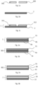
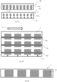
- Fig. 1a shows two donor foils 301, 302. It is possible here that at least one of the donor foils 301, 302 is a donor transfer foil, preferably a hot stamping, cold stamping, and/or a thermal transfer foil, and/or is a donor laminating foil. It is also possible for the dispenser films 301, 302 to be designed in the same way and/or different from one another.
- the donor films 301, 302 each comprise one or more assistant layers 11a, at least one decorative layer 4a, a delamination layer and/or at least one functional layer 5a.
- Fig. 1b shows a receiver film 2. It is possible that the receiver film is a receiver transfer film, preferably a hot stamping film or cold stamping film or thermal transfer film, or that the receiver film 2 is a receiver laminating film.
- the receiver film is a receiver transfer film, preferably a hot stamping film or cold stamping film or thermal transfer film, or that the receiver film 2 is a receiver laminating film.
- the receiver film 2 may comprise a receiver carrier layer 21, a decorative layer 4b, a delamination layer and/or a functional layer 5b.
- a decorative layer 4a, 4b each has one of the following or a combination of the following layers, in particular over the entire area and/or part of the area: one or more lacquer layers, one or more layers containing a liquid crystal material, one or more layers containing a thin film system, one or several metallic layers, one or more volume hologram layers, one or more layers having an optically active surface structure or an optically active surface relief, one or more reflection layers 10a, 10b.
- the receiver film 2 prefferably has one or more assistance layers 11b.
- An assistance layer 11a, 11b in particular has one of the following or a combination of the following layers: One or more adhesion promoter layers, one or more release layers, one or more protective layers and/or one or more pressure-receiving layers.
- Fig. 1c shows an example of a film intermediate product 1 comprising the in Fig. 1b receiver film 2 shown and two film elements 311, 312, each of which is formed by a section of the in Fig. 1a Donor films 301, 302 shown are formed and which are applied to the receiver film 2.
- Fig. 1a to Fig. 1c thus show a process for producing an intermediate film product 1.
- Fig. 1b shows step a), providing a receiver film 2.
- Fig. 1a shows step b), providing one or more donor films, with two donor films 301, 302 in particular being provided here.
- Fig. 1c shows the application of one or more film elements, which are each formed by a section of one of the one or more donor films, onto the receiver film 2 Fig. 1 a , whereby in particular the film elements 311, 312 are each formed by a section of the donor films 301, 302.
- the steps can be carried out in particular simply and/or multiple times in any order, preferably in the order mentioned above.
- a film element 311, 312 is formed by a section of a donor transfer film, in particular a section of a hot stamping film, a cold stamping film and/or a thermal transfer film. It is also possible for a film element 311, 312 to be formed from a section of a donor laminating film.
- the section of a donor film forming a respective film element 311, 312 may include the entire donor film 301, 302 or only a part and/or several parts of a donor film 301, 302.
- the intermediate film product 1 viewed perpendicular to a plane spanned by the intermediate film product, preferably in a top view based on the sectional view shown here, has at least two, preferably different, directly adjacent, at least partially overlapping and/or adjacent film elements, which during production on a film would be incompatible and/or at least would mean an increase in manufacturing time, a reduction in the quality of the features and/or higher rejects and/or higher manufacturing costs.
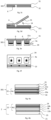
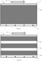
- Fig. 2a shows a receiver film 2, which comprises a receiver carrier layer 21, a decorative layer 4b and a functional layer 5b.
- the receiver carrier layer 21 preferably consists of PET, BOPP, PEN, PMMA, PC, ABS, PU, PVC and/or glass, and in particular has a layer thickness of 5 ⁇ m to 150 ⁇ m, preferably 10 ⁇ m to 75 ⁇ m.
- the decorative layer 4b is here, for example, arranged between the receiver carrier layer 21 and the functional layer 5b. It is also possible for the functional layer 5b to be arranged between the decorative layer 4b and the receiver carrier layer 21.
- the receiver film 2 prefferably has at least one delamination layer 18 and/or at least one assistant layer 11b.
- Fig. 2b shows a donor film 3, which includes a donor carrier layer 31, a decorative layer 4a and a functional layer 5a.
- the donor carrier layer 31 preferably consists of PET, BOPP, PEN, PMMA, PC, ABS, PU, PVC and / or glass, and in particular has a layer thickness of 5 ⁇ m to 150 ⁇ m, preferably 5 ⁇ m to 75 ⁇ m, more preferably 5 ⁇ m to 50 ⁇ m.
- the decorative layer 4a is here, for example, arranged between the donor carrier layer 31 and the functional layer 5a. It is also possible for the functional layer 5a to be arranged between the decorative layer 4a and the donor carrier layer 31.
- the donor film 301 may have at least one delamination layer 18 and/or at least one assistant layer 11b.
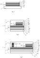
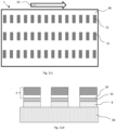
- Fig. 3a shows a donor film 301 comprising a donor carrier layer 31, a donor transfer layer 32 and a donor release layer 33.
- the donor release layer 33 is preferably arranged between the donor carrier layer 31 and further layers of the donor film 301.
- the donor transfer layer 32 preferably comprises one or more of the above-described assistant layers 11a, decorative layers 4a, functional layers 5a and/or delamination layers 18.
- the donor release layer 33 has the properties of a release layer.
- a release layer includes in particular one or more wax layers.
- a release layer preferably has an adhesive layer.
- the donor carrier layer 31 can be removed from the donor transfer layer 32 by the donor release layer 33.
- the donor carrier layer 31 can be separated from the donor transfer layer 32 in particular in a non-destructive manner. It is also possible for a film element 311, 312 transferred by means of the donor transfer layer 32 to be shaped during detachment.
- Fig. 3b shows a receiver film 2 comprising a receiver carrier layer 21, a receiver transfer layer 22 and/or a receiver release layer 23.
- the receiver release layer 23 is preferably arranged between the receiver carrier layer 21 and further layers of the receiver film 2.
- the receiver transfer layer 22 preferably comprises one or more of the above-described assistant layers 11a, decorative layers 4b, functional layers 5b and/or delamination layers 18.
- the receiver transfer layer 22 may have a transparent layer, in particular a layer that is transparent to the human eye at least in a partial area in the UV range with a wavelength of 400 nm to 240 nm and/or a color layer, which is preferred is printed.
- the receiver carrier layer 21 can be removed from the receiver transfer layer 22 by the receiver release layer 23.
- the receiver carrier layer 21 can therefore be separated from the receiver transfer layer 22 in a non-destructive manner.
- the receiver transfer layer 22 is particularly possible for the receiver transfer layer 22 to be shaped when the receiver transfer layer 22 is detached from the receiver carrier layer 21.
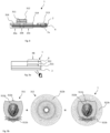
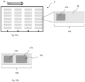
- Fig. 3c shows a donor film 301 with a donor transfer layer 32 and a donor carrier layer 31.
- the donor film 301 or the donor carrier layer 31 has a recess 6, which is introduced through the donor transfer layer 32 and partly into the donor carrier layer 31.
- the donor film 301 has a void and/or a complete and/or partial severance 7a of the donor carrier layer 31 and/or the donor transfer layer 32 and/or has additional severances 7a and/or recesses 6 of the donor carrier layer 31 and/or the donor transfer position 32.
- Fig. 3d shows a dispenser film 301, which in Fig. 3c was described.
- the donor film 301 is a donor transfer film and the donor transfer layer 32 can be removed from the donor carrier layer 31.
- the donor film 301 or the donor carrier layer 31 has an optional recess 6, which is introduced into the donor transfer layer 32 and partly into the donor carrier layer 31.
- the donor film 301 is connected here, for example, to a receiver film 2.
- the donor carrier layer 31 is preferably detached from the donor transfer layer 32 at least partially, whereby in particular a first partial area of the donor transfer layer 32 remains as a film element 311 on the recipient film.
- the donor film 301 is a donor transfer film, which is in particular a hot stamping film
- the receiver film 2 is a receiver transfer film, which is in particular a hot stamping film.
- Further film elements are preferably formed from sections of the donor film 301, which is a donor transfer film, and/or from further one or more donor films 302, 303, 304.
- Rollers are preferably used to adjust the take-off angle 14.
- pulling off the dispenser film 301 over an edge has proven to be useful.
- Particularly advantageous are very tapered edges, preferably with a small angle between the surfaces, since they allow, for example, a narrowly localized take-off location with a large take-off angle, preferably up to 180°.
- Mechanical separation aids are preferably used to break up the donor transfer layers 32 with sharp edges.
- a withdrawal angle 14 is set between 30° and 180°, preferably 90° and 180°.
- a lower detachment force for detaching the donor carrier layer 31 from the donor transfer layer 32 applied to the receiver film 2 is achieved than without recesses 6, severances 7a, 7b and/or empty spaces and/or at different take-off angles.
- relatively low thermal and/or mechanical loads are realized on the donor transfer layers 32 and/or the receiver film 2, which is preferably a receiver transfer film, preferably a hot stamping film.
- step c Through suitable process control, in particular with cold stamping and/or hot stamping, in step c), it has surprisingly been shown that even donor transfer layers 32 with relatively high release forces can be applied to a receiver film 2, which is preferably a receiver transfer film, whose receiver transfer layers are low Have detachment forces without the receiver transfer layer 22 being detached or detached from the receiver carrier layer 21 and/or a desired function in the film intermediate product 1 being lost, for example the function of a delamination layer.
- Fig. 3e shows an example of a donor film 301 with a donor carrier layer 31, a further donor carrier layer 31a and a donor transfer layer 32, with recesses 6 being made in the further donor carrier layer 31a, so that the donor film 301 is preferably like that in Fig. 3d dispenser film 301 described a receiver film 2 is applied and the donor carrier layer 31 and/or the further donor carrier layer 31a is advantageously detached.
- the donor transfer layer 32 further comprises a donor adhesive layer 34, which preferably serves to apply the respective donor transfer layer 32, which preferably forms a section of the donor foil 301 forming one or more foil elements 311 to 314, to the recipient foil 2.
- the donor transfer layer 32 preferably has a decorative layer 4a, which is formed, for example, by a printing layer.
- the further donor carrier layer 31a prefferably be designed to be detachable from the donor carrier layer 31, such that the further donor carrier layers 31a, preferably after the respective donor film 301 has been applied to a receiver film 2 and after the donor carrier layer 32 has subsequently been detached from one at least in some areas or several first partial areas of the respective donor transfer layer 32, remain as film elements on the receiver film 2.
- the donor film 301 with the further donor carrier layer 31a to form voids at the locations of the recesses 6, the further donor carrier layer 31a with the voids being applied to the donor carrier layer 31, preferably with a donor transfer layer 32 arranged on the further donor carrier layer 31a .
- the donor carrier layer 31 and/or the further donor carrier layers 31a are a PET carrier.
- Fig. 3f shows as an example the in Fig. 3e Dispenser foil shown in view from below.
- Register marks 13 are also applied here as an example.
- Fig. 4a shows an example of a donor film 301 with a donor carrier layer 31, a donor release layer 33 and a donor transfer layer 32, which has an optional donor adhesive layer 34, the donor adhesive layer 34 preferably being a heat-seal adhesive layer which is activated by means of pressure and heat.
- the pressure and heat in step c) are generated by hot stamping using a heated embossing stamp.
- the donor transfer layer 32 has a decorative layer 4a, preferably with a replication layer 9a, into which in particular at least one optically active surface structure is introduced, and which is preferably arranged between the optional donor adhesive layer 34 and the donor release layer 33.
- the decorative layer 4a has a reflection layer 10a between the replication layer 9a and the optional donor adhesive layer 24, preferably a metallic reflection layer, which is in particular partially applied, preferably at least partially applied to the at least one optically active surface structure of the replication layer 9a.
- the donor transfer layer prefferably has an assistant layer 11a between the donor release layer 33 and the replication layer 9a.
- assistant layer 11a between the donor release layer 33 and the replication layer 9a.
- Fig. 4b shows an example of a receiver film 2 with a receiver carrier layer 21, a receiver release layer 23 and a receiver transfer layer 22, which in particular has a receiver adhesive layer 24.
- the receiver transfer layer 22 in particular has a decorative layer 4b, preferably with a reflection layer 10b, which preferably has an HRI layer and/or has a partially transparent HRI layer, and which is arranged between the optional receiver adhesive layer 24 and the receiver release layer 23.
- the decorative layer 4b preferably has a replication layer 9b, into which in particular at least one further optically active surface structure is introduced and which is arranged between the reflection layer 10b and the receiver release layer 23.
- the receiver transfer layer 22 also preferably has an assistant layer 11b between the replication layer 9b and the receiver release layer 23.
- the receiver transfer layer 22 forms a diffractive feature, preferably a diffractive security feature.
- the reflection layer it is also possible for the reflection layer to have a thin film system.
- the receiver film 2 is a receiver transfer film, the receiver transfer layer 22 being removable from the receiver carrier layer 21, the detachment or separation of the receiver transfer layer 22 from the receiver carrier layer 21 being ensured preferably by a release layer 23, which comprises one or more wax layers.
- the reflection layer 10b is preferably at least partially applied to the at least one further optically active surface structure of the replication layer 9b.
- a receiver adhesive layer 24 is preferably arranged on the reflection layer 10b, preferably a heat seal adhesive layer, which is activated by means of pressure and heat.
- the pressure and heat in step c) are generated by hot stamping using a heated embossing stamp.
- the receiver adhesive layer 24 prefferably has an adhesion promoter layer, which preferably serves to improve the connection of the receiver adhesive layer 24 to the reflection layer.
- the receiver adhesive layer 24 is applied in particular partially, preferably applied individually to one or more first partial areas.
- the receiver adhesive layer 24 is radiation curable.
- step c) is preferably carried out by cold stamping, with the one or more donor films being connected to the recipient adhesive layer 24 and the adhesive being hardened by means of radiation.
- the donor transfer layers arranged in the one or more first partial areas on which the receiver adhesive layer 24 is arranged expediently remain adhered to the receiver film 2 as film elements 311 to 314.
- Fig. 5 shows as an example the in Fig. 4a Donor transfer layer 32 shown, which is applied to a receiver film 2 and thus forms a section of the donor film 301 forming a film element 311.
- an upper assistant layer 11a can be provided on the donor transfer layer 32 and/or the film element 311, which is arranged on the outermost side facing away from the receiver film 2.
- the upper assistant layer 11a has an adhesive layer, which is preferably an adhesive layer of the donor release layer 33 of the respective donor film 301, which forms the film element 311.
- the donor release layer 33 further has at least one wax layer, so that when the donor carrier layer 31 is detached from the donor transfer layer 32, this adhesive layer remains on the donor transfer layer 32 and as a layer of the film element 311 on the receiver film 2.
- This adhesive layer then serves in particular to connect the intermediate film product 1 to a target substrate.
- the shape of the applied film element 311 is determined in particular by the shape of the embossing die during hot stamping in step c).
- the shape of the applied film element 311 is determined by the fact that the adhesive layer is printed during cold stamping in step c), in particular that in step c) on the donor film 301 and / or on the receiver film 2 in one or An adhesive layer is printed on several first subregions 20b, in particular by means of a digital printing process, but is not printed on in one or more second subregions.
- the shape of the film element 311 is determined by recesses 6, severances 7a, 7b and/or voids, as shown in particular in Fig. 3d, Fig. 3e and Fig. 3f is described.
- the receiver film 2 prefferably be a receiver transfer film with a receiver transfer layer 21, with the film element 311 or further film elements being applied to the receiver transfer layer 21.
- Fig. 6 shows an example of a film intermediate product 1, with a film element 311 made from a section of a film as in Fig. 5 described donor transfer layer 32 to one as in Fig. 4b receiver film 2 described is applied.
- a further adhesive layer 8 is applied to the receiver film 2 and the donor transfer layer 32 or the film element 311, which has one or more layers and is preferably used to connect the film intermediate product 1 to a target substrate.
- the softening temperature of the donor adhesive layer 34 and the recipient adhesive layer 24 differs, and/or that the softening temperature of the donor adhesive layer 34 and/or the softening temperature of the recipient adhesive layer 24 differs from the softening temperature of the further adhesive layer 8, in particular that the Softening temperature of the donor adhesive layer 34 is at least 2.5 ° C below the softening temperature of the recipient adhesive layer 24, preferably at least 5 ° C below, preferably at least 7.5 ° C below.
- the softening temperature of the further adhesive layer 8 is at least 2.5 ° C below the softening temperature of the donor adhesive layer 34 and / or the recipient adhesive layer 24, in particular at least 5 ° C below, preferably at least 7.5 ° C falls below and/or that a softening of the further adhesive layer 8 is carried out, wherein the temperature of the donor adhesive layer 34 and / or the recipient adhesive layer 24 is at least 2.5 ° C lower, in particular at least 5 ° C lower, preferably at least 7.5 ° C lower than the softening temperature of the respective donor adhesive layer 34 or receiver adhesive layer 24.
- the donor adhesive layer 34 prefferably crosslinked chemically and/or by radiation, in particular after step c), and/or for the softening temperature of the donor adhesive layer 34 and/or recipient adhesive layer 24 to be increased after step c).
- Fig. 7 shows an example of a film intermediate product 1, which in addition to that in Fig. 6 shown film intermediate product 1, has a further film element 312.
- This film element 312 has, in particular in addition to that in Figure 5 described film element 311, a functional layer 5a.
- film elements which preferably have a decorative layer 4a, a functional layer 5a, an assistant layer 11a and/or a delamination layer 18, to be applied to the receiver film 2, preferably in any arrangement.
- a film element 314 it is also possible for a film element 314 to have a print layer with luminescent, preferably fluorescent, dyes.
- an intermediate film product 1, which has at least one functional layer 5a, 5b, is applied by injecting an injection molding compound onto the target substrate, with the injection molding compound in particular forming the target substrate.
- the intermediate film product 1 is preferably used as an insert sheet, in particular with a width of 10 mm to 800 mm, a length of 15 mm to 1200 mm and a thickness of 20 ⁇ m to 300 ⁇ m.
- Fig. 8 shows an example of a possible arrangement of film elements 311 to 314 on the receiver film.
- a section 7a and a recess 6 of a film element 313 are also shown as an example.
- a donor carrier layer 31 of a donor film 304 not shown here, to be detached in such a way that when the donor carrier layer 31 is detached at least in areas, first partial areas 20a remain as foil elements 314 on the receiver foil 2 and optionally second partial areas 20b of the donor transfer layer 32 with the Donor carrier layer 31 can be deducted.
- the film elements 314 are preferably similar and/or different from one another. It is also possible for the film elements 314 to be arranged, for example, in a regular one- or two-dimensional grid.
- severances 7a, 7b and/or recesses 6 are introduced, with the severances 7a, 7b and/or recesses 6 preferably being between the first and second portions 20a, 20b of the respective donor transfer layer 32 are introduced.
- Fig. 9a shows an example of a film intermediate product 1, which has a film element 311 applied to a receiver film 2.
- a further film element 312 is arranged on this film element 311.
- a further adhesive layer 8 is applied, which is preferably applied to the two film elements 311 and 312. Furthermore, it is particularly possible for the further adhesive layer 8 to also be in contact with the receiver film 2.
- the receiver film 2 is preferably non-removable, preferably non-removable and at least partially transparent, preferably at least partially transparent in the UV range and/or a range visible to the human eye.
- the receiver film 2 is at least partially removable, preferably that the receiver film 2 has a removable receiver carrier layer 21.
- a film element 311 is partially overlapped by another film element 312.
- the partially overlapped film element 311 completely and/or partially overlaps the other film element 312.
- optical effects of the further film element 312 are at least partially visible through the partially overlapped film element 311, preferably at least partially visible to the human eye.
- the partially overlapped film element 311 has a replication layer at least in an area overlapped by the further film element 312.
- the partially overlapped film element 311 preferably has a layer on its side facing away from the receiver film 2, which has one of the Receiver film 2 facing side of the further film element 312 is in contact, whereby a contact area KB is formed.
- the refractive index difference is preferably less than or equal to 0.2, preferably less than 0.1.
- the refractive index difference is less than 0.2, preferably less than 0.1. This is at least in 50% of the contact area KB.
- an HRI layer and/or a metal layer is provided in the remaining areas of the contact area KB.
- the refractive index difference is greater than 0.3, preferably greater than 0.5, with an HRI layer being provided in particular.
- Fig. 9b shows a concrete design example that includes the structure Fig. 9a can be realized.
- the film element 312 prefferably be applied to a receiver film 2 and for the film element 311 in the film intermediate product 1 to be applied to the receiver film 2, and in particular the film element 312, in such a way that it partially overlaps with the film element 312.
- the receiver film 2 is expediently preferably transparent and/or in particular not shown here.
- the film intermediate product 1 in particular starting from Fig. 9a shown in bottom view.
- a viewer thus looks, in particular when viewed vertically on a plane spanned by the film intermediate product 1, through the receiver film 2 and/or through the receiver carrier layer 21 and/or through the receiver transfer layer 22, onto the film elements 311, 312 of the film intermediate product 1.
- the decorative layer 4a of the film element 311 has several layers 311b provided over part of the surface.
- the layers 311b provided over part of the surface are each preferably arranged in a pattern, the patterns being in particular in the form of a coat of arms, a lion's head and a banner with the word "Kinegram”.
- a reflection layer in particular a metallic reflection layer, for example made of aluminum, is expediently arranged on the layers 311b provided over part of the area, the reflection layer preferably being arranged only in the layers 311b provided over part of the area.
- the layers 311b provided over part of the area preferably have optically variable effects.
- the layers provided over part of the surface expediently each comprise optically active surface structures, which in particular have microstructures.
- the film element 311 preferably has a coloring.
- the coloring is preferably formed by a translucent lacquer layer, which is expediently arranged between the receiver film 2 and the partially provided layers, so that the partially provided layers 311b for example, appear in gold colors, especially when looking at the foil element 311 in the product 100.
- the film element 311 and/or the receiver film 2 is transparent or semi-transparent at least over part of the surface.
- the decorative layer 4a of the film element 311 has a transparent or semi-transparent layer, which is in particular a lacquer layer, which is arranged at least outside the layers provided over part of the surface.
- the decorative layer 4a of the film element 311 may have a transparent or semi-transparent layer, which is in particular a lacquer layer, and/or a further transparent or semi-transparent layer, which is in particular a lacquer layer, which is arranged on the layers provided over part of the surface is.
- the receiver film 2 in particular the receiver transfer layer 22 and/or the receiver carrier layer 21, has a transparent or semi-transparent layer, which is in particular a lacquer layer or a plastic layer.
- areas of the film element 312 which do not overlap with the reflection layer of the film element 311 are recognizable to the viewer, in particular when viewed perpendicularly to a plane spanned by the film intermediate product 1, in particular in the film intermediate product 1 and / or in the product 100.
- the film element 312 preferably has optically variable effects.
- the film element 312 has a decorative layer 4a with a partial surface provided layer 312b, which preferably comprises a metal layer, for example made of aluminum, and serves in particular as a reflection layer.
- the layer 312b provided over part of the area is expediently arranged in a pattern; the layer 312b provided over part of the area preferably forms partially metallized lines.
- the partially metallized lines preferably form a guilloche.
- Optically active surface structures in particular microstructures, are expediently provided in the partial area layer 312b of the film element 312.
- the optically active surface structures in particular the microstructures, produce, for example, a sequential lighting of the lines, in particular as an apparent movement effect.
- the coloring of the film element 311, in particular the translucent lacquer layer of the film element 311, is not present in the partial surface layer 312b of the film element 312, in particular the partially metallized areas of the film element 312, the partial surface layer 312b of the film element 312 appears in a different color than the partially provided layers 311b of the film element 311.
- the guilloche of the film element 312 appears silver.
- Fig. 10a shows a possible step a), providing a receiver film 2, in a top view.
- the receiver film 2 is provided with the running direction 19 shown, preferably in a roll-to-roll process.
- the receiver film 2 already has decorative layers 4b.
- the receiver film 2 has register marks 13, which are in particular printed, diffractive and/or partially metallized, for register-accurate application of further layers and/or one or more film elements 311, 312, 313, 314. It is also possible for register marks to be arranged transversely to the running direction 19. It is also possible for layers of the receiver film 2 to take on the function of register marks, preferably diffractive elements of the receiver film 2. It is also possible for the receiver film 2 to have one or more decorative layers 4b, functional layers 5b and/or delamination layers.
- Fig. 10b shows a possible step c), an application of one or more film elements 311, 312, 313, 314, which is or are each formed by a section of one of the one or more donor films 301, 302, 303, onto the receiver film 2
- the film intermediate product 1 shown is produced, which has an example in Fig. 10a receiver film 2 described and various film elements 311, 312, 313, 314.
- the film elements 311, 312, 313, 314 are preferably applied in register.
- An intermediate film product 1 preferably has film elements 311, 312, 313, 314 that are similar and/or different from each other transversely to the running direction 19.
- the receiver foil 2 is a hot stamping foil and for step c) to be carried out by means of hot stamping, expediently at least one of the one or more donor foils 301 to 304 being a hot stamping foil.
- Fig. 10c shows a possible step b) of producing an intermediate film product 1, providing one or more donor films 301, 302, which are used, for example, for applying the in Fig. 10b shown film elements 311, 312, 313, 314 are provided.
- the donor films 301, 302 are provided in strips, for example. It is particularly possible for further donor films 303, 304 to be provided and/or for further film elements to be applied.
- step c) a step c1), bringing one or more donor films 301, 302 into contact with the receiver film 2, is carried out.
- step c2) it is further possible for a step c2) to be carried out, an at least partial detachment, in particular mechanical separation, of the donor carrier layer 32 from one or more first partial areas 20a of the respective donor transfer layer in such a way that the one or more first partial areas 20a remain on the receiver film 2 as film elements 311, 312, 313, 314.
- step c3) includes pulling off the respective donor carrier layer 31 with one or more second partial areas 20b of the respective donor transfer layer 32 from the one or more film elements 311 to 314.
- the dispenser film 302 shown above has cutout areas 311a, from which in particular the in Fig. 10b described film elements 312, 313, 314 are applied to the receiver film 2.
- the application to the receiver film 2 is carried out with a donor film 302 of the type shown above, preferably by means of a forming stamp, in particular with hot stamping.
- the pressure and heat required for hot embossing are generated in step c) by means of hot embossing using a heated embossing die.
- the dispenser film 301 shown below has cutout areas 311a, from which in particular the in Fig. 10b Film elements 311 described are applied to the receiver film 2.
- the donor film 301 preferably has at least partial cuts 7a, which enclose the cutout areas 311a.
- the cuts 7a are preferably made by punching.
- the application of the film elements 311 to 314 onto the receiver film 2 is carried out in the case of a donor film 302 of the type shown below, preferably by means of an embossing stamp, in which the shape of the stamp can be larger than that of a forming stamp, which is the same when applying a film element with the above Donor film 302 shown would be used to apply comparable film elements to the receiver film 2.
- the pressure and heat required for hot embossing are generated in step c) by means of hot embossing using a heated embossing die.
- a radiation-curable adhesive layer to be printed onto the receiver film 2 and/or one of the donor films 301, 302, in particular to be partially applied, preferably to be applied individually to one or more first partial areas.
- step c) is preferably carried out by means of cold stamping, whereby the one or more donor films 301, 302 are connected to the receiver film 2 and the adhesive is hardened by means of radiation.
- the respective donor carrier layer 31 is removed, the sections of the respective donor transfer layers 32 arranged in the one or more first subregions 20a on which the adhesive layer is arranged remain adhere to the receiver film 2 as film elements 311 to 314.
- Optional adhesion promoter layers on the receiver film 2 and/or at least one of the one or more donor films 301, 302 preferably secure the bond between the individual layers of the receiver film 2, the receiver transfer layer 22, at least one of the one or more donor films 301, 302 and/or the respective donor transfer layers 32.
- a web has similar and/or different cutout regions 311a to 314a and/or cutouts of the one or more donor films 301, 302 in the running direction 19 and/or transversely to the running direction 19.
- a donor film 301, 302 only covers an area of 0.2% to 20% in a top view or when viewed vertically on the respective donor film 301, 302 and the respective receiver film 2. , preferably an area of 0.5% to 5% of the receiver film 2.
- the donor films preferably have register marks 13, which enable the one or more film elements 311, 312, 313, 314 to be applied to the receiver film 2 in precise register.
- the two webs or the two dispenser films 301, 302 are preferably fed separately. In particular, the two dispenser films 301, 302 are manufactured separately.
- Fig. 10d shows a receiver film 2 with donor films 301, 302, 303 provided in strips.
- the application of the one or more film elements 311, 312, 313 is preferably carried out in register in the running direction 19 and/or transversely to the running direction 19.
- the web lines of the respective donor films 301 to 303 and/or the receiver film 2 are preferably adjusted for a register-accurate application of the film elements 311, 312, 313 to the receiver film 2.
- the feed distance of the receiver film 2 and/or the respective donor film 301, 302, 303 may be set for register-accurate application of the film elements 311, 312, 313 to the receiver film 2.
- the width of the strip of one of the one or more donor films 301, 302, 303 perpendicular to the running direction 19 varies over the length of the strip in the running direction 19, preferably that the outline shape of one of the one or several donor films 301, 302, 303 is at least partially non-linear, preferably wave-shaped.
- the shape design in particular the shape design of at least one film element 311, 312, 313, is carried out, for example, by partial pressure during cold stamping, an only partially applied hot stamping adhesive, and/or during hot stamping due to the shape of the stamping tool. It is also possible for the shape to be created by cutting the dispenser film 301, 302, 303.
- the extent of a film element 311, 312, 313, in particular a strip-shaped film element 311, 312, 313, is determined in strip form by the previous cutting of the respective dispenser film 301, 302, 303.
- the outline shape of one of the one or more film elements 311, 312, 313, which is preferably formed by a section of a strip-shaped dispenser film 301, 302, 303, runs in the form of lines, motifs and/or text.
- one or more of the one or more dispenser films 301 to 303 and / or one or more of the one or more film elements 311, 312, 313 has recesses and / or is interrupted, preferably by means of recesses 6, severances 7a and / or voids, like in particular Fig. 3c to Fig. 3f is described.
- the width of the strip of one of the one or more film elements 311, 312, 313, preferably perpendicular to the running direction 19, is in a width range of 0.5 mm to 10 mm, preferably of 1 mm to 5 mm.
- the width of the strip is one of the one or more film elements 311, 312, 313 for example, locally in the mentioned latitude range and preferably deviates locally from it.
- Fig. 10e shows by way of example a separation after step c), in particular by cutting and/or punching, of the receiver film 2 with the one or more film elements 311 to 314.
- the receiver film 2 with the film elements 311 to 314 preferably becomes a strip-shaped web and/or preferably several strip-shaped webs are cut, each of which preferably forms an intermediate film product 1.
- a single or multi-layer further adhesive layer 8 is preferably applied to the receiver film 2 and/or the one or more film elements 311 to 314.
- At least one layer of the further adhesive layer 8 is formed from the donor release layer 33.
- the further adhesive layer 8 is applied in such a way that differences in thickness of the intermediate film product 1 are at least partially compensated for.
- the width of the strip of the film intermediate product 1 varies over the length of the strip, preferably that the outline shape of the film intermediate product is at least partially non-linear, preferably wavy.
- the intermediate film product 1 prefferably to be applied to a target substrate in order to produce a product, preferably in a laminator, a hot stamping device, a cold stamping device and/or applied to a target substrate in an application system.
- the film intermediate product 1 prefferably be applied by injecting an injection molding compound onto the target substrate, in particular where the injection molding compound forms the target substrate. It is particularly possible here for the intermediate film product 1 to be deformed beforehand, in particular to be deep-drawn.
- the intermediate film product 1 is preferably applied as an insert sheet to an injection molding compound and has a width in the range of 10 mm to 800 mm and a length in the range of 15 mm to 1200 mm.
- the thickness of the intermediate film product 1 is preferably 20 ⁇ m to 300 ⁇ m, the thickness varying in particular over the width and length of the intermediate film product 1.
- the intermediate film product 1 is preferably applied to a porous target substrate, such as paper, which absorbs the adhesive differently depending on the local pressure, so that more adhesive penetrates into the target substrate in areas of the intermediate film product 1 with greater thicknesses. This in particular prevents any disruptive steps from being visible on the surface of the product due to the different thicknesses.
- a porous target substrate such as paper
- the surface can be leveled by allowing the adhesive to flow when applied to the target substrate.
- the intermediate film product 1 is used to produce a surface of the product and is applied to a target substrate, for example a paper, a cardboard, a plastic film, a substrate made of one or more plastic and/or paper layers, a substrate comprising one or more decorative layers and/or or a carrier layer is applied.
- a target substrate for example a paper, a cardboard, a plastic film, a substrate made of one or more plastic and/or paper layers, a substrate comprising one or more decorative layers and/or or a carrier layer is applied.
- the total thickness of the single or multi-layer further adhesive layer 8 is preferably more than the maximum difference in thickness between the areas with the one or more film elements 311 to 314 and those areas without film elements 311 to 314, thus the contours of the film elements 311 to 314 on the surface are not clearly visible.
- the total thickness of the single or multi-layer further adhesive layer 8 is preferably more than the difference between the largest thickness of the intermediate film product 1 and the smallest thickness of the intermediate film product 1, so that the contours of the film elements 311 to 314 are not clearly visible on the surface.
- the thickness of the further adhesive layer 8 is applied, in particular partially, such that it is thicker in the areas of the receiver film 2 without film elements 311 to 314 and/or in regions with the lowest thickness of the intermediate film product than in the regions of the receiver film 2 with film elements 311 to 314 and/or in areas with the greatest thickness of the film intermediate product 1.
- An additional auxiliary layer which expediently forms a layer of the single or multi-layer adhesive layer 8, is preferably applied partially in register, which compensates for differences in thickness of the intermediate film product 1.
- the single or multi-layer further adhesive layer 8 is then preferably applied in a homogeneous layer thickness.
- at least one layer of the further adhesive layer 8 is applied in a homogeneous layer thickness.
- the adhesive is thermally relatively stable after curing and/or only comparatively little heat and pressure is introduced during transfer to the target substrate.
- Fig. 11a shows an example of a receiver film 2 with a surface-transferred film element 311.
- the donor film 301 is a donor transfer film.
- the receiver film 2 also has a delamination layer 18.
- a delamination layer that allows local partial delamination to serve as protection against manipulation is particularly advantageous. It is also possible for the donor film 301 to have a delamination layer 18.
- the thickness of the donor transfer layer 32 is in a range from 1 ⁇ m to 15 ⁇ m, preferably in a range from 2 ⁇ m to 10 ⁇ m.
- the thickness of the receiver carrier layer is preferably in a range from 5 ⁇ m to 150 ⁇ m, preferably in a range from 10 ⁇ m to 50 ⁇ m.
- the advantage here is that features on transfer films are manufactured independently of the properties and/or process capability, preferably the manufacturing requirements, of the delamination layer.
- This preferably produces a combination of optical effects, which are provided in particular with the one or more donor films 301 to 304, with the function of a delamination layer, which is provided in particular by the delamination layer 18 of the receiver film 2.
- a combination is not possible when produced on a film and/or can only be produced with higher costs, more rejects, poorer protection against counterfeiting and/or poorer quality.
- a film element 311 to 314 has optical effects that have a very high replication quality, which requires high temperatures and high pressure. However, due to the high pressure and high temperatures, the delamination layer would be damaged if manufactured on the same film.
- Fig. 11b shows an example of a receiver film 2 with film elements 311, 312, 313 transferred in strips.
- the donor film 301 is a donor transfer film.
- the receiver film 2 also has a delamination layer 18. It is also possible for the donor film 301 to have a delamination layer 18.
- Fig. 11c shows a film intermediate product 1 in a top view, which has several labels 15.
- the labels 15 each include at least one section of the receiver film 2 and at least one film element 311 to 314.
- Fig. 11d shows that in Fig. 11c Illustrated film intermediate product 1 in a schematic sectional view.
- the receiver film 2 is preferably applied to a carrier 40, in particular a siliconized carrier.
- PSA Pressure Sensitive Adhesive
- the receiver film 2 with the applied film elements 311 to 314 by means of the further Adhesive layer 8 is laminated onto the carrier 40, and that optionally the receiver film 2 is punched and weeded.
- the receiver film 2 is punched and weeded before being connected to the carrier 40 and/or punched and weeded after being connected to the carrier 40.
- the labels 15 can be removed from the carrier 40 in a non-destructive manner using the PSA adhesive layer.
- the further adhesive layer 8 which is in particular a PSA adhesive layer, to be applied to the carrier 40, the receiver film 2 and/or partial areas of the receiver film 2.
- one or more labels 15 are detached from the carrier 40 and applied to a further object, the delamination layer 18 being intended to cause the label 15 to delaminate and/or tear when the label 15 is attempted to be detached from the further object Layers of the label 15 effects.
- Fig. 12a shows an example of the provision of a receiver film 2, which is in particular a receiver laminating film with a receiver carrier layer 21, and an enlarged view of a feature area MB of a decorative layer 4b, which is preferably arranged on the receiver carrier layer 21 of the receiver film 2.
- the decorative layer 4b preferably has at least one feature area MB, in particular a plurality of feature areas MB.
- the decorative layer 4b preferably forms one or more security features using the feature areas MB.
- a feature area MB preferably has at least one first decorative element 17b.
- several feature areas MB and/or several first decorative elements 17b are provided in a regular one- or two-dimensional grid.
- the decorative layer 4b in the feature areas MB further has an at least partially transparent layer, at least one at least partially designed transparent reflection layer and/or at least one at least partially designed metallic reflection layer and/or an at least partially designed print.
- the receiver film 2 prefferably has an assistant layer 11b, in particular an adhesion promoter layer.
- register marks it is also possible for register marks to be provided on the receiver film 2.
- an intermediate film product 1 is thus produced, which is used to produce a security document, in particular a banknote.
- Fig. 12b shows an example of one in Fig. 12a enlarged feature area MB of the receiver film 2, wherein a second decorative element 17a is applied, which is formed by a film element 311, the film element 311 being formed by a section of one of the one or more donor films 301 to 304, which is in particular a donor transfer film.
- the second decorative element 17a differs from the first decorative element 17b.
- the film element 311 preferably has a printing layer, in particular a lacquer layer, and/or a diffraction-optical element, which consists of a replication layer with a molded diffractive surface structure, which is covered at least in partial areas by a reflection layer.
- first and second decorative elements 17a, 17b can at least partially overlap one another and/or one another and/or for further decorative elements to be applied which overlap one another and/or to overlap the first and/or second decorative elements 17a, 17b .
- the intermediate film product 1 preferably points, preferably when viewed perpendicularly, on a plane spanned by the intermediate film product, preferably as in the Fig. 12b shown top view, at least two different directly adjacent, at least partially overlapping and / or adjacent decorative elements. These are preferably each formed by at least one film element 311, 312 and/or by the receiver film 2.
- the receiver film 2 and the one or more donor films 301, 302 are preferably supplied separately.
- the donor films 301, 302 and the receiver film 2 are manufactured separately.
- the decorative elements 17a, 17b preferably each consist of areas of the decorative layer 4a, 4b of the receiver film 2 and/or the one or more donor films 301 to 304, which differ from the surrounding areas in a contrasting manner.
- a lacquer layer of the decorative layer in the area of the decorative elements is colored differently than the surrounding areas and/or is only provided in the area of the decorative elements.
- a surface structure, for example a diffractive surface relief, of the decorative layer 4a, 4b can only be provided in the area of the decorative elements 17a, 17b or can have a different surface relief than the surrounding areas.
- a metallic reflection layer of the decorative layer 4a, 4b can only be provided in the area of the decorative elements 17a, 17b but not in the surrounding areas.
- the decorative layer 4a, 4b is preferably designed to be transparent in the area outside the decorative elements 17a, 17b.
- a functional layer 5a, 5b of the one or more donor films 301 to 304 and/or the receiver film 2 can be designed so that the function, for example an electrical function, is only formed in the area of the decorative elements 17a, 17b.
- an electrical component for example a display and/or an antenna
- an electrical component for example a display and/or an antenna
- the decorative elements prefferably be provided by the applied cutouts of the one or more donor foils 301 to 304 and for their shape to be defined by the cutout and not by a corresponding design of the decorative layer 4a of the donor foil 301 to 304.
- an intermediate film product 1 is thus produced, which is used to produce a security document, in particular a banknote, an ID document, a credit card and/or a bank card.
- an intermediate film product 1 which in particular has a thread-like security feature, the width of which is preferably in a range of 0.5 mm to 15 mm, preferably in a range of 1.5 mm to 7.5 mm .
- an additional film is applied to the receiver film 2 with the film elements 311 to 314.
- the additional film consists in particular of PET and preferably has a thickness in the range from 5 ⁇ m to 50 ⁇ m, preferably in the range from 5 ⁇ m to 20 ⁇ m. This has the particular advantage that the film elements 311 to 314 are enclosed and protected.
- an adhesive coating to be applied on one or both sides to ensure anchoring in the target substrate, for example as a thread in paper or embedded in plastic.
- the intermediate film product 1 is then cut into strips.
- the second decorative elements 17a only cover an area in the range of 10% to 90%, preferably an area in the range of 20% to 80%, of the receiver film 2 in a top view or when viewed perpendicularly to the receiver film 2 after the respective film elements have been applied .
- the decorative elements 17a of the one or more donor films 301 to 304 can be transferred to a laminating film as a receiver film 2 in such a way that the laminating film is not covered in some areas by the decorative elements 17a of the donor films 301 to 304.
- a layer of adhesive is then applied over the entire area.
- the adhesive layer connects the laminating film and the target substrate in these partial areas directly without any donor transfer layers 32 in between, so that a high level of adhesion is achieved. It is particularly advantageous if the features of the dispenser film, in particular the film elements 311 to 314, preferably the decorative elements 17a, are transferred as a filigree pattern.
- the area occupancy is advantageously between 10% and 90%, and further between 20% and 80%.
- Fig. 13a shows an example of a film intermediate product 1 applied to an injection molding compound SGM, the film intermediate product 1 being back-injected in particular with the injection molding compound SGM.
- the film intermediate product 1 has a receiver film 2 as a receiver transfer film, with at least one film element 311 to 314 being applied to the receiver transfer film 22.
- the receiver film 2 has a receiver carrier layer 21, which preferably protects the receiver transfer layer 2 from damage.
- the receiver carrier layer 21 is preferably firmly connected to the receiver transfer layer 2 and/or designed to be removable.
- the intermediate film product 1 preferably has at least one functional layer 5a, 5b, for example a display, and/or at least one decorative layer 4a, 4b, for example a lacquer layer.
- Fig. 13b shows that in Fig. 13a Product 100 shown, with the receiver carrier layer 21 being detached.
- the intermediate film product 1 it is also possible for the intermediate film product 1 to have been previously laminated, cold-stamped and/or hot-embossed onto a product and/or target substrate.
- the receiver transfer layer 22 prefferably has a surface structure, in particular a surface relief, after the receiver carrier layer 21 has been detached.
- a printed varnish is preferably arranged between the receiver carrier layer 21 and the receiver transfer layer 22, in particular on the receiver carrier layer 21.
- a replication layer is arranged between the receiver carrier layer 21 and the receiver transfer layer 22, in particular on the receiver carrier layer 21, which is preferably radiation-curable.
- a surface structure is preferably introduced into this replication layer, which creates a decorative effect after the receiver carrier layer 21 and the replication layer have been removed.
Description
Die Erfindung betrifft ein Verfahren zur Herstellung eines Folienzwischenprodukts, ein mittels dieses Verfahrens hergestelltes Folienzwischenprodukt sowie ein mittels dieses Verfahrens und/oder dem Folienzwischenprodukt hergestelltes Produkt.The invention relates to a method for producing an intermediate film product, an intermediate film product produced by this method and a product produced by means of this method and/or the intermediate film product.
Zur Dekoration und/oder zur Absicherung, insbesondere zur Absicherung vor Fälschung, von Produkten, wie beispielsweise Etiketten und Spritzgussteilen oder Banknoten und ID-Dokumenten, werden Prägefolien, insbesondere Heißprägefolien oder bevorzugt auch Laminierfolien eingesetzt.To decorate and/or secure, in particular to protect against counterfeiting, products such as labels and injection molded parts or banknotes and ID documents, embossing foils, in particular hot stamping foils or preferably also laminating foils, are used.
So wird beispielsweise in der
Das Dokument
Absorptionsmedium, ein Sicherheitselement mit einem solchen Absorptionsmedium, ein Verfahren zum Individualisieren eines Sicherheitselements und ein so gefertigtes individualisiertes Sicherheitsdokument.Absorption medium, a security element with such an absorption medium, a method for individualizing a security element and an individualized security document produced in this way.
Der Erfindung liegt die Aufgabenstellung zugrunde, ein verbessertes Verfahren sowie ein hierzu eingesetztes Zwischenprodukt anzugeben, mittels dem ein Produkt mit dekorativen und/oder funktionalen und/oder fälschungssicheren Elementen ausgestattet werden kann.The invention is based on the task of specifying an improved method and an intermediate product used for this purpose, by means of which a product can be equipped with decorative and/or functional and/or forgery-proof elements.
Diese Aufgabe wird gelöst durch ein Verfahren zur Herstellung eines Folienzwischenprodukts nach Anspruch 1.This object is achieved by a method for producing an intermediate film product according to
Hierbei sind sowohl die Empfänger- als auch die ein oder mehreren Spenderfolien sogenannte Transferfolien. Insbesondere in diesem Fall verbleibt keines der Trägersubstrate dieser Folien, wie beispielsweise PET-Trägerfolien, im oder auf dem Endprodukt.Both the recipient and one or more donor films are so-called transfer films. In this case in particular, none of the carrier substrates of these films, such as PET carrier films, remain in or on the end product.
Die Aufgabe wird weiter gelöst durch ein Folienzwischenprodukt nach Anspruch 14. Die Aufgabe wird weiter gelöst durch ein Verfahren zur Herstellung eines Produkts, bei dem ein derartiges Folienzwischenprodukt eingesetzt wird oder bei dem ein derart hergestelltes Folienzwischenprodukt eingesetzt wird.The problem is further solved by a film intermediate product according to
Durch die Erfindung werden zahlreiche Vorteile erzielt:
So ist es möglich, dekorative und/oder funktionelle und/oder fälschungssichere Elemente, welche voneinander unterschiedlich sind und beispielsweise unterschiedliche Fertigungsprozesse benötigen, in dem Zwischenprodukt zu vereinen und mittels eines einzigen nachfolgenden Applikationsprozesses in das Produkt zu integrieren oder auf das Produkt aufzubringen. Die Empfängerfolie dient so als "Transportmedium" für weitere von den ein oder mehreren Spenderfolien bereitgestellte dekorative und/oder funktionelle und/oder fälschungssicheren Elemente.The invention achieves numerous advantages:
It is thus possible to have decorative and/or functional and/or forgery-proof elements which are different from one another and, for example require different manufacturing processes to be combined in the intermediate product and integrated into the product or applied to the product using a single subsequent application process. The receiver film thus serves as a "transport medium" for further decorative and/or functional and/or forgery-proof elements provided by the one or more donor films.
Weiter kann hier die Empfängerfolie weitere funktionelle Elemente bereitstellen, welche eine Integration der Folienelemente in das Produkt erst ermöglichen, beispielsweise spezielle Schutzschichten und/oder Trägerschichten und/oder spezielle Kleberschichten, welche für den Applikationsprozess zur Integration in das Produkt erforderlich sind. So sind beispielsweise für die Integration mittels eines Heißprägeprozesses oder mittels Hinterspritzen eine entsprechend ausgebildete Kleberschicht, eine Trägerschicht, Schutzschichten und/oder spezielle Ablöseeigenschaften erforderlich, um einen derartigen Applikationsprozess erst zu ermöglichen. All diese Funktionen müssen nicht durch entsprechende Schichten der Spenderfolie bereitgestellt werden, sodass sich entsprechende Kosteneinsparungen ergeben.Furthermore, the receiver film can provide further functional elements which enable the film elements to be integrated into the product, for example special protective layers and/or carrier layers and/or special adhesive layers, which are required for the application process for integration into the product. For example, for integration by means of a hot stamping process or by means of back-injection, an appropriately designed adhesive layer, a carrier layer, protective layers and/or special release properties are required in order to make such an application process possible. All of these functions do not have to be provided by corresponding layers of the dispenser film, resulting in corresponding cost savings.
Vorzugsweise werden weitere funktionelle Elemente vor und/oder nach dem Aufbringen ein oder mehrerer Folienelemente durch zusätzlich aufgebrachte Bedruckungen und/oder anderweitige Beschichtungen gebildet.Preferably, further functional elements are formed before and/or after the application of one or more film elements by additionally applied printing and/or other coatings.
Im weiteren ist es so möglich, die Spenderfolien bezüglich ihres Aufbaus und ihres Herstellungsprozesses auf die von diesen bereitgestellten dekorativen und/oder funktionellen und/oder fälschungssicheren Elemente zu optimieren, was so nicht der Fall wäre, wenn diese die für den Applikationsprozess auf das Produkt erforderlichen Funktionen erbringen müssten. Weitere Vorteile ergeben sich dann, wenn von den Spenderfolien und/oder von der Empfängerfolie unterschiedliche dekorative und/oder funktionelle und/oder fälschungssichere Elemente bereitgestellt werden. Hierdurch können die jeweiligen Folien auf die Bereitstellung ihrer jeweiligen dekorativen und/oder funktionellen und/oder fälschungssicheren Elemente hin optimiert werden und weiter auch eine Kombination von dekorativen und/oder funktionellen und/oder fälschungssicheren Elementen erzielt werden, welche gar nicht oder nur aufwendig oder anderweitig ungünstig in einem gemeinsamen Fertigungsverfahren vereinbar sind. Es kann insbesondere auch sein, dass ein erstes dekoratives und/oder funktionelles und/oder fälschungssicheres Element auf einer Folie erstellt werden kann, dieses Element jedoch die nachfolgende Herstellung eines weiteren dekorativen und/oder funktionellen und/oder fälschungssicheren Elements auf derselben Folie in weiteren Fertigungsschritten behindert oder gar verhindert. Dies kann beispielsweise auf Materialeigenschaften des ersten dekorativen und/oder funktionellen und/oder fälschungssicheren Elements beruhen, wie beispielsweise auf einer partiellen opaken Metallschicht, welche die Aushärtung des weiteren dekorativen und/oder funktionellen und/oder fälschungssicheren Elements, insbesondere bei einer nachfolgenden UV-Replikation, partiell verhindert bzw. abschirmt.Furthermore, it is possible to optimize the dispenser films in terms of their structure and their manufacturing process to the decorative and/or functional and/or anti-counterfeiting elements they provide, which would not be the case if they were the ones required for the application process to the product functions would have to be provided. Further advantages arise when different decorative and/or functional and/or forgery-proof elements are provided from the donor films and/or from the receiver film. This allows the respective films to provide their respective decorative features and/or functional and/or counterfeit-proof elements can be optimized and further a combination of decorative and/or functional and/or counterfeit-proof elements can be achieved, which cannot be combined at all or only with great effort or otherwise inconveniently in a common manufacturing process. In particular, it may also be the case that a first decorative and/or functional and/or forgery-proof element can be created on a film, but this element requires the subsequent production of a further decorative and/or functional and/or forgery-proof element on the same film in further manufacturing steps hindered or even prevented. This can be based, for example, on material properties of the first decorative and/or functional and/or forgery-proof element, such as, for example, on a partially opaque metal layer, which facilitates the hardening of the further decorative and/or functional and/or forgery-proof element, in particular during subsequent UV replication , partially prevented or shielded.
Weitere Vorteile ergeben sich dadurch, dass die dekorativen Elemente und/oder funktionellen und/oder fälschungssicheren Elemente mit hoher Registergenauigkeit auf-, neben- und übereinander auf dem Produkt appliziert werden können. Dies, da bei der Fertigung des Zwischenprodukts entsprechend optimierte Prozessbedingungen für die "Vereinigung" der dekorativen und/oder funktionellen und/oder fälschungssicheren Elemente geschaffen werden können, welche nicht den Prozessbedingungen für die Applikation auf das Produkt unterworfen sind, und damit beispielsweise geringeren Druckbelastungen, thermischen Belastungen, Staubbelastungen und/oder Registerabweichungen ausgesetzt sind. Weiter ergibt sich hierdurch auch der Vorteil, dass die Ausschussrate deutlich reduziert wird.Further advantages arise from the fact that the decorative elements and/or functional and/or forgery-proof elements can be applied on, next to and above one another on the product with high register accuracy. This is because during the production of the intermediate product, correspondingly optimized process conditions can be created for the "unification" of the decorative and/or functional and/or forgery-proof elements, which are not subject to the process conditions for application to the product, and thus, for example, lower pressure loads, are exposed to thermal loads, dust loads and/or register deviations. This also has the advantage that the reject rate is significantly reduced.
Unter Register oder Passer bzw. Registergenauigkeit oder Passergenauigkeit ist bevorzugt eine Lagegenauigkeit zweier oder mehrerer Elemente und/oder Schichten, hier insbesondere einer Spenderfolie und/oder eines Folienelements zur Empfängerfolie zu verstehen.Register or register or register accuracy or register accuracy is preferably understood to mean a positional accuracy of two or more elements and/or layers, here in particular a donor film and/or a film element to the receiver film.
Dabei soll sich die Registergenauigkeit innerhalb einer vorgegebenen Toleranz bewegen und dabei möglichst gering sein. Gleichzeitig ist die Registergenauigkeit von mehreren Elementen, Teilbereichen, insbesondere ein oder mehreren Folienelementen, Folien, Lagen und/oder Schichten zueinander ein wichtiges Merkmal, um die Prozesssicherheit zu erhöhen.The register accuracy should be within a specified tolerance and be as low as possible. At the same time, the register accuracy of several elements, partial areas, in particular one or more film elements, foils, layers and/or layers to one another is an important feature in order to increase process reliability.
Die lagegenaue Positionierung erfolgt dabei insbesondere mittels Markierungen, insbesondere mittels sensorisch, vorzugsweise optisch detektierbarer Passermarken oder Registermarken. Diese Markierungen, insbesondere Passermarken oder Registermarken, stellen dabei vorzugsweise entweder spezielle separate Elemente oder Bereiche oder Schichten dar oder sind vorzugsweise selbst Teil der zu positionierenden Elemente oder Bereiche oder Schichten.The precise positioning is carried out in particular by means of markings, in particular by means of sensory, preferably optically detectable registration marks or register marks. These markings, in particular registration marks or register marks, preferably either represent special separate elements or areas or layers or are preferably themselves part of the elements or areas or layers to be positioned.
Weiter ergeben sich Vorteile dadurch, dass kostenintensive Materialien und/oder Prozesse besonders "sparsam" und zielgenau eingesetzt werden können und mittels an diese angepassten Prozessbedingungen verarbeitet werden können. Auch hierdurch ergeben sich Kosteneinsparungen sowie eine Verringerung der Ausschussrate.There are also advantages in that cost-intensive materials and/or processes can be used particularly "economically" and precisely and can be processed using process conditions adapted to these. This also results in cost savings and a reduction in reject rates.
Unter einem Zwischenprodukt, insbesondere unter einem Folienzwischenprodukt, wird hierbei vorzugsweise ein Produkt verstanden, welches dazu bestimmt ist, zur Ausbildung eines Endprodukts noch weiterverarbeitet zu werden, insbesondere zur Ausbildung eines Endprodukts noch auf ein Substrat appliziert zu werden und/oder in ein Substrat integriert zu werden.An intermediate product, in particular a film intermediate product, is here preferably understood to mean a product which is intended to be further processed to form an end product, in particular to be applied to a substrate to form an end product and/or to be integrated into a substrate become.
Weitere vorteilhafte Ausgestaltungen der Erfindung sind in den Unteransprüchen bezeichnet.Further advantageous embodiments of the invention are described in the subclaims.
Die Empfängerfolie weist eine Empfängerträgerlage auf und/oder die Spenderfolie weist eine Spenderträgerlage auf. Die Spenderträgerlage und/oder die Empfängerträgerlage besteht vorzugsweise aus einem ein- oder mehrlagigen Trägersubstrat, insbesondere aus PET, BOPP, PEN, PMMA, PC, ABS, PU, PVC und/oder Glas. Das Trägersubstrat ist vorzugsweise zumindest teilweise transparent, insbesondere in einem für das menschliche Auge sichtbaren Bereich und/oder im UV-Bereich. Die Dicke des Trägersubstrats liegt vorzugsweise im Bereich 4 µm bis 150 µm, bevorzugt im Bereich 10 µm bis 75 µm.The receiver film has a receiver carrier layer and/or the donor film has a donor carrier layer. The donor carrier position and/or the Receiver carrier layer preferably consists of a single or multi-layer carrier substrate, in particular made of PET, BOPP, PEN, PMMA, PC, ABS, PU, PVC and/or glass. The carrier substrate is preferably at least partially transparent, in particular in a region visible to the human eye and/or in the UV region. The thickness of the carrier substrate is preferably in the
Weiter ist es möglich, dass die Empfängerträgerlage und/oder die Spenderträgerlage aus einem Hybridmaterial gebildet ist, welches Kunststoffschichten und Schichten aus Fasermaterial, wie beispielsweise Papierschichten, umfasst.Furthermore, it is possible for the recipient carrier layer and/or the donor carrier layer to be formed from a hybrid material which comprises plastic layers and layers of fiber material, such as paper layers.
Vorzugsweise weist die Empfängerfolie, die ein oder mehreren Folienelemente und/oder die ein oder mehreren Spenderfolien mindestens eine Dekorlage und/oder mindestens eine funktionelle Lage und/oder eine Delaminierungslage auf.Preferably, the receiver film, the one or more film elements and/or the one or more donor films have at least one decorative layer and/or at least one functional layer and/or a delamination layer.
Die Empfängerträgerlage kann mindestens eine Dekorlage und/oder mindestens eine funktionelle Lage und/oder eine Delaminierungslage auf einer Seite oder auch auf ihren beiden gegenüberliegenden Seiten aufweisen.The receiver carrier layer can have at least one decorative layer and/or at least one functional layer and/or a delamination layer on one side or on its two opposite sides.
Insbesondere ist es möglich, dass die Empfängerträgerlage auf beiden gegenüberliegenden Seiten jeweils eine Dekorlage aufweist.In particular, it is possible for the receiver carrier layer to have a decorative layer on both opposite sides.
Insbesondere ist es möglich, dass die Empfängerträgerlage auf beiden gegenüberliegenden Seiten jeweils eine funktionelle Lage aufweist.In particular, it is possible for the receiver carrier layer to have a functional layer on both opposite sides.
Es ist auch möglich, dass die Empfängerträgerlage auf einer Seite eine Dekorlage aufweist und auf der gegenüberliegenden Seite eine funktionelle Lage aufweist.It is also possible for the receiver carrier layer to have a decorative layer on one side and a functional layer on the opposite side.
Eine funktionelle Lage ist insbesondere eine Lage, welche eine elektrische Funktion und/oder eine mikrofluidische Funktion und/oder eine optische Funktion ausbildet. Die funktionelle Lage bildet vorzugsweise ein oder mehrere Elemente, ausgewählt aus: einen Sensor, einen Touchsensor, ein Display, eine LED oder OLED, eine Antenne, ein RFID-Element, eine Solarzelle, eine elektrische Schaltung.A functional layer is in particular a layer which forms an electrical function and/or a microfluidic function and/or an optical function. The functional layer preferably forms one or more selected elements from: a sensor, a touch sensor, a display, an LED or OLED, an antenna, an RFID element, a solar cell, an electrical circuit.
Eine Dekorlage ist insbesondere ein- oder mehrschichtig und enthält jeweils, vorzugsweise jeweils teilflächig und/oder vollflächig, eine der folgenden Schichten oder eine Kombination der folgenden Schichten:
Ein oder mehrere Lackschichten. Diese Lackschichten enthalten vorzugsweise Farbstoffe und/oder Pigmente, insbesondere farbige Pigmente, optisch variable Pigmente, thermochrome Pigmente, lumineszente Farbstoffe und/oder Pigmente, magnetische Pigmente und/oder elektrisch leitfähige Pigmente. Die Lackschichten sind hierbei bevorzugt opak, semitransparent und/oder transparent ausgebildet.A decorative layer is in particular single or multi-layered and contains, preferably partially and/or completely, one of the following layers or a combination of the following layers:
One or more layers of varnish. These lacquer layers preferably contain dyes and/or pigments, in particular colored pigments, optically variable pigments, thermochromic pigments, luminescent dyes and/or pigments, magnetic pigments and/or electrically conductive pigments. The lacquer layers are preferably opaque, semi-transparent and/or transparent.
Die ein oder mehreren Lackschichten werden bevorzugt mittels Drucken aufgebracht, insbesondere mittels Tiefdruck, Hochdruck, Siebdruck, Flexodruck und/oder mittels digitaler Druckverfahren. Auch ist es möglich, dass das Aufbringen mittels weiterer Beschichtungstechniken, wie beispielsweise Schlitzgießen und/oder Sprühen erfolgt. Insbesondere werden die ein oder mehreren Lackschichten partiell und/oder vollflächig aufgebracht.The one or more lacquer layers are preferably applied by means of printing, in particular by means of gravure printing, letterpress printing, screen printing, flexographic printing and/or by means of digital printing processes. It is also possible for the application to take place using other coating techniques, such as slot casting and/or spraying. In particular, the one or more lacquer layers are applied partially and/or over the entire surface.
Ein oder mehrere Schichten enthaltend ein Flüssigkristallmaterial. Diese Flüssigkristallmaterialen werden vorzugsweise an einer jeweiligen Orientierungsschicht ausgerichtet. Hierbei ist es auch möglich, dass das Flüssigkristallmaterial der jeweiligen Schicht Bereiche aufweist, in denen das Flüssigkristallmaterial unterschiedlich orientiert ist und damit unterschiedliche optische Eigenschaften aufweist, beispielsweise eine unterschiedliche Polarisation und/oder einen unterschiedlichen optisch variablen Farbwechseleffekt. Als Flüssigkristallmaterial wird insbesondere ein cholesterisches oder nematisches Flüssigkristallmaterial eingesetzt.One or more layers containing a liquid crystal material. These liquid crystal materials are preferably aligned with a respective orientation layer. It is also possible here for the liquid crystal material of the respective layer to have regions in which the liquid crystal material is oriented differently and thus has different optical properties, for example a different polarization and/or a different optically variable color change effect. A cholesteric or nematic liquid crystal material is used in particular as the liquid crystal material.
Ein oder mehrere Schichten enthaltend ein Dünnfilmsystem zur Generierung von blickwinkelabhängigen Farbverschiebungseffekten. Ein derartiges Dünnfilmsystem zeichnet sich insbesondere dadurch aus, dass dieses Dünnfilmsystem ein oder mehrere Abstandsschichten aufweist, welche die λ/4- oder λ/2-Bedingung insbesondere für eine Wellenlänge λ im sichtbaren Wellenlängenbereich erfüllen. An den Grenzflächen dieser Abstandsschicht wird das einfallende Licht reflektiert / gebrochen, wodurch ein entsprechender Farbwechseleffekt durch Interferenz generiert wird. Vorzugsweise weist ein derartiges Dünnfilmsystem eine Absorberschicht, insbesondere eine semitransparente Absorberschicht, bevorzugt aus einem metallischen Material, eine dielektrische Abstandsschicht und bevorzugt eine Reflexionsschicht, insbesondere eine opake oder semitransparente Metallschicht, auf. Ein Dünnfilmschichtsystem kann im Weiteren vorzugsweise auch von einer Abfolge von hoch- und niedrigbrechenden dielektrischen Schichten gebildet sein, von denen ein oder mehrere, vorzugsweise zwei oder mehr, die oben angeführte λ/4- oder λ/2-Bedingung erfüllen. Hochbrechende Schichten sind insbesondere Schichten mit einem Brechungsindex von mehr als 1,5. Niedrigbrechende Schichten sind insbesondere Schichten mit einem Brechungsindex von weniger als 1,5.One or more layers containing a thin film system for generating viewing angle-dependent color shift effects. Such a thin film system is characterized in particular by the fact that this thin film system has one or more spacer layers which fulfill the λ/4 or λ/2 condition, in particular for a wavelength λ in the visible wavelength range. The incident light is reflected/refracted at the interfaces of this spacer layer, generating a corresponding color change effect through interference. Such a thin film system preferably has an absorber layer, in particular a semi-transparent absorber layer, preferably made of a metallic material, a dielectric spacer layer and preferably a reflection layer, in particular an opaque or semi-transparent metal layer. A thin film layer system can also preferably be formed by a sequence of high and low refractive index dielectric layers, of which one or more, preferably two or more, fulfill the above-mentioned λ/4 or λ/2 condition. Highly refractive layers are in particular layers with a refractive index of more than 1.5. Low-refractive layers are in particular layers with a refractive index of less than 1.5.
Ein oder mehrere metallische Schichten. Die ein oder mehreren metallischen Schichten weisen vorzugsweise zwei oder mehr Schichten aus unterschiedlichen Metallen auf. Hierzu werden vorzugsweise Metalle oder Metalllegierungen verwendet, welche für den menschlichen Betrachter über ein unterschiedliches optisches Erscheinungsbild verfügen, beispielsweise aus Al, Cu, Au, Ag, Cr und/oder Sn. Die Metallschichten können hierbei opak, semitransparent und/oder transparent ausgebildet sein.One or more metallic layers. The one or more metallic layers preferably have two or more layers made of different metals. For this purpose, metals or metal alloys are preferably used which have a different optical appearance to the human observer, for example made of Al, Cu, Au, Ag, Cr and/or Sn. The metal layers can be opaque, semi-transparent and/or transparent.
Unter opak wird hierbei eine Transmissivität im sichtbaren Wellenlängenbereich von weniger als 15 %, unter semitransparent eine Transmissivität im sichtbaren Wellenlängenbereich zwischen 15 % und 60 % und unter transparent eine Transmissivität in zumindest einem Teilbereich im sichtbaren Wellenlängenbereich von mehr als 60 % verstanden.Opaque means a transmissivity in the visible wavelength range of less than 15%, semi-transparent means a transmissivity in the visible wavelength range between 15% and 60% and transparent means one Transmissivity in at least a partial range in the visible wavelength range of more than 60% is understood.
Ein oder mehrere Volumenhologrammschichten. Eine Volumenhologrammschicht besteht hierbei vorzugsweise aus einem fotosensitiven Material, welches in einem holografischen Belichtungsprozess mit einem Interferenzmuster belichtet ist, bei dem zumindest ein Objektstrahl und zumindest ein Referenzstrahl überlagert werden.One or more volume hologram layers. A volume hologram layer here preferably consists of a photosensitive material which is exposed in a holographic exposure process with an interference pattern in which at least one object beam and at least one reference beam are superimposed.
Vorzugsweise wird als Hologramm-Master hierbei ein Master eingesetzt, welcher ein mikrostrukturiertes, insbesondere ein diffraktives und/oder refraktives, Oberflächenrelief aufweist. Bei dem in die Volumenhologrammschicht eingeschriebenen Volumenhologramm kann es sich hierbei um ein Reflexionshologramm oder um ein Transmissionshologramm handeln. Weiter ist es möglich, dass die Volumenhologrammschicht nach Einbelichten des Volumenhologramms noch nachbehandelt wird. Beispielsweise ist es möglich, dass in Teilbereichen oder vollflächig durch eine derartige Nachbehandlung, beispielsweise das Aufbringen entsprechender Stoffe oder durch Strahlung, der Abstand zwischen den Bragg-Ebenen des Volumenhologramms verändert wird, und somit entsprechend die Farbe des Volumenhologramms vollflächig oder teilflächig verändert wird.A master which has a microstructured, in particular a diffractive and/or refractive, surface relief is preferably used as the hologram master. The volume hologram written into the volume hologram layer can be a reflection hologram or a transmission hologram. It is also possible for the volume hologram layer to be post-treated after the volume hologram has been exposed. For example, it is possible for the distance between the Bragg planes of the volume hologram to be changed in partial areas or over the entire area through such post-treatment, for example the application of appropriate substances or through radiation, and thus the color of the volume hologram is changed accordingly over the entire area or over part of the area.
Ein oder mehrere Schichten aufweisend eine optisch aktive Oberflächenstruktur oder ein optisch aktives Oberflächenrelief. Diese Schichten bestehen vorzugsweise aus einer Replizierschicht, insbesondere einer Schicht aus einem thermoplastischen und/oder UV-härtbaren Lack. In diese Schicht wird vorzugsweise mittels eines Prägewerkzeugs die jeweilige Oberflächenstruktur eingebracht, insbesondere mittels thermischer Replikation und/oder UV-Replikation.One or more layers having an optically active surface structure or an optically active surface relief. These layers preferably consist of a replication layer, in particular a layer made of a thermoplastic and/or UV-curable lacquer. The respective surface structure is preferably introduced into this layer using an embossing tool, in particular using thermal replication and/or UV replication.
Bei der Oberflächenstruktur bzw. dem Oberflächenrelief handelt es sich vorzugsweise um eine diffraktive Oberflächenstruktur. Eine derartige Oberflächenstruktur kann einzeln oder in Kombination folgende Elemente aufweisen: computergeneriertes Hologramm, Beugungsstruktur erster oder höherer Ordnung, insbesondere bestehend aus sinusförmigen oder blazeartigen diffraktiven Gittern oder Fresnelartigen Mikrostrukturen, und/oder Beugungsstruktur nullter Ordnung.The surface structure or the surface relief is preferably a diffractive surface structure. Such a surface structure can have the following elements individually or in combination: computer-generated hologram, first-order or higher-order diffraction structure, in particular consisting of sinusoidal or blaze-like diffractive gratings or Fresnel-like microstructures, and/or zero-order diffraction structure.
Bei der Oberflächenstruktur kann es sich um eine holografische Oberflächenstruktur handeln, welche insbesondere von einem in einem holografischen Prozess hergestellten Oberflächenrelief gebildet wird.The surface structure can be a holographic surface structure, which is formed in particular by a surface relief produced in a holographic process.
Bei der Oberflächenstruktur handelt es sich vorzugsweise um eine Mattstruktur, insbesondere ein anisotrope oder isotrope Mattstruktur. Derartige Mattstrukturen können hierbei Bereiche aufweisen, in denen sich die Strukturparameter der Mattstruktur voneinander unterscheiden und welche so das Licht in unterschiedlicher Weise streuen, beispielsweise in unterschiedliche Vorzugsrichtungen streuen oder mit einem unterschiedlichen Streuwinkel streuen.The surface structure is preferably a matt structure, in particular an anisotropic or isotropic matt structure. Such matt structures can have areas in which the structural parameters of the matt structure differ from one another and which thus scatter the light in different ways, for example scattering in different preferred directions or scattering with a different scattering angle.
Bei der Oberflächenstruktur handelt es sich vorzugsweise um eine Makrostruktur. Derartige Makrostrukturen weisen vorzugsweise im Wesentlichen refraktiv wirkende Strukturelemente auf. Diese Makrostrukturen weisen vorzugsweise eine Mikrolinsenstruktur, eine Mikroprismenstruktur und/oder eine Mikrospiegelstruktur, deren jeweilige Strukturelemente von Linsen, im Wesentlichen refraktiv wirkenden Prismen und/oder Mikrospiegeln gebildet werden.The surface structure is preferably a macrostructure. Such macrostructures preferably have essentially refractive structural elements. These macrostructures preferably have a microlens structure, a microprism structure and/or a micromirror structure, the respective structural elements of which are formed by lenses, essentially refractive prisms and/or micromirrors.
Ein oder mehrere Reflexionsschichten. Diese Reflexionsschichten werden insbesondere von metallischen Schichten gebildet, welche transparent, semitransparent und/oder opak sind. Es ist jedoch auch möglich, dass die Reflexionsschichten von dielektrischen Reflexionsschichten gebildet werden. Hierzu werden vorzugsweise Schichten aus einem transparenten niedrig- oder hochbrechenden Material, wie beispielsweise ZnS oder TiO2 eingesetzt.One or more reflective layers. These reflection layers are formed in particular by metallic layers which are transparent, semi-transparent and/or opaque. However, it is also possible for the reflection layers to be formed by dielectric reflection layers. For this purpose, layers made of a transparent low- or high-refractive index material, such as ZnS or TiO 2 , are preferably used.
Hierbei können die Schichten der Dekorlage insbesondere nicht nur vollflächig, sondern auch teilflächig vorgesehen sein. Dadurch ist es möglich, dass die oben aufgeführten Schichten musterförmig angeordnet sind. Unter musterförmig wird beispielsweise ein graphisch gestalteter Umriss, eine figürliche Darstellung, ein Bild, ein Motiv, ein Symbol, ein Logo, ein Portrait, ein alphanumerisches Zeichen, ein Text, eine Rasterung und/oder dergleichen oder eine Kombination eines oder mehrerer der vorstehenden Muster verstanden.In this case, the layers of the decorative layer can in particular be provided not only over the entire area, but also over part of the area. This makes it possible for the above listed layers are arranged in a pattern. Pattern-shaped means, for example, a graphically designed outline, a figurative representation, an image, a motif, a symbol, a logo, a portrait, an alphanumeric character, a text, a grid and/or the like or a combination of one or more of the above patterns understood.
Vorzugsweise bildet eine Dekorlage ein Sicherheitsmerkmal aus. Ein Sicherheitsmerkmal ist insbesondere ein Merkmal, welches die Fälschungssicherheit eines Objekts erhöht.A decorative layer preferably forms a security feature. A security feature is in particular a feature that increases the security of an object against forgery.
Insbesondere ist es auch möglich, dass eine funktionelle Lage und/oder eine Delaminierungslage ein Sicherheitsmerkmal ausbildet.In particular, it is also possible for a functional layer and/or a delamination layer to form a security feature.
Eine Delaminierungslage weist bevorzugt eine partielle Ablöseschicht und/oder Haftschicht auf, welche insbesondere bei einem Ablöseversuch ein Delaminieren des Folienzwischenprodukts und/oder ein Zerreißen von Schichten des Folienzwischenprodukts bewirkt.A delamination layer preferably has a partial release layer and/or adhesive layer, which causes delamination of the intermediate film product and/or tearing of layers of the intermediate film product, particularly in the event of a release attempt.
Insbesondere ist unter einer Delaminierungslage eine Partial Release-Lage zu verstehen. Dies ist eine Kunststofflage mit mehreren Schichten, deren Verbund lokal unterschiedlich stark ist. Dadurch wird bevorzugt eine partielle Zerstörung des Merkmals bei Ablöseversuchen erreicht.In particular, a delamination layer is to be understood as a partial release layer. This is a plastic layer with several layers, the bond strength of which varies locally. This preferably results in partial destruction of the feature during attempts to remove it.
Die Empfängerfolie ist eine Empfängertransferfolie, insbesondere eine Heißprägefolie, Kaltprägefolie oder Thermotransferfolie.The receiver film is a receiver transfer film, in particular a hot stamping film, cold stamping film or thermal transfer film.
Mindestens eine der ein oder mehreren Spenderfolien ist eine Spendertransferfolie, welche insbesondere ausgewählt ist aus: Heißprägefolie, Kaltprägefolie und Thermotransferfolie.At least one of the one or more donor foils is a donor transfer foil, which is in particular selected from: hot stamping foil, cold stamping foil and thermal transfer foil.
Bevorzugt ist mindestens eines der Folienelemente ein Ausschnitt einer Spendertransferfolie, insbesondere einer Heißprägefolie, Kaltprägefolie und/oder Thermotransferfolie.Preferably, at least one of the film elements is a section of a donor transfer film, in particular a hot stamping film, cold stamping film and / or thermal transfer film.
Eine Prägefolie umfasst vorzugsweise ein Trägersubstrat, beispielsweise aus PET, mit darauf ablösbar aufgebrachten Transferlagen. Die Transferlagen lassen sich insbesondere mittels geeigneter Verfahren, beispielsweise Heißprägung, Kaltprägung und/oder Thermotransfer, bevorzugt in bestimmten Formen auf ein weiteres Substrat übertragen.An embossing film preferably comprises a carrier substrate, for example made of PET, with transfer layers applied to it in a detachable manner. The transfer layers can be transferred to another substrate, preferably in certain shapes, in particular by means of suitable methods, for example hot stamping, cold stamping and/or thermal transfer.
Es hat sich als vorteilhaft erwiesen, wenn Schritt c) mittels Heißprägen, Kaltprägen und/oder Thermotransfer durchgeführt wird.It has proven to be advantageous if step c) is carried out using hot stamping, cold stamping and/or thermal transfer.
Insbesondere ist die Empfängerfolie eine Heißprägefolie und mindestens eine der ein oder mehreren Spenderfolien ist eine Heißprägefolie. Bevorzugt wird die Empfängerfolie als eine Heißprägefolie bereitgestellt und mindestens eine der ein oder mehreren Spenderfolien wird auch als eine Heißprägefolie bereitgestellt. Insbesondere ist mindestens eines der Folienelemente ein Ausschnitt einer Heißprägefolie und die Empfängerfolie ist eine Heißprägefolie.In particular, the recipient foil is a hot stamping foil and at least one of the one or more donor foils is a hot stamping foil. Preferably, the receiver foil is provided as a hot stamping foil and at least one of the one or more donor foils is also provided as a hot stamping foil. In particular, at least one of the film elements is a section of a hot stamping foil and the receiver film is a hot stamping foil.
Vorteilhaft ist hierbei, dass Folienelemente, welche mit hohem Druck und/oder hoher Temperatur hergestellt werden müssen, auf einer Empfängerfolie angeordnet werden können, welche Merkmale aufweist, die bei derart hohem Druck / hohen Temperaturen beschädigt werden.The advantage here is that film elements that have to be produced with high pressure and/or high temperature can be arranged on a receiver film that has features that are damaged at such high pressure/high temperatures.
Weiter ist es möglich, dass die Empfängerfolie eine Empfängerlaminierfolie ist, dass mindestens eine der ein oder mehreren Spenderfolien eine Spenderlaminierfolie und/oder dass mindestens eines der ein oder mehreren Folienelemente ein Ausschnitt einer Spenderlaminierfolie ist. Vorzugsweise werden hierbei die ein oder mehreren Folienelemente auf die Empfängerfolie mittels Laminieren aufgebracht.Furthermore, it is possible that the receiver film is a receiver laminating film, that at least one of the one or more donor films is a donor laminating film and/or that at least one of the one or more film elements is a section of a donor laminating film. Preferably, the one or more film elements are applied to the receiver film by lamination.
Bei einer Laminierfolie handelt es sich insbesondere um eine Folie, bevorzugt um eine Kunststofffolie, bestehend aus mehreren Schichten, deren Verbund nicht trennbar ist.A laminating film is in particular a film, preferably a plastic film, consisting of several layers whose composite cannot be separated.
Die Empfängertransferfolie weist eine Empfängerträgerlage und eine Empfängertransferlage auf, wobei die Empfängertransferlage von der Empfängerträgerlage ablösbar ist und/oder eine Empfängerablöseschicht aufweist, welche zwischen der Empfängertransferlage und der Empfängerträgerlage angeordnet ist.The receiver transfer film has a receiver carrier layer and a receiver transfer layer, the receiver transfer layer being removable from the receiver carrier layer and/or having a receiver release layer which is arranged between the receiver transfer layer and the receiver carrier layer.
Die Spendertransferfolie weist eine Spenderträgerlage und eine Spendertransferlage auf, wobei die Spendertransferlage von der Spenderträgerlage ablösbar ist und/oder eine Spenderablöseschicht aufweist, welche zwischen der Spendertransferlage und der Spenderträgerlage angeordnet ist.The donor transfer film has a donor carrier layer and a donor transfer layer, the donor transfer layer being removable from the donor carrier layer and/or having a donor release layer which is arranged between the donor transfer layer and the donor carrier layer.
Es hat sich als vorteilhaft erwiesen, dass die Empfängerablöseschicht und/oder die Spenderablöseschicht mehrschichtig ausgebildet ist und zumindest eine Wachsschicht aufweist.It has proven to be advantageous for the receiver release layer and/or the donor release layer to be designed in multiple layers and to have at least one wax layer.
Vorzugsweise ist eine Ablöseschicht derart gestaltet, dass eine zerstörungsfreie Trennung mehrerer über die Ablöseschicht in Verbindung stehender Schichten bei einer Aktivierung der Ablöseschicht herbeigeführt wird, bevorzugt durch thermische und/oder mechanische Aktivierung. Unter ablösbar ist bevorzugt zu verstehen, dass sich eine Verbindung trennen lässt, wobei keine und/oder nur die Ablöseschicht zerstört wird.Preferably, a release layer is designed in such a way that a non-destructive separation of several layers connected via the release layer is brought about upon activation of the release layer, preferably by thermal and/or mechanical activation. Removable is preferably understood to mean that a connection can be separated, with none and/or only the release layer being destroyed.
Es ist bevorzugt auch möglich, dass eine Ablöseschicht so angeordnet ist, insbesondere partiell zwischen mehreren Schichten aufgebracht ist, dass bei einem Ablösen eine gewünschte Zerstörung und/oder Formgebung mindestens einer der anliegenden Schichten stattfindet.It is preferably also possible for a release layer to be arranged, in particular partially applied between several layers, so that a desired destruction and/or shaping of at least one of the adjacent layers takes place when it is removed.
So ist es beispielsweise bevorzugt möglich, dass beim Ablösen einer Spendertransferlage von einer Spenderträgerlage eine Formgebung mindestens eines mittels der Spendertransferlage übertragenen Folienelements stattfindet.For example, it is preferably possible for at least one film element transferred by means of the donor transfer layer to be shaped when a donor transfer layer is detached from a donor carrier layer.
Weiter ist es insbesondere möglich, dass beim Ablösen der Empfängertransferlage von der Empfängerträgerlage eine Formgebung von Bereichen der Empfängertransferlage stattfindet.Furthermore, it is particularly possible for areas of the receiver transfer layer to be shaped when the receiver transfer layer is detached from the receiver carrier layer.
Weiter ist es möglich, dass die Empfängerablöseschicht und/oder die Spenderablöseschicht eine Schicht aufweist, die als Druckannahmeschicht für einen nachfolgenden Bedruckungsschritt ausgelegt ist.It is also possible for the receiver release layer and/or the donor release layer to have a layer that is designed as a print acceptance layer for a subsequent printing step.
Weiter ist es möglich, dass die Empfängerablöseschicht und/oder die Spenderablöseschicht zumindest eine Kleberschicht aufweist, insbesondere mit einer Dicke von 0,2 µm bis 20 µm, bevorzugt mit einer Dicke von 0,2 µm bis 10 µm.It is also possible for the receiver release layer and/or the donor release layer to have at least one adhesive layer, in particular with a thickness of 0.2 μm to 20 μm, preferably with a thickness of 0.2 μm to 10 μm.
Hierdurch ist es insbesondere möglich, dass das Folienzwischenprodukt nach einem Ablösen einer Spendertransferlage und/oder der Empfängertransferlage eine freigelegte Kleberschicht aufweist, welche vorzugsweise für die Herstellung eines Produkts verwendet wird, bevorzugt indem das Folienzwischenprodukt auf ein Zielsubstrat appliziert wird.This makes it possible in particular for the intermediate film product to have an exposed adhesive layer after a donor transfer layer and/or the recipient transfer layer has been detached, which is preferably used for the production of a product, preferably by applying the intermediate film product to a target substrate.
Weiter werden im Schritt c) vorzugsweise folgende Schritte durchgeführt:
- c1) in Kontakt bringen von ein oder mehreren Spendertransferfolien mit der Empfängerfolie,
- c2) zumindest bereichsweises Ablösen, insbesondere mechanisches Trennen, der Spenderträgerlage von ein oder mehreren ersten Teilbereichen der jeweiligen Spendertransferlage derart, dass die ein oder mehreren ersten Teilbereiche als Folienelemente auf der Empfängerfolie verbleiben,
- c3) optional Abziehen der jeweiligen Spenderträgerlage mit ein oder mehreren zweiten Teilbereichen der jeweiligen Spendertransferlage von den ein oder mehreren Folienelementen.
- c1) bringing one or more donor transfer foils into contact with the recipient foil,
- c2) at least partially detaching, in particular mechanically separating, the donor carrier layer from one or more first partial areas of the respective donor transfer layer such that the one or more first partial areas remain as film elements on the recipient film,
- c3) optionally removing the respective donor carrier layer with one or more second partial areas of the respective donor transfer layer from the one or more film elements.
Weiter ist es vorteilhaft, dass ein oder mehrere der ersten Teilbereiche im Schritt c) individuell festgelegt werden, insbesondere mittels eines digitalen Druckverfahrens, vorzugsweise mittels Inkjet-Drucks, mittels eines Thermotransferdruckkopfs und/oder mittels Bestrahlung, insbesondere mittels Ansteuerung einer Belichtungsmatrix.Furthermore, it is advantageous that one or more of the first partial areas are defined individually in step c), in particular by means of a digital printing process, preferably by means of inkjet printing, by means of a thermal transfer print head and/or by means of irradiation, in particular by means of control of an exposure matrix.
Es ist weiter möglich, dass im Schritt c) ein oder mehrere Thermoelemente, insbesondere eines Thermotransferdruckkopfes, angesteuert werden.It is also possible for one or more thermocouples, in particular of a thermal transfer print head, to be controlled in step c).
Vorzugsweise wird in Schritt c) auf ein oder mehrere der Spenderfolien und/oder auf die Empfängerfolie in ein oder mehreren der ersten Teilbereiche eine Kleberschicht, insbesondere mittels eines digitalen Druckverfahrens, aufgedruckt, in den ein oder mehreren zweiten Teilbereichen jedoch nicht aufgedruckt.Preferably, in step c), an adhesive layer is printed on one or more of the donor films and/or on the receiver film in one or more of the first subregions, in particular by means of a digital printing process, but is not printed in the one or more second subregions.
Weiter ist es möglich, dass in Schritt c) eine Kleberschicht, insbesondere eine Kleberschicht der Empfängerfolie, bevorzugt eine Empfängerkleberschicht, und/oder eine Kleberschicht ein oder mehrerer der Spenderfolien, bevorzugt eine Spenderkleberschicht, in den ein oder mehreren ersten Teilbereichen aktiviert wird, insbesondere thermisch und/ oder durch Bestrahlung aktiviert wird, in den ein oder mehreren zweiten Teilbereichen jedoch nicht aktiviert wird. Insbesondere wird in Schritt c) die Kleberschicht durch thermische Erweichung der Kleberschicht und/oder durch thermisch und/oder durch Bestrahlung induziertes Vernetzen der Kleberschicht aktiviert.Furthermore, it is possible that in step c) an adhesive layer, in particular an adhesive layer of the receiver film, preferably a receiver adhesive layer, and/or an adhesive layer of one or more of the donor films, preferably a donor adhesive layer, is activated in the one or more first subregions, in particular thermally and/or is activated by irradiation, but is not activated in the one or more second subregions. In particular, in step c), the adhesive layer is activated by thermal softening of the adhesive layer and/or by thermally and/or irradiation-induced crosslinking of the adhesive layer.
Vorzugsweise ist unter einer Kleberschicht, welche aktiviert ist, eine Kleberschicht zu verstehen, deren klebende Eigenschaft ausgelöst ist, bevorzugt die klebrig ist. Insbesondere kann eine aktivierte Kleberschicht einen Verbund, vorzugsweise zwischen zwei Oberflächen, herstellen. Nachdem der Verbund hergestellt ist, ist die Kleberschicht vorzugsweise nicht mehr klebrig. Insbesondere ist ein UV-vernetzter Kleber nach dem Aushärten nicht mehr klebrig und ein Heißsiegelkleber nach dem Abkühlen nicht mehr klebrig. Es ist auch möglich, dass eine PSA-Kleberschicht (PSA = pressure sensitive adhesive) nachdem der Verbund hergestellt ist klebrig bleibt, wie dies beispielsweise insbesondere bei einem Tesa-Klebeband oder Post-It zu beobachten ist.An adhesive layer which is activated is preferably understood to mean an adhesive layer whose adhesive property is triggered, preferably which is sticky. In particular, an activated adhesive layer can produce a bond, preferably between two surfaces. After the composite is created, the Adhesive layer preferably no longer sticky. In particular, a UV-crosslinked adhesive is no longer sticky after curing and a heat seal adhesive is no longer sticky after cooling. It is also possible that a PSA adhesive layer (PSA = pressure sensitive adhesive) remains sticky after the composite has been produced, as can be observed, for example, in particular with a Tesa adhesive tape or Post-It.
Die Kleberschicht weist insbesondere eine Schichtdicke von 0,2 µm bis 20 µm, bevorzugt eine Schichtdicke von 0,2 µm bis 10 µm, auf.The adhesive layer in particular has a layer thickness of 0.2 μm to 20 μm, preferably a layer thickness of 0.2 μm to 10 μm.
Es hat sich als vorteilhaft erwiesen, dass zumindest in eine der ein oder mehreren Spenderfolien, insbesondere in die Spendertransferlage, ein oder mehrere Durchtrennungen, Leerstellen und/oder Ausnehmungen eingebracht werden, wobei vorzugsweise die ein oder mehreren Durchtrennungen, Leerstellen und/oder Ausnehmungen zwischen den ersten und zweiten Teilbereichen der jeweiligen Spendertransferlage eingebracht werden.It has proven to be advantageous that one or more severances, voids and/or recesses are introduced into at least one of the one or more donor films, in particular into the donor transfer layer, with preferably the one or more severances, voids and/or recesses between the first and second subareas of the respective donor transfer location are introduced.
Unter Leerstellen sind insbesondere Bereiche zu verstehen, in welchen keine Schicht vorgesehen ist.Voids are understood to mean, in particular, areas in which no layer is provided.
Unter Ausnehmungen sind insbesondere teilweise entfernte Bereiche und/oder Trennungen in einer Schicht zu verstehen, welche die Schicht vorzugsweise nicht vollständig durchdringen.Recesses are understood to mean, in particular, partially removed areas and/or separations in a layer, which preferably do not completely penetrate the layer.
Unter Durchtrennungen sind insbesondere entfernte Bereiche und/oder Trennungen in einer Schicht zu verstehen, welche die Schicht vorzugsweise vollständig durchdringen.Severings are understood to mean, in particular, distant areas and/or separations in a layer, which preferably completely penetrate the layer.
Weiter ist es möglich, dass die Empfängerfolie und/oder mindestens eine der ein oder mehreren Spenderfolien mit ein oder mehreren Durchtrennungen, Leerstellen und/oder Ausnehmungen bereitgestellt wird.Furthermore, it is possible for the receiver film and/or at least one of the one or more donor films to be provided with one or more severances, voids and/or recesses.
Die ein oder mehreren Durchtrennungen, Leerstellen und/oder Ausnehmungen werden vorzugsweise musterförmig vorgesehen.The one or more severances, voids and/or recesses are preferably provided in a pattern.
Die Form der ein oder mehreren Durchtrennungen, Leerstellen und/oder Ausnehmungen wird insbesondere ausgewählt aus: streifenförmig, rund, kreisförmig, oval, vieleckig, rechteckig, quadratisch, in Form von alphanumerischen Zeichen, Logos, Mikrotexten, Bildern, Portraits, Piktogrammen, wobei die Form der ein oder mehreren Leerstellen, Ausnehmungen und/oder Durchtrennungen vorzugsweise gleich oder unterschiedlich ist.The shape of the one or more severances, voids and/or recesses is selected in particular from: strip-shaped, round, circular, oval, polygonal, rectangular, square, in the form of alphanumeric characters, logos, microtexts, images, portraits, pictograms, whereby the The shape of the one or more voids, recesses and/or separations is preferably the same or different.
Vorzugsweise bilden die ein oder mehreren Durchtrennungen, Leerstellen und/oder Ausnehmungen, insbesondere bei einer Betrachtung senkrecht auf eine die entsprechenden Durchtrennungen, Leerstellen und/oder Ausnehmungen aufweisende Schicht, ein oder mehrere Linien. Vorzugsweise sind die ein oder mehreren Linien, insbesondere entlang einer ihrer Länge folgenden Richtung, geschlossen, endlos und/oder unbegrenzt. Weiter ist es möglich, dass die ein oder mehreren Linien, insbesondere entlang einer ihrer Länge folgenden Richtung, offen, begrenzt und/oder unterbrochen sind.Preferably, the one or more severances, voids and/or recesses form one or more lines, particularly when viewed perpendicularly to a layer having the corresponding severances, voids and/or recesses. Preferably, the one or more lines, in particular along a direction following their length, are closed, endless and/or unlimited. Furthermore, it is possible for the one or more lines to be open, limited and/or interrupted, in particular along a direction following their length.
Weiter ist es möglich, dass die ein oder mehreren Durchtrennungen, Leerstellen und/oder Ausnehmungen, insbesondere die ein oder mehreren Linien, vollständig und/oder teilweise am Umfang eines Bildes angeordnet sind.Furthermore, it is possible for the one or more separations, voids and/or recesses, in particular the one or more lines, to be arranged completely and/or partially on the circumference of an image.
Auch ist es möglich, dass die ein oder mehreren Durchtrennungen, Leerstellen und/oder Ausnehmungen beispielsweise in einer regelmäßigen Anordnung, Menge, Form und/oder Größe, insbesondere als Perforation, eingebracht sind bzw. werden.It is also possible for the one or more severances, voids and/or recesses to be introduced, for example, in a regular arrangement, quantity, shape and/or size, in particular as a perforation.
Die ein oder mehreren Durchtrennungen, Leerstellen und/oder Ausnehmungen werden insbesondere mittels Schneiden, Stanzen, insbesondere Hubstanzen, semirotatives Stanzen und/oder rotatives Stanzen, Nadeln und/oder Laser ausgebildet.The one or more severances, voids and/or recesses are created in particular by means of cutting, punching, in particular lifting punches, semi-rotary punching and/or rotary punching, needles and/or lasers.
Weiter ist es vorteilhaft, dass die Spenderträgerlage von der Spendertransferlage in dem Schritt c) in einem Abzugswinkel abgezogen wird, insbesondere in einem Abzugswinkel zwischen 30° und 180° abgezogen wird, bevorzugt zwischen 90° und 180° abgezogen wird.It is further advantageous that the donor carrier layer is peeled off from the donor transfer layer in step c) at a withdrawal angle, in particular at a withdrawal angle between 30° and 180°, preferably between 90° and 180°.
Insbesondere wird mittels Durchtrennungen, Ausnehmungen, Leerstellen und/oder einem Abzugswinkel im oben aufgeführten Winkelbereich ein randscharfes Aufbringen der Folienelemente begünstigt. Somit sind kostengünstigere Werkzeuge, wie beispielsweise nicht individualisierte Prägestempel, zum Aufbringen der Folienelemente auf die Empfängerfolie möglich.In particular, a sharp-edge application of the film elements is promoted by means of cuts, recesses, empty spaces and/or a take-off angle in the angular range listed above. This means that more cost-effective tools, such as non-customized embossing stamps, are possible for applying the film elements to the receiver film.
Insbesondere ist es auch möglich, eine Kleberschicht vollflächig über den ersten und den zweiten Teilbereich einer Spenderfolie aufzubringen und die entsprechenden Folienelemente mittels eines individualisierten Prägestempels auf die Empfängerfolie aufzubringen.In particular, it is also possible to apply an adhesive layer over the entire surface of the first and second portions of a donor film and to apply the corresponding film elements to the recipient film using an individualized embossing stamp.
Es ist zweckmäßig, wenn der Abzugswinkel über mindestens eine Rolle eingestellt wird. Weiter ist es zweckmäßig, wenn die Spenderträgerlage über eine Kante abgezogen wird. Besonders zweckmäßig sind sehr spitz zulaufende Kanten, insbesondere mit einem kleinen Winkel zwischen den Kanten, welche einen eng lokalisierten Abzugsort mit einem großen Abzugswinkel, bevorzugt bis zu 180°, erlauben.It is advisable if the trigger angle is adjusted using at least one roller. It is also useful if the donor carrier layer is pulled off over an edge. Particularly useful are very tapered edges, especially with a small angle between the edges, which allow a narrowly localized take-off location with a large take-off angle, preferably up to 180°.
Weiter vereinfacht insbesondere der Einsatz mechanischer Trennhilfen das Ablösen von Spendertransferlagen von der jeweiligen Spenderträgerlage. Mechanische Trennhilfen können beispielsweise Blasluftleisten oder Trennschwerter sein. Weiter ergibt sich insbesondere der Vorteil, dass Ablösekräfte der Spendertransferlagen von den jeweiligen Spenderträgerlagen verringert werden, sodass vorzugsweise thermische und/oder mechanische Belastungen bei der Herstellung des Folienzwischenprodukts verringert werden können und insbesondere ein ungewolltes Beschädigen der Empfänger- und oder Spendertransferlagen vermieden wird.The use of mechanical separation aids in particular further simplifies the detachment of donor transfer layers from the respective donor carrier layer. Mechanical separating aids can be, for example, blown air strips or separating blades. Furthermore, there is the particular advantage that detachment forces of the donor transfer layers from the respective donor carrier layers are reduced, so that preferably thermal and/or mechanical loads during the production of the film intermediate product can be reduced and in particular unwanted damage to the recipient and/or donor transfer layers is avoided.
Weiter ist, vorzugsweise zumindest bei der Durchführung des Schritts c), die Ablösekraft zwischen Spenderträgerlage und Spendertransferlage geringer als die Ablösekraft zwischen Empfängerträgerlage und Empfängertransferlage, insbesondere um mindestens 10%, vorzugsweise mindestens 20% geringer.Furthermore, preferably at least when carrying out step c), the detachment force between the donor carrier layer and the donor transfer layer is lower than the detachment force between the recipient carrier layer and the recipient transfer layer, in particular at least 10%, preferably at least 20% lower.
Eine Ablösekraft kann vorzugsweise in Anlehnung an die FINAT-Methode FTM 2 ermittelt werden. Dazu wird eine Folie mittels eines doppelseitigen Klebebandes auf einem flachen Substrat angebunden, wobei die Seite mit der Ablöseschicht zum Klebeband zeigt. Verwendet wird beispielsweise Sellotape 4485 Duplomit einer Breite von 25 mm. Angepresst wird bevorzugt mit einem FINAT-Handroller mit einem Auflagegewicht von 2500g +/- 100g. Die Probenlänge beträgt mindestens 20 cm. Mit einer Zugprüfmaschine, beispielsweise der Firma Zwick, wird die Ablösekraft bei einem Abzugswinkel von 90° und einer Geschwindigkeit von 300 mm/min ermittelt.A detachment force can preferably be determined based on the
Anhand der Messkurve kann insbesondere die mittlere Ablösekraft bestimmt werden und liegt typischerweise im Bereich von 0,3 cN bis 75 cN pro cm Streifenbreite. Dabei ist bevorzugt zu beachten, dass sich der gemessene Wert aus der Ablösung der Transferlagen vom Träger und dem Aufreißen der Transferlagen an den Rändern (des Streifens) zusammensetzt. Bei einem optionalen Einbringen von Ausnehmungen, Durchtrennungen und/oder Leerstellen in die Transferlagen, beispielsweise durch ein Anstanzen der Transferlagen, entfällt das Aufreißen.In particular, the average detachment force can be determined using the measurement curve and is typically in the range of 0.3 cN to 75 cN per cm of strip width. It should preferably be noted that the measured value is made up of the detachment of the transfer layers from the carrier and the tearing of the transfer layers at the edges (of the strip). If recesses, cuts and/or voids are optionally introduced into the transfer layers, for example by punching the transfer layers, there is no need for tearing.
Unter Rändern sind vorzugsweise die sichtbaren Kanten bei Betrachtung senkrecht auf eine von einer Folie aufgespannte Ebene zu verstehen.Edges are preferably understood to mean the visible edges when viewed perpendicularly on a plane spanned by a film.
Wird der Abzugswinkel vergrößert, so nimmt typischerweise die gemessene Ablösekraft deutlich ab. Bei einem Abzugswinkel von 180° sinkt beispielsweise die gemessene Kraft auf weniger als 50% verglichen mit der Kraft gemessen bei einem Abzugswinkel von 90°.If the peel angle is increased, the measured peel force typically decreases significantly. For example, at a take-off angle of 180°, the measured force drops to less than 50% compared to the force measured at a take-off angle of 90°.
Durch eine geeignete Prozessführung, insbesondere bei einem Kaltprägen und/oder Heißprägen, in Schritt c), hat sich überraschenderweise gezeigt, dass selbst Spendertransferlagen mit relativ hohen Ablösekräften auf eine Empfängerfolie, welche bevorzugt eine Empfängertransferfolie ist, aufgebracht werden können, deren Empfängertransferlagen geringe Ablösekräfte aufweisen, ohne dass die Empfängertransferlage von der Empfängerträgerlage abgelöst wird bzw. abgelöst ist und/oder eine gewünschte Funktion im Folienzwischenprodukt verloren geht, beispielsweise die Funktion einer Delaminierungslage.Through suitable process management, in particular with cold stamping and/or hot stamping, in step c), it has surprisingly been shown that even donor transfer layers with relatively high release forces can be applied to a receiver film, which is preferably a receiver transfer film, whose receiver transfer layers have low release forces , without the receiver transfer layer being detached from the receiver carrier layer and/or a desired function in the intermediate film product being lost, for example the function of a delamination layer.
Vorteilhafterweise kann bei einer geringeren mittleren Ablösekraft der Empfängerablöseschicht verglichen mit der Spenderablöseschicht durch die Anpassung des Abzugswinkels der Spenderträgerlage und/oder das Einbringen von Leerstellen, Durchtrennungen und/oder Ausnehmungen in eine Spenderfolie die Ablösekraft der Spenderablöseschicht so verringert werden, dass dennoch nur die Spenderträgerlage abgelöst wird.Advantageously, with a lower average detachment force of the recipient detachment layer compared to the donor detachment layer, the detachment force of the donor detachment layer can be reduced by adjusting the peel-off angle of the donor carrier layer and / or the introduction of voids, cuts and / or recesses in a donor film so that only the donor carrier layer is detached becomes.
Vorteilhafterweise wird das Ablöseverhalten durch mechanische Trennhilfen, wie beispielsweise Blasleisten oder Trennschwerter, positiv beeinflusst. Beispielhaft muss beim Übertragen der Spendertransferlagen nicht nur auf allfällige Beschädigungen der Spender- und/oder Empfängertransferlagen geachtet werden, sondern der Übertrag soll auch in einer gewünschten Formgebung stattfinden. Insbesondere Fehlstellen sowie ungewollt überstehende und nicht angebundene Teile der Spendertransferlagen sind zu vermeiden. Vorteilhafterweise werden auch hierbei sowohl Trennhilfen als auch die oben beschriebenen Leerstellen, Durchtrennungen und Ausnehmungen in der Spenderfolie eingesetzt.Advantageously, the detachment behavior is positively influenced by mechanical separation aids, such as blowing bars or separating blades. For example, when transferring the donor transfer layers, attention must not only be paid to any damage to the donor and/or recipient transfer layers, but the transfer should also take place in a desired shape. In particular, defects as well as unwanted protruding and unconnected parts of the donor transfer layers must be avoided. Here too, separating aids as well as the above-described voids, cuts and recesses in the dispenser film are advantageously used.
So ist es insbesondere möglich, dass bei einem Aufbringen der ein oder mehreren Folienelemente mittels mechanischer Trennhilfen, wie beispielsweise Blasleisten und/oder Trennhilfen, und mittels ein oder mehrerer Leerstellen, Durchtrennungen und/oder Ausnehmungen in zumindest einer der ein oder mehreren Spenderfolien eine gewünschte Formgebung der Folienelemente gewährleistet wird und Beschädigungen der Folienelemente und der Empfängerfolie, insbesondere der Empfängertransferlage, vermieden werden.In particular, it is possible for a desired shape to be achieved when the one or more film elements are applied by means of mechanical separation aids, such as blowing strips and/or separation aids, and by means of one or more empty spaces, severances and/or recesses in at least one of the one or more donor films of the film elements is ensured and damage to the film elements and the receiver film, in particular the receiver transfer layer, is avoided.
Insbesondere ist die Ablösekraft der Spenderträgerlage von der Spendertransferlage im Bereich von 0,3 cN pro cm Streifenbreite bis 50 cN pro cm Streifenbreite liegt, bevorzugt von 0,3 cN pro cm Streifenbreite bis 15 cN pro cm Streifenbreite, insbesondere gemessen gemäß FINAT-Methode FTM 2. Weiter ist die Ablösekraft der Empfängerträgerlage von der Empfängertransferlage im Bereich von 0,3 cN pro cm Streifenbreite bis 75 cN pro cm Streifenbreite liegt, bevorzugt von 1,5 cN pro cm Streifenbreite bis 50 cN pro cm Streifenbreite, insbesondere gemessen gemäß FINAT-Methode FTM 2.In particular, the detachment force of the donor carrier layer from the donor transfer layer is in the range from 0.3 cN per cm strip width to 50 cN per cm strip width, preferably from 0.3 cN per cm strip width to 15 cN per cm strip width, in particular measured according to the
Vorzugsweise weist die Empfängerfolie eine Empfängerkleberschicht auf. Insbesondere ist die Empfängerkleberschicht auf der der ein oder mehreren Spenderfolien in Schritt c) zugewandten Seite angeordnet. Weiter ist es möglich, dass die ein oder mehreren Spenderfolien auf der der Empfängerfolie in Schritt c) zugewandten Seite jeweils eine Spenderkleberschicht aufweist bzw. aufweisen.The receiver film preferably has a receiver adhesive layer. In particular, the receiver adhesive layer is arranged on the side facing the one or more donor films in step c). It is also possible for the one or more donor films to each have a donor adhesive layer on the side facing the receiver film in step c).
Die Empfänger- und/oder Spenderkleberschicht weist insbesondere eine Schichtdicke von 0,1 µm bis 20 µm, bevorzugt eine Schichtdicke von 0,2 µm bis 12 µm, und insbesondere bevorzugt eine Schichtdicke von 0,2 µm bis 2 µm auf.The recipient and/or donor adhesive layer in particular has a layer thickness of 0.1 μm to 20 μm, preferably a layer thickness of 0.2 μm to 12 μm, and particularly preferably a layer thickness of 0.2 μm to 2 μm.
Vorzugsweise weist die Empfängerfolie eine Empfängerhaftvermittlerschicht auf. Insbesondere ist die Empfängerhaftvermittlerschicht auf der der ein oder mehreren Spenderfolien in Schritt c) zugewandten Seite angeordnet.The receiver film preferably has a receiver adhesion promoter layer. In particular, the receiver adhesion promoter layer is arranged on the side facing the one or more donor films in step c).
Weiter ist es möglich, dass die ein oder mehreren Spenderfolien auf der der Empfängerfolie in Schritt c) zugewandten Seite jeweils eine Spenderhaftvermittlerschicht aufweist bzw. aufweisen.Furthermore, it is possible that the one or more donor films each have or have a donor adhesion promoter layer on the side facing the receiver film in step c).
Die Empfänger- und/oder Spenderhaftvermittlerschicht weist insbesondere eine Schichtdicke von 0,01 µm bis 5 µm, bevorzugt eine Schichtdicke von 0,02 µm bis 2 µm, auf.The recipient and/or donor adhesion promoter layer in particular has a layer thickness of 0.01 μm to 5 μm, preferably a layer thickness of 0.02 μm to 2 μm.
Eine solche Haftvermittlerschicht verbessert vorzugsweise die Anbindung einer Kleberschicht, welche beispielsweise auf der Spenderfolie, respektive Empfängerfolie aufgebracht wurde. Beim Aufschmelzen der Kleberschicht beim Heißprägen oder beim Vernetzen beim Kaltprägen sichert die Haftvermittlerschicht bevorzugt eine gute Anbindung, muss jedoch selber nicht als Kleber wirken.Such an adhesion promoter layer preferably improves the bonding of an adhesive layer which was applied, for example, to the donor film or receiver film. When melting the adhesive layer during hot stamping or when crosslinking during cold stamping, the adhesion promoter layer preferably ensures a good bond, but does not have to act as an adhesive itself.
Die Gesamtdicke der Schichten, welche vorzugsweise zwischen den zwei Reflexions- oder Farbschichten der Empfänger- und Spenderfolie vorliegen, beträgt bevorzugt weniger als 10 µm und insbesondere weniger als 5 µm, besonders bevorzugt weniger als 3 µm.The total thickness of the layers, which are preferably present between the two reflection or color layers of the receiver and donor film, is preferably less than 10 μm and in particular less than 5 μm, particularly preferably less than 3 μm.
So ist es insbesondere möglich, dass der Abstand zwischen einer Reflexionsschicht oder einer Lackschicht der ein oder mehreren Folienelemente und einer Reflexionsschicht oder einer Lackschicht der Empfängerfolie und/oder der Abstand zwischen Reflexionsschichten und/oder Lackschichten mehrerer Folienelemente untereinander nach dem Aufbringen in Schritt c) weniger als 10 µm beträgt, insbesondere weniger als 5 µm beträgt, besonders bevorzugt weniger als 3 µm beträgt.In particular, it is possible for the distance between a reflection layer or a lacquer layer of the one or more film elements and a reflection layer or a lacquer layer of the receiver film and/or the distance between reflection layers and/or lacquer layers of several film elements to one another after application in step c) to be less is less than 10 µm, in particular less than 5 µm, particularly preferably less than 3 µm.
Es hat sich als vorteilhaft erwiesen, dass eine weitere Kleberschicht auf ein Zielsubstrat, auf die Empfängerfolie und/oder auf die ein oder mehreren Spenderfolien und/oder die jeweilige Spendertransferlage aufgebracht, bevorzugt appliziert, wird, insbesondere wobei die weitere Kleberschicht nach dem Schritt c), zur Verbindung des Folienzwischenprodukt mit einem Zielsubstrat verwendet wird, wobei die weitere Kleberschicht einschichtig oder mehrschichtig ist.It has proven to be advantageous that a further adhesive layer is applied, preferably applied, to a target substrate, to the receiver film and/or to the one or more donor films and/or the respective donor transfer layer, in particular where the further adhesive layer is applied after step c). , is used to connect the film intermediate product to a target substrate, the further adhesive layer being single-layer or multi-layer.
Die weitere Kleberschicht weist insbesondere eine Schichtdicke von 0,1 µm bis 20 µm, bevorzugt eine Schichtdicke von 0,2 µm bis 12 µm, auf.The further adhesive layer in particular has a layer thickness of 0.1 µm to 20 µm, preferably a layer thickness of 0.2 µm to 12 µm.
Die weitere Kleberschicht, Empfängerkleberschicht und/oder Spenderkleberschicht sind vorzugsweise jeweils eine Heißsiegelkleberschicht, welche mittels Druck und Wärme aktiviert wird bzw. werden. Bevorzugt sind die weitere Kleberschicht, Empfängerkleberschicht und Spenderkleberschicht jeweils eine Heißsiegelkleberschicht.The further adhesive layer, receiver adhesive layer and/or donor adhesive layer are preferably each a heat-seal adhesive layer, which is or are activated by means of pressure and heat. Preferably, the further adhesive layer, receiver adhesive layer and donor adhesive layer are each a heat seal adhesive layer.
Weiter ist es möglich, dass die weitere Kleberschicht als Kleberschicht einer Assistenzschicht und/oder einer Spenderablöseschicht der ein oder mehreren Spenderfolien, aufgebracht, bevorzugt appliziert, wird. Hierdurch ergibt sich der insbesondere Vorteil, dass nach dem Aufbringen der Folienelemente kein weiterer Schritt zur Applikation einer Kleberschicht durchgeführt werden muss und/oder dass bereits Dickenunterschiede durch eine Kleberschicht ausgeglichen werden können.It is also possible for the further adhesive layer to be applied, preferably applied, as an adhesive layer of an assistant layer and/or a donor release layer of the one or more donor films. This results in the particular advantage that after the film elements have been applied, no further step for applying an adhesive layer has to be carried out and/or that differences in thickness can already be compensated for by an adhesive layer.
Ferner ist es möglich, dass nach dem Schritt c) eine weitere Kleberschicht, insbesondere eine PSA-Kleberschicht, auf einen Träger, insbesondere einen silikonisierten Träger, auf ein oder mehrere der Folienelemente der ein oder mehreren Spenderfolien aufgebracht, bevorzugt appliziert, wird. Unter einer PSA-Kleberschicht wird vorzugsweise eine Kleberschicht verstanden, welche drucksensitiv ist (PSA = pressure sensitive adhesive).Furthermore, it is possible that after step c), a further adhesive layer, in particular a PSA adhesive layer, is applied, preferably applied, to a carrier, in particular a siliconized carrier, to one or more of the film elements of the one or more donor films. A PSA adhesive layer is preferably understood to mean an adhesive layer that is pressure sensitive (PSA = pressure sensitive adhesive).
Die Dicke einer PSA-Kleberschicht liegt vorzugsweise im Bereich von 4 µm bis 100 µm, bevorzugt im Bereich von 8 µm bis 50 µm.The thickness of a PSA adhesive layer is preferably in the range from 4 µm to 100 µm, preferably in the range from 8 µm to 50 µm.
Weiter ist es möglich, dass die weitere Kleberschicht auf die Empfängerfolie oder Teilbereiche der Empfängerfolie aufgebracht, bevorzugt appliziert, wird.It is also possible for the further adhesive layer to be applied, preferably applied, to the receiver film or partial areas of the receiver film.
Vorzugsweise wird die Empfängerfolie mit den aufgebrachten Folienelementen mittels der weiteren Kleberschicht auf den Träger kaschiert und optional die Empfängerfolie gestanzt und entgittert.Preferably, the receiver film with the applied film elements is laminated onto the carrier using the further adhesive layer and optionally the receiver film is punched and weeded.
Als vorteilhaft hat sich erwiesen, dass nach dem Schritt c), insbesondere zur Verbindung des Folienzwischenprodukts mit dem Zielsubstrat, eine Erweichung und/oder Aktivierung der weiteren Kleberschicht durchgeführt wird, wobei die Spenderkleberschicht und/oder die Empfängerkleberschicht nicht erweicht wird.It has proven to be advantageous that after step c), in particular to connect the intermediate film product to the target substrate, a softening and/or activation of the further adhesive layer is carried out, whereby the donor adhesive layer and/or the recipient adhesive layer is not softened.
Ferner ist es möglich, dass dabei die Spenderkleberschicht und/oder die Empfängerkleberschicht nur teilweise erweicht wird, wobei insbesondere bei der Erweichung der Spenderkleberschicht und/oder der Empfängerkleberschicht Funktionen und/oder optische Effekte des Folienzwischenprodukts nur gering beeinflusst werden, bevorzugt nicht negativ beeinflusst werden.Furthermore, it is possible for the donor adhesive layer and/or the recipient adhesive layer to be only partially softened, with the functions and/or optical effects of the intermediate film product being only slightly influenced, preferably not negatively influenced, particularly when the donor adhesive layer and/or the recipient adhesive layer is softened.
Vorteilhafterweise beeinflusst die Erweichung der Spenderkleberschicht und/oder der Empfängerkleberschicht die Ablösekraft der Spenderkleberschicht und/oder der Empfängerkleberschicht nur gering oder nicht, so dass die Haftung zwischen den Schichten der ein oder mehreren Folienelementen, den Spendertransferlagen, der Empfängertransferlage und/oder der Empfängerfolie bestehen bleibt.Advantageously, the softening of the donor adhesive layer and/or the receiver adhesive layer only slightly or not influences the release force of the donor adhesive layer and/or the receiver adhesive layer, so that the adhesion between the layers of the one or more film elements, the donor transfer layers, the receiver transfer layer and/or the receiver film remains .
Hierbei werden unter Funktionen und/oder optischen Effekten des Folienzwischenprodukts insbesondere Funktionen und Effekte einer Dekorlage, funktionellen Lage, Delaminierungslage und/oder Assistenzschicht verstanden.Here, functions and/or optical effects of the film intermediate product are understood to mean, in particular, functions and effects of a decorative layer, functional layer, delamination layer and/or assistant layer.
Vorzugsweise unterscheidet sich die Erweichungstemperatur der Spenderkleberschicht und der Empfängerkleberschicht, und/oder die Erweichungstemperatur der Spenderkleberschicht und/oder die Erweichungstemperatur der Empfängerkleberschicht unterscheidet sich von der Erweichungstemperatur der weiteren Kleberschicht.Preferably, the softening temperature of the donor adhesive layer and the recipient adhesive layer differs, and/or the softening temperature of the donor adhesive layer and/or the softening temperature of the recipient adhesive layer differs from the softening temperature of the further adhesive layer.
Es hat sich als vorteilhaft erwiesen, dass die Erweichungstemperatur der Spenderkleberschicht die Erweichungstemperatur der Empfängerkleberschicht um mindestens 2,5°C unterschreitet, insbesondere um mindestens 5°C unterschreitet, bevorzugt um mindestens 7,5°C unterschreitet.It has proven to be advantageous that the softening temperature of the donor adhesive layer is at least 2.5 ° C below the softening temperature of the recipient adhesive layer, in particular at least 5 ° C below, preferably at least 7.5 ° C below.
Weiter hat sich als vorteilhaft erwiesen, dass die Erweichungstemperatur der weiteren Kleberschicht die Erweichungstemperatur der Spenderkleberschicht und/oder der Empfängerkleberschicht um mindestens 2,5°C unterschreitet, insbesondere um mindestens 5°C unterschreitet, bevorzugt um mindestens 7,5°C unterschreitet.Furthermore, it has proven to be advantageous that the softening temperature of the further adhesive layer is at least 2.5 ° C below the softening temperature of the donor adhesive layer and / or the recipient adhesive layer, in particular at least 5 ° C below, preferably at least 7.5 ° C below.
Ferner hat sich als zweckmäßig erwiesen, dass eine Erweichung der weiteren Kleberschicht durchgeführt wird, wobei die Temperatur der Spenderkleberschicht und/oder der Empfängerkleberschicht um mindestens 2,5°C geringer ist, insbesondere um mindestens 5°C geringer ist, bevorzugt um mindestens 7,5°C geringer ist als die Erweichungstemperatur einer der ein oder mehreren Spenderkleberschichten und/oder der Empfängerkleberschicht.Furthermore, it has proven to be expedient for the further adhesive layer to be softened, with the temperature of the donor adhesive layer and/or the recipient adhesive layer being at least 2.5° C. lower, in particular at least 5° C. lower, preferably at least 7° C. 5°C lower than the softening temperature of one of the one or more donor adhesive layers and/or the recipient adhesive layer.
Weiter ist es möglich, dass die Spenderkleberschicht, insbesondere nach dem Schritt c), chemisch und/oder durch Strahlung vernetzt wird und/oder dass die Erweichungstemperatur der Spenderkleberschicht und/oder Empfängerkleberschicht nach Schritt c) erhöht wird.It is also possible for the donor adhesive layer to be crosslinked chemically and/or by radiation, in particular after step c), and/or for the softening temperature of the donor adhesive layer and/or recipient adhesive layer to be increased after step c).
Insbesondere wird die Erweichung der ein oder mehreren Spenderkleberschichten und/oder der Empfängerkleberschicht durchgeführt, wobei keine Erweichung der Empfängerablöseschicht stattfindet und/oder die Haftung zwischen Empfängertransferlage und Empfängerträgerlage durch die Empfängerablöseschicht erhalten bleibt.In particular, the softening of the one or more donor adhesive layers and/or the receiver adhesive layer is carried out, with no softening of the receiver release layer taking place and/or the adhesion between the receiver transfer layer and the receiver carrier layer being maintained by the receiver release layer.
Vorzugsweise werden in Schritt c) zwei oder mehrere der Folienelemente derart aufgebracht, dass sie sich teilweise überlappen, vollständig überlappen und/oder nicht überlappen.Preferably, in step c), two or more of the film elements are applied such that they partially overlap, completely overlap and/or do not overlap.
Somit ergibt sich insbesondere der Vorteil, dass Merkmale von Folienelementen im Folienzwischenprodukt und/oder in einem Endprodukt näher aneinander angeordnet werden können, als dies bei einer Herstellung auf derselben Folie möglich wäre.This results in the particular advantage that features of film elements in the film intermediate product and/or in a final product can be arranged closer to one another than would be possible if produced on the same film.
Vorteilhafterweise werden Positionierungstoleranzen unterschiedlicher Merkmale, welche mit den Folienelementen auf die Empfängerfolie aufgebracht werden und/oder auf der Empfängerfolie angeordnet sind, verringert. So ist es insbesondere möglich die Registergenauigkeit, beispielsweise von Folienelementen untereinander und/oder eines oder mehrerer Folienelemente zur Empfängerfolie, zu verbessern.Positioning tolerances of different features that are applied to the receiver film with the film elements and/or are arranged on the receiver film are advantageously reduced. In particular, it is possible to improve the register accuracy, for example between film elements and/or one or more film elements to the receiver film.
Dies insbesondere verglichen mit einer Herstellung von folienbasierten Sicherheitsmerkmalen, wobei die Herstellung in größeren Bahnbreiten der Empfängerfolie und/oder der Spenderfolien erfolgt, beispielsweise in Bahnbreiten zwischen 500 mm und 2000 mm. Da insbesondere Bearbeitungswerkzeuge, beispielsweise für eine Replikation oder ein Drucken, typischerweise starr sind, können diese nicht auf Verzüge einer Bahn reagieren. Beispielsweise beim registerhaltigen Zuführen von Einzelbahnen, insbesondere als Spenderfolien, können lokale Verzüge laufend besser ausgeglichen werden, insbesondere wenn anstelle nur einer Spenderfolie mehrere Spenderfolien verwendet werden und/oder die ein oder mehreren Spenderfolien schmaler sind als die Empfängerfolie.This is particularly compared to the production of film-based security features, whereby the production takes place in larger web widths of the receiver film and/or the donor films, for example in web widths between 500 mm and 2000 mm. Since processing tools in particular, for example for replication or printing, are typically rigid, they cannot react to distortions in a web. For example, when feeding individual webs in register, in particular as donor films, local distortions can be better compensated for, especially if several donor films are used instead of just one donor film and / or the one or more donor films are narrower than the receiver film.
So sind die ein oder mehreren Spenderfolien vorzugsweise schmaler als die Empfängerfolie und die Positionierung, insbesondere die Registergenauigkeit, jeder Spenderfolie einstellbar. Weiter ist es zweckmäßig, wenn mindestens zwei Spenderfolien als Einzelbahnen bereitgestellt werden, welche jeweils eine geringere Bahnbreite als die Empfängerfolie aufweisen.The one or more donor foils are preferably narrower than the receiver foil and the positioning, in particular the register accuracy, of each donor foil can be adjusted. Furthermore, it is expedient if at least two donor films are provided as individual webs, each of which has a smaller web width than the receiver film.
Beispielsweise ist es auch möglich, dass die ein oder mehreren Folienelemente so auf die Empfängerfolie aufgebracht werden, dass sich in den bereitgestellten ein oder mehreren Spenderfolien und/oder in der bereitgestellten Empfängerfolie bereits entstandene Registerabweichungen positiv auf die noch zu erreichende Registergenauigkeit im Folienzwischenprodukt auswirken, indem beispielsweise ähnliche Abfolgen von Registerabweichungen, insbesondere in Laufrichtung, einer Spenderfolie und der Empfängerfolie kombiniert werden.For example, it is also possible for the one or more film elements to be applied to the receiver film in such a way that register deviations that have already arisen in the one or more donor films provided and/or in the receiver film provided have a positive effect on the register accuracy that is still to be achieved in the film intermediate product, in that For example, similar sequences of register deviations, especially in the direction of travel, of a donor film and the receiver film can be combined.
Insbesondere können Merkmale auf den Spenderfolien separat hergestellt und im Folienzwischenprodukt kombiniert werden, welche bei einer Herstellung auf nur einer Folie inkompatible Herstellungsprozesse bedeuten würden.In particular, features on the donor films can be manufactured separately and combined in the intermediate film product, which would mean incompatible manufacturing processes if produced on just one film.
Es ist weiter möglich, dass in Schritt c) ein oder mehrere der Folienelemente derart aufgebracht werden, dass sie die Empfängerfolie lediglich bereichsweise überlappen.It is also possible that in step c) one or more of the film elements are applied in such a way that they only partially overlap the receiver film.
Insbesondere werden in Schritt c) die ein oder mehreren Folienelemente derart aufgebracht, dass sie jeweils weniger als 5% der Fläche der Empfängerfolie überlappen. Hierdurch ergibt sich insbesondere der Vorteil, dass weniger Material durch den Prozess geführt wird und/oder weniger Ausschuss anfällt.In particular, in step c), the one or more film elements are applied in such a way that they each overlap less than 5% of the area of the receiver film. This has the particular advantage that less material is passed through the process and/or less waste is generated.
Hierdurch wird der Vorteil erzielt, dass zur Herstellung des Folienzwischenprodukts, insbesondere in Relation zur Fläche der jeweiligen Folienelemente, ein geringerer Ausschuss an Materialien der Spenderfolien entsteht. Durch das Aufbringen einer Spenderfolie beispielsweise mit einem komplex gedruckten Merkmal, vorzugsweise mit mehreren Druckschichten und/oder kostenintensiven Pigmenten und/oder mittels kostenintensiven Druckprozessen ist es beispielsweise möglich, auch sehr kostenintensive Prozesse zu verwenden und die damit hergestellten Merkmale in ein Sicherheitselement zu integrieren, da nicht die gesamte Fläche der Empfängerfolie mit dem kostenintensiven Prozess bearbeitet werden muss.This has the advantage that for the production of the film intermediate product, in particular in relation to the area of the respective film elements, there is a lower waste of donor film materials. By applying a donor film, for example with a complex printed feature, preferably with several printing layers and/or cost-intensive pigments and/or using cost-intensive printing processes, it is possible, for example, to use even very cost-intensive processes and to integrate the features produced with them into a security element, since The entire surface of the receiver film does not have to be processed with the cost-intensive process.
Zweckmäßigerweise bedeckt eine Spenderfolie in Draufsicht bzw. in Betrachtung senkrecht auf die jeweilige Spenderfolie und die jeweilige Empfängerfolie bei dem Aufbringen der jeweiligen Folienelemente lediglich eine Fläche von 0,2% bis 20%, bevorzugt eine Fläche von 0,5% bis 5% der Empfängerfolie.When the respective film elements are applied, a donor film expediently only covers an area of 0.2% to 20%, preferably an area of 0.5% to 5%, of the recipient film when viewed from above or when viewed vertically on the respective donor film and the respective receiver film .
Insbesondere können unterschiedliche Dekorlagen, funktionelle Lagen und/oder Delaminierungslagen in besonders geringem Abstand angeordnet werden, welcher bei Herstellung auf einer Folie nicht möglich ist und/oder nur mit höheren Kosten, mehr Ausschuss, schlechterer Fälschungssicherheit und/oder schlechterer Qualität hergestellt werden kann.In particular, different decorative layers, functional layers and/or delamination layers can be arranged at a particularly small distance, which is not possible when produced on a film and/or can only be produced with higher costs, more rejects, poorer security against forgery and/or poorer quality.
Beispielhaft weist ein Folienelement optische Effekte auf, welche eine sehr hohe Replikationsqualität aufweisen, wodurch hohe Temperaturen und ein hoher Druck bei der Fertigung notwendig sind. Dabei weist die Empfängerfolie und/oder ein weiteres Folienelement eine Delaminierungslage auf, die bei einer Fertigung des optischen Effekts auf derselben Folie durch den hohen Druck und die hohen Temperaturen Schaden nehmen würde.For example, a film element has optical effects that have a very high replication quality, which means that high temperatures and high pressure are necessary during production. The receiver film and/or another film element has a delamination layer that would be damaged by the high pressure and high temperatures if the optical effect were produced on the same film.
Weiter ist es möglich, dass eine erste optisch aktive Oberflächenstruktur, insbesondere ein Oberflächenrelief, besonders nah an einer weiteren optisch aktiven Oberflächenstruktur, insbesondere einem weiteren Oberflächenrelief, vorgesehen ist.Furthermore, it is possible for a first optically active surface structure, in particular a surface relief, to be provided particularly close to a further optically active surface structure, in particular a further surface relief.
Diese beiden Oberflächenstrukturen überlappen sich vorzugsweise, insbesondere bei Betrachtung senkrecht auf eine von der Empfängerträgerlageaufgespannte Ebene. Weiterhin ist es möglich, dass beide Oberflächenreliefs zumindest teilweise mit einer Reflexionsschicht, versehen sind, insbesondere mit einer metallischen Reflexionsschicht und/oder mit einer HRI-Schicht.These two surface structures preferably overlap, especially when viewed perpendicularly to a plane spanned by the receiver carrier layer. Furthermore, it is possible for both surface reliefs to be at least partially provided with a reflection layer, in particular with a metallic reflection layer and/or with an HRI layer.
Hierbei ist es möglich, dass die weitere optisch aktive Oberflächenstruktur insbesondere in einem Ätzverfahren dazu eingesetzt wird, die Bestrahlung so zu manipulieren, dass registergenau zu der weiteren optisch aktiven Oberflächenstruktur eine Metallisierung bzw. Demetallisierung durchgeführt wird. Würde die erste optisch aktive Oberflächenstruktur bei der Bestrahlung beispielhaft zu nah an der weiteren optisch aktiven Oberflächenstruktur angeordnet sein, so würde diese die Bestrahlung negativ beeinflussen oder könnte nur eingeschränkte optische Effekte aufweisen.It is possible here for the further optically active surface structure to be used, in particular in an etching process, to manipulate the irradiation in such a way that it registers precisely with the further optically active one Surface structure metallization or demetallization is carried out. If, for example, the first optically active surface structure were to be arranged too close to the further optically active surface structure during irradiation, this would negatively influence the irradiation or could only have limited optical effects.
Aufgrund des störenden Effekts der ersten optisch aktiven Oberflächenstruktur bei der Bestrahlung, ist es vorteilhaft diese in einem separaten Fertigungsschritt herzustellen und in einer anderen Spenderfolie und/oder in der Empfängerfolie bereitzustellen.Due to the disruptive effect of the first optically active surface structure during irradiation, it is advantageous to produce it in a separate manufacturing step and to provide it in a different donor film and/or in the receiver film.
Vorzugsweise wird nach Schritt c), eine Vereinzelung, insbesondere durch Schneiden und/oder Stanzen, der Empfängerfolie mit den ein oder mehreren Folienelementen durchgeführt.Preferably, after step c), the receiver film with the one or more film elements is separated, in particular by cutting and/or punching.
Es ist ferner möglich, dass die Empfängerfolie, ein oder mehrere der Folienelemente und/oder ein oder mehrere der Spenderfolien ein oder mehrere Assistenzschichten aufweist, welche insbesondere eine der folgenden oder eine Kombination der folgenden Schichten aufweist:
Ein oder mehrere Haftvermittlerschichten. Eine Haftvermittlerschicht erhöht insbesondere die Haftung einer Kleberschicht, welche zwischen einer oder mehreren Schichten und der Haftvermittlerschicht angeordnet ist, wobei die Haftung bevorzugt zwischen ein oder mehreren mit der Haftvermittlerschicht verbundenen und ein oder mehreren mit der Kleberschicht verbundenen Schichten hergestellt werden soll.It is also possible for the receiver film, one or more of the film elements and/or one or more of the donor films to have one or more assistant layers, which in particular has one of the following or a combination of the following layers:
One or more adhesion promoter layers. An adhesion promoter layer increases in particular the adhesion of an adhesive layer which is arranged between one or more layers and the adhesion promoter layer, the adhesion preferably being established between one or more layers connected to the adhesion promoter layer and one or more layers connected to the adhesive layer.
Vorzugsweise liegt die Dicke einer Haftvermittlerschicht im Bereich 0,01 µm bis 5 µm, bevorzugt 0,02 µm bis 2 µm.The thickness of an adhesion promoter layer is preferably in the range 0.01 µm to 5 µm, preferably 0.02 µm to 2 µm.
Ein oder mehrere Ablöseschichten. Vorzugsweise ist eine Ablöseschicht derart gestaltet, dass eine zerstörungsfreie Trennung mehrerer über die Ablöseschicht in Verbindung stehender Schichten bei einer Aktivierung der Ablöseschicht herbeigeführt wird, bevorzugt durch thermische und/oder mechanische Aktivierung. Unter ablösbar ist bevorzugt zu verstehen, dass sich eine Verbindung trennen lässt, wobei keine und/oder nur die Ablöseschicht zerstört wird. Die Spenderträgerlage lässt sich demnach zerstörungsfrei von der Spendertransferlage trennen.One or more release layers. Preferably, a release layer is designed in such a way that a non-destructive separation of several via the release layer in Connecting layers are brought about when the release layer is activated, preferably by thermal and / or mechanical activation. Removable is preferably understood to mean that a connection can be separated, with none and/or only the release layer being destroyed. The donor carrier layer can therefore be separated from the donor transfer layer in a non-destructive manner.
Ein oder mehrere Schutzschichten. Unter einer Schutzschicht ist insbesondere eine Schicht zu verstehen, welche anliegende Schichten vor äußeren Einwirkungen, insbesondere mechanischen und/oder thermischen und/oder chemischen Einwirkungen, schützt. Beispielsweise schützt eine Schutzschicht anliegende Schichten vor Abrieb und/oder Oxidation. Eine Schutzschicht kann beispielsweise eine Lackschicht aufweisen.One or more protective layers. A protective layer is to be understood in particular as a layer which protects adjacent layers from external influences, in particular mechanical and/or thermal and/or chemical influences. For example, a protective layer protects adjacent layers from abrasion and/or oxidation. A protective layer can, for example, have a lacquer layer.
Ein oder mehrere Druckannahmeschichten. Unter einer Druckannahmeschicht ist insbesondere eine Schicht zu verstehen, welche die Haftung und/oder die Qualität einer darauf angeordneten Druckschicht verbessert. Druckannahmeschichten weisen dafür beispielsweise eine speziell ausgebildete Porosität und/oder Rauigkeit und/oder Oberflächenenergie auf.One or more pressure receiving layers. A print acceptance layer is to be understood in particular as a layer which improves the adhesion and/or the quality of a print layer arranged thereon. For this purpose, pressure-receiving layers have, for example, a specially designed porosity and/or roughness and/or surface energy.
Eine Assistenzschicht weist insbesondere eine Schichtdicke zwischen 0,01 µm und 20 µm auf. Vorzugsweise werden diese Schichten partiell oder vollflächig mittels eines Druckverfahrens aus einer Lösung aufgebracht. Es ist auch möglich, dass eine Assistenzschicht mittels Sprühen, Gießen oder Spritzgießen aufgebracht ist bzw. wird. Weiterhin ist es denkbar, dass eine Assistenzschicht strahlengehärtet ist, beispielsweise mittels UV-Strahlung und/oder Elektronenstrahlung.An assistant layer in particular has a layer thickness between 0.01 µm and 20 µm. These layers are preferably applied partially or over the entire surface using a printing process from a solution. It is also possible for an assistant layer to be applied by spraying, casting or injection molding. Furthermore, it is conceivable that an assistant layer is radiation hardened, for example using UV radiation and/or electron beams.
Es hat sich als vorteilhaft erwiesen, dass die Dekorlage der Empfängerfolie mindestens ein erstes Dekorelement aufweist. Vorzugsweise weist die Dekorlage der Empfängerfolie eine Vielzahl von ersten Dekorelementen auf, welche insbesondere in einem regelmäßigen ein- oder zweidimensionalen Raster in der Dekorlage vorgesehen sind.It has proven to be advantageous for the decorative layer of the receiver film to have at least one first decorative element. Preferably, the decorative layer of the receiver film has a plurality of first decorative elements, which are provided in particular in a regular one- or two-dimensional grid in the decorative layer.
Weiter ist es möglich, dass die ein oder mehreren Folienelemente jeweils ein oder mehrere zweite Dekorelemente aufweisen oder jeweils ein zweites Dekorelement ausbilden, wobei die ersten und zweiten Dekorelemente sich voneinander unterscheiden. Insbesondere sind jeweils ein erstes und ein zweites Dekorelement benachbart zueinander angeordnet.It is also possible for the one or more film elements to each have one or more second decorative elements or to each form a second decorative element, with the first and second decorative elements differing from one another. In particular, a first and a second decorative element are arranged adjacent to one another.
Es hat sich als vorteilhaft erwiesen, dass eine Kleberschicht zur Verbindung des Folienzwischenprodukts mit einem Zielsubstrat dient, vorzugsweise als Ausgleichsschicht dient, insbesondere dass diese Kleberschicht bei einem Verbinden des Folienzwischenprodukts mit dem Zielsubstrat fließt, wobei insbesondere die Form der Oberfläche dieser Kleberschicht egalisiert wird. Unter egalisiert ist hier insbesondere zu verstehen, dass die Form der Oberfläche dieser Kleberschicht an die Form des Zielsubstrats angepasst wird.It has proven to be advantageous that an adhesive layer serves to connect the intermediate film product to a target substrate, preferably serves as a compensating layer, in particular that this adhesive layer flows when the intermediate film product is connected to the target substrate, in particular the shape of the surface of this adhesive layer being equalized. The term equalized here means in particular that the shape of the surface of this adhesive layer is adapted to the shape of the target substrate.
Eine Ausgleichsschicht dient insbesondere zur Kaschierung von Dickenunterschieden einer Folie. Weiter ist eine Ausgleichsschicht bei einer Applikation des Folienzwischenprodukts auf ein Zielsubstrat vorteilhafterweise zur Reduktion von Druck- und/oder Spannungsspitzen und/oder zur Vermeidung eines ungewollten Fließens und/oder eines Reißens anderer Schichten der Folie vorgesehen.A compensation layer is used in particular to conceal differences in the thickness of a film. Furthermore, when the intermediate film product is applied to a target substrate, a compensating layer is advantageously provided to reduce pressure and/or stress peaks and/or to avoid unwanted flow and/or tearing of other layers of the film.
Vorzugsweise ist vorgesehen, dass das Folienzwischenprodukt zur Herstellung einer Oberfläche des Produkts verwendet wird. Insbesondere wird das Folienzwischenprodukt auf ein Zielsubstrat appliziert.It is preferably provided that the intermediate film product is used to produce a surface of the product. In particular, the intermediate film product is applied to a target substrate.
Es ist ferner möglich, dass die Empfängerträgerlage von der Empfängertransferlage abgelöst wird nachdem das Folienzwischenprodukt auf das Zielsubstrat appliziert wird, insbesondere wobei die Empfängertransferlage an der dadurch freigelegten Oberfläche ein Oberflächenrelief aufweist.It is also possible for the receiver carrier layer to be detached from the receiver transfer layer after the intermediate film product is applied to the target substrate, in particular with the receiver transfer layer having a surface relief on the surface thereby exposed.
Weiter ist es möglich, dass das Folienzwischenprodukt durch Einspritzen einer Spritzgussmasse auf das Zielsubstrat appliziert wird, insbesondere wobei die Spritzgussmasse das Zielsubstrat ausbildet.It is also possible for the intermediate film product to be applied by injecting an injection molding compound onto the target substrate, in particular with the injection molding compound forming the target substrate.
Es hat sich als vorteilhaft erwiesen, wenn die Empfängerfolie hierbei eine ablösbare Empfängerträgerlage aufweist, bevorzugt aufweisend einen Polyesterträger.It has proven to be advantageous if the receiver film has a removable receiver carrier layer, preferably comprising a polyester carrier.
Insbesondere bildet eine der jeweiligen Spenderträgerlage einer Spendertransferfolie vor dem Aufbringen in Schritt c) abgewandte Seite eine im Produkt dem Zielsubstrat abgewandte Seite. Vorzugsweise bildet diese Seite eine für einen Betrachter sichtbare Oberfläche des Produkts.In particular, a side facing away from the respective donor carrier layer of a donor transfer film before application in step c) forms a side facing away from the target substrate in the product. This side preferably forms a surface of the product that is visible to a viewer.
Es ist weiter möglich, dass eine dem Zielsubstrat abgewandte Seite des Folienzwischenprodukts eine Seite einer Spendertransferfolie bildet, welche vor dem Aufbringen in Schritt c) der Spenderträgerlage abgewandt bereitgestellt wird. Insbesondere ist dies eine Seite einer Metallschicht, wobei die Metallschicht auf der dem Zielsubstrat abgewandten Seite andere Eigenschaften aufweist als auf der dem Zielsubstrat zugewandten Seite. Bevorzugt weist diese Metallschicht auf der dem Zielsubstrat abgewandten Seite eine weitere Schicht auf, welche durch eine Demetallisierung mittels Ätzverfahren exakt im Register zu der Metallschicht angeordnet ist. Diese weitere Schicht ist insbesondere eine Einfärbung der Metallschicht durch eine bei dem Ätzverfahren als Ätzresist verwendete Schicht. Hierbei ist es möglich, dass die als Ätzresist verwendete Schicht beispielsweise eine farbige Lackschicht ist. Zweckmäßigerweise ist die farbige Lackschicht transparent und/oder semitransparent. So ist es insbesondere möglich, dass die Metallschicht für einen Betrachter des Produkts, bevorzugt mit Blick durch die farbige Lackschicht auf die Metallschicht, eine Einfärbung aufweist.It is also possible for a side of the film intermediate product facing away from the target substrate to form a side of a donor transfer film, which is provided facing away from the donor carrier layer before application in step c). In particular, this is one side of a metal layer, with the metal layer having different properties on the side facing away from the target substrate than on the side facing the target substrate. This metal layer preferably has a further layer on the side facing away from the target substrate, which is arranged exactly in register with the metal layer by demetallization using an etching process. This further layer is in particular a coloring of the metal layer by a layer used as an etching resist in the etching process. It is possible here that the layer used as an etching resist is, for example, a colored lacquer layer. The colored lacquer layer is expediently transparent and/or semi-transparent. In particular, it is possible for the metal layer to have a coloring for a viewer of the product, preferably when looking through the colored lacquer layer onto the metal layer.
Im Folgenden wird die Erfindung anhand von mehreren Ausführungsbeispielen unter Zuhilfenahme der beiliegenden Zeichnungen beispielhaft erläutert.
-
Fig. 1a zeigt eine schematische Schnittdarstellung von Spenderfolien. -
Fig. 1b zeigt eine schematische Schnittdarstellung einer Empfängerfolie. -
Fig. 1c zeigt eine schematische Schnittdarstellung eines Folienzwischenprodukts. -
Fig. 2a zeigt eine schematische Schnittdarstellung einer Empfängerfolie. -
Fig. 2b zeigt eine schematische Schnittdarstellung einer Spenderfolie. -
Fig. 3a zeigt eine schematische Schnittdarstellung einer Spenderfolie. -
Fig. 3b zeigt eine schematische Schnittdarstellung einer Empfängerfolie. -
Fig. 3c zeigt eine schematische Schnittdarstellung einer Spenderfolie. -
Fig. 3d zeigt eine schematische Schnittdarstellung einer ablösbaren Spenderträgerlage einer auf eine Empfängerfolie applizierten Spenderfolie. -
Fig. 3e zeigt eine schematische Schnittdarstellung einer Spendertransferfolie. -
Fig. 3f zeigt eine schematische Ansicht von Unten der inFig. 3e gezeigten Folie. -
Fig. 4a zeigt eine schematische Schnittdarstellung einer Spenderfolie. -
Fig. 4b zeigt eine schematische Schnittdarstellung einer Empfängerfolie. -
Fig. 5 zeigt eine schematische Schnittdarstellung einer Spendertransferlage auf einer Empfängerfolie. -
Fig. 6 zeigt eine schematische Schnittdarstellung eines Folienzwischenprodukts. -
Fig. 7 zeigt eine schematische Schnittdarstellung eines Folienzwischenprodukts. -
Fig. 8 zeigt eine schematische Schnittdarstellung eines Folienzwischenprodukts. -
Fig. 9a zeigt eine schematische Schnittdarstellung eines Folienzwischenprodukts. -
Fig. 9b zeigt eine Ansicht von Unten eines Folienzwischenprodukts. -
Fig. 10a zeigt eine Draufsicht eines Bereitstellens einer Empfängerfolie. -
Fig. 10b zeigt ein Aufbringen von Folienelementen auf eine Empfängerfolie. -
Fig. 10c zeigt das Bereitstellen ein oder mehrerer Spenderfolien. -
Fig. 10d zeigt das Bereitstellen einer Empfängerfolie und Spenderfolien. -
Fig. 10e zeigt ein Folienzwischenprodukt. -
Fig. 11a zeigt ein Folienzwischenprodukt. -
Fig. 11b zeigt ein Folienzwischenprodukt. -
Fig. 11c zeigt ein Folienzwischenprodukt. -
Fig. 11d zeigt ein Folienzwischenprodukt. -
Fig. 12a zeigt eine Empfängerfolie. -
Fig. 12b zeigt einen Merkmalsbereich mit Dekorelementen. -
Fig. 13a zeigt ein Folienzwischenprodukt appliziert auf ein Zielsubstrat. -
Fig. 13a zeigt ein Folienzwischenprodukt appliziert auf ein Zielsubstrat.
-
Fig. 1a shows a schematic sectional view of dispenser films. -
Fig. 1b shows a schematic sectional view of a receiver film. -
Fig. 1c shows a schematic sectional view of an intermediate film product. -
Fig. 2a shows a schematic sectional view of a receiver film. -
Fig. 2b shows a schematic sectional view of a dispenser film. -
Fig. 3a shows a schematic sectional view of a dispenser film. -
Fig. 3b shows a schematic sectional view of a receiver film. -
Fig. 3c shows a schematic sectional view of a dispenser film. -
Fig. 3d shows a schematic sectional view of a removable donor carrier layer of a donor film applied to a receiver film. -
Fig. 3e shows a schematic sectional view of a donor transfer film. -
Fig. 3f shows a schematic view from below of the inFig. 3e shown slide. -
Fig. 4a shows a schematic sectional view of a dispenser film. -
Fig. 4b shows a schematic sectional view of a receiver film. -
Fig. 5 shows a schematic sectional view of a donor transfer layer on a receiver film. -
Fig. 6 shows a schematic sectional view of an intermediate film product. -
Fig. 7 shows a schematic sectional view of an intermediate film product. -
Fig. 8 shows a schematic sectional view of an intermediate film product. -
Fig. 9a shows a schematic sectional view of an intermediate film product. -
Fig. 9b shows a view from below of an intermediate film product. -
Fig. 10a shows a top view of providing a receiver film. -
Fig. 10b shows an application of film elements to a receiver film. -
Fig. 10c shows the provision of one or more dispenser foils. -
Fig. 10d shows providing a receiver foil and donor foils. -
Fig. 10e shows an intermediate film product. -
Fig. 11a shows an intermediate film product. -
Fig. 11b shows an intermediate film product. -
Fig. 11c shows an intermediate film product. -
Fig. 11d shows an intermediate film product. -
Fig. 12a shows a receiver slide. -
Fig. 12b shows a feature area with decorative elements. -
Fig. 13a shows a film intermediate product applied to a target substrate. -
Fig. 13a shows a film intermediate product applied to a target substrate.
Bevorzugt ist es möglich, dass die Spenderfolien 301, 302, jeweils ein oder mehrere Assistenzschichten 11a, mindestens eine Dekorlage 4a, eine Delaminierungslage und/oder mindestens eine funktionelle Lage 5a umfassen.It is preferably possible for the
Es ist möglich, dass die Empfängerfolie 2 eine Empfängerträgerlage 21, eine Dekorlage 4b, eine Delaminierungslage und/oder eine funktionelle Lage 5b umfasst.It is possible for the
Eine Dekorlage 4a, 4b weist jeweils eine der folgenden oder eine Kombination der folgenden Schichten, insbesondere jeweils vollflächig und/oder teilflächig, auf: ein oder mehrere Lackschichten, ein oder mehrere Schichten enthaltend ein Flüssigkristallmaterial, ein oder mehrere Schichten enthaltend ein Dünnfilmsystem, ein oder mehrere metallische Schichten, ein oder mehrere Volumenhologrammschichten, ein oder mehrere Schichten aufweisend eine optisch aktive Oberflächenstruktur oder ein optisch aktives Oberflächenrelief, ein oder mehrere Reflexionsschichten 10a, 10b.A
Weiter ist es möglich, dass die Empfängerfolie 2 ein oder mehrere Assistenzschichten 11b aufweist. Eine Assistenzschicht 11a, 11b weist insbesondere eine der folgenden oder eine Kombination der folgenden Schichten auf:
Ein oder mehrere Haftvermittlerschichten, ein oder mehrere Ablöseschichten, ein oder mehrere Schutzschichten und/oder ein oder mehrere Druckannahmeschichten.It is also possible for the
One or more adhesion promoter layers, one or more release layers, one or more protective layers and/or one or more pressure-receiving layers.
Hierbei können die Schritte insbesondere einfach und/oder mehrfach in beliebiger Reihenfolge, bevorzugt in der oben genannten Reihenfolge, durchgeführt werden.The steps can be carried out in particular simply and/or multiple times in any order, preferably in the order mentioned above.
Es ist somit möglich, dass ein Folienelement 311, 312 von einem Ausschnitt einer Spendertransferfolie, insbesondere einem Ausschnitt einer Heißprägefolie, einer Kaltprägefolie und/oder einer Thermotransferfolie, gebildet wird. Weiter ist es auch möglich, dass ein Folienelement 311, 312 von einem Ausschnitt einer Spenderlaminierfolie gebildet wird.It is therefore possible for a
Insbesondere ist es möglich, dass der ein jeweiliges Folienelement 311, 312 bildende Ausschnitt einer Spenderfolie die gesamte Spenderfolie 301, 302 oder lediglich einen Teil und/oder mehrere Teile einer Spenderfolie 301, 302 umfasst.In particular, it is possible for the section of a donor film forming a
Bevorzugt weist das Folienzwischenprodukt 1 in Betrachtung senkrecht auf eine von dem Folienzwischenprodukt aufgespannte Ebene, bevorzugt in Draufsicht ausgehend von der hier gezeigten Schnittdarstellung, mindestens zwei, bevorzugt unterschiedliche, direkt aneinander angrenzende, zumindest teilweise überlappende und/oder benachbarte Folienelemente auf, welche bei einer Fertigung auf einer Folie inkompatibel wären und/oder zumindest eine Erhöhung der Fertigungszeit, Verringerung der Qualität der Merkmale und/oder einen höheren Ausschuss und/oder höhere Herstellkosten bedeuten würden.Preferably, the
Die Dekorlage 4b ist hier beispielhaft zwischen der Empfängerträgerlage 21 und der funktionellen Lage 5b angeordnet. Es ist auch möglich, dass die funktionelle Lage 5b zwischen der Dekorlage 4b und der Empfängerträgerlage 21 angeordnet ist.The
Weiter ist es möglich, dass die Empfängerfolie 2 mindestens eine Delaminierungslage 18 und/oder mindestens eine Assistenzschicht 11b aufweist.It is also possible for the
Bezüglich der Ausgestaltung der Lagen bzw. Schichten, sowie weiterer Lagen bzw. Schichten ist auf obige Ausführungen verwiesen.With regard to the design of the layers or layers, as well as other layers or layers, reference is made to the above statements.
Die Dekorlage 4a ist hier beispielhaft zwischen der Spenderträgerlage 31 und der funktionellen Lage 5a angeordnet. Es ist auch möglich, dass die funktionelle Lage 5a zwischen der Dekorlage 4a und der Spenderträgerlage 31 angeordnet ist.The
Weiter ist es möglich, dass die Spenderfolie 301 mindestens eine Delaminierungslage 18 und/oder mindestens eine Assistenzschicht 11b aufweist.It is also possible for the
Somit ist es weiter möglich, dass die jeweils von einem Ausschnitt einer der ein oder mehreren Spenderfolien 301 gebildeten ein oder mehreren Folienelemente 311 bis 314 mindestens eine Dekorlage 4a und/oder mindestens eine funktionelle Lage 5a und/oder eine Delaminierungslage 18 aufweisen.It is therefore also possible for the one or
Bezüglich der spezifischen Ausgestaltung der Lagen bzw. Schichten, sowie weiterer Lagen bzw. Schichten ist insbesondere auf obige Ausführungen verwiesen.With regard to the specific design of the layers or layers, as well as other layers or layers, reference is made in particular to the above statements.
Die Spenderablöseschicht 33 ist vorzugsweise zwischen der Spenderträgerlage 31 und weiteren Schichten der Spenderfolie 301 angeordnet.The
Hierbei umfasst die Spendertransferlage 32 vorzugsweise eine oder mehrere der oben beschriebenen Assistenzschichten 11a, Dekorlagen 4a, funktionellen Lagen 5a und/oder Delaminierungslagen 18.Here, the
Die Spenderablöseschicht 33 weist die Eigenschaften einer Ablöseschicht auf. Eine Ablöseschicht umfasst insbesondere eine oder mehrere Wachsschichten. Weiter weist eine Ablöseschicht bevorzugt eine Kleberschicht auf. Insbesondere ist die Spenderträgerlage 31 durch die Spenderablöseschicht 33 von der Spendertransferlage 32 ablösbar.The
Die Spenderträgerlage 31 lässt sich insbesondere zerstörungsfrei von der Spendertransferlage 32 trennen. Weiter ist es möglich, dass beim Ablösen eine Formgebung eines mittels der Spendertransferlage 32 übertragenen Folienelements 311, 312 stattfindet.The
Bezüglich der spezifischen Ausgestaltung der Lagen bzw. Schichten, sowie weiterer Lagen bzw. Schichten ist insbesondere auf obige Ausführungen verwiesen.With regard to the specific design of the layers or layers, as well as other layers or layers, reference is made in particular to the above statements.
Die Empfängerablöseschicht 23 ist vorzugsweise zwischen der Empfängerträgerlage 21 und weiteren Schichten der Empfängerfolie 2 angeordnet.The
Hierbei umfasst die Empfängertransferlage 22 vorzugsweise eine oder mehrere der oben beschriebenen Assistenzschichten 11a, Dekorlagen 4b, funktionellen Lagen 5b und/oder Delaminierungslagen 18.Here, the
Weiter ist es möglich, dass die Empfängertransferlage 22 eine transparente Schicht aufweist, insbesondere eine mindestens in einem Teilbereich im UV-Bereich mit einer Wellenlänge von 400 nm bis 240 nm und/oder für das menschliche Auge transparente Schicht und/oder eine Farbschicht, welche bevorzugt aufgedruckt ist, aufweist.Furthermore, it is possible for the
Bezüglich der Ausgestaltung der Empfängerablöseschicht 23 ist auf die obige Ausführung einer Ablöseschicht verwiesen.Regarding the design of the
Insbesondere ist die Empfängerträgerlage 21 durch die Empfängerablöseschicht 23 von der Empfängertransferlage 22 ablösbar. Die Empfängerträgerlage 21 lässt sich demnach zerstörungsfrei von der Empfängertransferlage 22 trennen.In particular, the
Weiter ist es insbesondere möglich, dass beim Ablösen der Empfängertransferlage 22 von der Empfängerträgerlage 21 eine Formgebung der Empfängertransferlage 22 stattfindet.Furthermore, it is particularly possible for the
Bezüglich der spezifischen Ausgestaltung der Lagen bzw. Schichten, sowie weiterer Lagen bzw. Schichten ist insbesondere auf obige Ausführungen verwiesen.With regard to the specific design of the layers or layers, as well as other layers or layers, reference is made in particular to the above statements.
Vorzugsweise weist die Spenderfolie 301 anstelle der Ausnehmung 6 eine Leerstelle und/oder eine vollständige und/oder teilweise Durchtrennung 7a der Spenderträgerlage 31 und/oder der Spendertransferlage 32 auf und/oder weist zusätzliche Durchtrennungen 7a und/oder Ausnehmungen 6 der Spenderträgerlage 31 und/oder der Spendertransferlage 32 auf.Preferably, instead of the
Bezüglich der Ausgestaltung der Lagen bzw. Schichten, sowie weiterer Lagen bzw. Schichten ist auf obige Ausführungen verwiesen.With regard to the design of the layers or layers, as well as other layers or layers, reference is made to the above statements.
Hierbei weist die Spenderfolie 301 bzw. die Spenderträgerlage 31 eine optionale Ausnehmung 6 auf, welche in die Spendertransferlage 32 und teils in die Spenderträgerlage 31 eingebracht ist.Here, the
Es ist ebenso möglich, dass keine Ausnehmungen 6 vorgesehen sind und/oder anstelle der Ausnehmungen 6 Durchtrennungen 7a und/oder Leerstellen vorgesehen sind.It is also possible that no
Weiter ist die Spenderfolie 301 hier beispielhaft mit einer Empfängerfolie 2 verbunden. Bevorzugt wird die Spenderträgerlage 31 von der Spendertransferlage 32 zumindest bereichsweises abgelöst, wodurch insbesondere ein erster Teilbereich der Spendertransferlage 32 als Folienelement 311 auf der Empfängerfolie verbleibt.Furthermore, the
Vorzugsweise ist die Spenderfolie 301 eine Spendertransferfolie, welche insbesondere eine Heißprägefolie ist, und die Empfängerfolie 2 ist eine Empfängertransferfolie, welche insbesondere eine Heißprägefolie ist.Preferably, the
Bevorzugt werden weitere Folienelemente gebildet aus Ausschnitten der Spenderfolie 301, welche eine Spendertransferfolie ist, und/oder aus weiteren ein oder mehreren Spenderfolien 302, 303, 304.Further film elements are preferably formed from sections of the
Zur Einstellung des Abzugswinkels 14 werden vorzugsweise Rollen verwendet. Insbesondere hat sich das Abziehen der Spenderfolie 301 über eine Kante bewährt. Besonders vorteilhaft sind insbesondere sehr spitz zulaufende Kanten, bevorzugt mit einem kleinen Winkel zwischen den Flächen, da sie beispielsweise einen eng lokalisierten Abzugsort mit einem großen Abzugswinkel, bevorzugt bis zu 180° erlauben. Für ein randscharfes Aufbrechen der Spendertransferlagen 32 werden bevorzugt mechanische Trennhilfen verwendet.Rollers are preferably used to adjust the take-off
Insbesondere sind Ausnehmungen 6, Durchtrennungen 7a, 7b und/oder Leerstellen vorgesehen und/oder es wird ein Abzugswinkel 14 zwischen 30° und 180°, bevorzugt 90° und 180° eingestellt.In particular, recesses 6,
Hierdurch wird insbesondere eine geringere Ablösekraft zum Ablösen der Spenderträgerlage 31 von der auf der Empfängerfolie 2 aufgebrachten Spendertransferlage 32 erzielt als ohne Ausnehmungen 6, Durchtrennungen 7a, 7b und/oder Leerstellen und/oder unter abweichenden Abzugswinkeln. Dadurch werden insbesondere relativ geringe thermische und/oder mechanische Belastungen auf die Spendertransferlagen 32 und/oder die Empfängerfolie 2, welche vorzugsweise eine Empfängertransferfolie ist, bevorzugt eine Heißprägefolie ist, realisiert.In this way, in particular, a lower detachment force for detaching the
Dies gilt insbesondere bei einem Heißprägen ein oder mehrerer Spenderfolien 301 bis 304 als Heißprägefolien auf eine Empfängerfolie 2 als Heißprägefolie.This applies in particular when hot stamping one or more donor foils 301 to 304 as hot stamping foils onto a
Durch eine geeignete Prozessführung, insbesondere bei einem Kaltprägen und/oder Heißprägen, in Schritt c), hat sich überraschenderweise gezeigt, dass selbst Spendertransferlagen 32 mit relativ hohen Ablösekräften auf eine Empfängerfolie 2, welche bevorzugt eine Empfängertransferfolie ist, aufgebracht werden können, deren Empfängertransferlagen geringe Ablösekräfte aufweisen, ohne dass die Empfängertransferlage 22 von der Empfängerträgerlage 21 abgelöst wird bzw. abgelöst ist und/oder eine gewünschte Funktion im Folienzwischenprodukt 1 verloren geht, beispielsweise die Funktion einer Delaminierungslage.Through suitable process control, in particular with cold stamping and/or hot stamping, in step c), it has surprisingly been shown that even donor transfer layers 32 with relatively high release forces can be applied to a
Bezüglich der spezifischen Ausgestaltung der Lagen bzw. Schichten, sowie weiterer Lagen bzw. Schichten ist insbesondere auf obige Ausführungen verwiesen.With regard to the specific design of the layers or layers, as well as other layers or layers, reference is made in particular to the above statements.
Weiter umfasst die Spendertransferlage 32 eine Spenderkleberschicht 34, welche bevorzugt dazu dient die jeweilige Spendertransferlage 32, die bevorzugt einen ein oder mehrere Folienelemente 311 bis 314 bildenden Ausschnitt der Spenderfolie 301 bildet, auf die Empfängerfolie 2 aufzubringen. Bevorzugt weist die Spendertransferlage 32 eine Dekorlage 4a auf, welche hierbei beispielhaft durch eine Druckschicht gebildet wird.The
Weiter ist es möglich, dass die weitere Spenderträgerlage 31a von der Spenderträgerlage 31 ablösbar ausgestaltet ist, derart, dass die weiteren Spenderträgerlagen 31a, vorzugsweise nach einem Aufbringen der jeweiligen Spenderfolie 301 auf eine Empfängerfolie 2 und nach einem anschließenden zumindest bereichsweise Ablösen der Spenderträgerlage 32 von ein oder mehreren ersten Teilbereichen der jeweiligen Spendertransferlage 32, als Folienelemente auf der Empfängerfolie 2 verbleiben.It is also possible for the further
Weiter ist es insbesondere möglich, dass die Spenderfolie 301 mit der weiteren Spenderträgerlage 31a an den Stellen der Ausnehmungen 6 Leerstellen ausbildet, wobei die weitere Spenderträgerlage 31a mit den Leerstellen auf die Spenderträgerlage 31 appliziert wird, vorzugsweise mit einer auf der weiteren Spenderträgerlage 31a angeordneten Spendertransferlage 32.Furthermore, it is particularly possible for the
Insbesondere handelt es sich bei der Spenderträgerlage 31 und/oder bei den weiteren Spenderträgerlagen 31a um einen PET-Träger.In particular, the
Bezüglich der spezifischen Ausgestaltung der Lagen bzw. Schichten, sowie weiterer Lagen bzw. Schichten ist insbesondere auf obige Ausführungen verwiesen.With regard to the specific design of the layers or layers, as well as other layers or layers, reference is made in particular to the above statements.
Weiter sind hier beispielhaft Registermarken 13 aufgebracht.Register marks 13 are also applied here as an example.
Bezüglich der spezifischen Ausgestaltung der Lagen bzw. Schichten, sowie weiterer Lagen bzw. Schichten ist insbesondere auf obige Ausführungen verwiesen.With regard to the specific design of the layers or layers, as well as other layers or layers, reference is made in particular to the above statements.
Vorzugsweise werden der Druck und die Wärme in Schritt c) mittels Heißprägen durch einen beheizten Prägestempel erzeugt. Weiter weist die Spendertransferlage 32 eine Dekorlage 4a auf, vorzugsweise mit einer Replizierschicht 9a, in welche insbesondere mindestens eine optisch aktive Oberflächenstruktur eingebracht ist, und welche bevorzugt zwischen der optionalen Spenderkleberschicht 34 und der Spenderablöseschicht 33 angeordnet ist.Preferably, the pressure and heat in step c) are generated by hot stamping using a heated embossing stamp. Furthermore, the
Weiter weist die Dekorlage 4a zwischen der Replizierschicht 9a und der optionalen Spenderkleberschicht 24 eine Reflexionsschicht 10a auf, bevorzugt eine metallische Reflexionsschicht, welche insbesondere partiell aufgebracht ist, bevorzugt zumindest partiell auf der mindestens einen optisch aktiven Oberflächenstruktur der Replizierschicht 9a aufgebracht ist.Furthermore, the
Weiter ist es möglich, dass die Spendertransferlage eine Assistenzschicht 11a zwischen der Spenderablöseschicht 33 und der Replizierschicht 9a aufweist. Bezüglich der spezifischen Ausgestaltung der Lagen bzw. Schichten, sowie weiterer Lagen bzw. Schichten ist insbesondere auf obige Ausführungen verwiesen.It is also possible for the donor transfer layer to have an
Weiter weist die Empfängertransferlage 22 insbesondere eine Dekorlage 4b auf, vorzugsweise mit einer Reflexionsschicht 10b, welche bevorzugt eine HRI-Schicht aufweist und/oder eine teiltransparente HRI-Schicht aufweist, und welche zwischen der optionalen Empfängerkleberschicht 24 und der Empfängerablöseschicht 23 angeordnet ist.Furthermore, the
Eine HRI-Schicht (HRI = High Refractive Index) ist eine Schicht mit einem hohen Brechungsindex, insbesondere mit einem Brechungsindex von mehr als 1,5, bevorzugt von mehr als 1,7.An HRI layer (HRI = High Refractive Index) is a layer with a high refractive index, in particular with a refractive index of more than 1.5, preferably more than 1.7.
Weiter weist die Dekorlage 4b vorzugsweise eine Replizierschicht 9b auf, in welche insbesondere mindestens eine weitere optisch aktive Oberflächenstruktur eingebracht ist, und welche zwischen der Reflexionsschicht 10b und der Empfängerablöseschicht 23 angeordnet ist.Furthermore, the
Die Empfängertransferlage 22 weist zudem bevorzugt eine Assistenzschicht 11b zwischen der Replizierschicht 9b und der Empfängerablöseschicht 23 auf. Insbesondere bildet die Empfängertransferlage 22 ein diffraktives Merkmal, bevorzugt ein diffraktives Sicherheitsmerkmal, aus.The
Weiter ist es möglich, dass die Reflexionsschicht ein Dünnfilmsystem aufweist.It is also possible for the reflection layer to have a thin film system.
Vorzugsweise ist die Empfängerfolie 2 eine Empfängertransferfolie, wobei die Empfängertransferlage 22 ablösbar von der Empfängerträgerlage 21 ist, wobei die Ablösung bzw. die Trennung der Empfängertransferlage 22 von der Empfängerträgerlage 21 bevorzugt durch eine Ablöseschicht 23, welche ein oder mehrere Wachsschichten umfasst, sichergestellt wird.Preferably, the
Die Reflexionsschicht 10b ist vorzugsweise zumindest partiell auf der mindestens einen weiteren optisch aktiven Oberflächenstruktur der Replizierschicht 9b aufgebracht.The
Auf der Reflexionsschicht 10b ist vorzugsweise eine Empfängerkleberschicht 24 angeordnet, bevorzugt eine Heißsiegelkleberschicht, welche mittels Druck und Wärme aktiviert wird. Vorzugsweise werden der Druck und die Wärme in Schritt c) mittels Heißprägen durch einen beheizten Prägestempel erzeugt.A
Es ist möglich, dass die Empfängerkleberschicht 24 eine Haftvermittlerschicht aufweist, welche vorzugsweise einer verbesserten Anbindung der Empfängerkleberschicht 24 an die Reflexionsschicht dient.It is possible for the
Weiter ist es möglich, dass die Empfängerkleberschicht 24 insbesondere partiell aufgetragen ist, vorzugsweise individuell auf ein oder mehrere erste Teilbereiche aufgetragen wird. Vorzugsweise ist die Empfängerkleberschicht 24 strahlungshärtbar. Hierbei wird Schritt c) vorzugsweise mittels Kaltprägen durchgeführt, wobei die ein oder mehreren Spenderfolien mit der Empfängerkleberschicht 24 verbunden werden und der Kleber mittels Bestrahlung gehärtet wird.Furthermore, it is possible for the
Beim Ablösen der jeweiligen Spenderträgerlage 31 bleiben zweckmäßigerweise die in den ein oder mehreren ersten Teilbereichen, auf welchen die Empfängerkleberschicht 24 angeordnet ist, angeordneten Spendertransferlagen als Folienelemente 311 bis 314 an der Empfängerfolie 2 haften.When the respective
Bezüglich der spezifischen Ausgestaltung der Lagen bzw. Schichten, sowie weiterer Lagen bzw. Schichten ist insbesondere auf obige Ausführungen verwiesen.With regard to the specific design of the layers or layers, as well as other layers or layers, reference is made in particular to the above statements.
Insbesondere weist die obere Assistenzschicht 11a eine Kleberschicht auf, welche bevorzugt eine Kleberschicht der Spenderablöseschicht 33 der jeweiligen Spenderfolie 301 ist, welche das Folienelement 311 bildet.In particular, the
Vorzugsweise weist die Spenderablöseschicht 33 weiter mindestens eine Wachsschicht auf, so dass bei einem Ablösen der Spenderträgerlage 31 von der Spendertransferlage 32 diese Kleberschicht auf der Spendertransferlage 32 und als Schicht des Folienelements 311 auf der Empfängerfolie 2 verbleibt. Diese Kleberschicht dient dann insbesondere zur Verbindung des Folienzwischenprodukts 1 mit einem Zielsubstrat.Preferably, the
Hierbei wird die Form des aufgebrachten Folienelements 311 insbesondere bestimmt durch die Form des Prägestempels bei einem Heißprägen in Schritt c).Here, the shape of the applied
Weiter ist es möglich, dass die Form des aufgebrachten Folienelements 311 dadurch bestimmt wird, dass die Kleberschicht bei einem Kaltprägen in Schritt c) gedruckt wird, insbesondere, dass in Schritt c) auf die Spenderfolie 301 und/oder auf die Empfängerfolie 2 in ein oder mehreren ersten Teilbereichen 20b eine Kleberschicht, insbesondere mittels eines digitalen Druckverfahrens, aufgedruckt wird, in ein oder mehreren zweiten Teilbereichen jedoch nicht aufgedruckt wird.Furthermore, it is possible that the shape of the applied
Weiter ist es bevorzugt möglich, dass die Form des Folienelements 311 durch Ausnehmungen 6, Durchtrennungen 7a, 7b und/oder Leerstellen bestimmt wird, wie dies insbesondere in
Weiter ist es möglich, dass die Empfängerfolie 2 eine Empfängertransferfolie mit einer Empfängertransferlage 21 ist, wobei das Folienelement 311 bzw. weitere Folienelemente auf die Empfängertransferlage 21 aufgebracht werden.It is also possible for the
Bezüglich der spezifischen Ausgestaltung der Lagen bzw. Schichten, sowie weiterer Lagen bzw. Schichten ist insbesondere auf obige Ausführungen verwiesen.With regard to the specific design of the layers or layers, as well as other layers or layers, reference is made in particular to the above statements.
Hierbei ist eine weitere Kleberschicht 8 auf die Empfängerfolie 2 und die Spendertransferlage 32 bzw. das Folienelement 311 appliziert, welche ein- oder mehrschichtig ist und bevorzugt zur Verbindung des Folienzwischenprodukts 1 mit einem Zielsubstrat verwendet wird.Here, a further
Es hat sich als vorteilhaft erwiesen, wenn sich die Erweichungstemperatur der Spenderkleberschicht 34 und der Empfängerkleberschicht 24 unterscheidet, und/oder dass sich die Erweichungstemperatur der Spenderkleberschicht 34 und/oder die Erweichungstemperatur der Empfängerkleberschicht 24 von der Erweichungstemperatur der weiteren Kleberschicht 8 unterscheidet, insbesondere dass die Erweichungstemperatur der Spenderkleberschicht 34 die Erweichungstemperatur der Empfängerkleberschicht 24 um mindestens 2,5°C unterschreitet, vorzugsweise um mindestens 5°C unterschreitet, bevorzugt um mindestens 7,5°C unterschreitet.It has proven to be advantageous if the softening temperature of the
Weiter hat es sich als vorteilhaft erwiesen, dass die Erweichungstemperatur der weiteren Kleberschicht 8 die Erweichungstemperatur der Spenderkleberschicht 34 und/oder der Empfängerkleberschicht 24 um mindestens 2,5°C unterschreitet, insbesondere um mindestens 5°C unterschreitet, bevorzugt um mindestens 7,5°C unterschreitet und/oder dass eine Erweichung der weiteren Kleberschicht 8 durchgeführt wird, wobei die Temperatur der Spenderkleberschicht 34 und/oder der Empfängerkleberschicht 24 um mindestens 2,5°C geringer ist, insbesondere um mindestens 5°C geringer ist, bevorzugt um mindestens 7,5°C geringer ist als die Erweichungstemperatur der jeweiligen Spenderkleberschicht 34 bzw. Empfängerkleberschicht 24.Furthermore, it has proven to be advantageous that the softening temperature of the further
Weiter ist es möglich, dass die Spenderkleberschicht 34, insbesondere nach dem Schritt c), chemisch und/oder durch Strahlung vernetzt wird und/oder dass die Erweichungstemperatur der Spenderkleberschicht 34 und/oder Empfängerkleberschicht 24 nach Schritt c) erhöht wird.It is also possible for the
Bezüglich der spezifischen Ausgestaltung der Lagen bzw. Schichten, sowie weiterer Lagen bzw. Schichten ist insbesondere auf obige Ausführungen verwiesen.With regard to the specific design of the layers or layers, as well as other layers or layers, reference is made in particular to the above statements.
Insbesondere ist es möglich, dass weitere Folienelemente, welche bevorzugt eine Dekorschicht 4a, eine funktionelle Lage 5a, eine Assistenzschicht 11a und/oder eine Delaminierungslage 18 aufweisen, auf die Empfängerfolie 2 aufgebracht sind, vorzugsweise in beliebiger Anordnung. Insbesondere ist es auch möglich, dass ein Folienelement 314 eine Druckschicht mit lumineszierenden, bevorzugt fluoreszierenden, Farbstoffen aufweist.In particular, it is possible for further film elements, which preferably have a
Vorzugsweise wird ein Folienzwischenprodukt 1, welches mindestens eine funktionelle Lage 5a, 5b aufweist, durch Einspritzen einer Spritzgussmasse auf das Zielsubstrat appliziert, wobei insbesondere die Spritzgussmasse das Zielsubstrat ausbildet.Preferably, an
Hierbei wird das Folienzwischenprodukt 1 bevorzugt als Insert-Sheet verwendet, insbesondere mit einer Breite von 10 mm bis 800 mm, einer Länge von 15 mm bis 1200 mm und einer Dicke von 20 µm bis 300 µm.Here, the
Bezüglich der spezifischen Ausgestaltung der Lagen bzw. Schichten, sowie weiterer Lagen bzw. Schichten ist insbesondere auf obige Ausführungen verwiesen.With regard to the specific design of the layers or layers, as well as other layers or layers, reference is made in particular to the above statements.
Weiter wird beispielhaft eine Durchtrennung 7a und eine Ausnehmung 6 eines Folienelements 313 gezeigt.A
Weiter ist es insbesondere möglich, dass eine Spenderträgerlage 31 einer hier nicht abgebildeten Spenderfolie 304 derart abgelöst wird, dass bei einem zumindest bereichsweise Ablösen der Spenderträgerlage 31 erste Teilbereiche 20a als Folienelemente 314 auf der Empfängerfolie 2 verbleiben und optional zweite Teilbereiche 20b der Spendertransferlage 32 mit der Spenderträgerlage 31 abgezogen werden. Die Folienelemente 314 sind bevorzugt gleichartig und/oder voneinander verschieden. Weiter ist es möglich, dass die Folienelemente 314 beispielhaft in einem regelmäßigen ein- oder zweidimensionalen Raster angeordnet sind.Furthermore, it is particularly possible for a
Es hat sich als vorteilhaft erwiesen, dass zumindest in die ein oder mehreren Spenderfolien 301 bis 304, insbesondere in die Spendertransferlage 32, Durchtrennungen 7a, 7b und/oder Ausnehmungen 6 eingebracht werden, wobei vorzugsweise die Durchtrennungen 7a, 7b und/oder Ausnehmungen 6 zwischen den ersten und zweiten Teilbereichen 20a, 20b der jeweiligen Spendertransferlage 32 eingebracht werden.It has proven to be advantageous that at least in the one or
Bezüglich der spezifischen Ausgestaltung der Lagen bzw. Schichten, sowie weiterer Lagen bzw. Schichten ist insbesondere auf obige Ausführungen verwiesen.With regard to the specific design of the layers or layers, as well as other layers or layers, reference is made in particular to the above statements.
Ferner ist eine weitere Kleberschicht 8 aufgebracht, welche bevorzugt auf die zwei Folienelemente 311 und 312 aufgebracht ist. Weiter ist es insbesondere möglich, dass die weitere Kleberschicht 8 auch mit der Empfängerfolie 2 in Berührung steht.Furthermore, a further
Die Empfängerfolie 2 ist vorzugsweise nicht ablösbar, bevorzugt nicht ablösbar und zumindest teilweise transparent, bevorzugt im UV-Bereich und/oder einem für das menschliche Auge sichtbaren Bereich zumindest teilweise transparent. Es ist insbesondere weiter möglich, dass die Empfängerfolie 2 zumindest teilweise ablösbar ist, bevorzugt, dass die Empfängerfolie 2 eine ablösbare Empfängerträgerlage 21 aufweist.The
Bevorzugt wird ein Folienelement 311 teilweise von einem anderen Folienelement 312 überlappt. Vorzugsweise überlappt dabei das teilweise überlappte Folienelement 311 das andere Folienelement 312 vollständig und/oder teilweise.Preferably, a
Weiter sind optische Effekte des weiteren Folienelements 312 durch das teilweise überlappte Folienelement 311 zumindest partiell erkennbar, bevorzugt zumindest partiell mit dem menschlichen Auge sichtbar.Furthermore, optical effects of the
Insbesondere weist das teilweise überlappte Folienelement 311 zumindest in einem von dem weiteren Folienelement 312 überlappten Bereich eine Replizierschicht auf.In particular, the partially overlapped
Vorzugsweise weist das teilweise überlappte Folienelement 311 auf seiner der Empfängerfolie 2 abgewandten Seite eine Schicht auf, welche mit einer der Empfängerfolie 2 zugewandten Seite des weiteren Folienelements 312 in Berührung steht, wodurch ein Kontaktbereich KB gebildet wird.The partially overlapped
Zwischen der Schicht des teilweise überlappten Folienelements 311 und der mit dieser Schicht in Berührung stehenden Schicht des weiteren Folienelements 312 ist der Brechungsindexunterschied vorzugsweise kleiner als oder gleich 0,2, bevorzugt kleiner als 0,1.Between the layer of the partially overlapped
Es ist weiter möglich, dass der Brechungsindexunterschied kleiner als 0,2 ist, bevorzugt kleiner als 0,1 ist. Dies zumindest in 50% des Kontaktbereichs KB. In den restlichen Bereichen des Kontaktbereichs KB ist insbesondere eine HRI-Schicht und/oder eine Metallschicht vorgesehen.It is also possible for the refractive index difference to be less than 0.2, preferably less than 0.1. This is at least in 50% of the contact area KB. In particular, an HRI layer and/or a metal layer is provided in the remaining areas of the contact area KB.
Weiter ist es möglich, dass der Brechungsindexunterschied größer als 0,3 ist, bevorzugt größer als 0,5 ist, wobei insbesondere eine HRI-Schicht vorgesehen ist.Furthermore, it is possible for the refractive index difference to be greater than 0.3, preferably greater than 0.5, with an HRI layer being provided in particular.
Bezüglich der spezifischen Ausgestaltung der Lagen bzw. Schichten, sowie weiterer Lagen bzw. Schichten ist insbesondere auf obige Ausführungen verwiesen.With regard to the specific design of the layers or layers, as well as other layers or layers, reference is made in particular to the above statements.
Es ist insbesondere auch möglich, dass das Folienelement 312 aufgebracht auf einer Empfängerfolie 2 ist und das Folienelement 311 im Folienzwischenprodukt 1 so auf die Empfängerfolie 2, und insbesondere das Folienelement 312, aufgebracht ist, dass es mit dem Folienelement 312 teilweise überlappt.In particular, it is also possible for the
Zweckmäßigerweise ist die Empfängerfolie 2 bevorzugt transparent und/oder hier insbesondere nicht abgebildet.The
Hierbei wird das Folienzwischenprodukt 1, insbesondere ausgehend von
Die Dekorlage 4a des Folienelements 311 weist mehrere teilflächig vorgesehene Schichten 311b auf. Die teilflächig vorgesehenen Schichten 311b sind jeweils vorzugsweise musterförmig angeordnet, wobei die Muster insbesondere in Form von einem Wappen, einem Löwenkopf und einem Banner mit dem Schriftzug "Kinegram" ausgebildet sind.The
Zweckmäßigerweise ist auf den teilflächig vorgesehenen Schichten 311b eine Reflexionsschicht angeordnet, insbesondere eine metallische Reflexionsschicht, beispielsweise aus Aluminium, wobei die Reflexionsschicht bevorzugt nur in den teilflächig vorgesehenen Schichten 311b angeordnet ist.A reflection layer, in particular a metallic reflection layer, for example made of aluminum, is expediently arranged on the
Vorzugsweise weisen die teilflächig vorgesehenen Schichten 311b optisch variable Effekte auf. Zweckmäßigerweise umfassen die teilflächig vorgesehenen Schichten somit jeweils optisch aktive Oberflächenstrukturen, welche insbesondere Mikrostrukturen aufweisen.The
Weiter weist das Folienelement 311 bevorzugt eine Einfärbung auf. Die Einfärbung wird bevorzugt von einer lasierenden Lackschicht ausgebildet, welche zweckmäßigerweise zwischen der Empfängerfolie 2 und den teilweise vorgesehenen Schichten angeordnet ist, so dass die teilweise vorgesehenen Schichten 311b beispielsweise in Goldfarben erscheinen, insbesondere bei einer Betrachtung des Folienelements 311 im Produkt 100.Furthermore, the
Zumindest außerhalb der teilflächig vorgesehenen Schichten ist das Folienelement 311 und/oder die Empfängerfolie 2 zumindest teilflächig transparent oder semitransparent.At least outside of the layers provided over part of the surface, the
Beispielsweise weist die Dekorlage 4a des Folienelements 311 hierzu eine transparente oder semitransparente Schicht, welche insbesondere eine Lackschicht ist, auf, welche zumindest außerhalb der teilflächig vorgesehenen Schichten angeordnet ist.For example, the
Es ist insbesondere auch möglich, dass die Dekorlage 4a des Folienelements 311 eine transparente oder semitransparente Schicht, welche insbesondere eine Lackschicht ist, und/oder eine weitere transparente oder semitransparente Schicht, welche insbesondere eine Lackschicht ist, aufweist, welche auf den teilflächig vorgesehenen Schichten angeordnet ist.In particular, it is also possible for the
Weiter ist es zweckmäßig, wenn die Empfängerfolie 2, insbesondere die Empfängertransferlage 22 und/oder die Empfängerträgerlage 21, eine transparente oder semitransparente Schicht aufweist, welche insbesondere eine Lackschicht oder eine Kunststoffschicht ist.Furthermore, it is expedient if the
Somit sind Bereiche des Folienelements 312, welche nicht mit der Reflexionsschicht des Folienelements 311 überlappen, für den Betrachter, insbesondere in Betrachtung senkrecht auf eine von dem Folienzwischenprodukt 1 aufgespannte Ebene, erkennbar, insbesondere im Folienzwischenprodukt 1 und/oder im Produkt 100 erkennbar.Thus, areas of the
Das Folienelement 312 weist vorzugsweise optisch variable Effekte auf. Insbesondere weist das Folienelement 312 eine Dekorlage 4a mit einer teilflächig vorgesehene Schicht 312b auf, welche bevorzugt eine Metallschicht, beispielsweise aus Aluminium, umfasst und insbesondere als Reflexionsschicht dient. Die teilflächig vorgesehene Schicht 312b ist zweckmäßigerweise musterförmig angeordnet, bevorzugt bildet die teilflächig vorgesehene Schicht 312b teilmetallisierte Linien aus. Die teilmetallisierten Linien formen vorzugsweise eine Guilloche.The
Zweckmäßigerweise sind in der teilflächig vorgesehenen Schicht 312b des Folienelements 312 optisch aktive Oberflächenstrukturen, insbesondere Mikrostrukturen, vorgesehen. Die optisch aktiven Oberflächenstrukturen, insbesondere die Mikrostrukturen, erzeugen beispielsweise ein sequentielles Aufleuchten der Linien, insbesondere als scheinbaren Bewegungseffekt.Optically active surface structures, in particular microstructures, are expediently provided in the
Da die Einfärbung des Folienelements 311, insbesondere die lasierende Lackschicht des Folienelements 311, nicht in der teilflächig vorgesehenen Schicht 312b des Folienelements 312, insbesondere den teilmetallisierten Bereichen des Folienelementes 312, vorliegt, erscheint die teilflächig vorgesehene Schicht 312b des Folienelements 312 in einer anderen Farbe als die teilweise vorgesehenen Schichten 311b des Folienelements 311. Insbesondere erscheint die Guilloche des Folienelements 312 silbern.Since the coloring of the
Für den Betrachter des Folienzwischenproduktes 1 und/oder des Produkts 100 gibt es somit zwischen den teilflächig vorgesehenen Schichten 311b und der teilflächig vorgesehenen Schicht 312b, insbesondere zwischen den goldfarbenen teilflächig vorgesehenen Schichten 311b und der silberfarbenen Guilloche, keine Lücke, insbesondere bei Betrachtung senkrecht auf eine von dem Folienzwischenprodukt 1 aufgespannte Ebene.For the viewer of the foil
Bevorzugt weist die Empfängerfolie 2 Registermarken 13, welche insbesondere gedruckt, diffraktiv und/oder teilmetallisiert sind, für ein registergenaues Aufbringen weiterer Schichten und/oder ein oder mehrerer Folienelemente 311, 312, 313, 314 auf. Es ist ferner möglich, dass Registermarken quer zur Laufrichtung 19 angeordnet werden. Weiter ist es möglich, dass Schichten der Empfängerfolie 2 die Funktion von Registermarken übernehmen, bevorzugt diffraktive Elemente der Empfängerfolie 2. Weiter ist es möglich, dass die Empfängerfolie 2 ein oder mehrere Dekorlagen 4b, funktionelle Lagen 5b und/oder Delaminierungslagen aufweist.Preferably, the
Bezüglich der Ausgestaltung dieser Lagen wird hier insbesondere auf obige Ausführungen verwiesen.With regard to the design of these layers, reference is made in particular to the above statements.
Vorzugsweise weist ein Folienzwischenprodukt 1 quer zur Laufrichtung 19 gleichartige und/oder voneinander verschiedene Folienelemente 311, 312, 313, 314 auf.An
Es ist jedoch auch möglich, dass auf die abgebildete Empfängerfolie 2 mit den aufgebrachten Folienelementen 311 bis 314 weitere Folienelemente aufgebracht werden, bevor das Folienzwischenprodukt 1 hergestellt ist und/oder dass das Folienzwischenprodukt 1 als Spenderfolie 301 bis 304 oder Empfängerfolie 2 in einem Verfahren zur Herstellung eines Folienzwischenprodukts 1 verwendet wird.However, it is also possible for further film elements to be applied to the
Hierbei ist es bevorzugt möglich, dass die Empfängerfolie 2 eine Heißprägefolie ist und der Schritt c) mittels Heißprägen durchgeführt wird, wobei zweckmäßigerweise mindestens eine der ein oder mehreren Spenderfolien 301 bis 304 eine Heißprägefolie ist.It is preferably possible for the
Bezüglich der spezifischen Ausgestaltung der Lagen bzw. Schichten, sowie weiterer Lagen bzw. Schichten ist insbesondere auf obige Ausführungen verwiesen.With regard to the specific design of the layers or layers, as well as other layers or layers, reference is made in particular to the above statements.
Hierbei ist es möglich, dass im Schritt c) ein Schritt c1), ein in Kontakt bringen von ein oder mehrerer Spenderfolien 301, 302, mit der Empfängerfolie 2 durchgeführt wird.It is possible here that in step c) a step c1), bringing one or
Nach dem Schritt c1) ist es weiter möglich, dass ein Schritt c2) durchgeführt wird, ein zumindest bereichsweises Ablösen, insbesondere mechanisches Trennen, der Spenderträgerlage 32 von ein oder mehreren ersten Teilbereichen 20a der jeweiligen Spendertransferlage derart, dass die ein oder mehreren ersten Teilbereiche 20a als Folienelemente 311, 312, 313, 314 auf der Empfängerfolie 2 verbleiben.After step c1), it is further possible for a step c2) to be carried out, an at least partial detachment, in particular mechanical separation, of the
Nach dem Schritt c2) ist es weiter möglich, dass ein Schritt c3) durchgeführt wird, welcher ein Abziehen der jeweiligen Spenderträgerlage 31 mit ein oder mehreren zweiten Teilbereichen 20b der jeweiligen Spendertransferlage 32 von den ein oder mehreren Folienelementen 311 bis 314 umfasst.After step c2), it is further possible for a step c3) to be carried out, which includes pulling off the respective
Die oben dargestellte Spenderfolie 302 weist Ausschnittsbereiche 311a auf, aus welchen insbesondere die in
Die unten dargestellte Spenderfolie 301 weist Ausschnittsbereiche 311a auf, aus welchen insbesondere die in
Das Aufbringen der Folienelemente 311 bis 314 auf die Empfängerfolie 2 wird bei einer Spenderfolie 302 der unten dargestellten Art, vorzugsweise mittels eines Prägetempels durchgeführt, bei welchem die Form des Stempels größer sein kann als die eines Formstempels, welcher bei einem Aufbringen eines Folienelements mit der oben dargestellten Spenderfolie 302 eingesetzt würde, um vergleichbare Folienelemente auf die Empfängerfolie 2 aufzubringen. Vorzugsweise werden der für ein Heißprägen notwendige Druck und die notwendige Wärme in Schritt c) mittels Heißprägen durch einen beheizten Prägestempel erzeugt.The application of the
Weiter ist es möglich, dass eine strahlungshärtbare Kleberschicht auf die Empfängerfolie 2 und/oder eine der Spenderfolien 301, 302 aufgedruckt wird, insbesondere partiell aufgetragen wird, vorzugsweise individuell auf ein oder mehrere erste Teilbereiche aufgetragen wird.Furthermore, it is possible for a radiation-curable adhesive layer to be printed onto the
Hierbei wird Schritt c) vorzugsweise mittels Kaltprägen durchgeführt, wobei die ein oder mehreren Spenderfolien 301, 302 mit der Empfängerfolie 2 verbunden werden und der Kleber mittels Bestrahlung gehärtet wird. Beim Ablösen der jeweiligen Spenderträgerlage 31 bleiben die in den ein oder mehreren ersten Teilbereichen 20a, auf welchen die Kleberschicht angeordnet ist, angeordneten Ausschnitte der jeweiligen Spendertransferlagen 32 als Folienelemente 311 bis 314 an der Empfängerfolie 2 haften.Here, step c) is preferably carried out by means of cold stamping, whereby the one or
Optionale Haftvermittlerschichten auf der Empfängerfolie 2 und/oder mindestens einer der ein oder mehreren Spenderfolien 301, 302 sichern vorzugsweise den Verbund zwischen den Einzelschichten der Empfängerfolie 2, der Empfängertransferlage 22, mindestens einer der ein oder mehreren Spenderfolien 301, 302 und/oder den jeweiligen Spendertransferlagen 32.Optional adhesion promoter layers on the
Vorzugsweise weist eine Bahn in Laufrichtung 19 und/oder quer zur Laufrichtung 19 gleichartige und/oder voneinander verschiedene Ausschnittsbereiche 311a bis 314a und/oder Ausschnitte der ein oder mehreren Spenderfolien 301, 302 auf.Preferably, a web has similar and/or
Insbesondere bedeckt eine Spenderfolie 301, 302 in Draufsicht bzw. in Betrachtung senkrecht auf die jeweilige Spenderfolie 301, 302 und die jeweilige Empfängerfolie 2 bei dem Aufbringen der jeweiligen Folienelemente 311, 312, 313, 314 lediglich eine Fläche von 0,2% bis 20%, bevorzugt eine Fläche von 0,5% bis 5% der Empfängerfolie 2.In particular, when the
Hierdurch wird der Vorteil erzielt, dass zur Herstellung des Folienzwischenprodukts 1, insbesondere in Relation zur Fläche der jeweiligen Folienelemente 311, 312, 313, 314, ein geringerer Ausschuss an Materialien der Spenderfolien 301, 302 entsteht.This has the advantage that for the production of the film
Vorzugsweise weisen die Spenderfolien Registermarken 13 auf, welche ein registergenaues Aufbringen der ein oder mehreren Folienelemente 311, 312, 313, 314 auf die Empfängerfolie 2 ermöglichen. Beispielsweise ist dadurch, insbesondere in einem Rolle-zu-Rolle Verfahren, ein registergenaues Aufbringen mit unterschiedlichen Vorschubdistanzen der Spenderfolien 301, 302, welche bevorzugt geringere Abstände der aufzubringenden Bereiche 311a, 312a bzw. der Registermarken 13 aufweisen als die jeweils aufgebrachten Folienelemente 311, 312 bzw. die Registermarken 13 der Empfängerfolie 2, und der Empfängerfolie 2 möglich. Bevorzugt werden die beiden Bahnen bzw. die beiden Spenderfolien 301, 302 separat zugeführt. Insbesondere werden die beiden Spenderfolien 301, 302 separat gefertigt.The donor films preferably have register marks 13, which enable the one or
Bezüglich der spezifischen Ausgestaltung der Lagen bzw. Schichten, sowie weiterer Lagen bzw. Schichten ist insbesondere auf obige Ausführungen verwiesen.With regard to the specific design of the layers or layers, as well as other layers or layers, reference is made in particular to the above statements.
Das Aufbringen der ein oder mehreren Folienelemente 311, 312, 313 wird vorzugsweise in Laufrichtung 19 und/oder quer zur Laufrichtung 19 registergenau durchgeführt. Hierbei werden bevorzugt die Bahnzüge der jeweiligen Spenderfolien 301 bis 303 und/oder der Empfängerfolie 2 für ein registergenaues Aufbringen der Folienelemente 311, 312, 313 auf die Empfängerfolie 2 eingestellt.The application of the one or
Weiter ist es möglich, dass für ein registergenaues Aufbringen der Folienelemente 311, 312, 313 auf die Empfängerfolie 2 die Vorschubdistanz der Empfängerfolie 2 und/oder der jeweiligen Spenderfolie 301, 302, 303 eingestellt wird.It is also possible for the feed distance of the
Weiter ist es möglich, dass bei Betrachtung senkrecht auf die von einer Spenderfolie bzw. von einem Folienelement aufgespannte Ebene, bevorzugt in einer wie in
Die Formgestaltung, insbesondere die Formgestaltung mindestens eines Folienelements 311, 312, 313, erfolgt beispielsweise durch einen partiellen Druck beim Kaltprägen, einen nur partiell aufgebrachten Heißprägekleber, und/oder beim Heißprägen aufgrund der Form des Prägewerkzeugs. Weiter ist es möglich, dass die Formgestaltung durch einen Zuschnitt der Spenderfolie 301, 302, 303 erfolgt.The shape design, in particular the shape design of at least one
Beispielsweise wird ein Folienelement 311, 312, 313, insbesondere ein streifenförmiges Folienelement 311, 312, 313, in der Ausdehnung durch den vorgängigen Zuschnitt der jeweiligen Spenderfolie 301, 302, 303 in Streifenform bestimmt.For example, the extent of a
Insbesondere verläuft die Umrissform eines der ein oder mehreren Folienelemente 311, 312, 313, welches bevorzugt von einem Ausschnitt einer streifenförmig bereitgestellten Spenderfolie 301, 302, 303 gebildet wird, in Form von Linien, Motiven und/oder Text.In particular, the outline shape of one of the one or
Weiter ist es möglich, dass bei Betrachtung senkrecht auf die von einer Spenderfolie bzw. von einem Folienelement aufgespannte Ebene, bevorzugt in einer wie in
Insbesondere liegt die Breite des Streifens einer der ein oder mehreren Folienelemente 311, 312, 313, bevorzugt senkrecht zur Laufrichtung 19, in einem Breitenbereich von 0,5 mm bis 10 mm, bevorzugt von 1 mm bis 5 mm. Hierbei liegt die Breite des Streifens einer der ein oder mehreren Folienelemente 311, 312, 313 beispielsweise lokal in dem genannten Breitenbereich und weicht bevorzugt lokal davon ab.In particular, the width of the strip of one of the one or
Bezüglich der spezifischen Ausgestaltung der Lagen bzw. Schichten, sowie weiterer Lagen bzw. Schichten ist insbesondere auf obige Ausführungen verwiesen.With regard to the specific design of the layers or layers, as well as other layers or layers, reference is made in particular to the above statements.
Bevorzugt wird nach dem Schritt c) und vor der Vereinzelung, eine ein- oder mehrschichtige weitere Kleberschicht 8, wie oben beschrieben auf die Empfängerfolie 2 und/oder die ein oder mehreren Folienelemente 311 bis 314 aufgebracht.After step c) and before the separation, a single or multi-layer further
Es ist auch möglich, dass zumindest eine Schicht der weiteren Kleberschicht 8 aus der Spenderablöseschicht 33 gebildet wird.It is also possible for at least one layer of the further
Insbesondere wird die weitere Kleberschicht 8 derart aufgebracht, dass Dickenunterschiede des Folienzwischenprodukts 1 zumindest teilweise ausgeglichen werden.In particular, the further
Weiter ist es möglich, dass bei Betrachtung senkrecht auf die von Folienzwischenprodukt 1 aufgespannte Ebene, bevorzugt in einer wie in
Es ist möglich, dass zur Herstellung eines Produkts das Folienzwischenprodukt 1 auf ein Zielsubstrat appliziert wird, bevorzugt in einem Laminator, einer Heißprägevorrichtung, einer Kaltprägevorrichtung und/oder in einer Applikationsanlage auf ein Zielsubstrat appliziert wird.It is possible for the
Weiter ist es möglich, dass das Folienzwischenprodukt 1 durch Einspritzen einer Spritzgussmasse auf das Zielsubstrat appliziert wird, insbesondere wobei die Spritzgussmasse das Zielsubstrat ausbildet. Hierbei ist es insbesondere möglich, dass das Folienzwischenprodukt 1 zuvor verformt wird, insbesondere tiefgezogen wird.It is also possible for the film
Vorzugsweise wird das Folienzwischenprodukt 1 nach der Vereinzelung als Insert-Sheet auf eine Spritzgussmasse appliziert und weist eine Breite im Bereich von 10 mm bis 800 mm und eine Länge im Bereich von 15 mm bis 1200 mm auf. Hierbei beträgt insbesondere die Dicke des Folienzwischenprodukts 1 bevorzugt 20 µm bis 300 µm, wobei die Dicke insbesondere über die Breite und Länge des Folienzwischenprodukts 1 variiert.After separation, the
Insbesondere je nach Zielsubstrat, auf welches das Folienzwischenprodukt 1 appliziert wird, werden Dickenunterschiede des Folienzwischenprodukts 1 weiter kaschiert, sodass sie nicht augenfällig zutage treten.In particular, depending on the target substrate to which the
Bevorzugt wird das Folienzwischenprodukt 1 auf ein poröses Zielsubstrat, wie beispielsweise Papier, appliziert, welches den Kleber je nach lokalem Druck unterschiedlich aufnimmt, sodass in Bereichen des Folienzwischenprodukts 1 mit größeren Dicken mehr Kleber in das Zielsubstrat eindringt. Dadurch wird insbesondere verhindert, dass an der Oberfläche des Produkts allfällige störende Stufen aufgrund der unterschiedlichen Dicken erkennbar sind.The
Beim Einbetten in einen Schichtverbund, wie beispielsweise ein Einlaminieren in einen Polymerschichtverbund, oder auch beim Hinterspritzen mittels einer Spritzgussmasse sind insbesondere Dickenunterschiede für das Produkt wenig relevant, da sie zu wesentlichen Teilen durch fließfähiges Material ausgeglichen werden. Zusätzlich kann durch Verfließen des Klebers bei der Applikation auf das Zielsubstrat eine Egalisierung der Oberfläche erreicht werden.When embedding in a layered composite, such as laminating into a polymer layered composite, or when back-injecting using an injection molding compound, differences in thickness are of little relevance to the product, as they are largely compensated for by flowable material. In addition, the surface can be leveled by allowing the adhesive to flow when applied to the target substrate.
Insbesondere wird das Folienzwischenprodukt 1 zur Herstellung einer Oberfläche des Produkts verwendet und wird auf ein Zielsubstrat, beispielsweise ein Papier, ein Karton, eine Kunststofffolie, ein Substrat aus ein oder mehreren Kunststoff- und/oder Papierlagen, ein Substrat umfassend ein oder mehrere Dekorlagen und/oder eine Trägerlage appliziert.In particular, the
Dabei beträgt die Gesamtdicke der ein- oder mehrschichtigen weiteren Kleberschicht 8 vorzugsweise mehr als der maximale Dickenunterschied zwischen den Bereichen mit den ein oder mehreren Folienelementen 311 bis 314 und jenen Bereichen ohne Folienelemente 311 bis 314, damit die Konturen der Folienelemente 311 bis 314 an der Oberfläche nicht augenfällig erkennbar sind.The total thickness of the single or multi-layer further
Bevorzugt beträgt die Gesamtdicke der ein- oder mehrschichtigen weiteren Kleberschicht 8 mehr als die Differenz der größten Dicke des Folienzwischenprodukts 1 und der geringsten Dicke des Folienzwischenprodukts 1, damit die Konturen der Folienelemente 311 bis 314 an der Oberfläche nicht augenfällig erkennbar sind.The total thickness of the single or multi-layer further
Vorzugsweise wird die Dicke der weiteren Kleberschicht 8, insbesondere partiell, derart aufgetragen, dass sie in den Bereichen der Empfängerfolie 2 ohne Folienelemente 311 bis 314 und/oder in Bereichen mit der geringsten Dicke des Folienzwischenprodukts dicker ist als in den Bereichen der Empfängerfolie 2 mit Folienelementen 311 bis 314 und/oder in Bereichen mit der größten Dicke des Folienzwischenprodukts 1.Preferably, the thickness of the further
Bevorzugt wird eine zusätzliche Hilfsschicht, welche zweckmäßigerweise eine Schicht der ein- oder mehrschichtigen Kleberschicht 8 bildet, partiell im Register aufgetragen, welche Dickenunterschiede des Folienzwischenprodukts 1 ausgleicht. Die ein- oder mehrschichtige weitere Kleberschicht 8 wird dann vorzugsweise in homogener Schichtdicke aufgetragen. Beispielsweise wird nach dem Auftragen der zusätzlichen Hilfsschicht mindestens eine Schicht der weiteren Kleberschicht 8 in homogener Schichtdicke aufgetragen.An additional auxiliary layer, which expediently forms a layer of the single or multi-layer
Bezüglich der Erweichungstemperatur der Empfängerkleberschicht 24, der Spenderkleberschicht 34 und der weiteren Kleberschicht 8 wird an dieser Stelle insbesondere auf die Ausführungen der
Bei einem Transfer mittels strahlungshärtenden Kleber, insbesondere durch Ausbildung der Spenderkleberschicht 34 als strahlenhärtbaren Kleber und/oder Ausbildung der Empfängerkleberschicht 24 als strahlenhärtbaren Kleber und/oder Ausbildung der weiteren Kleberschicht 8 als strahlenhärtbarer Kleber ergeben sich Vorteile, da der Kleber nach der Härtung thermisch relativ stabil ist und/oder beim Transfer auf das Zielsubstrat nur vergleichsweise wenig Wärme und Druck eingetragen wird.In the case of a transfer using radiation-curing adhesive, in particular by forming the
Bezüglich der spezifischen Ausgestaltung der Lagen bzw. Schichten, sowie weiterer Lagen bzw. Schichten ist insbesondere auf obige Ausführungen verwiesen.With regard to the specific design of the layers or layers, as well as other layers or layers, reference is made in particular to the above statements.
Vorteilhafterweise liegt die Dicke der Spendertransferlage 32, bevorzugt die Dicke der Spenderträgerlage 32 summiert mit der Dicke der weiteren gegebenenfalls vorhandenen Kleberschichten 24 und 34, in einem Bereich von 1 µm bis 15 µm, bevorzugt in einem Bereich von 2 µm bis 10 µm. Die Dicke der Empfängerträgerlage liegt vorzugsweise in einem Bereich von 5 µm bis 150 µm, bevorzugt in einem Bereich von 10 µm bis 50 µm.Advantageously, the thickness of the
Hier ergibt sich der Vorteil, dass Merkmale auf Transferfolien unabhängig von den Eigenschaften und/oder der Prozessfähigkeit, bevorzugt den Anforderungen der Herstellung, der Delaminierungslage gefertigt werden.The advantage here is that features on transfer films are manufactured independently of the properties and/or process capability, preferably the manufacturing requirements, of the delamination layer.
Dadurch wird vorzugsweise eine Kombination optischer Effekte, welche insbesondere mit den ein oder mehreren Spenderfolien 301 bis 304 bereitgestellt werden, mit der Funktion einer Delaminierungslage, welche insbesondere durch die Delaminierungslage 18 der Empfängerfolie 2 bereitgestellt wird, hergestellt. Insbesondere ist eine solche Kombination bei Herstellung auf einer Folie nicht möglich und/oder nur mit höheren Kosten, mehr Ausschuss, schlechterer Fälschungssicherheit und/oder schlechterer Qualität herstellbar.This preferably produces a combination of optical effects, which are provided in particular with the one or
Insbesondere weist ein Folienelement 311 bis 314 optische Effekte auf, welche eine sehr hohe Replikationsqualität aufweisen, wodurch hohe Temperaturen und ein hoher Druck notwendig sind. Durch den hohen Druck und die hohen Temperaturen würde jedoch die Delaminierungslage bei einer Fertigung auf derselben Folie Schaden nehmen.In particular, a
Um ein solches Folienzwischenprodukt 1 herzustellen, wird vorzugsweise die Empfängerfolie 2 auf einen Träger 40, insbesondere einen silikonisierten Träger, aufgetragen. Insbesondere ist es möglich, dass nach dem Schritt c) eine weitere Kleberschicht 8, insbesondere eine PSA-Kleberschicht (PSA = Pressure Sensitive Adhesive), auf die Folienelemente 311 appliziert wird, dass die Empfängerfolie 2 mit den aufgebrachten Folienelementen 311 bis 314 mittels der weiteren Kleberschicht 8 auf den Träger 40 kaschiert wird, und dass optional die Empfängerfolie 2 gestanzt und entgittert wird. Insbesondere wird die Empfängerfolie 2 vor der Verbindung mit dem Träger 40 gestanzt und entgittert und/oder nach der Verbindung mit dem Träger 40 gestanzt und entgittert.In order to produce such a film
Vorzugsweise sind die Labels 15 mittels der PSA-Kleberschicht von dem Träger 40 zerstörungsfrei ablösbar.Preferably, the
Weiter ist es möglich, dass die weitere Kleberschicht 8, welche insbesondere eine PSA-Kleberschicht ist, auf den Träger 40, die Empfängerfolie 2 und/oder Teilbereiche der Empfängerfolie 2 appliziert wird.It is also possible for the further
Bevorzugt werden ein oder mehrere Labels 15 von dem Träger 40 abgelöst und auf ein weiteres Objekt appliziert, wobei die Delaminierungslage 18 dafür vorgesehen ist, bei einem Ablöseversuch des Labels 15 von dem weiteren Objekt ein Delaminieren des Labels 15 zu bewirken und/oder ein Zerreißen von Schichten des Labels 15 bewirkt.Preferably, one or
Dabei weist die Dekorlage 4b bevorzugt mindestens einen Merkmalsbereich MB, insbesondere eine Vielzahl von Merkmalsbereichen MB auf. Vorzugsweise bildet die Dekorlage 4b mittels der Merkmalsbereiche MB ein oder mehrere Sicherheitsmerkmale aus.The
Ein Merkmalsbereich MB weist bevorzugt mindestens ein erstes Dekorelement 17b auf. Insbesondere sind mehrere Merkmalsbereiche MB und/oder mehrere erste Dekorelemente 17b in einem regelmäßigen ein- oder zweidimensionalen Raster vorgesehen.A feature area MB preferably has at least one first
Vorzugsweise weist die Dekorlage 4b in den Merkmalsbereichen MB weiter eine zumindest teilweise transparente Schicht, mindestens eine zumindest partiell ausgestaltete transparente Reflexionsschicht und/oder mindestens eine zumindest partiell ausgestaltete metallische Reflexionsschicht und/oder einen zumindest partiell ausgestalteten Druck auf.Preferably, the
Weiter ist es möglich, dass die Empfängerfolie 2 eine Assistenzschicht 11b, insbesondere eine Haftvermittlerschicht, aufweist.It is also possible for the
Es ist auch möglich, dass Registermarken auf der Empfängerfolie 2 vorgesehen sind.It is also possible for register marks to be provided on the
Vorzugsweise wird somit ein Folienzwischenprodukt 1 hergestellt, welches zur Herstellung eines Sicherheitsdokuments, insbesondere einer Banknote, verwendet wird.Preferably, an
Vorzugsweise weist das Folienelement 311 eine Druckschicht, insbesondere eine Lackschicht, und/oder ein beugungsoptisches Element auf, welches aus einer Replizierschicht mit einer abgeformten diffraktiven Oberflächenstruktur besteht, welche zumindest in Teilbereichen von einer Reflexionsschicht bedeckt ist.The
Es ist weiter möglich, dass sich die ersten und zweiten Dekorelemente 17a, 17b gegenseitig und/oder untereinander zumindest teilweise überlappen und/oder dass weitere Dekorelemente appliziert werden, welche sich gegenseitig überlappen und/oder die ersten und/oder zweiten Dekorelemente 17a, 17b überlappen.It is also possible for the first and second
Bevorzugt weist das Folienzwischenprodukt 1, vorzugsweise in Betrachtung senkrecht auf eine von dem Folienzwischenprodukt aufgespannte Ebene, bevorzugt wie in der
Bevorzugt werden die Empfängerfolie 2 und die ein oder mehreren Spenderfolien 301, 302 separat zugeführt. Insbesondere werden jeweils die Spenderfolien 301, 302 und die Empfängerfolie 2 separat gefertigt. Es ergibt sich somit insbesondere der Vorteil, dass in Betrachtung senkrecht auf eine von dem Folienzwischenprodukt 1 aufgespannte Ebene, bevorzugt wie in der
Die Dekorelemente 17a, 17b bestehen vorzugsweise jeweils aus Bereichen der Dekorlage 4a, 4b der Empfängerfolie 2 und/oder der ein oder mehreren Spenderfolien 301 bis 304, welche sich von den umgebenden Bereichen in kontrastierender Weise unterscheiden. So ist beispielsweise eine Lackschicht der Dekorlage im Bereich der Dekorelemente unterschiedlich zu den umgebenden Bereichen eingefärbt und/oder lediglich im Bereich der Dekorelemente vorgesehen.The
Ebenso kann beispielsweise eine Oberflächenstruktur, beispielsweise ein diffraktives Oberflächenrelief, der Dekorlage 4a, 4b lediglich im Bereich der Dekorelemente 17a, 17b vorgesehen sein oder ein unterschiedliches Oberflächenrelief zu den umgebenden Bereichen aufweisen. Beispielsweise kann auch eine metallische Reflexionsschicht der Dekorlage 4a, 4b lediglich im Bereich der Dekorelemente 17a, 17b nicht jedoch in den umgebenden Bereichen vorgesehen sein. Vorzugsweise ist die Dekorlage 4a, 4b im Bereich außerhalb der Dekorelemente 17a, 17b transparent ausgebildet.Likewise, for example, a surface structure, for example a diffractive surface relief, of the
Ebenso kann eine funktionelle Lage 5a, 5b der ein oder mehreren Spenderfolien 301 bis 304 und/oder der Empfängerfolie 2 entsprechend ausgebildet sein, dass die Funktion, beispielsweise eine elektrische Funktion, lediglich im Bereich der Dekorelemente 17a, 17b ausgebildet ist.Likewise, a
So ist es beispielsweise möglich, dass lediglich im Bereich der Dekorelemente 17a, 17b in der funktionellen Lage 5a, 5b ein elektrisches Bauelement, beispielsweise ein Display und/oder eine Antenne ausgebildet ist.For example, it is possible for an electrical component, for example a display and/or an antenna, to be formed only in the area of the
Weiter ist es möglich, dass die Dekorelemente durch die applizierten Ausschnitte der ein oder mehreren Spenderfolien 301 bis 304 bereitgestellt werden und deren Formgebung so durch den Ausschnitt und nicht durch eine entsprechende Ausgestaltung der Dekorlage 4a der Spenderfolie 301 bis 304 definiert sind.It is also possible for the decorative elements to be provided by the applied cutouts of the one or more donor foils 301 to 304 and for their shape to be defined by the cutout and not by a corresponding design of the
Vorzugsweise wird somit ein Folienzwischenprodukt 1 hergestellt, welches zur Herstellung eines Sicherheitsdokuments, insbesondere einer Banknote, eines ID-Dokuments, einer Kreditkarte und/oder einer Bankkarte, verwendet wird.Preferably, an
Weiter ist es möglich, dass ein Folienzwischenprodukt 1 hergestellt wird, das insbesondere ein fadenförmiges Sicherheitsmerkmal aufweist, dessen Breite vorzugsweise in einem Bereich von 0,5 mm bis 15 mm, bevorzugt in einem Bereich von 1,5 mm bis 7,5 mm, liegt.Furthermore, it is possible for an
Hierbei ist es möglich, dass nach dem Aufbringen der Folienelemente 311 bis 314 auf die Empfängerfolie 2 eine zusätzliche Folie auf die Empfängerfolie 2 mit den Folienelementen 311 bis 314 appliziert wird. Die zusätzliche Folie besteht insbesondere aus PET und weist vorzugsweise eine Dicke im Bereich von 5 µm bis 50 µm, bevorzugt im Bereich von 5 µm bis 20 µm, auf. Hierdurch ergibt sich insbesondere der Vorteil, dass die Folienelemente 311 bis 314 eingeschlossen und geschützt werden.It is possible here that after the
Weiter ist es möglich, dass eine ein- oder beidseitige Kleberbeschichtung aufgebracht wird, um die Verankerung im Zielsubstrat, beispielsweise als Faden im Papier, oder eingebettet in Kunststoff, sicherzustellen. Anschließend wird das Folienzwischenprodukt 1 in Streifen geschnitten.It is also possible for an adhesive coating to be applied on one or both sides to ensure anchoring in the target substrate, for example as a thread in paper or embedded in plastic. The
Insbesondere bedecken die zweiten Dekorelemente 17a in Draufsicht bzw. in Betrachtung senkrecht auf die Empfängerfolie 2 nach dem Aufbringen der jeweiligen Folienelemente lediglich eine Fläche im Bereich von 10% bis 90 %, bevorzugt eine Fläche im Bereich von 20% bis 80%, der Empfängerfolie 2.In particular, the second
Die Dekorelemente 17a der einen oder mehreren Spenderfolien 301 bis 304 können derart auf eine Laminierfolie als Empfängerfolie 2 übertragen werden, dass die Laminierfolie in Teilbereichen nicht von den Dekorelementen 17a der Spenderfolien 301 bis 304 überdeckt wird. Anschließend wird flächig eine Kleberschicht aufgetragen.The
Bei einer nachfolgenden Applikation auf ein Zielsubtrat verbindet die Kleberschicht die Laminierfolie und das Zielsubstrat in diesen Teilbereichen direkt ohne dazwischenliegende Spendertransferlagen 32, sodass eine hohe Haftung erreicht wird. Besonders vorteilhaft ist es, wenn die Merkmale der Spenderfolie, insbesondere die Folienelemente 311 bis 314, bevorzugt die Dekorelemente 17a, als filigranes Muster übertragen werden. Die Flächenbelegung liegt vorteilhafterweise zwischen 10% und 90%, weiter zwischen 20% und 80%.During a subsequent application to a target substrate, the adhesive layer connects the laminating film and the target substrate in these partial areas directly without any donor transfer layers 32 in between, so that a high level of adhesion is achieved. It is particularly advantageous if the features of the dispenser film, in particular the
Hierbei weist das Folienzwischenprodukt 1 eine Empfängerfolie 2 als Empfängertransferfolie auf, wobei mindestens ein Folienelement 311 bis 314 auf die Empfängertransferfolie 22 aufgebracht wird. Insbesondere weist die Empfängerfolie 2 eine Empfängerträgerlage 21 auf, welche die Empfängertransferlage 2 vorzugsweise vor Beschädigungen schützt. Bevorzugt ist die Empfängerträgerlage 21 fest mit der Empfängertransferlage 2 verbunden und/oder ablösbar gestaltet.Here, the film
Bevorzugt weist das Folienzwischenprodukt 1 mindestens eine funktionelle Lage 5a, 5b, beispielsweise ein Display, und/oder mindestens eine Dekorlage 4a, 4b, beispielsweise eine Lackschicht, auf.The
Es ist insbesondere auch möglich, dass das Folienzwischenprodukt 1 zuvor auf ein Produkt und/oder Zielsubstrat laminiert, kaltgeprägt und/oder heißgeprägt wurde.In particular, it is also possible for the
Dabei ist es insbesondere möglich, dass die Empfängertransferlage 22 nach dem Ablösen der Empfängerträgerlage 21 eine Oberflächenstruktur, insbesondere ein Oberflächenrelief, aufweist. Vorzugsweise wird hierzu ein aufgedruckter Lack zwischen der Empfängerträgerlage 21 und der Empfängertransferlage 22, insbesondere auf der Empfängerträgerlage 21, angeordnet. Beim Abziehen der Trägerlage wird der auf der Empfängerträgerlage 21 aufgedruckte Lack ebenfalls mit abgezogen und eine Negativstruktur des auf der Empfängerträgerlage 21 gedruckten Lacks liegt an der Oberfläche der Empfängertransferlage 22 vor.It is particularly possible for the
Weiter ist es möglich, dass eine Replizierschicht zwischen der Empfängerträgerlage 21 und der Empfängertransferlage 22, insbesondere auf der Empfängerträgerlage 21, angeordnet wird, welche bevorzugt strahlungshärtbar ist. Vorzugsweise wird in diese Replizierschicht eine Oberflächenstruktur eingebracht, welche nach Ablösen der Empfängerträgerlage 21 und der Replizierschicht einen dekorativen Effekt erzeugt.It is also possible for a replication layer to be arranged between the
- 1 Folienzwischenprodukt1 foil intermediate product
- 2 Empfängerfolie2 receiver foil
- 21 Empfängerträgerlage21 receiver carrier position
- 22 Empfängertransferlage22 receiver transfer position
- 23 Empfängerablöseschicht23 Receiver release layer
- 24 Empfängerkleberschicht24 receiver adhesive layer
- 301, 302, 303, 304 Spenderfolie301, 302, 303, 304 dispenser foil
- 311, 312, 313, 314 Folienelement311, 312, 313, 314 foil element
- 31 Spenderträgerlage31 donor carrier position
- 31a weitere Spenderträgerlagen31a further donor carrier layers
- 32 Spendertransferlage32 donor transfer location
- 33 Spenderablöseschicht33 donor release layer
- 34 Spenderkleberschicht34 donor adhesive layer
- 4a, 4b Dekorlage4a, 4b decorative layer
- 5a, 5b funktionelle Lage5a, 5b functional location
- 6 Ausnehmungen6 recesses
- 7a, 7b Durchtrennungen7a, 7b transections
- 8 weitere Kleberschicht8 more layers of glue
- 9a, 9b Replizierschicht9a, 9b replication layer
- 10a, 10b Reflexionsschicht10a, 10b reflection layer
- 11a, 11b Assistenzschicht11a, 11b assistant shift
- 12a, 12b Trägerlage12a, 12b carrier layer
- 13 Registermarken13 register marks
- 14 Abzugswinkel14 trigger angles
- 15 Label15 labels
- 16 weitere Trägerlage16 additional carrier layers
- 17a zweite Dekorelemente17a second decorative elements
- 17b erste Dekorelemente17b first decorative elements
- 18 Delaminierungslage18 delamination layer
- 19 Laufrichtung19 Running direction
- 20a erste Teilbereiche20a first subareas
- 20b zweite Teilbereiche20b second sections
- 311a Ausschnittsbereiche311a cutout areas
- 40 Träger40 porters
- 311b, 312b teilflächig vorgesehene Schichten311b, 312b layers provided over part of the area
- KB KontaktbereichKB contact area
- MB MerkmalsbereichMB feature range
- SGM SpritzgussmasseSGM injection molding compound
- 100 Produkt100 product
Claims (18)
- Method for producing a foil intermediate product (1), comprising the following steps, which are carried out in particular once and/or multiple times in any order, preferably in the following order:a) providing a receiver foil (2)b) providing one or more donor foils (301 to 304)c) applying one or more foil elements (311 to 314), which is or are formed in each case from a cut-out of one of the one or more donor foils (301 to 304), to the receiver foil (2);wherein the receiver foil (2) is a receiver transfer foil, the receiver transfer foil having a receiver carrier layer (21) and a receiver transfer layer (22), the receiver transfer layer (22) being releasable from the receiver carrier layer (21) and/or having a receiver release layer (23) arranged between the receiver transfer layer (22) and the receiver carrier layer (21),and at least one of the one or more donor foils (301 to 304) is a donor transfer foil which has a donor carrier layer (31) and a donor transfer layer (32), the donor transfer layer (32) being releasable from the donor carrier layer (31) and/or having a donor release layer (33) arranged between the donor transfer layer (32) and the donor carrier layer (31),characterised in thatthe release force between the donor carrier layer (31) and the donor transfer layer (32) is smaller than the release force between the receiver carrier layer and receiver transfer layer (22).
- Method according to claim 1,
characterised in thatthe receiver foil (2) is a hot-stamping foil, a cold-stamping foil or a thermal transfer foil,and/or the donor transfer foil is selected from: hot-stamping foil, cold-stamping foil and thermal transfer foil,and/or in that step c) is carried out by means of hot stamping and/or cold stamping and/or thermal transfer. - Method according to one of the preceding claims,
characterised in that
the following steps are carried out in step c):c1) bringing one or more donor transfer foils into contact with the receiver foil (2),c2) detaching, in particular mechanically separating, the donor carrier layer (31) from one or more first partial regions (20a) of the respective donor transfer layer (32) at least in regions in such a way that the one or more first partial regions (20a) remain on the receiver foil (2) as one or more of the one or more foil elements (311 to 314),c3) optionally peeling off the respective donor carrier layer (31) with one or more second partial regions (20b) of the respective donor transfer layer (32) from the one or more foil elements (311 to 314). - Method according to one of the preceding claims,
characterised in thatone or more of the first partial regions (20c) are defined individually in step c), in particular by means of a digital printing process, preferably by means of inkjet printing, by means of a thermal transfer printhead and/or by means of irradiation, in particular by means of actuating an exposure matrix,and/or in step c), one or more thermal elements, in particular a thermal transfer printhead, are actuated,and/or in step c), an adhesive layer is printed, in particular by means of a digital printing process, onto one or more of the donor foils (301) to (304) and/or onto the receiver foil (2) in one or more of the first partial regions (20a), but is not printed in the one or more second partial regions (20b),and/or in step c), an adhesive layer, in particular an adhesive layer of the receiver foil (2) and/or an adhesive layer of one or more of the donor foils (301 to 304) is activated, in particular thermally and/or by irradiation, in the one or more first partial regions (20a), but is not activated in the one or more second partial regions (20b). - Method according to one of the preceding claims,
characterised in that
the receiver foil (2) is a hot-stamping foil and in that at least one of the one or more donor foils (301 to 304) is a hot-stamping foil. - Method according to one of the preceding claims,
characterised in thatpreferably at least when carrying out step c), the release force between donor carrier layer (31) and donor transfer layer (32) is lower by at least 10%, preferably at least 20%, than the release force between receiver carrier layer and receiver transfer layer (22),and/or in that the force for detaching the donor carrier layer (31) from the donor transfer layer (32) is in the range of from 0.3 cN per cm strip width to 50 cN per cm strip width, preferably from 0.3 cN per cm strip width to 15 cN per cm strip width, measured in particular as per FINAT method FTM 2, and/or in that the force for detaching the receiver carrier layer (21) from the receiver transfer layer (22) is in the range of from 0.3 cN per cm strip width to 75 cN per cm strip width, preferably from 1.5 cN per cm strip width to 50 cN per cm strip width, measured in particular as per FINAT method FTM 2. - Method according to one of the preceding claims,
characterised in that
at least one of the one or more donor foils (301 to 304) is a donor laminating foil, and/or in that at least one of the one or more donor foils (301 to 304) and/or one or more cut-outs of the at least one or more donor foils (301 to 304), which form one or more of the one or more foil elements (311 to 314), is or are deposited on the receiver foil (2) in step c) by means of lamination. - Method according to one of the preceding claims,
characterised in thatthe receiver foil (2) has a receiver adhesive layer (24) on the side facing the one or more donor foils (301 to 304) in step c) and/or the one or more donor foils (301 to 304) in each case have a donor adhesive layer (34) on the side facing the receiver foil (2) in step c)and in that a further adhesive layer (8) is deposited on a target substrate, on the receiver foil (2) and/or on the one or more donor foils (301 to 304) and/or the respective donor transfer layer (32), in particular wherein the further adhesive layer (8) after step c) is used to bond the foil intermediate product (1) to a target substrate, wherein the further adhesive layer (8) is single- or multi-layered,in particular wherein the further adhesive layer (8) is deposited as an adhesive layer of an assistance layer (11a) and/or of a donor release layer (23) of the one or more donor foils (301 to 304). - Method according to claim 8,
characterised in thatthe softening temperature of the donor adhesive layer (34) and that of the receiver adhesive layer (24) differ, and/or in that the softening temperature of the donor adhesive layer (34) and/or the softening temperature of the receiver adhesive layer (24) differs from the softening temperature of the further adhesive layer (8), preferably wherein the softening temperature of the donor adhesive layer (34) is at least 2.5°C below, in particular at least 5°C below, preferably at least 7.5°C below the softening temperature of the receiver adhesive layer (24),and/or the softening temperature of the further adhesive layer (8) is at least 2.5°C below, in particular at least 5°C below, preferably at least 7.5°C below the softening temperature of the donor adhesive layer (34) and/or of the receiver adhesive layer (24),and/or in that a softening of the further adhesive layer (8) is carried out, wherein the temperature of the donor adhesive layer (34) and/or of the receiver adhesive layer (24) is at least 2.5°C lower than, in particular at least 5°C lower than, preferably at least 7.5°C lower than the softening temperature of the respective donor adhesive layer (34) or receiver adhesive layer (24). - Method according to one of the preceding claims,
characterised in that
the donor adhesive layer (34) is crosslinked chemically and/or by radiation, in particular after step c), and/or in that the softening temperature of the donor adhesive layer (34) and/or receiver adhesive layer (24) is increased after step c). - Method according to one of the preceding claims,
characterised in thatin step c), one or more of the foil elements (311 to 314) are deposited in such a way that they overlap the receiver foil (2) only in regions,in particular in that, in step c), the one or more foil elements (311 to 314) are deposited in such a way that they overlap in each case less than 5% of the surface of the receiver foil (2). - Method according to one of the preceding claims,
characterised in thatat least one or more cut-throughs (7a, 7b), voids and/or recesses (6) are introduced into at least one of the one or more donor foils (301 to 304) in particular into the donor transfer foil (32), wherein preferably the one or more cut-throughs (7a, 7b), voids and/or recesses (6) are introduced between the first and second partial regions (20a, 20b) of the respective donor transfer layer (32),and/or in that the receiver foil (2) and/or at least one of the one or more donor foils (301 to 304) is provided with one or more cut-throughs (7a, 7b), voids and/or recesses (6), in particular wherein the shape of the one or more cut-throughs (7a, 7b), voids and/or recesses (6) is selected from: strip-shaped, round, circular, oval, polygonal, rectangular, square, in the form of alphanumeric characters, logos, microtexts, images, portraits and/or pictograms, the shape of the one or more voids, recesses (6) and/or cut-throughs (7a, 7b) preferably being the same or different,and/or wherein the one or more cut-throughs (7a, 7b), voids and/or recesses (6) are formed by means of cutting, die cutting, in particular flatbed die cutting, semi-rotary die cutting and/or rotary die cutting, needles and/or lasers. - Method according to one of the preceding claims,
characterised in that
after step c), a singulation, in particular by cutting and/or die cutting, of the receiver foil (2) with the one or more foil elements (311 to 314) is carried out. - Foil intermediate product (1) produced according to a method according to one of the preceding claims,
comprising a receiver foil (2) and one or more foil elements (311 to 314), which is or are formed in each case of a cut-out of one or more donor foils (301 to 304) and which is or are deposited on the receiver foil (2). - Foil intermediate product (1) according to claim 14,
characterised in that
the receiver foil (2) and/or the one or more foil elements (311 to 314) have at least one decorative layer (4a, 4b) and/or at least one functional layer (5a, 5b), in particular a layer which forms an electrical function and/or a microfluidic function and/or an optical function, preferably a sensor, a touch sensor, a display, an LED, an OLED, an antenna, an RFID element, a solar cell and/or an electrical circuit, and/or have a delamination layer. - Foil intermediate product (1) according to claim 14 or 15,
characterised in thatthe receiver foil (2) is a hot-stamping foil, a cold-stamping foil or a thermal transfer foil,and/or in that at least one of the foil elements (311 to 314) is a cut-out of a hot-stamping foil, cold-stamping foil and/or thermal transfer foil. - Foil intermediate product (1) according to one of claims 14 to 16,
characterised in that
at least one of the one or more foil elements (311 to 314) is a cut-out of a donor laminating foil. - Method for producing a product (100),
in which a foil intermediate product (1) according to one of claims 14 to 17 is used or in which a foil intermediate product (1) produced according to a method according to one of claims 1 to 13 is used and/or in which a method according to one of claims 1 to 13 is carried out.
Priority Applications (1)
| Application Number | Priority Date | Filing Date | Title |
|---|---|---|---|
| EP24150765.6A EP4331859A2 (en) | 2018-12-14 | 2019-12-09 | Method for producing a film intermediate product, film intermediate product, and method for producing a product |
Applications Claiming Priority (2)
| Application Number | Priority Date | Filing Date | Title |
|---|---|---|---|
| DE102018132321.2A DE102018132321A1 (en) | 2018-12-14 | 2018-12-14 | Process for producing an intermediate film, intermediate film and process for producing a product |
| PCT/EP2019/084246 WO2020120403A1 (en) | 2018-12-14 | 2019-12-09 | Method for producing a film intermediate product, film intermediate product and method for producing a product |
Related Child Applications (1)
| Application Number | Title | Priority Date | Filing Date |
|---|---|---|---|
| EP24150765.6A Division EP4331859A2 (en) | 2018-12-14 | 2019-12-09 | Method for producing a film intermediate product, film intermediate product, and method for producing a product |
Publications (2)
| Publication Number | Publication Date |
|---|---|
| EP3894232A1 EP3894232A1 (en) | 2021-10-20 |
| EP3894232B1 true EP3894232B1 (en) | 2024-01-24 |
Family
ID=68841128
Family Applications (2)
| Application Number | Title | Priority Date | Filing Date |
|---|---|---|---|
| EP19817685.1A Active EP3894232B1 (en) | 2018-12-14 | 2019-12-09 | Method for producing a film intermediate product, film intermediate product and method for producing a product |
| EP24150765.6A Pending EP4331859A2 (en) | 2018-12-14 | 2019-12-09 | Method for producing a film intermediate product, film intermediate product, and method for producing a product |
Family Applications After (1)
| Application Number | Title | Priority Date | Filing Date |
|---|---|---|---|
| EP24150765.6A Pending EP4331859A2 (en) | 2018-12-14 | 2019-12-09 | Method for producing a film intermediate product, film intermediate product, and method for producing a product |
Country Status (8)
| Country | Link |
|---|---|
| US (1) | US20220055363A1 (en) |
| EP (2) | EP3894232B1 (en) |
| JP (1) | JP7441222B2 (en) |
| CN (1) | CN113195240B (en) |
| CA (1) | CA3119824A1 (en) |
| DE (1) | DE102018132321A1 (en) |
| FI (1) | FI3894232T3 (en) |
| WO (1) | WO2020120403A1 (en) |
Families Citing this family (2)
| Publication number | Priority date | Publication date | Assignee | Title |
|---|---|---|---|---|
| DE102019134562B4 (en) * | 2019-12-16 | 2022-09-22 | Fresenius Medical Care Deutschland Gmbh | Medical product with marking and method of applying a marking to a medical product |
| DE102020121896A1 (en) | 2020-08-20 | 2022-02-24 | Leonhard Kurz Stiftung & Co. Kg | Multi-layer body and a method for producing a multi-layer body |
Citations (2)
| Publication number | Priority date | Publication date | Assignee | Title |
|---|---|---|---|---|
| WO2005108108A2 (en) * | 2004-04-30 | 2005-11-17 | Giesecke & Devrient Gmbh | Security element and methods for the production thereof |
| WO2016092044A1 (en) * | 2014-12-10 | 2016-06-16 | Leonhard Kurz Stiftung & Co. Kg | Absorbent medium, transfer film, security element, and method for personalizing a security element |
Family Cites Families (8)
| Publication number | Priority date | Publication date | Assignee | Title |
|---|---|---|---|---|
| US20090250158A1 (en) * | 2005-10-27 | 2009-10-08 | Christina Streb | Method for Transferring a Multilayer Body and a Transfer Film |
| DE102008062149B3 (en) * | 2008-12-16 | 2010-04-29 | Ovd Kinegram Ag | Method for producing a security element and transfer film |
| DE102010019766A1 (en) * | 2010-05-07 | 2011-11-10 | Giesecke & Devrient Gmbh | Method for producing a microstructure on a support |
| DE102010020039A1 (en) | 2010-05-11 | 2011-11-17 | Volkswagen Ag | Method for manufacturing covering part from plastic with visible face, particularly for motor vehicle, in injection molding tool, involves arranging foil section in cavity of injection molding tool |
| US20130118681A1 (en) * | 2011-11-16 | 2013-05-16 | Lee-Chung Lin | Fabricating method for electronic card |
| DE102014112073A1 (en) * | 2014-08-22 | 2016-02-25 | Ovd Kinegram Ag | Transfer film and method for producing a transfer film |
| DE102015112909B3 (en) * | 2015-08-05 | 2017-02-09 | Leonhard Kurz Stiftung & Co. Kg | Method and device for producing a multilayer film |
| DE102015121849A1 (en) * | 2015-12-15 | 2017-06-22 | Ovd Kinegram Ag | Method for producing a security element and transfer film |
-
2018
- 2018-12-14 DE DE102018132321.2A patent/DE102018132321A1/en active Pending
-
2019
- 2019-12-09 EP EP19817685.1A patent/EP3894232B1/en active Active
- 2019-12-09 JP JP2021533426A patent/JP7441222B2/en active Active
- 2019-12-09 US US17/413,246 patent/US20220055363A1/en active Pending
- 2019-12-09 FI FIEP19817685.1T patent/FI3894232T3/en active
- 2019-12-09 CN CN201980082782.9A patent/CN113195240B/en active Active
- 2019-12-09 EP EP24150765.6A patent/EP4331859A2/en active Pending
- 2019-12-09 WO PCT/EP2019/084246 patent/WO2020120403A1/en unknown
- 2019-12-09 CA CA3119824A patent/CA3119824A1/en active Pending
Patent Citations (2)
| Publication number | Priority date | Publication date | Assignee | Title |
|---|---|---|---|---|
| WO2005108108A2 (en) * | 2004-04-30 | 2005-11-17 | Giesecke & Devrient Gmbh | Security element and methods for the production thereof |
| WO2016092044A1 (en) * | 2014-12-10 | 2016-06-16 | Leonhard Kurz Stiftung & Co. Kg | Absorbent medium, transfer film, security element, and method for personalizing a security element |
Also Published As
| Publication number | Publication date |
|---|---|
| EP4331859A2 (en) | 2024-03-06 |
| DE102018132321A1 (en) | 2020-06-18 |
| CA3119824A1 (en) | 2020-06-18 |
| FI3894232T3 (en) | 2024-03-20 |
| EP3894232A1 (en) | 2021-10-20 |
| CN113195240B (en) | 2023-09-19 |
| CN113195240A (en) | 2021-07-30 |
| US20220055363A1 (en) | 2022-02-24 |
| WO2020120403A1 (en) | 2020-06-18 |
| JP2022512382A (en) | 2022-02-03 |
| JP7441222B2 (en) | 2024-02-29 |
Similar Documents
| Publication | Publication Date | Title |
|---|---|---|
| EP3183124B1 (en) | Transfer foil and method for producing a transfer foil | |
| EP3390069B1 (en) | Method for producing a security element and transfer film | |
| EP1940618B1 (en) | Method for transferring a multilayer body and a transfer film | |
| EP2373492B1 (en) | Method for producing a security element and transfer film | |
| EP3013598B1 (en) | Method for producing a multilayer element, and multilayer element | |
| EP3802144B1 (en) | Method for producing a laminated body and a laminating film and laminated body and laminating film | |
| EP3894232B1 (en) | Method for producing a film intermediate product, film intermediate product and method for producing a product | |
| DE102007005416B4 (en) | Embossing foil and thus formed safety sticker | |
| EP3363652B1 (en) | Security element transfer material and method for manufacturing the same | |
| EP3036112B1 (en) | System and method for producing an individualized security element | |
| EP3768521B1 (en) | Method for producing a security element transfer material | |
| EP3927561A1 (en) | Multilayer article and process for producing a multilayer article | |
| EP4041568A1 (en) | Security element transfer material, method for manufacturing same and use | |
| EP3060409B1 (en) | Printed product having at least one printed feature, method for producing said printed product, and transfer film |
Legal Events
| Date | Code | Title | Description |
|---|---|---|---|
| STAA | Information on the status of an ep patent application or granted ep patent |
Free format text: STATUS: UNKNOWN |
|
| STAA | Information on the status of an ep patent application or granted ep patent |
Free format text: STATUS: THE INTERNATIONAL PUBLICATION HAS BEEN MADE |
|
| PUAI | Public reference made under article 153(3) epc to a published international application that has entered the european phase |
Free format text: ORIGINAL CODE: 0009012 |
|
| STAA | Information on the status of an ep patent application or granted ep patent |
Free format text: STATUS: REQUEST FOR EXAMINATION WAS MADE |
|
| 17P | Request for examination filed |
Effective date: 20210701 |
|
| AK | Designated contracting states |
Kind code of ref document: A1 Designated state(s): AL AT BE BG CH CY CZ DE DK EE ES FI FR GB GR HR HU IE IS IT LI LT LU LV MC MK MT NL NO PL PT RO RS SE SI SK SM TR |
|
| DAX | Request for extension of the european patent (deleted) | ||
| RAV | Requested validation state of the european patent: fee paid |
Extension state: MA Effective date: 20210701 |
|
| PUAG | Search results despatched under rule 164(2) epc together with communication from examining division |
Free format text: ORIGINAL CODE: 0009017 |
|
| STAA | Information on the status of an ep patent application or granted ep patent |
Free format text: STATUS: EXAMINATION IS IN PROGRESS |
|
| 17Q | First examination report despatched |
Effective date: 20220725 |
|
| B565 | Issuance of search results under rule 164(2) epc |
Effective date: 20220725 |
|
| RIC1 | Information provided on ipc code assigned before grant |
Ipc: B42D 25/47 20140101ALI20220720BHEP Ipc: B42D 25/46 20140101ALI20220720BHEP Ipc: B42D 25/455 20140101ALI20220720BHEP Ipc: B42D 25/45 20140101ALI20220720BHEP Ipc: B42D 25/378 20140101ALI20220720BHEP Ipc: B42D 25/373 20140101ALI20220720BHEP Ipc: B42D 25/369 20140101ALI20220720BHEP Ipc: B42D 25/364 20140101ALI20220720BHEP Ipc: B42D 25/36 20140101ALI20220720BHEP Ipc: B42D 25/328 20140101ALI20220720BHEP Ipc: B42D 25/324 20140101AFI20220720BHEP |
|
| GRAP | Despatch of communication of intention to grant a patent |
Free format text: ORIGINAL CODE: EPIDOSNIGR1 |
|
| STAA | Information on the status of an ep patent application or granted ep patent |
Free format text: STATUS: GRANT OF PATENT IS INTENDED |
|
| INTG | Intention to grant announced |
Effective date: 20230906 |
|
| GRAS | Grant fee paid |
Free format text: ORIGINAL CODE: EPIDOSNIGR3 |
|
| GRAA | (expected) grant |
Free format text: ORIGINAL CODE: 0009210 |
|
| STAA | Information on the status of an ep patent application or granted ep patent |
Free format text: STATUS: THE PATENT HAS BEEN GRANTED |
|
| AK | Designated contracting states |
Kind code of ref document: B1 Designated state(s): AL AT BE BG CH CY CZ DE DK EE ES FI FR GB GR HR HU IE IS IT LI LT LU LV MC MK MT NL NO PL PT RO RS SE SI SK SM TR |
|
| REG | Reference to a national code |
Ref country code: GB Ref legal event code: FG4D Free format text: NOT ENGLISH |
|
| REG | Reference to a national code |
Ref country code: CH Ref legal event code: EP |
|
| REG | Reference to a national code |
Ref country code: DE Ref legal event code: R096 Ref document number: 502019010478 Country of ref document: DE |
|
| REG | Reference to a national code |
Ref country code: IE Ref legal event code: FG4D Free format text: LANGUAGE OF EP DOCUMENT: GERMAN |
|
| REG | Reference to a national code |
Ref country code: NL Ref legal event code: FP |