EP3390069B1 - Method for producing a security element and transfer film - Google Patents
Method for producing a security element and transfer film Download PDFInfo
- Publication number
- EP3390069B1 EP3390069B1 EP16816247.7A EP16816247A EP3390069B1 EP 3390069 B1 EP3390069 B1 EP 3390069B1 EP 16816247 A EP16816247 A EP 16816247A EP 3390069 B1 EP3390069 B1 EP 3390069B1
- Authority
- EP
- European Patent Office
- Prior art keywords
- film
- adhesive layer
- carrier film
- layer
- carrier
- Prior art date
- Legal status (The legal status is an assumption and is not a legal conclusion. Google has not performed a legal analysis and makes no representation as to the accuracy of the status listed.)
- Active
Links
- 238000004519 manufacturing process Methods 0.000 title claims description 17
- 239000010410 layer Substances 0.000 claims description 382
- 239000012790 adhesive layer Substances 0.000 claims description 198
- 239000000758 substrate Substances 0.000 claims description 76
- 239000000853 adhesive Substances 0.000 claims description 62
- 230000001070 adhesive effect Effects 0.000 claims description 62
- 238000000034 method Methods 0.000 claims description 43
- 239000004922 lacquer Substances 0.000 claims description 40
- 238000007789 sealing Methods 0.000 claims description 16
- 239000000463 material Substances 0.000 claims description 15
- 238000000926 separation method Methods 0.000 claims description 9
- 230000003213 activating effect Effects 0.000 claims description 7
- 150000001252 acrylic acid derivatives Chemical class 0.000 claims description 5
- 238000010030 laminating Methods 0.000 claims description 5
- 229920002678 cellulose Chemical class 0.000 claims description 4
- 239000001913 cellulose Chemical class 0.000 claims description 4
- 229920002635 polyurethane Chemical class 0.000 claims description 4
- 239000004814 polyurethane Chemical class 0.000 claims description 4
- 230000009477 glass transition Effects 0.000 claims description 3
- 229920001169 thermoplastic Polymers 0.000 claims description 3
- 239000004416 thermosoftening plastic Substances 0.000 claims description 3
- 230000005670 electromagnetic radiation Effects 0.000 claims description 2
- 239000004822 Hot adhesive Substances 0.000 claims 1
- 239000004823 Reactive adhesive Substances 0.000 claims 1
- 239000010408 film Substances 0.000 description 353
- 230000005855 radiation Effects 0.000 description 24
- 230000003287 optical effect Effects 0.000 description 18
- 230000008569 process Effects 0.000 description 17
- 230000010076 replication Effects 0.000 description 15
- 238000004049 embossing Methods 0.000 description 14
- 239000002131 composite material Substances 0.000 description 11
- 239000011888 foil Substances 0.000 description 10
- 238000007639 printing Methods 0.000 description 9
- 239000001993 wax Substances 0.000 description 9
- 230000004913 activation Effects 0.000 description 8
- 229920003023 plastic Polymers 0.000 description 8
- 230000001681 protective effect Effects 0.000 description 7
- 238000004080 punching Methods 0.000 description 7
- 239000004033 plastic Substances 0.000 description 6
- 238000001723 curing Methods 0.000 description 5
- 230000000694 effects Effects 0.000 description 5
- 239000002346 layers by function Substances 0.000 description 5
- 239000007788 liquid Substances 0.000 description 5
- 229910052751 metal Inorganic materials 0.000 description 5
- 239000002184 metal Substances 0.000 description 5
- 239000000049 pigment Substances 0.000 description 5
- 239000010409 thin film Substances 0.000 description 5
- GWEVSGVZZGPLCZ-UHFFFAOYSA-N Titan oxide Chemical compound O=[Ti]=O GWEVSGVZZGPLCZ-UHFFFAOYSA-N 0.000 description 4
- 230000002209 hydrophobic effect Effects 0.000 description 4
- 229920000642 polymer Polymers 0.000 description 4
- 230000003655 tactile properties Effects 0.000 description 4
- 239000002966 varnish Substances 0.000 description 4
- 239000004986 Cholesteric liquid crystals (ChLC) Substances 0.000 description 3
- VYZAMTAEIAYCRO-UHFFFAOYSA-N Chromium Chemical compound [Cr] VYZAMTAEIAYCRO-UHFFFAOYSA-N 0.000 description 3
- 229910000831 Steel Inorganic materials 0.000 description 3
- YXFVVABEGXRONW-UHFFFAOYSA-N Toluene Chemical compound CC1=CC=CC=C1 YXFVVABEGXRONW-UHFFFAOYSA-N 0.000 description 3
- 230000008901 benefit Effects 0.000 description 3
- 238000000576 coating method Methods 0.000 description 3
- 230000009849 deactivation Effects 0.000 description 3
- 238000007641 inkjet printing Methods 0.000 description 3
- 238000003475 lamination Methods 0.000 description 3
- 230000000873 masking effect Effects 0.000 description 3
- 239000003973 paint Substances 0.000 description 3
- 239000002985 plastic film Substances 0.000 description 3
- 239000004417 polycarbonate Substances 0.000 description 3
- 229920000515 polycarbonate Polymers 0.000 description 3
- 230000002787 reinforcement Effects 0.000 description 3
- 239000010959 steel Substances 0.000 description 3
- QNODIIQQMGDSEF-UHFFFAOYSA-N (1-hydroxycyclohexyl)-phenylmethanone Chemical compound C=1C=CC=CC=1C(=O)C1(O)CCCCC1 QNODIIQQMGDSEF-UHFFFAOYSA-N 0.000 description 2
- 239000012956 1-hydroxycyclohexylphenyl-ketone Substances 0.000 description 2
- XCOHPXRBLQWADM-UHFFFAOYSA-N 2,2-dicyclopentyloxyethyl 2-methylprop-2-enoate Chemical compound C1CCCC1OC(COC(=O)C(=C)C)OC1CCCC1 XCOHPXRBLQWADM-UHFFFAOYSA-N 0.000 description 2
- RYGMFSIKBFXOCR-UHFFFAOYSA-N Copper Chemical compound [Cu] RYGMFSIKBFXOCR-UHFFFAOYSA-N 0.000 description 2
- WOBHKFSMXKNTIM-UHFFFAOYSA-N Hydroxyethyl methacrylate Chemical compound CC(=C)C(=O)OCCO WOBHKFSMXKNTIM-UHFFFAOYSA-N 0.000 description 2
- KFZMGEQAYNKOFK-UHFFFAOYSA-N Isopropanol Chemical compound CC(C)O KFZMGEQAYNKOFK-UHFFFAOYSA-N 0.000 description 2
- 239000004988 Nematic liquid crystal Substances 0.000 description 2
- BQCADISMDOOEFD-UHFFFAOYSA-N Silver Chemical compound [Ag] BQCADISMDOOEFD-UHFFFAOYSA-N 0.000 description 2
- ZJCCRDAZUWHFQH-UHFFFAOYSA-N Trimethylolpropane Chemical compound CCC(CO)(CO)CO ZJCCRDAZUWHFQH-UHFFFAOYSA-N 0.000 description 2
- 238000003848 UV Light-Curing Methods 0.000 description 2
- 230000009471 action Effects 0.000 description 2
- 239000000956 alloy Substances 0.000 description 2
- 229910045601 alloy Inorganic materials 0.000 description 2
- 239000011127 biaxially oriented polypropylene Substances 0.000 description 2
- 229920006378 biaxially oriented polypropylene Polymers 0.000 description 2
- MQDJYUACMFCOFT-UHFFFAOYSA-N bis[2-(1-hydroxycyclohexyl)phenyl]methanone Chemical compound C=1C=CC=C(C(=O)C=2C(=CC=CC=2)C2(O)CCCCC2)C=1C1(O)CCCCC1 MQDJYUACMFCOFT-UHFFFAOYSA-N 0.000 description 2
- 229910052804 chromium Inorganic materials 0.000 description 2
- 239000011651 chromium Substances 0.000 description 2
- 239000011248 coating agent Substances 0.000 description 2
- 230000001427 coherent effect Effects 0.000 description 2
- 150000001875 compounds Chemical class 0.000 description 2
- 239000004020 conductor Substances 0.000 description 2
- 229910052802 copper Inorganic materials 0.000 description 2
- 239000010949 copper Substances 0.000 description 2
- 230000007613 environmental effect Effects 0.000 description 2
- PCHJSUWPFVWCPO-UHFFFAOYSA-N gold Chemical compound [Au] PCHJSUWPFVWCPO-UHFFFAOYSA-N 0.000 description 2
- 229910052737 gold Inorganic materials 0.000 description 2
- 239000010931 gold Substances 0.000 description 2
- 239000003999 initiator Substances 0.000 description 2
- 239000011229 interlayer Substances 0.000 description 2
- 239000004973 liquid crystal related substance Substances 0.000 description 2
- 230000001404 mediated effect Effects 0.000 description 2
- QSHDDOUJBYECFT-UHFFFAOYSA-N mercury Chemical compound [Hg] QSHDDOUJBYECFT-UHFFFAOYSA-N 0.000 description 2
- 229910044991 metal oxide Inorganic materials 0.000 description 2
- 150000004706 metal oxides Chemical class 0.000 description 2
- 229910052976 metal sulfide Inorganic materials 0.000 description 2
- 150000002739 metals Chemical class 0.000 description 2
- 239000000203 mixture Substances 0.000 description 2
- 239000000178 monomer Substances 0.000 description 2
- 229920001296 polysiloxane Polymers 0.000 description 2
- -1 polytetrafluoroethylene Polymers 0.000 description 2
- 229920001343 polytetrafluoroethylene Polymers 0.000 description 2
- 239000004810 polytetrafluoroethylene Substances 0.000 description 2
- 239000012173 sealing wax Substances 0.000 description 2
- 239000004065 semiconductor Substances 0.000 description 2
- 229910052709 silver Inorganic materials 0.000 description 2
- 239000004332 silver Substances 0.000 description 2
- 239000002356 single layer Substances 0.000 description 2
- 239000007787 solid Substances 0.000 description 2
- 239000002904 solvent Substances 0.000 description 2
- 125000006850 spacer group Chemical group 0.000 description 2
- 230000006641 stabilisation Effects 0.000 description 2
- 238000011105 stabilization Methods 0.000 description 2
- 239000000126 substance Substances 0.000 description 2
- 239000013589 supplement Substances 0.000 description 2
- 239000004408 titanium dioxide Substances 0.000 description 2
- BPSIOYPQMFLKFR-UHFFFAOYSA-N trimethoxy-[3-(oxiran-2-ylmethoxy)propyl]silane Chemical compound CO[Si](OC)(OC)CCCOCC1CO1 BPSIOYPQMFLKFR-UHFFFAOYSA-N 0.000 description 2
- SMZOUWXMTYCWNB-UHFFFAOYSA-N 2-(2-methoxy-5-methylphenyl)ethanamine Chemical compound COC1=CC=C(C)C=C1CCN SMZOUWXMTYCWNB-UHFFFAOYSA-N 0.000 description 1
- NIXOWILDQLNWCW-UHFFFAOYSA-N 2-Propenoic acid Natural products OC(=O)C=C NIXOWILDQLNWCW-UHFFFAOYSA-N 0.000 description 1
- 239000004593 Epoxy Substances 0.000 description 1
- ISWSIDIOOBJBQZ-UHFFFAOYSA-N Phenol Chemical compound OC1=CC=CC=C1 ISWSIDIOOBJBQZ-UHFFFAOYSA-N 0.000 description 1
- 239000004698 Polyethylene Substances 0.000 description 1
- 239000004809 Teflon Substances 0.000 description 1
- 229920006362 Teflon® Polymers 0.000 description 1
- 238000010521 absorption reaction Methods 0.000 description 1
- 239000002318 adhesion promoter Substances 0.000 description 1
- 238000004026 adhesive bonding Methods 0.000 description 1
- 238000005266 casting Methods 0.000 description 1
- 230000003098 cholesteric effect Effects 0.000 description 1
- 238000004132 cross linking Methods 0.000 description 1
- 238000005520 cutting process Methods 0.000 description 1
- 230000001419 dependent effect Effects 0.000 description 1
- 239000006185 dispersion Substances 0.000 description 1
- 238000001035 drying Methods 0.000 description 1
- 239000000975 dye Substances 0.000 description 1
- 238000010894 electron beam technology Methods 0.000 description 1
- 239000000839 emulsion Substances 0.000 description 1
- 238000005516 engineering process Methods 0.000 description 1
- 150000002148 esters Chemical class 0.000 description 1
- 239000004744 fabric Substances 0.000 description 1
- 239000012634 fragment Substances 0.000 description 1
- 239000003292 glue Substances 0.000 description 1
- 238000007646 gravure printing Methods 0.000 description 1
- 230000006872 improvement Effects 0.000 description 1
- 230000001939 inductive effect Effects 0.000 description 1
- 239000012948 isocyanate Substances 0.000 description 1
- 150000002513 isocyanates Chemical class 0.000 description 1
- 239000000696 magnetic material Substances 0.000 description 1
- 238000002844 melting Methods 0.000 description 1
- 230000008018 melting Effects 0.000 description 1
- 239000011859 microparticle Substances 0.000 description 1
- 238000000465 moulding Methods 0.000 description 1
- 239000002105 nanoparticle Substances 0.000 description 1
- 239000003960 organic solvent Substances 0.000 description 1
- 238000010422 painting Methods 0.000 description 1
- 235000011837 pasties Nutrition 0.000 description 1
- 230000002093 peripheral effect Effects 0.000 description 1
- 230000035699 permeability Effects 0.000 description 1
- FSDNTQSJGHSJBG-UHFFFAOYSA-N piperidine-4-carbonitrile Chemical compound N#CC1CCNCC1 FSDNTQSJGHSJBG-UHFFFAOYSA-N 0.000 description 1
- 238000009832 plasma treatment Methods 0.000 description 1
- 229920006255 plastic film Polymers 0.000 description 1
- 229920000573 polyethylene Polymers 0.000 description 1
- 238000006116 polymerization reaction Methods 0.000 description 1
- 238000003825 pressing Methods 0.000 description 1
- 238000003847 radiation curing Methods 0.000 description 1
- 230000000717 retained effect Effects 0.000 description 1
- 238000007650 screen-printing Methods 0.000 description 1
- 238000005507 spraying Methods 0.000 description 1
- 238000010345 tape casting Methods 0.000 description 1
- 238000002604 ultrasonography Methods 0.000 description 1
- 238000007740 vapor deposition Methods 0.000 description 1
Images


Classifications
-
- B—PERFORMING OPERATIONS; TRANSPORTING
- B32—LAYERED PRODUCTS
- B32B—LAYERED PRODUCTS, i.e. PRODUCTS BUILT-UP OF STRATA OF FLAT OR NON-FLAT, e.g. CELLULAR OR HONEYCOMB, FORM
- B32B37/00—Methods or apparatus for laminating, e.g. by curing or by ultrasonic bonding
- B32B37/02—Methods or apparatus for laminating, e.g. by curing or by ultrasonic bonding characterised by a sequence of laminating steps, e.g. by adding new layers at consecutive laminating stations
- B32B37/025—Transfer laminating
-
- B—PERFORMING OPERATIONS; TRANSPORTING
- B32—LAYERED PRODUCTS
- B32B—LAYERED PRODUCTS, i.e. PRODUCTS BUILT-UP OF STRATA OF FLAT OR NON-FLAT, e.g. CELLULAR OR HONEYCOMB, FORM
- B32B37/00—Methods or apparatus for laminating, e.g. by curing or by ultrasonic bonding
- B32B37/12—Methods or apparatus for laminating, e.g. by curing or by ultrasonic bonding characterised by using adhesives
-
- B—PERFORMING OPERATIONS; TRANSPORTING
- B32—LAYERED PRODUCTS
- B32B—LAYERED PRODUCTS, i.e. PRODUCTS BUILT-UP OF STRATA OF FLAT OR NON-FLAT, e.g. CELLULAR OR HONEYCOMB, FORM
- B32B7/00—Layered products characterised by the relation between layers; Layered products characterised by the relative orientation of features between layers, or by the relative values of a measurable parameter between layers, i.e. products comprising layers having different physical, chemical or physicochemical properties; Layered products characterised by the interconnection of layers
- B32B7/04—Interconnection of layers
- B32B7/12—Interconnection of layers using interposed adhesives or interposed materials with bonding properties
-
- B—PERFORMING OPERATIONS; TRANSPORTING
- B42—BOOKBINDING; ALBUMS; FILES; SPECIAL PRINTED MATTER
- B42D—BOOKS; BOOK COVERS; LOOSE LEAVES; PRINTED MATTER CHARACTERISED BY IDENTIFICATION OR SECURITY FEATURES; PRINTED MATTER OF SPECIAL FORMAT OR STYLE NOT OTHERWISE PROVIDED FOR; DEVICES FOR USE THEREWITH AND NOT OTHERWISE PROVIDED FOR; MOVABLE-STRIP WRITING OR READING APPARATUS
- B42D25/00—Information-bearing cards or sheet-like structures characterised by identification or security features; Manufacture thereof
- B42D25/40—Manufacture
- B42D25/45—Associating two or more layers
- B42D25/455—Associating two or more layers using heat
-
- B—PERFORMING OPERATIONS; TRANSPORTING
- B42—BOOKBINDING; ALBUMS; FILES; SPECIAL PRINTED MATTER
- B42D—BOOKS; BOOK COVERS; LOOSE LEAVES; PRINTED MATTER CHARACTERISED BY IDENTIFICATION OR SECURITY FEATURES; PRINTED MATTER OF SPECIAL FORMAT OR STYLE NOT OTHERWISE PROVIDED FOR; DEVICES FOR USE THEREWITH AND NOT OTHERWISE PROVIDED FOR; MOVABLE-STRIP WRITING OR READING APPARATUS
- B42D25/00—Information-bearing cards or sheet-like structures characterised by identification or security features; Manufacture thereof
- B42D25/40—Manufacture
- B42D25/45—Associating two or more layers
- B42D25/46—Associating two or more layers using pressure
-
- B—PERFORMING OPERATIONS; TRANSPORTING
- B42—BOOKBINDING; ALBUMS; FILES; SPECIAL PRINTED MATTER
- B42D—BOOKS; BOOK COVERS; LOOSE LEAVES; PRINTED MATTER CHARACTERISED BY IDENTIFICATION OR SECURITY FEATURES; PRINTED MATTER OF SPECIAL FORMAT OR STYLE NOT OTHERWISE PROVIDED FOR; DEVICES FOR USE THEREWITH AND NOT OTHERWISE PROVIDED FOR; MOVABLE-STRIP WRITING OR READING APPARATUS
- B42D25/00—Information-bearing cards or sheet-like structures characterised by identification or security features; Manufacture thereof
- B42D25/40—Manufacture
- B42D25/45—Associating two or more layers
- B42D25/465—Associating two or more layers using chemicals or adhesives
- B42D25/47—Associating two or more layers using chemicals or adhesives using adhesives
-
- B—PERFORMING OPERATIONS; TRANSPORTING
- B32—LAYERED PRODUCTS
- B32B—LAYERED PRODUCTS, i.e. PRODUCTS BUILT-UP OF STRATA OF FLAT OR NON-FLAT, e.g. CELLULAR OR HONEYCOMB, FORM
- B32B37/00—Methods or apparatus for laminating, e.g. by curing or by ultrasonic bonding
- B32B37/12—Methods or apparatus for laminating, e.g. by curing or by ultrasonic bonding characterised by using adhesives
- B32B2037/1253—Methods or apparatus for laminating, e.g. by curing or by ultrasonic bonding characterised by using adhesives curable adhesive
-
- B—PERFORMING OPERATIONS; TRANSPORTING
- B42—BOOKBINDING; ALBUMS; FILES; SPECIAL PRINTED MATTER
- B42D—BOOKS; BOOK COVERS; LOOSE LEAVES; PRINTED MATTER CHARACTERISED BY IDENTIFICATION OR SECURITY FEATURES; PRINTED MATTER OF SPECIAL FORMAT OR STYLE NOT OTHERWISE PROVIDED FOR; DEVICES FOR USE THEREWITH AND NOT OTHERWISE PROVIDED FOR; MOVABLE-STRIP WRITING OR READING APPARATUS
- B42D25/00—Information-bearing cards or sheet-like structures characterised by identification or security features; Manufacture thereof
- B42D25/20—Information-bearing cards or sheet-like structures characterised by identification or security features; Manufacture thereof characterised by a particular use or purpose
- B42D25/23—Identity cards
-
- B—PERFORMING OPERATIONS; TRANSPORTING
- B42—BOOKBINDING; ALBUMS; FILES; SPECIAL PRINTED MATTER
- B42D—BOOKS; BOOK COVERS; LOOSE LEAVES; PRINTED MATTER CHARACTERISED BY IDENTIFICATION OR SECURITY FEATURES; PRINTED MATTER OF SPECIAL FORMAT OR STYLE NOT OTHERWISE PROVIDED FOR; DEVICES FOR USE THEREWITH AND NOT OTHERWISE PROVIDED FOR; MOVABLE-STRIP WRITING OR READING APPARATUS
- B42D25/00—Information-bearing cards or sheet-like structures characterised by identification or security features; Manufacture thereof
- B42D25/20—Information-bearing cards or sheet-like structures characterised by identification or security features; Manufacture thereof characterised by a particular use or purpose
- B42D25/29—Securities; Bank notes
-
- B—PERFORMING OPERATIONS; TRANSPORTING
- B42—BOOKBINDING; ALBUMS; FILES; SPECIAL PRINTED MATTER
- B42D—BOOKS; BOOK COVERS; LOOSE LEAVES; PRINTED MATTER CHARACTERISED BY IDENTIFICATION OR SECURITY FEATURES; PRINTED MATTER OF SPECIAL FORMAT OR STYLE NOT OTHERWISE PROVIDED FOR; DEVICES FOR USE THEREWITH AND NOT OTHERWISE PROVIDED FOR; MOVABLE-STRIP WRITING OR READING APPARATUS
- B42D25/00—Information-bearing cards or sheet-like structures characterised by identification or security features; Manufacture thereof
- B42D25/30—Identification or security features, e.g. for preventing forgery
- B42D25/328—Diffraction gratings; Holograms
-
- B—PERFORMING OPERATIONS; TRANSPORTING
- B42—BOOKBINDING; ALBUMS; FILES; SPECIAL PRINTED MATTER
- B42D—BOOKS; BOOK COVERS; LOOSE LEAVES; PRINTED MATTER CHARACTERISED BY IDENTIFICATION OR SECURITY FEATURES; PRINTED MATTER OF SPECIAL FORMAT OR STYLE NOT OTHERWISE PROVIDED FOR; DEVICES FOR USE THEREWITH AND NOT OTHERWISE PROVIDED FOR; MOVABLE-STRIP WRITING OR READING APPARATUS
- B42D25/00—Information-bearing cards or sheet-like structures characterised by identification or security features; Manufacture thereof
- B42D25/30—Identification or security features, e.g. for preventing forgery
- B42D25/351—Translucent or partly translucent parts, e.g. windows
-
- B—PERFORMING OPERATIONS; TRANSPORTING
- B42—BOOKBINDING; ALBUMS; FILES; SPECIAL PRINTED MATTER
- B42D—BOOKS; BOOK COVERS; LOOSE LEAVES; PRINTED MATTER CHARACTERISED BY IDENTIFICATION OR SECURITY FEATURES; PRINTED MATTER OF SPECIAL FORMAT OR STYLE NOT OTHERWISE PROVIDED FOR; DEVICES FOR USE THEREWITH AND NOT OTHERWISE PROVIDED FOR; MOVABLE-STRIP WRITING OR READING APPARATUS
- B42D25/00—Information-bearing cards or sheet-like structures characterised by identification or security features; Manufacture thereof
- B42D25/30—Identification or security features, e.g. for preventing forgery
- B42D25/36—Identification or security features, e.g. for preventing forgery comprising special materials
- B42D25/378—Special inks
Definitions
- the invention relates to a method for producing a security element and a transfer film, in particular a hot stamping film, for transferring one or more multilayer bodies to a target substrate.
- Transfer foils in particular hot stamping foils, are used, among other things, to apply a security element to security documents, for example passports, credit cards or banknotes.
- a security element is placed on a substrate, which is formed by the decorative layer of a hot stamping foil.
- the security element in this case comprises, for example, an in particular transparent lacquer layer, into which a structure, in particular for producing an optically variable effect, in particular a structure with an optical diffraction effect, is molded.
- the transparent lacquer layer can, for example, also be provided with a reflection-increasing layer, which is a metal layer or a dielectric layer.
- the security element has an adhesive layer, by means of which the security element is fixed on the substrate.
- the hot stamping film is placed on the substrate and pressed by means of a stamp under the influence of heat and pressure in the area in which the decorative layer of the hot stamping film is to be transferred to the substrate.
- the carrier film of the hot stamping foil is peeled off, it adheres Part of the decorative layer is still firmly attached to the substrate, the other partial areas of the decorative layer are pulled off together with the carrier film.
- the decorative layer of the stamping film is torn along the boundary line that defines the portion of the decorative layer to be transferred.
- This boundary line can be defined, for example, by the peripheral outer edges of an embossing stamp as an embossing contour. This can lead to fraying of the edge (as a positive and / or negative form), in particular when using transfer films with thicker layers and layers with special properties, for example layers with particularly high toughness and / or brittleness.
- Register or register or register accuracy or register accuracy is understood to mean the positional accuracy of two or more elements and / or layers, here in particular the substrate and the embossing film and / or the decorative section.
- the register accuracy should be within a predetermined tolerance and should be as low as possible.
- the register accuracy of several elements and / or layers to one another is one important feature to increase process security.
- the positionally accurate positioning can take place in particular by means of sensor marks, preferably optically detectable registration marks or register marks. These registration marks or register marks can either represent special separate elements or areas or layers or can themselves be part of the elements or areas or layers to be positioned.
- This UV adhesive fulfills a double function.
- the UV adhesive should hold the auxiliary carrier and the carrier firmly together in order to ensure that the auxiliary carrier and the carrier are simultaneously pulled off the applied transfer layer.
- the UV adhesive should fix the partial area to be transferred in place (for example during rewinding processes) but also allow the unneeded partial areas to be peeled off, i.e. its adhesive force, especially on the edge of the adhesive, should not be too great.
- the UV adhesive is therefore only partially hardened, i.e. although this adhesive is UV-cured, it has a residual tack and this subsequently becomes a nuisance during further application, in particular in the area of the above-mentioned protruding adhesive edge.
- the residual stickiness can also only be formed by heat input during hot stamping or in other production steps, for example if the adhesive has previously been insufficiently hardened or the temperature resistance of the adhesive is generally too low.
- the mentioned residual tack can also occur with UV adhesives which have largely been fully cured.
- the adhesion of the UV adhesive between the auxiliary carrier and carrier during application is not always sufficient to transfer the transfer layers alone, and the entire patch including the carrier layer is then transferred, which detaches from the auxiliary carrier in an undesired manner.
- the invention is based on the object of specifying an improved method for producing a decorative element or a security element and an improved transfer film.
- An adhesive can be a polymer, for example a lacquer as a liquid, pasty or also powdery coating material, which is applied thinly to surfaces and forms a continuous film in particular through chemical and / or physical processes.
- a security element which can be transferred to a security document, for example a bank note or an ID document, by means of a conventional transfer method and which can be transferred by means of the Breaking of the decorative layer in the edge area of the transferred multilayer body avoids "fraying".
- the adhesive and structural properties of the decorative layer can be selected essentially independently of the requirements of the transfer process, and thus, for example, the optical properties, the resistance to environmental influences and the security against imitation and manipulation of the security element can be further improved , In particular, particularly brittle or thick or tough layers can be transferred in the decorative layer.
- the method according to the invention is characterized in that the registration accuracy with which security elements can be transferred to a target substrate is further improved.
- transfer film is to be understood quite generally as a film which has a carrier layer or carrier film and a transfer layer, the transfer layer, which in particular has at least one decorative layer, being detachable from the carrier layer.
- the detachment takes place, in particular, in an embossing device, at least part of the transfer film being transferred to a substrate to be decorated and the carrier layer then being pulled off the applied transfer layer.
- the base film can be designed both as a transfer film and as a laminating film. If the base film is designed as a transfer film, then in particular the decorative layer of the base film is transferred to a substrate and then the first carrier film is pulled off it and preferably remains on the second carrier film. In this case, a release layer is particularly preferably arranged between the decorative layer and the first carrier film.
- the base film is in the form of a laminating film, then in particular the decorative layer and the first carrier film of the base film are transferred to a substrate and the second carrier film is subsequently removed therefrom.
- a detachment system is arranged between the first and the second carrier film.
- different shapes of the transfer film can be transferred with a constant stamp shape. It is also possible to transfer several, adjacent, isolated patches using a single stamp.
- the outer shape of the patch does not have to match the outer shape of the hot stamp.
- the hot stamp is preferably chosen to be larger than the part of the base film to be transferred. For example, a star-shaped patch is transferred with a round, larger stamp that more than completely covers the star.
- an ultrasonic stamp with an appropriately designed counter-pressure bearing can also be used, with which hot stamping using stamping pressure and ultrasound is carried out as an alternative form of energy.
- a roll laminator in particular a semi-rotary laminator and / or multi-roll laminator (for example, a plurality of lamination rolls are arranged in series for banknote applications). Furthermore, it is possible to bring the first carrier film close to the second carrier film printed with UV adhesive with the aid of a deflecting roller, without pressing the two carrier films together. Additional, subsequent deflection rollers then ensure the necessary contact between the two carrier films before curing with UV light.
- each patch can have at least one enclosed free space, for example a hole in the middle.
- the hole (generally all shapes are possible) of this shape is also created during the punching process, for example.
- the punch plate has, for example, two punch heights; one in order to cut only the decorative layer for the exemption of the first areas and the possibly existing brand area to be retained and one further, higher ones to cut through the entire film composite and thus create a hole.
- Lasers with different settings for kiss-cut and punching are also possible in principle. The resulting film fragments are usually pressed out or blown out of the film composite. The entire film composite is therefore removed in this partial area.
- holes or perforations lie in an improvement in the interlayer adhesion if the sub-area to be transferred, in particular in the later application of the security element, lies between two cover layers. Furthermore, such a hole can serve as a replacement and / or supplement for an optically transparent partial area in the motif. These holes or perforations increase the filigree nature of the sub-area to be transferred and thus also improve its security against forgery. Possible motifs for the geometric design of the holes or perforations are alphanumeric characters such as A, B, D, O, R, 8, 9 6, 0.
- the second adhesive layer With the second adhesive layer, the disadvantages mentioned at the outset of simple gluing with a UV adhesive can be overcome.
- adhesives with different adhesive and / or activation properties can be used.
- the first adhesive layer is used only for easy connection of the two carrier layers during processing.
- the second adhesive layer is preferably only thermally activated during embossing and then increases the adhesion between the carrier layers, so that after the embossing they can be detached together from the transferred part of the decorative layer.
- this also makes it possible to apply the first adhesive layer in such a way that it does not extend beyond the portion to be transferred, so that the above-mentioned problems due to residual tack do not arise later.
- the first adhesive layer is therefore preferably smaller than the partial area to be transferred.
- the first adhesive layer fixes the partial area to be transferred in place, although this can also be done with a comparatively small adhesive point. This can also be much smaller than the partial area to be transferred be so that the relative position between the portion to be transferred and the first adhesive layer is not critical.
- the second carrier film can be either single-layer or multi-layer.
- the layers can consist of different or the same materials, for example of paper and / or fabric and / or Teslin® and / or the same or different plastic layers. They can be glued to one another or produced, for example, by coextrusion or by multiple coatings.
- Different, in particular differently activatable, adhesives are therefore preferably used for the first and second adhesive layers.
- a radiation-activatable adhesive for the first adhesive layer and a thermally activatable adhesive for the second adhesive layer.
- a thermally activatable adhesive can be both reactive and non-reactive. Multi-layer structures are also possible.
- other reactive types of adhesives are also possible, such as, for example, one- and two-component systems (epoxy systems and / or, for example, with isocyanates as initiators for polymerization or crosslinking).
- the second adhesive layer is activated when the first part of the base film is hot stamped onto a substrate. Before hot stamping, the second adhesive layer therefore preferably has no stickiness. During hot stamping and activation, the interlayer adhesion between the carrier layers then increases, preferably by more than 50%, preferably more than 100%, particularly preferably more than 200%.
- the hot stamping at a temperature of 80 ° C to 300 ° C, preferably from 100 ° C to 240 ° C, particularly preferably from 100 ° C to 180 ° C and / or with an embossing pressure of 10 N. / cm 2 to 10000 N / cm 2 , preferably from 100 N / cm 2 to 5000 N / cm 2 and / or with an embossing time of 0.01s to 2s, preferably of 0.01s to 1s.
- the second adhesive layer is dried before the second carrier film is applied to the base film. This ensures that the second adhesive layer has no stickiness before hot stamping. Varying surface assignments of the second adhesive layer (for example, different surface assignments in the inner or outer region in the first partial region) can also be used. It is also advantageous if the second adhesive layer is applied in a grid, in particular a line grid or dot grid with a grid density of 40 to 80 lines per cm. It is particularly preferred if the second adhesive layer is formed from a thermoplastic adhesive with a glass transition temperature from 50 ° C. to 150 ° C., preferably from 100 ° C. to 120 ° C. The second adhesive layer can be constructed in several layers.
- the second adhesive layer is applied with a basis weight of 0.1 g / m 2 to 10 g / m 2 , preferably 2 g / m 2 to 5 g / m 2 .
- the first adhesive layer is applied in a grid, in particular a line grid or dot grid with a grid density of 40 to 80 lines per cm. Varying surface coverings of the first adhesive layer (for example, different surface coverings in the inner or outer region in the first partial region) can also be used.
- the first adhesive layer is applied in the area of the printed raster with a layer thickness of 0.01 ⁇ m to 10 ⁇ m, preferably 2 ⁇ m to 5 ⁇ m.
- the only partial application of the first adhesive layer ensures that the second adhesive layer has direct contact with both transfer layers and can thus increase the adhesion in the desired way.
- the base film preferably has a release layer arranged between the first carrier film and the decorative layer. Furthermore, it is also possible that the material or the surface quality of the first carrier film and the layer of the decorative layer facing the first carrier film are selected such that the decorative layer can be detached from the first carrier film.
- no release layer is contained between the first carrier film and the decorative layer.
- the first adhesive layer and a second adhesive layer arranged between the decorative layer and the target substrate are selected such that the adhesive force caused by the activated first adhesive layer between the first carrier film and the second carrier film is lower than that between the decorative layer and the target substrate by the activated one second adhesive layer is caused adhesive force.
- the stability achieved during the transfer also enables the transfer of areas in which additional auxiliary punchings contain as predetermined breaking points.
- these film bodies not only in the form of a strip, but in any shape, for example as a patch, to a banknote.
- a detachment system is provided between the first carrier film and the second carrier film.
- the release system can be applied both to the first carrier film and to the second carrier film.
- the adhesive layers are preferably arranged either between the second carrier film and the release system or between the first carrier film and the release system.
- the detachment system together with the decorative layer and the first carrier film can be applied to the target substrate completely or only partially, preferably only individual layers of the detachment system.
- the detachment system it is also possible for the detachment system to remain on the second carrier film when the film is applied to a target substrate and to be pulled off from the target substrate together with the second carrier film after application.
- the first carrier film makes it possible for the first carrier film to remain on the multilayer body or in its layer composite when at least a first partial region or a multilayer body is applied.
- the additional mechanical stability that the first carrier film gives to the multilayer body or a security element can serve to increase the optical brilliance of the security element when the security element is laminated, for example, in a plastic composite, as is the case, for example, with security documents made of polycarbonate (PC). in the ID card format or other laminates.
- PC polycarbonate
- This additional mechanical stability can also be advantageous when further processing the target substrate, for example when overprinting with a steel engraving.
- the detachment system preferably consists of a wax-like material, which softens in particular due to the heat occurring during a hot stamping process.
- the total thickness of the stripping system is preferably between 0.01 ⁇ m to 4 ⁇ m. is softened and enables a safe separation of the second carrier film.
- the detachment system can be constructed in several layers. For example, it comprises a layer of wax and a layer of a lacquer. Acrylates, polyurethanes or cellulose derivatives can be used as varnishes.
- the lacquer layer preferably has a thickness in the range from 0.1 to 3 ⁇ m, preferably in the range from 0.2 to 1.5 ⁇ m.
- the layers of the detachment system on the multilayer body or on the security element preferably have essentially the same area size as the security element or as the first partial areas. This is made possible in particular by the fact that in the application the detachment system is activated only within the first subarea and is not activated in the adjacent second subarea and therefore the detachment layer system remains on the second carrier film in the second subarea. Due to the small thickness of the detachment system, it is possible to separate the detachment layer system at the outer edges of the first partial area with sharp edges.
- One or more layers of the detachment system preferably remain on the security element after application to the target substrate. This is preferably the case when the release system is arranged between the second carrier film and the adhesive layers. This makes it possible to use these layers to provide the outer surface of the multilayer body or security element with additional functions. Examples are better wettability or overprintability with further functional layers or, on the contrary, functions that repel a hydrophobic function or other liquids or the generation of an optical matting and / or an optical gloss and / or the generation of special tactile properties. It is also possible to make additional security prints in the visible wavelength range, UV range, IR range to complete. Individual or all layers of the release layer system can be provided over the entire surface or only in partial surface areas.
- auxiliary layers can be applied to the side of the first carrier film of the base film facing away from the decorative layer before the removal system is applied.
- the auxiliary layers are then arranged between the first carrier film and the detachment system.
- the one or more layers of the detachment system are preferably detached from the security element after application to the target substrate and the auxiliary layers form the outer, free surface of the security element. If the auxiliary layers are dispensed with, the carrier film preferably forms the outer, free surface of the security element and thus in particular allows a particularly brilliant optical effect of the security element.
- a window of a security document for example a bank note or an ID document
- a security document for example a bank note or an ID document
- This allows security elements with see-through properties (see through), with different images from above and through, with different images when looking at the front and back of the substrate or with moiré images. Combinations of different optical effects are also possible.
- the generic term windows is intended to include transparent or semi-transparent regions of a substrate and / or substrates with one or more holes or with one or more cutouts.
- the part of the security element covering the area of the window can either have parts of the second adhesive layer or no adhesive, can be coated with a lacquer over part or over the entire area or can be printed over part or the whole area.
- a sealing layer on the side of the target substrate opposite the film body, which preferably has a similar or the same surface area as the film body and largely with it is arranged overlapping the film body, so that the target substrate is equally covered on both sides by the film body and the sealing layer.
- the thickness or thickness of the sealing layer can be the same as or different from the thickness or thickness of the film body.
- the outer outline shape of the film body on the opposite sides of the target substrate can be different.
- the sealing layer can be formed by a sealing film body or by a sealing lacquer layer.
- the sealing layer is primarily intended to seal the areas of the target substrate surrounding the window, but can also be provided in the area of the window.
- the sealing layer can either be before the introduction of the window, for example by punching or cutting, are cut and removed together with the target substrate when the window is inserted.
- An alternative variant is the application of the sealing layer after the window has been introduced, so that the sealing layer also covers the free back of the film body in the region of the window.
- the sealing layer can in particular also seal the vertical cut edges of the window in order to prevent the ingress of moisture there as well.
- the sealing layer can in particular have the same structure as the security element.
- the sealing layer can be produced and / or applied in the same way as the security element.
- the sealing layer can have security elements which can overlap with security elements of the film body, so that a plurality of security elements in combination can in particular produce optical effects.
- the outline shape of the transferred film body can have filigree and / or small motifs.
- the outline shape of the transferred film body can be similar to or different from the outline shape of the window.
- an adhesive layer that can be activated by electromagnetic radiation in particular an adhesive layer consisting of a UV-activatable adhesive that can be activated by irradiation with UV light, is used as the first adhesive layer.
- Other radiation options are electron beam or laser radiation.
- the first adhesive layer is preferably applied over the entire surface both in the at least one first partial area and in the second partial area to the surface of the carrier film facing away from the decorative layer.
- the activation of the first adhesive layer in the first area then takes place below before the second part of the base film is peeled off.
- the first adhesive layer can be applied to the first carrier film, for example by means of a printing process, for example flexographic printing, gravure printing or screen printing, but also by means of pouring, spraying or knife coating.
- the adhesive can be applied in particular from a solution, for example based on organic solvents or on an aqueous basis, as a dispersion or as an emulsion, or solvent-free (100% system).
- the first adhesive layer is preferably activated after application of the second carrier film by irradiation in the first area, so that the second carrier film adheres to the base film in the first area, that is to say to the second adhesive layer on the first carrier film of the base film.
- the material of the first adhesive layer is preferably chosen in relation to the base film and the second carrier film so that the adhesion between the base film and the second carrier film after activation of the first adhesive layer is also higher at room temperature (20 ° C.) than the adhesion mediated by the release layer Decorative layer and first carrier film is.
- the material of the first adhesive layer and second adhesive layer with respect to the first carrier film and the second carrier film is preferably selected such that the adhesion between the first carrier film and the second carrier film when the first adhesive layer is not activated is lower than the adhesion between the first layer mediated by the release layer Carrier film and decor layer is both at room temperature (20 ° C) and at embossing temperature (180 ° C).
- adhesion properties between the first adhesive layer and / or the second adhesive layer and the first and / or second carrier film by applying primers for example paints; chrome and / or SiO x vapor deposition
- adhesion promoters or by Corona, flame or plasma treatment of the first or second carrier film can be adapted.
- the first adhesive layer is irradiated by a radiation source which is arranged at a distance in the direction of the side of the second carrier film facing away from the decorative layer.
- the radiation source is preferably arranged at a distance of more than 10 mm from the second carrier film.
- a UV radiation source which exposes the first adhesive layer with light, preferably with UV light, is preferably used as the radiation source.
- UV lamps are suitable as the radiation source, in particular with a downstream collimator or else a laser.
- Such exposure of the first adhesive layer makes it possible to choose the exposure of the first adhesive layer independently of the configuration of the decorative layer of the base film.
- the second carrier film preferably consists of a material which is at least partially transparent for a specific wavelength range of the radiation source used for the exposure.
- a UV exposure system consists, for example, of a radiation source, which can be used depending on the power and type (e.g. mercury vapor lamps with / without doping or UV LEDs) as well as diaphragms and / or reflectors (e.g. for a collimating or focusing beam path with or without a filter for, for example, IR radiation).
- UV LEDs that is to say light-emitting diodes which emit UV radiation, are due to their comparatively low heat radiation compared to mercury vapor lamps and the associated low power loss and the associated power loss low heat load of the substrate and / or the films to be processed can be used particularly advantageously.
- a selective exposure of the first adhesive layer in the desired areas for example the selective irradiation of the first adhesive layer in the first area to activate the first adhesive layer in the first area, can be achieved by controlling the radiation source accordingly or by arranging an exposure mask in the beam path between the radiation source and the first layer of adhesive.
- the first adhesive layer by exposure in the second area.
- an appropriate adhesive for the first adhesive layer which can be deactivated, for example, by means of UV radiation.
- a UV-activatable adhesive for the first adhesive layer which hardens when irradiated with UV light, and to irradiate the first adhesive layer in the second region before the second carrier film is applied. The first adhesive layer is thus cured in the second region before the second carrier film is applied, so that after the second carrier film has been applied, the second carrier film can no longer adhere in the second region, since the first adhesive layer has already been cured in this region and thus deactivated.
- a laser is used as the radiation source, which is controlled such that the first adhesive layer is irradiated in the first area, but not in the second area and / or in the second area, but not in the first area.
- This can be achieved, for example, by correspondingly controlling an actuator which determines the position of the laser or the deflection angle of the laser beam.
- an exposure mask is placed in the beam path between the radiation source and the first adhesive layer arranged, which is shaped and arranged such that the first adhesive layer is irradiated in the first region, but not in the second region, or the first adhesive layer is irradiated in the second region, but not in the first region.
- the exposure mask can, for example, be part of a drum or belt imagesetter, by which the film web is formed, is made up of a second carrier film, first adhesive layer, second carrier film, release layer and decorative layer.
- the decorative layer is used to control the irradiation of the first adhesive layer.
- the first adhesive layer is preferably irradiated by a radiation source which is arranged in the direction of the side of the decorative layer facing away from the first carrier film and is spaced apart from the decorative layer.
- the first decorative layer is thus arranged in the beam path between the radiation source and the first adhesive layer.
- the decorative layer preferably has an opaque layer which is provided in the first or second region and is not provided in the second or first region and which is used as a masking layer for controlling the irradiation of the first adhesive layer.
- the first adhesive layer is preferably irradiated by the decorative layer acting as a masking layer and deactivated in the second region before the second carrier film is applied by a radiation source arranged in the direction of the side of the decorative layer facing away from the first carrier film and spaced apart from the decorative layer.
- the first adhesive layer is then applied from one in the direction of that after the second carrier film has been applied Irradiated radiation source arranged on the side of the second carrier film facing away from the first carrier film and spaced apart from the second carrier film and activated in the first region.
- the exposure of the first adhesive layer can - as described above - take place in one step. However, it is also possible for the exposure to take place in several stages. For example, it is possible for the adhesive layer to be activated in a first exposure step, but the adhesive has not yet fully cured. After the second part of the base film has been peeled off, the remaining film with the second carrier film and the first part of the base film is then irradiated, the first adhesive layer completely curing. In the case of opaque transfer films, the UV adhesive can also be preactivated from the adhesive side. The layers are then brought together and the preactivated adhesive is cured through the layers.
- the decorative layer and / or one of the transfer layers has marks which can be used to determine the first and second regions of the first adhesive layer and / or to determine the first and second regions of the base film.
- These marks thus represent register marks.
- the marks can be made from a printing material and / or from a surface relief and / or from a magnetic and / or a electrically conductive material.
- the marks can be, for example, optically readable register marks which differ from the background in terms of their color value, their opacity or their reflective properties.
- the marks can also be a macroscopic or diffractive relief structure, which deflects the incident light in a predetermined angular range and differs optically from the background area due to these properties.
- Design elements of the decorative layer can also serve as position marks.
- the register marks can also be register marks that can be detected by means of a magnetic sensor or a sensor that detects the electrical conductivity. Punch holes as brands or the merging of the foils by means of pre-punched "tractor tracks" are also possible.
- the marks are detected, for example by means of an optical or mechanical, inductive, capacitive sensor or ultrasonic sensor, and the marks are then used to control the severing of the carrier film, the activation of the first adhesive layer, the deactivation of the first adhesive layer and / or the application of the first adhesive layer.
- the decorative layer has optically readable register marks which control the irradiation of the first adhesive layer and preferably also the severing of the first carrier layer along the boundary line between the at least one first partial area and the second partial area. This also enables a register-accurate activation of both the first adhesive layer and a register-accurate severing of the carrier film for the design of the decorative layer.
- the marks are preferably arranged in the second partial area of the base film.
- the brands do not always have to be in the second section.
- at least some of the stamps usually in the form of a coherent track, can be fixed on the carrier film and released. These marks are read during the application and are required for indenting during positioning (insetting). So these brands form a separate sub-area that is not related to the second portion is subtracted and is not applied together with the first portion.
- the marks can be formed, for example, as lines or strips, which preferably run transversely and longitudinally (for longitudinal and / or transverse register control) to the longitudinal direction of the film web that forms the base film.
- the marks are preferably arranged between two first areas of the base film.
- one or more register marks are preferably assigned to each first part of the base film.
- the first adhesive layer in the second area is deactivated by overprinting with a deactivation layer or the first adhesive layer is printed on the first and / or second carrier film in the first area, but not in the second area.
- the deactivation layer can be made, for example, of silicone or substances containing silicone or of polytetrafluoroethylene (PTFE) / (Teflon®-).
- the first adhesive layer is also possible for the first adhesive layer to be applied in the first region and in the second region with a different surface density, so that the average adhesive force per unit area, in particular per cm 2, differs in the first and second regions.
- the first adhesive layer is preferably printed in a pattern such as dots, symbols, alphanumeric characters, lines, circles, waves or other graphic motifs in the first and / or second surface area, the difference in surface density being varied by varying the point sizes and / or the raster widths between the adhesive dots can be achieved.
- the second carrier film is preferably laminated onto the base film by means of two opposing rollers.
- the decorative layer, the release layer and the first carrier film are completely severed along the boundary line defining the at least one first partial area. It is also possible that the second carrier film is also partially cut through. However, it is preferable to ensure that less than 50%, preferably less than 10%, of the second carrier film is cut through. If the film has a detachment system, then this can also be completely severed along the boundary line defining the at least one first partial area.
- the first carrier film is preferably cut by means of punching, for example by means of a rotary punch or by means of a laser.
- the first carrier film is preferably cut in register with the boundary line between the first and second regions.
- the method according to the invention does not require high register accuracy between the process structuring the first adhesive layer (exposure, printing, stamping) and the severing process (punching), so that cost-effective, large-scale industrial processes can be used.
- the film body formed by the base film, the second carrier film and the first adhesive layer is processed by means of a hot stamp which simultaneously activates the first adhesive layer in the first partial area and the first carrier film along the at least one first Partial area defining boundary line punched out at least partially.
- the remaining film with the second carrier film and the first part of the base film is used as a transfer film, in particular a hot stamping film, for securing security documents.
- This transfer film provides a security element for securing security documents.
- this transfer film has a plurality of first partial areas, each of which comprises a security element for securing a security document, which is used to secure this security document by means of transfer to a security document.
- the remaining film with the second carrier film and the first part of the base film is placed on a target substrate, one or more first subareas of the base film are applied to the target substrate by activating an adhesive layer arranged between the decorative layer and the target substrate, and the multilayer body comprising the first carrier film, the first and second adhesive layers and the second carrier film is peeled from the decorative layer of the applied one or more first partial areas of the base film.
- the remaining film with the second carrier film and the first part of the base film is placed on a target substrate, one or more first subareas of the base film on the target substrate by activating a between the decorative layer and the Applied target layer arranged adhesive layer and the second carrier film is removed from the decorative layer and the first carrier film of the applied one or more first portions of the base film. If the film has a release system, the detachment system can then either remain on the second carrier film or be applied together with the applied first partial area of the base film.
- a third adhesive layer is preferably applied to the side of the decorative layer facing away from the first carrier film, which is preferably a heat-sealable adhesive layer.
- the third adhesive layer it is also possible for the third adhesive layer to be an adhesive, cold or a latently reactive heat-sealable adhesive layer.
- a paper substrate or Teslin® matt, white, uncoated single-layer polyethylene film
- a plastic film with a thickness between 4 ⁇ m and 75 ⁇ m is preferably used as the first carrier film.
- two or more first partial areas are provided, and each of the first partial areas is enclosed by the second partial area, which is designed as a coherent area. This makes it easier to pull off the second region of the base film.
- the second partial area can also comprise several non-contiguous areas.
- the first area preferably covers at least 50% of each first partial area, more preferably more than 70% of each first partial area. It is also possible for the first area to completely cover each first partial area. Furthermore, the second partial area preferably covers the first area by less than 5%. This measure further ensures that the second part of the base film can be pulled off with high reliability.
- the decorative layer has one or more layers generating an optically variable effect.
- the decorative layer thus preferably has a replication lacquer layer with a surface structure molded into the replication lacquer layer, for example a diffractive surface structure, a microlens structure, a matt structure or a symmetrical or asymmetrical blaze grating.
- a microlens structure can include, for example, spherical lenses or cylindrical lenses. So-called moiré magnifiers are examples of such security elements with a microlens structure.
- the decorative layer preferably has a reflection layer, which is more preferably shaped in the form of a first piece of information.
- the reflection layer is preferably a metal layer made of chromium, copper, silver or gold or an alloy of such metals, which is preferably vapor-deposited in a vacuum, particularly preferably in a layer thickness of 0.01 ⁇ m to 0.10 ⁇ m.
- HRI High Refraction Index (layer with a high refractive index)
- the decorative layer further preferably has a volume hologram layer in which a volume hologram is inscribed.
- volume holograms are based on light diffraction at so-called Bragg planes within a transparent layer, by means of which local differences in refractive index are formed within this transparent layer.
- the decorative layer further preferably has a thin film layer element for generating a color shift effect which is dependent on the viewing angle.
- a thin-film layer element comprises, for example, an absorption layer, a spacer layer and a reflection layer, the spacer layer having a layer thickness in the range ⁇ / 2 or ⁇ / 4 of a light wavelength ⁇ of light in the visible frequency range.
- the decorative layer preferably has a color layer shaped in the form of a second piece of information.
- the color layer is preferably one or more individual color layers containing pigments and / or dyes and / or a color layer containing optically variable pigments, for example thin-film layer pigments or liquid crystal pigments. It is also possible to use UV or IR luminescent or phosphorescent pigments.
- the color layer or a plurality of color layers can be applied, for example, with the aid of an inkjet printing process and in particular as individualized information.
- the decorative layer can also have a liquid crystal layer, preferably a cholesteric liquid crystal layer or a nematic liquid crystal layer or a combination of cholesteric and / or nematic liquid crystal layers. Furthermore, the decorative layer can also have two or more color layers, pressure mediator layers for inkjet printing or any combination of the layers mentioned above. Further functional layers and combinations with these are also possible.
- the decorative layer comprises one or more electrically conductive or semiconductor layers, which preferably comprise an electrical circuit or an electrical component, for example an RF resonance circuit or an RFID tag and / or conductor tracks and / or antennas and / or electrically conductive Represent codes. It is advantageously a metallic layer which is vapor-deposited or printed on and then preferably reinforced by galvanic growth.
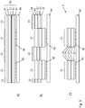
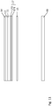
- Fig. 1A shows a transfer film 1 with a base film 10 and a further carrier film 40.
- the base film 10 comprises a carrier film 11, a release layer 12 and a decorative layer 13, which can comprise a protective lacquer layer, a replication lacquer layer, a reflection layer and an adhesive layer 14.
- a reinforcement layer with a layer thickness of approximately 0.1 ⁇ m to 5 ⁇ m, preferably of 1 ⁇ m to 3 ⁇ m can be provided for additional mechanical stabilization in the case of lamination, for example in a plastic card structure.
- a further reinforcement layer with a layer thickness of approximately 0.1 ⁇ m to 10 ⁇ m, preferably approximately 0.5 ⁇ m to 5 ⁇ m may be provided for additional mechanical stabilization in the case of a lamination, for example in a plastic card structure.
- These aforementioned reinforcement layers can also be constructed in multiple layers.
- the carrier film 11 is preferably a PET, PEN or BOPP film with a thickness of 6 ⁇ m to 125 ⁇ m.
- the release layer and the decorative layer are then built up one after the other on the carrier film 11 by applying further layers.
- the release layer 12 is first applied to the carrier film 11.
- the release layer 12 preferably consists of a wax-like material, which is softened in particular by the heat occurring during a hot stamping process and enables the decorative layer to be reliably separated from the carrier film 11.
- the release layer can be constructed in several layers (for example from a layer of wax and then a layer of release lacquer).
- the total thickness of the release layer is preferably between 0.01 ⁇ m to 1.2 ⁇ m.
- the protective lacquer layer is then applied in a layer thickness between 0.5 ⁇ m and 1.5 ⁇ m. It is also possible here for the protective lacquer layer to take over the function of the release layer 12 and accordingly to enable the decorative layer 13 to be separated from the carrier film 11 and also to protect the decorative layer 13 from mechanical influences and environmental influences. It is also possible that the protective lacquer layer 13 is colored or contains micro- and nano-particles.
- the replication lacquer layer consists of a thermoplastic lacquer in which a surface structure is molded by means of heat and pressure through the action of an embossing tool. Furthermore, it is also possible for the replication lacquer layer to be formed by a UV-crosslinkable lacquer and for the surface structure to be molded into the replication lacquer layer by means of UV replication.
- the replication lacquer layer preferably has a layer thickness between 0.5 ⁇ m and 15 ⁇ m.
- the surface structure molded into the replication lacquer layer is preferably a diffractive surface structure, for example a hologram, Kinegram® or some other diffraction-optically active grating structure.
- Such surface structures usually have a spacing of the structural elements in the range from 0.1 ⁇ m to 4 ⁇ m. It is further it is also possible for the surface structure to be a macroscopic surface structure, for example a microlens field or a blaze grating.
- the reflection layer is applied to the replication lacquer layer.
- the reflection layer is preferably a metal layer made of chromium, copper, silver or gold or an alloy of such metals, which is evaporated in a vacuum in a layer thickness of 0.01 ⁇ m to 0.10 ⁇ m.
- Such a dielectric reflection layer consists, for example, of a vapor-deposited layer made of a metal oxide, metal sulfide, titanium dioxide, etc. with a thickness of 10 nm to 150 nm.
- the decorative layer 13 can comprise one or more electrically conductive or semiconductor layers which implement an electrical circuit or an electrical component, for example an RF resonance circuit or an RFID tag.
- This can be a metallic layer, for example, which is either vapor-deposited or printed on and then reinforced by galvanic growth.
- the reflection layer 16 can simultaneously serve as an electrically conductive layer, which can also be galvanically amplified for this purpose.
- the decorative layer 13 can comprise one or more layers made of a magnetic material or an electroluminescent material.
- the adhesive layer 14 which can be constructed in multiple layers and / or on an aqueous or solvent-based basis and / or radiation-curing or combinations thereof, is applied in a total layer thickness of approximately 0.3 ⁇ m to 25 ⁇ m.
- the adhesive layer 14 preferably consists of a thermally activatable adhesive and is applied to the entire surface of the layer 13, for example by means of a doctor blade.
- an adhesive layer 15 is applied, which preferably also consists of a thermally activatable adhesive and is applied over the entire surface.
- the base film 10 and thus also the decorative layer 13 has two first partial areas 21 and a second partial area 22 surrounding the first partial areas 21.
- the first partial areas represent the part of the decorative layer which is to be transferred as a security element to a target substrate, for example a security document.
- the relief structure molded into the replication lacquer layer is preferably selected such that it generates predetermined optically variable information in the first partial regions 21.
- the surface structure molded in the first partial areas 21 thus preferably differs from the surface structure molded in the partial area 22 in the replication lacquer layer.
- the reflection layer is preferably provided in the form of a pattern and partially and provides second predefined information in the first partial regions 21.
- the pattern-like configuration of the reflection layer in the first partial regions 21 thus preferably also differs from that in the second partial region 22.
- the reflective layer is preferably not provided in the second partial region 22.
- the optional further optically active layers of the decorative layer 13 are also preferably formed in register with respect to the partial areas 21 and provide further information in the partial areas 21, so that the molding takes place this layer also differs in the first partial regions 21 from that in the second partial region 22.
- first partial regions 21 are provided which are enclosed by a continuous second partial region 22 which surrounds the first partial regions 21.
- a first adhesive layer 30 is applied to the further carrier film 40.
- the adhesive layer 30 is applied only in the area of the first partial areas 21 and preferably in a grid.
- the adhesive layer 30 is a UV-activatable adhesive.
- the adhesive that can be used for the adhesive layer 30 has the following composition, for example: Dicyclopentyloxyethyl methacrylate 50% to 60% 2-hydroxyethyl methacrylate 8th% trimethylolpropane 40% to 30% (3- (2,3-epoxypropoxy) propyl) trimethoxysilane 1% 1-hydroxy-cyclohexyl-phenyl-ketone (Irgacure 184 (BASF)) 1 to 2%
- composition that can be used for the adhesive layer 30 is, for example: Dicyclopentyloxyethyl methacrylate 50% to 55% 2-hydroxyethyl methacrylate 8th% trimethylolpropane 35% to 30% Phenol, ethoxylated, esters with acrylic acid 5% Dipropyleneglycoldiacrylate 5% (3- (2,3-epoxypropoxy) propyl) trimethoxysilane 1% 1-hydroxycyclohexylphenyl ketone (Irgacure 184 (BASF)) 1 to 2%
- the adhesive layer 30 is applied to the carrier film 40 in a layer thickness of 0.1 ⁇ m to 10 ⁇ m by means of a printing process, by means of casting or by means of a doctor blade.
- the carrier film 40 is a transparent plastic film which preferably consists of PET, PVC, PEN or BOPP film and has a layer thickness of 6 ⁇ m to 250 ⁇ m.
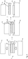
- the production of the transfer film 1 is illustrated step by step. How Figure 2A shows, the base film 10 is first provided without the adhesive layers 14 and 15, which are applied in the following process step. After the adhesive layers 14 and 15 have been dried, the transfer film 40 is connected to the base film via the adhesive layer 30.
- the adhesive layer 30 can be applied to the transfer film 40 or to the adhesive layer 15. It is possible and preferred to apply the adhesive layer 30 only in the region 21.
- the adhesive layer 30 can also be applied over the entire surface and activated only in the region 21.
- a first area of the adhesive layer 30 is activated by exposure.
- the in Figure 2C shown film structure consisting of the carrier film 40, the adhesive layer 30, the carrier film 11, the release layer 12 and the decorative layer 13, exposed in the region 31 with UV light.
- a collimated light source is used, which is spaced on the side of the carrier film 40 facing away from the carrier film 11 and at a distance from the carrier film 40.
- an exposure mask is arranged in the beam path between the light source and the adhesive layer 30, which covers the area 32 and thus enables selective exposure of the area 31.
- the exposure source and the exposure mask are preferably part of a drum imagesetter via which the Foil body is guided.
- the exposure mask is shaped and arranged in such a way that the area 31 largely covers the first partial areas 21 and is positioned within a register tolerance of preferably 0.1 mm to 2.0 mm to the first partial areas 21.
- the adhesive layer 30 is not exposed to UV light and is therefore not activated.
- the UV adhesive is preferably radically UV-curing and therefore has a solids content of 100%. A fraction of monomers can also evaporate during UV curing because heat is also introduced into the layer by the UV radiation if the adhesive is not completely enclosed between two adjacent layers, in particular foils.
- the heat sealable adhesive consists of acrylates and solvents (isopropanol + toluene).
- the solids content is 19% to 20% to ensure the application to the painting machine. It has a non-sticky surface at room temperature (approx. 20 ° C) after drying, especially at room temperature, since neither the melting point nor the glass transition temperature are below 30 ° C and therefore always above the processing (manufacturing) temperature of the film.
- the decorative layer 13, the release layer 12 and the carrier film 11 are severed along the boundary lines defining the first partial regions 21 and separating the first partial regions 21 from the partial region 22.
- These layers are preferably severed by means of a punch which has corresponding recesses in the Introduces layers 30 and 15 to 11 existing film body. It is also possible that the punching depth is selected so that the carrier film 40 is also partially cut. Furthermore, it is also possible that the carrier film 11 is not completely, but only partially severed. On the one hand, this can be done in such a way that regions alternate along the boundary line in which the carrier film 11 is completely cut or not cut or that the carrier film 11 is not cut in its entire thickness, but only, for example, in 80% of its thickness.
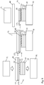
- the multilayer body 1 can be used as a transfer film for applying a security element 23 to a target substrate 70.
- the multilayer body 1 is placed on the target substrate 70 and the adhesive layers 14 and 15 are activated in a first partial area by an appropriately shaped hot stamp 71.
- the adhesive layer 14 By activating the adhesive layer 14, the transfer layer of the multilayer body 1 is connected to the target substrate 70.
- the adhesive layer 15 is activated, which increases the adhesion between the carrier layers 11 and 40, preferably by more than 50%, preferably more than 100%, particularly preferably more than 200%.
- the embossing takes place at a temperature from 80 ° C. to 300 ° C., preferably from 100 ° C. to 240 ° C., particularly preferably from 100 ° C. to 180 ° C. and / or with a Embossing pressure from 10 N / cm 2 to 10000 N / cm 2 , preferably from 100 N / cm 2 to 5000 N / cm 2 and / or with an embossing time from 0.01s to 2s.
- the multilayer body comprising the carrier film 40, the adhesive layer 30 and the carrier film 11 is then pulled off the applied area of the decorative layer 13, so that the security element 23 remains on the target substrate 70, as shown in FIG Fig. 4 is shown.
- Activation of the adhesive layer 15 ensures that no carrier film remains on the security element 23.
- the decorative layer comprises an optional protective lacquer layer 131 with a preferred layer thickness of 0.1 ⁇ m to 20 ⁇ m, particularly preferably from 0.5 ⁇ m to 10 ⁇ m, a replication lacquer layer with a preferred layer thickness of 0.1 ⁇ m to 10 ⁇ m, particularly preferably from 0 .5 ⁇ m to 5 ⁇ m with reflection layer 132, a primer lacquer layer 133 with a preferred layer thickness of 0.1 ⁇ m to 5 ⁇ m, particularly preferably from 1 ⁇ m to 3v, a volume hologram layer 134 with a preferred layer thickness of 5 ⁇ m to 50 ⁇ m, particularly preferred from 10 ⁇ m to 20 ⁇ m and a sealing wax layer 135 with a preferred layer thickness of 0.1 ⁇ m to 5 ⁇ m, particularly preferably from 5 ⁇ m to 15 ⁇ m.
- a volume hologram is written into the volume hologram layer 134, which forms the essential security feature of the resulting security element 32.
- the decorative layer 13 consists of a pressure-imparting layer 136 with a preferred layer thickness of 1 ⁇ m to 30 ⁇ m, particularly preferably from 1 ⁇ m to 3 ⁇ m, to which an individualization feature can be applied by ink jet printing.
- This layer 136 can also be used with all others already described layers of the decorative layer 13 can be combined in order to create an individualized security element 23.
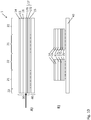
- FIGs 7A and 7B a schematic sectional illustration of a further transfer film 1 is shown.
- a release system 17 is provided on the second carrier film 40.
- the detachment system 17 makes it possible for the first carrier film 11 to remain on the security element 23 or in its layer composite when the security element 23 is applied.
- a self-supporting security element 23 can be produced, which for example can close or cover recesses, in particular window openings, in the target substrate 70.
- the additional mechanical stability that the first carrier film 11 gives to the security element 23 can serve to increase the optical brilliance of the security element 23 when the security element 23 is laminated, for example, in a plastic composite, as is the case, for example, with security documents made of polycarbonate (PC). in the ID card format or other laminates.
- PC polycarbonate
- This additional mechanical stability can also be advantageous when the target substrate 70 is processed further, for example when overprinting with a steel engraving.
- the in Figure 7A The arrow shown shows the position of the separation when the transfer film 1 is applied to a target substrate 70.
- the base film 10 is preferably designed here as a laminating film.
- the total thickness of the stripping system 17 is preferably between 0.01 ⁇ m to 4 ⁇ m.
- the release system 17 preferably has a layer of wax 171.
- the wax-like material is softened by the heat occurring during a hot stamping process and enables the second carrier film 40 to be reliably separated.
- the release system 17 may further comprise a layer of a varnish 172.
- the varnishes 172 are preferably based on acrylates, polyurethanes or cellulose derivatives.
- the lacquer layer 172 preferably has a thickness in the range from 0.1 to 3 ⁇ m, preferably in the range from 0.2 to 1.5 ⁇ m.
- Figure 8 shows a possible production of the transfer film 1.
- the release system 17 in particular consisting of a wax layer 171 which adjoins the second carrier film 40 and a lacquer layer 172, is applied to the second carrier layer 40.
- the base film 10 preferably has the adhesive layer 14, the decorative layer 13 and the first carrier film 11 and the adhesive layer 15.
- the Figure 9 shows the at least area-wise application of the transfer film 1 to a target substrate 70.
- the transfer film 1 is placed on the target substrate 70 and the adhesive layers 14 and 15 are activated in a first partial area 21 by an appropriately shaped hot stamp 71.
- the adhesive layer 14 By activating the adhesive layer 14, the transfer layer of the transfer film 1 is connected to the target substrate 70.
- the adhesive layer 15 is activated, which increases the adhesion between the first carrier layer 11 and the release system 17.
- the wax layer 171 softening during the application of heat also ensures a clean separation between the release system 17 and the second carrier film 40.
- the detachment system 17 remains together with the first carrier film 11 and the decorative layer 13, preferably as a security element 23, after application to the target substrate 70. Since the detachment system 17 forms the outer surface of the security element 23 and can be configured in a wide variety of ways, the security element can thereby be designed can be equipped with additional functions. Examples are better wettability or overprintability with further functional layers or, on the contrary, a hydrophobic function or other functions that repel liquids, or also the production of an optical matting and / or an optical gloss and / or the production of special tactile properties. It is also possible, to supplement additional security prints in the visible wavelength range, UV range, IR range. Individual or all layers of the release layer system can be provided over the entire surface or only in partial surface areas.
- FIGS 10A and 10B a schematic sectional illustration of a further transfer film 1 is shown.
- a release system 17 is provided on the first carrier film 11.
- the detachment system 17 makes it possible for the first carrier film 11 to remain on the security element 23 or in its layer composite when the security element 23 is applied.
- a self-supporting security element 23 can be produced, which can, for example, close or cover recesses, in particular window openings, in the target substrate 70.
- the additional mechanical stability that the first carrier film 11 gives to the security element 23 can serve to increase the optical brilliance of the security element 23 when the security element 23 is laminated, for example, in a plastic composite, as is the case, for example, with security documents made of polycarbonate (PC). in the ID card format or other laminates.
- PC polycarbonate
- This additional mechanical stability can also be advantageous when the target substrate 70 is processed further, for example when overprinting with a steel engraving.
- the in Figure 10A The arrow shown shows the position of the separation when the transfer film is applied to a target substrate 70.
- the base film 10 is preferably designed here as a laminating film.
- the total thickness of the stripping system 17 is preferably between 0.01 ⁇ m to 4 ⁇ m.
- the release system 17 preferably has a layer of wax 171.
- the wax-like material is softened by the heat occurring during a hot stamping process and enables the second carrier film 40 to be reliably separated.
- the release system 17 may further comprise a layer of a varnish 172.
- the paint 172 is preferably based on acrylates, polyurethanes or cellulose derivatives.
- the lacquer layer 172 preferably has a thickness in the range from 0.1 to 3 ⁇ m, preferably in the range from 0.2 to 1.5 ⁇ m.
- Figure 11 shows a possible production of the transfer film 1.
- the release system 17 is applied to the side of the first carrier film 11 of the base film 10 facing away from the decorative layer 13.
- the release system 17 can have a wax layer 171 and a lacquer layer 172.
- the adhesive layer 15 is then preferably applied to the outer, free side of the release system 17.
- the adhesive layer 15 is preferably in contact with the adhesive layer 30.
- This embodiment variant can also make it possible for the base film 10 to remain on the security element 23 or in its layer composite when the security element 23 is applied. As a result, a self-supporting security element 23 can be produced, which for example can close or cover recesses, in particular window openings, in the target substrate.
- auxiliary layers (not shown) to be applied to the side of the first carrier film 11 of the base film 10 facing away from the decorative layer 13, which are then arranged between the first carrier film 11 and the release system 17, before the release system 17 is applied .
- the Figure 12 shows the at least partial application of the transfer film 1 to a target substrate 70.
- the transfer film 1 is placed on the target substrate 70.
- the adhesive layer 14 By activating the adhesive layer 14, the transfer layer of the transfer film 1 is connected to the target substrate 70.
- the wax layer softened during application by the action of heat 171 ensures a clean separation between the release system 17 and the first carrier film 11.
- the detachment system 17 is detached from the security element 23 after application to the target substrate 70. If auxiliary layers are arranged between the detachment system 17 and the first carrier film 11, the auxiliary layers form the outer, free surface of the security element 23. If these auxiliary layers are dispensed with, the carrier film 11 forms the outer, free surface of the security element 23 and thus allows a particularly brilliant optical effect of the security element 23.
Landscapes
- Engineering & Computer Science (AREA)
- Manufacturing & Machinery (AREA)
- General Health & Medical Sciences (AREA)
- Chemical & Material Sciences (AREA)
- Chemical Kinetics & Catalysis (AREA)
- General Chemical & Material Sciences (AREA)
- Health & Medical Sciences (AREA)
- Toxicology (AREA)
- Decoration By Transfer Pictures (AREA)
- Laminated Bodies (AREA)
- Impression-Transfer Materials And Handling Thereof (AREA)
- Credit Cards Or The Like (AREA)
- Holo Graphy (AREA)
Description
Die Erfindung betrifft ein Verfahren zur Herstellung eines Sicherheitselements sowie eine Transferfolie, insbesondere eine Heißprägefolie, zum Transfer eines oder mehrerer Mehrschichtkörper auf ein Zielsubstrat.The invention relates to a method for producing a security element and a transfer film, in particular a hot stamping film, for transferring one or more multilayer bodies to a target substrate.
Zur Applizierung eines Sicherheitselements auf Sicherheitsdokumente, beispielsweise Reisepässe, Kreditkarten oder Banknoten, werden u.a. Transferfolien, insbesondere Heißprägefolien eingesetzt. Dabei wird ein Sicherheitselement auf ein Substrat gebracht, das von der Dekorlage einer Heißprägefolie gebildet wird. Das Sicherheitselement umfasst dabei beispielsweise eine insbesondere transparente Lackschicht, in die eine Struktur, insbesondere zur Erzeugung eines optisch variablen Effektes, insbesondere eine beugungsoptisch wirksame Struktur abgeformt ist. Die transparente Lackschicht kann beispielsweise weiter mit einer die Reflexion erhöhenden Schicht versehen sein, bei der es sich um eine Metallschicht oder eine dielektrische Schicht handelt. Weiter weist das Sicherheitselement eine Klebstoffschicht auf, mittels der das Sicherheitselement auf das Substrat festgelegt ist. Hierzu wird die Heißprägefolie auf das Substrat aufgelegt und mittels eines Prägestempels unter Einwirkung von Wärme und Druck in dem Bereich auf die Decklage gepresst, in dem die Dekorlage der Heißprägefolie auf das Substrat zu transferieren ist. Beim Abziehen des Trägerfilms der Heißprägefolie haftet dieser Teilbereich der Dekorlage weiter am Substrat fest, die übrigen Teilbereiche der Dekorlage werden zusammen mit dem Trägerfilm abgezogen.Transfer foils, in particular hot stamping foils, are used, among other things, to apply a security element to security documents, for example passports, credit cards or banknotes. A security element is placed on a substrate, which is formed by the decorative layer of a hot stamping foil. The security element in this case comprises, for example, an in particular transparent lacquer layer, into which a structure, in particular for producing an optically variable effect, in particular a structure with an optical diffraction effect, is molded. The transparent lacquer layer can, for example, also be provided with a reflection-increasing layer, which is a metal layer or a dielectric layer. Furthermore, the security element has an adhesive layer, by means of which the security element is fixed on the substrate. For this purpose, the hot stamping film is placed on the substrate and pressed by means of a stamp under the influence of heat and pressure in the area in which the decorative layer of the hot stamping film is to be transferred to the substrate. When the carrier film of the hot stamping foil is peeled off, it adheres Part of the decorative layer is still firmly attached to the substrate, the other partial areas of the decorative layer are pulled off together with the carrier film.
Bei einer derartigen Übertragung der Dekorlage einer Heißprägefolie von einem Trägerfilm auf ein Substrat wird die Dekorlage der Prägefolie entlang der Grenzlinie, die den zu übertragenden Teilbereich der Dekorlage definiert, zerrissen. Diese Grenzlinie kann beispielsweise durch die umlaufenden Außenkanten eines Prägestempels als Prägekontur definiert sein. Dies kann insbesondere bei der Verwendung von Transferfolien mit dickeren Schichten und Schichten mit speziellen Eigenschaften, beispielsweise Schichten mit besonders hoher Zähigkeit und/oder Sprödigkeit, zu Randausfransungen (als Positiv- und/oder Negativform) führen.In such a transfer of the decorative layer of a hot stamping film from a carrier film to a substrate, the decorative layer of the stamping film is torn along the boundary line that defines the portion of the decorative layer to be transferred. This boundary line can be defined, for example, by the peripheral outer edges of an embossing stamp as an embossing contour. This can lead to fraying of the edge (as a positive and / or negative form), in particular when using transfer films with thicker layers and layers with special properties, for example layers with particularly high toughness and / or brittleness.
Um diese Probleme zu umgehen, ist es bekannt, eine weitere Trägerlage als Hilfsträger im Bereich der zu übertragenden Teilbereiche mit der Trägerlage der Heißprägefolie zu verkleben und die Heißprägefolie entlang des Umrisses der zu übertragenden Teilbereiche (sogenannte Patches) zumindest teilweise zu durchstanzen. Die nicht benötigten Teilbereiche können dann abgelöst werden. Die verbleibenden Teilbereiche können anschließend randscharf abgeprägt werden.In order to avoid these problems, it is known to glue a further carrier layer as an auxiliary carrier in the region of the partial regions to be transferred to the carrier layer of the hot stamping foil and to at least partially punch through the hot stamping foil along the outline of the partial regions to be transferred (so-called patches). The sub-areas that are not required can then be replaced. The remaining sections can then be embossed to the edge.
Bei dieser Technologie besteht das Problem, dass der dort verwendete partiell aufgebrachte UV-Klebstoff in einem etwas größeren Bereich aufgebracht wird als der gestanzte Patch groß ist, um Registerschwankungen beim UV-Klebstoffdruck aufzufangen, damit auf jeden Fall der komplette Patch mit dem UV-Klebstoff bedeckt ist. Daher existiert ein Klebstoff-Rand rund um den Patch im ausgestanzten Zustand.The problem with this technology is that the partially applied UV adhesive used there is applied in a somewhat larger area than the punched patch is large in order to compensate for register fluctuations in UV adhesive printing, and therefore definitely the complete patch with the UV adhesive is covered. Therefore, there is an adhesive edge around the patch when punched out.
Unter Register oder Passer bzw. Registergenauigkeit oder Passergenauigkeit ist eine Lagegenauigkeit zweier oder mehr Elemente und/oder Schichten, hier insbesondere des Substrats und der Prägefolie und/oder des Dekorabschnitts zueinander zu verstehen. Dabei soll sich die Registergenauigkeit innerhalb einer vorgegebenen Toleranz bewegen und dabei möglichst gering sein. Gleichzeitig ist die Registergenauigkeit von mehreren Elementen und/oder Schichten zueinander ein wichtiges Merkmal, um die Prozesssicherheit zu erhöhen. Die lagegenaue Positionierung kann dabei insbesondere mittels sensorisch, vorzugsweise optisch detektierbarer Passermarken oder Registermarken erfolgen. Diese Passermarken oder Registermarken können dabei entweder spezielle separate Elemente oder Bereiche oder Schichten darstellen oder selbst Teil der zu positionierenden Elemente oder Bereiche oder Schichten sein.Register or register or register accuracy or register accuracy is understood to mean the positional accuracy of two or more elements and / or layers, here in particular the substrate and the embossing film and / or the decorative section. The register accuracy should be within a predetermined tolerance and should be as low as possible. At the same time, the register accuracy of several elements and / or layers to one another is one important feature to increase process security. The positionally accurate positioning can take place in particular by means of sensor marks, preferably optically detectable registration marks or register marks. These registration marks or register marks can either represent special separate elements or areas or layers or can themselves be part of the elements or areas or layers to be positioned.
Dieser UV-Klebstoff erfüllt dabei eine Doppelfunktion. Während der Applikation der Folie soll der UV-Klebstoff den Hilfsträger und den Träger fest zusammenhalten, um das Abziehen des Hilfsträgers und des Trägers gleichzeitig von der applizierten Transferlage zu gewährleisten. Während der Verarbeitung/Herstellung der Folie soll der UV-Klebstoff der zu übertragende Teilbereich an Ort und Stelle fixieren (zum Beispiel bei Umrollvorgängen) aber auch das Abziehen der nicht benötigten Teilbereiche erlauben, d.h. seine Haftkraft, insbesondere am Klebstoffrand soll doch nicht zu groß sein.This UV adhesive fulfills a double function. During the application of the film, the UV adhesive should hold the auxiliary carrier and the carrier firmly together in order to ensure that the auxiliary carrier and the carrier are simultaneously pulled off the applied transfer layer. During processing / production of the film, the UV adhesive should fix the partial area to be transferred in place (for example during rewinding processes) but also allow the unneeded partial areas to be peeled off, i.e. its adhesive force, especially on the edge of the adhesive, should not be too great.
Der UV-Klebstoff wird daher nur teilweise durchgehärtet, d.h. obwohl dieser Klebstoff UV-gehärtet ist, weist er eine Restklebrigkeit auf und diese tritt bei der weiteren Applikation nachfolgend störend in Erscheinung, insbesondere im Bereich des zuvor erwähnten überstehenden Klebstoffrandes. Die Restklebrigkeit kann auch erst durch einen Wärmeeintrag beim Heißprägen oder bei anderen Produktionsschritten gebildet werden, beispielsweise bei vorher unzureichender Härtung oder generell zu geringer Temperaturbeständigkeit des Klebstoffs Die erwähnte Restklebrigkeit kann jedoch auch bei UV-Klebstoffen auftreten, die weitgehend vollständig ausgehärtet wurden.The UV adhesive is therefore only partially hardened, i.e. although this adhesive is UV-cured, it has a residual tack and this subsequently becomes a nuisance during further application, in particular in the area of the above-mentioned protruding adhesive edge. The residual stickiness can also only be formed by heat input during hot stamping or in other production steps, for example if the adhesive has previously been insufficiently hardened or the temperature resistance of the adhesive is generally too low. However, the mentioned residual tack can also occur with UV adhesives which have largely been fully cured.
Zudem reicht die Haftung des UV-Klebstoffs zwischen Hilfsträger und Träger während der Applikation nicht immer aus, um die Transferlagen allein zu übertragen, und es wird dann der gesamte Patch inklusive der Trägerlage übertragen, die sich in ungewünschter Weise von dem Hilfsträger ablöst.In addition, the adhesion of the UV adhesive between the auxiliary carrier and carrier during application is not always sufficient to transfer the transfer layers alone, and the entire patch including the carrier layer is then transferred, which detaches from the auxiliary carrier in an undesired manner.
Aus der internationalen Patentanmeldung
Der Erfindung liegt nun die Aufgabe zugrunde, ein verbessertes Verfahren zur Herstellung eines Dekorelements bzw. eines Sicherheitselements sowie eine verbesserte Transferfolie anzugeben.The invention is based on the object of specifying an improved method for producing a decorative element or a security element and an improved transfer film.
Diese Aufgabe wird durch ein Verfahren mit den Merkmalen von Patentanspruch 1 und eine Transferfolie mit den Merkmalen von Patentanspruch 46 gelöst.This object is achieved by a method with the features of
Ein solches Verfahren zur Herstellung eines Sicherheitselements zeichnet sich dadurch aus, dass bei dem Verfahren eine Grundfolie bereit gestellt wird, die eine erste Trägerfolie und eine ein- oder mehrschichtige Dekorlage aufweist,
- wobei auf eine zweite Trägerfolie eine erste Klebstoffschicht aufgebracht wird und auf die von der Dekorlage abgewandte Oberfläche der ersten Trägerfolie eine zweite Klebstoffschicht aufgebracht wird, oder wobei die zweite Klebstoffschicht auf die von der Dekorlage abgewandte Oberfläche der ersten Trägerfolie aufgebracht wird und die erste Klebstoffschicht auf die zweite Klebstoffschicht aufgebracht wird,
- und wobei die zweite Trägerfolie auf die erste Trägerfolie aufgebracht wird derart, dass die erste Klebstoffschicht und die zweite Klebstoffschicht zwischen der ersten Trägerfolie und der zweiten Trägerfolie angeordnet sind,
- und wobei die erste Klebstoffschicht in einem ersten Bereich, der mindestens einen ersten Teilbereich der Grundfolie zumindest teilweise überdeckt, aktiviert wird und in einem an diesen Bereich angrenzenden zweiten Bereich die erste Klebstoffschicht jedoch nicht aktiviert, nicht vorgesehen, lediglich teilweise vorgesehen oder deaktiviert wird,
- wobei die erste Trägerfolie entlang der den mindestens einen ersten Teilbereich definierenden und den mindestens einen ersten Teilbereich von einem zweiten Teilbereich der Grundfolie trennenden Grenzlinie mindestens teilweise durchtrennt wird, und
- wobei ein den zweiten Teilbereich umfassender zweiter Teil der Grundfolie von der zweiten Trägerfolie abgezogen wird, wobei in dem mindestens einen ersten Teilbereich die Grundfolie aufgrund der aktivierten ersten Klebstoffschicht an der zweiten Trägerfolie haftet und ein den mindestens einen ersten Teilbereich
- wherein a first adhesive layer is applied to a second carrier film and a second adhesive layer is applied to the surface of the first carrier film facing away from the decorative layer, or wherein the second adhesive layer is applied to the surface of the first carrier film facing away from the decorative layer and the first adhesive layer to the second layer of adhesive is applied,
- and wherein the second carrier film is applied to the first carrier film such that the first adhesive layer and the second adhesive layer are arranged between the first carrier film and the second carrier film,
- and wherein the first adhesive layer is activated in a first area that at least partially covers at least a first partial area of the base film and the first adhesive layer is not activated, not provided, only partially provided or deactivated in a second area adjacent to this area,
- wherein the first carrier film is at least partially severed along the boundary line defining the at least one first partial area and separating the at least one first partial area from a second partial area of the base film, and
- wherein a second part of the base film comprising the second partial area is pulled off the second carrier film, the base film adhering to the second carrier film in the at least one first partial area due to the activated first adhesive layer, and the at least one first partial area
umfassender erster Teil der Grundfolie auf der zweiten Trägerfolie verbleibt.comprehensive first part of the base film remains on the second carrier film.
Ein Klebstoff kann ein Polymer, beispielsweise ein Lack als flüssiger, pastöser oder auch pulverförmiger Beschichtungsstoff sein, der dünn auf Oberflächen aufgetragen wird und durch chemische und/oder physikalische Vorgänge einen insbesondere durchgehenden Film bildet.An adhesive can be a polymer, for example a lacquer as a liquid, pasty or also powdery coating material, which is applied thinly to surfaces and forms a continuous film in particular through chemical and / or physical processes.
Man erhält so eine Transferfolie, insbesondere Heißprägefolie, zum Transfer eines oder mehrerer Mehrschichtkörper auf ein Zielsubstrat, wobei die Transferfolie eine Grundfolie aufweist, welche eine erste Trägerfolie und eine ein- oder mehrschichtige Dekorlage aufweist, wobei
- die Transferfolie weiter eine zweite Trägerfolie mit einer ersten Klebstoffschicht und eine auf die von der Dekorlage abgewandte Oberfläche der ersten Trägerfolie aufgebrachte zweite Klebstoffschicht aufweist, wobei die erste Klebstoffschicht und die zweite Klebstoffschicht zwischen der ersten Trägerfolie und der zweiten Trägerfolie angeordnet sind, und wobei
- die erste Klebstoffschicht in einem mindestens einen ersten Teilbereich der Grundfolie zumindest teilweise überdeckenden ersten Bereich aktiviert ist, so dass die Grundfolie in dem mindestens einen ersten Teilbereich an der zweiten Trägerfolie haftet, und in einem an dem mindestens einen ersten Teilbereich angrenzenden zweiten Teilbereich jedoch nicht aktiviert, nicht vorgesehen, lediglich teilweise vorgesehen oder deaktiviert ist, und wobei
- die erste Trägerfolie entlang der den mindestens einen ersten Teilbereich definierenden und den mindestens einen ersten Teilbereich von einem zweiten Teilbereich der Grundfolie trennenden Grenzlinie durchtrennt und ein den zweiten Teilbereich umfassender Teil der Grundfolie von der zweiten Trägerfolie abgezogen ist.
- the transfer film further has a second carrier film with a first adhesive layer and a second adhesive layer applied to the surface of the first carrier film facing away from the decorative layer, the first adhesive layer and the second adhesive layer being arranged between the first carrier film and the second carrier film, and wherein
- the first adhesive layer is activated in an at least partially covering first area of at least a first partial area of the base film, so that the base film adheres to the second carrier film in the at least one first partial area, but is not activated in a second partial area adjacent to the at least one first partial area , not provided, is only partially provided or deactivated, and wherein
- the first carrier film is cut along the boundary line defining the at least one first partial area and separating the at least one first partial area from a second partial area of the base film, and a part of the base film comprising the second partial area is pulled off the second carrier film.
Hierdurch ist es möglich, ein Sicherheitselement bereit zu stellen, welches mittels eines üblichen Transferverfahrens auf ein Sicherheitsdokument, beispielsweise eine Banknote oder ein ID-Dokument, transferiert werden kann und welches ein durch das Brechen der Dekorlage im Randbereich des transferierten Mehrschichtkörpers entstehendes "Ausfransen" vermeidet. Weiter ist es möglich, dass die Haft- und Struktureigenschaften der Dekorlage im Wesentlichen unabhängig von den Anforderungen des Transfer-Prozesses gewählt werden können und so beispielsweise die optischen Eigenschaften, die Beständigkeit gegenüber Umwelteinflüssen sowie die Sicherheit gegenüber Nachahmung und Manipulation des Sicherheitselements weiter verbessert werden können. Insbesondere können so besonders spröde oder dicke oder zähe Schichten in der Dekorlage transferiert werden. Weiter zeichnet sich das erfindungsgemäße Verfahren dadurch aus, dass die Passergenauigkeit, mit der Sicherheitselemente auf ein Zielsubstrat transferiert werden können, weiter verbessert wird.This makes it possible to provide a security element which can be transferred to a security document, for example a bank note or an ID document, by means of a conventional transfer method and which can be transferred by means of the Breaking of the decorative layer in the edge area of the transferred multilayer body avoids "fraying". It is also possible that the adhesive and structural properties of the decorative layer can be selected essentially independently of the requirements of the transfer process, and thus, for example, the optical properties, the resistance to environmental influences and the security against imitation and manipulation of the security element can be further improved , In particular, particularly brittle or thick or tough layers can be transferred in the decorative layer. Furthermore, the method according to the invention is characterized in that the registration accuracy with which security elements can be transferred to a target substrate is further improved.
Im Sinne der Erfindung ist unter Transferfolie ganz allgemeine eine Folie zu verstehen, die eine Trägerlage bzw. Trägerfolie und eine Transferlage aufweist, wobei die Transferlage, die insbesondere wenigstens eine Dekorlage aufweist, von der Trägerlage ablösbar ist. Die Ablösung erfolgt insbesondere in einer Prägevorrichtung, wobei wenigstens ein Teil der Transferfolie auf ein zu dekorierendes Substrat übertragen wird und im Anschluss die Trägerlage von der applizierten Transferlage abgezogen wird.For the purposes of the invention, transfer film is to be understood quite generally as a film which has a carrier layer or carrier film and a transfer layer, the transfer layer, which in particular has at least one decorative layer, being detachable from the carrier layer. The detachment takes place, in particular, in an embossing device, at least part of the transfer film being transferred to a substrate to be decorated and the carrier layer then being pulled off the applied transfer layer.
Die Grundfolie kann sowohl als Transferfolie wie auch als Laminierfolie ausgebildet sein. Ist die Grundfolie als Transferfolie ausgebildet, dann wird insbesondere die Dekorlage der Grundfolie auf ein Substrat übertragen und im Anschluss wird die erste Trägerfolie davon abgezogen und verbleibt bevorzugt auf der zweiten Trägerfolie. Hierbei ist besonders bevorzugt eine Ablöseschicht zwischen Dekorlage und erster Trägerfolie angeordnet.The base film can be designed both as a transfer film and as a laminating film. If the base film is designed as a transfer film, then in particular the decorative layer of the base film is transferred to a substrate and then the first carrier film is pulled off it and preferably remains on the second carrier film. In this case, a release layer is particularly preferably arranged between the decorative layer and the first carrier film.
Ist die Grundfolie als Laminierfolie ausgebildet, dann werden insbesondere die Dekorlage und die erste Trägerfolie der Grundfolie auf ein Substrat übertragen und im Anschluss wird die zweite Trägerfolie davon abgezogen. Hierbei ist besonders bevorzugt ein Ablösesystem zwischen der ersten und der zweiten Trägerfolie angeordnet.If the base film is in the form of a laminating film, then in particular the decorative layer and the first carrier film of the base film are transferred to a substrate and the second carrier film is subsequently removed therefrom. Here is special preferably a detachment system is arranged between the first and the second carrier film.
Zudem können unterschiedliche Formen der Transferfolie mit einer gleich bleibenden Stempelform übertragen werden. Es ist auch möglich, mehrere, benachbarte, isolierte Patches mittels eines einzigen Stempels zu übertragen. Die äußere Form des Patches muss nicht mit der äußeren Form des Heißprägestempels übereinstimmen. Vorzugsweise wird hierbei der Heißprägestempel größer als der zu transferierende Teil der Grundfolie gewählt. Beispielsweise wird ein Patch in Sternform mit einem runden, den Stern mehr als vollständig überdeckenden, größeren Stempel übertragen. Neben einem Heißprägestempel, mit dem eine Heißprägung mittels Prägedruck und Wärme durchgeführt wird, kann auch eine Ultraschallprägestempel mit entsprechend gestaltetem Gegendrucklager Anwendung finden, mit dem eine Heißprägung mittels Prägedruck und Ultraschall als alternative Energieform durchgeführt wird. Ebenfalls möglich ist die Verwendung eines Rollenlaminators, insbesondere eines semirotativen Laminators und/oder Mehrrollenlaminators (beispielsweise sind für Banknotenanwendungen mehrere Laminationsrollen in Reihe hintereinander angeordnet). Weiterhin ist es möglich, die erste Trägerfolie mit Hilfe einer Umlenkwalze nahe an die mit UV-Klebstoff bedruckte zweite Trägerfolie heranzuführen, ohne beide Trägerfolien aneinanderzupressen. Zusätzliche, nachfolgende Umlenkwalzen sorgen dann für den nötigen Kontakt beider Trägerfolien vor der Aushärtung mit UV-Licht.In addition, different shapes of the transfer film can be transferred with a constant stamp shape. It is also possible to transfer several, adjacent, isolated patches using a single stamp. The outer shape of the patch does not have to match the outer shape of the hot stamp. The hot stamp is preferably chosen to be larger than the part of the base film to be transferred. For example, a star-shaped patch is transferred with a round, larger stamp that more than completely covers the star. In addition to a hot stamp, with which hot stamping is carried out using embossing pressure and heat, an ultrasonic stamp with an appropriately designed counter-pressure bearing can also be used, with which hot stamping using stamping pressure and ultrasound is carried out as an alternative form of energy. It is also possible to use a roll laminator, in particular a semi-rotary laminator and / or multi-roll laminator (for example, a plurality of lamination rolls are arranged in series for banknote applications). Furthermore, it is possible to bring the first carrier film close to the second carrier film printed with UV adhesive with the aid of a deflecting roller, without pressing the two carrier films together. Additional, subsequent deflection rollers then ensure the necessary contact between the two carrier films before curing with UV light.
Es ist dabei auch möglich, dass der zweite Teilbereich nicht zusammenhängend ist oder auch Unterbereiche aufweist, in denen der gesamte Folienverbund entfernt wird. Beispielsweise kann in einer Ausführungsform jeder Patch zumindest einen umschlossenen Freiraum aufweisen, beispielsweise ein Loch in der Mitte. Das Loch (generell sind alle Formen möglich) dieser Form wird beispielsweise ebenso während des Stanzvorgangs erzeugt. Dabei besitzt das Stanzblech beispielsweise zwei Stanzhöhen; eine, um nur die Dekorlage für die Freistellung von ersten Bereiche und den ggf. vorhandenen beizubehaltenden Markenbereich zu durchtrennen und eine weitere, höhere um den gesamten Folienverbund zu durchtrennen und damit ein Loch zu erzeugen. Auch Lasern mit verschiedenen Einstellungen für Kiss-Cut und Durchstanzen ist prinzipiell möglich. Die dabei entstehenden Folienbruchstücke werden meist aus dem Folienverbund herausgedrückt oder ausgeblasen. In diesem Teilbereich wird also der gesamte Folienverbund entfernt.It is also possible that the second sub-area is not connected or has sub-areas in which the entire film composite is removed. For example, in one embodiment, each patch can have at least one enclosed free space, for example a hole in the middle. The hole (generally all shapes are possible) of this shape is also created during the punching process, for example. The punch plate has, for example, two punch heights; one in order to cut only the decorative layer for the exemption of the first areas and the possibly existing brand area to be retained and one further, higher ones to cut through the entire film composite and thus create a hole. Lasers with different settings for kiss-cut and punching are also possible in principle. The resulting film fragments are usually pressed out or blown out of the film composite. The entire film composite is therefore removed in this partial area.
Die Vorteile solcher Löcher oder Durchbrechungen liegen in einer Verbesserung der Zwischenschichthaftung, wenn der zu übertragende Teilbereich, insbesondere in der späteren Anwendung des Sicherheitselements, zwischen zwei Deckschichten liegt. Ferner kann ein solches Loch als Ersatz und/oder Ergänzung eines optisch transparenten Teilbereichs in dem Motiv dienen. Durch diese Löcher oder Durchbrechungen wird die Filigranität des zu übertragenden Teilbereichs erhöht und damit auch seine Fälschungssicherheit verbessert. Mögliche Motive für die geometrische Gestaltung der Löcher bzw. Durchbrechungen sind alphanumerische Zeichen wie zum Beispiel A, B, D, O, R, 8, 9 6, 0.The advantages of such holes or perforations lie in an improvement in the interlayer adhesion if the sub-area to be transferred, in particular in the later application of the security element, lies between two cover layers. Furthermore, such a hole can serve as a replacement and / or supplement for an optically transparent partial area in the motif. These holes or perforations increase the filigree nature of the sub-area to be transferred and thus also improve its security against forgery. Possible motifs for the geometric design of the holes or perforations are alphanumeric characters such as A, B, D, O, R, 8, 9 6, 0.
Durch die zweite Klebstoffschicht können dabei die eingangs genannten Nachteile der einfachen Verklebung mit einem UV-Klebstoff überwunden werden. Insbesondere können dabei Klebstoffe mit unterschiedlichen Haft- und/oder Aktivierungseigenschaften verwendet werden. Die erste Klebstoffschicht dient dabei lediglich zum leichten Verbinden der beiden Trägerlagen während der Verarbeitung. Die zweite Klebstoffschicht wird bevorzugt erst beim Prägen thermisch aktiviert und erhöht dann die Haftung zwischen den Trägerlagen, so dass diese nach dem Prägen gemeinsam von dem übertragenen Teil der Dekorlage abgelöst werden können. Dies ermöglicht es insbesondere auch, die erste Klebstoffschicht so aufzubringen, dass sie sich nicht über den zu übertragenden Teilbereich hinaus erstreckt, so dass sich später die oben genannten Probleme durch Restklebrigkeit nicht ergeben. Bevorzugt ist die erste Klebstoffschicht also kleiner als der zu übertragende Teilbereich. Prinzipiell fixiert die erste Klebstoffschicht den zu übertragenden Teilbereich an Ort und Stelle, wobei dies auch mit einem vergleichsweise kleinen Klebstoffpunkt erfolgen kann. Dieser kann auch sehr viel kleiner als der zu übertragende Teilbereich sein, sodass die relative Lage zwischen zu übertragendem Teilbereich und der ersten Klebstoffschicht nicht kritisch ist.With the second adhesive layer, the disadvantages mentioned at the outset of simple gluing with a UV adhesive can be overcome. In particular, adhesives with different adhesive and / or activation properties can be used. The first adhesive layer is used only for easy connection of the two carrier layers during processing. The second adhesive layer is preferably only thermally activated during embossing and then increases the adhesion between the carrier layers, so that after the embossing they can be detached together from the transferred part of the decorative layer. In particular, this also makes it possible to apply the first adhesive layer in such a way that it does not extend beyond the portion to be transferred, so that the above-mentioned problems due to residual tack do not arise later. The first adhesive layer is therefore preferably smaller than the partial area to be transferred. In principle, the first adhesive layer fixes the partial area to be transferred in place, although this can also be done with a comparatively small adhesive point. This can also be much smaller than the partial area to be transferred be so that the relative position between the portion to be transferred and the first adhesive layer is not critical.
Die zweite Trägerfolie kann sowohl einlagig als auch mehrlagig sein. Die Lagen können aus unterschiedlichen oder gleichen Materialien bestehen, beispielsweise aus Papier und/oder Gewebe und/oder Teslin® und/oder gleichen oder unterschiedlichen Kunststoffschichten. Sie können miteinander verklebt sein oder zum Beispiel durch Koextrusion oder durch Mehrfachbeschichtungen hergestellt sein.The second carrier film can be either single-layer or multi-layer. The layers can consist of different or the same materials, for example of paper and / or fabric and / or Teslin® and / or the same or different plastic layers. They can be glued to one another or produced, for example, by coextrusion or by multiple coatings.
Bevorzugt werden also für die erste und zweite Klebstoffschicht unterschiedliche, insbesondere unterschiedlich aktivierbare Klebstoffe verwendet. Insbesondere ist es vorteilhaft, für die erste Klebstoffschicht einen strahlungsaktivierbaren Klebstoff und für die zweite Klebstoffschicht einen thermisch aktivierbaren Klebstoff zu verwenden. Ein thermisch aktivierbarer Klebstoff kann sowohl reaktiv als auch nicht reaktiv sein. Zudem sind mehrschichtige Aufbauten möglich. Neben strahlungsaktivierbaren Klebstoffen sind auch andere reaktive Arten von Klebstoffen, wie zum Beispiel Ein- und Zwei-Komponentensysteme (Epoxysysteme und/oder beispielsweise mit Isocyanaten als Initiator für eine Polymerisation bzw. Vernetzung) möglich.Different, in particular differently activatable, adhesives are therefore preferably used for the first and second adhesive layers. In particular, it is advantageous to use a radiation-activatable adhesive for the first adhesive layer and a thermally activatable adhesive for the second adhesive layer. A thermally activatable adhesive can be both reactive and non-reactive. Multi-layer structures are also possible. In addition to radiation-activatable adhesives, other reactive types of adhesives are also possible, such as, for example, one- and two-component systems (epoxy systems and / or, for example, with isocyanates as initiators for polymerization or crosslinking).
Hierbei ist es vorteilhaft, wenn die zweite Klebstoffschicht beim Heißprägen des ersten Teils der Grundfolie auf ein Substrat aktiviert wird. Vor dem Heißprägen weist die zweite Klebstoffschicht also bevorzugt keine Klebrigkeit auf. Beim Heißprägen und der Aktivierung erhöht sich dann die Zwischenschichthaftung zwischen den Trägerlagen, bevorzugt um mehr als 50%, bevorzugt mehr als 100%, besonders bevorzugt mehr als 200%.It is advantageous here if the second adhesive layer is activated when the first part of the base film is hot stamped onto a substrate. Before hot stamping, the second adhesive layer therefore preferably has no stickiness. During hot stamping and activation, the interlayer adhesion between the carrier layers then increases, preferably by more than 50%, preferably more than 100%, particularly preferably more than 200%.
Dabei ist es bevorzugt, wenn das Heißprägen bei einer Temperatur von 80°C bis 300°C, bevorzugt von 100°C bis 240°C, besonders bev orzugt von 100°C bis 180°C und/oder mit einem Prägedruck von 10 N/cm2 bis 10000 N/cm2, bevorzugt von 100 N/cm2 bis 5000 N/cm2 und/oder mit einer Prägezeit von 0,01s bis 2s, bevorzugt von 0,01s bis 1s, erfolgt.It is preferred if the hot stamping at a temperature of 80 ° C to 300 ° C, preferably from 100 ° C to 240 ° C, particularly preferably from 100 ° C to 180 ° C and / or with an embossing pressure of 10 N. / cm 2 to 10000 N / cm 2 , preferably from 100 N / cm 2 to 5000 N / cm 2 and / or with an embossing time of 0.01s to 2s, preferably of 0.01s to 1s.
Weiter ist es vorteilhaft, wenn die zweite Klebstoffschicht vor dem Aufbringen der zweiten Trägerfolie auf die Grundfolie getrocknet wird. Hierdurch wird sichergestellt, dass die zweite Klebstoffschicht vor dem Heißprägen keine Klebrigkeit aufweist. Es können auch variierende Flächenbelegungen der zweiten Klebstoffschicht (zum Beispiel im ersten Teilbereich unterschiedliche Flächenbelegungen im Innen- oder Außenbereich) zum Einsatz kommen. Ferner ist es vorteilhaft, wenn die zweite Klebstoffschicht in einem Raster, insbesondere einem Linienraster oder Punktraster mit einer Rasterdichte von 40 bis 80 Linien pro cm aufgebracht wird.
Besonders bevorzugt ist es, wenn die zweite Klebstoffschicht aus einem thermoplastischen Klebstoff mit einer Glasübergangstemperatur von 50°C bis 150°C, bevorzugt von 100°C bis 120°C gebildet wird. Die zw eite Klebstoffschicht kann mehrschichtig aufgebaut sein.It is also advantageous if the second adhesive layer is dried before the second carrier film is applied to the base film. This ensures that the second adhesive layer has no stickiness before hot stamping. Varying surface assignments of the second adhesive layer (for example, different surface assignments in the inner or outer region in the first partial region) can also be used. It is also advantageous if the second adhesive layer is applied in a grid, in particular a line grid or dot grid with a grid density of 40 to 80 lines per cm.
It is particularly preferred if the second adhesive layer is formed from a thermoplastic adhesive with a glass transition temperature from 50 ° C. to 150 ° C., preferably from 100 ° C. to 120 ° C. The second adhesive layer can be constructed in several layers.
Es ist zweckmäßig, wenn die zweite Klebstoffschicht mit einem Flächengewicht von 0,1 g/m2 bis 10 g/m2, bevorzugt von 2 g/m2 bis 5 g/m2 aufgetragen wird.It is expedient if the second adhesive layer is applied with a basis weight of 0.1 g / m 2 to 10 g / m 2 , preferably 2 g / m 2 to 5 g / m 2 .
Ferner ist es vorteilhaft, wenn die erste Klebstoffschicht in einem Raster, insbesondere einem Linienraster oder Punktraster mit einer Rasterdichte von 40 bis 80 Linien pro cm aufgebracht wird. Es können auch variierende Flächenbelegungen der ersten Klebstoffschicht (zum Beispiel im ersten Teilbereich unterschiedliche Flächenbelegungen im Innen- oder Außenbereich) zum Einsatz kommen.It is also advantageous if the first adhesive layer is applied in a grid, in particular a line grid or dot grid with a grid density of 40 to 80 lines per cm. Varying surface coverings of the first adhesive layer (for example, different surface coverings in the inner or outer region in the first partial region) can also be used.
Es ist dabei zweckmäßig, wenn die erste Klebstoffschicht im Bereich des gedruckten Rasters mit einer Schichtdicke von 0,01 µm bis 10 µm, bevorzugt von 2 µm bis 5 µm aufgetragen wird.It is expedient if the first adhesive layer is applied in the area of the printed raster with a layer thickness of 0.01 μm to 10 μm, preferably 2 μm to 5 μm.
Durch die nur partielle Applikation der ersten Klebstoffschicht wird sichergestellt, dass die zweite Klebstoffschicht direkten Kontakt zu beiden Transferlagen hat und so auf die gewünschte Art die Haftung erhöhen kann.The only partial application of the first adhesive layer ensures that the second adhesive layer has direct contact with both transfer layers and can thus increase the adhesion in the desired way.
Bevorzugt weist die Grundfolie eine zwischen der ersten Trägerfolie und der Dekorlage angeordnete Ablöseschicht auf. Weiter ist es auch möglich, dass das Material bzw. die Oberflächenbeschaffenheit der ersten Trägerfolie und der der ersten Trägerfolie zugewandten Schicht der Dekorlage so gewählt sind, dass die Dekorlage von der ersten Trägerfolie ablösbar ist. Hierdurch wird ermöglicht, dass mittels der erfindungsgemäßen Transferfolie ein Teilbereich eines Folienkörpers auf ein Zielsubstrat appliziert werden kann, der lediglich einen Teilbereich der Dekorlage und - optional - eine Klebstoffschicht umfasst und nicht den zugeordneten Teilbereich der ersten Trägerfolie mit umfasst. Dies ist insbesondere dann von Vorteil, wenn dünne und mechanische in sich nicht stabile Schichtlagen auf das Zielsubstrat transferiert werden sollen.The base film preferably has a release layer arranged between the first carrier film and the decorative layer. Furthermore, it is also possible that the material or the surface quality of the first carrier film and the layer of the decorative layer facing the first carrier film are selected such that the decorative layer can be detached from the first carrier film. This makes it possible to use the transfer film according to the invention to apply a partial area of a film body to a target substrate which only comprises a partial area of the decorative layer and — optionally — an adhesive layer and does not also include the assigned partial area of the first carrier film. This is particularly advantageous when thin and mechanical, non-stable layer layers are to be transferred to the target substrate.
Gemäß einer weiteren bevorzugten Ausführungsform ist zwischen der ersten Trägerfolie und der Dekorlage keine Ablöseschicht enthalten. Gemäß dieser Ausführungsform wird die erste Klebstoffschicht und eine zwischen der Dekorlage und dem Zielsubstrat angeordnete zweite Klebstoffschicht so gewählt, dass die durch die aktivierte erste Klebstoffschicht zwischen der ersten Trägerfolie und der zweiten Trägerfolie bewirkte Klebekraft geringer als die zwischen der Dekorlage und dem Zielsubstrat durch die aktivierte zweite Klebstoffschicht bewirkte Klebekraft ist. Hierdurch ist es möglich, nach Aktivieren der zweiten Klebstoffschicht die zweite Trägerfolie von dem ersten Teilbereich der Grundfolie abzuziehen und damit den gesamten ersten Teilbereich der Grundfolie, d.h. Dekorlage und erste Trägerschicht auf das Zielsubstrat mittels eines Transferprozesses zu applizieren. Mittels des erfindungsgemäßen Verfahrens ist es somit möglich, mechanisch stabile Folienkörper auf ein Zielsubstrat zu transferieren. Die hierdurch erreichte Stabilität beim Übertrag ermöglicht auch das Übertragen von Bereichen, in die zusätzliche Hilfsstanzungen als Sollbruchstellen enthalten. Hierbei ist es weiter auch möglich, diese Folienkörper nicht nur in Form eines Streifens, sondern in beliebiger Formgebung, beispielsweise als Patch, auf eine Banknote zu transferieren.According to a further preferred embodiment, no release layer is contained between the first carrier film and the decorative layer. According to this embodiment, the first adhesive layer and a second adhesive layer arranged between the decorative layer and the target substrate are selected such that the adhesive force caused by the activated first adhesive layer between the first carrier film and the second carrier film is lower than that between the decorative layer and the target substrate by the activated one second adhesive layer is caused adhesive force. This makes it possible, after activating the second adhesive layer, to pull off the second carrier film from the first partial region of the base film and thus to apply the entire first partial region of the base film, ie the decorative layer and the first carrier layer, to the target substrate by means of a transfer process. By means of the method according to the invention, it is thus possible to transfer mechanically stable film bodies to a target substrate. The stability achieved during the transfer also enables the transfer of areas in which additional auxiliary punchings contain as predetermined breaking points. Here it is also possible to transfer these film bodies not only in the form of a strip, but in any shape, for example as a patch, to a banknote.
Ferner kann vorgesehen sein, dass zwischen der ersten Trägerfolie und der zweiten Trägerfolie ein Ablösesystem vorgesehen ist. Das Ablösesystem kann dabei sowohl auf die erste Trägerfolie als auch auf die zweite Trägerfolie aufgebracht werden. Die Klebstoffschichten sind hierbei bevorzugt entweder zwischen der zweiten Trägerfolie und dem Ablösesystem oder zwischen der ersten Trägerfolie und dem Ablösesystem angeordnet. Bei Applikation auf ein Zielsubstrat kann das Ablösesystem zusammen mit der Dekorlage und der ersten Trägerfolie komplett oder nur teilweise, bevorzugt nur einzelne Schichten des Ablösesystems, auf das Zielsubstrat appliziert werden. Es ist aber auch möglich, dass das Ablösesystem bei Applikation der Folie auf ein Zielsubstrat auf der zweiten Trägerfolie verbleibt und nach Applikation zusammen mit der zweiten Trägerfolie vom Zielsubstrat abgezogen wird.It can further be provided that a detachment system is provided between the first carrier film and the second carrier film. The release system can be applied both to the first carrier film and to the second carrier film. The adhesive layers are preferably arranged either between the second carrier film and the release system or between the first carrier film and the release system. When applied to a target substrate, the detachment system together with the decorative layer and the first carrier film can be applied to the target substrate completely or only partially, preferably only individual layers of the detachment system. However, it is also possible for the detachment system to remain on the second carrier film when the film is applied to a target substrate and to be pulled off from the target substrate together with the second carrier film after application.
Hierdurch wird ermöglicht, dass bei der Applikation wenigstens eines ersten Teilbereichs bzw. eines Mehrschichtkörpers die erste Trägerfolie auf dem Mehrschichtkörpers bzw. in dessen Schichtverbund verbleibt. Hierdurch wird ein selbsttragendes Sicherheitselement erzeugt, welches beispielsweise Aussparungen, insbesondere Fensteröffnungen, im Zielsubstrat verschließen bzw. überdecken kann. Weiterhin kann die zusätzliche mechanische Stabilität, die die erste Trägerfolie dem Mehrschichtkörpers bzw. einem Sicherheitselements verleiht, dazu dienen, die optische Brillanz des Sicherheitselements zu erhöhen, wenn das Sicherheitselement beispielsweise in einen Kunststoffverbund einlaminiert wird, wie das beispielsweise bei Sicherheitsdokumenten aus Polycarbonat (PC) im ID-Kartenformat oder anderen Laminaten der Fall sein kann. Diese zusätzliche mechanische Stabilität kann auch beim weiteren Verarbeiten des Zielsubstrats vorteilhaft sein, beispielsweise beim Überdrucken mit einem Stahlstich.This makes it possible for the first carrier film to remain on the multilayer body or in its layer composite when at least a first partial region or a multilayer body is applied. This creates a self-supporting security element which can, for example, close or cover recesses, in particular window openings, in the target substrate. Furthermore, the additional mechanical stability that the first carrier film gives to the multilayer body or a security element can serve to increase the optical brilliance of the security element when the security element is laminated, for example, in a plastic composite, as is the case, for example, with security documents made of polycarbonate (PC). in the ID card format or other laminates. This additional mechanical stability can also be advantageous when further processing the target substrate, for example when overprinting with a steel engraving.
Das Ablösesystem besteht vorzugsweise aus einem wachsartigen Material, welches insbesondere durch die bei einem Heißprägevorgang auftretende Wärme erweicht. Die Gesamtdicke des Ablösesystems beträgt vorzugsweise zwischen 0,01 µm bis 4 µm. erweicht wird und ein sicheres Trennen der zweiten Trägerfolie ermöglicht.The detachment system preferably consists of a wax-like material, which softens in particular due to the heat occurring during a hot stamping process. The total thickness of the stripping system is preferably between 0.01 µm to 4 µm. is softened and enables a safe separation of the second carrier film.
Das Ablösesystem kann mehrschichtig aufgebaut sein. Es umfasst beispielsweise eine Schicht aus Wachs und eine Schicht aus einem Lack. Als Lacke können Acrylaten, Polyurethanen oder Zellulosederivaten zum Einsatz kommen. Bevorzugt weist die Lackschickt eine Dicke im Bereich von 0,1 bis 3 µm, vorzugsweise im Bereich von 0,2 bis 1,5 µm, auf.The detachment system can be constructed in several layers. For example, it comprises a layer of wax and a layer of a lacquer. Acrylates, polyurethanes or cellulose derivatives can be used as varnishes. The lacquer layer preferably has a thickness in the range from 0.1 to 3 μm, preferably in the range from 0.2 to 1.5 μm.
Die Schichten des Ablösesystems auf dem Mehrschichtkörper bzw. auf dem Sicherheitselement weisen nach der Applikation auf das Zielsubstrat bevorzugt im Wesentlichen dieselbe Flächengröße wie das Sicherheitselement bzw. wie die ersten Teilbereiche auf. Dies wird insbesondere dadurch ermöglicht, dass bei der Applikation das Ablösesystem nur innerhalb des ersten Teilbereichs aktiviert wird und im benachbarten zweiten Teilbereich nicht aktiviert wird und deshalb in dem zweiten Teilbereich das Ablöseschichtsystem auf der zweiten Trägerfolie verbleibt. Durch die geringe Dicke des Ablösesystems ist eine randscharfe Abtrennung des Ablöseschichtsystems an den Außenrändern des ersten Teilbereichs möglich.After application to the target substrate, the layers of the detachment system on the multilayer body or on the security element preferably have essentially the same area size as the security element or as the first partial areas. This is made possible in particular by the fact that in the application the detachment system is activated only within the first subarea and is not activated in the adjacent second subarea and therefore the detachment layer system remains on the second carrier film in the second subarea. Due to the small thickness of the detachment system, it is possible to separate the detachment layer system at the outer edges of the first partial area with sharp edges.
Bevorzugt verbleiben eine oder mehrere Schichten des Ablösesystems auf dem Sicherheitselement nach Applikation auf das Zielsubstrat. Dies ist bevorzugt dann der Fall, wenn das Ablösesystem zwischen der zweiten Trägerfolie und den Klebstoffschichten angeordnet ist. Hierdurch ist es möglich, mit Hilfe dieser Schichten die äußere Oberfläche des Mehrschichtkörpers bzw. Sicherheitselements mit zusätzlichen Funktionen auszurüsten. Beispiele sind eine bessere Benetzbarkeit oder Überdruckbarkeit mit weiteren funktionalen Schichten oder dazu gegenteilig eine hydrophobe Funktion oder andere Flüssigkeiten abweisende Funktionen oder auch die Erzeugung einer optischen Mattierung und/oder eines optischen Glanzes und/oder die Erzeugung besonderer taktiler Eigenschaften. Es ist auch möglich, zusätzliche Sicherheitsdrucke im sichtbaren Wellenlängenbereich, UV-Bereich, IR-Bereich zu ergänzen. Einzelne oder alle Schichten des Ablöseschichtsystems können vollflächig oder nur in partiellen Flächenbereichen vorgesehen sein.One or more layers of the detachment system preferably remain on the security element after application to the target substrate. This is preferably the case when the release system is arranged between the second carrier film and the adhesive layers. This makes it possible to use these layers to provide the outer surface of the multilayer body or security element with additional functions. Examples are better wettability or overprintability with further functional layers or, on the contrary, functions that repel a hydrophobic function or other liquids or the generation of an optical matting and / or an optical gloss and / or the generation of special tactile properties. It is also possible to make additional security prints in the visible wavelength range, UV range, IR range to complete. Individual or all layers of the release layer system can be provided over the entire surface or only in partial surface areas.
Ferner ist möglich, dass vor Aufbringen des Ablösesystems eine oder mehrere Hilfsschichten auf die von der Dekorlage abgewandte Seite der ersten Trägerfolie der Grundfolie aufgebracht werden. Die Hilfsschichten sind dann also zwischen der ersten Trägerfolie und dem Ablösesystem angeordnet. Hierdurch ist es möglich, mit Hilfe dieser Hilfsschichten die äußere Oberfläche des Sicherheitselements bzw. des Mehrschichtkörpers mit zusätzlichen Funktionen auszurüsten. Beispiele sind bessere Benetzbarkeit oder Überdruckbarkeit mit weiteren funktionalen Schichten oder dazu gegenteilig eine hydrophobe Funktion oder andere Flüssigkeiten abweisende Funktionen oder auch die Erzeugung einer optischen Mattierung und/oder eines optischen Glanzes und/oder die Erzeugung besonderer taktiler Eigenschaften. Es ist auch möglich, zusätzliche Sicherheitsdrucke im sichtbaren Wellenlängenbereich, UV-Bereich, IR-Bereich zu ergänzen. Eine weitere Funktion kann darin bestehen, den Haftungsverbund zu weiteren Decklagen beim Einlaminieren des Zielsubstrats in ein Dokument oder einen Dokumentverbund zu erhöhen. Einzelne oder alle Schichten des Ablöseschichtsystems können vollflächig oder nur in partiellen Flächenbereichen vorgesehen sein.Furthermore, it is possible for one or more auxiliary layers to be applied to the side of the first carrier film of the base film facing away from the decorative layer before the removal system is applied. The auxiliary layers are then arranged between the first carrier film and the detachment system. This makes it possible to use these auxiliary layers to provide the outer surface of the security element or the multilayer body with additional functions. Examples are better wettability or overprintability with further functional layers or, on the contrary, functions that repel a hydrophobic function or other liquids or the generation of an optical matting and / or an optical gloss and / or the generation of special tactile properties. It is also possible to add additional security prints in the visible wavelength range, UV range, IR range. Another function can be to increase the liability bond to further cover layers when the target substrate is laminated into a document or a document compound. Individual or all layers of the release layer system can be provided over the entire surface or only in partial surface areas.
Bevorzugt werden die eine oder mehrere Schichten des Ablösesystems von dem Sicherheitselement nach Applikation auf das Zielsubstrat abgelöst und die Hilfsschichten bilden die äußere, freie Oberfläche des Sicherheitselements. Verzichtet man auf die Hilfsschichten, bildet bevorzugt die Trägerfolie die äußere, freie Oberfläche des Sicherheitselements und erlaubt damit insbesondere eine besonders brillante optische Wirkung des Sicherheitselements.The one or more layers of the detachment system are preferably detached from the security element after application to the target substrate and the auxiliary layers form the outer, free surface of the security element. If the auxiliary layers are dispensed with, the carrier film preferably forms the outer, free surface of the security element and thus in particular allows a particularly brilliant optical effect of the security element.
Besonders vorteilhaft ist hierbei, den Folienkörper auf ein Fenster eines Sicherheitsdokuments, beispielsweise einer Banknote oder eines ID-Dokuments zu transferieren und das Fenster damit ganz oder teilweise zu verschließen bzw. zu bedecken. Hierdurch können Sicherheitselemente mit Durchsichtseigenschaften (see through), mit unterschiedlichen Bildern in Aufsicht und Durchsicht, mit unterschiedlichen Bildern bei Betrachtung von Vorderseite und Rückseite des Substrates oder mit Moirébildern Verwendung finden. Auch Kombinationen verschiedener optischer Effekte sind möglich. Unter den Oberbegriff Fenster sollen transparente oder semitransparente Bereiche eines Substrates und/oder Substrate mit einem oder mehreren Löchern oder mit einer oder mehreren Aussparungen fallen.It is particularly advantageous in this case to transfer the film body to a window of a security document, for example a bank note or an ID document, and thereby to completely or partially close or cover the window. This allows security elements with see-through properties (see through), with different images from above and through, with different images when looking at the front and back of the substrate or with moiré images. Combinations of different optical effects are also possible. The generic term windows is intended to include transparent or semi-transparent regions of a substrate and / or substrates with one or more holes or with one or more cutouts.
So ist es möglich, die Formgebung der Folienkörper in ihren Längserstreckungen geringer zu wählen, und so die Verformung des Sicherheitsdokuments durch unterschiedliche Ausdehnung des Papiers und der Folie aufgrund der geringeren versiegelten Fläche zu minimieren. Der den Bereich des Fensters überdeckende Teil des Sicherheitselements kann dabei sowohl Teile der zweiten Klebstoffschicht oder keinen Klebstoff aufweisen, mit einem Lack teil- oder ganzflächig beschichtet oder teil- oder ganzflächig bedruckt sein.It is thus possible to choose a smaller shape for the length of the film body, and thus to minimize the deformation of the security document due to the different expansion of the paper and the film due to the smaller sealed area. The part of the security element covering the area of the window can either have parts of the second adhesive layer or no adhesive, can be coated with a lacquer over part or over the entire area or can be printed over part or the whole area.
Um die Verformung des Sicherheitsdokuments durch unterschiedliche Ausdehnung des Papiers und der Folie noch weiter zu minimieren, ist es weiterhin von Vorteil, auf der dem Folienkörper gegenüberliegenden Seite des Zielsubstrats eine Versiegelungsschicht aufzubringen, die vorzugsweise eine ähnliche oder gleiche Flächenausdehnung wie der Folienkörper aufweist und weitgehend mit dem Folienkörper überlappend angeordnet ist, sodass von dem Folienkörper und der Versiegelungsschicht das Zielsubstrat auf beiden Seiten gleichermaßen bedeckt ist. Die Dicke bzw. Stärke der Versiegelungsschicht kann gleich der Dicke bzw. Stärke des Folienkörpers sein oder dazu unterschiedlich sein. Die äußere Umrissform der Folienkörper auf den gegenüberliegenden Seiten des Zielsubstrats kann dabei unterschiedlich sein. Die Versiegelungsschicht kann dabei durch einen Versiegelungs-Folienkörper oder durch eine Versiegelungs-Lackschicht gebildet sein. Die Versiegelungsschicht soll vor allem die das Fenster umgebende Bereiche des Zielsubstrats versiegeln, kann aber auch im Bereich des Fensters vorgesehen sein. Beispielsweise kann die Versiegelungsschicht entweder vor dem Einbringen des Fensters, beispielsweise durch Stanzen oder Schneiden, aufgebracht werden und beim Einbringen des Fensters mit dem Zielsubstrat gemeinsam durchtrennt und entfernt werden. Eine alternative Variante ist das Aufbringen der Versiegelungsschicht nach dem Einbringen des Fensters, sodass die Versiegelungsschicht auch die freie Rückseite des Folienkörpers im Bereich des Fensters bedeckt. Die Versiegelungsschicht kann dabei insbesondere die senkrechten Schnittkanten des Fensters ebenfalls versiegeln, um auch dort das Eindringen von Feuchtigkeit zu verhindern.In order to further minimize the deformation of the security document due to different expansion of the paper and the film, it is furthermore advantageous to apply a sealing layer on the side of the target substrate opposite the film body, which preferably has a similar or the same surface area as the film body and largely with it is arranged overlapping the film body, so that the target substrate is equally covered on both sides by the film body and the sealing layer. The thickness or thickness of the sealing layer can be the same as or different from the thickness or thickness of the film body. The outer outline shape of the film body on the opposite sides of the target substrate can be different. The sealing layer can be formed by a sealing film body or by a sealing lacquer layer. The sealing layer is primarily intended to seal the areas of the target substrate surrounding the window, but can also be provided in the area of the window. For example, the sealing layer can either be before the introduction of the window, for example by punching or cutting, are cut and removed together with the target substrate when the window is inserted. An alternative variant is the application of the sealing layer after the window has been introduced, so that the sealing layer also covers the free back of the film body in the region of the window. The sealing layer can in particular also seal the vertical cut edges of the window in order to prevent the ingress of moisture there as well.
Die Versiegelungsschicht kann insbesondere denselben Aufbau aufweisen wie das Sicherheitselement. Die Versiegelungsschicht kann auf dieselbe Weise hergestellt und/oder appliziert werden wie das Sicherheitselement.The sealing layer can in particular have the same structure as the security element. The sealing layer can be produced and / or applied in the same way as the security element.
Die Versiegelungsschicht kann ebenso wie der Folienkörper Sicherheitselemente aufweisen, die sich mit Sicherheitselementen des Folienkörpers überlagern können, sodass mehrere Sicherheitselemente in Kombination insbesondere optische Effekte erzeugen können.Like the film body, the sealing layer can have security elements which can overlap with security elements of the film body, so that a plurality of security elements in combination can in particular produce optical effects.
Weiter ist es auch möglich, durch die Gestaltung der Umrissform des transferierten Folienkörpers ein weiteres Sicherheitsmerkmal bereitzustellen. Beispielsweise kann die Umrissform filigrane und/oder kleinteilige Motive aufweisen. Die Umrissform des transferierten Folienkörpers kann dabei ähnlich der Umrissform des Fenster oder davon verschieden sein.Furthermore, it is also possible to provide a further security feature by designing the outline shape of the transferred film body. For example, the outline shape can have filigree and / or small motifs. The outline shape of the transferred film body can be similar to or different from the outline shape of the window.
Gemäß einer bevorzugten Ausführungsform wird als erste Klebstoffschicht eine durch elektromagnetische Strahlung aktivierbare Klebstoffschicht, insbesondere eine Klebstoffschicht bestehend aus einem UV-aktivierbaren Klebstoff verwendet, der durch Bestrahlung mit UV-Licht aktiviert werden kann. Andere Bestrahlungsmöglichkeiten sind mittels Elektronenstrahl oder Laserstrahlung. Hierdurch wird zum einen der Vorteil erzielt, dass die Aktivierung der ersten Klebstoffschicht in dem ersten Bereich zielgenau gesteuert werden kann. Weiter hat sich gezeigt, dass bei Verwendung einer derartigen Klebstoffschicht ein Ablösen der ersten Trägerfolie von der zweiten Trägerfolie während eines nachfolgenden Transfer-Prozesses sicher verhindert werden kann und auch so das Transferergebnis weiter verbessert werden kann.According to a preferred embodiment, an adhesive layer that can be activated by electromagnetic radiation, in particular an adhesive layer consisting of a UV-activatable adhesive that can be activated by irradiation with UV light, is used as the first adhesive layer. Other radiation options are electron beam or laser radiation. On the one hand, this has the advantage that the activation of the first adhesive layer in the first region can be controlled precisely. Has further It has been shown that when such an adhesive layer is used, detachment of the first carrier film from the second carrier film can be reliably prevented during a subsequent transfer process and the transfer result can also be further improved in this way.
Vorzugsweise wird die erste Klebstoffschicht vollflächig sowohl im mindestens einen ersten Teilbereich als auch im zweiten Teilbereich auf die der Dekorschicht abgewandten Oberfläche der Trägerfolie aufgebracht. Die Aktivierung der ersten Klebstoffschicht im ersten Bereich erfolgt hierbei im Folgenden dann vor Abziehen des zweiten Teils der Grundfolie. Die erste Klebstoffschicht kann hierbei beispielsweise mittels eines Druckverfahrens, beispielsweise Flexodruck, Tiefdruck oder Siebdruck, aber auch mittels Aufgießen, Aufsprühen oder Aufrakeln auf die erste Trägerfolie aufgebracht werden. Ein Aufbringen des Klebstoffs ist insbesondere aus einer Lösung, beispielsweise auf Basis organischer Lösemittel oder auf wässriger Basis, als Dispersion oder als Emulsion, oder lösemittelfrei (100%-System) möglich.The first adhesive layer is preferably applied over the entire surface both in the at least one first partial area and in the second partial area to the surface of the carrier film facing away from the decorative layer. The activation of the first adhesive layer in the first area then takes place below before the second part of the base film is peeled off. The first adhesive layer can be applied to the first carrier film, for example by means of a printing process, for example flexographic printing, gravure printing or screen printing, but also by means of pouring, spraying or knife coating. The adhesive can be applied in particular from a solution, for example based on organic solvents or on an aqueous basis, as a dispersion or as an emulsion, or solvent-free (100% system).
Die erste Klebstoffschicht wird vorzugsweise nach Aufbringen der zweiten Trägerfolie durch Bestrahlung im ersten Bereich aktiviert, so dass die zweite Trägerfolie im ersten Bereich an der Grundfolie, das heißt an der zweiten Klebstoffschicht auf der ersten Trägerfolie der Grundfolie, haftet. Das Material der ersten Klebstoffschicht wird hierbei in Bezug auf die Grundfolie und die zweite Trägerfolie vorzugsweise so gewählt, dass die Haftung zwischen Grundfolie und zweiter Trägerfolie nach Aktivierung der ersten Klebstoffschicht auch bei Raumtemperatur (20 °C) höher als die durch die Ablöseschicht vermittelte Haftung zwischen Dekorlage und erster Trägerfolie ist. Weiter ist das Material der ersten Klebstoffschicht und zweiten Klebstoffschicht in Bezug auf die erste Trägerfolie und die zweite Trägerfolie vorzugsweise so gewählt, dass die Haftung zwischen der ersten Trägerfolie und der zweiten Trägerfolie bei nicht aktivierter erster Klebstoffschicht geringer als die durch die Ablöseschicht vermittelte Haftung zwischen erster Trägerfolie und Dekorlage sowohl bei Zimmertemperatur (20 °C) als bei Prägetemperatur (180 °C) ist.The first adhesive layer is preferably activated after application of the second carrier film by irradiation in the first area, so that the second carrier film adheres to the base film in the first area, that is to say to the second adhesive layer on the first carrier film of the base film. The material of the first adhesive layer is preferably chosen in relation to the base film and the second carrier film so that the adhesion between the base film and the second carrier film after activation of the first adhesive layer is also higher at room temperature (20 ° C.) than the adhesion mediated by the release layer Decorative layer and first carrier film is. Furthermore, the material of the first adhesive layer and second adhesive layer with respect to the first carrier film and the second carrier film is preferably selected such that the adhesion between the first carrier film and the second carrier film when the first adhesive layer is not activated is lower than the adhesion between the first layer mediated by the release layer Carrier film and decor layer is both at room temperature (20 ° C) and at embossing temperature (180 ° C).
Weiter hat es sich als vorteilhaft erwiesen, dass die Haftungseigenschaften zwischen der ersten Klebstoffschicht und/oder der zweiten Klebstoffschicht und erster und/oder zweiter Trägerfolie durch Aufbringen von Primern (beispielsweise Lacke; Chrom- und/oder SiOx-Bedampfungen), Haftvermittlern oder durch Corona-, Flamm-, oder Plasmabehandlung der ersten bzw. zweiten Trägerfolie angepasst werden.Furthermore, it has proven to be advantageous that the adhesion properties between the first adhesive layer and / or the second adhesive layer and the first and / or second carrier film by applying primers (for example paints; chrome and / or SiO x vapor deposition), adhesion promoters or by Corona, flame or plasma treatment of the first or second carrier film can be adapted.
Gemäß einem bevorzugten Ausführungsbeispiel wird die erste Klebstoffschicht von einer in Richtung der von der Dekorschicht abgewandten Seite der zweiten Trägerfolie beabstandet angeordneten Strahlungsquelle bestrahlt. Die Strahlungsquelle ist hierbei vorzugsweise mehr als 10 mm von der zweiten Trägerfolie beabstandet angeordnet. Als Strahlungsquelle wird vorzugsweise eine UV-Strahlungsquelle verwendet, welche die erste Klebstoffschicht mit Licht, vorzugsweise mit UV-Licht, belichtet. Als Strahlungsquelle eignen sich so beispielsweise UV-Lampen, insbesondere mit einem nachgeschalteten Kollimator oder auch ein Laser.
Durch eine derartige Belichtung der ersten Klebstoffschicht ist es möglich, die Belichtung der ersten Klebstoffschicht unabhängig von der Ausgestaltung der Dekorlage der Grundfolie zu wählen. Vorzugsweise besteht die zweite Trägerfolie hierbei aus einem Material, welches für einen bestimmten Wellenlängenbereich der für die Belichtung verwendeten Strahlungsquelle zumindest teilweise transparent ist.According to a preferred exemplary embodiment, the first adhesive layer is irradiated by a radiation source which is arranged at a distance in the direction of the side of the second carrier film facing away from the decorative layer. The radiation source is preferably arranged at a distance of more than 10 mm from the second carrier film. A UV radiation source, which exposes the first adhesive layer with light, preferably with UV light, is preferably used as the radiation source. For example, UV lamps are suitable as the radiation source, in particular with a downstream collimator or else a laser.
Such exposure of the first adhesive layer makes it possible to choose the exposure of the first adhesive layer independently of the configuration of the decorative layer of the base film. The second carrier film preferably consists of a material which is at least partially transparent for a specific wavelength range of the radiation source used for the exposure.
Ein UV-Belichtungs-System besteht beispielsweise aus einer Strahlungsquelle, welche je nach Leistung und Typ (beispielsweise Quecksilberdampflampen mit/ohne Dotierungen oder auch UV-LEDs) einsetzbar sind sowie aus Blenden und/oder Reflektoren (zum Beispiel für einen kollimierenden oder fokussierenden Strahlengang mit oder ohne Filter für beispielsweise IR-Strahlung). UV-LEDs, das heißt Leuchtdioden, die UV-Strahlung abgeben, sind aufgrund ihrer im Vergleich zu Quecksilberdampflampen vergleichsweise geringen Wärmestrahlung und der dadurch verbundenen geringen Verlustleistung sowie der damit verbundenen geringen Wärmebelastung des Substrats und/oder der zu verarbeitenden Folien besonders vorteilhaft einsetzbar.A UV exposure system consists, for example, of a radiation source, which can be used depending on the power and type (e.g. mercury vapor lamps with / without doping or UV LEDs) as well as diaphragms and / or reflectors (e.g. for a collimating or focusing beam path with or without a filter for, for example, IR radiation). UV LEDs, that is to say light-emitting diodes which emit UV radiation, are due to their comparatively low heat radiation compared to mercury vapor lamps and the associated low power loss and the associated power loss low heat load of the substrate and / or the films to be processed can be used particularly advantageously.
Eine selektive Belichtung der ersten Klebstoffschicht in den gewünschten Bereichen, beispielsweise die selektive Bestrahlung der ersten Klebstoffschicht in dem ersten Bereich zur Aktivierung der ersten Klebstoffschicht in dem ersten Bereich, kann durch eine entsprechende Ansteuerung der Strahlungsquelle oder durch Anordnung einer Belichtungsmaske in dem Strahlengang zwischen der Strahlungsquelle und der ersten Klebstoffschicht erzielt werden.A selective exposure of the first adhesive layer in the desired areas, for example the selective irradiation of the first adhesive layer in the first area to activate the first adhesive layer in the first area, can be achieved by controlling the radiation source accordingly or by arranging an exposure mask in the beam path between the radiation source and the first layer of adhesive.
Weiter ist es auch möglich, die erste Klebstoffschicht durch Belichtung im zweiten Bereich zu deaktivieren. So ist es beispielsweise möglich, einen entsprechenden Klebstoff für die erste Klebstoffschicht zu verwenden, der beispielsweise mittels UV-Strahlung deaktivierbar ist. Weiter ist es auch möglich, einen UV-aktivierbaren Klebstoff für die erste Klebstoffschicht zu verwenden, der bei Bestrahlung mit UV-Licht aushärtet und die erste Klebstoffschicht vor Aufbringen der zweiten Trägerfolie im zweiten Bereich zu bestrahlen. Die erste Klebstoffschicht wird somit vor Aufbringung der zweiten Trägerfolie im zweiten Bereich ausgehärtet, so dass nach Aufbringen der zweiten Trägerfolie ein Anhaften der zweiten Trägerfolie im zweiten Bereich nicht mehr möglich, da die erste Klebstoffschicht in diesem Bereich bereits ausgehärtet und damit deaktiviert wurde.Furthermore, it is also possible to deactivate the first adhesive layer by exposure in the second area. For example, it is possible to use an appropriate adhesive for the first adhesive layer, which can be deactivated, for example, by means of UV radiation. Furthermore, it is also possible to use a UV-activatable adhesive for the first adhesive layer, which hardens when irradiated with UV light, and to irradiate the first adhesive layer in the second region before the second carrier film is applied. The first adhesive layer is thus cured in the second region before the second carrier film is applied, so that after the second carrier film has been applied, the second carrier film can no longer adhere in the second region, since the first adhesive layer has already been cured in this region and thus deactivated.
Gemäß einer bevorzugten Ausführungsform wird als Strahlungsquelle ein Laser verwendet, der so gesteuert wird, dass die erste Klebstoffschicht im ersten Bereich, nicht jedoch im zweiten Bereich bestrahlt wird und/oder im zweiten Bereich, nicht jedoch im ersten Bereich bestrahlt wird. Dies kann beispielsweise durch entsprechende Ansteuerung eines die Position des Lasers oder den Ablenkwinkel des Laserstrahls bestimmenden Stellglieds erzielt werden.According to a preferred embodiment, a laser is used as the radiation source, which is controlled such that the first adhesive layer is irradiated in the first area, but not in the second area and / or in the second area, but not in the first area. This can be achieved, for example, by correspondingly controlling an actuator which determines the position of the laser or the deflection angle of the laser beam.
Gemäß eines weiteren bevorzugten Ausführungsbeispiels wird in dem Strahlengang zwischen Strahlungsquelle und erster Klebstoffschicht eine Belichtungsmaske angeordnet, welche so ausgeformt und angeordnet ist, dass die erste Klebstoffschicht im ersten Bereich, nicht jedoch im zweiten Bereich bestrahlt wird oder die erste Klebstoffschicht im zweiten Bereich, nicht jedoch im ersten Bereich bestrahlt wird. Die Belichtungsmaske kann hierbei beispielsweise Teil eines Trommel- oder Bandbelichters sein, durch den die Folienbahn gebildet wird, aus zweiter Trägerfolie, erster Klebstoffschicht, zweiter Trägerfolie, Ablöseschicht und Dekorlage geführt wird.According to a further preferred exemplary embodiment, an exposure mask is placed in the beam path between the radiation source and the first adhesive layer arranged, which is shaped and arranged such that the first adhesive layer is irradiated in the first region, but not in the second region, or the first adhesive layer is irradiated in the second region, but not in the first region. The exposure mask can, for example, be part of a drum or belt imagesetter, by which the film web is formed, is made up of a second carrier film, first adhesive layer, second carrier film, release layer and decorative layer.
Gemäß eines weiteren bevorzugten Ausführungsbeispiels wird die Dekorschicht zur Steuerung der Bestrahlung der ersten Klebstoffschicht verwendet.According to a further preferred exemplary embodiment, the decorative layer is used to control the irradiation of the first adhesive layer.
Hierzu wird vorzugsweise die erste Klebstoffschicht von einer in Richtung der von der ersten Trägerfolie abgewandten Seite der Dekorschicht angeordneten und von der Dekorschicht beabstandet angeordneten Strahlungsquelle bestrahlt. Die erste Dekorschicht ist damit im Strahlengang zwischen Strahlungsquelle und erster Klebstoffschicht angeordnet. Vorzugsweise weist die Dekorschicht eine opake, im ersten oder zweiten Bereich vorgesehene und in dem zweiten bzw. dem ersten Bereich nicht vorgesehene Schicht auf, welche als Maskierungsschicht zur Steuerung der Bestrahlung der ersten Klebstoffschicht verwendet wird. So ist es beispielsweise möglich, eine metallische Reflexionsschicht der Dekorschicht zusätzlich als Maskierungsschicht zur Steuerung der Bestrahlung der ersten Klebstoffschicht zu verwenden. Hierdurch ist es möglich, die Belichtung der ersten Klebstoffschicht passergenau zum Design der Dekorschicht zu steuern.For this purpose, the first adhesive layer is preferably irradiated by a radiation source which is arranged in the direction of the side of the decorative layer facing away from the first carrier film and is spaced apart from the decorative layer. The first decorative layer is thus arranged in the beam path between the radiation source and the first adhesive layer. The decorative layer preferably has an opaque layer which is provided in the first or second region and is not provided in the second or first region and which is used as a masking layer for controlling the irradiation of the first adhesive layer. For example, it is possible to additionally use a metallic reflection layer of the decorative layer as a masking layer to control the irradiation of the first adhesive layer. This makes it possible to control the exposure of the first adhesive layer to match the design of the decorative layer.
Vorzugsweise wird in einem ersten Bestrahlungsschritt die erste Klebstoffschicht vor Aufbringen der zweiten Trägerfolie von einer in Richtung der von der ersten Trägerfolie abgewandten Seite der Dekorschicht angeordneten und von der Dekorschicht beabstandet angeordneten Strahlungsquelle durch die als Maskierungsschicht wirkende Dekorschicht bestrahlt und in dem zweiten Bereich deaktiviert. In einem zweiten Bestrahlungsschritt wird die erste Klebstoffschicht sodann nach Aufbringen der zweiten Trägerfolie von einer in Richtung der von der ersten Trägerfolie abgewandten Seite der zweiten Trägerfolie angeordneten und von der zweiten Trägerfolie beabstandet angeordneten Strahlungsquelle bestrahlt und in dem ersten Bereich aktiviert.In a first irradiation step, the first adhesive layer is preferably irradiated by the decorative layer acting as a masking layer and deactivated in the second region before the second carrier film is applied by a radiation source arranged in the direction of the side of the decorative layer facing away from the first carrier film and spaced apart from the decorative layer. In a second irradiation step, the first adhesive layer is then applied from one in the direction of that after the second carrier film has been applied Irradiated radiation source arranged on the side of the second carrier film facing away from the first carrier film and spaced apart from the second carrier film and activated in the first region.
Dabei können UV-A- und/oder UV-B und/oder UV-C-Strahlen zur Aushärtung eingesetzt werden, je nach verwendetem Initiator-System in der Klebstoffschicht und/oder je nach Strahlungs-Durchlässigkeit der Trägerfolien und/oder anderer zu durchstrahlender Schichten. Weiterhin ist ein ausreichender Energieeintrag nötig, um eine ausreichende Aushärtung zu erzielen. Wärme (beispielsweise IR-Strahlung) unterstützt diese Aushärtung zusätzlich. Unter Aushärtung ist insbesondere eine Verkettung kurzkettiger Monomere, Oligomere und Polymere in langkettigere Polymere zu verstehen. Die Polymerketten sind grundsätzlich beweglicher, wenn ein Wärmeeintrag erfolgt und lassen sich dadurch leichter aneinander ketten.UV-A and / or UV-B and / or UV-C rays can be used for curing, depending on the initiator system used in the adhesive layer and / or depending on the radiation permeability of the carrier films and / or others to be transmitted Layers. Sufficient energy input is also required to achieve sufficient curing. Heat (for example IR radiation) additionally supports this hardening. Curing is understood to mean, in particular, a chaining of short-chain monomers, oligomers and polymers into long-chain polymers. The polymer chains are fundamentally more flexible when heat is introduced and are therefore easier to chain together.
Die Belichtung der ersten Klebstoffschicht kann - wie oben beschrieben - einstufig erfolgen. Es ist jedoch auch möglich, dass die Belichtung mehrstufig erfolgt. So ist es beispielsweise möglich, dass in einem ersten Belichtungsschritt die Klebstoffschicht zwar aktiviert wird, aber noch kein vollständiges Aushärten des Klebstoffs erfolgt. Nach Abziehen des zweiten Teils der Grundfolie wird die verbleibende Folie mit der zweiten Trägerfolie und dem ersten Teil der Grundfolie sodann nachbestrahlt, wobei die erste Klebstoffschicht vollständig aushärtet. Bei opaken Transferfolien kann insbesondere auch eine Voraktivierung des UV-Klebstoffs von der Klebstoffseite her erfolgen. Anschließend erfolgt das Zusammenführen der Lagen und das Nachhärten des voraktivierten Klebstoffs durch die Lagen hindurch.The exposure of the first adhesive layer can - as described above - take place in one step. However, it is also possible for the exposure to take place in several stages. For example, it is possible for the adhesive layer to be activated in a first exposure step, but the adhesive has not yet fully cured. After the second part of the base film has been peeled off, the remaining film with the second carrier film and the first part of the base film is then irradiated, the first adhesive layer completely curing. In the case of opaque transfer films, the UV adhesive can also be preactivated from the adhesive side. The layers are then brought together and the preactivated adhesive is cured through the layers.
Gemäß einer weiteren bevorzugten Ausführungsform weist die Dekorlage und/oder eine der Transferlagen Marken auf, die zur Bestimmung des ersten und zweiten Bereiches der ersten Klebstoffschicht und/oder zur Bestimmung der ersten und zweiten Teilbereiche der Grundfolie verwendet werden können. Diese Marken stellen somit Registermarken dar. Die Marken können aus einem Druckstoff und/oder aus einem Oberflächenrelief und/oder aus einem magnetischen und/oder einem elektrisch leitfähigen Stoff ausgeformt sein. Es kann sich bei den Marken so beispielsweise um optisch auslesbare Registermarken handeln, die sich durch ihren Farbwert, ihre Opazität oder ihre Reflexionseigenschaften von dem Hintergrund unterscheiden. Es kann sich bei den Marken auch um eine makroskopische oder diffraktive Reliefstruktur handeln, die das einfallende Licht in einem vorgegebenen Winkelbereich ablenkt und sich durch diese Eigenschaften von dem Hintergrundbereich optisch unterscheiden. Designelemente der Dekorlage können ebenfalls als Positionsmarken dienen. Es kann sich bei den Registermarken aber auch um mittels eines magnetischen oder eines die elektrische Leitfähigkeit erfassenden Sensors erfassbare Registermarken handeln. Möglich sind auch Stanzlöcher als Marken oder das Zusammenführen der Folien mittels vorgestanzter "Traktorspuren".According to a further preferred embodiment, the decorative layer and / or one of the transfer layers has marks which can be used to determine the first and second regions of the first adhesive layer and / or to determine the first and second regions of the base film. These marks thus represent register marks. The marks can be made from a printing material and / or from a surface relief and / or from a magnetic and / or a electrically conductive material. The marks can be, for example, optically readable register marks which differ from the background in terms of their color value, their opacity or their reflective properties. The marks can also be a macroscopic or diffractive relief structure, which deflects the incident light in a predetermined angular range and differs optically from the background area due to these properties. Design elements of the decorative layer can also serve as position marks. However, the register marks can also be register marks that can be detected by means of a magnetic sensor or a sensor that detects the electrical conductivity. Punch holes as brands or the merging of the foils by means of pre-punched "tractor tracks" are also possible.
Die Marken werden erfasst, beispielsweise mittels eines optischen oder mechanischen, induktiven, kapazitiven Sensors oder Ultraschallsensors und mittels der Marken wird sodann die Durchtrennung der Trägerfolie, die Aktivierung der ersten Klebstoffschicht, die Deaktivierung der ersten Klebstoffschicht und/oder das Aufbringen der ersten Klebstoffschicht gesteuert. So weist die Dekorlage beispielsweise optisch auslesbare Registermarken auf, welche die Bestrahlung der ersten Klebstoffschicht und vorzugsweise auch das Durchtrennen der ersten Trägerschicht entlang der Grenzlinie zwischen dem mindestens einen ersten Teilbereich und dem zweiten Teilbereich steuert. Auch hierdurch ist eine registergenaue Aktivierung sowohl der ersten Klebstoffschicht als auch eine registergenaue Durchtrennung der Trägerfolie zum Design der Dekorlage möglich.The marks are detected, for example by means of an optical or mechanical, inductive, capacitive sensor or ultrasonic sensor, and the marks are then used to control the severing of the carrier film, the activation of the first adhesive layer, the deactivation of the first adhesive layer and / or the application of the first adhesive layer. For example, the decorative layer has optically readable register marks which control the irradiation of the first adhesive layer and preferably also the severing of the first carrier layer along the boundary line between the at least one first partial area and the second partial area. This also enables a register-accurate activation of both the first adhesive layer and a register-accurate severing of the carrier film for the design of the decorative layer.
Die Marken sind vorzugsweise im zweiten Teilbereich der Grundfolie angeordnet. Die Marken müssen sich jedoch nicht immer nur im zweiten Teilbereich befinden. Alternativ kann zumindest ein Teil der Marken, meist als zusammenhängende Spur ausgeführt, auf der Trägerfolie fixiert und freigestellt werden. Diese Marken werden bei der Applikation gelesen und für das Einrücken bei der Positionierung (Insetting) benötigt. Diese Marken bilden also einen separaten Teilbereich, der nicht mit dem zweiten Teilbereich abgezogen wird und auch nicht zusammen mit dem ersten Teilbereich appliziert wird. Die Marken können hierbei beispielsweise als Linien oder Streifen ausgeformt sein, welche vorzugsweise quer und längs (zur Längs- und/oder Querregistersteuerung) zur Längsrichtung der Folienbahn verlaufen, welche die Grundfolie ausbildet. Die Marken sind hierbei vorzugsweise zwischen zwei ersten Bereichen der Grundfolie angeordnet.The marks are preferably arranged in the second partial area of the base film. However, the brands do not always have to be in the second section. Alternatively, at least some of the stamps, usually in the form of a coherent track, can be fixed on the carrier film and released. These marks are read during the application and are required for indenting during positioning (insetting). So these brands form a separate sub-area that is not related to the second portion is subtracted and is not applied together with the first portion. The marks can be formed, for example, as lines or strips, which preferably run transversely and longitudinally (for longitudinal and / or transverse register control) to the longitudinal direction of the film web that forms the base film. The marks are preferably arranged between two first areas of the base film.
Vorzugsweise sind weiter jedem ersten Teil der Grundfolie ein oder mehrere Registermarken zugeordnet.Furthermore, one or more register marks are preferably assigned to each first part of the base film.
Weiter ist es auch vorteilhaft, wenn die erste Klebstoffschicht im zweiten Bereich mittels Überdrucken mit einer Deaktivierungsschicht deaktiviert wird oder die erste Klebstoffschicht auf die erste und/oder zweite Trägerfolie im ersten Bereich, nicht jedoch im zweiten Bereich, aufgedruckt wird. Die Deaktivierungsschicht kann beispielsweise aus Silikon oder silikonhaltigen Stoffen oder aus Polytetrafluorethylen (PTFE)/ (Teflon®-) sein.Furthermore, it is also advantageous if the first adhesive layer in the second area is deactivated by overprinting with a deactivation layer or the first adhesive layer is printed on the first and / or second carrier film in the first area, but not in the second area. The deactivation layer can be made, for example, of silicone or substances containing silicone or of polytetrafluoroethylene (PTFE) / (Teflon®-).
Weiter ist es auch möglich, dass die erste Klebstoffschicht im ersten Bereich und im zweiten Bereich mit unterschiedlicher Flächendichte aufgebracht wird, sodass sich die mittlere Klebekraft pro Flächeneinheit, insbesondere pro cm2 im ersten und zweiten Bereich unterscheidet. Vorzugsweise wird bei dieser Ausführungsform die erste Klebstoffschicht in einem Muster wie Punkte, Symbole, alphanumerische Zeichen, Linien, Kreise, Wellen oder andere grafische Motive im ersten und/oder zweiten Flächenbereich aufgedruckt, wobei der Unterschied in der Flächendichte durch Variation der Punktgrößen und/oder der Rasterweiten zwischen den Klebepunkten erzielt werden kann. Weiter ist es auch möglich, hierzu im ersten Bereich die Klebstoffschicht vollflächig aufzubringen und im zweiten Bereich die Klebstoffschicht lediglich in Form eines punktförmigen Rasters aufzubringen oder im zweiten Bereich die erste Klebstoffschicht nicht aufzubringen und im ersten Bereich die Klebstoffschicht in einem punktförmigen Raster aufzubringen. Die mittlere Flächenbelegung der ersten und/oder zweiten Trägerfolie mit der ersten Klebstoffschicht unterscheidet sich im ersten Bereich von der im zweiten Bereich hierbei um mindestens 15%. Durch diese Verfahren ist es möglich, mittels eines Druckverfahrens, beispielsweise mittels Tief- oder Flexodruck, kostengünstig die Vorteile der Erfindung zu erzielen.Furthermore, it is also possible for the first adhesive layer to be applied in the first region and in the second region with a different surface density, so that the average adhesive force per unit area, in particular per cm 2, differs in the first and second regions. In this embodiment, the first adhesive layer is preferably printed in a pattern such as dots, symbols, alphanumeric characters, lines, circles, waves or other graphic motifs in the first and / or second surface area, the difference in surface density being varied by varying the point sizes and / or the raster widths between the adhesive dots can be achieved. Furthermore, it is also possible to apply the entire area of the adhesive layer in the first area and only apply the adhesive layer in the form of a dot-shaped grid in the second area or not to apply the first adhesive layer in the second area and to apply the adhesive layer in a dot-shaped grid in the first area. The average area coverage of the first and / or second carrier film with the first The adhesive layer differs in the first area from that in the second area by at least 15%. These methods make it possible to achieve the advantages of the invention inexpensively by means of a printing method, for example by means of gravure or flexographic printing.
Vorzugsweise wird die zweite Trägerfolie mittels zweier gegenüberliegender Rollen auf die Grundfolie kaschiert.The second carrier film is preferably laminated onto the base film by means of two opposing rollers.
Gemäß eines bevorzugten Ausführungsbeispiels wird die Dekorlage, die Ablöseschicht und die erste Trägerfolie entlang der den mindestens einen ersten Teilbereich definierenden Grenzlinie vollständig durchtrennt. Hierbei ist es auch möglich, dass auch die zweite Trägerfolie teilweise mit durchtrennt wird. Vorzugsweise ist hierbei jedoch Sorge dafür zu tragen, dass die zweite Trägerfolie weniger als zu 50 %, vorzugsweise weniger als zu 10 %, durchtrennt wird. Weist die Folie ein Ablösesystem auf, dann kann dieses auch entlang der den mindestens einen ersten Teilbereich definierenden Grenzlinie vollständig durchtrennt werden.According to a preferred exemplary embodiment, the decorative layer, the release layer and the first carrier film are completely severed along the boundary line defining the at least one first partial area. It is also possible that the second carrier film is also partially cut through. However, it is preferable to ensure that less than 50%, preferably less than 10%, of the second carrier film is cut through. If the film has a detachment system, then this can also be completely severed along the boundary line defining the at least one first partial area.
Die Durchtrennung der ersten Trägerfolie erfolgt vorzugsweise mittels Stanzens, beispielsweise mittels einer Rotationsstanze oder mittels eines Lasers.The first carrier film is preferably cut by means of punching, for example by means of a rotary punch or by means of a laser.
Vorzugsweise erfolgt das Durchtrennen der ersten Trägerfolie im Register zu der Grenzlinie zwischen dem ersten und zweiten Bereich. Das erfindungsgemäße Verfahren erfordert andererseits keine hohe Registergenauigkeit zwischen dem die erste Klebstoffschicht strukturierenden Prozess (Belichtung, Bedrucken, Beprägen) und dem Durchtrennungs-Prozess (Stanzen), so dass kostengünstige, großindustrielle Prozesse eingesetzt werden können.The first carrier film is preferably cut in register with the boundary line between the first and second regions. On the other hand, the method according to the invention does not require high register accuracy between the process structuring the first adhesive layer (exposure, printing, stamping) and the severing process (punching), so that cost-effective, large-scale industrial processes can be used.
Weiter ist es vorteilhaft, dass der von der Grundfolie, der zweiten Trägerfolie und der ersten Klebstoffschicht gebildete Folienkörper mittels eines Heißprägestempels bearbeitet wird, der gleichzeitig die erste Klebstoffschicht im ersten Teilbereich aktiviert und die erste Trägerfolie entlang der dem mindestens einen ersten Teilbereich definierenden Grenzlinie mindestens teilweise durchstanzt. Hierdurch wird eine sehr hohe Registergenauigkeit zwischen diesen beiden Prozessen erzielt und im Weiteren die Anzahl der Bearbeitungsschritte reduziert.It is further advantageous that the film body formed by the base film, the second carrier film and the first adhesive layer is processed by means of a hot stamp which simultaneously activates the first adhesive layer in the first partial area and the first carrier film along the at least one first Partial area defining boundary line punched out at least partially. This achieves a very high register accuracy between these two processes and furthermore reduces the number of processing steps.
Gemäß einem bevorzugten Ausführungsbeispiel wird nach Abziehen des zweiten Teils der Grundfolie die verbleibende Folie mit der zweiten Trägerfolie und dem ersten Teil der Grundfolie als Transferfolie, insbesondere Heißprägefolie, zur Sicherung von Sicherheitsdokumenten verwendet. Diese Transferfolie stellt ein Sicherheitselement zur Sicherung von Sicherheitsdokumenten bereit.According to a preferred embodiment, after the second part of the base film has been pulled off, the remaining film with the second carrier film and the first part of the base film is used as a transfer film, in particular a hot stamping film, for securing security documents. This transfer film provides a security element for securing security documents.
Weiter ist es möglich, dass diese Transferfolie eine Vielzahl von ersten Teilbereichen aufweist, die jeweils ein Sicherheitselement zur Sicherung eines Sicherheitsdokuments umfassen, das mittels Transfer auf ein Sicherheitsdokument zur Sicherung dieses Sicherheitsdokuments verwendet wird.Furthermore, it is possible for this transfer film to have a plurality of first partial areas, each of which comprises a security element for securing a security document, which is used to secure this security document by means of transfer to a security document.
Hierzu wird nach Abziehen des zweiten Teils der Grundfolie die verbleibende Folie mit der zweiten Trägerfolie und dem ersten Teil der Grundfolie auf ein Zielsubstrat aufgelegt, ein oder mehrere erste Teilbereiche der Grundfolie auf das Zielsubstrat durch Aktivierung einer zwischen der Dekorlage und dem Zielsubstrat angeordneten Klebstoffschicht appliziert und der Mehrschichtkörper umfassend die erste Trägerfolie, die erste und zweite Klebstoffschicht und die zweite Trägerfolie von der Dekorlage der applizierten ein oder mehreren ersten Teilbereiche der Grundfolie abgezogen.For this purpose, after removing the second part of the base film, the remaining film with the second carrier film and the first part of the base film is placed on a target substrate, one or more first subareas of the base film are applied to the target substrate by activating an adhesive layer arranged between the decorative layer and the target substrate, and the multilayer body comprising the first carrier film, the first and second adhesive layers and the second carrier film is peeled from the decorative layer of the applied one or more first partial areas of the base film.
Ferner ist es auch möglich, dass nach Abziehen des zweiten Teils der Grundfolie die verbleibende Folie mit der zweiten Trägerfolie und dem ersten Teil der Grundfolie auf ein Zielsubstrat aufgelegt, ein oder mehrere erste Teilbereiche der Grundfolie auf das Zielsubstrat durch Aktivierung einer zwischen der Dekorlage und dem Zielsubstrat angeordneten Klebstoffschicht appliziert und die zweite Trägerfolie von der Dekorlage und der ersten Trägerfolie der applizierten ein oder mehreren ersten Teilbereiche der Grundfolie abgezogen wird. Weist die Folie ein Ablösesystem auf, dann kann das Ablösesystem entweder auf der zweiten Trägerfolie verbleiben oder zusammen mit dem applizierten ersten Teilbereich der Grundfolie appliziert werden.Furthermore, it is also possible that after peeling off the second part of the base film, the remaining film with the second carrier film and the first part of the base film is placed on a target substrate, one or more first subareas of the base film on the target substrate by activating a between the decorative layer and the Applied target layer arranged adhesive layer and the second carrier film is removed from the decorative layer and the first carrier film of the applied one or more first portions of the base film. If the film has a release system, the detachment system can then either remain on the second carrier film or be applied together with the applied first partial area of the base film.
Hierzu ist auf der der ersten Trägerfolie abgewandten Seite der Dekorlage bevorzugt eine dritte Klebstoffschicht aufgebracht, bei der es sich vorzugsweise um eine heißsiegelfähige Klebstoffschicht handelt. Weiter ist es auch möglich, dass es sich bei der dritten Klebstoffschicht um eine Haft-, Kalt- oder um eine latent reaktive heißsiegelfähige Klebstoffschicht handelt.For this purpose, a third adhesive layer is preferably applied to the side of the decorative layer facing away from the first carrier film, which is preferably a heat-sealable adhesive layer. Furthermore, it is also possible for the third adhesive layer to be an adhesive, cold or a latently reactive heat-sealable adhesive layer.
Als zweite Trägerfolie wird vorzugsweise eine transparente Kunststofffolie einer Dicke von mehr als 6 µm, vorzugsweise einer Dicke zwischen 6 µm und 250 µm verwendet. Es ist jedoch auch möglich, als zweite Trägerfolie ein Papiersubstrat oder Teslin® (matte, weiße, ungestrichene einlagige Polyethylenfolie) zu verwenden. Als erste Trägerfolie wird vorzugsweise eine Kunststofffolie einer Dicke zwischen 4 µm und 75 µm verwendet.A transparent plastic film with a thickness of more than 6 μm, preferably a thickness between 6 μm and 250 μm, is preferably used as the second carrier film. However, it is also possible to use a paper substrate or Teslin® (matt, white, uncoated single-layer polyethylene film) as the second carrier film. A plastic film with a thickness between 4 μm and 75 μm is preferably used as the first carrier film.
Gemäß eines bevorzugten Ausführungsbeispiels sind zwei oder mehr erste Teilbereiche vorgesehen und jeder der ersten Teilbereiche ist von dem als zusammenhängender Bereich ausgeformten zweiten Teilbereich umschlossen. Hierdurch wird ein Abziehen des zweiten Bereichs der Grundfolie erleichtert. Alternativ kann der zweite Teilbereich jedoch auch mehrere, nichtzusammenhängende Areale umfassen.According to a preferred exemplary embodiment, two or more first partial areas are provided, and each of the first partial areas is enclosed by the second partial area, which is designed as a coherent area. This makes it easier to pull off the second region of the base film. Alternatively, however, the second partial area can also comprise several non-contiguous areas.
Vorzugsweise überdeckt der erste Bereich mindestens 50 % jedes ersten Teilbereichs, weiter bevorzugt mehr als 70 % jedes ersten Teilbereichs. Es ist weiter auch möglich, dass der erste Bereich jeden ersten Teilbereich vollständig überdeckt. Weiter überdeckt der zweite Teilbereich den ersten Bereich bevorzugt um weniger als 5 %. Durch diese Maßnahme wird weiter sichergestellt, dass das Abziehen des zweiten Teils der Grundfolie mit hoher Zuverlässigkeit erfolgen kann.The first area preferably covers at least 50% of each first partial area, more preferably more than 70% of each first partial area. It is also possible for the first area to completely cover each first partial area. Furthermore, the second partial area preferably covers the first area by less than 5%. This measure further ensures that the second part of the base film can be pulled off with high reliability.
Die Dekorlage weist gemäß eines bevorzugten Ausführungsbeispiels der Erfindung ein oder mehrere einen optisch variablen Effekt generierende Schichten auf. Die Dekorlage weist so vorzugsweise eine Replizierlackschicht mit einer in die Replizierlackschicht abgeformten Oberflächenstruktur auf, beispielsweise eine diffraktive Oberflächenstruktur, eine Mikrolinsenstruktur, eine Mattstruktur oder ein symmetrisches oder asymmetrisches Blaze-Gitter. Eine Mikrolinsenstruktur kann dabei beispielsweise sphärische Linsen oder Zylinderlinsen beinhalten. Beispiele für solche Sicherheitselemente mit Mikrolinsenstruktur sind sogenannte Moiré Magnifier.According to a preferred exemplary embodiment of the invention, the decorative layer has one or more layers generating an optically variable effect. The decorative layer thus preferably has a replication lacquer layer with a surface structure molded into the replication lacquer layer, for example a diffractive surface structure, a microlens structure, a matt structure or a symmetrical or asymmetrical blaze grating. A microlens structure can include, for example, spherical lenses or cylindrical lenses. So-called moiré magnifiers are examples of such security elements with a microlens structure.
Weiter weist die Dekorlage vorzugsweise eine Reflexionsschicht auf, welche weiter bevorzugt musterförmig in Form einer ersten Information ausgeformt ist. Bei der Reflexionsschicht handelt es sich vorzugsweise um eine Metallschicht aus Chrom, Kupfer, Silber oder Gold oder einer Legierung solcher Metalle, die bevorzugt im Vakuum, insbesondere bevorzugt in einer Schichtdicke von 0,01 µm bis 0,10 µm, aufgedampft wird. Weiter ist es auch möglich, dass die Reflexionsschicht von einer transparenten Reflexionsschicht gebildet wird, beispielsweise einer dünnen oder fein strukturierten metallischen Schicht oder einer HRI- oder LRI-Schicht (HRI = High Refraction Index (Schicht mit hohem Brechungsindex); LRI = Low Refraction Index (Schicht mit niedrigem Brechungsindex)). Eine solche dielektrische Reflexionsschicht besteht beispielsweise aus einer aufgedampften Schicht aus einem Metalloxid, Metallsulfid, Titandioxid, etc.. Die Schichtdicke liegt bevorzugt zwischen 10 nm und 150 nm.Furthermore, the decorative layer preferably has a reflection layer, which is more preferably shaped in the form of a first piece of information. The reflection layer is preferably a metal layer made of chromium, copper, silver or gold or an alloy of such metals, which is preferably vapor-deposited in a vacuum, particularly preferably in a layer thickness of 0.01 μm to 0.10 μm. Furthermore, it is also possible for the reflection layer to be formed by a transparent reflection layer, for example a thin or finely structured metallic layer or an HRI or LRI layer (HRI = High Refraction Index (layer with a high refractive index); LRI = Low Refraction Index (Layer with low refractive index)). Such a dielectric reflection layer consists, for example, of a vapor-deposited layer made of a metal oxide, metal sulfide, titanium dioxide, etc. The layer thickness is preferably between 10 nm and 150 nm.
Die Dekorlage weist weiter vorzugsweise eine Volumenhologrammschicht auf, in die ein Volumenhologramm eingeschrieben ist. Volumenhologramme beruhen im Gegensatz zu Oberflächenhologrammen mit einer Oberflächenstruktur auf der Lichtbeugung an sogenannten Braggschen Ebenen innerhalb einer transparenten Schicht, durch die lokale Brechzahlunterschiede innerhalb dieser transparenten Schicht gebildet sind.The decorative layer further preferably has a volume hologram layer in which a volume hologram is inscribed. In contrast to surface holograms with a surface structure, volume holograms are based on light diffraction at so-called Bragg planes within a transparent layer, by means of which local differences in refractive index are formed within this transparent layer.
Die Dekorlage weist weiter vorzugsweise ein Dünnfilmschichtelement zur Generierung eines blickwinkelabhängigen Farbverschiebungseffekts auf. Ein solches Dünnfilmschichtelement umfasst beispielsweise eine Absorptionsschicht, eine Distanzschicht und eine Reflexionsschicht, wobei die Distanzschicht eine Schichtdicke im Bereich λ/2 oder λ/4 einer Lichtwellenlänge λ eines Lichts im sichtbaren Frequenzbereich besitzt. Weiter ist es auch möglich, dass ein solches Dünnfilmschichtelement eine Abfolge von mehreren Schichten unterschiedlichen Brechungsindex umfasst, die jeweils die λ/2- bzw. λ/4-Bedingung erfüllen.The decorative layer further preferably has a thin film layer element for generating a color shift effect which is dependent on the viewing angle. Such a thin-film layer element comprises, for example, an absorption layer, a spacer layer and a reflection layer, the spacer layer having a layer thickness in the range λ / 2 or λ / 4 of a light wavelength λ of light in the visible frequency range. Furthermore, it is also possible for such a thin-film layer element to comprise a sequence of several layers of different refractive index, each of which fulfills the λ / 2 or λ / 4 condition.
Vorzugsweise weist die Dekorlage eine musterförmig in Form einer zweiten Information ausgeformte Farbschicht auf. Bei der Farbschicht handelt es sich vorzugsweise um eine oder mehrere einzelne Farbschichten enthaltend Pigmente und/oder Farbstoffe und/oder um eine Farbschicht enthaltend optisch variable Pigmente, beispielsweise Dünnfilmschicht-Pigmente oder Flüssigkristall-Pigmente. Möglich ist auch die Verwendung von UV- oder IR-lumineszierenden oder - phosphoreszierenden Pigmenten. Die Farbschicht oder mehrere Farbschichten kann beispielsweise mit Hilfe eines Tintenstrahldruckverfahrens und insbesondere als individualisierte Information aufgebracht sein.The decorative layer preferably has a color layer shaped in the form of a second piece of information. The color layer is preferably one or more individual color layers containing pigments and / or dyes and / or a color layer containing optically variable pigments, for example thin-film layer pigments or liquid crystal pigments. It is also possible to use UV or IR luminescent or phosphorescent pigments. The color layer or a plurality of color layers can be applied, for example, with the aid of an inkjet printing process and in particular as individualized information.
Die Dekorlage kann weiter auch eine Flüssigkristallschicht aufweisen, vorzugsweise eine cholesterische Flüssigkristallschicht oder eine nematische Flüssigkristallschicht oder eine Kombination von cholesterischen und/oder nematischen Flüssigkristallschichten. Weiter kann die Dekorlage auch zwei oder mehr Farbschichten, Druckvermittlerschichten für den Tintenstrahldruck oder eine beliebige Kombination der oben angeführten Schichten aufweisen. Weitere funktionale Schichten und Kombinationen mit diesen sind ebenfalls möglich.The decorative layer can also have a liquid crystal layer, preferably a cholesteric liquid crystal layer or a nematic liquid crystal layer or a combination of cholesteric and / or nematic liquid crystal layers. Furthermore, the decorative layer can also have two or more color layers, pressure mediator layers for inkjet printing or any combination of the layers mentioned above. Further functional layers and combinations with these are also possible.
Weiter ist es auch möglich, dass die Dekorlage ein oder mehrere elektrisch leitfähige oder Halbleiter-Schichten umfasst, die bevorzugt eine elektrische Schaltung oder ein elektrisches Bauelement, beispielsweise einen RF-Resonanzkreis oder ein RFID-Tag und/oder Leiterbahnen und/oder Antennen und/oder elektrisch leitfähige Codierungen darstellen. Vorteilhafterweise handelt es sich um eine metallische Schicht, die aufgedampft oder aufgedruckt und anschließend bevorzugt durch galvanische Aufwachsung verstärkt wird.Furthermore, it is also possible for the decorative layer to comprise one or more electrically conductive or semiconductor layers, which preferably comprise an electrical circuit or an electrical component, for example an RF resonance circuit or an RFID tag and / or conductor tracks and / or antennas and / or electrically conductive Represent codes. It is advantageously a metallic layer which is vapor-deposited or printed on and then preferably reinforced by galvanic growth.
Im Folgenden wird die Erfindung anhand von mehreren Ausführungsbeispielen unter Zuhilfenahme der beiliegenden Zeichnungen beispielhaft erläutert. Dabei zeigen:
- Fig. 1A
- eine schematische Schnittdarstellung einer Transferfolie.
- Fig. 1B
- eine schematische Schnittdarstellung der Transferfolie nach
Fig. 1a im ausgestanzten Zustand. - Fig. 2 und 3
- schematische Schnittdarstellungen zur Verdeutlichung der Verfahrensschritte bei der Herstellung einer Transferfolie.
- Fig. 4
- schematische Schnittdarstellungen zur Verdeutlichung der Verfahrensschritte bei der Übertragung einer Transferfolie.
- Fig. 5 und 6
- schematische Schnittdarstellungen von Transferfolien mit alternativen Dekorlagen.
- Fig. 7A
- eine schematische Schnittdarstellung einer weiteren Transferfolie
- Fig. 7B
- eine schematische Schnittdarstellung der Transferfolie nach
Fig. 7a im ausgestanzten Zustand - Figur 8
- eine schematische Schnittdarstellung zur Verdeutlichung der Herstellung einer weiteren Transferfolie
- Fig. 9
- schematische Schnittdarstellungen zur Verdeutlichung der Verfahrensschritte bei der Übertragung einer weiteren Transferfolie
- Fig. 10A
- eine schematische Schnittdarstellung einer weiteren Transferfolie
- Fig. 10B
- eine schematische Schnittdarstellung der Transferfolie nach
Fig. 10a im ausgestanzten Zustand Figur 11- eine schematische Schnittdarstellung zur Verdeutlichung der Herstellung einer weiteren Transferfolie
- Fig. 12
- schematische Schnittdarstellungen zur Verdeutlichung der Verfahrensschritte bei der Übertragung einer weiteren Transferfolie
- Fig. 1A
- is a schematic sectional view of a transfer film.
- Figure 1B
- is a schematic sectional view of the transfer film according to
Fig. 1a in the punched out state. - 2 and 3
- schematic sectional views to illustrate the process steps in the manufacture of a transfer film.
- Fig. 4
- schematic sectional views to illustrate the process steps in the transfer of a transfer film.
- 5 and 6
- schematic sectional views of transfer foils with alternative decorative layers.
- Figure 7A
- is a schematic sectional view of another transfer film
- Figure 7B
- is a schematic sectional view of the transfer film according to
Fig. 7a in the punched out state - Figure 8
- is a schematic sectional view to illustrate the production of another transfer film
- Fig. 9
- schematic sectional views to illustrate the process steps in the transfer of another transfer film
- Figure 10A
- is a schematic sectional view of another transfer film
- Figure 10B
- is a schematic sectional view of the transfer film according to
Fig. 10a in the punched out state - Figure 11
- is a schematic sectional view to illustrate the production of another transfer film
- Fig. 12
- schematic sectional views to illustrate the process steps in the transfer of another transfer film
Zwischen Replizierlackschicht und der Schutzlackschlicht kann eine Verstärkungsschicht mit einer Schichtdicke von ca. 0,1 µm bis 5 µm, bevorzugt von 1 µm bis 3 µm vorgesehen sein zur zusätzlichen mechanischen Stabilisierung bei einer Lamination, beispielsweise in einem Kunststoff-Kartenaufbau.Between the replication lacquer layer and the protective lacquer coating, a reinforcement layer with a layer thickness of approximately 0.1 μm to 5 μm, preferably of 1 μm to 3 μm can be provided for additional mechanical stabilization in the case of lamination, for example in a plastic card structure.
Auch zwischen der Reflexionsschicht und der dritten Klebstoffschicht (zur Anbindung an das Substrat) kann eine Primerschicht mit einer Schichtdicke von ca. 0,01 µm bis 0,5 µm, bevorzugt von ca. 0,03 µm bis 0,1 µm und/oder eine weitere Verstärkungsschicht mit einer Schichtdicke von ca. 0,1 µm bis 10 µm, bevorzugt von ca. 0,5 µm bis 5 µm vorgesehen sein zur zusätzlichen mechanischen Stabilisierung bei einer Lamination, beispielsweise in einem Kunststoff-Kartenaufbau.A primer layer with a layer thickness of approximately 0.01 μm to 0.5 μm, preferably of approximately 0.03 μm to 0.1 μm and / or can also be provided between the reflection layer and the third adhesive layer (for connection to the substrate) a further reinforcement layer with a layer thickness of approximately 0.1 μm to 10 μm, preferably approximately 0.5 μm to 5 μm may be provided for additional mechanical stabilization in the case of a lamination, for example in a plastic card structure.
Diese vorgenannten Verstärkungsschichten können auch mehrschichtig aufgebaut sein.These aforementioned reinforcement layers can also be constructed in multiple layers.
Bei der Trägerfolie 11 handelt es sich vorzugsweise um eine PET-, PEN- oder BOPP-Folie einer Stärke von 6 µm bis 125 µm. Auf der Trägerfolie 11 werden nun die Ablöseschicht und die Dekorlage nacheinander durch Aufbringen weiterer Schichten aufgebaut. Hierzu wird zuerst auf die Trägerfolie 11 die Ablöseschicht 12 aufgebracht. Die Ablöseschicht 12 besteht vorzugsweise aus einem wachsartigen Material, welches insbesondere durch die bei einem Heißprägevorgang auftretende Wärme erweicht wird und ein sicheres Trennen der Dekorlage von der Trägerfolie 11 ermöglicht. Die Ablöseschicht kann mehrschichtig aufgebaut (beispielsweise aus einer Schicht Wachs und anschließend einer Schicht Trennlack) sein. Die Gesamtdicke der Ablöseschicht beträgt vorzugsweise zwischen 0,01 µm bis 1,2 µm. Anschließend wird die Schutzlackschicht in einer Schichtdicke zwischen 0,5 µm und 1,5 µm aufgebracht. Es ist hierbei auch möglich, dass die Schutzlackschicht die Funktion der Ablöseschicht 12 übernimmt und demnach sowohl die Trennung der Dekorlage 13 von der Trägerfolie 11 ermöglicht als auch die Dekorlage 13 vor mechanischer Beeinflussung und Umwelteinflüssen schützt. Es ist hierbei auch möglich, dass die Schutzlackschicht 13 eingefärbt ist oder Mikro- und Nano-Partikel enthält.The
Die Replizierlackschicht besteht aus einem thermoplastischen Lack, in den mittels Hitze und Druck durch Einwirkung eines Prägewerkzeugs eine Oberflächenstruktur abgeformt ist. Weiter ist es auch möglich, dass die Replizierlackschicht von einem UV-vernetzbaren Lack gebildet wird und die Oberflächenstruktur mittels UV-Replikation in die Replizierlackschicht abgeformt wird.The replication lacquer layer consists of a thermoplastic lacquer in which a surface structure is molded by means of heat and pressure through the action of an embossing tool. Furthermore, it is also possible for the replication lacquer layer to be formed by a UV-crosslinkable lacquer and for the surface structure to be molded into the replication lacquer layer by means of UV replication.
Die Replizierlackschicht besitzt vorzugsweise eine Schichtdicke zwischen 0,5 µm und 15 µm. Bei der in die Replizierlackschicht abgeformten Oberflächenstruktur handelt es sich vorzugsweise um eine diffraktive Oberflächenstruktur, beispielsweise um ein Hologramm, Kinegram® oder um eine sonstige beugungsoptisch aktive Gitterstruktur. Solche Oberflächenstrukturen haben üblicherweise eine Beabstandung der Strukturelemente im Bereich von 0,1 µm bis 4 µm. Weiter ist es auch möglich, dass die Oberflächenstruktur eine makroskopische Oberflächenstruktur, beispielsweise ein Mikrolinsenfeld oder ein Blaze-Gitter ist.The replication lacquer layer preferably has a layer thickness between 0.5 μm and 15 μm. The surface structure molded into the replication lacquer layer is preferably a diffractive surface structure, for example a hologram, Kinegram® or some other diffraction-optically active grating structure. Such surface structures usually have a spacing of the structural elements in the range from 0.1 μm to 4 μm. It is further it is also possible for the surface structure to be a macroscopic surface structure, for example a microlens field or a blaze grating.
Auf die Replizierlackschicht wird nach Abformen des Oberflächenreliefs die Reflexionsschicht aufgebracht. Bei der Reflexionsschicht handelt es sich vorzugsweise um eine Metallschicht aus Chrom, Kupfer, Silber oder Gold oder einer Legierung solcher Metalle, die im Vakuum in einer Schichtdicke von 0,01 µm bis 0,10 µm aufgedampft wird. Weiter ist es auch möglich, dass die Reflexionsschicht 16 von einer transparenten Reflexionsschicht gebildet wird, beispielsweise einer dünnen oder fein strukturierten metallischen Schicht oder einer HRI- oder LRI-Schicht (HRI = High Refraction Index (Schicht mit hohem Brechungsindex); LRI = Low Refraction Index (Schicht mit niedrigem Brechungsindex)). Eine solche dielektrische Reflexionsschicht besteht beispielsweise aus einer aufgedampften Schicht aus einem Metalloxid, Metallsulfid, Titandioxid, etc. einer Dicke von 10 nm bis 150 nm.After the surface relief has been molded, the reflection layer is applied to the replication lacquer layer. The reflection layer is preferably a metal layer made of chromium, copper, silver or gold or an alloy of such metals, which is evaporated in a vacuum in a layer thickness of 0.01 μm to 0.10 μm. Furthermore, it is also possible for the reflection layer 16 to be formed by a transparent reflection layer, for example a thin or finely structured metallic layer or an HRI or LRI layer (HRI = High Refraction Index (layer with a high refractive index); LRI = Low Refraction) Index (layer with a low refractive index)). Such a dielectric reflection layer consists, for example, of a vapor-deposited layer made of a metal oxide, metal sulfide, titanium dioxide, etc. with a thickness of 10 nm to 150 nm.
Weiter ist es auch möglich, anstelle oder zusätzlich zu den genannten Schichten in der Dekorlage 13 noch weitere Schichten einzubringen, die einen optisch variablen Effekt generieren, beispielsweise eine Volumenhologramm-Schicht, ein Dünnfilmschichtsystem, eine Schicht aus einem vernetzten cholesterischen Flüssigkristall-Material oder eine Farbschicht. Weiter ist es auch möglich, dass die Dekorlage ein oder mehrere elektrisch leitfähige oder Halbleiter-Schichten umfasst, die eine elektrische Schaltung oder ein elektrisches Bauelement, beispielsweise einen RF-Resonanzkreis oder ein RFID-Tag realisieren. Dabei kann es sich beispielsweise um eine metallische Schicht handeln, die entweder aufgedampft oder aufgedruckt und anschließend durch galvanische Aufwachsung verstärkt wird. Insbesondere kann die Reflexionsschicht 16 gleichzeitig als elektrisch leitfähige Schicht dienen, die dafür ebenfalls galvanisch nachverstärkt werden kann. Weiter kann die Dekorschicht 13 ein oder mehrere Schichten aus einem magnetischen Material oder einem elektrolumineszenten Material umfassen.Furthermore, it is also possible, instead of or in addition to the layers mentioned, to introduce further layers in the
Anschließend wird die Klebstoffschicht 14, die mehrschichtig und/oder auf wässriger oder lösemittelhaltiger Basis und/oder strahlenhärtend oder Kombinationen aus diesen aufgebaut sein kann, in einer Gesamtschichtdicke von etwa 0,3 µm bis 25 µm aufgebracht. Die Klebstoffschicht 14 besteht vorzugsweise aus einem thermisch aktivierbaren Klebstoff und wird vollflächig beispielsweise mittels eines Rakels auf die Schicht 13 aufgebracht.Subsequently, the
Auf die der Dekorlage 13 abgewandte Seite der Trägerlage 11 ist eine Klebstoffschicht 15 aufgebracht, die vorzugsweise ebenfalls aus einem thermisch aktivierbaren Klebstoff besteht und vollflächig aufgetragen wird.On the side of the
Wie in
Vorzugsweise ist die in die Replizierlackschicht abgeformte Reliefstruktur so gewählt, dass sie in den ersten Teilbereichen 21 eine vorgegebene optisch variable Information generiert. Die in den ersten Teilbereichen 21 abgeformte Oberflächenstruktur unterscheidet sich so vorzugsweise von der in dem Teilbereich 22 in die Replizierlackschicht abgeformten Oberflächenstruktur. Weiter ist die Reflexionsschicht bevorzugt musterförmig und partiell vorgesehen und stellt in den ersten Teilbereichen 21 eine zweite vordefinierte Information bereit. Vorzugsweise unterscheidet sich damit auch die musterförmige Ausgestaltung der Reflexionsschicht in den ersten Teilbereichen 21 von der in dem zweiten Teilbereich 22. Vorzugsweise ist in dem zweiten Teilbereich 22 die Reflexionsschicht nicht vorgesehen. Auch die optionalen weiteren optisch aktiven Schichten der Dekorlage 13 sind vorzugsweise registerhaltig zu den Teilbereichen 21 ausgeformt und stellen in den Teilbereichen 21 weitere Informationen bereit, so dass sich die Ausformung dieser Schicht ebenfalls in den ersten Teilbereichen 21 von der in dem zweiten Teilbereich 22 unterscheidet.The relief structure molded into the replication lacquer layer is preferably selected such that it generates predetermined optically variable information in the first
Weiter ist es auch möglich, dass eine Vielzahl erster Teilbereiche 21 vorgesehen ist, die von einem durchgehenden, die ersten Teilbereiche 21 umschließenden zweiten Teilbereich 22 umschlossen sind.Furthermore, it is also possible for a plurality of first
Auf die weitere Trägerfolie 40 ist eine erste Klebstoffschicht 30 aufgebracht. Die Klebstoffschicht 30 wird hierbei nur im Bereich der ersten Teilbereiche 21 und bevorzugt in einem Raster aufgebracht.A first
Bei der Klebstoffschicht 30 handelt es sich um einen UV-aktivierbaren Klebstoff. Der für die Klebstoffschicht 30 verwendbare Klebstoff hat beispielsweise folgende Zusammensetzung:
Eine andere beispielhafte Zusammensetzung für die Klebstoffschicht 30 verwendbare Klebstoff ist beispielsweise:
Die Klebstoffschicht 30 wird in einer Schichtdicke von 0,1 µm bis 10 µm mittels eines Druckverfahrens, mittels Gießens oder mittels eines Rakels auf die Trägerfolie 40 aufgebracht.The
Bei der Trägerfolie 40 handelt es sich um eine transparente Kunststofffolie, die vorzugsweise aus PET-, PVC-, PEN- oder BOPP-Folie besteht und eine Schichtdicke von 6 µm bis 250 µm besitzt.The
In den
Alternativ kann die Klebstoffschicht 30 auch vollflächig aufgebracht und nur im Bereich 21 aktiviert werden. Dabei ein erster Bereich der Klebstoffschicht 30 durch Belichtung aktiviert. Hierzu wird das in
In dem Bereich 32 wird die Klebstoffschicht 30 nicht durch UV-Licht belichtet und damit nicht aktiviert.In the area 32, the
Als besonders erfolgreich hat sich dabei die Kombination aus einem Klebstoff der in den obigen Tabellen gezeigten Art (Auftrag mittels Flexodruck mit einer Rasterdichte zwischen 40 % und 80 % mit 40 bis 60 Linien pro cm) für die Klebstoffschicht 30 und einem heißsiegelfähigen Klebstoff, der zwischen 2 g/m2 bis 4 g/m2 aufgetragen wurde, für die Klebstoffschicht 15 herausgestellt. Der UV-Klebstoff ist bevorzugt rein radikalisch UV-härtend und besitzt daher einen Festkörpergehalt von 100 %. Ein Bruchteil an Monomeren kann ebenfalls bei der UV-Härtung verdampfen, weil durch die UV-Strahlung auch Wärme in die Schicht eingetragen wird, wenn der Klebstoff nicht komplett zwischen zwei benachbarten Schichten, insbesondere Folien eingeschlossen ist.The combination of an adhesive of the type shown in the tables above (application by means of flexographic printing with a screen density between 40% and 80% with 40 to 60 lines per cm) for the
Der heißsiegelfähige Klebstoff besteht aus Acrylaten und Lösemittel (Isopropanol + Toluol). Der Festkörperanteil liegt bei 19% bis 20 % um den Auftrag an der Lackiermaschine zu gewährleisten. Er hat bei Raumtemperatur (ca. 20°C) nach dem Trocknen eine nicht klebrige Oberfläche, insbesondere bei Zimmertemperatur, da weder Schmelzpunkt noch Glasübergangstemperatur unter 30 °C und damit stets oberhalb der Verarbeitungs-(Herstellungs)-temperatur der Folie liegen.The heat sealable adhesive consists of acrylates and solvents (isopropanol + toluene). The solids content is 19% to 20% to ensure the application to the painting machine. It has a non-sticky surface at room temperature (approx. 20 ° C) after drying, especially at room temperature, since neither the melting point nor the glass transition temperature are below 30 ° C and therefore always above the processing (manufacturing) temperature of the film.
In einem in
In einem weiteren, in
Wie anhand der
Das Prägen erfolgt bei einer Temperatur von 80°C bi s 300°C, bevorzugt von 100°C bis 240°C, besonders bevorzugt von 100°C bis 180°C und/oder mit einem Prägedruck von 10 N/cm2 bis 10000 N/cm2, bevorzugt von 100 N/cm2 bis 5000 N/cm2 und/oder mit einer Prägezeit von 0,01s bis 2s.The embossing takes place at a temperature from 80 ° C. to 300 ° C., preferably from 100 ° C. to 240 ° C., particularly preferably from 100 ° C. to 180 ° C. and / or with a Embossing pressure from 10 N / cm 2 to 10000 N / cm 2 , preferably from 100 N / cm 2 to 5000 N / cm 2 and / or with an embossing time from 0.01s to 2s.
Anschließend wird der Mehrschichtkörper umfassend die Trägerfolie 40, die Klebstoffschicht 30 und die Trägerfolie 11 von dem applizierten Bereich der Dekorlage 13 abgezogen, so dass das Sicherheitselement 23 auf dem Zielsubstrat 70 verbleibt, wie dies in
In
In der Variante der Transferfolie 1 nach
In der Variante nach
In den
Durch das Mitapplizieren der ersten Trägerfolie 11 kann ein selbsttragendes Sicherheitselement 23 erzeugt werden, welches beispielsweise Aussparungen, insbesondere Fensteröffnungen, im Zielsubstrat 70 verschließen bzw. überdecken kann. Weiterhin kann die zusätzliche mechanische Stabilität, die die erste Trägerfolie 11 dem Sicherheitselement 23 verleiht, dazu dienen, die optische Brillanz des Sicherheitselements 23 zu erhöhen, wenn das Sicherheitselement 23 beispielsweise in einen Kunststoffverbund einlaminiert wird, wie das beispielsweise bei Sicherheitsdokumenten aus Polycarbonat (PC) im ID-Kartenformat oder anderen Laminaten der Fall sein kann. Diese zusätzliche mechanische Stabilität kann auch beim weiteren Verarbeiten des Zielsubstrats 70 vorteilhaft sein, beispielsweise beim Überdrucken mit einem Stahlstich. Der in
Die Gesamtdicke des Ablösesystems 17 beträgt vorzugsweise zwischen 0,01 µm bis 4 µm. Das Ablösesystem 17 weist vorzugsweise eine Schicht aus Wachs 171 auf. Das wachsartige Material wird durch die bei einem Heißprägevorgang auftretende Wärme erweicht und ermöglicht ein sicheres Trennen der zweiten Trägerfolie 40.The total thickness of the stripping
Wie in den
Die Lackschicht 172 weist bevorzugt eine Dicke im Bereich von 0,1 bis 3 µm, vorzugsweise im Bereich von 0,2 bis 1,5 µm, auf.The
Die
Wie in
In den
Hierdurch kann ein selbsttragendes Sicherheitselement 23 erzeugt werden, welches beispielsweise Aussparungen, insbesondere Fensteröffnungen, im Zielsubstrat 70 verschließen bzw. überdecken kann. Weiterhin kann die zusätzliche mechanische Stabilität, die die erste Trägerfolie 11 dem Sicherheitselement 23 verleiht, dazu dienen, die optische Brillanz des Sicherheitselements 23 zu erhöhen, wenn das Sicherheitselement 23 beispielsweise in einen Kunststoffverbund einlaminiert wird, wie das beispielsweise bei Sicherheitsdokumenten aus Polycarbonat (PC) im ID-Kartenformat oder anderen Laminaten der Fall sein kann. Diese zusätzliche mechanische Stabilität kann auch beim weiteren Verarbeiten des Zielsubstrats 70 vorteilhaft sein, beispielsweise beim Überdrucken mit einem Stahlstich.In this way, a self-supporting
Der in
Die Gesamtdicke des Ablösesystems 17 beträgt vorzugsweise zwischen 0,01 µm bis 4 µm. Das Ablösesystem 17 weist vorzugsweise eine Schicht aus Wachs 171 auf. Das wachsartige Material wird durch die bei einem Heißprägevorgang auftretende Wärme erweicht und ermöglicht ein sicheres Trennen der zweiten Trägerfolie 40.The total thickness of the stripping
Wie in den
Die Lackschicht 172 weist bevorzugt eine Dicke im Bereich von 0,1 bis 3 µm, vorzugsweise im Bereich von 0,2 bis 1,5 µm, auf.The
Denkbar ist auch, dass vor Aufbringen des Ablösesystems 17 eine oder mehrere Hilfsschichten (nicht dargestellt) auf die von der Dekorlage 13 abgewandten Seite der ersten Trägerfolie 11 der Grundfolie 10 aufgebracht werden, die dann also zwischen der ersten Trägerfolie 11 und dem Ablösesystem 17 angeordnet sind. Hierdurch ist es möglich, mit Hilfe dieser Hilfsschichten die äußere Oberfläche des Sicherheitselements 23 mit zusätzlichen Funktionen auszurüsten. Beispiele sind bessere Benetzbarkeit oder Überdruckbarkeit mit weiteren funktionalen Schichten oder dazu gegenteilig eine hydrophobe Funktion oder andere Flüssigkeiten abweisende Funktionen oder auch die Erzeugung einer optischen Mattierung und/oder eines optischen Glanzes und/oder die Erzeugung besonderer taktiler Eigenschaften. Es ist auch möglich, zusätzliche Sicherheitsdrucke im sichtbaren Wellenlängenbereich, UV-Bereich, IR-Bereich zu ergänzen. Eine weitere Funktion kann darin bestehen, den Haftungsverbund zu weiteren Decklagen beim Einlaminieren des Zielsubstrats 70 in ein Dokument oder einen Dokumentverbund zu erhöhen. Einzelne oder alle Schichten des Ablöseschichtsystems können vollflächig oder nur in partiellen Flächenbereichen vorgesehen sein.It is also conceivable for one or more auxiliary layers (not shown) to be applied to the side of the
Die
Wie in
- 11
- Transferfolietransfer film
- 1010
- Grundfoliebase film
- 1111
- Trägerfolie (der Grundfolie)Carrier film (the base film)
- 1212
- Ablöseschicht (der Grundfolie)Release layer (of the base film)
- 1313
- Dekorlage (der Grundfolie)Decorative layer (the base film)
- 131131
- Schutzlackschicht (der Grundfolie)Protective lacquer layer (of the base film)
- 132132
- Replizierlackschicht (der Grundfolie)Replication lacquer layer (the base film)
- 133133
- Primerlackschicht (der Grundfolie)Primer coat (the base film)
- 134134
- Volumenhologrammschicht (der Grundfolie)Volume hologram layer (the base film)
- 135135
- Siegellackschicht (der Grundfolie)Sealing wax layer (the base film)
- 136136
- Druckvermittlerschicht (der Grundfolie)Pressure transmitter layer (the base film)
- 1414
- Klebstoffschicht (der Grundfolie)Layer of adhesive (the base film)
- 1515
- Klebstoffschicht (der Grundfolie)Layer of adhesive (the base film)
- 1616
- Reflexionsschicht (der Grundfolie)Reflective layer (the base film)
- 1717
- Ablösesystemtransfer system
- 171171
- Wachsschichtwax layer
- 172172
- Lackschichtpaint layer
- 2121
- erster Teilbereichfirst section
- 2222
- zweiter Teilbereichsecond section
- 2323
- Sicherheitselementsecurity element
- 3030
- Klebstoffschichtadhesive layer
- 3131
- BereichArea
- 3232
- BereichArea
- 4040
- zweite Trägerfoliesecond carrier film
- 7070
- Zielsubstrattarget substrate
- 7171
- HeißprägestempelHeat stamps
Claims (19)
- Method for producing a security element (1), wherein, in the method, a base film (10) is provided, which has a first carrier film (11) and a single or multi-layered decorative ply (13),- wherein a first adhesive layer (30) is applied to a second carrier film (40), and a second adhesive layer (15) is applied to the surface of the first carrier film (11), said surface facing away from the decorative ply (13), or wherein the second adhesive layer (15) is applied to the surface of the first carrier film (11), said surface facing away from the decorative ply (13), and the first adhesive layer (30) is applied to the second adhesive layer (15),- and wherein the second carrier film (40) is applied to the first carrier film (11) in such a way that the first adhesive layer (30) and the second adhesive layer (15) are arranged between the first carrier film (11) and the second carrier film (40),- and wherein the first adhesive layer (30) is activated in a first region (31), which at least partially covers at least one first partial region (21) of the base film (10), and yet the first adhesive layer (30) is not activated, not provided, only partially provided or deactivated in a second region (32) adjacent to this region (31),- wherein the first carrier film (11) is at least partially separated along the boundary line defining the at least one first partial region (21) and separating the at least one first partial region (21) from a second partial region (22) of the base film (10), and- wherein a second part of the base film (10) comprising the second partial region (22) is removed from the second carrier film (40), wherein, in the at least one first partial region (21), the base film (10) adheres to the second carrier film (40) because of the activated first adhesive layer, and a first part of the base film (10) comprising the at least one first partial region (21) remains on the second carrier film (40).
- Method according to claim 1,
characterised in that
different adhesives, in particular adhesives that can be activated differently, are used for the first (30) and second adhesive layer (15);
and/or
the second adhesive layer (15) is activated by hot stamping the first part of the base film (10) onto a substrate, in particular
the hot stamping takes place at a temperature of from 80°C to 300°C, preferably from 100°C to 240°C, particularly preferably from 100°C to 180°C and/or with a stamping pressure of from 10 N/cm2 to 10000 N/cm2, preferably from 100 N/cm2 to 5000 N/cm2 and/or with a stamping time of from 0.01s to 2s, preferably from 0.01s to Is. - Method according to one of claims 1 or 2,
characterised in that
the second adhesive layer (15) is dried before the application of the second carrier film (40) to the base film (10), and/or
the second adhesive layer (15) is formed from a thermoplastic adhesive having a glass transition temperature of from 50°C to 150°C, preferably from 100°C to 120°C, and/or
the second adhesive layer (15) is applied with a basis weight of from 0.1 g/m2 to 10 g/m2, preferably from 2 g/m2 to 5 g/m2. - Method according to one of the preceding claims,
characterised in that
the base film (10) has a detachment layer (12) arranged between the first carrier film (11) and the decorative ply (13), said detachment layer facilitating the separation of the decorative ply (13) from the first carrier film (11). - Method according to one of claims 1 to 3,
characterised in that
the base film (10) has a detachment system (17) arranged between the first carrier film (11) and the second carrier film (40), said detachment system facilitating the separation of the base film (10) from the carrier film (40). - Method according to claim 5,
characterised in that
the detachment system (17) is applied either to the first carrier film (11) or to the second carrier film (40),
wherein preferably either the detachment system (17) is applied to the first carrier film (11) and the first adhesive layer (30) directly to the second carrier film (40), or the first adhesive layer (30) is applied indirectly to the second carrier film (40) in such a way that the detachment system (17) is applied directly to the second carrier film (40). - Method according to claim 5 or 6,
characterised in that
the detachment system (17) has a thickness of between 0.01µm and 4µm, preferably between 0.1µm and 3µm, and/or
the detachment system (17) has a waxy material, and/or
the detachment system (17) is formed to have several layers, wherein the detachment system (17) preferably comprises a layer (171) made of wax and a layer made of a lacquer (172), in particular
acrylates, polyurethanes or cellulose derivatives are used as the lacquer (172) and/or, as the layer (172) made of lacquer, has a thickness of between 0.1µm and 3µm, preferably between 0.2µm and 1.5µm. - Method according to one of the preceding claims,
characterised in that
the first adhesive layer (30) is applied in a grid, in particular a grid having a grid density of 40 to 80 lines per cm, and/or,
as the first adhesive layer (30), an adhesive layer that can be activated by electromagnetic radiation, in particular by irradiation with UV light, is used. - Method according to one of the preceding claims,
characterised in that
the decorative ply (13) and/or the second carrier layer (40) contains marks, and the marks are used for determining the first and second region of the first adhesive layer (30) and/or for determining the first and second partial region of the base film (10). - Method according to one of the preceding claims,
characterised in that,
after removing the second part of the base film (10), the remaining film with the second carrier film (40) and the first part of the base film (10) is placed onto a target substrate (70), one more first partial regions (21) of the base film are applied to the target substrate (70) by activating an adhesive layer (17) arranged between the decorative ply (13) and the target substrate (70), and the second carrier film (40) is removed from the decorative ply (13) and the first carrier film (11) of the one or more applied first partial regions of the base film (10). - Method according to one of the preceding claims,
characterised in that
a third adhesive layer (14) is applied to the side of the decorative ply (13), said side facing away from the first carrier film (11). - Method according to claim 11,
characterised in that
the third adhesive layer (14) is an adhesive layer capable of hot sealing, and/or
the third adhesive layer (14) is a cold adhesive layer or hot adhesive layer, and/or
the third adhesive layer (14) is a latently reactive adhesive layer capable of hot sealing. - Transfer film (1), in particular hot stamping film, for transferring one or more multilayer bodies (23) onto a target substrate (70), wherein the transfer film (1) has a base film (10), which has a first carrier film (11) and a single or multi-layered decorative ply (13), wherein- the transfer film (1) furthermore has a second carrier film (40) having a first adhesive layer (30) and a second adhesive layer (15) applied to the surface of the first carrier film (11), said surface facing away from the decorative ply, wherein the first adhesive layer (30) and the second adhesive layer (15) are arranged between the first carrier film (11) and the second carrier film (40), and wherein- the first adhesive layer (30) is activated in a first region (31) at least partially covering at least one first partial region (21) of the base film, such that the base film (10) adheres to the second carrier film (40) in the at least one first partial region (21), and yet is not activated, not provided, only partially provided or deactivated in a second partial region (22) adjacent to the at least one first partial region (21), and wherein- the first carrier film (11) separates along the boundary line defining the at least one first partial region (21) and separating the at least one first partial region (21) from a second partial region (22) of the base film (10), and a part of the base film (10) comprising the second partial region (22) is removed from the second carrier film (40).
- Transfer film according to claim 13,
characterised in that
the base film (10) comprises a detachment layer (12) arranged between the first carrier film (11) and the decorative ply (13), said detachment layer facilitating the separation of the decorative ply (13) from the first carrier film (11). - Transfer film (1) according to claim 13,
characterised in that
the base film (10) has a detachment system (17) arranged between the first carrier film (11) and the second carrier film (40), said detachment system facilitating the separation of the base film (10) from the second carrier film (40). - Transfer film (1) according to claim 15,
characterised in that
the detachment system (17) is applied either to the first carrier film (11) or to the second carrier film (40),
wherein preferably either the detachment system (17) is applied to the first carrier film (11) and the first adhesive layer (30) directly to the second carrier film (40), or the first adhesive layer (30) is applied indirectly to the second carrier film (40) in such a way that the detachment system (17) is applied directly to the second carrier film (40). - Transfer film (1) according to claim 15 or 16,
characterised in that
the detachment system (17) has a thickness of between 0.01µm and 4µm, preferably between 0.1 µm and 3µm, and/or
the detachment system (17) has a waxy material, and/or
the detachment system (17) is formed to have several layers, wherein the detachment system (17) preferably comprises a layer (171) made of wax and a layer made of a lacquer (172). - Transfer film (1) according to claim 13 to 17,
characterised in that
the transfer film (1) has a third adhesive layer (14), which is applied to the surface of the decorative ply (13), said surface facing away from the first carrier film, and the adhesive force between the first carrier film (11) and the second carrier film (40) caused by the activated second adhesive layer (30) is smaller than the adhesive force between the decorative ply (13) and the target substrate caused by the activated third adhesive layer (14). - Transfer film (1) according to one of claims 13 to 18,
characterised in that
the base film (10) is a transfer film, in particular a hot stamping film, or
the base film (10) is a laminating film.
Priority Applications (4)
| Application Number | Priority Date | Filing Date | Title |
|---|---|---|---|
| RS20200241A RS60018B1 (en) | 2015-12-15 | 2016-12-13 | Method for producing a security element and transfer film |
| PL16816247T PL3390069T3 (en) | 2015-12-15 | 2016-12-13 | Method for producing a security element and transfer film |
| SI201630650T SI3390069T1 (en) | 2015-12-15 | 2016-12-13 | Method for producing a security element and transfer film |
| HRP20200639TT HRP20200639T1 (en) | 2015-12-15 | 2020-04-09 | Method for producing a security element and transfer film |
Applications Claiming Priority (2)
| Application Number | Priority Date | Filing Date | Title |
|---|---|---|---|
| DE102015121849.6A DE102015121849A1 (en) | 2015-12-15 | 2015-12-15 | Method for producing a security element and transfer film |
| PCT/EP2016/080825 WO2017102744A1 (en) | 2015-12-15 | 2016-12-13 | Method for producing a security element and transfer film |
Publications (2)
| Publication Number | Publication Date |
|---|---|
| EP3390069A1 EP3390069A1 (en) | 2018-10-24 |
| EP3390069B1 true EP3390069B1 (en) | 2020-01-15 |
Family
ID=57590503
Family Applications (1)
| Application Number | Title | Priority Date | Filing Date |
|---|---|---|---|
| EP16816247.7A Active EP3390069B1 (en) | 2015-12-15 | 2016-12-13 | Method for producing a security element and transfer film |
Country Status (22)
| Country | Link |
|---|---|
| US (1) | US11124011B2 (en) |
| EP (1) | EP3390069B1 (en) |
| JP (1) | JP6938504B2 (en) |
| KR (1) | KR102628765B1 (en) |
| CN (1) | CN108367587B (en) |
| AU (1) | AU2016369289B2 (en) |
| BR (1) | BR112018011594B8 (en) |
| CA (1) | CA3007154A1 (en) |
| DE (1) | DE102015121849A1 (en) |
| DK (1) | DK3390069T3 (en) |
| ES (1) | ES2774508T3 (en) |
| HR (1) | HRP20200639T1 (en) |
| HU (1) | HUE048866T2 (en) |
| MX (1) | MX2018007174A (en) |
| MY (1) | MY187805A (en) |
| PH (1) | PH12018501196B1 (en) |
| PL (1) | PL3390069T3 (en) |
| PT (1) | PT3390069T (en) |
| RS (1) | RS60018B1 (en) |
| RU (1) | RU2709924C1 (en) |
| SI (1) | SI3390069T1 (en) |
| WO (1) | WO2017102744A1 (en) |
Families Citing this family (19)
| Publication number | Priority date | Publication date | Assignee | Title |
|---|---|---|---|---|
| FR3012651B1 (en) * | 2013-10-24 | 2017-03-31 | Cevenpack | BOTTLE ORNAMENT LABEL, BOTTLE, AND METHOD OF MANUFACTURING SUCH A LABEL |
| DE102018001379A1 (en) * | 2018-02-21 | 2019-08-22 | Giesecke+Devrient Currency Technology Gmbh | transfer materials |
| DE102018105735A1 (en) | 2018-03-13 | 2019-09-19 | Mitsubishi Polyester Film Gmbh | Release film for gravure application |
| DE102018002306A1 (en) * | 2018-03-21 | 2019-09-26 | Giesecke+Devrient Currency Technology Gmbh | A method of manufacturing a security element transfer material and security element transfer material |
| CN112188966B (en) * | 2018-05-25 | 2022-08-23 | Ovd基尼格拉姆股份公司 | Method for producing laminate and laminated film, and laminate and laminated film |
| DE102018132321A1 (en) * | 2018-12-14 | 2020-06-18 | Ovd Kinegram Ag | Process for producing an intermediate film, intermediate film and process for producing a product |
| DE102018222669A1 (en) * | 2018-12-20 | 2020-06-25 | Bundesdruckerei Gmbh | Method for producing a value or security document or a blank value or security document and value or security document |
| DE102019104174A1 (en) * | 2019-02-19 | 2020-08-20 | Ovd Kinegram Ag | Multi-layer body and method for producing a multi-layer body |
| EP3726507B1 (en) * | 2019-04-19 | 2021-05-26 | Securikett Ulrich & Horn GmbH | Sealing film |
| CN110163159B (en) * | 2019-05-24 | 2021-09-03 | 上海思立微电子科技有限公司 | Collimator attaching method of under-screen fingerprint identification structure |
| GB2587806B (en) * | 2019-09-30 | 2022-12-21 | De La Rue Int Ltd | A method for manufacturing a security substrate |
| DE102019006977A1 (en) * | 2019-10-08 | 2021-04-08 | Giesecke+Devrient Currency Technology Gmbh | Security element transfer material, method of making the same and use |
| DE102019132787A1 (en) * | 2019-12-03 | 2021-06-10 | Leonhard Kurz Stiftung & Co. Kg | Decorative film, method for producing a decorative film and method for decorating a target substrate |
| JP7118481B2 (en) * | 2020-02-17 | 2022-08-16 | 米島フエルト産業株式会社 | Transfer sheet, method for producing transfer sheet, method for producing intermediate sheet, and method for producing composite material |
| DE102020005769A1 (en) * | 2020-09-21 | 2022-03-24 | Giesecke+Devrient Currency Technology Gmbh | Security element transfer material for register-accurate transfer of security elements on documents of value |
| DE102021100319A1 (en) | 2021-01-11 | 2022-07-14 | Mühlbauer Gmbh & Co. Kg | METHOD OF MAKING A MULTI-LAYER LAMINATED DOCUMENT SUBSTRATE WITH AN INSERT |
| DE102021003009A1 (en) * | 2021-06-11 | 2022-12-15 | Sartorius Stedim Biotech Gmbh | Product for providing membrane elements and manufacturing method |
| HUP2200387A1 (en) * | 2022-09-28 | 2024-04-28 | Penzjegynyomda Zrt | Method and device for producing multilayer card with window element, and such card |
| FR3141639A1 (en) * | 2022-11-03 | 2024-05-10 | Surys | Optical safety device |
Family Cites Families (11)
| Publication number | Priority date | Publication date | Assignee | Title |
|---|---|---|---|---|
| US5006047A (en) | 1989-02-27 | 1991-04-09 | Thomas Industries, Inc. | Compressor with a segmented piston rod assembly |
| US5066047A (en) | 1990-09-05 | 1991-11-19 | Polaroid Corporation | Process for incorporating hologram into laminar structure with photograph |
| DE19940790B4 (en) * | 1999-08-27 | 2004-12-09 | Leonhard Kurz Gmbh & Co | Transfer film for applying a decorative layer arrangement to a substrate and method for its production |
| DE10233452B4 (en) * | 2002-07-24 | 2006-08-17 | Ovd Kinegram Ag | Individualized security document |
| DE10343547A1 (en) | 2003-09-19 | 2005-04-14 | Giesecke & Devrient Gmbh | Object of value comprises a security element with at least one liquid crystal material which produces a linear light polarization and/or a dichroic effect with an orientation dependent refraction index |
| DE102004042136B4 (en) | 2004-08-30 | 2006-11-09 | Ovd Kinegram Ag | Metallized security element |
| DE102005017170B4 (en) | 2005-04-13 | 2010-07-01 | Ovd Kinegram Ag | Transfer film, process for their preparation and multilayer body and its use |
| WO2007048563A2 (en) * | 2005-10-27 | 2007-05-03 | Ovd Kinegram Ag | Method for transferring a multilayer body and a transfer film |
| FR2897556B1 (en) * | 2006-02-23 | 2008-05-23 | Fasver Soc Par Actions Simplif | TRANSFER FILM OF AT LEAST ONE BRAND ON AT LEAST ONE SUBSTRATE TO BE SECURED, METHOD OF MANUFACTURING AND TRANSFERRING SUCH A TRANSFER FILM |
| EP2163398A1 (en) | 2008-09-12 | 2010-03-17 | DeMaxZ AG | Technology for applying a decorative layer which is removable from a carrier film to an object |
| DE102008062149B3 (en) | 2008-12-16 | 2010-04-29 | Ovd Kinegram Ag | Method for producing a security element and transfer film |
-
2015
- 2015-12-15 DE DE102015121849.6A patent/DE102015121849A1/en not_active Ceased
-
2016
- 2016-12-13 PL PL16816247T patent/PL3390069T3/en unknown
- 2016-12-13 CN CN201680073106.1A patent/CN108367587B/en active Active
- 2016-12-13 AU AU2016369289A patent/AU2016369289B2/en active Active
- 2016-12-13 HU HUE16816247A patent/HUE048866T2/en unknown
- 2016-12-13 CA CA3007154A patent/CA3007154A1/en active Pending
- 2016-12-13 US US16/061,199 patent/US11124011B2/en active Active
- 2016-12-13 JP JP2018531564A patent/JP6938504B2/en active Active
- 2016-12-13 EP EP16816247.7A patent/EP3390069B1/en active Active
- 2016-12-13 MX MX2018007174A patent/MX2018007174A/en unknown
- 2016-12-13 MY MYPI2018000907A patent/MY187805A/en unknown
- 2016-12-13 ES ES16816247T patent/ES2774508T3/en active Active
- 2016-12-13 DK DK16816247.7T patent/DK3390069T3/en active
- 2016-12-13 SI SI201630650T patent/SI3390069T1/en unknown
- 2016-12-13 WO PCT/EP2016/080825 patent/WO2017102744A1/en active Application Filing
- 2016-12-13 RU RU2018123691A patent/RU2709924C1/en active
- 2016-12-13 BR BR112018011594A patent/BR112018011594B8/en active IP Right Grant
- 2016-12-13 PT PT168162477T patent/PT3390069T/en unknown
- 2016-12-13 RS RS20200241A patent/RS60018B1/en unknown
- 2016-12-13 KR KR1020187018462A patent/KR102628765B1/en active IP Right Grant
-
2018
- 2018-06-06 PH PH12018501196A patent/PH12018501196B1/en unknown
-
2020
- 2020-04-09 HR HRP20200639TT patent/HRP20200639T1/en unknown
Non-Patent Citations (1)
| Title |
|---|
| None * |
Also Published As
| Publication number | Publication date |
|---|---|
| CN108367587A (en) | 2018-08-03 |
| SI3390069T1 (en) | 2020-04-30 |
| PH12018501196A1 (en) | 2019-01-28 |
| WO2017102744A1 (en) | 2017-06-22 |
| US20190001735A1 (en) | 2019-01-03 |
| RS60018B1 (en) | 2020-04-30 |
| KR20180093960A (en) | 2018-08-22 |
| BR112018011594B8 (en) | 2023-02-14 |
| DE102015121849A1 (en) | 2017-06-22 |
| MY187805A (en) | 2021-10-26 |
| JP6938504B2 (en) | 2021-09-22 |
| AU2016369289B2 (en) | 2021-04-22 |
| AU2016369289A1 (en) | 2018-06-21 |
| EP3390069A1 (en) | 2018-10-24 |
| HUE048866T2 (en) | 2020-08-28 |
| CN108367587B (en) | 2020-12-15 |
| ES2774508T3 (en) | 2020-07-21 |
| HRP20200639T1 (en) | 2020-07-10 |
| KR102628765B1 (en) | 2024-01-24 |
| JP2019505410A (en) | 2019-02-28 |
| PT3390069T (en) | 2020-04-22 |
| US11124011B2 (en) | 2021-09-21 |
| BR112018011594A2 (en) | 2018-11-21 |
| PH12018501196B1 (en) | 2019-01-28 |
| CA3007154A1 (en) | 2017-06-22 |
| BR112018011594B1 (en) | 2022-11-08 |
| RU2709924C1 (en) | 2019-12-23 |
| DK3390069T3 (en) | 2020-04-14 |
| PL3390069T3 (en) | 2020-07-27 |
| MX2018007174A (en) | 2018-08-01 |
Similar Documents
| Publication | Publication Date | Title |
|---|---|---|
| EP3390069B1 (en) | Method for producing a security element and transfer film | |
| EP2373492B1 (en) | Method for producing a security element and transfer film | |
| EP1940618B1 (en) | Method for transferring a multilayer body and a transfer film | |
| EP3183124B1 (en) | Transfer foil and method for producing a transfer foil | |
| EP2344343B1 (en) | Security element transfer material with multi-layered carrier | |
| EP2981419B1 (en) | Method for producing a security element with negative inscription | |
| EP3802144B1 (en) | Method for producing a laminated body and a laminating film and laminated body and laminating film | |
| EP3600907B1 (en) | Method for producing a multilayer film and multilayer film as well as a security element and a security document | |
| DE102007005416B4 (en) | Embossing foil and thus formed safety sticker | |
| DE102018112652A1 (en) | Process for producing a laminate body and a laminating film as well as laminate body and laminating film | |
| EP3894232B1 (en) | Method for producing a film intermediate product, film intermediate product and method for producing a product | |
| DE202017103832U1 (en) | Transfer film, laminating film and film element | |
| EP3747666A1 (en) | Method and application device for applying a transfer layer of a film to a body and multilayer body | |
| WO2020169615A1 (en) | Multilayer article and process for producing a multilayer article | |
| EP4230426A1 (en) | Security element transfer material and method for producing the same | |
| DE102020005769A1 (en) | Security element transfer material for register-accurate transfer of security elements on documents of value |
Legal Events
| Date | Code | Title | Description |
|---|---|---|---|
| STAA | Information on the status of an ep patent application or granted ep patent |
Free format text: STATUS: UNKNOWN |
|
| STAA | Information on the status of an ep patent application or granted ep patent |
Free format text: STATUS: THE INTERNATIONAL PUBLICATION HAS BEEN MADE |
|
| PUAI | Public reference made under article 153(3) epc to a published international application that has entered the european phase |
Free format text: ORIGINAL CODE: 0009012 |
|
| STAA | Information on the status of an ep patent application or granted ep patent |
Free format text: STATUS: REQUEST FOR EXAMINATION WAS MADE |
|
| 17P | Request for examination filed |
Effective date: 20180711 |
|
| AK | Designated contracting states |
Kind code of ref document: A1 Designated state(s): AL AT BE BG CH CY CZ DE DK EE ES FI FR GB GR HR HU IE IS IT LI LT LU LV MC MK MT NL NO PL PT RO RS SE SI SK SM TR |
|
| AX | Request for extension of the european patent |
Extension state: BA ME |
|
| STAA | Information on the status of an ep patent application or granted ep patent |
Free format text: STATUS: EXAMINATION IS IN PROGRESS |
|
| 17Q | First examination report despatched |
Effective date: 20190201 |
|
| DAV | Request for validation of the european patent (deleted) | ||
| DAX | Request for extension of the european patent (deleted) | ||
| RAP1 | Party data changed (applicant data changed or rights of an application transferred) |
Owner name: OVD KINEGRAM AG |
|
| GRAP | Despatch of communication of intention to grant a patent |
Free format text: ORIGINAL CODE: EPIDOSNIGR1 |
|
| STAA | Information on the status of an ep patent application or granted ep patent |
Free format text: STATUS: GRANT OF PATENT IS INTENDED |
|
| INTG | Intention to grant announced |
Effective date: 20191107 |
|
| GRAS | Grant fee paid |
Free format text: ORIGINAL CODE: EPIDOSNIGR3 |
|
| GRAA | (expected) grant |
Free format text: ORIGINAL CODE: 0009210 |
|
| STAA | Information on the status of an ep patent application or granted ep patent |
Free format text: STATUS: THE PATENT HAS BEEN GRANTED |
|
| AK | Designated contracting states |
Kind code of ref document: B1 Designated state(s): AL AT BE BG CH CY CZ DE DK EE ES FI FR GB GR HR HU IE IS IT LI LT LU LV MC MK MT NL NO PL PT RO RS SE SI SK SM TR |
|
| REG | Reference to a national code |
Ref country code: CH Ref legal event code: EP Ref country code: GB Ref legal event code: FG4D Free format text: NOT ENGLISH |
|
| REG | Reference to a national code |
Ref country code: CH Ref legal event code: NV Representative=s name: FIAMMENGHI-FIAMMENGHI, CH |
|
| REG | Reference to a national code |
Ref country code: IE Ref legal event code: FG4D Free format text: LANGUAGE OF EP DOCUMENT: GERMAN |
|
| REG | Reference to a national code |
Ref country code: AT Ref legal event code: REF Ref document number: 1224827 Country of ref document: AT Kind code of ref document: T Effective date: 20200215 |
|
| REG | Reference to a national code |
Ref country code: DE Ref legal event code: R096 Ref document number: 502016008485 Country of ref document: DE |
|
| REG | Reference to a national code |
Ref country code: NL Ref legal event code: FP |
|
| REG | Reference to a national code |
Ref country code: SE Ref legal event code: TRGR |
|
| REG | Reference to a national code |
Ref country code: RO Ref legal event code: EPE |
|
| REG | Reference to a national code |
Ref country code: HR Ref legal event code: TUEP Ref document number: P20200639 Country of ref document: HR |
|
| REG | Reference to a national code |
Ref country code: DK Ref legal event code: T3 Effective date: 20200406 |
|
| REG | Reference to a national code |
Ref country code: FI Ref legal event code: FGE |
|
| REG | Reference to a national code |
Ref country code: PT Ref legal event code: SC4A Ref document number: 3390069 Country of ref document: PT Date of ref document: 20200422 Kind code of ref document: T Free format text: AVAILABILITY OF NATIONAL TRANSLATION Effective date: 20200413 |
|
| REG | Reference to a national code |
Ref country code: GR Ref legal event code: EP Ref document number: 20200400686 Country of ref document: GR Effective date: 20200518 |
|
| REG | Reference to a national code |
Ref country code: HR Ref legal event code: T1PR Ref document number: P20200639 Country of ref document: HR |
|
| REG | Reference to a national code |
Ref country code: ES Ref legal event code: FG2A Ref document number: 2774508 Country of ref document: ES Kind code of ref document: T3 Effective date: 20200721 |
|
| REG | Reference to a national code |
Ref country code: LT Ref legal event code: MG4D |
|
| PG25 | Lapsed in a contracting state [announced via postgrant information from national office to epo] |
Ref country code: NO Free format text: LAPSE BECAUSE OF FAILURE TO SUBMIT A TRANSLATION OF THE DESCRIPTION OR TO PAY THE FEE WITHIN THE PRESCRIBED TIME-LIMIT Effective date: 20200415 |
|
| REG | Reference to a national code |
Ref country code: HU Ref legal event code: AG4A Ref document number: E048866 Country of ref document: HU |
|
| PG25 | Lapsed in a contracting state [announced via postgrant information from national office to epo] |
Ref country code: IS Free format text: LAPSE BECAUSE OF FAILURE TO SUBMIT A TRANSLATION OF THE DESCRIPTION OR TO PAY THE FEE WITHIN THE PRESCRIBED TIME-LIMIT Effective date: 20200515 Ref country code: LV Free format text: LAPSE BECAUSE OF FAILURE TO SUBMIT A TRANSLATION OF THE DESCRIPTION OR TO PAY THE FEE WITHIN THE PRESCRIBED TIME-LIMIT Effective date: 20200115 |
|
| REG | Reference to a national code |
Ref country code: DE Ref legal event code: R097 Ref document number: 502016008485 Country of ref document: DE |
|
| PG25 | Lapsed in a contracting state [announced via postgrant information from national office to epo] |
Ref country code: SK Free format text: LAPSE BECAUSE OF FAILURE TO SUBMIT A TRANSLATION OF THE DESCRIPTION OR TO PAY THE FEE WITHIN THE PRESCRIBED TIME-LIMIT Effective date: 20200115 Ref country code: LT Free format text: LAPSE BECAUSE OF FAILURE TO SUBMIT A TRANSLATION OF THE DESCRIPTION OR TO PAY THE FEE WITHIN THE PRESCRIBED TIME-LIMIT Effective date: 20200115 Ref country code: SM Free format text: LAPSE BECAUSE OF FAILURE TO SUBMIT A TRANSLATION OF THE DESCRIPTION OR TO PAY THE FEE WITHIN THE PRESCRIBED TIME-LIMIT Effective date: 20200115 Ref country code: EE Free format text: LAPSE BECAUSE OF FAILURE TO SUBMIT A TRANSLATION OF THE DESCRIPTION OR TO PAY THE FEE WITHIN THE PRESCRIBED TIME-LIMIT Effective date: 20200115 |
|
| PLBE | No opposition filed within time limit |
Free format text: ORIGINAL CODE: 0009261 |
|
| STAA | Information on the status of an ep patent application or granted ep patent |
Free format text: STATUS: NO OPPOSITION FILED WITHIN TIME LIMIT |
|
| 26N | No opposition filed |
Effective date: 20201016 |
|
| REG | Reference to a national code |
Ref country code: HR Ref legal event code: ODRP Ref document number: P20200639 Country of ref document: HR Payment date: 20201207 Year of fee payment: 5 |
|
| PG25 | Lapsed in a contracting state [announced via postgrant information from national office to epo] |
Ref country code: MC Free format text: LAPSE BECAUSE OF FAILURE TO SUBMIT A TRANSLATION OF THE DESCRIPTION OR TO PAY THE FEE WITHIN THE PRESCRIBED TIME-LIMIT Effective date: 20200115 |
|
| PG25 | Lapsed in a contracting state [announced via postgrant information from national office to epo] |
Ref country code: LU Free format text: LAPSE BECAUSE OF NON-PAYMENT OF DUE FEES Effective date: 20201213 |
|
| REG | Reference to a national code |
Ref country code: HR Ref legal event code: ODRP Ref document number: P20200639 Country of ref document: HR Payment date: 20211202 Year of fee payment: 6 |
|
| PG25 | Lapsed in a contracting state [announced via postgrant information from national office to epo] |
Ref country code: CY Free format text: LAPSE BECAUSE OF FAILURE TO SUBMIT A TRANSLATION OF THE DESCRIPTION OR TO PAY THE FEE WITHIN THE PRESCRIBED TIME-LIMIT Effective date: 20200115 |
|
| PG25 | Lapsed in a contracting state [announced via postgrant information from national office to epo] |
Ref country code: MK Free format text: LAPSE BECAUSE OF FAILURE TO SUBMIT A TRANSLATION OF THE DESCRIPTION OR TO PAY THE FEE WITHIN THE PRESCRIBED TIME-LIMIT Effective date: 20200115 Ref country code: AL Free format text: LAPSE BECAUSE OF FAILURE TO SUBMIT A TRANSLATION OF THE DESCRIPTION OR TO PAY THE FEE WITHIN THE PRESCRIBED TIME-LIMIT Effective date: 20200115 |
|
| REG | Reference to a national code |
Ref country code: HR Ref legal event code: ODRP Ref document number: P20200639 Country of ref document: HR Payment date: 20221202 Year of fee payment: 7 |
|
| REG | Reference to a national code |
Ref country code: HR Ref legal event code: ODRP Ref document number: P20200639 Country of ref document: HR Payment date: 20231204 Year of fee payment: 8 |
|
| PGFP | Annual fee paid to national office [announced via postgrant information from national office to epo] |
Ref country code: GR Payment date: 20231214 Year of fee payment: 8 Ref country code: GB Payment date: 20231220 Year of fee payment: 8 |
|
| PGFP | Annual fee paid to national office [announced via postgrant information from national office to epo] |
Ref country code: TR Payment date: 20231205 Year of fee payment: 8 Ref country code: SI Payment date: 20231204 Year of fee payment: 8 Ref country code: SE Payment date: 20231219 Year of fee payment: 8 Ref country code: RS Payment date: 20231212 Year of fee payment: 8 Ref country code: RO Payment date: 20231206 Year of fee payment: 8 Ref country code: PT Payment date: 20231130 Year of fee payment: 8 Ref country code: NL Payment date: 20231219 Year of fee payment: 8 Ref country code: MT Payment date: 20231222 Year of fee payment: 8 Ref country code: IE Payment date: 20231218 Year of fee payment: 8 Ref country code: HU Payment date: 20231211 Year of fee payment: 8 Ref country code: HR Payment date: 20231204 Year of fee payment: 8 Ref country code: FR Payment date: 20231220 Year of fee payment: 8 Ref country code: FI Payment date: 20231218 Year of fee payment: 8 Ref country code: DK Payment date: 20231219 Year of fee payment: 8 Ref country code: DE Payment date: 20231121 Year of fee payment: 8 Ref country code: CZ Payment date: 20231130 Year of fee payment: 8 Ref country code: BG Payment date: 20231220 Year of fee payment: 8 Ref country code: AT Payment date: 20231214 Year of fee payment: 8 |
|
| PGFP | Annual fee paid to national office [announced via postgrant information from national office to epo] |
Ref country code: PL Payment date: 20231010 Year of fee payment: 8 Ref country code: BE Payment date: 20231218 Year of fee payment: 8 |
|
| PGFP | Annual fee paid to national office [announced via postgrant information from national office to epo] |
Ref country code: ES Payment date: 20240118 Year of fee payment: 8 |
|
| PGFP | Annual fee paid to national office [announced via postgrant information from national office to epo] |
Ref country code: CH Payment date: 20240110 Year of fee payment: 8 |
|
| PGFP | Annual fee paid to national office [announced via postgrant information from national office to epo] |
Ref country code: IT Payment date: 20231229 Year of fee payment: 8 |