EP3892541B1 - Système de ventilation et de climatisation du chauffage individuel dans le siège d'un aéronef - Google Patents
Système de ventilation et de climatisation du chauffage individuel dans le siège d'un aéronef Download PDFInfo
- Publication number
- EP3892541B1 EP3892541B1 EP21166984.1A EP21166984A EP3892541B1 EP 3892541 B1 EP3892541 B1 EP 3892541B1 EP 21166984 A EP21166984 A EP 21166984A EP 3892541 B1 EP3892541 B1 EP 3892541B1
- Authority
- EP
- European Patent Office
- Prior art keywords
- seat
- heating
- branch
- sub
- branches
- Prior art date
- Legal status (The legal status is an assumption and is not a legal conclusion. Google has not performed a legal analysis and makes no representation as to the accuracy of the status listed.)
- Active
Links
- 238000010438 heat treatment Methods 0.000 title claims description 51
- 238000004378 air conditioning Methods 0.000 title claims description 5
- 238000009423 ventilation Methods 0.000 title claims description 5
- 238000001816 cooling Methods 0.000 claims description 42
- 239000000463 material Substances 0.000 claims description 18
- 125000006850 spacer group Chemical group 0.000 claims description 5
- 238000000034 method Methods 0.000 claims description 3
- 239000010985 leather Substances 0.000 description 3
- 208000008454 Hyperhidrosis Diseases 0.000 description 1
- 235000004522 Pentaglottis sempervirens Nutrition 0.000 description 1
- 230000009286 beneficial effect Effects 0.000 description 1
- 230000000903 blocking effect Effects 0.000 description 1
- 230000003750 conditioning effect Effects 0.000 description 1
- 238000012986 modification Methods 0.000 description 1
- 230000004048 modification Effects 0.000 description 1
- 238000003825 pressing Methods 0.000 description 1
- 208000013460 sweaty Diseases 0.000 description 1
Images

Classifications
-
- B—PERFORMING OPERATIONS; TRANSPORTING
- B64—AIRCRAFT; AVIATION; COSMONAUTICS
- B64D—EQUIPMENT FOR FITTING IN OR TO AIRCRAFT; FLIGHT SUITS; PARACHUTES; ARRANGEMENTS OR MOUNTING OF POWER PLANTS OR PROPULSION TRANSMISSIONS IN AIRCRAFT
- B64D13/00—Arrangements or adaptations of air-treatment apparatus for aircraft crew or passengers, or freight space, or structural parts of the aircraft
- B64D13/06—Arrangements or adaptations of air-treatment apparatus for aircraft crew or passengers, or freight space, or structural parts of the aircraft the air being conditioned
- B64D13/08—Arrangements or adaptations of air-treatment apparatus for aircraft crew or passengers, or freight space, or structural parts of the aircraft the air being conditioned the air being heated or cooled
-
- B—PERFORMING OPERATIONS; TRANSPORTING
- B60—VEHICLES IN GENERAL
- B60N—SEATS SPECIALLY ADAPTED FOR VEHICLES; VEHICLE PASSENGER ACCOMMODATION NOT OTHERWISE PROVIDED FOR
- B60N2/00—Seats specially adapted for vehicles; Arrangement or mounting of seats in vehicles
- B60N2/56—Heating or ventilating devices
- B60N2/5607—Heating or ventilating devices characterised by convection
- B60N2/5621—Heating or ventilating devices characterised by convection by air
- B60N2/5635—Heating or ventilating devices characterised by convection by air coming from the passenger compartment
-
- B—PERFORMING OPERATIONS; TRANSPORTING
- B60—VEHICLES IN GENERAL
- B60N—SEATS SPECIALLY ADAPTED FOR VEHICLES; VEHICLE PASSENGER ACCOMMODATION NOT OTHERWISE PROVIDED FOR
- B60N2/00—Seats specially adapted for vehicles; Arrangement or mounting of seats in vehicles
- B60N2/56—Heating or ventilating devices
- B60N2/5607—Heating or ventilating devices characterised by convection
- B60N2/5621—Heating or ventilating devices characterised by convection by air
- B60N2/5657—Heating or ventilating devices characterised by convection by air blown towards the seat surface
-
- B—PERFORMING OPERATIONS; TRANSPORTING
- B60—VEHICLES IN GENERAL
- B60N—SEATS SPECIALLY ADAPTED FOR VEHICLES; VEHICLE PASSENGER ACCOMMODATION NOT OTHERWISE PROVIDED FOR
- B60N2/00—Seats specially adapted for vehicles; Arrangement or mounting of seats in vehicles
- B60N2/56—Heating or ventilating devices
- B60N2/5678—Heating or ventilating devices characterised by electrical systems
-
- B—PERFORMING OPERATIONS; TRANSPORTING
- B64—AIRCRAFT; AVIATION; COSMONAUTICS
- B64D—EQUIPMENT FOR FITTING IN OR TO AIRCRAFT; FLIGHT SUITS; PARACHUTES; ARRANGEMENTS OR MOUNTING OF POWER PLANTS OR PROPULSION TRANSMISSIONS IN AIRCRAFT
- B64D11/00—Passenger or crew accommodation; Flight-deck installations not otherwise provided for
- B64D11/06—Arrangements of seats, or adaptations or details specially adapted for aircraft seats
- B64D11/0626—Arrangements of seats, or adaptations or details specially adapted for aircraft seats with individual temperature or ventilation control
Definitions
- the present disclosure relates to aircraft seating arrangements and, in particular, personal heating ventilation and air conditioning systems in aircraft seats.
- climate control of living and working spaces is traditionally provided to relatively large areas, including unoccupied zones, such as entire buildings, offices or suites of rooms within a building.
- unoccupied zones such as entire buildings, offices or suites of rooms within a building.
- the entire cabin is usually cooled or heated as a unit.
- it can be more beneficial to have more selective and dedicated control over the near environment of each passenger For example, it is often desirable to provide a personal climate control to a passenger for an improved comfort and flight experience.
- One temperature setpoint is controlled by the cabin crew for the whole cabin area, including unoccupied zones such as volume above heads, the galleys or the aisles.
- the passenger's back and other pressure points may remain sweaty while being seated for a few flight hours or after being exposed to hot outdoor conditions of a summer day (e.g. when boarding the aircraft). In winter, the gaspers may provide cold air which may be uncomfortable after boarding the aircraft on a cold winter day.
- a personal heating ventilation and air conditioning system for an aircraft seat.
- the personal HVAC system includes a plurality of aircraft seats, a heating/cooling device disposed on the plurality of aircraft seats, a plurality of branches configured to provide a plurality of flow paths from the heating/cooling device, a plurality of sub-branches provided within the plurality of aircraft seats, wherein the plurality of sub-branches are configured to provide flow from the plurality of branches through the plurality of aircraft seats, and means for expelling air from the plurality of sub-branches to an interior surface of the plurality of aircraft seats .
- the heating/cooling device may be one of a combination at least one thermoelectric device and at least one fan, or a combination of at least one heating pad and at least one fan.
- the means for expelling air may include one of at least one outlet and/or a plurality of holes.
- the plurality of aircraft seats may include at least one of a seat cushion, a seat back support, a seat neck support and/or a headrest.
- the plurality of aircraft seats may include a first seat, a second seat and a third seat.
- the plurality of branches may include a first branch, a second branch, and a third branch.
- the first branch may have a first sub-branch and a second sub-branch
- the second branch may have a first sub-branch and a second sub-branch
- the third branch may have a first sub-branch and a second sub-branch.
- the heating/cooling device may be controlled by a controller.
- the system may further include manual mechanic controls for adjusting the heating/cooling device through the controller; and/or a tablet connected to an advanced control system for adjusting the heating/cooling device; and/or a smart phone connected to an advanced control system for adjusting the heating/cooling device.
- the plurality of sub-branches may be adjustable.
- the plurality of aircraft seats may include a material provided over the seat, and wherein there may be an air spacer material provided between the material and the means for expelling air.
- an aircraft cabin including at least one personal HVAC system as described above.
- a method that includes providing a plurality of aircraft seats, providing a heating/cooling device on the plurality of aircraft seats, providing a plurality of branches that provide a plurality of flow paths from the heating/cooling device, providing a plurality of sub-branches within the plurality of aircraft seats, wherein the plurality of sub-branches provide flow from the plurality of branches through the plurality of aircraft seats, and expelling air from the plurality of sub-branches to an interior surface of the plurality of aircraft seats.
- the seating arrangement 10 as shown in this example, relates to seats for use in an aircraft.
- the seating arrangement 10 may include a first seat 10A, a second seat 10B and a third seat 10C.
- the seating arrangement 10 may include a first seat 10A, a second seat 10B and a third seat 10C.
- Figure 1 is not restricted to a three seat arrangement, such as the seating arrangement 10 including a first seat 10A, a second seat 10B and a third seat 10C.
- a heating/cooling device 100 on the underside of second seat 10B.
- the heating/cooling device 100 may be provided on the underside of more than three seats where necessary.
- the heating/cooling device is provided on the underside of the middle seat (i.e., the second seat 10B).
- the heating/cooling device 100 may include a first outlet, a second outlet and a third outlet (not shown).
- the first outlet may be connected to a first branch 101A providing a first flow path.
- the second outlet may be connected to a second branch 101B providing a second flow path.
- the third outlet may be connected to a third branch 101C providing a third flow path.
- the first, second and third flow path allow for heating or cooling air to flow through the first, second and third branches 101A, 101B and 101C.
- the first branch 101A may split into a first sub-branch 102A and a second sub-branch 102B which may provide flow through a seat cushion, a seat back support and a seat neck support of the first seat 10.
- the second branch 101B may split into a first sub-branch 103A and a second sub-branch 103B which may provide flow through a seat cushion, a seat back support and a seat neck support of the second seat 10B.
- the third branch 101C may also split into a first sub-branch 104A and a second sub-branch 104B which may provide flow through a seat cushion, a seat back support and a seat neck support of the third seat 10C.
- outlets O1, O2, O3, O4, O5 and O6 on the sub-branches 102A, 102B, 103A, 103B, 104A and 104B.
- the outlets O1...O6 are provided to expel air to an interior surface of two or more of the first seat 10A, the second seat 10B and the third seat 10C.
- the outlets 01...06 are directed to expel air to the seat back support through nozzles (not shown) above the shoulders.
- the outlets O1...O6 could also expel air through the seat neck support, entire seat back support and/or the seat cushion.
- the sub-branches 102A, 102B, 103A, 103B, 104A and 104B may include a plurality of holes along their surfaces to expel air from the sub-branches 102A, 102B, 103A, 103B, 104A and 104B. This would allow for air to be expelled alone their surfaces to one or more of the seat cushion, seat back support and seat neck support.
- the sub-branches 102A, 102B, 103A, 103B, 104A and 104B may also adjust with a telescopic arm with the adjustment of the seat neck support.
- the sub-branches 102A, 102B, 103A, 103B, 104A and 104B when supplying air to the back of the head are designed to be adjustable to passengers of varying sizes.
- the design is integrated in the headrest.
- the assembly may be composed of an air spacer material and perforated leather similar to the seat cushion assembly described below.
- FIG. 2 shows an example of the heating/cooling device 100 of Figure 1 .
- the heating/cooling device 100 includes the first branch 101A, the second branch 101B and the third branch 101C.
- a cross-section of the exemplary heat exchanger 100 can be seen also in Figure 2 .
- the heating/cooling device 100 is a layer of thermoelectric devices for conditioning the air.
- the heating/cooling device 100 can be dedicated to one seat only and duplicated for each seat.
- Another alternative, or additional feature, of the heating/cooling device 100 may be a combination of convective cooling with fans (not shown) only and resistive heating with heating pads (not shown).
- the heating pads can be integrated in the seat cushion and seat back support.
- the heating/cooling device could also be used as a cooling purposes only with a fan (not shown) delivering air to the different areas. Further, the fans (not shown) may also be directly integrated in each area; seat cushion, seat back support, seat neck support and headrest.
- the heating/cooling device may comprise a thermoelectric based heat pump configuration, such as that described in US 2018/0216855 .
- the heating/cooling device 100 can be adjusted by a passenger when sitting in, for example, one of the first seat 10A, the second seat 10B or the third seat 10C.
- Controls may be electrically connected to the heating/cooling device 100 to alter the heating and/or cooling of the specific seat in which the passenger is sat.
- the passenger could manually adjust the heating and/or cooling from the seat in which they are sat by pressing the controls (not shown).
- a tablet or smart phone may be connected to an advanced control system (not shown) in order to adjust the heating and/or cooling on the seat in which the passenger is sat.
- the seat 20 includes a seat cushion 24, a seat back support 23, a seat neck support 22 and a seat head support 21.
- the sub-branches 102A, 102B, 103A, 103B, 104A and 104B could be provided throughout the seat cushion 24, the seat back support 23, the seat neck support 22 and the seat head support 21.
- the sub-branches 102A, 102B, 103A, 103B, 104A and 104B are provided in an adjustable zone (e.g. the seat head support 21)
- the sub-branches 102A, 102B, 103A, 103B, 104A and 104B can also adjust with movement of the adjustable zone. Therefore, the passenger can enjoy the heating/cooling after adjusting for comfort.
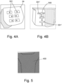
- FIGS 4A and 4B show an example of an air distribution pad 300 that can be used in addition to the first branch 101A, second branch 101B and third branch 101C of Figure 1 .
- the air distribution pad 300 is shown here to be in the interior of the seat cushion.
- the air distribution pad 300 may include one or more nozzles 301 for expelling air to the seat cushion 24.
- the air distribution pad 300 may include one or more branches 301' for providing air flow to the one or more nozzles 301.
- the air distribution pad 300 may be fluidly connected to the first branch 101A, the second branch 101B and/or the third branch 101C shown in Figure 1 .
- the air distribution pad 300 alternatively may be fluidly connected to the sub-branches 102A, 102B, 103A, 103B, 104A and 104B.
- Figure 5 shows an example of the material 400 which is provided over the seat.
- the material 400 may be perforated to allow for the air to expel through the seat material 400.
- the material 400 may be perforated leather.
- the material 400 is not limited to leather.
- there may be provided an air spacer material (not shown) between the material 400 and the outlets 01... 06 or plurality of holed that expel air. In this way, the air spacer material acts as a mesh to prevent passengers from blocking the outlet whilst sitting in the seat.
Claims (14)
- Système individuel de chauffage, ventilation et climatisation (HVAC) pour un siège d'aéronef, comprenant :une pluralité de sièges d'aéronef (10A, 10B, 10C) ;un dispositif de chauffage/refroidissement (100) disposé sur la pluralité de sièges d'aéronef (10A, 10B, 10C) ;une pluralité de branches (101A, 101B, 101C) configurées pour fournir une pluralité de trajets d'écoulement à partir du dispositif de chauffage/refroidissement (100) ;une pluralité de sous-branches (102A, 102B, 103A, 103B, 104A, 104B) prévues dans la pluralité de sièges d'aéronef (10A, 10B, 10C), dans lequel la pluralité de sous-branches (102A, 102B, 103A, 103B, 104A, 104B) sont configurées pour fournir un flux depuis la pluralité de branches (101A, 101B, 101C) à travers la pluralité de sièges d'aéronef (10A, 10B, 10C) ; etun moyen d'expulsion d'air de la pluralité de sous-branches (102A, 102B, 103A, 103B, 104A, 104B) vers une surface intérieure de la pluralité de sièges d'aéronef (10A, 10B, 10C).
- Système individuel de HVAC selon la revendication 1, dans lequel le dispositif de chauffage/refroidissement (100) est l'une d'une combinaison d'au moins un dispositif thermoélectrique et d'au moins un ventilateur, ou d'une combinaison d'au moins un coussin chauffant et d'au moins un ventilateur.
- Système individuel de HVAC selon la revendication 1 ou 2, dans lequel le moyen d'expulsion d'air comporte l'une d'au moins une sortie (01...06) et/ou une pluralité de trous.
- Système individuel de HVAC selon une quelconque revendication précédente, dans lequel la pluralité de sièges d'aéronef comporte au moins l'un d'un coussin de siège, d'un support de dossier de siège, d'un support de nuque de siège et/ou d'un appui-tête.
- Système individuel de HVAC selon une quelconque revendication précédente, dans lequel la pluralité de sièges d'aéronef comporte un premier siège (10A), un deuxième siège (10B) et un troisième siège (10C).
- Système individuel de HVAC selon une quelconque revendication précédente, dans lequel la pluralité de branches comprend une première branche (101A), une deuxième branche (101B) et une troisième branche (101C).
- Système individuel de HVAC selon la revendication 6, dans lequel la première branche (101A) a une première sous-branche (102A), une seconde sous-branche (102B), et dans lequel la deuxième branche (101B) a une première sous-branche (103A) et une seconde sous-branche (103B), et dans lequel la troisième branche (101C) a une première sous-branche (104A) et une seconde sous-branche (104B).
- Système individuel de HVAC selon une quelconque revendication précédente, dans lequel le dispositif de chauffage/refroidissement (100) est commandé par un dispositif de commande.
- Système individuel de HVAC selon la revendication 8, comprenant en outre :des commandes mécaniques manuelles pour ajuster le dispositif de chauffage/refroidissement (100) par l'intermédiaire du dispositif de commande ; et/ouune tablette connectée à un système de commande avancé pour ajuster le dispositif de chauffage/refroidissement (100) ; et/ouun téléphone intelligent connecté à un système de commande avancé pour ajuster le dispositif de chauffage/refroidissement (100) .
- Système individuel de HVAC selon une quelconque revendication précédente, dans lequel la pluralité de sous-branches est ajustable.
- Système individuel de HVAC selon une quelconque revendication précédente, dans lequel la pluralité de sièges d'aéronef comporte un matériau (400) prévu sur le siège, et dans lequel il est prévu un matériau d'espacement d'air prévu entre le matériau (400) et le moyen d'expulsion d'air.
- Cabine d'aéronef comprenant au moins un système individuel de HVAC selon une quelconque revendication précédente.
- Procédé, comprenant :le fait de prévoir une pluralité de sièges d'aéronef (10A, 10B, 10C) ;le fait de prévoir un dispositif de chauffage/refroidissement (100) sur la pluralité de sièges d'aéronef (10A, 10B, 10C) ;le fait de prévoir une pluralité de branches (101A, 101B, 101C) qui fournissent une pluralité de trajets à partir du dispositif de chauffage/refroidissement (100) ;le fait de prévoir une pluralité de sous-branches (102A, 102B, 103A, 103B, 104A, 104B) dans la pluralité de sièges d'aéronef (10A, 10B, 10C), dans lequel la pluralité de sous-branches (102A, 102B, 103A, 103B, 104A, 104B) fournissent un flux depuis la pluralité de branches (101A, 101B, 101C) à travers la pluralité de sièges d'aéronef (10A, 10B, 10C) ; etl'expulsion d'air de la pluralité de sous-branches (102A, 102B, 103A, 103B, 104A, 104B) vers une surface intérieure de la pluralité de sièges d'aéronef (10A, 10B, 10C).
- Procédé selon la revendication 13, dans lequel le dispositif de chauffage/refroidissement (100) est l'une d'une combinaison d'au moins un dispositif thermoélectrique et d'au moins un ventilateur, ou d'une combinaison d'au moins un coussin chauffant et d'au moins un ventilateur.
Applications Claiming Priority (1)
| Application Number | Priority Date | Filing Date | Title |
|---|---|---|---|
| GBGB2005138.9A GB202005138D0 (en) | 2020-04-07 | 2020-04-07 | Personal heating ventilation and air conditioning system in aircraft seat |
Publications (2)
| Publication Number | Publication Date |
|---|---|
| EP3892541A1 EP3892541A1 (fr) | 2021-10-13 |
| EP3892541B1 true EP3892541B1 (fr) | 2023-08-23 |
Family
ID=70768828
Family Applications (1)
| Application Number | Title | Priority Date | Filing Date |
|---|---|---|---|
| EP21166984.1A Active EP3892541B1 (fr) | 2020-04-07 | 2021-04-06 | Système de ventilation et de climatisation du chauffage individuel dans le siège d'un aéronef |
Country Status (3)
| Country | Link |
|---|---|
| US (1) | US20210309373A1 (fr) |
| EP (1) | EP3892541B1 (fr) |
| GB (1) | GB202005138D0 (fr) |
Families Citing this family (1)
| Publication number | Priority date | Publication date | Assignee | Title |
|---|---|---|---|---|
| US20220135235A1 (en) * | 2020-10-29 | 2022-05-05 | The Boeing Company | Ventilation systems and methods for internal cabins of vehicles |
Family Cites Families (21)
| Publication number | Priority date | Publication date | Assignee | Title |
|---|---|---|---|---|
| US5002336A (en) * | 1989-10-18 | 1991-03-26 | Steve Feher | Selectively cooled or heated seat and backrest construction |
| US5617811A (en) * | 1996-01-23 | 1997-04-08 | Johnson; Brian | Temperature regulated seat pad for a motor boat |
| JP2004082961A (ja) * | 2002-08-28 | 2004-03-18 | Johnson Controls Automotive Systems Corp | 乗り物用シート |
| DE10316275B4 (de) * | 2003-04-08 | 2009-06-18 | Johnson Controls Gmbh | Fahrzeugsitz |
| WO2006117690A2 (fr) * | 2005-02-17 | 2006-11-09 | W.E.T. Automotive Systems Ag | Systemes de ventilation active pour sieges de vehicules |
| WO2006124835A1 (fr) * | 2005-05-16 | 2006-11-23 | Amerigon, Inc. | Appuie-tete ventile |
| DE102006041030B4 (de) * | 2006-09-01 | 2014-11-20 | Airbus Operations Gmbh | Luftfahrzeug-Klimatisierungssystem zum individuellen Klimatisieren von Bereichen einer Luftfahrzeugkabine mit einem flüssigen Kühlmittel |
| US20090218855A1 (en) * | 2008-02-26 | 2009-09-03 | Amerigon Incorporated | Climate control systems and devices for a seating assembly |
| US10029797B2 (en) * | 2008-09-30 | 2018-07-24 | The Boeing Company | Personal ventilation in an aircraft environment |
| DE102009006758A1 (de) * | 2009-01-30 | 2010-08-05 | Lufthansa Technik Ag | Sitz für ein Verkehrsmittel |
| US20120017371A1 (en) * | 2010-07-26 | 2012-01-26 | Pollard Jan M | Blanket having two independently controlled cooling zones |
| US20160059954A1 (en) * | 2013-01-31 | 2016-03-03 | Bombardier Inc. | System and a method of operation of the system incorporating a graphical user interface on a mobile computing device for a passenger in a vehicle cabin |
| US20170115039A1 (en) | 2015-10-21 | 2017-04-27 | Ami Industries, Inc. | Thermoelectric based heat pump configuration |
| BR112019017315B1 (pt) * | 2017-03-01 | 2023-03-07 | Ts Tech Co., Ltd | Assento de veículo |
| US10974619B2 (en) * | 2017-03-28 | 2021-04-13 | Ts Tech Co., Ltd. | Vehicle seat and passenger selection system |
| JP6766762B2 (ja) * | 2017-06-22 | 2020-10-14 | 株式会社デンソー | シート空調システム |
| US11075331B2 (en) * | 2018-07-30 | 2021-07-27 | Gentherm Incorporated | Thermoelectric device having circuitry with structural rigidity |
| GB2580026B (en) * | 2018-12-19 | 2023-02-22 | Safran Seats Gb Ltd | Aircraft seat |
| CN209987795U (zh) * | 2019-06-13 | 2020-01-24 | 北京浩雨固定式护颈托枕科技有限公司 | 一种护颈枕 |
| US10889378B1 (en) * | 2019-08-23 | 2021-01-12 | B/E Aerospace, Inc. | System for heating and cooling a seat and seat assemblies |
| US20230002060A1 (en) * | 2021-06-30 | 2023-01-05 | The Boeing Company | Ventilation assembly in an aircraft |
-
2020
- 2020-04-07 GB GBGB2005138.9A patent/GB202005138D0/en not_active Ceased
-
2021
- 2021-04-02 US US17/221,069 patent/US20210309373A1/en active Pending
- 2021-04-06 EP EP21166984.1A patent/EP3892541B1/fr active Active
Also Published As
| Publication number | Publication date |
|---|---|
| EP3892541A1 (fr) | 2021-10-13 |
| GB202005138D0 (en) | 2020-05-20 |
| US20210309373A1 (en) | 2021-10-07 |
Similar Documents
| Publication | Publication Date | Title |
|---|---|---|
| CN106143242B (zh) | 具有非对称热管理系统和方法的增强型气候座椅 | |
| EP2329988B1 (fr) | Ensemble siège à régulation climatique | |
| EP2607155B1 (fr) | Système de gestion du flux d'air pour siège de véhicule | |
| US7827805B2 (en) | Seat climate control system | |
| US20070001489A1 (en) | Vehicle seat with thermal elements | |
| DE112014004376T5 (de) | Luftversorgungskomponente für einen Fahrzeugsitz | |
| US11161437B2 (en) | Seat heat and ventilation systems and vehicle seat assemblies | |
| US11524784B2 (en) | Ventilated seat assembly with active air flow | |
| EP3892541B1 (fr) | Système de ventilation et de climatisation du chauffage individuel dans le siège d'un aéronef | |
| US11383842B2 (en) | Ventilated vehicle seat systems and methods | |
| WO2015027974A1 (fr) | Dispositif de régulation et procédé de commande de systèmes de chauffage d'habitacle de véhicule | |
| US10647231B2 (en) | Ventilated airline seating component | |
| US20230140582A1 (en) | Air conditioning system | |
| EP3848284B1 (fr) | Systèmes de chauffage et de ventilation de siège et ensembles sièges de véhicule | |
| US20230256877A1 (en) | Ventilated seat with perforated electroconductive fabric heating elements | |
| EP3964442B1 (fr) | Appuie-tête réglable ventilé | |
| KR20230059613A (ko) | 차량 시트 구조를 활용한 개인별 차량 공조 시스템 | |
| JPH10315962A (ja) | 車両用空調装置 | |
| CZ29593U1 (cs) | Vrchní potahová textilie automobilové sedačky |
Legal Events
| Date | Code | Title | Description |
|---|---|---|---|
| PUAI | Public reference made under article 153(3) epc to a published international application that has entered the european phase |
Free format text: ORIGINAL CODE: 0009012 |
|
| STAA | Information on the status of an ep patent application or granted ep patent |
Free format text: STATUS: THE APPLICATION HAS BEEN PUBLISHED |
|
| AK | Designated contracting states |
Kind code of ref document: A1 Designated state(s): AL AT BE BG CH CY CZ DE DK EE ES FI FR GB GR HR HU IE IS IT LI LT LU LV MC MK MT NL NO PL PT RO RS SE SI SK SM TR |
|
| RAP1 | Party data changed (applicant data changed or rights of an application transferred) |
Owner name: UNITED TECHNOLOGIES RESEARCH CENTRE IRELAND, LIMITED |
|
| STAA | Information on the status of an ep patent application or granted ep patent |
Free format text: STATUS: REQUEST FOR EXAMINATION WAS MADE |
|
| RAP3 | Party data changed (applicant data changed or rights of an application transferred) |
Owner name: COLLINS AEROSPACE IRELAND, LIMITED |
|
| 17P | Request for examination filed |
Effective date: 20220412 |
|
| RBV | Designated contracting states (corrected) |
Designated state(s): AL AT BE BG CH CY CZ DE DK EE ES FI FR GB GR HR HU IE IS IT LI LT LU LV MC MK MT NL NO PL PT RO RS SE SI SK SM TR |
|
| GRAP | Despatch of communication of intention to grant a patent |
Free format text: ORIGINAL CODE: EPIDOSNIGR1 |
|
| STAA | Information on the status of an ep patent application or granted ep patent |
Free format text: STATUS: GRANT OF PATENT IS INTENDED |
|
| INTG | Intention to grant announced |
Effective date: 20230314 |
|
| GRAS | Grant fee paid |
Free format text: ORIGINAL CODE: EPIDOSNIGR3 |
|
| GRAA | (expected) grant |
Free format text: ORIGINAL CODE: 0009210 |
|
| STAA | Information on the status of an ep patent application or granted ep patent |
Free format text: STATUS: THE PATENT HAS BEEN GRANTED |
|
| AK | Designated contracting states |
Kind code of ref document: B1 Designated state(s): AL AT BE BG CH CY CZ DE DK EE ES FI FR GB GR HR HU IE IS IT LI LT LU LV MC MK MT NL NO PL PT RO RS SE SI SK SM TR |
|
| REG | Reference to a national code |
Ref country code: GB Ref legal event code: FG4D |
|
| REG | Reference to a national code |
Ref country code: CH Ref legal event code: EP |
|
| REG | Reference to a national code |
Ref country code: DE Ref legal event code: R096 Ref document number: 602021004423 Country of ref document: DE |
|
| REG | Reference to a national code |
Ref country code: IE Ref legal event code: FG4D |
|
| REG | Reference to a national code |
Ref country code: LT Ref legal event code: MG9D |
|
| REG | Reference to a national code |
Ref country code: NL Ref legal event code: MP Effective date: 20230823 |
|
| REG | Reference to a national code |
Ref country code: AT Ref legal event code: MK05 Ref document number: 1602338 Country of ref document: AT Kind code of ref document: T Effective date: 20230823 |
|
| PG25 | Lapsed in a contracting state [announced via postgrant information from national office to epo] |
Ref country code: GR Free format text: LAPSE BECAUSE OF FAILURE TO SUBMIT A TRANSLATION OF THE DESCRIPTION OR TO PAY THE FEE WITHIN THE PRESCRIBED TIME-LIMIT Effective date: 20231124 |
|
| PG25 | Lapsed in a contracting state [announced via postgrant information from national office to epo] |
Ref country code: IS Free format text: LAPSE BECAUSE OF FAILURE TO SUBMIT A TRANSLATION OF THE DESCRIPTION OR TO PAY THE FEE WITHIN THE PRESCRIBED TIME-LIMIT Effective date: 20231223 |
|
| PG25 | Lapsed in a contracting state [announced via postgrant information from national office to epo] |
Ref country code: SE Free format text: LAPSE BECAUSE OF FAILURE TO SUBMIT A TRANSLATION OF THE DESCRIPTION OR TO PAY THE FEE WITHIN THE PRESCRIBED TIME-LIMIT Effective date: 20230823 Ref country code: RS Free format text: LAPSE BECAUSE OF FAILURE TO SUBMIT A TRANSLATION OF THE DESCRIPTION OR TO PAY THE FEE WITHIN THE PRESCRIBED TIME-LIMIT Effective date: 20230823 Ref country code: PT Free format text: LAPSE BECAUSE OF FAILURE TO SUBMIT A TRANSLATION OF THE DESCRIPTION OR TO PAY THE FEE WITHIN THE PRESCRIBED TIME-LIMIT Effective date: 20231226 Ref country code: NO Free format text: LAPSE BECAUSE OF FAILURE TO SUBMIT A TRANSLATION OF THE DESCRIPTION OR TO PAY THE FEE WITHIN THE PRESCRIBED TIME-LIMIT Effective date: 20231123 Ref country code: NL Free format text: LAPSE BECAUSE OF FAILURE TO SUBMIT A TRANSLATION OF THE DESCRIPTION OR TO PAY THE FEE WITHIN THE PRESCRIBED TIME-LIMIT Effective date: 20230823 Ref country code: LV Free format text: LAPSE BECAUSE OF FAILURE TO SUBMIT A TRANSLATION OF THE DESCRIPTION OR TO PAY THE FEE WITHIN THE PRESCRIBED TIME-LIMIT Effective date: 20230823 Ref country code: LT Free format text: LAPSE BECAUSE OF FAILURE TO SUBMIT A TRANSLATION OF THE DESCRIPTION OR TO PAY THE FEE WITHIN THE PRESCRIBED TIME-LIMIT Effective date: 20230823 Ref country code: IS Free format text: LAPSE BECAUSE OF FAILURE TO SUBMIT A TRANSLATION OF THE DESCRIPTION OR TO PAY THE FEE WITHIN THE PRESCRIBED TIME-LIMIT Effective date: 20231223 Ref country code: HR Free format text: LAPSE BECAUSE OF FAILURE TO SUBMIT A TRANSLATION OF THE DESCRIPTION OR TO PAY THE FEE WITHIN THE PRESCRIBED TIME-LIMIT Effective date: 20230823 Ref country code: GR Free format text: LAPSE BECAUSE OF FAILURE TO SUBMIT A TRANSLATION OF THE DESCRIPTION OR TO PAY THE FEE WITHIN THE PRESCRIBED TIME-LIMIT Effective date: 20231124 Ref country code: FI Free format text: LAPSE BECAUSE OF FAILURE TO SUBMIT A TRANSLATION OF THE DESCRIPTION OR TO PAY THE FEE WITHIN THE PRESCRIBED TIME-LIMIT Effective date: 20230823 Ref country code: AT Free format text: LAPSE BECAUSE OF FAILURE TO SUBMIT A TRANSLATION OF THE DESCRIPTION OR TO PAY THE FEE WITHIN THE PRESCRIBED TIME-LIMIT Effective date: 20230823 |
|
| PG25 | Lapsed in a contracting state [announced via postgrant information from national office to epo] |
Ref country code: PL Free format text: LAPSE BECAUSE OF FAILURE TO SUBMIT A TRANSLATION OF THE DESCRIPTION OR TO PAY THE FEE WITHIN THE PRESCRIBED TIME-LIMIT Effective date: 20230823 |
|
| PG25 | Lapsed in a contracting state [announced via postgrant information from national office to epo] |
Ref country code: ES Free format text: LAPSE BECAUSE OF FAILURE TO SUBMIT A TRANSLATION OF THE DESCRIPTION OR TO PAY THE FEE WITHIN THE PRESCRIBED TIME-LIMIT Effective date: 20230823 |
|
| PG25 | Lapsed in a contracting state [announced via postgrant information from national office to epo] |
Ref country code: SM Free format text: LAPSE BECAUSE OF FAILURE TO SUBMIT A TRANSLATION OF THE DESCRIPTION OR TO PAY THE FEE WITHIN THE PRESCRIBED TIME-LIMIT Effective date: 20230823 Ref country code: RO Free format text: LAPSE BECAUSE OF FAILURE TO SUBMIT A TRANSLATION OF THE DESCRIPTION OR TO PAY THE FEE WITHIN THE PRESCRIBED TIME-LIMIT Effective date: 20230823 Ref country code: ES Free format text: LAPSE BECAUSE OF FAILURE TO SUBMIT A TRANSLATION OF THE DESCRIPTION OR TO PAY THE FEE WITHIN THE PRESCRIBED TIME-LIMIT Effective date: 20230823 Ref country code: EE Free format text: LAPSE BECAUSE OF FAILURE TO SUBMIT A TRANSLATION OF THE DESCRIPTION OR TO PAY THE FEE WITHIN THE PRESCRIBED TIME-LIMIT Effective date: 20230823 Ref country code: DK Free format text: LAPSE BECAUSE OF FAILURE TO SUBMIT A TRANSLATION OF THE DESCRIPTION OR TO PAY THE FEE WITHIN THE PRESCRIBED TIME-LIMIT Effective date: 20230823 Ref country code: CZ Free format text: LAPSE BECAUSE OF FAILURE TO SUBMIT A TRANSLATION OF THE DESCRIPTION OR TO PAY THE FEE WITHIN THE PRESCRIBED TIME-LIMIT Effective date: 20230823 Ref country code: SK Free format text: LAPSE BECAUSE OF FAILURE TO SUBMIT A TRANSLATION OF THE DESCRIPTION OR TO PAY THE FEE WITHIN THE PRESCRIBED TIME-LIMIT Effective date: 20230823 |