EP3892494A1 - Fahrgasttisch - Google Patents
Fahrgasttisch Download PDFInfo
- Publication number
- EP3892494A1 EP3892494A1 EP21160964.9A EP21160964A EP3892494A1 EP 3892494 A1 EP3892494 A1 EP 3892494A1 EP 21160964 A EP21160964 A EP 21160964A EP 3892494 A1 EP3892494 A1 EP 3892494A1
- Authority
- EP
- European Patent Office
- Prior art keywords
- axis
- extension plate
- table top
- lever
- passenger
- Prior art date
- Legal status (The legal status is an assumption and is not a legal conclusion. Google has not performed a legal analysis and makes no representation as to the accuracy of the status listed.)
- Granted
Links
Images


Classifications
-
- B—PERFORMING OPERATIONS; TRANSPORTING
- B60—VEHICLES IN GENERAL
- B60N—SEATS SPECIALLY ADAPTED FOR VEHICLES; VEHICLE PASSENGER ACCOMMODATION NOT OTHERWISE PROVIDED FOR
- B60N3/00—Arrangements or adaptations of other passenger fittings, not otherwise provided for
- B60N3/001—Arrangements or adaptations of other passenger fittings, not otherwise provided for of tables or trays
-
- B—PERFORMING OPERATIONS; TRANSPORTING
- B61—RAILWAYS
- B61D—BODY DETAILS OR KINDS OF RAILWAY VEHICLES
- B61D37/00—Other furniture or furnishings
Definitions
- the invention relates to a passenger table, in particular for vehicles for passenger transport such as rail vehicles, with a stationary table top and a table extension plate, which is moved by means of a gear from a retracted position below the table top into a position of use in which the table extension plate is attached to an associated outer edge of the table top connects, is transferable.
- Such a passenger table is, for example, from DE 10 2015 204 705 A1 known.
- passenger tables on seating groups of rail vehicles are limited in their fixed depth in order to keep enough space free for access to passenger seats.
- the table extension plate is used, which in its use position directly adjoins the fixed table top and thus provides a larger table surface overall.
- a gear for controlling the movement of the table extension plate relative to the stationary table top is typically chosen so that the table extension plate comes to lie flush with the stationary table top in its use / end position.
- the invention is based on the object of further developing a passenger table of the type mentioned at the beginning in such a way that suitable support for the table extension plate can be achieved in its position of use.
- a passenger table with the features of claim 1.
- the transmission is designed as a flat cam gear arranged below the table top, with a first cam roller on a first stationary opposite the table top Guide track rolls off, and a movement of the linear cam mechanism via a planar pantograph mechanism, which has a first coupling point rotatably connected to the table extension plate and a second coupling point fixed relative to the table top, is scaled in such a way that the first coupling point on the table extension plate when moving the table extension plate from the retracted position to the position of use or vice versa covers a longer trajectory in space than the first cam roller.
- the second, third, fifth and sixth axes preferably form at least approximately the shape of a parallelogram. Deviations from the shape of a parallelogram can result in particular from the fact that boundary conditions due to the available installation space have to be taken into account.
- a suitable scaling of the movement of the linear cam mechanism results in particular when the distance between the second axis and the first axis is less than the distance between the third axis and the first axis (ratio, for example, 40 to 60%).
- the distance between the fourth axis and the second axis can be less than the distance between the seventh axis and the third axis (ratio, for example, 30 to 60%).
- a further gear is preferably provided to define a rotary position of the table extension plate around the first coupling point.
- This can be one on the table extension plate have mounted second cam roller, which rolls on a stationary opposite the table top second guide track.
- a wide support base for the table extension plate results from the favorable distance between the first coupling point and the second cam roller of the further gear when the table extension plate is in its position of use.
- the first axis, the fourth axis and a seventh axis of the first coupling point, about which the table extension plate can be rotated relative to the second lever, can be arranged approximately in all planes.
- the trajectory of the guide roller is mathematically similar to that of the coupling point.
- the guide curve can thus be constructed directly from the construction of the curve of the coupling point. This can be particularly advantageous when the guideway is to be made from simple elements such as straight lines and arcs.
- the fourth and the fifth axis coincide on the roller carrier.
- the advantage here is a combination of functions: only one hole in the roller carrier would be required.
- the bearing journal of the cam roller is also the pivot pin of the fifth axis. In this embodiment, however, no standard component can be used for the cam roller. A longer lever to the fifth and sixth axis would reduce joint forces.
- a base body can be attached to the table top, in which the first and second guide tracks are each designed as a groove and which has a bearing for the first axis. Such a base body thus ensures that the guideways and the position of the first axis are stationary with respect to the table top.
- the design of the guideways as grooves in the preferably flat base body allows free design of the trajectories for the cam rollers and enables them to be free of charge such an optimization for intuitive haptics in operation and narrow gaps across the entire range of motion.
- the kinematics provided can also ensure that the table extension plate can be pushed in without significant forces in the event of a collision with passengers. This means that there is no need to consider the case in the extended position with regard to a further impact scenario and the reduced survival space on the opposite side.
- Figure 1 shows an edge section of a table top 1 which is fixedly mounted in a vehicle for passenger transport, for example a rail vehicle, the edge section of the table top 1 facing a passenger seat (not shown).
- a table extension plate 2 adjoins the stationary table top 1 in the direction of the passenger seat when the latter is in its position of use, ie forms an extension of the available surface of the passenger table.
- the table extension plate 2 can be moved relative to the stationary table top 1 via a gear mechanism.
- a flat base body 3 is provided, which is inserted into the table top 1 and attached to it.
- the design of the base body 3 determines, as will be explained in more detail later, the relative movement of the table extension plate 2 with respect to the table top 1.
- the table extension plate 2 is connected to the table top 1 via a flat pantograph mechanism which is arranged vertically when the passenger table is installed and which comprises a first lever 4, a second lever 5, a roller carrier 6 which carries a cam roller 7, and a link 9 .
- the first lever 4 is rotatably hinged to the base body 3 and thus to the stationary table top 1 by means of a first axis 4.1, namely in the lower area of the table top 1. Furthermore, the lever 4 is rotatable via a second axis 4.2 with the roller carrier 6 and connected to the second lever 5 via an axis 4.3.
- the pantograph mechanism is completed in that the roller carrier 6, which carries the first guide roller 7 on a fourth axis 7.1, is connected to the link 9 via a fifth axle 9.1, while the link 9 is rotatable with the second via a sixth axle 9.2 Lever 5 is connected.
- the second, third, fifth and sixth axes form a parallelogram, as is typical for the formation of a pantograph mechanism.
- the lever 5 has a first coupling point 5.2 at its end facing the table extension plate 2, the table extension plate 2 being rotatably connected to the second lever 5 about a seventh axis 5.1 in its area.
- a second coupling point 4.4 is provided, which is characterized by the first axis 4.1, which allows a rotary movement of the first lever 4 relative to the table top 1.
- the first axis 4.1, the fourth axis 7.1 and a seventh axis 5.1 of the first coupling point, about which the table extension plate 2 can be rotated relative to the second lever 5, are arranged in one plane. Slight deviations from this level are permitted. It is also possible for the fourth and fifth axes 7.1, 9.1 to coincide on the roller carrier 6 in alternative embodiments.
- An essential part of the gear is an approximately horizontally running linear cam gear, in which the first cam roller 7 rolls on a first guide track 8 which is formed by a groove provided in the base body 3.
- a rotary movement of the table extension plate 2 around the seventh axis 5.1 of the first coupling point 5.2 is determined by a further gear which comprises a second cam roller 10 which is rotatably mounted on the table extension plate 2 via an eighth axis 10.1 and which is also in a groove in the base body 3 formed second guide track 11 rolls.
- the transmission designed in this way allows the first coupling point 5.1 to perform movements that are clearly outside the table top 1 lie. In this way, a wide support base is achieved for the second cam roller 10.
- the pantograph mechanism is also determined by the fact that the distance between the second axis 4.2 and the first axis 4.1 is significantly less than the distance between the third axis 4.3 and the first axis 4.1 Fig. 1 illustrated position of use of the table extension plate 2, the distance between the fourth axis 7.1 from the third axis 4.3 less than the distance between the fourth axis 7.1 from the second axis 4.2. In general, the distance between the fourth axis 7.1 and the second axis 4.2 is less than the distance between the seventh axis 5.1 and the third axis 4.3.
- first cam roller 7 and the second cam roller 10 are located within their respective guide tracks 8, 11 in an end position which is assigned to the position of use of the table extension plate 2.
- Figure 1 shows the relative arrangement of the table top 1 to the table extension plate 2 in the state of use of the table extension plate 2, in which surfaces of the table top 1 and the table extension plate 2 are aligned with one another Figure 2 an intermediate position of the table extension plate 2, in which it is already a first distance in the direction of the in Figure 3 has moved the retracted position shown.
- a comparison of the Figures 1 and 2 shows that the first cam roller 7 has moved slightly horizontally inward of the table top 1 along the guide track 8, while the second guide roller 10 has moved out of its in Figure 1 end position shown, based on the table top 1, has completed a movement obliquely downward and inward of the table top 1.
- the respective positions of the first lever 4, the second lever 5, the roller carrier 6 and the link 9 follow the movement of the first cam roller 7 along the first guide track 8 and thus determine the position of the first coupling point 4.4.
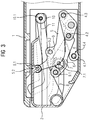
- Figure 3 shows the table extension plate 2 in its retracted position below the table top 1, the table extension plate 2 being completely received in the table top 1, the table top 1 and the table extension plate 2 forming an essentially coherent end face on their sides facing a passenger seat.
- the first cam roller 7 has reached its end position in the first guide track 8 and compared to Figure 2 made an essentially horizontal, linear movement.
- the second cam roller 10 is now in its end position in the second guide track 11 and, compared to FIG Figure 2 performs a slightly inclined upward movement inward of the table top 1.
Landscapes
- Engineering & Computer Science (AREA)
- Mechanical Engineering (AREA)
- Transportation (AREA)
- Chair Legs, Seat Parts, And Backrests (AREA)
- Passenger Equipment (AREA)
- Vehicle Step Arrangements And Article Storage (AREA)
Abstract
Description
- Die Erfindung bezieht sich auf einen Fahrgasttisch, insbesondere für Fahrzeuge zur Personenbeförderung wie Schienenfahrzeuge, mit einer ortsfesten Tischplatte und einer Tischauszugsplatte, die mittels eines Getriebes aus einer zurückgezogenen Position unterhalb der Tischplatte in eine Gebrauchsposition bei der sich die Tischauszugsplatte an eine zugeordnete äußere Kante der Tischplatte anschließt, überführbar ist.
- Ein solcher Fahrgasttisch ist beispielsweise aus der
DE 10 2015 204 705 A1 bekannt. Beispielsweise Fahrgasttisch an Sitzgruppen von Schienenfahrzeugen sind in ihrer festen Tiefe begrenzt, um genügend Raum für einen Zugang zu Fahrgastsitzen freizuhalten. Um dennoch eine nutzbare Tischfläche nahe an die Sitzposition heranführen zu können, wird die Tischauszugsplatte verwendet, die sich in ihrer Gebrauchsposition unmittelbar die feste Tischplatte anschließt und somit insgesamt eine größere verfügbare Tischfläche bereitstellt. Dabei ist ein Getriebe zum Steuern der Bewegung der Tischauszugsplatte relativ zu der ortsfesten Tischplatte typischerweise so gewählt, dass die Tischauszugsplatte in ihrer Gebrauchs-/Endposition bündig mit der ortsfesten Tischplatte zu liegen kommt. - Dabei ist zu berücksichtigen, dass aufgrund der erforderlichen tragenden Struktur der Tischplatte ein Bauraum zur Unterbringung des Getriebes typischerweise sehr beschränkt ist.
- Beim Einsatz von Linearführungen für die Tischauszugsplatte wird es problematisch, wenn ein innerhalb der ortsfesten Tischplatte vorhandener Bauraum nur wenig größer als eine Auszugslänge der Tischauszugsplatte ist. Die Biegemomente aus einer vertikalen Belastung der Tischauszugsplatte in ihrer Gebrauchsposition müssen somit auf einer sehr kurzen Basis aufgenommen werden, was hohe innere Kräfte in der Führung bewirkt. Insofern besteht die Gefahr, dass zur Führung der Tischauszugsplatte eingesetzte Komponenten überlastet werden, bei Gleitführungen insbesondere eine Selbsthemmung droht.
- Ausgehend hiervon liegt der Erfindung die Aufgabe zugrunde, einen Fahrgasttisch der eingangs genannten Art derart weiterzuentwickeln, dass eine geeignete Abstützung für die Tischauszugsplatte in ihrer Gebrauchsposition erzielbar ist.
- Diese Aufgabe wird gelöst durch einen Fahrgasttisch mit den Merkmalen des Anspruchs 1. Dieser zeichnet sich gegenüber dem eingangs beschriebenen Fahrgasttisch dadurch aus, dass das Getriebe als unterhalb der Tischplatte angeordnetes ebenes Kurvengetriebe ausgebildet ist, bei dem eine erste Kurvenrolle auf einer gegenüber der Tischplatte ortfesten ersten Führungsbahn abrollt, und eine Bewegung des linearen Kurvengetriebes über einen ebenen Pantographen-Mechanismus, der einen mit der Tischauszugsplatte drehbar verbundenen ersten Koppelpunkt und einen gegenüber der Tischplatte ortsfesten zweiten Koppelpunkt aufweist, derart skaliert ist, dass der erste Koppelpunkt an der Tischauszugsplatte beim Verbringen der Tischauszugsplatte aus der zurückgezogenen Position in die Gebrauchsposition oder umgekehrt eine längere Bahnkurve im Raum zurücklegt als die erste Kurvenrolle.
- Durch die Skalierung der Bewegung des linearen Kurvengetriebes mit Hilfe des Pantographen-Mechanismus ist es möglich, dass der erste Koppelpunkt Bewegungen ausführen kann, die deutlich außerhalb der Tischplatte liegen. Damit wird eine breite Abstützbasis für die Tischauszugsplatte erzielbar, was interne Kräfte auf praktikable Werte begrenzt.
- Bevorzugt weist der Pantographen-Mechanismus auf:
- einen ersten Hebel, der an dem zweiten Koppelpunkt um eine erste Achse drehbar gelagert ist,
- einen zweiten Hebel, der mit dem ersten Hebel um eine dritte Achse drehbar verbunden ist und an seinem, der Tischauszugsplatte zugewandten Ende den ersten Koppelpunkt trägt, und entweder
- einen Rollenträger, der um eine zweite Achse mit dem ersten Hebel drehbar verbunden ist und an dem die erste Kurvenrolle um eine vierte Achse drehbar gelagert ist, und
- einen Lenker, der mit dem Rollenträger um eine fünfte Achse und mit dem zweiten Hebel um eine sechste Achse drehbar verbunden ist, oder
- einen Lenker, der um eine zweite Achse mit dem ersten Hebel drehbar verbunden ist, und
- einen Rollenträger, der mit dem Lenker um eine fünfte Achse drehbar verbunden ist, mit dem zweiten Hebel um eine sechste Achse drehbar verbunden ist und an dem die Kurvenrolle um eine vierte Achse drehbar gelagert ist.
- Die beschriebene Anordnung von Hebeln, Lenker und Rollenträger bildet einen typischen Pantographen-Mechanismus aus. Zu berücksichtigen ist, dass die Positionen des Lenkers und des Rollenträgers in dem Pantographen-Mechanismus auch vertauscht sein können.
- Vorzugsweise bilden die zweite, dritte, fünfte und sechste Achse wenigstens annähernd die Form eines Parallelogramms aus. Abweichungen von der Form eines Parallelogramms können sich insbesondere dadurch ergeben, dass Randbedingungen durch den vorhandenen Bauraum zu berücksichtigen sind.
- Ein geeignete Skalierung der Bewegung des linearen Kurvengetriebes ergibt sich insbesondere dann, wenn der Abstand der zweiten Achse von der ersten Achse geringer als der Abstand der dritten Achse von der ersten Achse ist (Verhältnis z. B. 40 bis 60%). Dabei kann der Abstand der vierten Achse von der zweiten Achse geringer als der Abstand der siebten Achse von der dritten Achse sein (Verhältnis z. B. 30 bis 60%).
- Bevorzugt ist zur Definition einer rotatorischen Lage der Tischauszugsplatte um den ersten Koppelpunkt ein weiteres Getriebe vorgesehen. Dieses kann eine an der Tischauszugsplatte gelagerte zweite Kurvenrolle aufweisen, die auf einer gegenüber der Tischplatte ortsfesten zweiten Führungsbahn abrollt. Bei dieser Ausführungsform ergibt sich eine breite Abstützbasis für die Tischauszugsplatte durch den günstigen Abstand zwischen dem ersten Koppelpunkt und der zweiten Kurvenrolle des weiteren Getriebes, wenn sich die Tischauszugsplatte in ihrer Gebrauchsposition befindet.
- Die erste Achse, die vierte Achse und eine siebte Achse des ersten Koppelpunktes, um die die Tischauszugsplatte gegenüber dem zweiten Hebel drehbar ist, können annähernd in aller ebene angeordnet sein. Mit dieser Bedingung ist die Bahnkurve der Führungsrolle derjenigen des Koppelpunktes mathematisch ähnlich.
Aus der Konstruktion der Kurve des Koppelpunktes lässt sich somit direkt die Führungskurve konstruieren.
Dies kann insbesondere dann vorteilhaft sein, wenn die Führungsbahn aus einfachen Elementen wie Geraden und Kreisbögen hergestellt werden soll. - Zudem ist es möglich, dass die vierte und die fünfte Achse an dem Rollenträger zusammenfallen. Vorteil ist hierbei eine Funktionsvereinigung: Nur eine Bohrung im Rollenträger wäre erforderlich. Der Lagerzapfen der Kurvenrolle ist gleichzeitig der Gelenkbolzen der fünften Achse. Allerdings wird bei dieser Ausführungsform für die Kurvenrolle kein Standardbauteil einsetzbar sein. Ein längerer Hebel zur fünften und sechsten Achse würde auftretende Gelenkkräfte reduzieren. An der Tischplatte kann ein Grundkörper befestigt sein, in den die erste und die zweite Führungsbahn jeweils als Nut ausgebildet ist und der eine Lagerung für die erste Achse aufweist. Eine solcher Grundkörper sorgt somit dafür, dass die Führungsbahnen sowie die Position der ersten Achse ortsfest gegenüber der Tischplatte sind.
- Die Ausführung der Führungsbahnen als Nuten in dem vorzugsweise flachen Grundkörper erlaubt kostenneutral eine freie Gestaltung der Bahnkurven für die Kurvenrollen und ermöglicht so eine Optimierung auf intuitive Haptik in der Bedienung und enge Spaltmaße über den gesamten Bewegungsbereich.
- Mit der vorgesehenen Kinematik kann außerdem bewirkt werden, dass sich die Tischauszugsplatte beim Aufprall von Fahrgästen infolge einer Kollision ohne nennenswerte Kräfte einschieben lassen. Damit entfällt die Betrachtung des Falls der ausgezogenen Position hinsichtlich eines weiteren Aufprallszenarios und des reduzierten Überlebensraums auf der Gegenseite.
- Es ist hervorzuheben, dass die vorstehend beschriebene Ausbildung des die Bewegung der Tischauszugsplatte bestimmenden Getriebes baugleich auf beiden Seiten der Tischplatte vorgesehen sein kann. Vorzugsweise nutzen beide Getriebe jeweils einen Grundkörper.
- Ein Ausführungsbeispiel der Erfindung wird nachfolgend unter Bezugnahme auf die Zeichnung noch näher erläutert. Es zeigen:
- Figur 1
- eine schematische Querschnittsansicht einer Tischauszugsplatte in Kombination mit einer ortsfesten Tischplatte, wobei sich die Tischauszugsplatte in einer Gebrauchsposition befindet,
- Figur 2
- eine schematische Querschnittsansicht der Tischauszugsplatte von
Figur 1 in Kombination mit einer ortsfesten Tischplatte, wobei sich die Tischauszugsplatte in einer Zwischenposition befindet, - Figur 3
- eine schematische Querschnittsansicht der Tischauszugsplatte von
Figur 1 in Kombination mit einer ortsfesten Tischplatte, wobei sich die Tischauszugsplatte in einer zurückgezogenen Position befindet und - Figur 4
- eine perspektivische Ansicht auf die Tischauszugsplatte der
Fig. 1 bis 3 mit zugehörigen Getrieben zum Anbau an eine ortsfeste Tischplatte. -
Figur 1 zeigt einen Randabschnitt einer Tischplatte 1, die ortsfest in einem Fahrzeug zur Personenbeförderung, beispielsweise einem Schienenfahrzeug, montiert ist, wobei der Randabschnitt der Tischplatte 1 einem (nicht dargestellten) Fahrgastsitz zugewandt ist. An die ortsfeste Tischplatte 1 schließt sich in Richtung Fahrgastsitz eine Tischauszugsplatte 2 an, wenn letztere sich in ihrer Gebrauchsposition befindet, d.h. eine Erweiterung der verfügbaren Oberfläche des Fahrgasttisches bildet. - Die Tischauszugsplatte 2 ist über ein Getriebe relativ zu der ortsfesten Tischplatte 1 bewegbar. Es ist eine flacher Grundkörper 3 vorgesehen, die in die Tischplatte 1 eingesetzt und an dieser befestigt ist. Die Ausbildung des Grundkörpers 3 bestimmt, wie später mehr im Detail erläutert wird, die relative Bewegung der Tischauszugsplatte 2 gegenüber der Tischplatte 1 mit.
- Die Tischauszugsplatte 2 ist mit der Tischplatte 1 über einen im eingebauten Zustand des Fahrgasttisches vertikal angeordneten, ebenen Pantographen-Mechanismus verbunden, der einen ersten Hebel 4, einen zweiten Hebel 5, einen Rollenträger 6, der eine Kurvenrolle 7 trägt, und einen Lenker 9 umfasst. Dabei ist der erste Hebel 4 mittels einer ersten Achse 4.1 drehbar an den Grundkörper 3 und damit an der ortsfesten Tischplatte 1 angelenkt, und zwar im unteren Bereich der Tischplatte 1. Des Weiteren ist der Hebel 4 jeweils drehbar über eine zweite Achse 4.2 mit dem Rollenträger 6 und über eine Achse 4.3 mit dem zweiten Hebel 5 verbunden. Der Pantographen-Mechanismus wird dadurch vervollständigt, dass der Rollenträger 6, der auf einer vierten Achse 7.1 die erste Führungsrolle 7 trägt, über eine fünfte Achse 9.1 mit dem Lenker 9 verbunden ist, während der Lenker 9 über eine sechste Achse 9.2 drehbar mit dem zweiten Hebel 5 verbunden ist.
- Im dargestellten Ausführungsbeispiel bilden die zweite, dritte, fünfte und sechste Achse ein Parallelogramm aus, wie es für die Ausbildung eines Pantographen-Mechanismus typisch ist.
- Der Hebel 5 weist an seinem der Tischauszugsplatte 2 zugewandten Ende einen ersten Koppelpunkt 5.2 auf, wobei in dessen Bereich die Tischauszugsplatte 2 um eine siebte Achse 5.1 drehbar mit dem zweiten Hebel 5 verbunden ist. Auf der dem ersten Koppelpunkt 5.2 gegenüberliegenden Seite des Pantographen-Mechanismus ist ein zweiter Koppelpunkt 4.4 vorgesehen, der durch die erste Achse 4.1 gekennzeichnet ist, die eine Drehbewegung des ersten Hebels 4 relativ zur Tischplatte 1 gestattet.
- Es ist ersichtlich, dass im dargestellten Ausführungsbeispiel die erste Achse 4.1, die vierte Achse 7.1 und eine siebte Achse 5.1 des ersten Koppelpunktes, um die die Tischauszugsplatte 2 gegenüber dem zweiten Hebel 5 drehbar ist, in einer Ebene angeordnet sind. Geringfügige Abweichungen von dieser Ebene sind zulässig. Auch ist es möglich, dass bei alternativen Ausführungsformen die vierte und die fünfte Achse 7.1, 9.1 an dem Rollenträger 6 zusammenfallen.
- Wesentlicher Teil des Getriebes ist ein annähernd horizontal verlaufendes lineares Kurvengetriebe, bei dem die erste Kurvenrolle 7 auf einer ersten Führungsbahn 8 abrollt, die von einer in dem Grundkörper 3 vorgesehenen Nut gebildet ist.
- Eine Drehbewegung der Tischauszugsplatte 2 um die siebte Achse 5.1 des ersten Koppelpunktes 5.2 wird von einem weiteren Getriebe bestimmt, das eine über eine achte Achse 10.1 an der Tischauszugsplatte 2 drehbar gelagerte zweite Kurvenrolle 10 umfasst, die in einer ebenfalls von einer Nut in dem Grundkörper 3 gebildeten zweiten Führungsbahn 11 abrollt.
- Das derart ausgelegte Getriebe gestattet es, das der erste Koppelpunkt 5.1 Bewegungen ausführen kann, die deutlich außerhalb der Tischplatte 1 liegen. In dieser Weise wird zu der zweiten Kurvenrolle 10 eine breite Abstützbasis erzielt.
- Der Pantographen-Mechanismus ist zusätzlich dadurch bestimmt, dass der Abstand der zweiten Achse 4.2 von der ersten Achse 4.1 wesentlich geringer als der Abstand der dritten Achse 4.3 von der ersten Achse 4.1 ist Zudem ist in der in
Fig. 1 dargestellten Gebrauchsposition der Tischauszugsplatte 2 der Abstand der vierten Achse 7.1 von der dritten Achse 4.3 geringer als der Abstand der vierten Achse 7.1 von der zweiten Achse 4.2. Allgemein ist der Abstand der vierten Achse 7.1 von der zweiten Achse 4.2 geringer als der Abstand der siebten Achse 5.1 von der dritten Achse 4.3. - In der Darstellung von
Figur 1 befinden sich die erste Kurvenrolle 7 und die zweite Kurvenrolle 10 innerhalb ihrer jeweiligen Führungsbahn 8, 11 in einer Endposition, die der Gebrauchsposition der Tischauszugsplatte 2 zugeordnet ist. - Während
Figur 1 die relative Anordnung der Tischplatte 1 zu der Tischauszugsplatte 2 im Gebrauchszustand der Tischauszugsplatte 2 zeigt, bei denen Oberflächen der Tischplatte 1 und der Tischauszugsplatte 2 miteinander fluchten, veranschaulichtFigur 2 eine Zwischenposition der Tischauszugsplatte 2, bei der sie sich bereits eine erste Strecke in Richtung auf die inFigur 3 dargestellte zurückgezogene Position bewegt hat. Ein Vergleich derFiguren 1 und2 zeigt, dass sich die erste Kurvenrolle 7 geringfügig horizontal einwärts der Tischplatte 1 entlang der Führungsbahn 8 bewegt hat, während die zweite Führungsrolle 10 aus ihrer inFigur 1 dargestellten Endposition, bezogen auf die Tischplatte 1, eine Bewegung schräg nach unten und einwärts der Tischplatte 1 vollzogen hat. Die jeweiligen Positionen des ersten Hebels 4, des zweiten Hebels 5, des Rollenträgers 6 und des Lenkers 9 folgen der Bewegung der ersten Kurvenrolle 7 entlang der ersten Führungsbahn 8 und bestimmen damit die Position des ersten Koppelpunktes 4.4. -
Figur 3 zeigt die Tischauszugsplatte 2 in ihrer zurückgezogenen Position unterhalb der Tischplatte 1, wobei die Tischauszugsplatte 2 vollständig in die Tischplatte 1 aufgenommen ist, wobei die Tischplatte 1 und die Tischauszugsplatte 2 an ihren einem Fahrgastsitz zugewandten Seiten eine im Wesentlichen zusammenhängende Stirnfläche ausbilden. - Die erste Kurvenrolle 7 hat ihre Endposition in der ersten Führungsbahn 8 erreicht und im Vergleich zur
Figur 2 eine im Wesentlichen horizontale, lineare Bewegung vollzogen. Auch die zweite Kurvenrolle 10 befindet sich nun in ihrer Endposition in der zweiten Führungsbahn 11 und hat im Vergleich zuFigur 2 eine leicht schräg nach oben verlaufende Bewegung einwärts der Tischplatte 1 vollführt. - In Zusammensicht zeigen die
Figuren 1 bis 3 , dass das von der zweiten Achse 4.2, der dritten Achse 4.3, der fünften Achse 9.1 und der sechsten Achse 9.2 aufgespannte Parallelogramm von seiner Art her erhalten bleibt. Ebenfalls ist ersichtlich, dass die Bewegung des linearen Kurvengetriebes derart skaliert ist, dass der erste Koppelpunkt an der Tischauszugsplatte 2 beim Verbringen der Tischauszugsplatte 2 aus der zurückgezogenen Position in die Gebrauchsposition oder umgekehrt eine längere Bahnkurve im Raum zurücklegt als die erste Kurvenrolle 7. - Aus
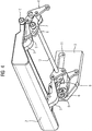
Figur 4 geht hervor, dass das zuvor anhand derFiguren 1 bis 3 erläuterte Getriebe zweifach vorgesehen ist, und zwar jeweils an einer Seite der Tischauszugsplatte 2. Dabei sind zum Synchronisieren der Bewegungen der Getriebe die ersten Hebel 4 mittels einer torsionssteifen Koppelstange 12 miteinander verbunden. Alternativ könnten auch die Lenker 9 in ihrer Bewegung miteinander gekoppelt sein.
Claims (10)
- Fahrgasttisch mit einer ortsfesten Tischplatte (1) und einer Tischauszugsplatte (2), die mittels eines Getriebes aus einer zurückgezogenen Position unterhalb der Tischplatte (1) in eine Gebrauchsposition, bei der sich die Tischauszugsplatte (2) an eine zugeordnete äußere Kante der Tischplatte (1) anschließt, überführbar ist,
dadurch gekennzeichnet, dass
das Getriebe als unterhalb der Tischplatte (1) angeordnetes lineares Kurvengetriebe ausgebildet ist, bei dem eine erste Kurvenrolle (7) auf einer gegenüber der Tischplatte (1) ortfesten ersten Führungsbahn (8) abrollt, und eine Bewegung des linearen Kurvengetriebes über einen ebenen Pantographen-Mechanismus, der einen einen gegenüber der Tischplatte (1) ortsfesten ersten Koppelpunkt (4.4) und einen mit der Tischauszugsplatte (2) drehbar verbundenen zweiten Koppelpunkt (5.2) aufweist, derart skaliert ist, dass der zweite Koppelpunkt (5.2) an der Tischauszugsplatte (2) beim Verbringen der Tischauszugsplatte (2) aus der zurückgezogenen Position in die Gebrauchsposition oder umgekehrt eine längere Bahnkurve im Raum zurücklegt als die erste Kurvenrolle (7) . - Fahrgasttisch nach Anspruch 1,
dadurch gekennzeichnet, dass
der Pantographen-Mechanismus aufweist:- einen ersten Hebel (4), der an dem ersten Koppelpunkt (4.1) drehbar gelagert ist,- einen zweiten Hebel (5), der mit dem ersten Hebel (4) um eine dritte Achse (4.3) drehbar verbunden ist und an seinem, der Tischauszugsplatte (2) zugewandten Ende den zweiten Koppelpunkt (5.2) trägt, und entweder- einen Rollenträger (6), der um eine zweite Achse (4.2) mit dem ersten Hebel (4) drehbar verbunden ist und an dem die Kurvenrolle (10) um eine vierte Achse (7.1) drehbar gelagert ist, und- einen Lenker (9), der mit dem Rollenträger (6) um eine fünfte Achse (9.1) und mit dem zweiten Hebel (5) um eine sechste Achse (9.2) drehbar verbunden ist, oder- einen Lenker (9), der um eine zweite Achse (4.2) mit dem ersten Hebel (4) drehbar verbunden ist, und- einen Rollenträger (6), der mit dem Lenker (9) um eine fünfte Achse (9.1) drehbar verbunden ist, mit dem zweiten Hebel (5) um eine sechste Achse (9.2) drehbar verbunden ist und an dem die Kurvenrolle (10) um eine vierte Achse (7.1) drehbar gelagert ist. - Fahrgasttisch nach Anspruch 1 oder 2,
dadurch gekennzeichnet, dass
die zweite (4.2), dritte (4.3), fünfte (9.1) und sechste Achse (9.2) wenigstens annähernd die Form eines Parallelogramms ausbilden. - Fahrgasttisch nach einem der Ansprüche 1 bis 3,
dadurch gekennzeichnet, dass
der Abstand der zweiten Achse (4.2) von der ersten Achse (4.1) geringer als der Abstand der dritten Achse (4.3) von der ersten Achse (4.1) ist. - Fahrgasttisch nach einem der Ansprüche 1 bis 4,
dadurch gekennzeichnet, dass
der Abstand der vierten Achse (7.1) von der zweiten Achse (4.3) geringer als der Abstand der siebten Achse (5.1) von der dritten Achse (4.2) ist. - Fahrgasttisch nach einem der Ansprüche 1 bis 5,
dadurch gekennzeichnet, dass
zur Definition einer rotatorischen Lage des Tischauszugsplatte (2) um den zweiten Koppelpunkt (5.2) ein weiteres Getriebe vorgesehen ist. - Fahrgasttisch nach Anspruch 6,
dadurch gekennzeichnet, dass
das weitere Getriebe eine an der Tischauszugsplatte (2) gelagerte zweite Kurvenrolle (10) aufweist, die auf einer gegenüber der Tischplatte (1) ortsfesten zweiten Führungsbahn (11) abrollt. - Fahrgasttisch nach Anspruch 7,
dadurch gekennzeichnet, dass
an der Tischplatte (1) ein Grundkörper (3) befestigt ist, in dem die erste und die zweite Führungsbahn (8; 11) jeweils als Nut ausgebildet ist und der eine Lagerung für die erste Achse (4.1) aufweist. - Fahrgasttisch nach einem der Ansprüche 1 bis 8,
dadurch gekennzeichnet, dass
die erste Achse (4.1), die vierte Achse (7.1) und eine siebte Achse (5.1) des zweiten Koppelpunktes (5.2), um die die Tischauszugsplatte (2) gegenüber dem zweiten Hebel (5) drehbar ist, annähernd in einer Ebene angeordnet sind. - Fahrgasttisch nach einem der Ansprüche 1 bis 9,
dadurch gekennzeichnet, dass
die vierte (7.1) und die fünfte Achse (9.1) an dem Rollenträger (6) zusammenfallen.
Applications Claiming Priority (1)
| Application Number | Priority Date | Filing Date | Title |
|---|---|---|---|
| DE102020204408.2A DE102020204408A1 (de) | 2020-04-06 | 2020-04-06 | Fahrgasttisch |
Publications (2)
| Publication Number | Publication Date |
|---|---|
| EP3892494A1 true EP3892494A1 (de) | 2021-10-13 |
| EP3892494B1 EP3892494B1 (de) | 2022-12-14 |
Family
ID=74859307
Family Applications (1)
| Application Number | Title | Priority Date | Filing Date |
|---|---|---|---|
| EP21160964.9A Active EP3892494B1 (de) | 2020-04-06 | 2021-03-05 | Fahrgasttisch |
Country Status (3)
| Country | Link |
|---|---|
| EP (1) | EP3892494B1 (de) |
| DE (1) | DE102020204408A1 (de) |
| ES (1) | ES2940454T3 (de) |
Cited By (1)
| Publication number | Priority date | Publication date | Assignee | Title |
|---|---|---|---|---|
| CN121084441A (zh) * | 2025-09-16 | 2025-12-09 | 沪强企业(盐城)有限公司 | 一种轨道交通用多功能小桌板 |
Citations (3)
| Publication number | Priority date | Publication date | Assignee | Title |
|---|---|---|---|---|
| DE10031700A1 (de) * | 2000-06-29 | 2002-01-17 | Daimler Chrysler Ag | Klapptischanordnung für Fahrzeuge |
| DE102009022625A1 (de) * | 2009-05-27 | 2009-12-31 | Daimler Ag | Klapptischeinrichtung für ein Kraftfahrzeug |
| DE102015204705A1 (de) | 2015-03-16 | 2016-09-22 | Siemens Aktiengesellschaft | Verbreiterbarer Tisch |
Family Cites Families (3)
| Publication number | Priority date | Publication date | Assignee | Title |
|---|---|---|---|---|
| ITUD20030049A1 (it) | 2003-03-03 | 2004-09-04 | Publio Eusebi | Tavolo a configurazione variabile. |
| EP2215926A1 (de) | 2009-02-05 | 2010-08-11 | Internitalia Design Srl | Ausziehtisch, insbesondere für einen Eisenbahn Personenwagen |
| AT513777B1 (de) | 2012-12-17 | 2014-09-15 | Team 7 Natürlich Wohnen GmbH | Möbelbeschlag |
-
2020
- 2020-04-06 DE DE102020204408.2A patent/DE102020204408A1/de not_active Ceased
-
2021
- 2021-03-05 ES ES21160964T patent/ES2940454T3/es active Active
- 2021-03-05 EP EP21160964.9A patent/EP3892494B1/de active Active
Patent Citations (3)
| Publication number | Priority date | Publication date | Assignee | Title |
|---|---|---|---|---|
| DE10031700A1 (de) * | 2000-06-29 | 2002-01-17 | Daimler Chrysler Ag | Klapptischanordnung für Fahrzeuge |
| DE102009022625A1 (de) * | 2009-05-27 | 2009-12-31 | Daimler Ag | Klapptischeinrichtung für ein Kraftfahrzeug |
| DE102015204705A1 (de) | 2015-03-16 | 2016-09-22 | Siemens Aktiengesellschaft | Verbreiterbarer Tisch |
Cited By (1)
| Publication number | Priority date | Publication date | Assignee | Title |
|---|---|---|---|---|
| CN121084441A (zh) * | 2025-09-16 | 2025-12-09 | 沪强企业(盐城)有限公司 | 一种轨道交通用多功能小桌板 |
Also Published As
| Publication number | Publication date |
|---|---|
| DE102020204408A1 (de) | 2021-10-07 |
| ES2940454T3 (es) | 2023-05-08 |
| EP3892494B1 (de) | 2022-12-14 |
Similar Documents
| Publication | Publication Date | Title |
|---|---|---|
| DE102015218025B4 (de) | Aufzugsystem | |
| DE69924774T2 (de) | Zweisitzige, für die Nutzung in der ersten und zweiten Klasse umwandelbare Bank und Verfahren zur Umwandlung einer solchen Bank | |
| DE10206300B4 (de) | Längseinsteller für einen Fahrzeugsitz | |
| DE3411281C2 (de) | ||
| DE69205625T2 (de) | Sitzgleitvorrichtung. | |
| DE20212774U1 (de) | Bahngesteuerter Fensterheber, sowie Mitnehmer und Führungsplatte des bahngesteuerten Fensterhebers | |
| EP3752694A1 (de) | Autoparkvorrichtung | |
| DE102010017329A1 (de) | Längsführung für einen Kraftfahrzeugsitz | |
| DE69518785T2 (de) | Führungsrolleneinheit | |
| EP3892494B1 (de) | Fahrgasttisch | |
| EP3866992B1 (de) | Vorrichtung und verfahren zum flexiblen rollformen eines halbzeugs | |
| EP4086173B1 (de) | Befestigungsvorrichtung zur lösbaren verbindung mit einer lochschiene eines flugzeugs und montageverfahren | |
| DE102011085177B4 (de) | Antriebssystem für ein KFZ-Dachsystem | |
| EP2887513A2 (de) | Linearmotoranordnung und Werkzeugmaschine mit einer Linearmotoranordnung | |
| EP1531290B1 (de) | Schalteinrichtung | |
| DE102017213361B4 (de) | Wälzfräsmaschine, umfassend einen Wälzfrässchlitten und einen Anfasschlitten auf einem gemeinsamen Schienensystem | |
| EP3861240B1 (de) | Abdeckvorrichtung für eine maschinenkabine | |
| DE102004057714A1 (de) | Linearführungssystem mit Stellelementen | |
| DE112022003418B4 (de) | Gleitblock-baugruppe mit kugelbuchsenlager | |
| EP0779174A2 (de) | Sitzlängsverstellung | |
| DE68923174T2 (de) | Anordnung für fahrzeugsitze. | |
| DE102008058242A1 (de) | Schiebetüranordnung | |
| WO2008049407A2 (de) | Deckelanhebekulisse zur steuerung einer zweiphasigen anhebebewegung eines deckels | |
| EP3924285B1 (de) | Aufzugsystem | |
| EP3892513B1 (de) | Fahrgasttisch |
Legal Events
| Date | Code | Title | Description |
|---|---|---|---|
| PUAI | Public reference made under article 153(3) epc to a published international application that has entered the european phase |
Free format text: ORIGINAL CODE: 0009012 |
|
| STAA | Information on the status of an ep patent application or granted ep patent |
Free format text: STATUS: THE APPLICATION HAS BEEN PUBLISHED |
|
| AK | Designated contracting states |
Kind code of ref document: A1 Designated state(s): AL AT BE BG CH CY CZ DE DK EE ES FI FR GB GR HR HU IE IS IT LI LT LU LV MC MK MT NL NO PL PT RO RS SE SI SK SM TR |
|
| STAA | Information on the status of an ep patent application or granted ep patent |
Free format text: STATUS: REQUEST FOR EXAMINATION WAS MADE |
|
| 17P | Request for examination filed |
Effective date: 20220318 |
|
| RBV | Designated contracting states (corrected) |
Designated state(s): AL AT BE BG CH CY CZ DE DK EE ES FI FR GB GR HR HU IE IS IT LI LT LU LV MC MK MT NL NO PL PT RO RS SE SI SK SM TR |
|
| REG | Reference to a national code |
Ref country code: DE Ref legal event code: R079 Ref document number: 502021000309 Country of ref document: DE Free format text: PREVIOUS MAIN CLASS: B60N0003000000 Ipc: B61D0037000000 |
|
| GRAP | Despatch of communication of intention to grant a patent |
Free format text: ORIGINAL CODE: EPIDOSNIGR1 |
|
| STAA | Information on the status of an ep patent application or granted ep patent |
Free format text: STATUS: GRANT OF PATENT IS INTENDED |
|
| RIC1 | Information provided on ipc code assigned before grant |
Ipc: B60N 3/00 20060101ALI20220711BHEP Ipc: B61D 37/00 20060101AFI20220711BHEP |
|
| INTG | Intention to grant announced |
Effective date: 20220811 |
|
| GRAS | Grant fee paid |
Free format text: ORIGINAL CODE: EPIDOSNIGR3 |
|
| GRAA | (expected) grant |
Free format text: ORIGINAL CODE: 0009210 |
|
| STAA | Information on the status of an ep patent application or granted ep patent |
Free format text: STATUS: THE PATENT HAS BEEN GRANTED |
|
| AK | Designated contracting states |
Kind code of ref document: B1 Designated state(s): AL AT BE BG CH CY CZ DE DK EE ES FI FR GB GR HR HU IE IS IT LI LT LU LV MC MK MT NL NO PL PT RO RS SE SI SK SM TR |
|
| REG | Reference to a national code |
Ref country code: GB Ref legal event code: FG4D Free format text: NOT ENGLISH |
|
| REG | Reference to a national code |
Ref country code: CH Ref legal event code: EP |
|
| REG | Reference to a national code |
Ref country code: DE Ref legal event code: R096 Ref document number: 502021000309 Country of ref document: DE |
|
| REG | Reference to a national code |
Ref country code: IE Ref legal event code: FG4D Free format text: LANGUAGE OF EP DOCUMENT: GERMAN |
|
| REG | Reference to a national code |
Ref country code: AT Ref legal event code: REF Ref document number: 1537516 Country of ref document: AT Kind code of ref document: T Effective date: 20230115 |
|
| REG | Reference to a national code |
Ref country code: LT Ref legal event code: MG9D |
|
| REG | Reference to a national code |
Ref country code: NL Ref legal event code: MP Effective date: 20221214 |
|
| PG25 | Lapsed in a contracting state [announced via postgrant information from national office to epo] |
Ref country code: SE Free format text: LAPSE BECAUSE OF FAILURE TO SUBMIT A TRANSLATION OF THE DESCRIPTION OR TO PAY THE FEE WITHIN THE PRESCRIBED TIME-LIMIT Effective date: 20221214 Ref country code: NO Free format text: LAPSE BECAUSE OF FAILURE TO SUBMIT A TRANSLATION OF THE DESCRIPTION OR TO PAY THE FEE WITHIN THE PRESCRIBED TIME-LIMIT Effective date: 20230314 Ref country code: LT Free format text: LAPSE BECAUSE OF FAILURE TO SUBMIT A TRANSLATION OF THE DESCRIPTION OR TO PAY THE FEE WITHIN THE PRESCRIBED TIME-LIMIT Effective date: 20221214 Ref country code: FI Free format text: LAPSE BECAUSE OF FAILURE TO SUBMIT A TRANSLATION OF THE DESCRIPTION OR TO PAY THE FEE WITHIN THE PRESCRIBED TIME-LIMIT Effective date: 20221214 |
|
| REG | Reference to a national code |
Ref country code: ES Ref legal event code: FG2A Ref document number: 2940454 Country of ref document: ES Kind code of ref document: T3 Effective date: 20230508 |
|
| PG25 | Lapsed in a contracting state [announced via postgrant information from national office to epo] |
Ref country code: RS Free format text: LAPSE BECAUSE OF FAILURE TO SUBMIT A TRANSLATION OF THE DESCRIPTION OR TO PAY THE FEE WITHIN THE PRESCRIBED TIME-LIMIT Effective date: 20221214 Ref country code: LV Free format text: LAPSE BECAUSE OF FAILURE TO SUBMIT A TRANSLATION OF THE DESCRIPTION OR TO PAY THE FEE WITHIN THE PRESCRIBED TIME-LIMIT Effective date: 20221214 Ref country code: HR Free format text: LAPSE BECAUSE OF FAILURE TO SUBMIT A TRANSLATION OF THE DESCRIPTION OR TO PAY THE FEE WITHIN THE PRESCRIBED TIME-LIMIT Effective date: 20221214 Ref country code: GR Free format text: LAPSE BECAUSE OF FAILURE TO SUBMIT A TRANSLATION OF THE DESCRIPTION OR TO PAY THE FEE WITHIN THE PRESCRIBED TIME-LIMIT Effective date: 20230315 |
|
| PG25 | Lapsed in a contracting state [announced via postgrant information from national office to epo] |
Ref country code: NL Free format text: LAPSE BECAUSE OF FAILURE TO SUBMIT A TRANSLATION OF THE DESCRIPTION OR TO PAY THE FEE WITHIN THE PRESCRIBED TIME-LIMIT Effective date: 20221214 |
|
| PG25 | Lapsed in a contracting state [announced via postgrant information from national office to epo] |
Ref country code: SM Free format text: LAPSE BECAUSE OF FAILURE TO SUBMIT A TRANSLATION OF THE DESCRIPTION OR TO PAY THE FEE WITHIN THE PRESCRIBED TIME-LIMIT Effective date: 20221214 Ref country code: RO Free format text: LAPSE BECAUSE OF FAILURE TO SUBMIT A TRANSLATION OF THE DESCRIPTION OR TO PAY THE FEE WITHIN THE PRESCRIBED TIME-LIMIT Effective date: 20221214 Ref country code: PT Free format text: LAPSE BECAUSE OF FAILURE TO SUBMIT A TRANSLATION OF THE DESCRIPTION OR TO PAY THE FEE WITHIN THE PRESCRIBED TIME-LIMIT Effective date: 20230414 Ref country code: EE Free format text: LAPSE BECAUSE OF FAILURE TO SUBMIT A TRANSLATION OF THE DESCRIPTION OR TO PAY THE FEE WITHIN THE PRESCRIBED TIME-LIMIT Effective date: 20221214 Ref country code: CZ Free format text: LAPSE BECAUSE OF FAILURE TO SUBMIT A TRANSLATION OF THE DESCRIPTION OR TO PAY THE FEE WITHIN THE PRESCRIBED TIME-LIMIT Effective date: 20221214 |
|
| PGFP | Annual fee paid to national office [announced via postgrant information from national office to epo] |
Ref country code: ES Payment date: 20230621 Year of fee payment: 3 Ref country code: DE Payment date: 20230519 Year of fee payment: 3 |
|
| PG25 | Lapsed in a contracting state [announced via postgrant information from national office to epo] |
Ref country code: SK Free format text: LAPSE BECAUSE OF FAILURE TO SUBMIT A TRANSLATION OF THE DESCRIPTION OR TO PAY THE FEE WITHIN THE PRESCRIBED TIME-LIMIT Effective date: 20221214 Ref country code: PL Free format text: LAPSE BECAUSE OF FAILURE TO SUBMIT A TRANSLATION OF THE DESCRIPTION OR TO PAY THE FEE WITHIN THE PRESCRIBED TIME-LIMIT Effective date: 20221214 Ref country code: IS Free format text: LAPSE BECAUSE OF FAILURE TO SUBMIT A TRANSLATION OF THE DESCRIPTION OR TO PAY THE FEE WITHIN THE PRESCRIBED TIME-LIMIT Effective date: 20230414 Ref country code: AL Free format text: LAPSE BECAUSE OF FAILURE TO SUBMIT A TRANSLATION OF THE DESCRIPTION OR TO PAY THE FEE WITHIN THE PRESCRIBED TIME-LIMIT Effective date: 20221214 |
|
| REG | Reference to a national code |
Ref country code: DE Ref legal event code: R097 Ref document number: 502021000309 Country of ref document: DE |
|
| PLBE | No opposition filed within time limit |
Free format text: ORIGINAL CODE: 0009261 |
|
| STAA | Information on the status of an ep patent application or granted ep patent |
Free format text: STATUS: NO OPPOSITION FILED WITHIN TIME LIMIT |
|
| PG25 | Lapsed in a contracting state [announced via postgrant information from national office to epo] |
Ref country code: MC Free format text: LAPSE BECAUSE OF FAILURE TO SUBMIT A TRANSLATION OF THE DESCRIPTION OR TO PAY THE FEE WITHIN THE PRESCRIBED TIME-LIMIT Effective date: 20221214 Ref country code: DK Free format text: LAPSE BECAUSE OF FAILURE TO SUBMIT A TRANSLATION OF THE DESCRIPTION OR TO PAY THE FEE WITHIN THE PRESCRIBED TIME-LIMIT Effective date: 20221214 |
|
| 26N | No opposition filed |
Effective date: 20230915 |
|
| PG25 | Lapsed in a contracting state [announced via postgrant information from national office to epo] |
Ref country code: SI Free format text: LAPSE BECAUSE OF FAILURE TO SUBMIT A TRANSLATION OF THE DESCRIPTION OR TO PAY THE FEE WITHIN THE PRESCRIBED TIME-LIMIT Effective date: 20221214 |
|
| REG | Reference to a national code |
Ref country code: BE Ref legal event code: MM Effective date: 20230331 |
|
| PG25 | Lapsed in a contracting state [announced via postgrant information from national office to epo] |
Ref country code: LU Free format text: LAPSE BECAUSE OF NON-PAYMENT OF DUE FEES Effective date: 20230305 |
|
| REG | Reference to a national code |
Ref country code: IE Ref legal event code: MM4A |
|
| PG25 | Lapsed in a contracting state [announced via postgrant information from national office to epo] |
Ref country code: IE Free format text: LAPSE BECAUSE OF NON-PAYMENT OF DUE FEES Effective date: 20230305 |
|
| PG25 | Lapsed in a contracting state [announced via postgrant information from national office to epo] |
Ref country code: BE Free format text: LAPSE BECAUSE OF NON-PAYMENT OF DUE FEES Effective date: 20230331 |
|
| PGFP | Annual fee paid to national office [announced via postgrant information from national office to epo] |
Ref country code: FR Payment date: 20240319 Year of fee payment: 4 |
|
| PGFP | Annual fee paid to national office [announced via postgrant information from national office to epo] |
Ref country code: IT Payment date: 20240401 Year of fee payment: 4 |
|
| REG | Reference to a national code |
Ref country code: DE Ref legal event code: R119 Ref document number: 502021000309 Country of ref document: DE |
|
| REG | Reference to a national code |
Ref country code: CH Ref legal event code: PL |
|
| PG25 | Lapsed in a contracting state [announced via postgrant information from national office to epo] |
Ref country code: BG Free format text: LAPSE BECAUSE OF FAILURE TO SUBMIT A TRANSLATION OF THE DESCRIPTION OR TO PAY THE FEE WITHIN THE PRESCRIBED TIME-LIMIT Effective date: 20221214 |
|
| PG25 | Lapsed in a contracting state [announced via postgrant information from national office to epo] |
Ref country code: BG Free format text: LAPSE BECAUSE OF FAILURE TO SUBMIT A TRANSLATION OF THE DESCRIPTION OR TO PAY THE FEE WITHIN THE PRESCRIBED TIME-LIMIT Effective date: 20221214 |
|
| PG25 | Lapsed in a contracting state [announced via postgrant information from national office to epo] |
Ref country code: DE Free format text: LAPSE BECAUSE OF NON-PAYMENT OF DUE FEES Effective date: 20241001 |
|
| PG25 | Lapsed in a contracting state [announced via postgrant information from national office to epo] |
Ref country code: DE Free format text: LAPSE BECAUSE OF NON-PAYMENT OF DUE FEES Effective date: 20241001 Ref country code: CH Free format text: LAPSE BECAUSE OF NON-PAYMENT OF DUE FEES Effective date: 20240331 |
|
| PGFP | Annual fee paid to national office [announced via postgrant information from national office to epo] |
Ref country code: AT Payment date: 20250417 Year of fee payment: 5 |
|
| REG | Reference to a national code |
Ref country code: ES Ref legal event code: FD2A Effective date: 20250425 |
|
| PG25 | Lapsed in a contracting state [announced via postgrant information from national office to epo] |
Ref country code: ES Free format text: LAPSE BECAUSE OF NON-PAYMENT OF DUE FEES Effective date: 20240306 |
|
| PG25 | Lapsed in a contracting state [announced via postgrant information from national office to epo] |
Ref country code: CY Free format text: LAPSE BECAUSE OF FAILURE TO SUBMIT A TRANSLATION OF THE DESCRIPTION OR TO PAY THE FEE WITHIN THE PRESCRIBED TIME-LIMIT; INVALID AB INITIO Effective date: 20210305 |
|
| PG25 | Lapsed in a contracting state [announced via postgrant information from national office to epo] |
Ref country code: HU Free format text: LAPSE BECAUSE OF FAILURE TO SUBMIT A TRANSLATION OF THE DESCRIPTION OR TO PAY THE FEE WITHIN THE PRESCRIBED TIME-LIMIT; INVALID AB INITIO Effective date: 20210305 |
|
| GBPC | Gb: european patent ceased through non-payment of renewal fee |
Effective date: 20250305 |
|
| PG25 | Lapsed in a contracting state [announced via postgrant information from national office to epo] |
Ref country code: TR Free format text: LAPSE BECAUSE OF FAILURE TO SUBMIT A TRANSLATION OF THE DESCRIPTION OR TO PAY THE FEE WITHIN THE PRESCRIBED TIME-LIMIT Effective date: 20221214 |
|
| PG25 | Lapsed in a contracting state [announced via postgrant information from national office to epo] |
Ref country code: GB Free format text: LAPSE BECAUSE OF NON-PAYMENT OF DUE FEES Effective date: 20250305 |
|
| PG25 | Lapsed in a contracting state [announced via postgrant information from national office to epo] |
Ref country code: FR Free format text: LAPSE BECAUSE OF NON-PAYMENT OF DUE FEES Effective date: 20250331 Ref country code: IT Free format text: LAPSE BECAUSE OF NON-PAYMENT OF DUE FEES Effective date: 20250305 |