EP3892448A1 - Fügeverfahren und baugruppe für ein luftfahrzeug - Google Patents
Fügeverfahren und baugruppe für ein luftfahrzeug Download PDFInfo
- Publication number
- EP3892448A1 EP3892448A1 EP21166527.8A EP21166527A EP3892448A1 EP 3892448 A1 EP3892448 A1 EP 3892448A1 EP 21166527 A EP21166527 A EP 21166527A EP 3892448 A1 EP3892448 A1 EP 3892448A1
- Authority
- EP
- European Patent Office
- Prior art keywords
- area
- spatial
- component
- polymer material
- joining method
- Prior art date
- Legal status (The legal status is an assumption and is not a legal conclusion. Google has not performed a legal analysis and makes no representation as to the accuracy of the status listed.)
- Pending
Links
Images



Classifications
-
- B—PERFORMING OPERATIONS; TRANSPORTING
- B29—WORKING OF PLASTICS; WORKING OF SUBSTANCES IN A PLASTIC STATE IN GENERAL
- B29C—SHAPING OR JOINING OF PLASTICS; SHAPING OF MATERIAL IN A PLASTIC STATE, NOT OTHERWISE PROVIDED FOR; AFTER-TREATMENT OF THE SHAPED PRODUCTS, e.g. REPAIRING
- B29C66/00—General aspects of processes or apparatus for joining preformed parts
- B29C66/70—General aspects of processes or apparatus for joining preformed parts characterised by the composition, physical properties or the structure of the material of the parts to be joined; Joining with non-plastics material
- B29C66/72—General aspects of processes or apparatus for joining preformed parts characterised by the composition, physical properties or the structure of the material of the parts to be joined; Joining with non-plastics material characterised by the structure of the material of the parts to be joined
- B29C66/721—Fibre-reinforced materials
-
- B—PERFORMING OPERATIONS; TRANSPORTING
- B29—WORKING OF PLASTICS; WORKING OF SUBSTANCES IN A PLASTIC STATE IN GENERAL
- B29C—SHAPING OR JOINING OF PLASTICS; SHAPING OF MATERIAL IN A PLASTIC STATE, NOT OTHERWISE PROVIDED FOR; AFTER-TREATMENT OF THE SHAPED PRODUCTS, e.g. REPAIRING
- B29C65/00—Joining or sealing of preformed parts, e.g. welding of plastics materials; Apparatus therefor
- B29C65/02—Joining or sealing of preformed parts, e.g. welding of plastics materials; Apparatus therefor by heating, with or without pressure
-
- B—PERFORMING OPERATIONS; TRANSPORTING
- B29—WORKING OF PLASTICS; WORKING OF SUBSTANCES IN A PLASTIC STATE IN GENERAL
- B29C—SHAPING OR JOINING OF PLASTICS; SHAPING OF MATERIAL IN A PLASTIC STATE, NOT OTHERWISE PROVIDED FOR; AFTER-TREATMENT OF THE SHAPED PRODUCTS, e.g. REPAIRING
- B29C65/00—Joining or sealing of preformed parts, e.g. welding of plastics materials; Apparatus therefor
- B29C65/48—Joining or sealing of preformed parts, e.g. welding of plastics materials; Apparatus therefor using adhesives, i.e. using supplementary joining material; solvent bonding
- B29C65/4805—Joining or sealing of preformed parts, e.g. welding of plastics materials; Apparatus therefor using adhesives, i.e. using supplementary joining material; solvent bonding characterised by the type of adhesives
- B29C65/481—Non-reactive adhesives, e.g. physically hardening adhesives
- B29C65/4815—Hot melt adhesives, e.g. thermoplastic adhesives
-
- B—PERFORMING OPERATIONS; TRANSPORTING
- B29—WORKING OF PLASTICS; WORKING OF SUBSTANCES IN A PLASTIC STATE IN GENERAL
- B29C—SHAPING OR JOINING OF PLASTICS; SHAPING OF MATERIAL IN A PLASTIC STATE, NOT OTHERWISE PROVIDED FOR; AFTER-TREATMENT OF THE SHAPED PRODUCTS, e.g. REPAIRING
- B29C65/00—Joining or sealing of preformed parts, e.g. welding of plastics materials; Apparatus therefor
- B29C65/48—Joining or sealing of preformed parts, e.g. welding of plastics materials; Apparatus therefor using adhesives, i.e. using supplementary joining material; solvent bonding
- B29C65/4865—Joining or sealing of preformed parts, e.g. welding of plastics materials; Apparatus therefor using adhesives, i.e. using supplementary joining material; solvent bonding containing additives
- B29C65/487—Joining or sealing of preformed parts, e.g. welding of plastics materials; Apparatus therefor using adhesives, i.e. using supplementary joining material; solvent bonding containing additives characterised by their shape, e.g. being fibres or being spherical
- B29C65/4875—Joining or sealing of preformed parts, e.g. welding of plastics materials; Apparatus therefor using adhesives, i.e. using supplementary joining material; solvent bonding containing additives characterised by their shape, e.g. being fibres or being spherical being spherical, e.g. particles or powders
-
- B—PERFORMING OPERATIONS; TRANSPORTING
- B29—WORKING OF PLASTICS; WORKING OF SUBSTANCES IN A PLASTIC STATE IN GENERAL
- B29C—SHAPING OR JOINING OF PLASTICS; SHAPING OF MATERIAL IN A PLASTIC STATE, NOT OTHERWISE PROVIDED FOR; AFTER-TREATMENT OF THE SHAPED PRODUCTS, e.g. REPAIRING
- B29C65/00—Joining or sealing of preformed parts, e.g. welding of plastics materials; Apparatus therefor
- B29C65/48—Joining or sealing of preformed parts, e.g. welding of plastics materials; Apparatus therefor using adhesives, i.e. using supplementary joining material; solvent bonding
- B29C65/4865—Joining or sealing of preformed parts, e.g. welding of plastics materials; Apparatus therefor using adhesives, i.e. using supplementary joining material; solvent bonding containing additives
- B29C65/487—Joining or sealing of preformed parts, e.g. welding of plastics materials; Apparatus therefor using adhesives, i.e. using supplementary joining material; solvent bonding containing additives characterised by their shape, e.g. being fibres or being spherical
- B29C65/488—Joining or sealing of preformed parts, e.g. welding of plastics materials; Apparatus therefor using adhesives, i.e. using supplementary joining material; solvent bonding containing additives characterised by their shape, e.g. being fibres or being spherical being longitudinal, e.g. fibres
-
- B—PERFORMING OPERATIONS; TRANSPORTING
- B29—WORKING OF PLASTICS; WORKING OF SUBSTANCES IN A PLASTIC STATE IN GENERAL
- B29C—SHAPING OR JOINING OF PLASTICS; SHAPING OF MATERIAL IN A PLASTIC STATE, NOT OTHERWISE PROVIDED FOR; AFTER-TREATMENT OF THE SHAPED PRODUCTS, e.g. REPAIRING
- B29C65/00—Joining or sealing of preformed parts, e.g. welding of plastics materials; Apparatus therefor
- B29C65/48—Joining or sealing of preformed parts, e.g. welding of plastics materials; Apparatus therefor using adhesives, i.e. using supplementary joining material; solvent bonding
- B29C65/50—Joining or sealing of preformed parts, e.g. welding of plastics materials; Apparatus therefor using adhesives, i.e. using supplementary joining material; solvent bonding using adhesive tape, e.g. thermoplastic tape; using threads or the like
- B29C65/5007—Joining or sealing of preformed parts, e.g. welding of plastics materials; Apparatus therefor using adhesives, i.e. using supplementary joining material; solvent bonding using adhesive tape, e.g. thermoplastic tape; using threads or the like characterised by the structure of said adhesive tape, threads or the like
- B29C65/5014—Joining or sealing of preformed parts, e.g. welding of plastics materials; Apparatus therefor using adhesives, i.e. using supplementary joining material; solvent bonding using adhesive tape, e.g. thermoplastic tape; using threads or the like characterised by the structure of said adhesive tape, threads or the like being fibre-reinforced
-
- B—PERFORMING OPERATIONS; TRANSPORTING
- B29—WORKING OF PLASTICS; WORKING OF SUBSTANCES IN A PLASTIC STATE IN GENERAL
- B29C—SHAPING OR JOINING OF PLASTICS; SHAPING OF MATERIAL IN A PLASTIC STATE, NOT OTHERWISE PROVIDED FOR; AFTER-TREATMENT OF THE SHAPED PRODUCTS, e.g. REPAIRING
- B29C65/00—Joining or sealing of preformed parts, e.g. welding of plastics materials; Apparatus therefor
- B29C65/48—Joining or sealing of preformed parts, e.g. welding of plastics materials; Apparatus therefor using adhesives, i.e. using supplementary joining material; solvent bonding
- B29C65/50—Joining or sealing of preformed parts, e.g. welding of plastics materials; Apparatus therefor using adhesives, i.e. using supplementary joining material; solvent bonding using adhesive tape, e.g. thermoplastic tape; using threads or the like
- B29C65/5007—Joining or sealing of preformed parts, e.g. welding of plastics materials; Apparatus therefor using adhesives, i.e. using supplementary joining material; solvent bonding using adhesive tape, e.g. thermoplastic tape; using threads or the like characterised by the structure of said adhesive tape, threads or the like
- B29C65/5021—Joining or sealing of preformed parts, e.g. welding of plastics materials; Apparatus therefor using adhesives, i.e. using supplementary joining material; solvent bonding using adhesive tape, e.g. thermoplastic tape; using threads or the like characterised by the structure of said adhesive tape, threads or the like being multi-layered
-
- B—PERFORMING OPERATIONS; TRANSPORTING
- B29—WORKING OF PLASTICS; WORKING OF SUBSTANCES IN A PLASTIC STATE IN GENERAL
- B29C—SHAPING OR JOINING OF PLASTICS; SHAPING OF MATERIAL IN A PLASTIC STATE, NOT OTHERWISE PROVIDED FOR; AFTER-TREATMENT OF THE SHAPED PRODUCTS, e.g. REPAIRING
- B29C65/00—Joining or sealing of preformed parts, e.g. welding of plastics materials; Apparatus therefor
- B29C65/48—Joining or sealing of preformed parts, e.g. welding of plastics materials; Apparatus therefor using adhesives, i.e. using supplementary joining material; solvent bonding
- B29C65/52—Joining or sealing of preformed parts, e.g. welding of plastics materials; Apparatus therefor using adhesives, i.e. using supplementary joining material; solvent bonding characterised by the way of applying the adhesive
-
- B—PERFORMING OPERATIONS; TRANSPORTING
- B29—WORKING OF PLASTICS; WORKING OF SUBSTANCES IN A PLASTIC STATE IN GENERAL
- B29C—SHAPING OR JOINING OF PLASTICS; SHAPING OF MATERIAL IN A PLASTIC STATE, NOT OTHERWISE PROVIDED FOR; AFTER-TREATMENT OF THE SHAPED PRODUCTS, e.g. REPAIRING
- B29C65/00—Joining or sealing of preformed parts, e.g. welding of plastics materials; Apparatus therefor
- B29C65/48—Joining or sealing of preformed parts, e.g. welding of plastics materials; Apparatus therefor using adhesives, i.e. using supplementary joining material; solvent bonding
- B29C65/52—Joining or sealing of preformed parts, e.g. welding of plastics materials; Apparatus therefor using adhesives, i.e. using supplementary joining material; solvent bonding characterised by the way of applying the adhesive
- B29C65/524—Joining or sealing of preformed parts, e.g. welding of plastics materials; Apparatus therefor using adhesives, i.e. using supplementary joining material; solvent bonding characterised by the way of applying the adhesive by applying the adhesive from an outlet device in contact with, or almost in contact with, the surface of the part to be joined
-
- B—PERFORMING OPERATIONS; TRANSPORTING
- B29—WORKING OF PLASTICS; WORKING OF SUBSTANCES IN A PLASTIC STATE IN GENERAL
- B29C—SHAPING OR JOINING OF PLASTICS; SHAPING OF MATERIAL IN A PLASTIC STATE, NOT OTHERWISE PROVIDED FOR; AFTER-TREATMENT OF THE SHAPED PRODUCTS, e.g. REPAIRING
- B29C65/00—Joining or sealing of preformed parts, e.g. welding of plastics materials; Apparatus therefor
- B29C65/48—Joining or sealing of preformed parts, e.g. welding of plastics materials; Apparatus therefor using adhesives, i.e. using supplementary joining material; solvent bonding
- B29C65/52—Joining or sealing of preformed parts, e.g. welding of plastics materials; Apparatus therefor using adhesives, i.e. using supplementary joining material; solvent bonding characterised by the way of applying the adhesive
- B29C65/526—Joining or sealing of preformed parts, e.g. welding of plastics materials; Apparatus therefor using adhesives, i.e. using supplementary joining material; solvent bonding characterised by the way of applying the adhesive by printing or by transfer from the surfaces of elements carrying the adhesive, e.g. using brushes, pads, rollers, stencils or silk screens
-
- B—PERFORMING OPERATIONS; TRANSPORTING
- B29—WORKING OF PLASTICS; WORKING OF SUBSTANCES IN A PLASTIC STATE IN GENERAL
- B29C—SHAPING OR JOINING OF PLASTICS; SHAPING OF MATERIAL IN A PLASTIC STATE, NOT OTHERWISE PROVIDED FOR; AFTER-TREATMENT OF THE SHAPED PRODUCTS, e.g. REPAIRING
- B29C66/00—General aspects of processes or apparatus for joining preformed parts
- B29C66/01—General aspects dealing with the joint area or with the area to be joined
- B29C66/02—Preparation of the material, in the area to be joined, prior to joining or welding
- B29C66/022—Mechanical pre-treatments, e.g. reshaping
- B29C66/0222—Mechanical pre-treatments, e.g. reshaping without removal of material, e.g. cleaning by air blowing or using brushes
-
- B—PERFORMING OPERATIONS; TRANSPORTING
- B29—WORKING OF PLASTICS; WORKING OF SUBSTANCES IN A PLASTIC STATE IN GENERAL
- B29C—SHAPING OR JOINING OF PLASTICS; SHAPING OF MATERIAL IN A PLASTIC STATE, NOT OTHERWISE PROVIDED FOR; AFTER-TREATMENT OF THE SHAPED PRODUCTS, e.g. REPAIRING
- B29C66/00—General aspects of processes or apparatus for joining preformed parts
- B29C66/01—General aspects dealing with the joint area or with the area to be joined
- B29C66/05—Particular design of joint configurations
- B29C66/10—Particular design of joint configurations particular design of the joint cross-sections
- B29C66/11—Joint cross-sections comprising a single joint-segment, i.e. one of the parts to be joined comprising a single joint-segment in the joint cross-section
- B29C66/112—Single lapped joints
- B29C66/1122—Single lap to lap joints, i.e. overlap joints
-
- B—PERFORMING OPERATIONS; TRANSPORTING
- B29—WORKING OF PLASTICS; WORKING OF SUBSTANCES IN A PLASTIC STATE IN GENERAL
- B29C—SHAPING OR JOINING OF PLASTICS; SHAPING OF MATERIAL IN A PLASTIC STATE, NOT OTHERWISE PROVIDED FOR; AFTER-TREATMENT OF THE SHAPED PRODUCTS, e.g. REPAIRING
- B29C66/00—General aspects of processes or apparatus for joining preformed parts
- B29C66/01—General aspects dealing with the joint area or with the area to be joined
- B29C66/05—Particular design of joint configurations
- B29C66/303—Particular design of joint configurations the joint involving an anchoring effect
- B29C66/3032—Particular design of joint configurations the joint involving an anchoring effect making use of protrusions or cavities belonging to at least one of the parts to be joined
- B29C66/30321—Particular design of joint configurations the joint involving an anchoring effect making use of protrusions or cavities belonging to at least one of the parts to be joined making use of protrusions belonging to at least one of the parts to be joined
- B29C66/30322—Particular design of joint configurations the joint involving an anchoring effect making use of protrusions or cavities belonging to at least one of the parts to be joined making use of protrusions belonging to at least one of the parts to be joined in the form of rugosity
-
- B—PERFORMING OPERATIONS; TRANSPORTING
- B29—WORKING OF PLASTICS; WORKING OF SUBSTANCES IN A PLASTIC STATE IN GENERAL
- B29C—SHAPING OR JOINING OF PLASTICS; SHAPING OF MATERIAL IN A PLASTIC STATE, NOT OTHERWISE PROVIDED FOR; AFTER-TREATMENT OF THE SHAPED PRODUCTS, e.g. REPAIRING
- B29C66/00—General aspects of processes or apparatus for joining preformed parts
- B29C66/01—General aspects dealing with the joint area or with the area to be joined
- B29C66/341—Measures for intermixing the material of the joint interlayer
-
- B—PERFORMING OPERATIONS; TRANSPORTING
- B29—WORKING OF PLASTICS; WORKING OF SUBSTANCES IN A PLASTIC STATE IN GENERAL
- B29C—SHAPING OR JOINING OF PLASTICS; SHAPING OF MATERIAL IN A PLASTIC STATE, NOT OTHERWISE PROVIDED FOR; AFTER-TREATMENT OF THE SHAPED PRODUCTS, e.g. REPAIRING
- B29C66/00—General aspects of processes or apparatus for joining preformed parts
- B29C66/40—General aspects of joining substantially flat articles, e.g. plates, sheets or web-like materials; Making flat seams in tubular or hollow articles; Joining single elements to substantially flat surfaces
- B29C66/41—Joining substantially flat articles ; Making flat seams in tubular or hollow articles
- B29C66/43—Joining a relatively small portion of the surface of said articles
-
- B—PERFORMING OPERATIONS; TRANSPORTING
- B29—WORKING OF PLASTICS; WORKING OF SUBSTANCES IN A PLASTIC STATE IN GENERAL
- B29C—SHAPING OR JOINING OF PLASTICS; SHAPING OF MATERIAL IN A PLASTIC STATE, NOT OTHERWISE PROVIDED FOR; AFTER-TREATMENT OF THE SHAPED PRODUCTS, e.g. REPAIRING
- B29C66/00—General aspects of processes or apparatus for joining preformed parts
- B29C66/70—General aspects of processes or apparatus for joining preformed parts characterised by the composition, physical properties or the structure of the material of the parts to be joined; Joining with non-plastics material
- B29C66/71—General aspects of processes or apparatus for joining preformed parts characterised by the composition, physical properties or the structure of the material of the parts to be joined; Joining with non-plastics material characterised by the composition of the plastics material of the parts to be joined
-
- B—PERFORMING OPERATIONS; TRANSPORTING
- B29—WORKING OF PLASTICS; WORKING OF SUBSTANCES IN A PLASTIC STATE IN GENERAL
- B29C—SHAPING OR JOINING OF PLASTICS; SHAPING OF MATERIAL IN A PLASTIC STATE, NOT OTHERWISE PROVIDED FOR; AFTER-TREATMENT OF THE SHAPED PRODUCTS, e.g. REPAIRING
- B29C66/00—General aspects of processes or apparatus for joining preformed parts
- B29C66/70—General aspects of processes or apparatus for joining preformed parts characterised by the composition, physical properties or the structure of the material of the parts to be joined; Joining with non-plastics material
- B29C66/71—General aspects of processes or apparatus for joining preformed parts characterised by the composition, physical properties or the structure of the material of the parts to be joined; Joining with non-plastics material characterised by the composition of the plastics material of the parts to be joined
- B29C66/712—General aspects of processes or apparatus for joining preformed parts characterised by the composition, physical properties or the structure of the material of the parts to be joined; Joining with non-plastics material characterised by the composition of the plastics material of the parts to be joined the composition of one of the parts to be joined being different from the composition of the other part
-
- B—PERFORMING OPERATIONS; TRANSPORTING
- B29—WORKING OF PLASTICS; WORKING OF SUBSTANCES IN A PLASTIC STATE IN GENERAL
- B29C—SHAPING OR JOINING OF PLASTICS; SHAPING OF MATERIAL IN A PLASTIC STATE, NOT OTHERWISE PROVIDED FOR; AFTER-TREATMENT OF THE SHAPED PRODUCTS, e.g. REPAIRING
- B29C66/00—General aspects of processes or apparatus for joining preformed parts
- B29C66/70—General aspects of processes or apparatus for joining preformed parts characterised by the composition, physical properties or the structure of the material of the parts to be joined; Joining with non-plastics material
- B29C66/72—General aspects of processes or apparatus for joining preformed parts characterised by the composition, physical properties or the structure of the material of the parts to be joined; Joining with non-plastics material characterised by the structure of the material of the parts to be joined
- B29C66/721—Fibre-reinforced materials
- B29C66/7214—Fibre-reinforced materials characterised by the length of the fibres
- B29C66/72141—Fibres of continuous length
-
- B—PERFORMING OPERATIONS; TRANSPORTING
- B29—WORKING OF PLASTICS; WORKING OF SUBSTANCES IN A PLASTIC STATE IN GENERAL
- B29C—SHAPING OR JOINING OF PLASTICS; SHAPING OF MATERIAL IN A PLASTIC STATE, NOT OTHERWISE PROVIDED FOR; AFTER-TREATMENT OF THE SHAPED PRODUCTS, e.g. REPAIRING
- B29C66/00—General aspects of processes or apparatus for joining preformed parts
- B29C66/70—General aspects of processes or apparatus for joining preformed parts characterised by the composition, physical properties or the structure of the material of the parts to be joined; Joining with non-plastics material
- B29C66/73—General aspects of processes or apparatus for joining preformed parts characterised by the composition, physical properties or the structure of the material of the parts to be joined; Joining with non-plastics material characterised by the intensive physical properties of the material of the parts to be joined, by the optical properties of the material of the parts to be joined, by the extensive physical properties of the parts to be joined, by the state of the material of the parts to be joined or by the material of the parts to be joined being a thermoplastic or a thermoset
- B29C66/731—General aspects of processes or apparatus for joining preformed parts characterised by the composition, physical properties or the structure of the material of the parts to be joined; Joining with non-plastics material characterised by the intensive physical properties of the material of the parts to be joined, by the optical properties of the material of the parts to be joined, by the extensive physical properties of the parts to be joined, by the state of the material of the parts to be joined or by the material of the parts to be joined being a thermoplastic or a thermoset characterised by the intensive physical properties of the material of the parts to be joined
- B29C66/7311—Thermal properties
- B29C66/73115—Melting point
- B29C66/73116—Melting point of different melting point, i.e. the melting point of one of the parts to be joined being different from the melting point of the other part
-
- B—PERFORMING OPERATIONS; TRANSPORTING
- B29—WORKING OF PLASTICS; WORKING OF SUBSTANCES IN A PLASTIC STATE IN GENERAL
- B29C—SHAPING OR JOINING OF PLASTICS; SHAPING OF MATERIAL IN A PLASTIC STATE, NOT OTHERWISE PROVIDED FOR; AFTER-TREATMENT OF THE SHAPED PRODUCTS, e.g. REPAIRING
- B29C66/00—General aspects of processes or apparatus for joining preformed parts
- B29C66/70—General aspects of processes or apparatus for joining preformed parts characterised by the composition, physical properties or the structure of the material of the parts to be joined; Joining with non-plastics material
- B29C66/73—General aspects of processes or apparatus for joining preformed parts characterised by the composition, physical properties or the structure of the material of the parts to be joined; Joining with non-plastics material characterised by the intensive physical properties of the material of the parts to be joined, by the optical properties of the material of the parts to be joined, by the extensive physical properties of the parts to be joined, by the state of the material of the parts to be joined or by the material of the parts to be joined being a thermoplastic or a thermoset
- B29C66/737—General aspects of processes or apparatus for joining preformed parts characterised by the composition, physical properties or the structure of the material of the parts to be joined; Joining with non-plastics material characterised by the intensive physical properties of the material of the parts to be joined, by the optical properties of the material of the parts to be joined, by the extensive physical properties of the parts to be joined, by the state of the material of the parts to be joined or by the material of the parts to be joined being a thermoplastic or a thermoset characterised by the state of the material of the parts to be joined
- B29C66/7375—General aspects of processes or apparatus for joining preformed parts characterised by the composition, physical properties or the structure of the material of the parts to be joined; Joining with non-plastics material characterised by the intensive physical properties of the material of the parts to be joined, by the optical properties of the material of the parts to be joined, by the extensive physical properties of the parts to be joined, by the state of the material of the parts to be joined or by the material of the parts to be joined being a thermoplastic or a thermoset characterised by the state of the material of the parts to be joined uncured, partially cured or fully cured
- B29C66/73751—General aspects of processes or apparatus for joining preformed parts characterised by the composition, physical properties or the structure of the material of the parts to be joined; Joining with non-plastics material characterised by the intensive physical properties of the material of the parts to be joined, by the optical properties of the material of the parts to be joined, by the extensive physical properties of the parts to be joined, by the state of the material of the parts to be joined or by the material of the parts to be joined being a thermoplastic or a thermoset characterised by the state of the material of the parts to be joined uncured, partially cured or fully cured the to-be-joined area of at least one of the parts to be joined being uncured, i.e. non cross-linked, non vulcanized
-
- B—PERFORMING OPERATIONS; TRANSPORTING
- B29—WORKING OF PLASTICS; WORKING OF SUBSTANCES IN A PLASTIC STATE IN GENERAL
- B29C—SHAPING OR JOINING OF PLASTICS; SHAPING OF MATERIAL IN A PLASTIC STATE, NOT OTHERWISE PROVIDED FOR; AFTER-TREATMENT OF THE SHAPED PRODUCTS, e.g. REPAIRING
- B29C66/00—General aspects of processes or apparatus for joining preformed parts
- B29C66/70—General aspects of processes or apparatus for joining preformed parts characterised by the composition, physical properties or the structure of the material of the parts to be joined; Joining with non-plastics material
- B29C66/73—General aspects of processes or apparatus for joining preformed parts characterised by the composition, physical properties or the structure of the material of the parts to be joined; Joining with non-plastics material characterised by the intensive physical properties of the material of the parts to be joined, by the optical properties of the material of the parts to be joined, by the extensive physical properties of the parts to be joined, by the state of the material of the parts to be joined or by the material of the parts to be joined being a thermoplastic or a thermoset
- B29C66/739—General aspects of processes or apparatus for joining preformed parts characterised by the composition, physical properties or the structure of the material of the parts to be joined; Joining with non-plastics material characterised by the intensive physical properties of the material of the parts to be joined, by the optical properties of the material of the parts to be joined, by the extensive physical properties of the parts to be joined, by the state of the material of the parts to be joined or by the material of the parts to be joined being a thermoplastic or a thermoset characterised by the material of the parts to be joined being a thermoplastic or a thermoset
- B29C66/7392—General aspects of processes or apparatus for joining preformed parts characterised by the composition, physical properties or the structure of the material of the parts to be joined; Joining with non-plastics material characterised by the intensive physical properties of the material of the parts to be joined, by the optical properties of the material of the parts to be joined, by the extensive physical properties of the parts to be joined, by the state of the material of the parts to be joined or by the material of the parts to be joined being a thermoplastic or a thermoset characterised by the material of the parts to be joined being a thermoplastic or a thermoset characterised by the material of at least one of the parts being a thermoplastic
-
- B—PERFORMING OPERATIONS; TRANSPORTING
- B29—WORKING OF PLASTICS; WORKING OF SUBSTANCES IN A PLASTIC STATE IN GENERAL
- B29C—SHAPING OR JOINING OF PLASTICS; SHAPING OF MATERIAL IN A PLASTIC STATE, NOT OTHERWISE PROVIDED FOR; AFTER-TREATMENT OF THE SHAPED PRODUCTS, e.g. REPAIRING
- B29C66/00—General aspects of processes or apparatus for joining preformed parts
- B29C66/70—General aspects of processes or apparatus for joining preformed parts characterised by the composition, physical properties or the structure of the material of the parts to be joined; Joining with non-plastics material
- B29C66/73—General aspects of processes or apparatus for joining preformed parts characterised by the composition, physical properties or the structure of the material of the parts to be joined; Joining with non-plastics material characterised by the intensive physical properties of the material of the parts to be joined, by the optical properties of the material of the parts to be joined, by the extensive physical properties of the parts to be joined, by the state of the material of the parts to be joined or by the material of the parts to be joined being a thermoplastic or a thermoset
- B29C66/739—General aspects of processes or apparatus for joining preformed parts characterised by the composition, physical properties or the structure of the material of the parts to be joined; Joining with non-plastics material characterised by the intensive physical properties of the material of the parts to be joined, by the optical properties of the material of the parts to be joined, by the extensive physical properties of the parts to be joined, by the state of the material of the parts to be joined or by the material of the parts to be joined being a thermoplastic or a thermoset characterised by the material of the parts to be joined being a thermoplastic or a thermoset
- B29C66/7394—General aspects of processes or apparatus for joining preformed parts characterised by the composition, physical properties or the structure of the material of the parts to be joined; Joining with non-plastics material characterised by the intensive physical properties of the material of the parts to be joined, by the optical properties of the material of the parts to be joined, by the extensive physical properties of the parts to be joined, by the state of the material of the parts to be joined or by the material of the parts to be joined being a thermoplastic or a thermoset characterised by the material of the parts to be joined being a thermoplastic or a thermoset characterised by the material of at least one of the parts being a thermoset
-
- B—PERFORMING OPERATIONS; TRANSPORTING
- B29—WORKING OF PLASTICS; WORKING OF SUBSTANCES IN A PLASTIC STATE IN GENERAL
- B29C—SHAPING OR JOINING OF PLASTICS; SHAPING OF MATERIAL IN A PLASTIC STATE, NOT OTHERWISE PROVIDED FOR; AFTER-TREATMENT OF THE SHAPED PRODUCTS, e.g. REPAIRING
- B29C66/00—General aspects of processes or apparatus for joining preformed parts
- B29C66/70—General aspects of processes or apparatus for joining preformed parts characterised by the composition, physical properties or the structure of the material of the parts to be joined; Joining with non-plastics material
- B29C66/73—General aspects of processes or apparatus for joining preformed parts characterised by the composition, physical properties or the structure of the material of the parts to be joined; Joining with non-plastics material characterised by the intensive physical properties of the material of the parts to be joined, by the optical properties of the material of the parts to be joined, by the extensive physical properties of the parts to be joined, by the state of the material of the parts to be joined or by the material of the parts to be joined being a thermoplastic or a thermoset
- B29C66/739—General aspects of processes or apparatus for joining preformed parts characterised by the composition, physical properties or the structure of the material of the parts to be joined; Joining with non-plastics material characterised by the intensive physical properties of the material of the parts to be joined, by the optical properties of the material of the parts to be joined, by the extensive physical properties of the parts to be joined, by the state of the material of the parts to be joined or by the material of the parts to be joined being a thermoplastic or a thermoset characterised by the material of the parts to be joined being a thermoplastic or a thermoset
- B29C66/7394—General aspects of processes or apparatus for joining preformed parts characterised by the composition, physical properties or the structure of the material of the parts to be joined; Joining with non-plastics material characterised by the intensive physical properties of the material of the parts to be joined, by the optical properties of the material of the parts to be joined, by the extensive physical properties of the parts to be joined, by the state of the material of the parts to be joined or by the material of the parts to be joined being a thermoplastic or a thermoset characterised by the material of the parts to be joined being a thermoplastic or a thermoset characterised by the material of at least one of the parts being a thermoset
- B29C66/73941—General aspects of processes or apparatus for joining preformed parts characterised by the composition, physical properties or the structure of the material of the parts to be joined; Joining with non-plastics material characterised by the intensive physical properties of the material of the parts to be joined, by the optical properties of the material of the parts to be joined, by the extensive physical properties of the parts to be joined, by the state of the material of the parts to be joined or by the material of the parts to be joined being a thermoplastic or a thermoset characterised by the material of the parts to be joined being a thermoplastic or a thermoset characterised by the material of at least one of the parts being a thermoset characterised by the materials of both parts being thermosets
-
- B—PERFORMING OPERATIONS; TRANSPORTING
- B33—ADDITIVE MANUFACTURING TECHNOLOGY
- B33Y—ADDITIVE MANUFACTURING, i.e. MANUFACTURING OF THREE-DIMENSIONAL [3D] OBJECTS BY ADDITIVE DEPOSITION, ADDITIVE AGGLOMERATION OR ADDITIVE LAYERING, e.g. BY 3D PRINTING, STEREOLITHOGRAPHY OR SELECTIVE LASER SINTERING
- B33Y80/00—Products made by additive manufacturing
-
- B—PERFORMING OPERATIONS; TRANSPORTING
- B29—WORKING OF PLASTICS; WORKING OF SUBSTANCES IN A PLASTIC STATE IN GENERAL
- B29C—SHAPING OR JOINING OF PLASTICS; SHAPING OF MATERIAL IN A PLASTIC STATE, NOT OTHERWISE PROVIDED FOR; AFTER-TREATMENT OF THE SHAPED PRODUCTS, e.g. REPAIRING
- B29C65/00—Joining or sealing of preformed parts, e.g. welding of plastics materials; Apparatus therefor
- B29C65/002—Joining methods not otherwise provided for
- B29C65/006—Diffusion joining
-
- B—PERFORMING OPERATIONS; TRANSPORTING
- B29—WORKING OF PLASTICS; WORKING OF SUBSTANCES IN A PLASTIC STATE IN GENERAL
- B29C—SHAPING OR JOINING OF PLASTICS; SHAPING OF MATERIAL IN A PLASTIC STATE, NOT OTHERWISE PROVIDED FOR; AFTER-TREATMENT OF THE SHAPED PRODUCTS, e.g. REPAIRING
- B29C66/00—General aspects of processes or apparatus for joining preformed parts
- B29C66/01—General aspects dealing with the joint area or with the area to be joined
- B29C66/05—Particular design of joint configurations
- B29C66/303—Particular design of joint configurations the joint involving an anchoring effect
- B29C66/3032—Particular design of joint configurations the joint involving an anchoring effect making use of protrusions or cavities belonging to at least one of the parts to be joined
- B29C66/30321—Particular design of joint configurations the joint involving an anchoring effect making use of protrusions or cavities belonging to at least one of the parts to be joined making use of protrusions belonging to at least one of the parts to be joined
-
- B—PERFORMING OPERATIONS; TRANSPORTING
- B29—WORKING OF PLASTICS; WORKING OF SUBSTANCES IN A PLASTIC STATE IN GENERAL
- B29C—SHAPING OR JOINING OF PLASTICS; SHAPING OF MATERIAL IN A PLASTIC STATE, NOT OTHERWISE PROVIDED FOR; AFTER-TREATMENT OF THE SHAPED PRODUCTS, e.g. REPAIRING
- B29C66/00—General aspects of processes or apparatus for joining preformed parts
- B29C66/01—General aspects dealing with the joint area or with the area to be joined
- B29C66/05—Particular design of joint configurations
- B29C66/303—Particular design of joint configurations the joint involving an anchoring effect
- B29C66/3032—Particular design of joint configurations the joint involving an anchoring effect making use of protrusions or cavities belonging to at least one of the parts to be joined
- B29C66/30325—Particular design of joint configurations the joint involving an anchoring effect making use of protrusions or cavities belonging to at least one of the parts to be joined making use of cavities belonging to at least one of the parts to be joined
-
- B—PERFORMING OPERATIONS; TRANSPORTING
- B29—WORKING OF PLASTICS; WORKING OF SUBSTANCES IN A PLASTIC STATE IN GENERAL
- B29L—INDEXING SCHEME ASSOCIATED WITH SUBCLASS B29C, RELATING TO PARTICULAR ARTICLES
- B29L2031/00—Other particular articles
- B29L2031/30—Vehicles, e.g. ships or aircraft, or body parts thereof
- B29L2031/3076—Aircrafts
Definitions
- the invention relates to a joining method for joining a, preferably fiber-reinforced, first component to a fiber-reinforced, second component.
- the invention also relates to an assembly for an aircraft.
- Fiber-reinforced components are used in aviation because of their many advantages. Conventional joining processes such as riveting, gluing, welding and interdiffusion joining can be used to produce larger assemblies.
- An example of film-based interdiffusion joining (FIDJ) is from EP 3 124 208 A1 known.
- the invention is based on the object of improving connections between fiber-reinforced components, preferably with regard to the load properties in the inhomogeneous load case.
- connection area is formed with a first spatial area and a second spatial area.
- the first spatial area consists of the first polymer material and the second spatial area consists of a thermoplastic polymer material different from the first polymer material.
- the first spatial area contains short fibers and / or continuous fibers. It is preferred that the second spatial area contains short fibers and / or continuous fibers.
- first spatial area and the second spatial area are formed adjacent in a planar layer of the connection area that is parallel to the joining area. It is preferred that the first spatial area and the second spatial area are formed adjacent in a thickness direction of the connection area running normal to the joining surface.
- connection area is formed with a plurality of first and second spatial areas. It is preferred that, viewed in a thickness direction running normal to the joining surface, the extension of the first spatial regions gradually decreases with increasing distance from the first component, while the extension of the second spatial regions gradually increases. It is preferable that the first and second space areas are arranged alternately in the thickness direction. It is preferred that the first and second spatial areas form a cellular structure and / or a wave-shaped structure. It is preferred that the first and second spatial areas are designed and arranged in such a way that there is a gradual transition in the direction of thickness from the first polymer material to the polymer material or to the polymer materials which the connecting area contains.
- the majority of the fibers in the first spatial region run in a first direction and the majority of the fibers in the second spatial region run in a second direction which is different from, preferably orthogonal to, the first direction.
- a spatial area is formed as a core area of the connection area, the core area being arranged in such a way that the core area only covers the components and adjacent spatial areas.
- the first spatial area and / or the second spatial area is preferably a core area.
- the core area consists of a, preferably fiber-reinforced, thermoplastic polymer material.
- a spatial area is formed as an outer edge area of the connection area, the outer edge area being arranged such that the outer edge area extends along a circumference of the connection area and only covers the components and the core area.
- the first spatial area and / or the second spatial area is preferably an outer edge area.
- the outer edge area consists of a, preferably unreinforced, thermoplastic polymer material. It it is preferred that the outer edge area has a lower melting temperature than the material of the core area.
- a spatial area is formed as an intermediate area of the connecting area, the intermediate area being arranged between the outer edge area and the core area.
- the first spatial area and / or the second spatial area is preferably the intermediate area.
- the intermediate area consists of a, preferably unreinforced, thermoplastic polymer material. It is preferred that the polymer material is identical to the polymer material of the core region. It is preferred that the polymer material is different from the polymer material of the outer edge region. It is preferred that the polymer material has a higher melting temperature than the material of the outer edge region.
- step ba) the surface structure area is formed on a side of the connection area facing away from the joining area. It is preferred that in step ba) the surface structure area is formed in a plane parallel to the joining surface with elevations and depressions, which are preferably designed in a wave-like manner, and / or a corrugated or serrated pattern. It is preferred that in step ba) the surface structure region is formed in such a way that a form fit is formed between the connection region and the first component in a plane parallel to the joining surface.
- the first polymer material is a thermoplastic polymer material or a thermosetting polymer material. It is preferred that the second polymer material is a thermoset polymer material. It is preferred that the connection area contains a polymer material which preferably has a lower melting temperature than the first polymer material.
- step a) and step ba) take place by means of additive manufacturing. It is preferred that step a) and step ba) by means of additive manufacturing take place in such a way that first the connection area is manufactured and then the first component is manufactured.
- the invention also creates an assembly, preferably for an aircraft, obtainable by using a previously described joining method.
- One idea is to join components made of composite materials that have different matrix systems.
- Typical components in the field of aviation are, for example, brackets, clips, fastening eyes, stringers, frames, skins and the like.
- weight, approval, manufacturing effort, manufacturing repeatability, damage tolerance, load capacity and the like must be taken into account.
- M 2 IDJ Multi-Material Interdiffusion Joining
- FLM filament layer manufacturing
- M 2 IDJ can either be applied to conventional film geometry or to join 3D-printed thermoplastic components with thermoset components.
- thermoplastics are high performance thermoplastics, e.g. B. Polyaryletherketones (PAEK), such as polyetheretherketone (PEEK) and polyetherketoneketone (PEKK).
- PAEK Polyaryletherketones
- PEEK polyetheretherketone
- PEKK polyetherketoneketone
- Thermoplastics with a lower melting temperature include polyetherimides (PEI), blends made of PEI and polycarbonate (PC), thermoplastic polyurethane (TPU) and polyamides.
- Typical thermoset systems are epoxy resins.
- the thermoplastics can preferably contain filler material, for example particles or fibers (both short fibers and continuous fibers).
- connection to shear, peeling, tearing, splitting and the like can be done in different ways.
- inhomogeneous joint loads such as shearing, peeling, splitting
- the relevant module can be adjusted.
- additives eg fibers, particles
- the fibers can run in different preferred directions. It is also conceivable to use a preferably structured multi-matrix.
- edge enhancement in which, for example, the fiber orientation is adapted in an edge area of the connection area, only the pure matrix or a tougher matrix is applied.
- Another measure can be to apply locally tough particles / lines / patterns with the aim of bridging cracks. Furthermore, pores can be created or poorly connected fibers to pin cracks. The pores can also act as crack stoppers. Another idea is to provide a tough matrix locally with a connection to the main matrix in order to deflect the crack path.
- a preferred embodiment can contain microparticles or other additives - for example rubber particles or TPU - in order to distribute and thereby reduce shear forces.
- Another embodiment can contain high-modulus additives, such as graphite, carbon nanotubes or carbon black, to prevent microcracks.
- Another idea is to provide highly viscous local phases made of thermoplastic with a melting temperature below the infusion temperature for the purpose of binding to textile parts or preforms. Furthermore, a perforation can be provided in the connection area as an infusion aid.
- a transition phase or a transition area can be formed in the connection area in order to connect alien polymers.
- the transition has a gradual cellular geometry.
- Crossovers between different material phases are also possible.
- PEI can first be printed out as the connection area and then PEEK for the actual component. The two materials can fuse locally due to the higher melting temperature of the PEEK.
- connection area with a surface structure by means of which the connection area is connected to the component, while the joining surface remains smooth.
- the surface structure can advantageously be produced by means of additive manufacturing.
- the assembly 10 comprises a first component 12 and a second component 14, which are connected to one another via a connection region 16.
- the assembly 10 is intended for an aircraft, for example.
- the first component 12 can be a reinforcement component such as a stringer.
- the second component 14 can be a fuselage component, for example an outer skin, which is intended to be reinforced by the first component 12.
- the first component 12 is a fiber-reinforced component that contains a matrix made of a first polymer material 18.
- the first polymer material 18 is selected from the group of polyaryletherketones, for example PEEK.
- the second component 14 is a fiber-reinforced component that contains a matrix made of a thermoset second polymer material 20.
- the second polymer material 20 is, for example, epoxy resin.
- the connecting area 16 consists of a thermoplastic polymer material, for example PEI.
- the connection area 16 can be designed as a film or as a foil.
- the first component 12 and the connection region 16 are fused to one another at a melt layer 22. This can be achieved, for example, in that the first component 12 is manufactured additively on the connection area 16.
- the connecting area 16 also has a joining surface 24, which is preferably opposite the melting layer 22.
- the second component 14 is arranged with an area in contact with the joining surface 24. In this state, the second polymer material 20 is still in the curable state. Heat is then supplied in order to heat the first polymer material 18 above its glass transition temperature and to activate the curing of the second polymer material 20. This creates an interdiffusion layer 26 between the second component 14 and the connection area 16. The connection area 16 is then fixed to the second component 14, so that the first component 12 and the second component 14 have been joined together to form the assembly 10.
- connection area 16 is produced similarly to the first component 12 by additive manufacturing. In the sequence, the connection area 16 is first generated and then the first component 12 is built up on the connection area 16. Then proceed as described above.
- Fig. 3 shows a connection area 16 which is manufactured additively from a fiber-reinforced thermoplastic first polymer material 18, for example fiber-reinforced PEI.
- the fibers are, for example, continuous fibers and can be arranged at an angle of + 45 ° and -45 °.
- the connecting region 16 may contain more than one layer, each with a changing fiber direction from layer to layer. Accordingly, points the connecting area 16 has a first spatial area 28 with a first fiber direction and a second spatial area 30 with a second fiber direction, which can be orthogonal to the first fiber direction. Then proceed as described above.
- the second spatial area 30 is viewed as consisting of a different polymer material compared to the first spatial area 28, because the fibers run in a different direction.
- Fig. 4 shows a connection area 16 which is manufactured additively.
- the connecting area 16 contains a first space area 28 and a second space area 30.
- the first spatial area 28 is designed as an outer edge area 32.
- the outer edge area 32 has an exposed side 33.
- the outer edge area 32 consists, for example, of unreinforced thermoplastic, such as PEI.
- the second spatial area 30 is designed as a core area 34.
- the core area 34 adjoins the outer edge area 32, the first component 12 and the second component 14.
- the core area 34 consists, for example, of fiber-reinforced thermoplastic, such as PEI.
- the core region 34 can have different fiber directions, as described above.
- Fig. 5 shows a connection area 16 which is manufactured additively.
- the connecting area 16 contains a first space area 28 and a second space area 30.
- the first spatial area 28 is designed as an outer edge area 32 and as a core area 34.
- the first spatial area 28 consists, for example, of a fiber-reinforced thermoplastic such as PEI, the fibers running at a 90 ° angle relative to the first component 12 or the second component 14.
- the second spatial area 30 is designed as an intermediate area 36 which is arranged between the outer edge area 32 and the core area 34.
- the second spatial area 30 consists, for example, of a fiber-reinforced thermoplastic such as PEI.
- the fibers run at a 0 ° angle.
- the second spatial area 30 is viewed as consisting of a different polymer material compared to the first spatial area 28, because the fibers run in a different direction.
- Fig. 6 shows a connection area 16 which is manufactured additively.
- the connecting area 16 contains a first space area 28, a second space area 30, a third space area 38 and a fourth space area 40.
- the first spatial area 28 is designed as an outer edge area 32.
- the outer edge region 32 consists of an unreinforced thermoplastic polymer material, for example polyamide or thermoplastic polyurethane, the polymer material having a low melting temperature.
- the second spatial area 30 is designed as an intermediate area 36.
- the intermediate area 36 consists of an unreinforced thermoplastic polymer material such as PEI.
- the intermediate region 36 has a higher melting temperature than the outer edge region 32.
- the third spatial area 38 is designed as a further intermediate area 42, which is arranged between the intermediate area 36 and the core area 34.
- the further intermediate area 42 consists of a fiber-reinforced thermoplastic polymer material such as PEI, in which the fibers run at a 90 ° angle.
- the fourth spatial area 40 is designed as a core area 34.
- the core area 34 consists of a fiber-reinforced thermoplastic polymer material such as PEI, in which the fibers run at a 0 ° angle.
- Fig. 7 shows a connection area 16 which is manufactured additively.
- the connection area 16 is formed with a surface structure area 44 on which the melt layer 22 is formed.
- the surface structure region 44 is structured in such a way that a form fit is generated in a plane parallel to the joining surface 24.
- the surface structure region 44 can have periodically changing elevations 46 and depressions 48.
- the surface structure region 44 can be configured to be wave-shaped, with a groove or serrated pattern and / or the like.
- Fig. 8 shows a connection area 16 which is manufactured additively.
- the connection area 16 is formed in such a way that in the thickness direction D there is a gradual transition between the polymer material of the connection area 16 and the first polymer material 18.
- a plurality of polymer layers 50 are produced, the proportion of polymer lines from the first polymer material 18 increasing layer by layer.
- the first spatial area 28 and the second spatial area 30 are created by the different polymer lines.
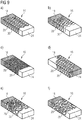
- Fig. 9 shows further examples of such a system of polymer layers 50 with the first spatial area 28 and the second spatial area 30.
- the transition can be designed as a cellular structure or periodically alternating area, as shown in FIG Fig. 9 are shown.
- connection area 16 is provided.
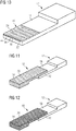
- the provision can take place in that the first component 12 and the connection area 16 are manufactured additively.
- the connection area 16 is preferably produced first or at the same time as the first component 12.
- the connection area 16 is formed in any one or a meaningful combination of the examples described above.
- the second component 14 in the uncured state is brought into contact with a region with the joining surface 24.
- the second component 14 can be a textile preform, a carbon fiber reinforced plastic part or the like. If necessary, the second component 14 is infused in this position.
- FIG. 12 the assembly 10 completed by adding heat.
- the first component 12 is then joined to the second component 14 to form the assembly 10, which is shown in FIG Fig. 13 is shown schematically.
- thermoplastic connecting area 16 is formed on the thermoplastic component 12.
- the connection area 16 is connected to the thermoset component 14 by means of interdiffusion.
- the still uncured second component 14 is brought into contact with the connection area 16 and heat is supplied.
- An interdiffusion layer 26 is created, which firmly connects the second component 14 and the connecting region 16 to one another and thus joins the first component 12 with the second component 14.
Landscapes
- Engineering & Computer Science (AREA)
- Mechanical Engineering (AREA)
- Chemical & Material Sciences (AREA)
- Manufacturing & Machinery (AREA)
- Materials Engineering (AREA)
- Physics & Mathematics (AREA)
- Thermal Sciences (AREA)
- Lining Or Joining Of Plastics Or The Like (AREA)
- Laminated Bodies (AREA)
Abstract
Description
- Die Erfindung betrifft ein Fügeverfahren zum Fügen eines, vorzugsweise faserverstärkten, ersten Bauteils mit einem faserverstärkten, zweiten Bauteil. Ferner betrifft die Erfindung eine Baugruppe für ein Luftfahrzeug.
- Faserverstärkte Bauteile kommen aufgrund vielfältiger Vorzüge in der Luftfahrt zum Einsatz. Um größerer Baugruppen herzustellen können übliche Fügeverfahren, wie etwa Nieten, Kleben, Schweißen und Interdiffusionsfügen verwendet werden. Ein Beispiel für filmbasiertes Interdiffusionsfügen (engl. film interdiffusion joining, FIDJ) ist aus
EP 3 124 208 A1 bekannt. - Einige der bekannten Verfahren können einen hohen Fertigungsaufwand verursachen. Des Weiteren sind nicht alle Verfahren für jede Art von Materialpaarung geeignet. Insbesondere kann es wünschenswert sein, die Verbindung an die gewünschte Funktion der zu verbindenden Bauteile anzupassen, was üblicherweise über die Geometrie und die Materialeigenschaften der Bauteile eingestellt wird. Dies kann bei Klebeverbindungen und Schweißverbindungen schwierig sein.
- Der Erfindung liegt die Aufgabe zugrunde Verbindungen zwischen faserverstärkten Bauteilen zu verbessern, vorzugsweise hinsichtlich der Lasteigenschaften im inhomogenen Lastfall.
- Die Aufgabe wird durch den Gegenstand der unabhängigen Ansprüche gelöst. Bevorzugte Weiterbildungen sind Gegenstand der abhängigen Ansprüche.
- Die Erfindung schafft ein Fügeverfahren zum Fügen eines, vorzugsweise faserverstärkten, ersten Bauteils, das ein erstes Polymermaterial als Matrix enthält, mit einem, vorzugsweise faserverstärkten, zweiten Bauteil, das ein zweites Polymermaterial als Matrix enthält, wobei das Verfahren umfasst:
- a) Bereitstellen des ersten Bauteils;
- b) Ausbilden eines Verbindungsbereichs auf dem ersten Bauteil, um eine Fügefläche an dem ersten Bauteil zu erzeugen, wobei der Verbindungsbereich aus einem oder mehreren thermoplastischen Polymermaterialen besteht und mit wenigstens einem der folgenden Merkmale ausgebildet wird:
- ba) der Verbindungsbereich wird mit einer Mehrzahl von aneinandergrenzenden Raumbereichen ausgebildet, wobei wenigstens zwei benachbarte Raumbereiche aus unterschiedlichen thermoplastischen Polymermaterialien bestehen; und/oder
- bb) der Verbindungsbereich wird mit einem Oberflächenstrukturbereich ausgebildet, der in wenigstens einer Richtung periodische Erhebungen und Vertiefungen aufweist;
- c) Anordnen eines Bereichs des zweiten Bauteils in Kontakt mit der Fügefläche und Zuführen von Wärme, um den Verbindungsbereich an dem zweiten Bauteil zu fixieren, vorzugsweise unter Bildung einer Interdiffusionsschicht, um das erste Bauteil mit dem zweiten Bauteil zu fügen.
- Es ist bevorzugt, dass in Schritt ba) der Verbindungsbereich mit einem ersten Raumbereich und einem zweiten Raumbereich ausgebildet wird.
- Es ist bevorzugt, dass der erste Raumbereich aus dem ersten Polymermaterial besteht und der zweite Raumbereich aus einem von dem ersten Polymermaterial verschiedenen thermoplastischen Polymermaterial besteht.
- Es ist bevorzugt, dass der erste Raumbereich Kurzfasern und/oder Endlosfasern enthält. Es ist bevorzugt, dass der zweite Raumbereich Kurzfasern und/oder Endlosfasern enthält.
- Es ist bevorzugt, dass der erste Raumbereich und der zweite Raumbereich in einer zur Fügefläche parallelen flächigen Schicht des Verbindungsbereichs benachbart ausgebildet werden. Es ist bevorzugt, dass der erste Raumbereich und der zweite Raumbereich in einer normal zu der Fügefläche verlaufenden Dickenrichtung des Verbindungsbereichs benachbart ausgebildet werden.
- Es ist bevorzugt, dass in Schritt ba) der Verbindungsbereich mit einer Mehrzahl von ersten und zweiten Raumbereichen ausgebildet wird. Es ist bevorzugt, dass in einer normal zu der Fügefläche verlaufenden Dickenrichtung betrachtet die Ausdehnung der ersten Raumbereiche mit größer werdendem Abstand von dem ersten Bauteil allmählich abnimmt während die Ausdehnung der zweiten Raumbereiche allmählich zunimmt. Es ist bevorzugt, dass die ersten und zweiten Raumbereiche in der Dickenrichtung im Wechsel angeordnet sind. Es ist bevorzugt, dass die ersten und zweiten Raumbereiche eine zellulare Struktur und/oder wellenförmige Struktur bilden. Es ist bevorzugt, dass die ersten und zweiten Raumbereiche derart ausgebildet und angeordnet sind, dass in Dickenrichtung ein allmählicher Übergang von dem ersten Polymermaterial zu dem Polymermaterial beziehungsweise zu den Polymermaterialen erfolgt, die der Verbindungsbereich enthält.
- Es ist bevorzugt, dass die Fasern in dem ersten Raumbereich mehrheitlich in einer ersten Richtung verlaufen und die Fasern in dem zweiten Raumbereich mehrheitlich in einer zweiten Richtung verlaufen, die verschieden von, bevorzugt orthogonal zu, der ersten Richtung ist.
- Es ist bevorzugt, dass in Schritt ba) ein Raumbereich als ein Kernbereich des Verbindungsbereichs ausgebildet wird, wobei der Kernbereich derart angeordnet ist, dass der Kernbereich lediglich die Bauteile und benachbarte Raumbereiche erfasst. Vorzugsweise ist der erste Raumbereich und/oder der zweite Raumbereich ein Kernbereich. Es ist bevorzugt, dass der Kernbereich aus einem, vorzugsweise faserverstärkten, thermoplastischen Polymermaterial besteht.
- Es ist bevorzugt, dass in Schritt ba) ein Raumbereich als ein äußerer Randbereich des Verbindungsbereichs ausgebildet wird, wobei der äußere Randbereich derart angeordnet ist, dass der äußere Randbereich sich entlang eines Umfangs des Verbindungsbereichs erstreckt und lediglich die Bauteile und den Kernbereich erfasst. Vorzugsweise ist der erste Raumbereich und/oder der zweite Raumbereich ein äußerer Randbereich. Es ist bevorzugt, dass der äußere Randbereich aus einem, vorzugsweise unverstärkten, thermoplastischen Polymermaterial besteht. Es ist bevorzugt, dass der äußere Randbereich eine geringere Schmelztemperatur als das Material des Kernbereichs aufweist.
- Es ist bevorzugt, dass in Schritt ba) ein Raumbereich als ein Zwischenbereich des Verbindungsbereichs ausgebildet wird, wobei der Zwischenbereich zwischen dem äußeren Randbereich und dem Kernbereich angeordnet ist. Vorzugsweise ist der erste Raumbereich und/oder der zweite Raumbereich der Zwischenbereich. Es ist bevorzugt, dass der Zwischenbereich aus einem, vorzugsweise unverstärkten, thermoplastischen Polymermaterial besteht. Es ist bevorzugt, dass das Polymermaterial identisch zu dem Polymermaterial des Kernbereichs ist. Es ist bevorzugt, dass das Polymermaterial verschieden von dem Polymermaterial des äußeren Randbereichs ist. Es ist bevorzugt, dass das Polymermaterial eine höhere Schmelztemperatur als das Material des äußeren Randbereichs aufweist.
- Es ist bevorzugt, dass in Schritt ba) der Oberflächenstrukturbereich auf einer der Fügefläche abgewandten Seite des Verbindungsbereichs ausgebildet wird. Es ist bevorzugt, dass in Schritt ba) der Oberflächenstrukturbereich in einer Ebene parallel zu der Fügefläche mit Erhebungen und Vertiefungen, die vorzugsweise wellenförmig gestaltet sind, und/oder einem Riffel- oder Zackenmuster ausgebildet sind. Es ist bevorzugt, dass in Schritt ba) der Oberflächenstrukturberich derart ausgebildet wird, das in einer Ebene parallel zu der Fügefläche ein Formschluss zwischen dem Verbindungsbereich und dem ersten Bauteil gebildet ist.
- Es ist bevorzugt, dass das erste Polymermaterial ein thermoplastisches Polymermaterial oder ein duromeres Polymermaterial ist. Es ist bevorzugt, dass das zweite Polymermaterial ein duromeres Polymermaterial ist. Es ist bevorzugt, dass der Verbindungsbereich ein Polymaterial enthält, das vorzugsweise eine niedrigere Schmelztemperatur als das erste Polymermaterial aufweist.
- Es ist bevorzugt, dass Schritt a) und Schritt ba) mittels additiver Fertigung erfolgen. Es ist bevorzugt, dass Schritt a) und Schritt ba) mittels additiver Fertigung derart erfolgen, dass zunächst der Verbindungsbereich gefertigt wird und anschließend das erste Bauteil gefertigt wird.
- Die Erfindung schafft ferner eine Baugruppe, vorzugsweise für ein Luftfahrzeug, erhältlich durch Anwendung eines zuvor beschriebenen Fügeverfahrens.
- Eine Idee ist es Bauteile aus Verbundwerkstoffen, die unterschiedliche Matrixsysteme aufweisen, miteinander zu fügen. Typische Bauteile im Bereich der Luftfahrt sind etwa Klammern, Clips, Befestigungsösen, Stringer, Spanten, Häute und dergleichen. Wie bei den herkömmlichen Verfahren sind Gewicht, Zulassung, Fertigungsaufwand, Fertigungswiederholbarkeit, Schadenstoleranz, Lastkapazität und dergleichen zu beachten. Diese Aspekte können durch die Erfindung verbessert werden.
- Beispielsweise können sogenannte "kissing bonds" durch Interdiffusionsverbindungen vermieden werden. Zusätzlich kommt bei der Erfindung hinzu, dass die herkömmlichen Verfahren eine homogene Verbindung, etwa durch homogene Materialeigenschaften und -geometrien, an Stellen erzeugen, die allgemein inhomogen belastet sind. So kann die Dehnung in den Substraten zu lokalen Spannungsüberhöhungen in den Randbereichen oder Schällasten durch außermittige Belastung führen.
- Ein Vorschlag ist es, die Interdiffusion von mehreren Materialien zu benutzen, was als Multi-Material Interdiffusion Joining (M2IDJ) bezeichnet werden kann. Diese Art der Verbindung kann vorzugsweise durch additive Fertigung mittels Filamentschichtfertigung (engl. filament layer manufacturing, FLM) erzeugt werden. Die Verbindung erlaubt eine erhöhte Lastkapazität und Schadenstoleranz. Gleichzeitig kann das Strukturgewicht und der Fertigungsaufwand verringert werden.
- Die Verwendung mehrerer Materialen und die überlegenen Fähigkeiten des 3D-Drucks nahezu beliebige Geometrien zu verwirklichen erlaubt es die Struktur der Verbindungsbereiche und Interdiffusionszonen vorab an die erwarteten Lastszenarien anzupassen. M2IDJ kann einerseits auf die herkömmliche Filmgeometrie angewandt werden oder zum Verbinden von 3D-gedruckten thermoplastischen Bauteilen mit duromeren Bauteilen.
- Zur Anpassung können unter anderem folgende Parameter variiert werden:
- Thermoplaste mit unterschiedlicher Löslichkeit in der Duromermatrix
- Thermoplaste mit unterschiedlicher Werkstofffestigkeit und -steifigkeit
- Thermoplaste mit hoher/niedriger Bruchzähigkeit
- Mikroadditive (Partikel) und Makroadditive (Fasern)
- Werkstoffverbindungszonenarchitektur (Werkstoffdesign, Filmdicke, Porosität, Produktionsweg, Neuausrichtung von Additiven)
- Typischerweise verwendete Thermoplaste sind Hochleistungs-Thermoplaste, z. B. Polyaryletherketone (PAEK), wie etwa Polyetheretherketon (PEEK) und Polyetherketonketon (PEKK). Thermoplaste mit niedrigerer Schmelztemperatur sind etwa Polyetherimide (PEI), Blends aus PEI und Polycarbonat (PC), thermoplastisches Polyurethan (TPU) sowie Polyamide. Typische Duromersysteme sind etwa Epoxidharze. Vorzugsweise können die Thermoplaste Füllmaterial enthalten, beispielsweise Partikel oder Fasern (sowohl Kurzfasern als auch Endlosfasern).
- Die Anpassung der Verbindung an Scherung, Schälung, Reißen, Spaltung und dergleichen kann auf unterschiedliche Arten erfolgen. Bei inhomogener Fugenbelastung, wie etwa Scherung, Schälung, Spaltung, kann eine Anpassung des maßgeblichen Moduls erfolgen. So können für derartige Beanspruchungen Additive (z.B. Fasern, Partikel) in das Thermoplast eingebettet werden, um beispielsweise den Schermodul in Richtung der erwarteten Belastung zu vergrößern. Die Fasern können dabei in unterschiedliche Vorzugsrichtungen verlaufen. Denkbar ist auch Verwendung einer vorzugsweise strukturierten Multi-Matrix.
- Eine weitere Anpassungsmöglichkeit ist eine Kantenertüchtigung, bei der beispielsweise in einem Randbereich des Verbindungsbereichs die Faserausrichtung angepasst, lediglich die Reinmatrix oder eine zähere Matrix aufgetragen wird.
- Eine weitere Maßnahme kann es sein, lokal zähe Partikel/Linien/Muster aufzubringen, mit dem Ziel Risse zu überbrücken. Weiters können Poren geschaffen werden oder schlecht angebundene Fasern, um Risse zu pinnen. Die Poren können auch als Rissstopper fungieren. Eine weitere Idee ist es, lokal eine zähe Matrix mit Anbindung an die Hauptmatrix vorzusehen, um den Risspfad abzulenken. Eine bevorzugte Ausgestaltung kann Mikropartikel oder andere Additive enthalten - beispielsweise Gummipartikel oder TPU - um Scherkräfte aufzuteilen und dadurch zu senken. Noch eine Ausgestaltung kann Hochmodulige Additive, wie Graphit, Kohlenstoffnanoröhrchen oder Ruß, zur Verhinderung von Mikrorissen enthalten.
- Eine weitere Idee ist es, hochzähe lokale Phasen aus Thermoplast mit einer Schmelztemperatur unterhalb der Infusionstemperatur zwecks Anbindung an Textile Teile bzw. Preforms vorzusehen. Desweiteren kann eine Perforation in dem Verbindungsbereich vorgesehen sein als Infusionshilfe.
- Zur Anbindung artfremder Polymere kann eine Übergangsphase bzw. ein Übergangsbereich in dem Verbindungsbereich ausgebildet werden. Idealerweise weist der Übergang eine graduelle zellulare Geometrie auf. Auch Überkreuzungen zwischen unterschiedlichen Materialphasen ist möglich. Beispielsweise kann zunächst PEI als Verbindungsbereich ausgedruckt werden und anschließend PEEK für das eigentliche Bauteil. Dabei können die beiden Materialien aufgrund der höheren Schmelztemperatur des PEEK lokal verschmelzen.
- Eine weitere Idee ist es, den Verbindungsbereich mit einer Oberflächenstruktur zu versehen mittels der der Verbindungsbereich an das Bauteil angebunden wird, während die Fügefläche glatt bleibt. Die Oberflächenstruktur kann vorteilhaft mittels additiver Fertigung erzeugt werden.
- Ausführungsbeispiele werden anhand der beigefügten schematischen Zeichnungen näher erläutert. Darin zeigt:
- Fig. 1 bis Fig. 8
- Ausführungsbeispiele einer Baugruppe;
- Fig. 9
- Detailansichten (a) bis (f) unterschiedlicher Beispiele von Verbindungsbereichen; und
- Fig. 10 bis Fig. 13
- ein Ausführungsbeispiel eines Fügeverfahrens.
- Es wird zunächst auf die
Fig. 1 Bezug genommen, die eine Baugruppe 10 zeigt. Die Baugruppe 10 umfasst ein erstes Bauteil 12 und ein zweites Bauteil 14, die über einen Verbindungsbereich 16 miteinander verbunden sind. - Die Baugruppe 10 ist beispielsweise für ein Luftfahrzeug bestimmt. Das erste Bauteil 12 kann ein Verstärkungsbauteil, wie etwa ein Stringer sein. Das zweite Bauteil 14 kann ein Rumpfbauteil sein, etwa eine Außenhaut, die durch das erste Bauteil 12 verstärkt werden soll.
- Das erste Bauteil 12 ist ein faserverstärktes Bauteil, das eine Matrix aus einem ersten Polymermaterial 18 enthält. Das erste Polymermaterial 18 ist ausgewählt aus der Gruppe der Polyaryletherketone, beispielsweise PEEK.
- Das zweite Bauteil 14 ist ein faserverstärktes Bauteil, das eine Matrix aus einem duromeren zweiten Polymermaterial 20 enthält. Das zweite Polymermaterial 20 ist beispielsweise Epoxidharz.
- Der Verbindungsbereich 16 besteht aus einem thermoplastischen Polymermaterial, beispielsweise PEI. Der Verbindungsbereich 16 kann als Film oder als Folie ausgebildet sein.
- Das erste Bauteil 12 und der Verbindungsbereich 16 sind an einer Schmelzschicht 22 miteinander verschmolzen. Dies kann zum Beispiel dadurch erreicht werden, dass das erste Bauteil 12 auf dem Verbindungsbereich 16 additiv gefertigt wird.
- Der Verbindungsbereich 16 hat ferner eine Fügefläche 24, die vorzugsweise der Schmelzschicht 22 gegenüberliegt.
- Das zweite Bauteil 14 wird mit einem Bereich in Kontakt mit der Fügefläche 24 angeordnet. In diesem Zustand ist das zweite Polymermaterial 20 noch im aushärtbaren Zustand. Sodann wird Wärme zugeführt, um das erste Polymermaterial 18 über dessen Glasübergangstemperatur zu erwärmen und das Aushärten des zweiten Polymermaterials 20 zu aktivieren. Dabei entsteht eine Interdiffusionsschicht 26 zwischen dem zweiten Bauteil 14 und dem Verbindungsbereich 16. Der Verbindungsbereich 16 ist dann an dem zweiten Bauteil 14 fixiert, sodass insgesamt das erste Bauteil 12 und das zweite Bauteil 14 zu der Baugruppe 10 gefügt worden sind.
- Die weiteren Ausführungsbeispiele werden lediglich insoweit erläutert, als sie sich von dem zuvor beschriebenen Beispiel unterscheiden.
- Wie in
Fig. 2 angedeutet, wird der Verbindungsbereich 16 ähnlich wie das erste Bauteil 12 durch additive Fertigung erzeugt. In der Reihenfolge wird zunächst der Verbindungsbereich 16 erzeugt und sodann das erste Bauteil 12 auf dem Verbindungsbereich 16 aufgebaut. Anschließend wird wie zuvor beschrieben verfahren. -
Fig. 3 zeigt einen Verbindungsbereich 16, der aus einem faserverstärkten thermoplastischen ersten Polymermaterial 18, beispielsweise faserverstärktes PEI, additiv gefertigt wird. Die Fasern sind beispielsweise Endlosfasern und können im +45° und -45° Winkel angeordnet sein. - Es ist auch möglich, dass der Verbindungsbereich 16 mehr als eine Schicht enthält mit jeweils wechselnder Faserrichtung von Schicht zu Schicht. Demnach weist der Verbindungsbereich 16 einen ersten Raumbereich 28 mit einer ersten Faserrichtung und einen zweiten Raumbereich 30 mit einer zweiten Faserrichtung auf, die zu der ersten Faserrichtung orthogonal sein kann. Anschließend wird wie zuvor beschrieben verfahren.
- Es sollte beachtet werden, dass der zweite Raumbereich 30 im Vergleich zu dem ersten Raumbereich 28 als aus unterschiedlichem Polymermaterial bestehend angesehen wird, weil die Fasern in anderer Richtung verlaufen.
-
Fig. 4 zeigt einen Verbindungsbereich 16, der additiv gefertigt wird. Der Verbindungsbereich 16 enthält einen ersten Raumbereich 28 und einen zweiten Raumbereich 30. - Der erste Raumbereich 28 ist als äußerer Randbereich 32 ausgebildet. Der äußere Randbereich 32 hat eine freiliegenden Seite 33. Der äußere Randbereich 32 besteht beispielsweise aus unverstärktem Thermoplast, wie PEI.
- Der zweite Raumbereich 30 ist als Kernbereich 34 ausgebildet. Der Kernbereich 34 grenzt an den äußeren Randbereich 32, das erste Bauteil 12 sowie das zweite Bauteil 14. Der Kernbereich 34 besteht beispielsweise aus faserverstärktem Thermoplast, wie PEI. Der Kernbereich 34 kann unterschiedliche Faserrichtungen aufweisen, wie zuvor beschrieben.
-
Fig. 5 zeigt einen Verbindungsbereich 16, der additiv gefertigt wird. Der Verbindungsbereich 16 enthält einen ersten Raumbereich 28 und einen zweiten Raumbereich 30. - Der erste Raumbereich 28 ist als äußerer Randbereich 32 und als Kernbereich 34 ausgebildet. Der erste Raumbereich 28 besteht beispielsweise aus einem faserverstärkten Thermoplast wie PEI, wobei die Fasern relativ zu dem ersten Bauteil 12 oder dem zweiten Bauteil 14 im 90°-Winkel verlaufen.
- Der zweite Raumbereich 30 ist als Zwischenbereich 36 ausgebildet, der zwischen dem äußeren Randbereich 32 und dem Kernbereich 34 angeordnet ist. Der zweite Raumbereich 30 besteht beispielsweise aus einem faserverstärkten Thermoplast wie PEI.
- Anders als beim ersten Raumbereich 28 verlaufen die Fasern in einem 0°-Winkel. Es sollte beachtet werden, dass der zweite Raumbereich 30 im Vergleich zu dem ersten Raumbereich 28 als aus unterschiedlichem Polymermaterial bestehend angesehen wird, weil die Fasern in anderer Richtung verlaufen.
-
Fig. 6 zeigt einen Verbindungsbereich 16, der additiv gefertigt wird. Der Verbindungsbereich 16 enthält einen ersten Raumbereich 28, einen zweiten Raumbereich 30, einen dritten Raumbereich 38 und einen vierten Raumbereich 40. - Der erste Raumbereich 28 ist als äußerer Randbereich 32 ausgebildet. Der äußere Randbereich 32 besteht aus einem unverstärkten thermoplastischen Polymermaterial, beispielsweise Polyamid oder thermoplastisches Polyurethan, wobei das Polymermaterial eine niedrige Schmelztemperatur aufweist.
- Der zweite Raumbereich 30 ist als Zwischenbereich 36 ausgebildet. Der Zwischenbereich 36 besteht aus einem unverstärkten thermoplastischen Polymermaterial wie PEI. Der Zwischenbereich 36 weist eine höhere Schmelztemperatur als der äußere Randbereich 32 auf.
- Der dritte Raumbereich 38 ist als weiterer Zwischenbereich 42 ausgebildet, der zwischen dem Zwischenbereich 36 und dem Kernbereich 34 angeordnet ist. Der weitere Zwischenbereich 42 besteht aus einem faserverstärkten thermoplastischen Polymermaterial wie PEI, bei dem die Fasern im 90°-Winkel verlaufen.
- Der vierte Raumbereich 40 ist als Kernbereich 34 ausgebildet. Der Kernbereich 34 besteht aus einem faserverstärkten thermoplastischen Polymermaterial wie PEI, bei dem die Fasern im 0°-Winkel verlaufen.
-
Fig. 7 zeigt einen Verbindungsbereich 16, der additiv gefertigt wird. Der Verbindungsbereich 16 wird mit einem Oberflächenstrukturbereich 44 ausgebildet, auf dem die Schmelzschicht 22 gebildet wird. Der Oberflächenstrukturbereich 44 wird so strukturiert, dass ein Formschluss in einer Ebene parallel zu der Fügefläche 24 erzeugt wird. Der Oberflächenstrukturbereich 44 kann periodisch wechselnde Erhebungen 46 und Vertiefungen 48 aufweisen. Der Oberflächenstrukturbereich 44 kann wellenförmig, mit einem Rillen- oder Zackenmuster und/oder dergleichen ausgebildet werden. -
Fig. 8 zeigt einen Verbindungsbereich 16, der additiv gefertigt wird. Der Verbindungsbereich 16 wird so ausgebildet, dass in Dickenrichtung D ein allmählicher Übergang zwischen dem Polymermaterial des Verbindungsbereichs 16 und dem ersten Polymermaterial 18 erfolgt. Beispielsweise werden eine Mehrzahl von Polymerschichten 50 erzeugt, wobei der Anteil an Polymerlinien aus dem ersten Polymermaterial 18 Schicht für Schicht zunimmt. Durch die verschiedenen Polymerlinien entsteht der erste Raumbereich 28 und der zweite Raumbereich 30. -
Fig. 9 zeigt weitere Beispiele für eine derartiges System aus Polymerschichten 50 mit dem ersten Raumbereich 28 und dem zweiten Raumbereich 30. Der Übergang kann als zellulare Struktur oder periodisch im Wechsel angeordnete Bereich ausgestaltet sein, wie sie inFig. 9 dargestellt sind. - Mit Bezug auf
Fig. 10 bis Fig. 12 wird das Fügeverfahren erläutert. Zunächst wird das erste Bauteil 12 mit dem Verbindungsbereich 16 bereitgestellt. Die Bereitstellung kann dadurch erfolgen, dass das erste Bauteil 12 und der Verbindungsbereich 16 additiv gefertigt werden. Vorzugsweise wird der Verbindungsbereich 16 zuerst gefertigt oder gleichzeitig mit dem ersten Bauteil 12. Der Verbindungsbereich 16 wird in irgendeiner oder einer sinnvollen Kombination der zuvor beschriebenen Beispiele ausgebildet. - Mit Blick auf
Fig. 11 wird das zweite Bauteil 14 in unausgehärtetem Zustand mit einem Bereich mit der Fügefläche 24 in Kontakt gebracht. Das zweite Bauteil 14 kann ein textiles Preform, ein Kohlenstofffaserverstärktes Kunststoffteil oder dergleichen sein. Sofern erforderlich wird das zweite Bauteil 14 in dieser Position infundiert. - Anschließend wird, wie in
Fig. 12 dargestellt, die Baugruppe 10 fertiggestellt durch Zufur von Wärme. Das erste Bauteil 12 ist sodann mit dem zweiten Bauteil 14 zu der Baugruppe 10 gefügt, die inFig. 13 schematisch dargestellt ist. - Zum Verbessern der Charakteristika oder ermöglichen von bislang unmöglichen Verbindungen zwischen thermoplastischen und duromeren Bauteilen 12, 14 wird ein Multi-Material-Fügeverfahren vorgeschlagen, bei dem ein thermoplastischer Verbindungsbereich 16 auf dem thermoplastischen Bauteil 12 ausgebildet wird. Der Verbindungsbereich 16 wird mittels Interdiffusion an das duromere Bauteil 14 angeschlossen. Dafür wird das noch unausgehärtete zweite Bauteil 14 mit dem Verbindungsbereich 16 in Kontakt gebracht und Wärme zugeführt. Es entsteht eine Interdiffusionsschicht 26, die das zweite Bauteil 14 und den Verbindungsbereich 16 fest miteinander verbindet und damit das erste Bauteil 12 mit dem zweiten Bauteil 14 fügt.
-
- 10
- Baugruppe
- 12
- erstes Bauteil
- 14
- zweites Bauteil
- 16
- Verbindungsbereich
- 18
- erstes Polymermaterial
- 20
- zweites Polymermaterial
- 22
- Schmelzschicht
- 24
- Fügefläche
- 26
- Interdiffusionsschicht
- 28
- erster Raumbereich
- 30
- zweiter Raumbereich
- 32
- äußerer Randbereich
- 33
- freiliegende Seite
- 34
- Kernbereich
- 36
- Zwischenbereich
- 38
- dritter Raumbereich
- 40
- vierter Raumbereich
- 42
- weiterer Zwischenbereich
- 44
- Oberflächenstrukturbereich
- 46
- Erhebung
- 48
- Vertiefung
- 50
- Polymerschicht
- D
- Dickenrichtung
Claims (15)
- Fügeverfahren zum Fügen eines, vorzugsweise faserverstärkten, ersten Bauteils (12), das ein erstes Polymermaterial (18) als Matrix enthält, mit einem faserverstärkten, zweiten Bauteil (14), das ein aushärtbares duromeres zweites Polymermaterial (20) als Matrix enthält, wobei das Verfahren umfasst:a) Bereitstellen des ersten Bauteils (12);b) Ausbilden eines Verbindungsbereichs (16) auf dem ersten Bauteil (12), um eine Fügefläche (24) an dem ersten Bauteil (12) zu erzeugen, wobei der Verbindungsbereich (16) aus einem oder mehreren thermoplastischen Polymermaterialen besteht und mit wenigstens einem der folgenden Merkmale ausgebildet wird:ba) der Verbindungsbereich (16) wird mit einer Mehrzahl von aneinandergrenzenden Raumbereichen (28, 30, 38, 40) ausgebildet, wobei jeweils zwei benachbarte Raumbereiche aus unterschiedlichen thermoplastischen Polymermaterialien bestehen; und/oderbb) der Verbindungsbereich (16) wird mit einem Oberflächenstrukturbereich (44) ausgebildet, der in wenigstens einer Richtung periodische Erhebungen (46) und Vertiefungen (48) aufweist;c) Anordnen eines Bereichs des zweiten Bauteils (14) in Kontakt mit der Fügefläche (24) und Zuführen von Wärme, um den Verbindungsbereich (16) an dem zweiten Bauteil (14) unter Aushärten des zweiten Polymermaterials (20) zu fixieren, um das erste Bauteil (12) mit dem zweiten Bauteil (14) zu fügen.
- Fügeverfahren nach Anspruch 1, dadurch gekennzeichnet, dass in Schritt ba) der Verbindungsbereich (16) mit einem ersten Raumbereich (28) und einem zweiten Raumbereich (30) ausgebildet wird,- wobei der erste Raumbereich (28) aus dem ersten Polymermaterial (18) besteht und der zweite Raumbereich (30) aus einem von dem ersten Polymermaterial (18) verschiedenen thermoplastischen Polymermaterial besteht; und/oder- wobei der erste Raumbereich (28) und/oder der zweite Raumbereich (30) Kurzfasern und/oder Endlosfasern enthalten; und/oder- wobei der erste Raumbereich (28) und der zweite Raumbereich (30) in einer zur Fügefläche (24) parallelen flächigen Schicht des Verbindungsbereichs (16) benachbart ausgebildet werden; und/oder- wobei der erste Raumbereich (28) und der zweite Raumbereich (30) in einer normal zu der Fügefläche (24) verlaufenden Dickenrichtung (D) des Verbindungsbereichs (16) benachbart ausgebildet werden.
- Fügeverfahren nach Anspruch 2, dadurch gekennzeichnet, dass in Schritt ba) der Verbindungsbereich (16) mit einer Mehrzahl von ersten und zweiten Raumbereichen (28, 30) ausgebildet wird,- wobei in einer normal zu der Fügefläche (24) verlaufenden Dickenrichtung (D) betrachtet die Ausdehnung der ersten Raumbereiche (28) mit größer werdendem Abstand von dem ersten Bauteil (12) allmählich abnimmt während die Ausdehnung der zweiten Raumbereiche (30) allmählich zunimmt; und/oder- wobei die ersten und zweiten Raumbereiche (28, 30) in der Dickenrichtung (D) im Wechsel angeordnet sind; und/oder- wobei die ersten und zweiten Raumbereiche (28, 30) eine zellulare Struktur und/oder wellenförmige Struktur bilden; und/oder- wobei die ersten und zweiten Raumbereiche (28, 30) derart ausgebildet und angeordnet sind, dass in Dickenrichtung (D) ein allmählicher Übergang von dem ersten Polymermaterial (18) zu dem Polymermaterial beziehungsweise zu den Polymermaterialen erfolgt, die der Verbindungsbereich (16) enthält.
- Fügeverfahren nach einem der vorhergehenden Ansprüche, dadurch gekennzeichnet, dass die Fasern in dem ersten Raumbereich (28) mehrheitlich in einer ersten Richtung verlaufen und die Fasern in dem zweiten Raumbereich (30) mehrheitlich in einer zweiten Richtung verlaufen, die verschieden von, bevorzugt orthogonal zu, der ersten Richtung ist.
- Fügeverfahren nach einem der vorhergehenden Ansprüche, dadurch gekennzeichnet, dass in Schritt ba) ein Raumbereich als ein Kernbereich (34) des Verbindungsbereichs (16) ausgebildet wird, wobei der Kernbereich (34) derart angeordnet ist, dass der Kernbereich (34) lediglich die Bauteile und benachbarte Raumbereiche erfasst.
- Fügeverfahren nach Anspruch 5, dadurch gekennzeichnet, dass der Kernbereich (34) aus einem, vorzugsweise faserverstärkten, thermoplastischen Polymermaterial besteht.
- Fügeverfahren nach einem der vorhergehenden Ansprüche, dadurch gekennzeichnet, dass in Schritt ba) ein Raumbereich als ein äußerer Randbereich (32) des Verbindungsbereichs (16) ausgebildet wird, wobei der äußere Randbereich (32) derart angeordnet ist, dass der äußere Randbereich (32) sich entlang eines Umfangs des Verbindungsbereichs (16) erstreckt und lediglich die Bauteile (12, 14) und den Kernbereich (34) erfasst.
- Fügeverfahren nach Anspruch 7, dadurch gekennzeichnet, dass- der äußere Randbereich (32) aus einem, vorzugsweise unverstärkten, thermoplastischen Polymermaterial besteht; und/oder- dass der äußere Randbereich (32) eine geringere Schmelztemperatur als das Material des Kernbereichs (34) aufweist.
- Fügeverfahren nach einem der Ansprüche 5 bis 8, dadurch gekennzeichnet, dass in Schritt ba) ein Raumbereich als ein Zwischenbereich (36, 42) des Verbindungsbereichs (16) ausgebildet wird, wobei der Zwischenbereich (36, 42) zwischen dem äußeren Randbereich (32) und dem Kernbereich (34) angeordnet ist.
- Fügeverfahren nach Anspruch 9, dadurch gekennzeichnet, dass der Zwischenbereich (36, 42) aus einem, vorzugsweise unverstärkten, thermoplastischen Polymermaterial besteht, das vorzugsweise mit Ausnahme der Fasererichtung identisch zu dem Polymermaterial des Kernbereichs (34) ist und/oder das unterschiedlich von dem Polymermaterial des äußeren Randbereichs (32) ist und/oder das eine höhere Schmelztemperatur als das Material des äußeren Randbereichs (32) aufweist.
- Fügeverfahren nach einem der vorhergehenden Ansprüche, dadurch gekennzeichnet, dass in Schritt ba):- der Oberflächenstrukturbereich (44) auf einer der Fügefläche (24) abgewandten Seite des Verbindungsbereichs (16) ausgebildet wird; und/oder- der Oberflächenstrukturbereich (44) in einer Ebene parallel zu der Fügefläche (24) mit Erhebungen (46) und Vertiefungen (48), die vorzugsweise wellenförmig gestaltet sind, und/oder einem Riffel- oder Zackenmuster ausgebildet sind.
- Fügeverfahren nach einem der vorhergehenden Ansprüche, dadurch gekennzeichnet, dass in Schritt ba) der Oberflächenstrukturbereich (44) derart ausgebildet wird, das in einer Ebene parallel zu der Fügefläche (24) ein Formschluss zwischen dem Verbindungsbereich (16) und dem ersten Bauteil (12) gebildet ist.
- Fügeverfahren nach einem der vorhergehenden Ansprüche, dadurch gekennzeichnet,- dass das erste Polymermaterial (18) ein thermoplastisches Polymermaterial oder ein duromeres Polymermaterial ist; und/oder- dass der Verbindungsbereich (16) ein Polymaterial enthält, das vorzugsweise eine niedrigere Schmelztemperatur als das erste Polymermaterial (18) aufweist.
- Fügeverfahren nach einem der vorhergehenden Ansprüche, dadurch gekennzeichnet, dass Schritt a) und Schritt ba) mittels additiver Fertigung derart erfolgen, dass zunächst der Verbindungsbereich (16) gefertigt wird und anschließend das erste Bauteil (12) gefertigt wird.
- Baugruppe (10), vorzugsweise für ein Luftfahrzeug, erhältlich durch Anwendung des Fügeverfahrens nach einem der vorhergehenden Ansprüche.
Applications Claiming Priority (1)
| Application Number | Priority Date | Filing Date | Title |
|---|---|---|---|
| DE102020109740.9A DE102020109740A1 (de) | 2020-04-07 | 2020-04-07 | Fügeverfahren und Baugruppe für ein Luftfahrzeug |
Publications (1)
| Publication Number | Publication Date |
|---|---|
| EP3892448A1 true EP3892448A1 (de) | 2021-10-13 |
Family
ID=75539048
Family Applications (1)
| Application Number | Title | Priority Date | Filing Date |
|---|---|---|---|
| EP21166527.8A Pending EP3892448A1 (de) | 2020-04-07 | 2021-04-01 | Fügeverfahren und baugruppe für ein luftfahrzeug |
Country Status (3)
| Country | Link |
|---|---|
| US (2) | US11697251B2 (de) |
| EP (1) | EP3892448A1 (de) |
| DE (1) | DE102020109740A1 (de) |
Families Citing this family (4)
| Publication number | Priority date | Publication date | Assignee | Title |
|---|---|---|---|---|
| DE102020109740A1 (de) | 2020-04-07 | 2021-10-07 | Airbus S.A.S. | Fügeverfahren und Baugruppe für ein Luftfahrzeug |
| US12533756B2 (en) | 2022-06-03 | 2026-01-27 | Rtx Corporation | Polymeric component and method of making the same |
| US12391006B2 (en) | 2022-11-11 | 2025-08-19 | The Boeing Company | Systems and methods for joining thermoplastic components |
| CN119407198A (zh) * | 2024-11-08 | 2025-02-11 | 沈阳飞机工业(集团)有限公司 | 一种基于跨尺度协同界面强化的梯度金属增材制造方法 |
Citations (3)
| Publication number | Priority date | Publication date | Assignee | Title |
|---|---|---|---|---|
| WO2003011573A1 (en) * | 2001-07-31 | 2003-02-13 | Cooperative Research Centre For Advanced Composite Structures Ltd | Welding techniques for polymer or polymer composite components |
| US8211268B1 (en) * | 2009-03-20 | 2012-07-03 | Milliken & Company | Tie layer compositions for fiber reinforced thermoplastic—thermoset structural element |
| EP3124208A1 (de) | 2015-07-31 | 2017-02-01 | AIRBUS HELICOPTERS DEUTSCHLAND GmbH | Verfahren zur verbindung von wärmehärtenden komponenten |
Family Cites Families (8)
| Publication number | Priority date | Publication date | Assignee | Title |
|---|---|---|---|---|
| WO2008013094A1 (fr) * | 2006-07-28 | 2008-01-31 | Toray Industries, Inc. | Article moulé et son procédé de fabrication |
| DE102008024804A1 (de) * | 2008-05-23 | 2009-11-26 | Ewald Dörken Ag | Flächiges Klebemittel, wie Klebeband, Klebefolie oder Kleberand, insbesondere zur Verwendung im Baubereich |
| US20150298388A1 (en) | 2012-12-04 | 2015-10-22 | The Boeing Company | Joining Composite Components Using Low Temperature Thermoplastic Film Fusion |
| US9643382B2 (en) * | 2013-05-06 | 2017-05-09 | Milliken & Company | Fiber reinforced structural element |
| DE102013107849B4 (de) | 2013-07-23 | 2016-04-07 | Deutsches Zentrum für Luft- und Raumfahrt e.V. | Faserverbundstruktur und Verfahren zur Herstellung |
| US10105898B2 (en) | 2015-03-20 | 2018-10-23 | Toyota Jidosha Kabushiki Kaisha | Resin joined body, manufacturing method of resin joined body, and vehicle structure |
| DE102019106446A1 (de) | 2019-03-13 | 2020-09-17 | Deutsches Zentrum für Luft- und Raumfahrt e.V. | Verfahren zur Herstellung einer thermoplastischen Fügeverbindung, Verfahren zur Reparatur eines ersten Bauteils und Fügeverbindung |
| DE102020109740A1 (de) | 2020-04-07 | 2021-10-07 | Airbus S.A.S. | Fügeverfahren und Baugruppe für ein Luftfahrzeug |
-
2020
- 2020-04-07 DE DE102020109740.9A patent/DE102020109740A1/de active Pending
-
2021
- 2021-03-31 US US17/219,228 patent/US11697251B2/en active Active
- 2021-04-01 EP EP21166527.8A patent/EP3892448A1/de active Pending
-
2023
- 2023-05-31 US US18/204,167 patent/US12128635B2/en active Active
Patent Citations (3)
| Publication number | Priority date | Publication date | Assignee | Title |
|---|---|---|---|---|
| WO2003011573A1 (en) * | 2001-07-31 | 2003-02-13 | Cooperative Research Centre For Advanced Composite Structures Ltd | Welding techniques for polymer or polymer composite components |
| US8211268B1 (en) * | 2009-03-20 | 2012-07-03 | Milliken & Company | Tie layer compositions for fiber reinforced thermoplastic—thermoset structural element |
| EP3124208A1 (de) | 2015-07-31 | 2017-02-01 | AIRBUS HELICOPTERS DEUTSCHLAND GmbH | Verfahren zur verbindung von wärmehärtenden komponenten |
Also Published As
| Publication number | Publication date |
|---|---|
| US11697251B2 (en) | 2023-07-11 |
| US20210308956A1 (en) | 2021-10-07 |
| DE102020109740A1 (de) | 2021-10-07 |
| US20230321926A1 (en) | 2023-10-12 |
| US12128635B2 (en) | 2024-10-29 |
Similar Documents
| Publication | Publication Date | Title |
|---|---|---|
| DE102020109740A1 (de) | Fügeverfahren und Baugruppe für ein Luftfahrzeug | |
| EP2509772B1 (de) | Verfahren zum anbinden eines faserverbundbauteils an ein strukturbauteil eines luft- und raumfahrzeuges und eine entsprechende anordnung | |
| DE102008013365B4 (de) | Querstoßverbindung zwischen zwei Rumpfsektionen | |
| DE102006058602B4 (de) | Verfahren zur Herstellung einer B-Säulenanordnung eines Kraftfahrzeugs | |
| DE60320277T2 (de) | Z-verschluss und verfahren zur dessen montage | |
| DE102008063545C5 (de) | Multiaxialgelege, Verfahren zur Herstellung eines Faserverbundkunststoffs und Faserverbundkunststoff | |
| EP3086918B1 (de) | Faserverstärktes duroplastbauteil mit funktionsschicht zum verbinden mit einem thermoplastbauteil | |
| DE102011120636A1 (de) | Faserverbundbauteilanordnung mit mindestens zwei plattenförmigen Faserverbundbauteilen sowie Verfahren zur Herstellung derselben | |
| DE102008060794A1 (de) | Bauteil aus einer Magnesiumlegierung und Verfahren zu dessen Herstellung | |
| DE102008047333B4 (de) | Verbindungen zwischen einem monolithischen Metallbauteil und einem endlos faserverstärkten Laminatbauteil sowie Verfahren zur Herstellung derselben | |
| DE102011006792B4 (de) | Verfahren zum Herstellen und Verbinden von faserverstärkten Bauteilen sowie Luft- oder Raumfahrzeug | |
| DE112018002751B4 (de) | Verbundschaufel und verfahren zum herstellen einer verbundschaufel | |
| DE102010003356B4 (de) | Verfahren zur Herstellung eines Bauteils aus einem Verbundmaterial und Komponente für ein Bauteil aus einem Verbundmaterial | |
| DE102011101450A1 (de) | Flugzeugbaugruppe und Verfahren zur Herstellung einer Flugzeugbaugruppe | |
| DE102013107849B4 (de) | Faserverbundstruktur und Verfahren zur Herstellung | |
| DE102007023836A1 (de) | Hybrides Bauteil und Verfahren zu seiner Herstellung | |
| EP1851036B1 (de) | Faserverbund-Bauelement und Verfahren zur Herstellung eines Faserverbund-Bauelements | |
| DE102016210079B4 (de) | Verfahren zum Herstellen eines Rumpfabschnitts, Rumpfabschnitt und Luft- oder Raumfahrzeug | |
| DE102012015183A1 (de) | Fügeverbindung zwischen zwei Bauteilen, Blindniet für eine solche Fügeverbindung sowie Verfahren zur Herstellung einer solchen Fügeverbindung | |
| DE102015220642A1 (de) | Strukturanordnung, Luft- oder Raumfahrzeug und Verfahren zum Herstellen einer Strukturanordnung | |
| DE102019105459B4 (de) | Verfahren zum Verbinden von Faserverbundwerkstoffen | |
| DE10006100B4 (de) | Segel | |
| EP4403339A1 (de) | Verfahren zur herstellung eines hybridbauteils | |
| EP2886302A2 (de) | Verfahren zur Herstellung von verstärkten Materialien und Material erhältlich aus diesem Verfahren | |
| DE102019206217A1 (de) | Fahrwerklenker |
Legal Events
| Date | Code | Title | Description |
|---|---|---|---|
| PUAI | Public reference made under article 153(3) epc to a published international application that has entered the european phase |
Free format text: ORIGINAL CODE: 0009012 |
|
| STAA | Information on the status of an ep patent application or granted ep patent |
Free format text: STATUS: THE APPLICATION HAS BEEN PUBLISHED |
|
| AK | Designated contracting states |
Kind code of ref document: A1 Designated state(s): AL AT BE BG CH CY CZ DE DK EE ES FI FR GB GR HR HU IE IS IT LI LT LU LV MC MK MT NL NO PL PT RO RS SE SI SK SM TR |
|
| STAA | Information on the status of an ep patent application or granted ep patent |
Free format text: STATUS: REQUEST FOR EXAMINATION WAS MADE |
|
| 17P | Request for examination filed |
Effective date: 20220413 |
|
| RBV | Designated contracting states (corrected) |
Designated state(s): AL AT BE BG CH CY CZ DE DK EE ES FI FR GB GR HR HU IE IS IT LI LT LU LV MC MK MT NL NO PL PT RO RS SE SI SK SM TR |
|
| STAA | Information on the status of an ep patent application or granted ep patent |
Free format text: STATUS: EXAMINATION IS IN PROGRESS |
|
| 17Q | First examination report despatched |
Effective date: 20231205 |