EP3892322B1 - Apparatuses and methods for providing radiopaque medical balloons - Google Patents
Apparatuses and methods for providing radiopaque medical balloons Download PDFInfo
- Publication number
- EP3892322B1 EP3892322B1 EP21176523.5A EP21176523A EP3892322B1 EP 3892322 B1 EP3892322 B1 EP 3892322B1 EP 21176523 A EP21176523 A EP 21176523A EP 3892322 B1 EP3892322 B1 EP 3892322B1
- Authority
- EP
- European Patent Office
- Prior art keywords
- balloon
- parison
- lattice
- radiopaque
- mandrel
- Prior art date
- Legal status (The legal status is an assumption and is not a legal conclusion. Google has not performed a legal analysis and makes no representation as to the accuracy of the status listed.)
- Active
Links
- 238000000034 method Methods 0.000 title claims description 30
- 239000000463 material Substances 0.000 claims description 48
- 239000000853 adhesive Substances 0.000 claims description 18
- 230000001070 adhesive effect Effects 0.000 claims description 18
- 238000000071 blow moulding Methods 0.000 claims description 10
- 238000003780 insertion Methods 0.000 claims description 8
- 230000037431 insertion Effects 0.000 claims description 8
- 238000001125 extrusion Methods 0.000 claims description 6
- 238000004873 anchoring Methods 0.000 claims description 2
- 238000005520 cutting process Methods 0.000 claims description 2
- 229920005570 flexible polymer Polymers 0.000 claims description 2
- 238000000576 coating method Methods 0.000 description 23
- 239000011248 coating agent Substances 0.000 description 22
- 239000010410 layer Substances 0.000 description 18
- 230000008569 process Effects 0.000 description 10
- 229910052715 tantalum Inorganic materials 0.000 description 10
- 239000003814 drug Substances 0.000 description 9
- 229940079593 drug Drugs 0.000 description 9
- 239000010408 film Substances 0.000 description 9
- 229910052721 tungsten Inorganic materials 0.000 description 9
- 229920000642 polymer Polymers 0.000 description 8
- 239000002872 contrast media Substances 0.000 description 7
- 239000000203 mixture Substances 0.000 description 7
- 239000000835 fiber Substances 0.000 description 6
- 239000000843 powder Substances 0.000 description 6
- 239000000243 solution Substances 0.000 description 6
- 238000002399 angioplasty Methods 0.000 description 5
- WFKWXMTUELFFGS-UHFFFAOYSA-N tungsten Chemical compound [W] WFKWXMTUELFFGS-UHFFFAOYSA-N 0.000 description 5
- 239000010937 tungsten Substances 0.000 description 5
- 239000012530 fluid Substances 0.000 description 4
- 238000009472 formulation Methods 0.000 description 4
- 238000011068 loading method Methods 0.000 description 4
- 239000011159 matrix material Substances 0.000 description 4
- 238000000465 moulding Methods 0.000 description 4
- BASFCYQUMIYNBI-UHFFFAOYSA-N platinum Chemical compound [Pt] BASFCYQUMIYNBI-UHFFFAOYSA-N 0.000 description 4
- 210000005166 vasculature Anatomy 0.000 description 4
- FAPWRFPIFSIZLT-UHFFFAOYSA-M Sodium chloride Chemical compound [Na+].[Cl-] FAPWRFPIFSIZLT-UHFFFAOYSA-M 0.000 description 3
- 230000008901 benefit Effects 0.000 description 3
- 238000005530 etching Methods 0.000 description 3
- 239000000945 filler Substances 0.000 description 3
- 238000002594 fluoroscopy Methods 0.000 description 3
- 238000013152 interventional procedure Methods 0.000 description 3
- 238000004519 manufacturing process Methods 0.000 description 3
- 239000003550 marker Substances 0.000 description 3
- 230000004048 modification Effects 0.000 description 3
- 238000012986 modification Methods 0.000 description 3
- 239000011780 sodium chloride Substances 0.000 description 3
- 238000005507 spraying Methods 0.000 description 3
- 239000000126 substance Substances 0.000 description 3
- GUVRBAGPIYLISA-UHFFFAOYSA-N tantalum atom Chemical compound [Ta] GUVRBAGPIYLISA-UHFFFAOYSA-N 0.000 description 3
- 229920001187 thermosetting polymer Polymers 0.000 description 3
- ZCYVEMRRCGMTRW-UHFFFAOYSA-N 7553-56-2 Chemical compound [I] ZCYVEMRRCGMTRW-UHFFFAOYSA-N 0.000 description 2
- CURLTUGMZLYLDI-UHFFFAOYSA-N Carbon dioxide Chemical compound O=C=O CURLTUGMZLYLDI-UHFFFAOYSA-N 0.000 description 2
- 239000004677 Nylon Substances 0.000 description 2
- TZCXTZWJZNENPQ-UHFFFAOYSA-L barium sulfate Chemical compound [Ba+2].[O-]S([O-])(=O)=O TZCXTZWJZNENPQ-UHFFFAOYSA-L 0.000 description 2
- 229910052740 iodine Inorganic materials 0.000 description 2
- 239000011630 iodine Substances 0.000 description 2
- 239000007788 liquid Substances 0.000 description 2
- 229910052751 metal Inorganic materials 0.000 description 2
- 239000002184 metal Substances 0.000 description 2
- 229920001778 nylon Polymers 0.000 description 2
- 229910052697 platinum Inorganic materials 0.000 description 2
- -1 polypropylene Polymers 0.000 description 2
- 229920002635 polyurethane Polymers 0.000 description 2
- 239000004814 polyurethane Substances 0.000 description 2
- 238000012545 processing Methods 0.000 description 2
- 238000005096 rolling process Methods 0.000 description 2
- 239000003381 stabilizer Substances 0.000 description 2
- 239000002344 surface layer Substances 0.000 description 2
- 229920001169 thermoplastic Polymers 0.000 description 2
- 230000007704 transition Effects 0.000 description 2
- 238000011282 treatment Methods 0.000 description 2
- 229910000014 Bismuth subcarbonate Inorganic materials 0.000 description 1
- 240000008100 Brassica rapa Species 0.000 description 1
- 239000004593 Epoxy Substances 0.000 description 1
- JHWNWJKBPDFINM-UHFFFAOYSA-N Laurolactam Chemical compound O=C1CCCCCCCCCCCN1 JHWNWJKBPDFINM-UHFFFAOYSA-N 0.000 description 1
- 229920000571 Nylon 11 Polymers 0.000 description 1
- 229920000299 Nylon 12 Polymers 0.000 description 1
- 239000004952 Polyamide Substances 0.000 description 1
- 229920002614 Polyether block amide Polymers 0.000 description 1
- 239000004743 Polypropylene Substances 0.000 description 1
- 229920002396 Polyurea Polymers 0.000 description 1
- BQCADISMDOOEFD-UHFFFAOYSA-N Silver Chemical compound [Ag] BQCADISMDOOEFD-UHFFFAOYSA-N 0.000 description 1
- ATJFFYVFTNAWJD-UHFFFAOYSA-N Tin Chemical compound [Sn] ATJFFYVFTNAWJD-UHFFFAOYSA-N 0.000 description 1
- 238000003848 UV Light-Curing Methods 0.000 description 1
- 238000010521 absorption reaction Methods 0.000 description 1
- 229920006397 acrylic thermoplastic Polymers 0.000 description 1
- 239000000654 additive Substances 0.000 description 1
- 230000000996 additive effect Effects 0.000 description 1
- 230000004075 alteration Effects 0.000 description 1
- 230000003466 anti-cipated effect Effects 0.000 description 1
- 210000001367 artery Anatomy 0.000 description 1
- 229910052788 barium Inorganic materials 0.000 description 1
- DSAJWYNOEDNPEQ-UHFFFAOYSA-N barium atom Chemical compound [Ba] DSAJWYNOEDNPEQ-UHFFFAOYSA-N 0.000 description 1
- 229910052797 bismuth Inorganic materials 0.000 description 1
- JCXGWMGPZLAOME-UHFFFAOYSA-N bismuth atom Chemical compound [Bi] JCXGWMGPZLAOME-UHFFFAOYSA-N 0.000 description 1
- 150000001622 bismuth compounds Chemical class 0.000 description 1
- 229940073609 bismuth oxychloride Drugs 0.000 description 1
- MGLUJXPJRXTKJM-UHFFFAOYSA-L bismuth subcarbonate Chemical compound O=[Bi]OC(=O)O[Bi]=O MGLUJXPJRXTKJM-UHFFFAOYSA-L 0.000 description 1
- 229940036358 bismuth subcarbonate Drugs 0.000 description 1
- WMWLMWRWZQELOS-UHFFFAOYSA-N bismuth(III) oxide Inorganic materials O=[Bi]O[Bi]=O WMWLMWRWZQELOS-UHFFFAOYSA-N 0.000 description 1
- 210000004204 blood vessel Anatomy 0.000 description 1
- 239000007767 bonding agent Substances 0.000 description 1
- 229910002092 carbon dioxide Inorganic materials 0.000 description 1
- 239000001569 carbon dioxide Substances 0.000 description 1
- 239000003795 chemical substances by application Substances 0.000 description 1
- 238000004891 communication Methods 0.000 description 1
- 239000002131 composite material Substances 0.000 description 1
- 230000008602 contraction Effects 0.000 description 1
- 229920001577 copolymer Polymers 0.000 description 1
- 238000001723 curing Methods 0.000 description 1
- 230000001419 dependent effect Effects 0.000 description 1
- 238000000151 deposition Methods 0.000 description 1
- 238000001514 detection method Methods 0.000 description 1
- 238000007598 dipping method Methods 0.000 description 1
- 238000009826 distribution Methods 0.000 description 1
- 239000002355 dual-layer Substances 0.000 description 1
- 230000000694 effects Effects 0.000 description 1
- 238000005516 engineering process Methods 0.000 description 1
- 230000007613 environmental effect Effects 0.000 description 1
- 125000003700 epoxy group Chemical group 0.000 description 1
- 238000002474 experimental method Methods 0.000 description 1
- 239000011888 foil Substances 0.000 description 1
- 239000011521 glass Substances 0.000 description 1
- PCHJSUWPFVWCPO-UHFFFAOYSA-N gold Chemical compound [Au] PCHJSUWPFVWCPO-UHFFFAOYSA-N 0.000 description 1
- 229910052737 gold Inorganic materials 0.000 description 1
- 239000010931 gold Substances 0.000 description 1
- 238000003384 imaging method Methods 0.000 description 1
- 238000002347 injection Methods 0.000 description 1
- 239000007924 injection Substances 0.000 description 1
- 238000003475 lamination Methods 0.000 description 1
- 230000013011 mating Effects 0.000 description 1
- 230000007246 mechanism Effects 0.000 description 1
- BWOROQSFKKODDR-UHFFFAOYSA-N oxobismuth;hydrochloride Chemical compound Cl.[Bi]=O BWOROQSFKKODDR-UHFFFAOYSA-N 0.000 description 1
- 238000010422 painting Methods 0.000 description 1
- 230000008447 perception Effects 0.000 description 1
- 239000004014 plasticizer Substances 0.000 description 1
- 229920003229 poly(methyl methacrylate) Polymers 0.000 description 1
- 229920002647 polyamide Polymers 0.000 description 1
- 229920000647 polyepoxide Polymers 0.000 description 1
- 229920000728 polyester Polymers 0.000 description 1
- 229920000139 polyethylene terephthalate Polymers 0.000 description 1
- 239000005020 polyethylene terephthalate Substances 0.000 description 1
- 229920001155 polypropylene Polymers 0.000 description 1
- 229920001296 polysiloxane Polymers 0.000 description 1
- 239000011118 polyvinyl acetate Substances 0.000 description 1
- 229920002689 polyvinyl acetate Polymers 0.000 description 1
- 239000004800 polyvinyl chloride Substances 0.000 description 1
- 229920000915 polyvinyl chloride Polymers 0.000 description 1
- 238000003825 pressing Methods 0.000 description 1
- 238000007639 printing Methods 0.000 description 1
- 238000002601 radiography Methods 0.000 description 1
- 229910001404 rare earth metal oxide Inorganic materials 0.000 description 1
- 229910052709 silver Inorganic materials 0.000 description 1
- 239000004332 silver Substances 0.000 description 1
- 229940100890 silver compound Drugs 0.000 description 1
- 150000003379 silver compounds Chemical class 0.000 description 1
- 239000002356 single layer Substances 0.000 description 1
- 239000007787 solid Substances 0.000 description 1
- 239000002904 solvent Substances 0.000 description 1
- 238000004381 surface treatment Methods 0.000 description 1
- 239000000725 suspension Substances 0.000 description 1
- ISXSCDLOGDJUNJ-UHFFFAOYSA-N tert-butyl prop-2-enoate Chemical compound CC(C)(C)OC(=O)C=C ISXSCDLOGDJUNJ-UHFFFAOYSA-N 0.000 description 1
- 230000001225 therapeutic effect Effects 0.000 description 1
- 239000012815 thermoplastic material Substances 0.000 description 1
- 239000004416 thermosoftening plastic Substances 0.000 description 1
- 239000010409 thin film Substances 0.000 description 1
- 229910052718 tin Inorganic materials 0.000 description 1
- 239000011135 tin Substances 0.000 description 1
- 238000011269 treatment regimen Methods 0.000 description 1
- 229910052720 vanadium Inorganic materials 0.000 description 1
- 210000003462 vein Anatomy 0.000 description 1
Images


Classifications
-
- A—HUMAN NECESSITIES
- A61—MEDICAL OR VETERINARY SCIENCE; HYGIENE
- A61M—DEVICES FOR INTRODUCING MEDIA INTO, OR ONTO, THE BODY; DEVICES FOR TRANSDUCING BODY MEDIA OR FOR TAKING MEDIA FROM THE BODY; DEVICES FOR PRODUCING OR ENDING SLEEP OR STUPOR
- A61M25/00—Catheters; Hollow probes
- A61M25/10—Balloon catheters
- A61M25/1027—Making of balloon catheters
- A61M25/1029—Production methods of the balloon members, e.g. blow-moulding, extruding, deposition or by wrapping a plurality of layers of balloon material around a mandril
-
- B—PERFORMING OPERATIONS; TRANSPORTING
- B29—WORKING OF PLASTICS; WORKING OF SUBSTANCES IN A PLASTIC STATE IN GENERAL
- B29C—SHAPING OR JOINING OF PLASTICS; SHAPING OF MATERIAL IN A PLASTIC STATE, NOT OTHERWISE PROVIDED FOR; AFTER-TREATMENT OF THE SHAPED PRODUCTS, e.g. REPAIRING
- B29C48/00—Extrusion moulding, i.e. expressing the moulding material through a die or nozzle which imparts the desired form; Apparatus therefor
- B29C48/25—Component parts, details or accessories; Auxiliary operations
- B29C48/30—Extrusion nozzles or dies
- B29C48/301—Extrusion nozzles or dies having reciprocating, oscillating or rotating parts
-
- A—HUMAN NECESSITIES
- A61—MEDICAL OR VETERINARY SCIENCE; HYGIENE
- A61M—DEVICES FOR INTRODUCING MEDIA INTO, OR ONTO, THE BODY; DEVICES FOR TRANSDUCING BODY MEDIA OR FOR TAKING MEDIA FROM THE BODY; DEVICES FOR PRODUCING OR ENDING SLEEP OR STUPOR
- A61M25/00—Catheters; Hollow probes
- A61M25/10—Balloon catheters
-
- B—PERFORMING OPERATIONS; TRANSPORTING
- B29—WORKING OF PLASTICS; WORKING OF SUBSTANCES IN A PLASTIC STATE IN GENERAL
- B29C—SHAPING OR JOINING OF PLASTICS; SHAPING OF MATERIAL IN A PLASTIC STATE, NOT OTHERWISE PROVIDED FOR; AFTER-TREATMENT OF THE SHAPED PRODUCTS, e.g. REPAIRING
- B29C48/00—Extrusion moulding, i.e. expressing the moulding material through a die or nozzle which imparts the desired form; Apparatus therefor
- B29C48/001—Combinations of extrusion moulding with other shaping operations
- B29C48/0017—Combinations of extrusion moulding with other shaping operations combined with blow-moulding or thermoforming
-
- B—PERFORMING OPERATIONS; TRANSPORTING
- B29—WORKING OF PLASTICS; WORKING OF SUBSTANCES IN A PLASTIC STATE IN GENERAL
- B29C—SHAPING OR JOINING OF PLASTICS; SHAPING OF MATERIAL IN A PLASTIC STATE, NOT OTHERWISE PROVIDED FOR; AFTER-TREATMENT OF THE SHAPED PRODUCTS, e.g. REPAIRING
- B29C48/00—Extrusion moulding, i.e. expressing the moulding material through a die or nozzle which imparts the desired form; Apparatus therefor
- B29C48/001—Combinations of extrusion moulding with other shaping operations
- B29C48/0022—Combinations of extrusion moulding with other shaping operations combined with cutting
-
- B—PERFORMING OPERATIONS; TRANSPORTING
- B29—WORKING OF PLASTICS; WORKING OF SUBSTANCES IN A PLASTIC STATE IN GENERAL
- B29C—SHAPING OR JOINING OF PLASTICS; SHAPING OF MATERIAL IN A PLASTIC STATE, NOT OTHERWISE PROVIDED FOR; AFTER-TREATMENT OF THE SHAPED PRODUCTS, e.g. REPAIRING
- B29C48/00—Extrusion moulding, i.e. expressing the moulding material through a die or nozzle which imparts the desired form; Apparatus therefor
- B29C48/03—Extrusion moulding, i.e. expressing the moulding material through a die or nozzle which imparts the desired form; Apparatus therefor characterised by the shape of the extruded material at extrusion
- B29C48/09—Articles with cross-sections having partially or fully enclosed cavities, e.g. pipes or channels
-
- B—PERFORMING OPERATIONS; TRANSPORTING
- B29—WORKING OF PLASTICS; WORKING OF SUBSTANCES IN A PLASTIC STATE IN GENERAL
- B29C—SHAPING OR JOINING OF PLASTICS; SHAPING OF MATERIAL IN A PLASTIC STATE, NOT OTHERWISE PROVIDED FOR; AFTER-TREATMENT OF THE SHAPED PRODUCTS, e.g. REPAIRING
- B29C49/00—Blow-moulding, i.e. blowing a preform or parison to a desired shape within a mould; Apparatus therefor
- B29C49/02—Combined blow-moulding and manufacture of the preform or the parison
- B29C49/04—Extrusion blow-moulding
-
- B—PERFORMING OPERATIONS; TRANSPORTING
- B29—WORKING OF PLASTICS; WORKING OF SUBSTANCES IN A PLASTIC STATE IN GENERAL
- B29C—SHAPING OR JOINING OF PLASTICS; SHAPING OF MATERIAL IN A PLASTIC STATE, NOT OTHERWISE PROVIDED FOR; AFTER-TREATMENT OF THE SHAPED PRODUCTS, e.g. REPAIRING
- B29C51/00—Shaping by thermoforming, i.e. shaping sheets or sheet like preforms after heating, e.g. shaping sheets in matched moulds or by deep-drawing; Apparatus therefor
- B29C51/008—Shaping by thermoforming, i.e. shaping sheets or sheet like preforms after heating, e.g. shaping sheets in matched moulds or by deep-drawing; Apparatus therefor without using a mould, e.g. ballooning
-
- A—HUMAN NECESSITIES
- A61—MEDICAL OR VETERINARY SCIENCE; HYGIENE
- A61M—DEVICES FOR INTRODUCING MEDIA INTO, OR ONTO, THE BODY; DEVICES FOR TRANSDUCING BODY MEDIA OR FOR TAKING MEDIA FROM THE BODY; DEVICES FOR PRODUCING OR ENDING SLEEP OR STUPOR
- A61M25/00—Catheters; Hollow probes
- A61M25/10—Balloon catheters
- A61M25/1027—Making of balloon catheters
- A61M25/1029—Production methods of the balloon members, e.g. blow-moulding, extruding, deposition or by wrapping a plurality of layers of balloon material around a mandril
- A61M2025/1031—Surface processing of balloon members, e.g. coating or deposition; Mounting additional parts onto the balloon member's surface
-
- A—HUMAN NECESSITIES
- A61—MEDICAL OR VETERINARY SCIENCE; HYGIENE
- A61M—DEVICES FOR INTRODUCING MEDIA INTO, OR ONTO, THE BODY; DEVICES FOR TRANSDUCING BODY MEDIA OR FOR TAKING MEDIA FROM THE BODY; DEVICES FOR PRODUCING OR ENDING SLEEP OR STUPOR
- A61M25/00—Catheters; Hollow probes
- A61M25/10—Balloon catheters
- A61M2025/1043—Balloon catheters with special features or adapted for special applications
- A61M2025/1079—Balloon catheters with special features or adapted for special applications having radio-opaque markers in the region of the balloon
-
- B—PERFORMING OPERATIONS; TRANSPORTING
- B29—WORKING OF PLASTICS; WORKING OF SUBSTANCES IN A PLASTIC STATE IN GENERAL
- B29K—INDEXING SCHEME ASSOCIATED WITH SUBCLASSES B29B, B29C OR B29D, RELATING TO MOULDING MATERIALS OR TO MATERIALS FOR MOULDS, REINFORCEMENTS, FILLERS OR PREFORMED PARTS, e.g. INSERTS
- B29K2105/00—Condition, form or state of moulded material or of the material to be shaped
- B29K2105/25—Solid
- B29K2105/253—Preform
- B29K2105/258—Tubular
-
- B—PERFORMING OPERATIONS; TRANSPORTING
- B29—WORKING OF PLASTICS; WORKING OF SUBSTANCES IN A PLASTIC STATE IN GENERAL
- B29L—INDEXING SCHEME ASSOCIATED WITH SUBCLASS B29C, RELATING TO PARTICULAR ARTICLES
- B29L2031/00—Other particular articles
- B29L2031/753—Medical equipment; Accessories therefor
- B29L2031/7542—Catheters
- B29L2031/7543—Balloon catheters
Definitions
- This disclosure relates generally to balloons for performing medical procedures, such as angioplasty and, more particularly, to a balloon that is at least partially radiopaque and related methods for forming such a balloon.
- Balloons are routinely used to resolve or address flow restrictions or perhaps even complete blockages in tubular areas of the body, such as arteries or veins. In many clinical situations, the restrictions are caused by hard solids, such as calcified plaque, and require the use of high pressures to compact such blockages.
- Commercially available balloons employ complex technology to achieve high pressure requirements without sacrificing the profile of the balloon. Besides high pressure requirements, the balloons should also be resistant to puncture, easy to track and push, and present a low profile, especially when used for angioplasty.
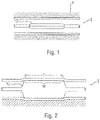
- angioplasty balloons are expanded from a deflated, folded state to an expanded state within a vessel to treat a target area, such as a portion of the circumferential inner wall I of a blood vessel V, as shown in Figures 1 and 2 .
- the inflation is traditionally completed using an X-ray contrast agent to provide better visibility under X-ray or other form of radiography during the interventional procedure, as illustrated in Figures 3 and 3a .
- a 70/30 percent mixture of contrast agent and saline is used to inflate the balloon during an angioplasty procedure.
- a desirable goal is to reduce inflation and deflation times required for balloons without sacrificing the profile of the balloons, especially for large volume balloons (which can require up to two minutes of inflation/deflation times with the contrast agent).
- the use of contrast agent prolongs the inflation/deflation times and also poses the risk of iodine exposure to patients sensitive to iodine.
- a non-radiopaque substance could be used in lieu of the contrast agent, such as for example saline or carbon dioxide, but such substances are invisible during X-ray imaging, and thus do not enhance visibility.
- the physician performing the angioplasty procedure should be able to locate the position of the uninflated balloon with accuracy, so that the balloon will be properly positioned once inflated. This is conventionally accomplished by attaching marker bands on the catheter shaft in the region corresponding to the balloon working surface.
- This "working surface” is the surface along the portion of the balloon that is used to achieve the desired treatment effect, such as contacting the calcified plaque (which surface in the case of a balloon having conical or tapering sections at the proximal and distal ends is typically co-extensive with a generally cylindrical barrel section).
- misalignment amount X between each interior marker band M carried by shaft S and working surface W of balloon 12, which also typically includes a radiopaque tip P at the distal end.
- the resulting misalignment may prevent the clinician from accurately identifying the location of the working surface of the balloon during an interventional procedure, This may lead to a geographic misplacement, or "miss," of the intended contact between the target area T and the working surface W of the balloon 12 (see Figure 2 ). It is especially desirable to avoid such an outcome when the balloon is designed to deliver a payload (such as a drug, stent, or both) or a working element to a specified location within the vasculature, since a miss may prolong the procedure (such as, for example, by requiring redeployment of the balloon 12 or the use of another balloon catheter in the case of a drug coated balloon).
- a payload such as a drug, stent, or both
- the balloon may also be subject to a phenomenon known as "pancaking," In this condition, the balloon 12 folds down upon itself to a flattened state, as shown in Figure 5 . This situation may cause the balloon to be viewed through fluoroscopy as perhaps still being in the inflated condition, since the full width of the balloon may still be perceived. This can give the clinician the false perception that the balloon remains inflated, when in fact it is not.
- the need is identified for a balloon for which the working surface may be identified during an interventional procedure with enhanced precision.
- WO 2010/027998 Al discloses a radiopaque balloon with a composite wall having a radiopaque adhesive affixing inner and outer layers of the balloon.
- the present invention is directed to the medical balloon of claim 1 and the method of claim 6.
- the dependent claims refer to preferred embodiments.
- the radiopaque material comprises a lattice
- the method includes associating the lattice with the parison or the medical balloon.
- the method may comprise inserting the lattice into the parison or balloon using the mandrel. This may be done after the mandrel is compressed.
- the invention of claim 1 pertains to a medical balloon or a parison for forming a medical balloon and a mandrel including a lattice comprising a radiopaque material and configured for insertion into and expanding within the medical balloon or the parison.
- the lattice may include a longitudinal dimension corresponding to a working surface of the balloon.
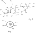
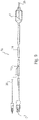
- a catheter 10 having a distal portion 11 with a balloon 12 mounted on a catheter tube 14.
- the balloon 12 has an intermediate section 16, or "barrel,” and end sections 18, 20.
- the end sections 18, 20 reduce in diameter to join the intermediate section 16 to the catheter tube 14 (and thus sections 18, 20 are generally termed cones or cone sections).
- the balloon 12 is sealed at balloon ends (proximal end 15a and distal end 15b) on the cone sections 18, 20 to allow the inflation of the balloon 12 via one or more inflation lumens 17 extending within catheter tube 14 and communicating with the interior of the balloon 12.
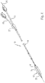
- the catheter tube 14 also includes an elongated, tubular shaft 24 forming a guidewire lumen 23 that directs the guidewire 26 through the catheter 10, and along the distal end of which the balloon 12 may be located.
- this guidewire 26 may extend through the proximal end of the catheter 10 and a first port 25 of a connector 27 into the lumen 23 to achieve an "over the wire” (OTW) arrangement, but could also be provided in a "rapid exchange"' (RX) configuration, in which the guidewire 26 exits a lateral opening 14a closer to the distal end (see Figure 9 ) or else is fed through the tip at a passage distally of the balloon 12 ("short" RX; not shown).
- a second port 29 may also be associated with catheter 10, such as by way of connector 27, for introducing a fluid (e.g., saline, a contrast agent, or both) into the interior compartment, of the balloon 12 via the inflation lumen 17,
- Balloon 12 may include a single or multi-layered balloon wall 28 forming the interior for receiving the inflation fluid.
- the balloon 12 may be a non-compliant balloon having a balloon wall 28 that maintains its size and shape in one or more directions when the balloon is inflated. Examples of non-compliant balloons may be found in U.S. Pat. No. 6,746,425 and Publication Nos.
- the balloon 12 in such case also has a pre-determined surface area that remains constant during and after inflation, also has a pre-determined length and pre-determined diameter that each, or together, remain constant during and after inflation.
- the balloon 12 could be semi-compliant or compliant instead, depending on the particular use.
- the balloon 12 may have a modified portion having a radiopaque quality.
- this radiopaque quality is provided in a manner that allows for a clinician to differentiate, with relative ease and high precision, one portion of the balloon 12 from another (such as, but not limited to, the barrel section 16 including the working surface W from the cone sections 18, 20). This helps the clinician ensure the accurate positioning of the balloon 12 and, in particular, a portion of or the entire working surface W, at a specified treatment location, which may be especially desirable in the delivery of drugs via the balloon working surface W, as outlined in more detail in the following description.
- the radiopaque quality is achieved by providing one or more at least partially radiopaque markings 30.
- the marking or markings 30 may be provided along the balloon 12 to create a defined portion as the working surface W, as contrasted with the full length L of the balloon.
- a marking 30 extend along the balloon 12 in a longitudinal direction along the barrel section 16 and over the entire circumference of the working surface W.
- the marking 30 may extend over only a portion of the working surface W, or may extend over only a different part of the balloon 12 (such as the cone sections 18, 20), as outlined further in the following description.
- This marking 30 may be provided during a process used to form the balloon 12 having the desired shape created by a multi-layered wall 28.
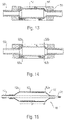
- a first tube 50 comprising a thin layer of material (such as a polymer), may be inserted within a second tube 52, to form a parison 54, as shown in Figures 11 (perspective view) and 11a (cross-section).
- the second tube 52 may also comprise a compatible polymeric material, but could also be formed of a different material (such as metal, including possibly a film).
- the second tube 52 includes the one or more radiopaque markings 30, which may correspond in length to the barrel section 16 of the finished balloon, as shown in Figure 11 (but the second tube could extend the entire length of the balloon 12, as discussed below and illustrated by .inner tube 62 in Figure 18 ).
- the first, inner tube 50 may then be expanded to form a multi-layered balloon 12 ( Figure 12 ), with the second, outer tube 52 thus forming a radiopaque outer sleeve, as shown in the cross-sectional view of Figure 12a .
- this processing may be achieved using a blow mold 54 having separable portions forming a mold cavity 56 corresponding in shape to the desired shape of the balloon.
- the outer tube 52 may be pre-positioned in the mold cavity 56, including possibly within a correspondingly shaped recess formed along one or more of the interior surfaces of the mold 55.
- the inner tube 50 may then be expanded using heat and pressure to form the balloon 12 with the desired shape, and having the outer tube 52 intimately bonded to it.
- Figure 14 shows that, instead of a single tube 52, two spaced rubes, such as radiopaque collars 52a, 52b, may be provided on the inner tube 50 in order to provide spaced markings 30 on the finished balloon 12 (see Figure 19 ).
- these collars 52a, 52b may be pre-positioned in the mold cavity 56 so as to receive the inner tube 50 when inserted.
- the collars 52, 52b may be comprised of a thin flexible, material (e.g., a polymer, such as nylon) compatible with the material (e.g., a polymer, such as nylon) of the adjacent layer formed by tube 50, but could also be made of different materials, such as one or more metal foils.
- the collars 52a, 52b are intimately bonded to form a balloon 12 with spaced, radial markers, which as the result of the positioning at pre-determined locations in the mold cavity 56 may align precisely with the edges of the working surface W.
- the markings 30 may be provided on the tube 52 (or tubes 52a, 52b) in various ways.
- the markings 30 may be provided by applying a radiopaque material to the tube 52 at the desired location in any shape, pattern or form (including possibly alphanumeric characters to provide information that can be perceived under fluoroscopy, such as a length, diameter, logo, trademark, rated burst pressure, or balloon type). This may be done by inking, spraying, printing, or painting the radiopaque material in fluid form on the surface of the tube 52 (possibly with the application of a mask or the like, in which case the techniques of dipping or rolling in the radiopaque material to form the desired coating could be used).
- the marking 30 may be embedded in the tube 52, including for example by providing it as part of a film or a felt, or in a bonding agent or adhesive used to bond multiple layers together to form the tube 52 (see, e.g., U.S. Patent Application Publication No. 2011/0160661 ).
- the marking 30 may be provided during the process of fabricating the tube 52, such as for example during a co-extrusion process. Examples of such techniques are described in international application PCT/US 13/29974 .
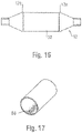
- the mold cavity may be adapted to form the balloon 12 with the desired shape and appearance, and could also be adapted to form shoulders 12a on the balloon 12 once blown. These shoulders 12a may help to retain the outer tube 52 providing the modified portion of the balloon 12 against movement in the longitudinal direction, and thus help to ensure that it remains positioned at the desired location (again, in one embodiment, aligned with the full extent of the working surface W). Additionally or alternatively, as shown in Figure 17 , the inner surface of the outer tube 52 may be adapted for fractionally engaging the outer surface of the tube 50, such as by providing a roughened or textured surface 58.
- an adhesive may be used to improve the bond between the tubes 50, 52.
- This adhesive may be provided on either tube prior to blow molding.
- the adhesive may also optionally be provided with a radiopacifier in order to enhance the radiopaque quality of the balloon 12 (see, e.g., U.S. Patent Application Publication No. 2011/0160661 ).
- a parison 60 may include an inner layer comprising a radiopaque film 62, and an outer layer 64 comprising a traditional film that is not made radiopaque by an additive.
- the blow molding process expands the parison 60 to thus form a balloon 12 having a radiopaque quality corresponding to the length of the inner layer including radiopacifier, which may be the full length L of the balloon 12.
- a balloon may be formed by stretching a polymer tube of constant wall thickness to a desired or preferred shape wherein the barrel portion is larger in diameter than other portions intended to be the cones or shoulders of the formed balloon.
- Such a process may be achieved by placing a balloon parison in to a mold and altering the physical surroundings, such as increasing temperature and/or applying pressure, such as through increased fluid (gas or liquid) pressure, to allow the parison to take the shape of the surrounding mold.
- Balloons 12 that incorporate coatings comprising drugs to be applied to the vasculature may also benefit from the above-referenced embodiments.
- a balloon 12 including a defined working surface W such as by providing radiopaque markings 30 at the transitions between the barrel section 16 and cone sections 18, 20, may include a portion coated with such a drug D, such as one designed for achieving a desired therapeutic effect when applied to the interior of the vessel.
- the radiopaque marking 30 may also correspond to the location of the drug D on the balloon 12, such as along the entire working surface W or only a portion of it.
- the drag D may be applied to the inflated balloon as part of the manufacturing process, and prior to folding for insertion in the vasculature. The clinician may thus with the benefit of a fluoroscope determine the precise positioning of the working surface W prior to inflating the balloon 12 in the vasculature to deliver the drug D to the desired location and provide the desired treatment regimen.
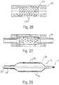
- the markings 30 may also be provided as one or more longitudinal strips 66 that do not extend along the entire circumference of the balloon 12, as shown in Figures 20 and 21 . This may be achieved by providing one or both of the layers 62, 64, or the tube 52, with radiopaque material corresponding to the strips 66, such as by a co-extrusion process. Additional details are provided in PCT/US13/29959 , PCT/US13/29967 , PCT/EP13/54748 , and PCT/US13/29977 . The presence of plural spaced markings 30 in this manner may also help to distinguish between the inflated condition (in which the markings are spaced), and the properly deflated condition, as the markings would be closer to each other when the balloon is folded.
- the blow molding operation may be arranged to create a balloon 12 with a different type of modified layer.
- an insert 52 may be provided with a functional modification, such as an outer surface that is textured or etched, and associated with an inner tube 50.
- the insert 52 could be made partially or fully radiopaque if desired (see, e.g., Figure 10 ), but such is considered optional.
- a multi-layered insert 52 may be provided with an outer radiopaque layer 51a and an inner support layer 51b that is not enhanced with a radiopacifier and exposed by the openings 53 formed by etchings in the outer layer (see Figure 22a ). This may create a particular pattern under fluoroscopy, which may allow for the detection of the locations on the balloon 12 where a drug is present (either on the etched portions or the unetched portions, as desired, which again may correspond to the working surface W).
- a balloon 12 may be formed having an etched or textured outer surface layer 28a of the balloon wall 28.
- This layer 28a may extend along the entire working surface W, as shown in Figure 23 , or any portion of it.
- the material forming the insert 52 should have a sufficiently high melt flow index such that the features are not caused to disappear as the result of the heat and pressure created during the blow molding process.
- the insert 52 may be provided as a reticulated or fenestrated body, such as a mesh, screen or lattice having a plurality of crossing members 57 forming openings 53.
- the body 52 may be tubular in form, as shown, and could comprise more than one piece or part (similar to collars 52a, 52b).
- the material forming the insert 52 should have a sufficiently high melt flow index such that the features are not caused to disappear as the result of the heat and pressure created during the blow molding process.
- the insert 52 bonds to an inner tube 50 and forms an outer layer of the finished balloon 12.
- the openings 53 expose the balloon wall 28, which may be adapted to form the modified layer (such as by being radiopaque).
- the body 52 may extend along the entire working surface W, and may optionally be fully or partially radiopaque. Alternatively, the body 52 may be provided with a coating, such as in the form of a drug or an agent providing enhanced lubricity.
- the mold 55 may be modified to provide a surface treatment on the finished balloon 12.
- the inner surfaces of the mold cavity 56 may be provided with a textured pattern 56a, such as by etching, engraving, or the like, so as to form inwardly directed projections. This includes along the portions corresponding to the working surface W of the balloon 12 (e.g., the barrel section).
- a parison 54 which may be a single layer of material
- the surface of the resulting balloon 12 is provided with a corresponding pattern in the form of an impression of the pattern in the mold 55.
- the projections forming the pattern 56a in the mold form depressions in the outer surface of the balloon wall 28.
- An option in this example is to deposit a material within the mold cavity 56 to partially or completely fill any spaces or gaps formed in the pattern 56a, such as for example a radiopacifier 59.
- a material within the mold cavity 56 such as for example a radiopacifier 59.
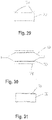
- the balloon 12 resulting from blow molding using a mold 55 with this type of pattern 56a with a filler would thus have a surface layer modified to including the selected filler material (which in the case of a radiopacifier 59 would make the surface partially radiopaque, as shown by the darkened portions of the balloon wall 28 in Figure 28 ).
- the depositing of the material within the mold 55 may be done by injection through an internal passageway opening within the cavity 56, either before or during the molding process, including possibly by spraying the filler material within the mold cavity 56 (such as when the mating portions forming the mold 55 are separated to expose the surface pattern 56a).
- the balloon catheter 10 may be formed by forming a balloon parison with discrete radiopaque segments introduced by coextrusion.
- the coextrusion may involve the use of a rotating die (see, e.g. U.S. Patent Application Publication No. 2003/0100869 ) to form discrete sections within the tube of one or more materials, such as a radiopaque material.
- the parison may then he blow molded to form the balloon, with the radiopaque material then embedded in the walls thereof (such as between, the ends of the working surface, along the entire working surface, along one or both of the end sections or cones (see, e.g.. Figures 19-21 ), and in all cases either partly or fully providing coverage of the respective surfaces).
- the markings 30 may further be introduced into the balloon 12 through application of a radiopaque felt.
- a radiopaque felt 72 may also be applied to the exterior of a formed balloon 12, optionally followed by a secondary process, such as lamination (note film 74), to thereby secure the felt in position.
- the radiopaque felt 72 may be applied over an extruded tube 76, followed by a secondary extrusion step, e.g. wire coating, to secure the felt.
- the dual-layer tubing may then be formed into a balloon 12 by steps such as blow-molding or other similar processes known in the art
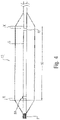
- radiopaque material may also be applied to an inner lumen of a balloon parison 80 or fully-formed balloon 12 through the use of an expanding mandrel 82.
- the mandrel 82 may comprise a rigid portion 82a with a distally fixed expandable portion 82b that can have both a retracted configuration, and an expanded configuration.
- the distal section may be sized to efface the inner lumen of the balloon parison 80 when in the expanded configuration, yet still able to pass through both proximal and distal ends thereof in the retracted configuration.
- the distal end of the mandrel 82 should be constructed of a material that can withstand gas and/or liquid pressure, such as a compliant balloon.
- the mandrel 82 may also be comprised of opposed and/or interwoven struts arranged in a manner such that expansion may be achieved during contraction (e.g. a helically wound braid, such as a biaxial braid, wherein reduced angle between the warp and weft at crossing points in turn reduces radial distance between opposing sides) or as opposing struts connected in the middle and at each end are affected by a pivoting joint (e.g. a pantographic mechanism).
- a helically wound braid such as a biaxial braid, wherein reduced angle between the warp and weft at crossing points in turn reduces radial distance between opposing sides
- a pivoting joint e.g. a pantographic mechanism
- the radiopaque material or a portion thereof may also be introduced to the balloon parison prior to molding.
- a radiopaque material such as a film or a felt, that comprises a radiopaque material (e.g. tungsten, barium, tantalum, gold, platinum) with the addition of polymers to provide a structural matrix, as well as optionally stabilizers and/or plasticizers, can be applied to the parison prior to molding. Rolling or folding the radiopaque material allows the material to efface an inner lumen of the parison as it expands following insertion and up to or during a molding step.
- a radiopaque material such as a film or a felt, that comprises a radiopaque material (e.g. tungsten, barium, tantalum, gold, platinum) with the addition of polymers to provide a structural matrix, as well as optionally stabilizers and/or plasticizers, can be applied to the parison prior to molding. Rolling or folding the radiopaque material allows
- an adhesive applied to the exterior of the radiopaque material prior to insertion into the parison may further enhance in adhering the material to the balloon catheter lumen.
- expansion of the distal tip of the mandrel discussed herein will further secure the radiopaque material.
- the markings 30 may also be introduced to the balloon 12 as a solution.
- a solution comprising radiopaque material 86 in suspension optionally aided by stabilizers, may be applied to the outer lumen of the expandable mandrel 82.
- the distal portion of the expandable mandrel can then be inserted into a balloon parison (e.g., the example provided in Figure 32 ) with the mandrel in a retracted configuration (e.g., deflated, in the case of a balloon).
- the mandrel 82 can then move to the expanded configuration to efface the parison lumen and similarly deposit the solution on the lumen surface, and the parison then used to form the balloon 12.
- a radiopaque solution may be applied by the expandable mandrel after the balloon is fully formed.
- the markings 30 may also comprise radiopaque fibers.
- Fibers comprised of a radiopaque material, such as tungsten, tantalum, platinum or similar can be achieved through a polymer matrix and optionally formed through an extrusion process. Fibers can then be introduced to the balloon through the use of the expandable mandrel 80 as discussed herein.
- the mandrel 82 can be sized in such a manner that it can be inserted in through the proximal and distal ends of the balloon parison 80 in the retracted configuration and so that it can fully efface the inner lumen of the parison in the expanded configuration.
- fibers 88 can be arranged in a radial configuration around the mandrel 82 prior to insertion into the parison 80. Following expansion of the mandrel 82, the fibers may be deposited on the inner lumen of the parison 80, after which the mandrel can be reduced to the retracted configuration and withdrawn. Fibers may be adhered to the inner lumen through the use of an adhesive, and optionally later cured during a secondary process, such as exposure to UV light, heat, or flash-off solvents.
- the marking 30 is introduced to the balloon 12 as a lattice or matrix 90 of radiopaque material, as shown in Figure 35 .
- Flexible polymers embedded with radiopaque material may be formed by extrusion, optionally followed by cutting to form the lattice and thus reduce the surface area for increased flexibility.
- the outer diameter of the lattice or matrix 90 may be sized to efface the inner lumen of a balloon parison 80 and the length of the lattice selected to correspond to the balloon barrel portion or to the cone/shoulder portions.
- the lattice may be compressed to a smaller diameter to allow for insertion in the parison 80 through the open ends corresponding to the proximal or distal cone regions.
- An adhesive may further be introduced to assist in anchoring to the inner lumen.
- the marking 30 may also be applied to the balloon 12 as a powder.
- Adhesion of a radiopaque powder may be achieved through selective application of an adhesive to the inner lumen of a parison for forming the balloon.
- An insert such as a hypo-tube
- An applicator e.g., a swab or sponge at the distal end, which may be expandable
- the swab or sponge may then selectively be used to efface the cone portion of the balloon, followed by administration of an adhesive through the insert.
- adhesive is selectively applied to the inner lumen by the sponge.
- the balloon may then be optionally moved or rotated to enhance even distribution.
- the insert hyper-tube
- the insert may then be retracted and repeated through the opposing end of the balloon as needed.
- radiopaque material which may be in the form of a powder
- Powder not adhered to the lumen may then be removed prior to introduction of the catheter shaft.
- a powder may be combined with the adhesive and then applied to the inner lumen through techniques such as brush coating, spray coating or flush and fill.
- Radiopaque (RO) powder was weighed in a 20 ml glass vial which then UV light curing adhesive, 208-CTH-F Dymax (Torrington, CT) was also added. The percentages of the components were totaled to one hundred percent (100%).
- the RO coating mixture was thoroughly mixed and transferred to a 3cc polypropylene syringe which was then placed onto a syringe pump for coating. Attached a nozzle (i.e. EFD needle tip) to the 3cc syringe and the nozzle was inserted into the lumen diameter of the balloon neck for luminal coating, only the shoulders of the balloon were coated. The infusing rate was set at 0.5 ml/minute.
- radiopaque materials include, but are not limited to, finely divided tungsten, tantalum, bismuth, bismuth trioxide, bismuth oxychloride, bismuth subcarbonate, other bismuth compounds, barium sulfate, tin, silver, silver compounds, rare earth oxides, and many other substances commonly used for X-ray absorption.
- the polymer used for making a film, possible with a radiopaque material may be any polymeric material which can be loaded with radiopacifier and formed into a sufficiently thin film. Examples of polymers include thermoplastic and thermoset polymers.
- thermoplastic polymers include, but are not limited to, polyurethanes, polyamides (nylon 11, nylon 12), polyetherpolyamide copolymers such as PEBAX, polyethylene terephthalate or other polyesters, polyvinyl acetate, polyvinyl chloride, and many other thermoplastic materials useful for making films.
- thermoset polymers include, but are not limited to, crosslinked polyurethanes, polyureas, epoxies, acrylics, silicones, and many other thermoset materials that can be formed into thin structures, including films. Any adjacent structures to be bonded, such as tubes 50, 52 or layers 62, 64, may be formed of compatible materials, which may avoid additional processing or the inclusion of a compatibilizer, tie layer or the like.
Landscapes
- Engineering & Computer Science (AREA)
- Health & Medical Sciences (AREA)
- Mechanical Engineering (AREA)
- Life Sciences & Earth Sciences (AREA)
- Heart & Thoracic Surgery (AREA)
- Manufacturing & Machinery (AREA)
- Pulmonology (AREA)
- Biophysics (AREA)
- Child & Adolescent Psychology (AREA)
- Anesthesiology (AREA)
- Biomedical Technology (AREA)
- Hematology (AREA)
- Animal Behavior & Ethology (AREA)
- General Health & Medical Sciences (AREA)
- Public Health (AREA)
- Veterinary Medicine (AREA)
- Media Introduction/Drainage Providing Device (AREA)
- Blow-Moulding Or Thermoforming Of Plastics Or The Like (AREA)
- Prostheses (AREA)
Description
- This application claims the benefit of
U.S. Provisional Patent Application Ser. No. 61/870,913 - This disclosure relates generally to balloons for performing medical procedures, such as angioplasty and, more particularly, to a balloon that is at least partially radiopaque and related methods for forming such a balloon.
- Balloons are routinely used to resolve or address flow restrictions or perhaps even complete blockages in tubular areas of the body, such as arteries or veins. In many clinical situations, the restrictions are caused by hard solids, such as calcified plaque, and require the use of high pressures to compact such blockages. Commercially available balloons employ complex technology to achieve high pressure requirements without sacrificing the profile of the balloon. Besides high pressure requirements, the balloons should also be resistant to puncture, easy to track and push, and present a low profile, especially when used for angioplasty.
- In clinical practice, angioplasty balloons are expanded from a deflated, folded state to an expanded state within a vessel to treat a target area, such as a portion of the circumferential inner wall I of a blood vessel V, as shown in
Figures 1 and 2 . The inflation is traditionally completed using an X-ray contrast agent to provide better visibility under X-ray or other form of radiography during the interventional procedure, as illustrated inFigures 3 and 3a . Typically, a 70/30 percent mixture of contrast agent and saline is used to inflate the balloon during an angioplasty procedure. - In general, a desirable goal is to reduce inflation and deflation times required for balloons without sacrificing the profile of the balloons, especially for large volume balloons (which can require up to two minutes of inflation/deflation times with the contrast agent). Because of its relatively high viscosity, it would also be desirable to eliminate, or at least reduce the amount of, the contrast agent used in inflation/deflation of the balloons. The use of contrast agent prolongs the inflation/deflation times and also poses the risk of iodine exposure to patients sensitive to iodine. In this regard, a non-radiopaque substance could be used in lieu of the contrast agent, such as for example saline or carbon dioxide, but such substances are invisible during X-ray imaging, and thus do not enhance visibility.
- Furthermore, the physician performing the angioplasty procedure should be able to locate the position of the uninflated balloon with accuracy, so that the balloon will be properly positioned once inflated. This is conventionally accomplished by attaching marker bands on the catheter shaft in the region corresponding to the balloon working surface. This "working surface" is the surface along the portion of the balloon that is used to achieve the desired treatment effect, such as contacting the calcified plaque (which surface in the case of a balloon having conical or tapering sections at the proximal and distal ends is typically co-extensive with a generally cylindrical barrel section).
- Misalignment of the marker bands during placement along the shaft sometimes results in their failure to correspond precisely to the extent of the working surface, as is shown in
Figure 4 (note misalignment amount X between each interior marker band M carried by shaft S and working surface W ofballoon 12, which also typically includes a radiopaque tip P at the distal end). Even upon exercising great care to position the markers properly on the underlying shaft in alignment with anticipated boundaries of the working surface when the balloon is inflated, there remains a tendency for mismatch due to several possible factors. One such factor may be the tolerance stackups arising as a consequence of the affixation of the balloon to the distal end of the catheter shaft. The balloon also has a tendency to grow in the longitudinal direction when inflated, especially with large and particularly long balloons. Another factor is the tendency of the portion of the catheter shaft within the balloon to bend or flex during inflation. This may lead to misalignment between radiopaque markers fixed to the shaft and the working surface. - Whatever the cause, the resulting misalignment may prevent the clinician from accurately identifying the location of the working surface of the balloon during an interventional procedure, This may lead to a geographic misplacement, or "miss," of the intended contact between the target area T and the working surface W of the balloon 12 (see
Figure 2 ). It is especially desirable to avoid such an outcome when the balloon is designed to deliver a payload (such as a drug, stent, or both) or a working element to a specified location within the vasculature, since a miss may prolong the procedure (such as, for example, by requiring redeployment of theballoon 12 or the use of another balloon catheter in the case of a drug coated balloon). - Upon deflation, the balloon may also be subject to a phenomenon known as "pancaking," In this condition, the
balloon 12 folds down upon itself to a flattened state, as shown inFigure 5 . This situation may cause the balloon to be viewed through fluoroscopy as perhaps still being in the inflated condition, since the full width of the balloon may still be perceived. This can give the clinician the false perception that the balloon remains inflated, when in fact it is not. - Accordingly, the need is identified for a balloon for which the working surface may be identified during an interventional procedure with enhanced precision.
-
WO 2010/027998 Al discloses a radiopaque balloon with a composite wall having a radiopaque adhesive affixing inner and outer layers of the balloon. - The present invention is directed to the medical balloon of claim 1 and the method of claim 6. The dependent claims refer to preferred embodiments.
- The radiopaque material comprises a lattice, and the method includes associating the lattice with the parison or the medical balloon. The method may comprise inserting the lattice into the parison or balloon using the mandrel. This may be done after the mandrel is compressed.
- The invention of claim 1 pertains to a medical balloon or a parison for forming a medical balloon and a mandrel including a lattice comprising a radiopaque material and configured for insertion into and expanding within the medical balloon or the parison. The lattice may include a longitudinal dimension corresponding to a working surface of the balloon.
-
-
Figures 1 - 9 are illustrative of the background of the invention; -
Figure 10 illustrates a first example not having all features of claim 1; -
Figures 11 - 11a and 12 - 12a show a manufacturing technique for forming theFigure 10 example; -
Figures 13 and 14 further shown manufacturing techniques; -
Figure 15 illustrates a further example not having all features of claim 1; -
Figures 16 and 17 illustrate another example not having all features of claim 1; -
Figures 18-21 show still further examples not having all features of claim 1; -
Figures 22 and 22a are cross-sectional side and end views of another example not having all features of claim 1; -
Figure 23 is a side view of a balloon catheter formed according to one aspect of an example not having all features of claim 1; -
Figures 24 and 25 show a further example not having all features of claim 1; and -
Figures 26-31 ,33 and34 show still further examples not having all features of claim 1; -
Figures 32 and 35 show embodiments of the invention. - Provided is a catheter 10 having a
distal portion 11 with aballoon 12 mounted on acatheter tube 14. Referring toFigures 6, 7 , and8 , theballoon 12 has anintermediate section 16, or "barrel," andend sections end sections intermediate section 16 to the catheter tube 14 (and thussections balloon 12 is sealed at balloon ends (proximal end 15a and distal end 15b) on thecone sections balloon 12 via one ormore inflation lumens 17 extending withincatheter tube 14 and communicating with the interior of theballoon 12. - The
catheter tube 14 also includes an elongated,tubular shaft 24 forming aguidewire lumen 23 that directs theguidewire 26 through the catheter 10, and along the distal end of which theballoon 12 may be located. As illustrated inFigure 8 , thisguidewire 26 may extend through the proximal end of the catheter 10 and afirst port 25 of aconnector 27 into thelumen 23 to achieve an "over the wire" (OTW) arrangement, but could also be provided in a "rapid exchange"' (RX) configuration, in which theguidewire 26 exits a lateral opening 14a closer to the distal end (seeFigure 9 ) or else is fed through the tip at a passage distally of the balloon 12 ("short" RX; not shown). Asecond port 29 may also be associated with catheter 10, such as by way ofconnector 27, for introducing a fluid (e.g., saline, a contrast agent, or both) into the interior compartment, of theballoon 12 via theinflation lumen 17, -
Balloon 12 may include a single ormulti-layered balloon wall 28 forming the interior for receiving the inflation fluid. Theballoon 12 may be a non-compliant balloon having aballoon wall 28 that maintains its size and shape in one or more directions when the balloon is inflated. Examples of non-compliant balloons may be found inU.S. Pat. No. 6,746,425 and Publication Nos. -
- The
balloon 12 in such case also has a pre-determined surface area that remains constant during and after inflation, also has a pre-determined length and pre-determined diameter that each, or together, remain constant during and after inflation. However, theballoon 12 could be semi-compliant or compliant instead, depending on the particular use. - In order to provide for enhanced locatability during an mterventional procedure, the
balloon 12 may have a modified portion having a radiopaque quality. In one embodiment, this radiopaque quality is provided in a manner that allows for a clinician to differentiate, with relative ease and high precision, one portion of theballoon 12 from another (such as, but not limited to, thebarrel section 16 including the working surface W from thecone sections 18, 20). This helps the clinician ensure the accurate positioning of theballoon 12 and, in particular, a portion of or the entire working surface W, at a specified treatment location, which may be especially desirable in the delivery of drugs via the balloon working surface W, as outlined in more detail in the following description. - With initial reference to
Figure 10 , the radiopaque quality is achieved by providing one or more at least partiallyradiopaque markings 30. The marking ormarkings 30 may be provided along theballoon 12 to create a defined portion as the working surface W, as contrasted with the full length L of the balloon. For example, a marking 30 extend along theballoon 12 in a longitudinal direction along thebarrel section 16 and over the entire circumference of the working surface W. Alternatively, the marking 30 may extend over only a portion of the working surface W, or may extend over only a different part of the balloon 12 (such as thecone sections 18, 20), as outlined further in the following description. - This marking 30 may be provided during a process used to form the
balloon 12 having the desired shape created by amulti-layered wall 28. In particular, afirst tube 50 comprising a thin layer of material (such as a polymer), may be inserted within asecond tube 52, to form aparison 54, as shown inFigures 11 (perspective view) and 11a (cross-section). Thesecond tube 52 may also comprise a compatible polymeric material, but could also be formed of a different material (such as metal, including possibly a film). Thesecond tube 52 includes the one or moreradiopaque markings 30, which may correspond in length to thebarrel section 16 of the finished balloon, as shown inFigure 11 (but the second tube could extend the entire length of theballoon 12, as discussed below and illustrated by .inner tube 62 inFigure 18 ). The first,inner tube 50 may then be expanded to form a multi-layered balloon 12 (Figure 12 ), with the second,outer tube 52 thus forming a radiopaque outer sleeve, as shown in the cross-sectional view ofFigure 12a . - Turning to
Figure 13 , it can be understood that this processing may be achieved using ablow mold 54 having separable portions forming amold cavity 56 corresponding in shape to the desired shape of the balloon. Theouter tube 52 may be pre-positioned in themold cavity 56, including possibly within a correspondingly shaped recess formed along one or more of the interior surfaces of themold 55. Theinner tube 50 may then be expanded using heat and pressure to form theballoon 12 with the desired shape, and having theouter tube 52 intimately bonded to it. -
Figure 14 shows that, instead of asingle tube 52, two spaced rubes, such asradiopaque collars inner tube 50 in order to provide spacedmarkings 30 on the finished balloon 12 (seeFigure 19 ). Liketube 52, thesecollars mold cavity 56 so as to receive theinner tube 50 when inserted. As noted above fortube 52, thecollars tube 50, but could also be made of different materials, such as one or more metal foils. Upon expanding theinner tube 50, thecollars balloon 12 with spaced, radial markers, which as the result of the positioning at pre-determined locations in themold cavity 56 may align precisely with the edges of the working surface W. - The
markings 30 may be provided on the tube 52 (ortubes markings 30 may be provided by applying a radiopaque material to thetube 52 at the desired location in any shape, pattern or form (including possibly alphanumeric characters to provide information that can be perceived under fluoroscopy, such as a length, diameter, logo, trademark, rated burst pressure, or balloon type). This may be done by inking, spraying, printing, or painting the radiopaque material in fluid form on the surface of the tube 52 (possibly with the application of a mask or the like, in which case the techniques of dipping or rolling in the radiopaque material to form the desired coating could be used). Alternatively, the marking 30 may be embedded in thetube 52, including for example by providing it as part of a film or a felt, or in a bonding agent or adhesive used to bond multiple layers together to form the tube 52 (see, e.g.,U.S. Patent Application Publication No. 2011/0160661 ). - The marking 30 may be provided during the process of fabricating the
tube 52, such as for example during a co-extrusion process. Examples of such techniques are described in international applicationPCT/US 13/29974 . - As perhaps best understood with reference to
Figures 15 and16 , the mold cavity may be adapted to form theballoon 12 with the desired shape and appearance, and could also be adapted to formshoulders 12a on theballoon 12 once blown. Theseshoulders 12a may help to retain theouter tube 52 providing the modified portion of theballoon 12 against movement in the longitudinal direction, and thus help to ensure that it remains positioned at the desired location (again, in one embodiment, aligned with the full extent of the working surface W). Additionally or alternatively, as shown inFigure 17 , the inner surface of theouter tube 52 may be adapted for fractionally engaging the outer surface of thetube 50, such as by providing a roughened or textured surface 58. - Additionally or alternatively, an adhesive may be used to improve the bond between the
tubes U.S. Patent Application Publication No. 2011/0160661 ). - Another example involves forming the
balloon 12 with a modified portion by blow molding a multi-layered parison, wherein at least one of the layers of the parison comprises a radiopaque material. Thus, for example, aparison 60 may include an inner layer comprising aradiopaque film 62, and anouter layer 64 comprising a traditional film that is not made radiopaque by an additive. The blow molding process expands theparison 60 to thus form aballoon 12 having a radiopaque quality corresponding to the length of the inner layer including radiopacifier, which may be the full length L of theballoon 12. - A balloon may be formed by stretching a polymer tube of constant wall thickness to a desired or preferred shape wherein the barrel portion is larger in diameter than other portions intended to be the cones or shoulders of the formed balloon. Such a process may be achieved by placing a balloon parison in to a mold and altering the physical surroundings, such as increasing temperature and/or applying pressure, such as through increased fluid (gas or liquid) pressure, to allow the parison to take the shape of the surrounding mold.
-
Balloons 12 that incorporate coatings comprising drugs to be applied to the vasculature may also benefit from the above-referenced embodiments. For example, as shown inFigure 19 , aballoon 12 including a defined working surface W, such as by providingradiopaque markings 30 at the transitions between thebarrel section 16 andcone sections radiopaque marking 30 may also correspond to the location of the drug D on theballoon 12, such as along the entire working surface W or only a portion of it. The drag D may be applied to the inflated balloon as part of the manufacturing process, and prior to folding for insertion in the vasculature. The clinician may thus with the benefit of a fluoroscope determine the precise positioning of the working surface W prior to inflating theballoon 12 in the vasculature to deliver the drug D to the desired location and provide the desired treatment regimen. - The
markings 30 may also be provided as one or morelongitudinal strips 66 that do not extend along the entire circumference of theballoon 12, as shown inFigures 20 and 21 . This may be achieved by providing one or both of thelayers tube 52, with radiopaque material corresponding to thestrips 66, such as by a co-extrusion process. Additional details are provided inPCT/US13/29959 ,PCT/US13/29967 ,PCT/EP13/54748 , andPCT/US13/29977 . The presence of plural spacedmarkings 30 in this manner may also help to distinguish between the inflated condition (in which the markings are spaced), and the properly deflated condition, as the markings would be closer to each other when the balloon is folded. - The blow molding operation may be arranged to create a
balloon 12 with a different type of modified layer. For example, inFigure 22 , aninsert 52 may be provided with a functional modification, such as an outer surface that is textured or etched, and associated with aninner tube 50. Theinsert 52 could be made partially or fully radiopaque if desired (see, e.g.,Figure 10 ), but such is considered optional. In one embodiment, amulti-layered insert 52 may be provided with an outerradiopaque layer 51a and aninner support layer 51b that is not enhanced with a radiopacifier and exposed by theopenings 53 formed by etchings in the outer layer (seeFigure 22a ). This may create a particular pattern under fluoroscopy, which may allow for the detection of the locations on theballoon 12 where a drug is present (either on the etched portions or the unetched portions, as desired, which again may correspond to the working surface W). - In any case, on blow molding the resulting
parison 54 into a corresponding mold 55 (seeFigures 13 and 14 ), aballoon 12 may be formed having an etched or textured outer surface layer 28a of theballoon wall 28. This layer 28a may extend along the entire working surface W, as shown inFigure 23 , or any portion of it. In the case of etching, texturing, or other surface features, the material forming theinsert 52 should have a sufficiently high melt flow index such that the features are not caused to disappear as the result of the heat and pressure created during the blow molding process. - Another example for creating a
balloon 12 with a modified layer is to provide aninsert 52 with one or more openings. For example, as shown inFigure 24 , theinsert 52 may be provided as a reticulated or fenestrated body, such as a mesh, screen or lattice having a plurality of crossingmembers 57 formingopenings 53. Thebody 52 may be tubular in form, as shown, and could comprise more than one piece or part (similar tocollars insert 52 should have a sufficiently high melt flow index such that the features are not caused to disappear as the result of the heat and pressure created during the blow molding process. - When arranged to form a
parsion 54 and blow molded together, theinsert 52 bonds to aninner tube 50 and forms an outer layer of thefinished balloon 12. In the case of aninsert 52 as shown, theopenings 53 expose theballoon wall 28, which may be adapted to form the modified layer (such as by being radiopaque). Thebody 52 may extend along the entire working surface W, and may optionally be fully or partially radiopaque. Alternatively, thebody 52 may be provided with a coating, such as in the form of a drug or an agent providing enhanced lubricity. - It is also possible to modify the
mold 55 to provide a surface treatment on thefinished balloon 12. For example, as shown inFigure 25 , the inner surfaces of themold cavity 56 may be provided with atextured pattern 56a, such as by etching, engraving, or the like, so as to form inwardly directed projections. This includes along the portions corresponding to the working surface W of the balloon 12 (e.g., the barrel section). When a parison 54 (which may be a single layer of material), is then expanded in the mold cavity 56 (Figure 26 ), the surface of the resultingballoon 12 is provided with a corresponding pattern in the form of an impression of the pattern in themold 55. In other words, the projections forming thepattern 56a in the mold form depressions in the outer surface of theballoon wall 28. - An option in this example is to deposit a material within the
mold cavity 56 to partially or completely fill any spaces or gaps formed in thepattern 56a, such as for example a radiopacifier 59. As shown inFigures 27 and 28 , theballoon 12 resulting from blow molding using amold 55 with this type ofpattern 56a with a filler would thus have a surface layer modified to including the selected filler material (which in the case of a radiopacifier 59 would make the surface partially radiopaque, as shown by the darkened portions of theballoon wall 28 inFigure 28 ). The depositing of the material within themold 55 may be done by injection through an internal passageway opening within thecavity 56, either before or during the molding process, including possibly by spraying the filler material within the mold cavity 56 (such as when the mating portions forming themold 55 are separated to expose thesurface pattern 56a). - The balloon catheter 10 may be formed by forming a balloon parison with discrete radiopaque segments introduced by coextrusion. The coextrusion may involve the use of a rotating die (see, e.g.
U.S. Patent Application Publication No. 2003/0100869 ) to form discrete sections within the tube of one or more materials, such as a radiopaque material. The parison may then he blow molded to form the balloon, with the radiopaque material then embedded in the walls thereof (such as between, the ends of the working surface, along the entire working surface, along one or both of the end sections or cones (see, e.g..Figures 19-21 ), and in all cases either partly or fully providing coverage of the respective surfaces). - The
markings 30 may further be introduced into theballoon 12 through application of a radiopaque felt. For example, attachment of aradiopaque felt 72 to a balloon parison 70 (Figure 29 ) may allow for precise identification of each region of the balloon (such as by indicating the portion comprising the working surface relative to other portions). As shown inFigure 30 , theradiopaque felt 72 may also be applied to the exterior of a formedballoon 12, optionally followed by a secondary process, such as lamination (note film 74), to thereby secure the felt in position. Alternatively, as shown inFigure 31 , theradiopaque felt 72 may be applied over an extrudedtube 76, followed by a secondary extrusion step, e.g. wire coating, to secure the felt. In such a ease, the dual-layer tubing may then be formed into aballoon 12 by steps such as blow-molding or other similar processes known in the art - As shown in
Figure 32 , radiopaque material may also be applied to an inner lumen of aballoon parison 80 or fully-formedballoon 12 through the use of an expanding mandrel 82. For example, the mandrel 82 may comprise a rigid portion 82a with a distally fixed expandable portion 82b that can have both a retracted configuration, and an expanded configuration. The distal section may be sized to efface the inner lumen of theballoon parison 80 when in the expanded configuration, yet still able to pass through both proximal and distal ends thereof in the retracted configuration. The distal end of the mandrel 82 should be constructed of a material that can withstand gas and/or liquid pressure, such as a compliant balloon. - The mandrel 82 may also be comprised of opposed and/or interwoven struts arranged in a manner such that expansion may be achieved during contraction (e.g. a helically wound braid, such as a biaxial braid, wherein reduced angle between the warp and weft at crossing points in turn reduces radial distance between opposing sides) or as opposing struts connected in the middle and at each end are affected by a pivoting joint (e.g. a pantographic mechanism).
- The radiopaque material or a portion thereof may also be introduced to the balloon parison prior to molding. For instance, a radiopaque material, such as a film or a felt, that comprises a radiopaque material (e.g. tungsten, barium, tantalum, gold, platinum) with the addition of polymers to provide a structural matrix, as well as optionally stabilizers and/or plasticizers, can be applied to the parison prior to molding. Rolling or folding the radiopaque material allows the material to efface an inner lumen of the parison as it expands following insertion and up to or during a molding step. The addition of an adhesive applied to the exterior of the radiopaque material prior to insertion into the parison may further enhance in adhering the material to the balloon catheter lumen. Those skilled in the art will appreciate that expansion of the distal tip of the mandrel discussed herein will further secure the radiopaque material.
- The
markings 30 may also be introduced to theballoon 12 as a solution. For example, as indicated inFigure 33 , a solution comprisingradiopaque material 86 in suspension optionally aided by stabilizers, may be applied to the outer lumen of the expandable mandrel 82. The distal portion of the expandable mandrel can then be inserted into a balloon parison (e.g., the example provided inFigure 32 ) with the mandrel in a retracted configuration (e.g., deflated, in the case of a balloon). The mandrel 82 can then move to the expanded configuration to efface the parison lumen and similarly deposit the solution on the lumen surface, and the parison then used to form theballoon 12. Alternatively, a radiopaque solution may be applied by the expandable mandrel after the balloon is fully formed. - The
markings 30 may also comprise radiopaque fibers. Fibers comprised of a radiopaque material, such as tungsten, tantalum, platinum or similar can be achieved through a polymer matrix and optionally formed through an extrusion process. Fibers can then be introduced to the balloon through the use of theexpandable mandrel 80 as discussed herein. The mandrel 82 can be sized in such a manner that it can be inserted in through the proximal and distal ends of theballoon parison 80 in the retracted configuration and so that it can fully efface the inner lumen of the parison in the expanded configuration. As shown inFigure 34 , fibers 88 can be arranged in a radial configuration around the mandrel 82 prior to insertion into theparison 80. Following expansion of the mandrel 82, the fibers may be deposited on the inner lumen of theparison 80, after which the mandrel can be reduced to the retracted configuration and withdrawn. Fibers may be adhered to the inner lumen through the use of an adhesive, and optionally later cured during a secondary process, such as exposure to UV light, heat, or flash-off solvents. - According to the invention, the marking 30 is introduced to the
balloon 12 as a lattice or matrix 90 of radiopaque material, as shown inFigure 35 . Flexible polymers embedded with radiopaque material may be formed by extrusion, optionally followed by cutting to form the lattice and thus reduce the surface area for increased flexibility. The outer diameter of the lattice or matrix 90 may be sized to efface the inner lumen of aballoon parison 80 and the length of the lattice selected to correspond to the balloon barrel portion or to the cone/shoulder portions. The lattice may be compressed to a smaller diameter to allow for insertion in theparison 80 through the open ends corresponding to the proximal or distal cone regions. An adhesive may further be introduced to assist in anchoring to the inner lumen. - The marking 30 may also be applied to the
balloon 12 as a powder. Adhesion of a radiopaque powder may be achieved through selective application of an adhesive to the inner lumen of a parison for forming the balloon. An insert (such as a hypo-tube) may be inserted through one end of a parison, and which insert may be provided with an applicator (e.g., a swab or sponge at the distal end, which may be expandable) to be in communication with the inner lumen. The swab or sponge may then selectively be used to efface the cone portion of the balloon, followed by administration of an adhesive through the insert. Thereby, adhesive is selectively applied to the inner lumen by the sponge. The balloon may then be optionally moved or rotated to enhance even distribution. The insert (hypo-tube) may then be retracted and repeated through the opposing end of the balloon as needed. Following application of the adhesive, radiopaque material (which may be in the form of a powder) may be applied to the inner lumen, and then optionally shaken or rotated. Powder not adhered to the lumen may then be removed prior to introduction of the catheter shaft. Alternatively, a powder may be combined with the adhesive and then applied to the inner lumen through techniques such as brush coating, spray coating or flush and fill. - Radiopaque (RO) powder was weighed in a 20 ml glass vial which then UV light curing adhesive, 208-CTH-F Dymax (Torrington, CT) was also added. The percentages of the components were totaled to one hundred percent (100%). The RO coating mixture was thoroughly mixed and transferred to a 3cc polypropylene syringe which was then placed onto a syringe pump for coating. Attached a nozzle (i.e. EFD needle tip) to the 3cc syringe and the nozzle was inserted into the lumen diameter of the balloon neck for luminal coating, only the shoulders of the balloon were coated. The infusing rate was set at 0.5 ml/minute. Once the RO coating mixture was pumped up to the shoulderbarrel transition point, it was withdrawn back into the syringe to complete the coating cycle. The coated section was cured using Dymax BlueWave 200 equipment. The coating steps were repeated for the other neck of the balloon.
- Below are the X-ray images of different RO materials were used.
Description X-ray (65Kv) Comments Evaluated 20, 30, 35 wt% BiCO3 loadings in 208-CTH-F Dyrnax. 
- 25 wt% RO solution yields flexible coating. 30% and 35 wt% yield harder coating. - Optimal cure time for 25% is 4 seconds. Higher loadings yield better X-ray visibility and thicker coating. 
Evaluated 50 and 55 wt% Ta loadings in 208-CTH-F Dymax. 
- 50 wt% Ta solution yields flexible coating. 55 wt% Ta coating yields harder coating. - Optimal cure time is 6 seconds. 
Evaluated combination of Ta and BiCO3 for more Hexibible coating with similar or better X-ray visibility. 
30 wt%/10 wt% yields very flexible coating. Other formulations yield harder coating. - Optimal cure time is between 6-12 seconds. Formulations: 30 wt% Ta/10 wt% BiCO3 40 wt% Ta/10 wt% BiCO3 30 wt% Ta/15wt% BiC03 20 wt% Ta/20 wt% BiCO3- Higher loading yield better X-ray visibility and thicker coating. 

Re-evaluated the curing issue of Tungsten loaded formulation. This was found in previous experiments in page 31. 
- Flexible coating, not completely cured. Three different cure times (6, 12, 18 seconds) were evaluated. - X-ray visibility. Evaluated 3M MG250 adhesive for tungsten loaded formulation 
- Was able to cure (2 × 9sec) with 3M adhesive, flexible coating, good X-ray visibility - Examples of radiopaque materials include, but are not limited to, finely divided tungsten, tantalum, bismuth, bismuth trioxide, bismuth oxychloride, bismuth subcarbonate, other bismuth compounds, barium sulfate, tin, silver, silver compounds, rare earth oxides, and many other substances commonly used for X-ray absorption. The polymer used for making a film, possible with a radiopaque material, may be any polymeric material which can be loaded with radiopacifier and formed into a sufficiently thin film. Examples of polymers include thermoplastic and thermoset polymers. Some examples of thermoplastic polymers include, but are not limited to, polyurethanes, polyamides (
nylon 11, nylon 12), polyetherpolyamide copolymers such as PEBAX, polyethylene terephthalate or other polyesters, polyvinyl acetate, polyvinyl chloride, and many other thermoplastic materials useful for making films. Some examples of thermoset polymers include, but are not limited to, crosslinked polyurethanes, polyureas, epoxies, acrylics, silicones, and many other thermoset materials that can be formed into thin structures, including films. Any adjacent structures to be bonded, such astubes layers - While the disclosure presents certain embodiments to illustrate the inventive concepts, numerous modifications, alterations, and changes to the described embodiments are possible without departing from the scope of the present invention, as defined in the appended claims, For example, any ranges and numerical values provided in the various embodiments are subject to variation due to tolerances, due to variations in environmental factors and material quality, and due to modifications of the structure and shape of the balloon, and thus can be considered to be approximate and the term "approximately" means that the relevant value can, at minimum, vary because of such factors. Accordingly, it is intended that the disclosure not be limited to the described embodiments, but that it has the full scope defined by the language of the following claims.
Claims (9)
- A medical balloon (12) or a parison (80) for forming a medical balloon (12) and a mandrel (82) including a lattice (90) comprising a radiopaque material and configured for insertion into and expanding within the medical balloon (12) or the parison (80).
- The medical balloon (12) or parison (80) and mandrel (82) of claim 1, wherein the lattice (90) has a longitudinal dimension corresponding to a working surface (W) of the balloon (12).
- The medical balloon (12) or parison (80) and mandrel (82) of claim 1 or 2, wherein the lattice (90) is formed by flexible polymers embedded with radiopaque material formed by extrusion, optionally followed by cutting.
- The medical balloon (12) or parison (80) and mandrel (82) of any of the preceding claims, wherein an outer diameter of the lattice (90) is sized to efface an inner lumen of the parison (80) and the length of the lattice (90) is selected to correspond to a barrel portion (16) or to a cone region (18, 20) of the balloon (12).
- The medical balloon or parison (80) and mandrel (82) of claim 4, further comprising an adhesive along the inner lumen for connecting the lattice (90) to the balloon (12).
- A method of providing a parison (80) for forming a medical balloon (12) with a radiopaque portion, comprising:inserting a radiopaque material comprising a lattice (90) into the parison (80); andblow molding the parison (80),wherein the method includes associating the lattice with the parison (80).
- The method of claim 6, further including the steps of:compressing the lattice (90); andinserting the lattice into the parison (80) or balloon (12) using a mandrel (82).
- The method of claim 6 or 7, wherein the lattice (90) is compressed to a smaller diameter to allow for insertion in the parison (80) through open ends corresponding to proximal or distal cone regions (18, 20) of the balloon (12).
- The method of claim 6, 7 or 8, wherein an adhesive is introduced to assist the lattice (90) in anchoring to an inner lumen of the parison (80).
Applications Claiming Priority (4)
| Application Number | Priority Date | Filing Date | Title |
|---|---|---|---|
| US201361870913P | 2013-08-28 | 2013-08-28 | |
| PCT/US2014/053162 WO2015031616A2 (en) | 2013-08-28 | 2014-08-28 | Apparatuses and methods for providing radiopaque medical balloons |
| EP14777949.0A EP3038809B1 (en) | 2013-08-28 | 2014-08-28 | Apparatuses and methods for providing radiopaque medical balloons |
| EP20160919.5A EP3682936B1 (en) | 2013-08-28 | 2014-08-28 | Apparatuses and methods for providing radiopaque medical balloons |
Related Parent Applications (3)
| Application Number | Title | Priority Date | Filing Date |
|---|---|---|---|
| EP20160919.5A Division EP3682936B1 (en) | 2013-08-28 | 2014-08-28 | Apparatuses and methods for providing radiopaque medical balloons |
| EP20160919.5A Division-Into EP3682936B1 (en) | 2013-08-28 | 2014-08-28 | Apparatuses and methods for providing radiopaque medical balloons |
| EP14777949.0A Division EP3038809B1 (en) | 2013-08-28 | 2014-08-28 | Apparatuses and methods for providing radiopaque medical balloons |
Publications (2)
| Publication Number | Publication Date |
|---|---|
| EP3892322A1 EP3892322A1 (en) | 2021-10-13 |
| EP3892322B1 true EP3892322B1 (en) | 2022-09-28 |
Family
ID=51656048
Family Applications (3)
| Application Number | Title | Priority Date | Filing Date |
|---|---|---|---|
| EP20160919.5A Active EP3682936B1 (en) | 2013-08-28 | 2014-08-28 | Apparatuses and methods for providing radiopaque medical balloons |
| EP21176523.5A Active EP3892322B1 (en) | 2013-08-28 | 2014-08-28 | Apparatuses and methods for providing radiopaque medical balloons |
| EP14777949.0A Active EP3038809B1 (en) | 2013-08-28 | 2014-08-28 | Apparatuses and methods for providing radiopaque medical balloons |
Family Applications Before (1)
| Application Number | Title | Priority Date | Filing Date |
|---|---|---|---|
| EP20160919.5A Active EP3682936B1 (en) | 2013-08-28 | 2014-08-28 | Apparatuses and methods for providing radiopaque medical balloons |
Family Applications After (1)
| Application Number | Title | Priority Date | Filing Date |
|---|---|---|---|
| EP14777949.0A Active EP3038809B1 (en) | 2013-08-28 | 2014-08-28 | Apparatuses and methods for providing radiopaque medical balloons |
Country Status (13)
| Country | Link |
|---|---|
| US (2) | US10869994B2 (en) |
| EP (3) | EP3682936B1 (en) |
| JP (2) | JP2016531694A (en) |
| KR (2) | KR102325260B1 (en) |
| CN (2) | CN113211760B (en) |
| AU (3) | AU2014312292B9 (en) |
| BR (1) | BR112016003597B1 (en) |
| CA (1) | CA2921413C (en) |
| CL (1) | CL2016000412A1 (en) |
| MX (1) | MX2016002406A (en) |
| NZ (2) | NZ754529A (en) |
| RU (1) | RU2680062C2 (en) |
| WO (1) | WO2015031616A2 (en) |
Families Citing this family (10)
| Publication number | Priority date | Publication date | Assignee | Title |
|---|---|---|---|---|
| US11219750B2 (en) | 2008-03-21 | 2022-01-11 | Cagent Vascular, Inc. | System and method for plaque serration |
| NZ754529A (en) * | 2013-08-28 | 2020-06-26 | Clearstream Tech Ltd | Apparatuses and methods for providing radiopaque medical balloons |
| US10463842B2 (en) | 2014-06-04 | 2019-11-05 | Cagent Vascular, Llc | Cage for medical balloon |
| EP3215212B1 (en) | 2014-11-03 | 2020-07-29 | Cagent Vascular, LLC | Serration balloon |
| CN113907835A (en) | 2015-09-17 | 2022-01-11 | 开金血管公司 | Wedge-shaped cutter of medical air bag |
| CN106730252A (en) * | 2015-11-18 | 2017-05-31 | 上海微创医疗器械(集团)有限公司 | The preparation method of sacculus, sacculus dilating catheter and sacculus |
| CN110290828A (en) | 2016-12-16 | 2019-09-27 | 巴德股份有限公司 | Medical balloon, foley's tube and its method |
| US20190015638A1 (en) * | 2017-07-17 | 2019-01-17 | Boston Scientific Scimed, Inc. | Porous balloon having radiopaque marker |
| US20210275781A1 (en) * | 2018-07-12 | 2021-09-09 | Hernán REBOLLEDO BERRÍOS | Puncture device for accessing the vascular system |
| CN112739406A (en) * | 2018-07-25 | 2021-04-30 | 开金血管有限公司 | Medical balloon catheter with enhanced pushability |
Citations (5)
| Publication number | Priority date | Publication date | Assignee | Title |
|---|---|---|---|---|
| WO2001034062A2 (en) * | 1999-10-25 | 2001-05-17 | Scimed Life Systems, Inc. | Dimensionally stable balloons |
| US20010043998A1 (en) * | 1999-10-25 | 2001-11-22 | Chen John Jianhua | Dimensionally stable balloons |
| US6325780B1 (en) * | 1999-09-13 | 2001-12-04 | Advanced Cardiovascular Systems, Inc. | Inflatable member formed of liquid crystal polymeric material blend |
| WO2005107646A1 (en) * | 2004-05-06 | 2005-11-17 | Cook Incorporated | Delivery system that facilitates visual inspection of an intraluminal medical device |
| US20060165926A1 (en) * | 2005-01-27 | 2006-07-27 | Jan Weber | Medical devices including nanocomposites |
Family Cites Families (49)
| Publication number | Priority date | Publication date | Assignee | Title |
|---|---|---|---|---|
| GB1342243A (en) * | 1970-04-28 | 1974-01-03 | Winster Hose Ltd | Flexible reinforced hose and methods of manufacturing same |
| US3766794A (en) * | 1971-12-17 | 1973-10-23 | Gen Electric | Shaft rotation reversing device |
| WO1982000413A1 (en) | 1980-07-28 | 1982-02-18 | Lab Abbott | Improved radiopaque medical tubing |
| US4718897A (en) | 1985-09-18 | 1988-01-12 | Chicopee | Nonwoven surgical sponge with x-ray detectable element |
| US4771778A (en) * | 1987-01-06 | 1988-09-20 | Advanced Cardiovascular Systems, Inc. | Steerable low profile balloon dilatation catheter |
| EP0277370B1 (en) * | 1987-01-06 | 1992-06-03 | Advanced Cardiovascular Systems, Inc. | Tandem balloon dilatation catheter |
| JPH0251556A (en) | 1988-08-15 | 1990-02-21 | Dainippon Ink & Chem Inc | Unsaturated polyester resin composition, molding material and molded article |
| JPH0251556U (en) * | 1988-10-04 | 1990-04-11 | ||
| EP0388486A1 (en) * | 1989-03-20 | 1990-09-26 | Gianfederico Dick | Steerable "PTCA" dilatation catheter with a regulating expansion section |
| AU7524391A (en) * | 1990-05-15 | 1991-11-21 | C.R. Bard Inc. | Multiple layer high strength balloon for dilatation catheter |
| US5454788A (en) * | 1991-04-24 | 1995-10-03 | Baxter International Inc. | Exchangeable integrated-wire balloon catheter |
| US5525388A (en) * | 1992-08-07 | 1996-06-11 | Advanced Cardiovascular Systems, Inc. | Dilatation balloon with constant wall thickness |
| WO1994021196A2 (en) * | 1993-03-18 | 1994-09-29 | C.R. Bard, Inc. | Endovascular stents |
| WO1995014501A1 (en) * | 1993-11-24 | 1995-06-01 | Gahara William J | Radiopaque balloon catheters |
| US5587125A (en) * | 1994-08-15 | 1996-12-24 | Schneider (Usa) Inc. | Non-coextrusion method of making multi-layer angioplasty balloons |
| JP2000070375A (en) * | 1998-09-01 | 2000-03-07 | Togo Medikit Kk | Marker laminated balloon catheter |
| US20090000007A1 (en) | 1998-12-07 | 2009-01-01 | Meridian Research And Development, Inc. | Nonwoven radiopaque material for medical garments and method for making same |
| US6756094B1 (en) | 2000-02-28 | 2004-06-29 | Scimed Life Systems, Inc. | Balloon structure with PTFE component |
| WO2002026168A2 (en) * | 2000-09-29 | 2002-04-04 | Tricardia, Llc | Venous valvuloplasty device |
| US20030009151A1 (en) | 2001-07-03 | 2003-01-09 | Scimed Life Systems, Inc. | Biaxially oriented multilayer polymer tube for medical devices |
| US6875231B2 (en) | 2002-09-11 | 2005-04-05 | 3F Therapeutics, Inc. | Percutaneously deliverable heart valve |
| US7081096B2 (en) * | 2003-01-24 | 2006-07-25 | Medtronic Vascular, Inc. | Temperature mapping balloon |
| US8109987B2 (en) | 2003-04-14 | 2012-02-07 | Tryton Medical, Inc. | Method of treating a lumenal bifurcation |
| US7761138B2 (en) | 2004-03-12 | 2010-07-20 | Boston Scientific Scimed, Inc. | MRI and X-ray visualization |
| US20060004323A1 (en) * | 2004-04-21 | 2006-01-05 | Exploramed Nc1, Inc. | Apparatus and methods for dilating and modifying ostia of paranasal sinuses and other intranasal or paranasal structures |
| JP2008535534A (en) | 2005-02-17 | 2008-09-04 | ナイキャスト リミテッド | Inflatable medical device |
| US20070010844A1 (en) * | 2005-07-08 | 2007-01-11 | Gorman Gong | Radiopaque expandable body and methods |
| US20070067010A1 (en) * | 2005-09-22 | 2007-03-22 | Wang William T | Center_hollowed_tubular_shaped balloon for angioplasty procedures |
| US7699894B2 (en) * | 2005-12-22 | 2010-04-20 | Depuy Spine, Inc. | Nucleus pulposus trial device and technique |
| US20070219516A1 (en) | 2006-03-14 | 2007-09-20 | Tyco Healthcare Group Lp | X-ray detectable element for association with surgical absorbent substrates and method of making |
| WO2008030886A1 (en) | 2006-09-06 | 2008-03-13 | Cardiofirst | Guidance system used in treating chronic occlusion |
| JP5023802B2 (en) | 2007-05-15 | 2012-09-12 | 株式会社カネカ | Medical balloon and stent delivery system and method for manufacturing the same |
| US20090270989A1 (en) * | 2007-11-19 | 2009-10-29 | Magellan Spine Technologies, Inc. | Spinal implants and methods |
| DE102007056946A1 (en) * | 2007-11-27 | 2009-05-28 | Gunnar Pah | Device for filtering blood |
| US7998576B2 (en) | 2008-02-15 | 2011-08-16 | Unitika Ltd. | Radiopaque monofilament for contrast X-ray radiography |
| WO2009149108A1 (en) * | 2008-06-02 | 2009-12-10 | Loma Vista Medical, Inc. | Inflatable medical devices |
| CN104225763A (en) * | 2008-09-05 | 2014-12-24 | 心脏聚合体有限公司 | Apparatus and Method for Capsule Formation in Tissue |
| ES2601234T3 (en) * | 2008-09-05 | 2017-02-14 | C.R. Bard, Inc. | Radiopaque adhesive ball |
| CN102209572B (en) * | 2008-10-30 | 2016-04-20 | 维克特公司 | The flexible radiopaque catheter air bag of resistance to fracture |
| CA2645531C (en) | 2008-11-28 | 2016-04-12 | Nova Chemicals Corporation | Radiation protective non-woven |
| US8808357B2 (en) | 2010-04-06 | 2014-08-19 | Poly-Med, Inc. | Radiopaque iodinated and iodide-containing crystalline absorbable aliphatic polymeric materials and applications thereof |
| EP3552655B1 (en) * | 2010-07-13 | 2020-12-23 | Loma Vista Medical, Inc. | Inflatable medical devices |
| DE102010046408B4 (en) * | 2010-09-23 | 2018-09-13 | Acandis Gmbh | feed |
| WO2012047279A1 (en) | 2010-09-30 | 2012-04-12 | Spinal Kinetics Inc. | Prosthetic intervertebral disc having an inhomogeneous annular sheath |
| US9687196B2 (en) * | 2011-04-07 | 2017-06-27 | Sanovas, Inc. | Electrically conductive balloon catheter |
| ES2607072T3 (en) | 2011-06-03 | 2017-03-29 | C.R. Bard, Inc. (Intellectual Property Law Department) | Radiopaque medical ball |
| AU2013229837B2 (en) | 2012-03-09 | 2017-05-11 | Clearstream Technologies Limited | Medical balloon with a precisely identifiable portion |
| ES2811798T3 (en) * | 2012-06-06 | 2021-03-15 | Loma Vista Medical Inc | Inflatable medical devices |
| NZ754529A (en) * | 2013-08-28 | 2020-06-26 | Clearstream Tech Ltd | Apparatuses and methods for providing radiopaque medical balloons |
-
2014
- 2014-08-28 NZ NZ754529A patent/NZ754529A/en unknown
- 2014-08-28 EP EP20160919.5A patent/EP3682936B1/en active Active
- 2014-08-28 CN CN202110180441.4A patent/CN113211760B/en active Active
- 2014-08-28 MX MX2016002406A patent/MX2016002406A/en unknown
- 2014-08-28 US US14/915,064 patent/US10869994B2/en active Active
- 2014-08-28 RU RU2016108830A patent/RU2680062C2/en active
- 2014-08-28 NZ NZ717730A patent/NZ717730A/en unknown
- 2014-08-28 WO PCT/US2014/053162 patent/WO2015031616A2/en active Application Filing
- 2014-08-28 CA CA2921413A patent/CA2921413C/en active Active
- 2014-08-28 EP EP21176523.5A patent/EP3892322B1/en active Active
- 2014-08-28 KR KR1020167005335A patent/KR102325260B1/en active IP Right Grant
- 2014-08-28 CN CN201480047206.8A patent/CN105579215B/en active Active
- 2014-08-28 EP EP14777949.0A patent/EP3038809B1/en active Active
- 2014-08-28 AU AU2014312292A patent/AU2014312292B9/en active Active
- 2014-08-28 KR KR1020217036318A patent/KR102409366B1/en active IP Right Grant
- 2014-08-28 JP JP2016537850A patent/JP2016531694A/en not_active Withdrawn
- 2014-08-28 BR BR112016003597-6A patent/BR112016003597B1/en active IP Right Grant
-
2016
- 2016-02-23 CL CL2016000412A patent/CL2016000412A1/en unknown
-
2018
- 2018-12-06 JP JP2018228950A patent/JP6748180B2/en active Active
-
2019
- 2019-02-05 AU AU2019200765A patent/AU2019200765A1/en not_active Abandoned
-
2020
- 2020-07-22 US US16/935,301 patent/US20200345989A1/en not_active Abandoned
-
2021
- 2021-04-08 AU AU2021202145A patent/AU2021202145B2/en active Active
Patent Citations (5)
| Publication number | Priority date | Publication date | Assignee | Title |
|---|---|---|---|---|
| US6325780B1 (en) * | 1999-09-13 | 2001-12-04 | Advanced Cardiovascular Systems, Inc. | Inflatable member formed of liquid crystal polymeric material blend |
| WO2001034062A2 (en) * | 1999-10-25 | 2001-05-17 | Scimed Life Systems, Inc. | Dimensionally stable balloons |
| US20010043998A1 (en) * | 1999-10-25 | 2001-11-22 | Chen John Jianhua | Dimensionally stable balloons |
| WO2005107646A1 (en) * | 2004-05-06 | 2005-11-17 | Cook Incorporated | Delivery system that facilitates visual inspection of an intraluminal medical device |
| US20060165926A1 (en) * | 2005-01-27 | 2006-07-27 | Jan Weber | Medical devices including nanocomposites |
Also Published As
Similar Documents
| Publication | Publication Date | Title |
|---|---|---|
| AU2021202145B2 (en) | Apparatuses and methods for providing radiopaque medical balloons | |
| US11685097B2 (en) | Parison for forming blow molded medical balloon with modified portion, medical balloon, and related methods | |
| US20210220625A1 (en) | Medical balloon with coextruded radiopaque portion | |
| RU2719979C1 (en) | Device and methods for producing radiopaque medical balloons |
Legal Events
| Date | Code | Title | Description |
|---|---|---|---|
| PUAI | Public reference made under article 153(3) epc to a published international application that has entered the european phase |
Free format text: ORIGINAL CODE: 0009012 |
|
| STAA | Information on the status of an ep patent application or granted ep patent |
Free format text: STATUS: THE APPLICATION HAS BEEN PUBLISHED |
|
| AC | Divisional application: reference to earlier application |
Ref document number: 3038809 Country of ref document: EP Kind code of ref document: P Ref document number: 3682936 Country of ref document: EP Kind code of ref document: P |
|
| AK | Designated contracting states |
Kind code of ref document: A1 Designated state(s): AL AT BE BG CH CY CZ DE DK EE ES FI FR GB GR HR HU IE IS IT LI LT LU LV MC MK MT NL NO PL PT RO RS SE SI SK SM TR |
|
| STAA | Information on the status of an ep patent application or granted ep patent |
Free format text: STATUS: REQUEST FOR EXAMINATION WAS MADE |
|
| 17P | Request for examination filed |
Effective date: 20211116 |
|
| RBV | Designated contracting states (corrected) |
Designated state(s): AL AT BE BG CH CY CZ DE DK EE ES FI FR GB GR HR HU IE IS IT LI LT LU LV MC MK MT NL NO PL PT RO RS SE SI SK SM TR |
|
| GRAP | Despatch of communication of intention to grant a patent |
Free format text: ORIGINAL CODE: EPIDOSNIGR1 |
|
| STAA | Information on the status of an ep patent application or granted ep patent |
Free format text: STATUS: GRANT OF PATENT IS INTENDED |
|
| INTG | Intention to grant announced |
Effective date: 20220321 |
|
| GRAJ | Information related to disapproval of communication of intention to grant by the applicant or resumption of examination proceedings by the epo deleted |
Free format text: ORIGINAL CODE: EPIDOSDIGR1 |
|
| STAA | Information on the status of an ep patent application or granted ep patent |
Free format text: STATUS: REQUEST FOR EXAMINATION WAS MADE |
|
| GRAP | Despatch of communication of intention to grant a patent |
Free format text: ORIGINAL CODE: EPIDOSNIGR1 |
|
| STAA | Information on the status of an ep patent application or granted ep patent |
Free format text: STATUS: GRANT OF PATENT IS INTENDED |
|
| INTC | Intention to grant announced (deleted) | ||
| INTG | Intention to grant announced |
Effective date: 20220711 |
|
| GRAS | Grant fee paid |
Free format text: ORIGINAL CODE: EPIDOSNIGR3 |
|
| GRAA | (expected) grant |
Free format text: ORIGINAL CODE: 0009210 |
|
| STAA | Information on the status of an ep patent application or granted ep patent |
Free format text: STATUS: THE PATENT HAS BEEN GRANTED |
|
| GRAT | Correction requested after decision to grant or after decision to maintain patent in amended form |
Free format text: ORIGINAL CODE: EPIDOSNCDEC |
|
| AC | Divisional application: reference to earlier application |
Ref document number: 3038809 Country of ref document: EP Kind code of ref document: P Ref document number: 3682936 Country of ref document: EP Kind code of ref document: P |
|
| AK | Designated contracting states |
Kind code of ref document: B1 Designated state(s): AL AT BE BG CH CY CZ DE DK EE ES FI FR GB GR HR HU IE IS IT LI LT LU LV MC MK MT NL NO PL PT RO RS SE SI SK SM TR |
|
| REG | Reference to a national code |
Ref country code: GB Ref legal event code: FG4D |
|
| REG | Reference to a national code |
Ref country code: CH Ref legal event code: EP |
|
| RAP4 | Party data changed (patent owner data changed or rights of a patent transferred) |
Owner name: CLEARSTREAM TECHNOLOGIES LIMITED |
|
| REG | Reference to a national code |
Ref country code: DE Ref legal event code: R096 Ref document number: 602014085115 Country of ref document: DE |
|
| REG | Reference to a national code |
Ref country code: AT Ref legal event code: REF Ref document number: 1520845 Country of ref document: AT Kind code of ref document: T Effective date: 20221015 |
|
| REG | Reference to a national code |
Ref country code: IE Ref legal event code: FG4D |
|
| REG | Reference to a national code |
Ref country code: LT Ref legal event code: MG9D |
|
| PG25 | Lapsed in a contracting state [announced via postgrant information from national office to epo] |
Ref country code: SE Free format text: LAPSE BECAUSE OF FAILURE TO SUBMIT A TRANSLATION OF THE DESCRIPTION OR TO PAY THE FEE WITHIN THE PRESCRIBED TIME-LIMIT Effective date: 20220928 Ref country code: RS Free format text: LAPSE BECAUSE OF FAILURE TO SUBMIT A TRANSLATION OF THE DESCRIPTION OR TO PAY THE FEE WITHIN THE PRESCRIBED TIME-LIMIT Effective date: 20220928 Ref country code: NO Free format text: LAPSE BECAUSE OF FAILURE TO SUBMIT A TRANSLATION OF THE DESCRIPTION OR TO PAY THE FEE WITHIN THE PRESCRIBED TIME-LIMIT Effective date: 20221228 Ref country code: LV Free format text: LAPSE BECAUSE OF FAILURE TO SUBMIT A TRANSLATION OF THE DESCRIPTION OR TO PAY THE FEE WITHIN THE PRESCRIBED TIME-LIMIT Effective date: 20220928 Ref country code: LT Free format text: LAPSE BECAUSE OF FAILURE TO SUBMIT A TRANSLATION OF THE DESCRIPTION OR TO PAY THE FEE WITHIN THE PRESCRIBED TIME-LIMIT Effective date: 20220928 Ref country code: FI Free format text: LAPSE BECAUSE OF FAILURE TO SUBMIT A TRANSLATION OF THE DESCRIPTION OR TO PAY THE FEE WITHIN THE PRESCRIBED TIME-LIMIT Effective date: 20220928 |
|
| REG | Reference to a national code |
Ref country code: NL Ref legal event code: MP Effective date: 20220928 |
|
| REG | Reference to a national code |
Ref country code: AT Ref legal event code: MK05 Ref document number: 1520845 Country of ref document: AT Kind code of ref document: T Effective date: 20220928 |
|
| PG25 | Lapsed in a contracting state [announced via postgrant information from national office to epo] |
Ref country code: HR Free format text: LAPSE BECAUSE OF FAILURE TO SUBMIT A TRANSLATION OF THE DESCRIPTION OR TO PAY THE FEE WITHIN THE PRESCRIBED TIME-LIMIT Effective date: 20220928 Ref country code: GR Free format text: LAPSE BECAUSE OF FAILURE TO SUBMIT A TRANSLATION OF THE DESCRIPTION OR TO PAY THE FEE WITHIN THE PRESCRIBED TIME-LIMIT Effective date: 20221229 |
|
| PG25 | Lapsed in a contracting state [announced via postgrant information from national office to epo] |
Ref country code: SM Free format text: LAPSE BECAUSE OF FAILURE TO SUBMIT A TRANSLATION OF THE DESCRIPTION OR TO PAY THE FEE WITHIN THE PRESCRIBED TIME-LIMIT Effective date: 20220928 Ref country code: RO Free format text: LAPSE BECAUSE OF FAILURE TO SUBMIT A TRANSLATION OF THE DESCRIPTION OR TO PAY THE FEE WITHIN THE PRESCRIBED TIME-LIMIT Effective date: 20220928 Ref country code: PT Free format text: LAPSE BECAUSE OF FAILURE TO SUBMIT A TRANSLATION OF THE DESCRIPTION OR TO PAY THE FEE WITHIN THE PRESCRIBED TIME-LIMIT Effective date: 20230130 Ref country code: ES Free format text: LAPSE BECAUSE OF FAILURE TO SUBMIT A TRANSLATION OF THE DESCRIPTION OR TO PAY THE FEE WITHIN THE PRESCRIBED TIME-LIMIT Effective date: 20220928 Ref country code: CZ Free format text: LAPSE BECAUSE OF FAILURE TO SUBMIT A TRANSLATION OF THE DESCRIPTION OR TO PAY THE FEE WITHIN THE PRESCRIBED TIME-LIMIT Effective date: 20220928 Ref country code: AT Free format text: LAPSE BECAUSE OF FAILURE TO SUBMIT A TRANSLATION OF THE DESCRIPTION OR TO PAY THE FEE WITHIN THE PRESCRIBED TIME-LIMIT Effective date: 20220928 |
|
| PG25 | Lapsed in a contracting state [announced via postgrant information from national office to epo] |
Ref country code: SK Free format text: LAPSE BECAUSE OF FAILURE TO SUBMIT A TRANSLATION OF THE DESCRIPTION OR TO PAY THE FEE WITHIN THE PRESCRIBED TIME-LIMIT Effective date: 20220928 Ref country code: PL Free format text: LAPSE BECAUSE OF FAILURE TO SUBMIT A TRANSLATION OF THE DESCRIPTION OR TO PAY THE FEE WITHIN THE PRESCRIBED TIME-LIMIT Effective date: 20220928 Ref country code: IS Free format text: LAPSE BECAUSE OF FAILURE TO SUBMIT A TRANSLATION OF THE DESCRIPTION OR TO PAY THE FEE WITHIN THE PRESCRIBED TIME-LIMIT Effective date: 20230128 Ref country code: EE Free format text: LAPSE BECAUSE OF FAILURE TO SUBMIT A TRANSLATION OF THE DESCRIPTION OR TO PAY THE FEE WITHIN THE PRESCRIBED TIME-LIMIT Effective date: 20220928 |
|
| REG | Reference to a national code |
Ref country code: DE Ref legal event code: R097 Ref document number: 602014085115 Country of ref document: DE |
|
| PG25 | Lapsed in a contracting state [announced via postgrant information from national office to epo] |
Ref country code: NL Free format text: LAPSE BECAUSE OF FAILURE TO SUBMIT A TRANSLATION OF THE DESCRIPTION OR TO PAY THE FEE WITHIN THE PRESCRIBED TIME-LIMIT Effective date: 20220928 Ref country code: AL Free format text: LAPSE BECAUSE OF FAILURE TO SUBMIT A TRANSLATION OF THE DESCRIPTION OR TO PAY THE FEE WITHIN THE PRESCRIBED TIME-LIMIT Effective date: 20220928 |
|
| PG25 | Lapsed in a contracting state [announced via postgrant information from national office to epo] |
Ref country code: DK Free format text: LAPSE BECAUSE OF FAILURE TO SUBMIT A TRANSLATION OF THE DESCRIPTION OR TO PAY THE FEE WITHIN THE PRESCRIBED TIME-LIMIT Effective date: 20220928 |
|
| PLBE | No opposition filed within time limit |
Free format text: ORIGINAL CODE: 0009261 |
|
| STAA | Information on the status of an ep patent application or granted ep patent |
Free format text: STATUS: NO OPPOSITION FILED WITHIN TIME LIMIT |
|
| 26N | No opposition filed |
Effective date: 20230629 |
|
| PG25 | Lapsed in a contracting state [announced via postgrant information from national office to epo] |
Ref country code: SI Free format text: LAPSE BECAUSE OF FAILURE TO SUBMIT A TRANSLATION OF THE DESCRIPTION OR TO PAY THE FEE WITHIN THE PRESCRIBED TIME-LIMIT Effective date: 20220928 |
|
| PG25 | Lapsed in a contracting state [announced via postgrant information from national office to epo] |
Ref country code: MC Free format text: LAPSE BECAUSE OF FAILURE TO SUBMIT A TRANSLATION OF THE DESCRIPTION OR TO PAY THE FEE WITHIN THE PRESCRIBED TIME-LIMIT Effective date: 20220928 |
|
| REG | Reference to a national code |
Ref country code: CH Ref legal event code: PL |
|
| PG25 | Lapsed in a contracting state [announced via postgrant information from national office to epo] |
Ref country code: MC Free format text: LAPSE BECAUSE OF FAILURE TO SUBMIT A TRANSLATION OF THE DESCRIPTION OR TO PAY THE FEE WITHIN THE PRESCRIBED TIME-LIMIT Effective date: 20220928 |
|
| PG25 | Lapsed in a contracting state [announced via postgrant information from national office to epo] |
Ref country code: LU Free format text: LAPSE BECAUSE OF NON-PAYMENT OF DUE FEES Effective date: 20230828 |
|
| PG25 | Lapsed in a contracting state [announced via postgrant information from national office to epo] |
Ref country code: LU Free format text: LAPSE BECAUSE OF NON-PAYMENT OF DUE FEES Effective date: 20230828 Ref country code: CH Free format text: LAPSE BECAUSE OF NON-PAYMENT OF DUE FEES Effective date: 20230831 |
|
| REG | Reference to a national code |
Ref country code: BE Ref legal event code: MM Effective date: 20230831 |
|
| PG25 | Lapsed in a contracting state [announced via postgrant information from national office to epo] |
Ref country code: IT Free format text: LAPSE BECAUSE OF FAILURE TO SUBMIT A TRANSLATION OF THE DESCRIPTION OR TO PAY THE FEE WITHIN THE PRESCRIBED TIME-LIMIT Effective date: 20220928 |
|
| PG25 | Lapsed in a contracting state [announced via postgrant information from national office to epo] |
Ref country code: BE Free format text: LAPSE BECAUSE OF NON-PAYMENT OF DUE FEES Effective date: 20230831 |
|
| PGFP | Annual fee paid to national office [announced via postgrant information from national office to epo] |
Ref country code: DE Payment date: 20240723 Year of fee payment: 11 Ref country code: IE Payment date: 20240725 Year of fee payment: 11 |
|
| PGFP | Annual fee paid to national office [announced via postgrant information from national office to epo] |
Ref country code: GB Payment date: 20240723 Year of fee payment: 11 |
|
| PGFP | Annual fee paid to national office [announced via postgrant information from national office to epo] |
Ref country code: FR Payment date: 20240723 Year of fee payment: 11 |