EP3890087A1 - Folding electrode assembly and method for manufacturing same - Google Patents
Folding electrode assembly and method for manufacturing same Download PDFInfo
- Publication number
- EP3890087A1 EP3890087A1 EP20885076.8A EP20885076A EP3890087A1 EP 3890087 A1 EP3890087 A1 EP 3890087A1 EP 20885076 A EP20885076 A EP 20885076A EP 3890087 A1 EP3890087 A1 EP 3890087A1
- Authority
- EP
- European Patent Office
- Prior art keywords
- electrode
- cell
- mono
- cells
- folding
- Prior art date
- Legal status (The legal status is an assumption and is not a legal conclusion. Google has not performed a legal analysis and makes no representation as to the accuracy of the status listed.)
- Pending
Links
Images


Classifications
-
- H—ELECTRICITY
- H01—ELECTRIC ELEMENTS
- H01M—PROCESSES OR MEANS, e.g. BATTERIES, FOR THE DIRECT CONVERSION OF CHEMICAL ENERGY INTO ELECTRICAL ENERGY
- H01M10/00—Secondary cells; Manufacture thereof
- H01M10/04—Construction or manufacture in general
- H01M10/0459—Cells or batteries with folded separator between plate-like electrodes
-
- H—ELECTRICITY
- H01—ELECTRIC ELEMENTS
- H01M—PROCESSES OR MEANS, e.g. BATTERIES, FOR THE DIRECT CONVERSION OF CHEMICAL ENERGY INTO ELECTRICAL ENERGY
- H01M10/00—Secondary cells; Manufacture thereof
- H01M10/05—Accumulators with non-aqueous electrolyte
- H01M10/052—Li-accumulators
-
- H—ELECTRICITY
- H01—ELECTRIC ELEMENTS
- H01M—PROCESSES OR MEANS, e.g. BATTERIES, FOR THE DIRECT CONVERSION OF CHEMICAL ENERGY INTO ELECTRICAL ENERGY
- H01M10/00—Secondary cells; Manufacture thereof
- H01M10/05—Accumulators with non-aqueous electrolyte
- H01M10/052—Li-accumulators
- H01M10/0525—Rocking-chair batteries, i.e. batteries with lithium insertion or intercalation in both electrodes; Lithium-ion batteries
-
- H—ELECTRICITY
- H01—ELECTRIC ELEMENTS
- H01M—PROCESSES OR MEANS, e.g. BATTERIES, FOR THE DIRECT CONVERSION OF CHEMICAL ENERGY INTO ELECTRICAL ENERGY
- H01M10/00—Secondary cells; Manufacture thereof
- H01M10/05—Accumulators with non-aqueous electrolyte
- H01M10/058—Construction or manufacture
- H01M10/0583—Construction or manufacture of accumulators with folded construction elements except wound ones, i.e. folded positive or negative electrodes or separators, e.g. with "Z"-shaped electrodes or separators
-
- Y—GENERAL TAGGING OF NEW TECHNOLOGICAL DEVELOPMENTS; GENERAL TAGGING OF CROSS-SECTIONAL TECHNOLOGIES SPANNING OVER SEVERAL SECTIONS OF THE IPC; TECHNICAL SUBJECTS COVERED BY FORMER USPC CROSS-REFERENCE ART COLLECTIONS [XRACs] AND DIGESTS
- Y02—TECHNOLOGIES OR APPLICATIONS FOR MITIGATION OR ADAPTATION AGAINST CLIMATE CHANGE
- Y02E—REDUCTION OF GREENHOUSE GAS [GHG] EMISSIONS, RELATED TO ENERGY GENERATION, TRANSMISSION OR DISTRIBUTION
- Y02E60/00—Enabling technologies; Technologies with a potential or indirect contribution to GHG emissions mitigation
- Y02E60/10—Energy storage using batteries
-
- Y—GENERAL TAGGING OF NEW TECHNOLOGICAL DEVELOPMENTS; GENERAL TAGGING OF CROSS-SECTIONAL TECHNOLOGIES SPANNING OVER SEVERAL SECTIONS OF THE IPC; TECHNICAL SUBJECTS COVERED BY FORMER USPC CROSS-REFERENCE ART COLLECTIONS [XRACs] AND DIGESTS
- Y02—TECHNOLOGIES OR APPLICATIONS FOR MITIGATION OR ADAPTATION AGAINST CLIMATE CHANGE
- Y02P—CLIMATE CHANGE MITIGATION TECHNOLOGIES IN THE PRODUCTION OR PROCESSING OF GOODS
- Y02P70/00—Climate change mitigation technologies in the production process for final industrial or consumer products
- Y02P70/50—Manufacturing or production processes characterised by the final manufactured product
Definitions
- the present invention relates to a method of manufacturing an electrode assembly by folding mono-cells.
- secondary batteries which are energy sources substituting fossil fuels causing air pollution, have been applied to an electric vehicle (EV), a hybrid electric vehicle (HEV), and a plug-in hybrid electric vehicle (PHEV), and therefore there is increasing necessity for development of secondary batteries.
- EV electric vehicle
- HEV hybrid electric vehicle
- PHEV plug-in hybrid electric vehicle
- Such a secondary battery has an electrode assembly mounted in a battery case.
- the electrode assembly is a power generation device configured to have a structure in which a positive electrode and a negative electrode are stacked in the state in which a separator is interposed therebetween.
- a jelly-roll type electrode assembly, a stacked type electrode assembly, and a stacked/folded type electrode assembly have been developed.
- the stacked/folded type electrode assembly has a structure in which mono-cells having a positive electrode/separator/negative electrode structure of a predetermined unit size or bi-cells having a positive electrode (negative electrode)/separator/negative electrode (positive electrode)/separator/positive electrode (negative electrode) structure of a predetermined unit size are folded using a long continuous separation film.
- a laminated/stacked type electrode assembly which has a structure in which unit cells, electrodes and separators of each of which are laminated with each other in the state of being alternately stacked, are stacked, has also been developed.
- FIG. 1 shows an apparatus for manufacturing such an electrode assembly.
- the apparatus includes a basic unit body manufacturing unit 10, a transfer unit 20, and an alignment unit 30.
- Basic unit bodies are manufactured by the basic unit body manufacturing unit 10. Subsequently, the basic unit bodies are shifted onto a transfer belt of the transfer unit 20, and are moved along the transfer belt.
- the basic unit bodies are sequentially uniformly aligned by the alignment unit 30, whereby a unit body stack may be manufactured.
- the unit body stack may be further subjected to a taping process of attaching a tape to the side of the unit body stack.
- a complete electrode assembly may be manufactured ( Korean Patent Application Publication No. 2016-0094182 ).
- the apparatus of FIG. 1 has a problem in that, after the basic unit bodies are manufactured, complicated processes of transferring the basic unit bodies and stacking the basic unit bodies on the alignment unit must be performed.
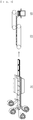
- FIG. 2 shows an example of the stacked/folded type electrode assembly.
- C-type bi-cells C in each of which a negative electrode, a separator, a positive electrode, a separator, and a negative electrode are sequentially stacked
- A-type bi-cells A in each of which a positive electrode, a separator, a negative electrode, a separator, and positive electrode are sequentially stacked, are separately manufactured.
- the C-type bi-cells C and the A-type bi-cells A are alternately overlapped on a separation film S having a continuous length.
- the separation film S is interposed between the overlap portions.
- the separation film S has a unit length sufficient to wrap the bi-cells.
- the separation film S is bent inwards at every unit length to have a structure capable of continuously wrapping the respective bi-cells from the central bi-cell to the outermost bi-cells.
- the separation film S is interposed between the overlap portions of the bi-cells.
- the distal end of the separation film S is finished by thermal fusion or using adhesive tape.
- Patent Document 1 Korean Patent Application Publication No. 2016-0094182
- the present invention has been made in view of the above problems, and it is an object of the present invention to provide a method of manufacturing an electrode assembly having a novel structure using mono-cells and an electrode assembly manufactured by the method.
- an electrode assembly manufacturing method which is a method of manufacturing an electrode assembly using mono-cells having an identical structure, each of the mono-cells including a first electrode, a separator, and a second electrode sequentially stacked on a separation film, the first electrode and the second electrode having opposite polarities, includes forming each of the mono-cells by sequentially stacking a respective one of the first electrodes, the separators, and the second electrodes on a separation film having a continuous length, each of the first electrodes, the separators, and the second electrodes being cut to a predetermined size from a winding roll so as to have a discontinuous structure, bonding each of the stacked mono-cells using a lamination device, disposing a bi-cell at a folding start part, from which folding starts, on the separation film, the bi-cell being spaced apart from the mono-cells by a distance for folding, and performing folding in one direction with the bi-cell as a beginning.
- the step of disposing the bi-cell may be performed immediately before the step of bonding each of the stacked mono-cells using the lamination device.
- the first electrode may be a positive electrode
- the second electrode may be a negative electrode
- the bi-cell may be an A-type bi-cell (positive electrode-separator-negative electrode-separator-positive electrode).
- the first electrode may be a negative electrode
- the second electrode may be a positive electrode
- the bi-cell may be a C-type bi-cell (negative electrode-separator-positive electrode-separator-negative electrode).
- the step of bonding each of the stacked mono-cells using the lamination device may be performed using one of: a method of applying pressure; or a method of simultaneously applying pressure and heat.
- the bi-cell may be separately manufactured and prepared.
- an electrode assembly includes a bi-cell located at a folding start part, from which folding starts, on a separation film having a continuous length and a plurality of mono-cells, each of the mono-cells including a first electrode, a separator, and a second electrode, each of the mono-cells being discontinuously located so as to be spaced apart from the bi-cell by a distance for folding, the first electrode, the separator, and the second electrode of each mono-cell being sequentially stacked, the first electrode and the second electrode of each mono-cell having opposite polarities, wherein the bi-cell and the mono-cells are folded in one direction with the bi-cell as a beginning.
- the first electrode may be a positive electrode
- the second electrode may be a negative electrode
- the bi-cell may be an A-type bi-cell (positive electrode-separator-negative electrode-separator-positive electrode).
- the first electrode may be a negative electrode
- the second electrode may be a positive electrode
- the bi-cell may be a C-type bi-cell (negative electrode-separator-positive electrode-separator-negative electrode).
- a secondary battery according to the present invention includes the electrode assembly described above.
- a battery pack according to the present invention includes the secondary battery described above.
- a method of manufacturing an electrode assembly according to the present invention has an advantage in that it is possible to immediately perform a folding process without a separate additional process after a lamination process, whereby it is possible to simplify an electrode assembly production process.
- FIG. 3 is a schematic view of an electrode assembly manufacturing apparatus 100 according to a first preferred embodiment of the present invention.
- a first electrode supplied from a first electrode winding roll 102 is located on a separation film S continuously supplied from a separation film winding roll 101 so as to have a discontinuous structure in the state of being cut to a predetermined size using a cutter 110.
- a separator supplied from a separator winding roll 103 is stacked on the first electrode in the state of being cut to a predetermined size using a cutter 110.
- a second electrode supplied from a second electrode winding roll 104 which has a polarity different from the polarity of the first electrode, is stacked on the separator in the state of being cut to a predetermined size using a cutter 110 to form a mono-cell M.
- the stacked mono-cell M is supplied to a lamination device 120. Using the lamination device 120, pressure is applied to the mono-cell, or pressure and heat are simultaneously supplied to the mono-cell, such that the electrodes and the separator are bonded to each other.
- discontinuous structure means that an electrode does not integrally extend without being cut and means that several individual electrodes having a predetermined size are separated from each other.
- a bi-cell B separately manufactured and prepared is located at a folding start part, from which folding starts, on the separation film S, on which bonded mono-cells are located, so as to be spaced apart from the mono-cell by a predetermined distance in consideration of a folding interval.
- folding is performed by a folding device 130 to manufacture an electrode assembly.
- the distal end of the separation film S is finished by thermal fusion or using adhesive tape.
- the step of locating the bi-cell B may be performed after the mono-cells pass through the lamination device 120, as described above, or after the mono-cells are stacked and before the stacked mono-cells enter the lamination device 120.
- FIGS. 4 and 5 are schematic views showing the structure of the electrode assembly before/after the folding process.
- the type of the bi-cell located at the folding start part, from which folding starts, on the separation film S varies depending on the kind of the first electrode of the mono-cell located on the separation film S in consideration of polarities of neighboring electrodes after the folding process.
- the first electrode is a positive electrode
- an A-type bi-cell A is located in the case in which the first electrode is a positive electrode
- a C-type bi-cell C is located in the case in which the first electrode is a negative electrode.
- the positive electrode may be manufactured, for example, by applying a mixture of a positive electrode active material, a conductive agent, and a binder to a positive electrode current collector and drying the mixture.
- a filler may be further added to the mixture as needed.
- the positive electrode active material is a material that is capable of inducing an electrochemical reaction.
- the positive electrode active material may be a lithium transition metal oxide including two or more transition metals.
- the conductive agent is generally added so that the conductive agent accounts for 1 to 20 weight% based on the total weight of the compound including the positive electrode active material.
- the conductive agent is not particularly restricted, as long as the conductive agent exhibits high conductivity without inducing any chemical change in a battery to which the conductive agent is applied.
- graphite such as natural graphite or artificial graphite
- carbon black such as carbon black, acetylene black, Ketjen black, channel black, furnace black, lamp black, or thermal black
- conductive fiber such as carbon fiber or metallic fiber
- metallic powder such as carbon fluoride powder, aluminum powder, or nickel powder
- conductive whisker such as zinc oxide or potassium titanate
- a conductive metal oxide such as titanium oxide
- a conductive material such as a polyphenylene derivative
- the filler is an optional component used to inhibit expansion of the positive electrode.
- the filler there is no particular limit to the filler, as long as the filler is made of a fibrous material while the filler does not cause chemical changes in a battery to which the filler is applied.
- the filler there may be used an olefin-based polymer, such as polyethylene or polypropylene; and a fibrous material, such as glass fiber or carbon fiber.
- the negative electrode may be manufactured, for example, by applying, drying, and pressing a negative electrode active material to a negative electrode current collector.
- the negative electrode mixture may selectively further include a conductive agent, a binder, and a filler as needed.
- the negative electrode current collector is not particularly restricted, as long as the negative electrode current collector exhibits high conductivity while the negative electrode current collector does not induce any chemical change in a battery to which the negative electrode current collector is applied.
- the negative electrode current collector may be made of copper, stainless steel, aluminum, nickel, titanium, or sintered carbon.
- the negative electrode current collector may be made of copper or stainless steel, the surface of which is treated with carbon, nickel, titanium, or silver, or an aluminum-cadmium alloy.
- the negative electrode current collector may have a micro-scale uneven pattern formed on the surface thereof so as to increase the force of adhesion of the negative electrode active material, in the same manner as the positive electrode current collector.
- the negative electrode current collector may be configured in any of various forms, such as a film, a sheet, a foil, a net, a porous body, a foam body, and a non-woven fabric body.
- the negative electrode active material for example, there may be used carbon, such as a non-graphitized carbon or a graphite-based carbon; a metal composite oxide, such as Li x Fe 2 O 3 (0 ⁇ x ⁇ 1), Li x WO 2 (0 ⁇ x ⁇ 1), or Sn x Me 1-x Me' y O z (Me: Mn, Fe, Pb, Ge; Me': Al, B, P, Si, Group 1, 2 and 3 elements of the periodic table, halogen; 0 ⁇ x ⁇ 1; 1 ⁇ y ⁇ 3; 1 ⁇ z ⁇ 8); lithium metal; lithium alloy; a silicon-based alloy; a tin-based alloy; a metal oxide, such as SnO, SnO 2 , PbO, PbO 2 , Pb 2 O 3 , Pb 3 O 4 , Sb 2 O 3 , Sb 2 O 4 , Sb 2 O 5 , GeO, GeO 2 , Bi 2 O 3 , Bi 2 O 4 , or Bi 2 O 5 ;
- the separator an insulative thin film that exhibits high ion permeability and mechanical strength is used.
- the separator generally has a pore diameter of 0.01 to 10 ⁇ m and a thickness of 5 to 300 ⁇ m.
- a sheet or non-woven fabric made of an olefin-based polymer, such as polypropylene, which exhibits chemical resistance and hydrophobicity, glass fiber, or polyethylene is used.
- a solid electrolyte such as a polymer
- the solid electrolyte may also function as the separator.
- a description of the separator is equally applicable to the separation film used in the present invention.
Abstract
Description
- This application claims the benefit of priority to
Korean Patent Application No. 2019-0141360 filed on November 7, 2019 - The present invention relates to a method of manufacturing an electrode assembly by folding mono-cells.
- With technological development of mobile devices, such as mobile phones, laptop computers, camcorders, and digital cameras, and an increase in the demand therefor, research on secondary batteries, which are capable of being charged and discharged, has been actively conducted. In addition, secondary batteries, which are energy sources substituting fossil fuels causing air pollution, have been applied to an electric vehicle (EV), a hybrid electric vehicle (HEV), and a plug-in hybrid electric vehicle (PHEV), and therefore there is increasing necessity for development of secondary batteries.
- Such a secondary battery has an electrode assembly mounted in a battery case. The electrode assembly is a power generation device configured to have a structure in which a positive electrode and a negative electrode are stacked in the state in which a separator is interposed therebetween. A jelly-roll type electrode assembly, a stacked type electrode assembly, and a stacked/folded type electrode assembly have been developed.
- The stacked/folded type electrode assembly has a structure in which mono-cells having a positive electrode/separator/negative electrode structure of a predetermined unit size or bi-cells having a positive electrode (negative electrode)/separator/negative electrode (positive electrode)/separator/positive electrode (negative electrode) structure of a predetermined unit size are folded using a long continuous separation film.
- Also, in order to improve processability of a conventional stacked type electrode assembly and to satisfy the demand for various secondary batteries, a laminated/stacked type electrode assembly, which has a structure in which unit cells, electrodes and separators of each of which are laminated with each other in the state of being alternately stacked, are stacked, has also been developed.
-
FIG. 1 shows an apparatus for manufacturing such an electrode assembly. The apparatus includes a basic unitbody manufacturing unit 10, atransfer unit 20, and analignment unit 30. Basic unit bodies are manufactured by the basic unitbody manufacturing unit 10. Subsequently, the basic unit bodies are shifted onto a transfer belt of thetransfer unit 20, and are moved along the transfer belt. - After shifted from the transfer belt to the
alignment unit 30, the basic unit bodies are sequentially uniformly aligned by thealignment unit 30, whereby a unit body stack may be manufactured. Subsequently, the unit body stack may be further subjected to a taping process of attaching a tape to the side of the unit body stack. When the taping process is completed, a complete electrode assembly may be manufactured (Korean Patent Application Publication No. 2016-0094182 - However, the apparatus of
FIG. 1 has a problem in that, after the basic unit bodies are manufactured, complicated processes of transferring the basic unit bodies and stacking the basic unit bodies on the alignment unit must be performed. - Meanwhile,
FIG. 2 shows an example of the stacked/folded type electrode assembly. C-type bi-cells C, in each of which a negative electrode, a separator, a positive electrode, a separator, and a negative electrode are sequentially stacked, and A-type bi-cells A, in each of which a positive electrode, a separator, a negative electrode, a separator, and positive electrode are sequentially stacked, are separately manufactured. Subsequently, the C-type bi-cells C and the A-type bi-cells A are alternately overlapped on a separation film S having a continuous length. The separation film S is interposed between the overlap portions. The separation film S has a unit length sufficient to wrap the bi-cells. The separation film S is bent inwards at every unit length to have a structure capable of continuously wrapping the respective bi-cells from the central bi-cell to the outermost bi-cells. The separation film S is interposed between the overlap portions of the bi-cells. The distal end of the separation film S is finished by thermal fusion or using adhesive tape. - However, there is a problem in that, in order to manufacture the electrode assembly of
FIG. 2 , two kinds of bi-cells must be separately manufactured and prepared, and then these bi-cells must be folded in the state of being arranged on the separation film S, which are complicated processes. - (Patent Document 1)
Korean Patent Application Publication No. 2016-0094182 - The present invention has been made in view of the above problems, and it is an object of the present invention to provide a method of manufacturing an electrode assembly having a novel structure using mono-cells and an electrode assembly manufactured by the method.
- In order to accomplish the above object, an electrode assembly manufacturing method according to the present invention, which is a method of manufacturing an electrode assembly using mono-cells having an identical structure, each of the mono-cells including a first electrode, a separator, and a second electrode sequentially stacked on a separation film, the first electrode and the second electrode having opposite polarities, includes forming each of the mono-cells by sequentially stacking a respective one of the first electrodes, the separators, and the second electrodes on a separation film having a continuous length, each of the first electrodes, the separators, and the second electrodes being cut to a predetermined size from a winding roll so as to have a discontinuous structure, bonding each of the stacked mono-cells using a lamination device, disposing a bi-cell at a folding start part, from which folding starts, on the separation film, the bi-cell being spaced apart from the mono-cells by a distance for folding, and performing folding in one direction with the bi-cell as a beginning.
- Also, in the electrode assembly manufacturing method according to the present invention, the step of disposing the bi-cell may be performed immediately before the step of bonding each of the stacked mono-cells using the lamination device.
- Also, in the electrode assembly manufacturing method according to the present invention, the first electrode may be a positive electrode, the second electrode may be a negative electrode, and the bi-cell may be an A-type bi-cell (positive electrode-separator-negative electrode-separator-positive electrode).
- Also, in the electrode assembly manufacturing method according to the present invention, the first electrode may be a negative electrode, the second electrode may be a positive electrode, and the bi-cell may be a C-type bi-cell (negative electrode-separator-positive electrode-separator-negative electrode).
- Also, in the electrode assembly manufacturing method according to the present invention, the step of bonding each of the stacked mono-cells using the lamination device may be performed using one of: a method of applying pressure; or a method of simultaneously applying pressure and heat.
- Also, in the electrode assembly manufacturing method according to the present invention, the bi-cell may be separately manufactured and prepared.
- In addition, an electrode assembly according to the present invention includes a bi-cell located at a folding start part, from which folding starts, on a separation film having a continuous length and a plurality of mono-cells, each of the mono-cells including a first electrode, a separator, and a second electrode, each of the mono-cells being discontinuously located so as to be spaced apart from the bi-cell by a distance for folding, the first electrode, the separator, and the second electrode of each mono-cell being sequentially stacked, the first electrode and the second electrode of each mono-cell having opposite polarities, wherein the bi-cell and the mono-cells are folded in one direction with the bi-cell as a beginning.
- Also, in the electrode assembly according to the present invention, the first electrode may be a positive electrode, the second electrode may be a negative electrode, and the bi-cell may be an A-type bi-cell (positive electrode-separator-negative electrode-separator-positive electrode).
- Also, in the electrode assembly according to the present invention, the first electrode may be a negative electrode, the second electrode may be a positive electrode, and the bi-cell may be a C-type bi-cell (negative electrode-separator-positive electrode-separator-negative electrode).
- In addition, a secondary battery according to the present invention includes the electrode assembly described above.
- In addition, a battery pack according to the present invention includes the secondary battery described above.
- A method of manufacturing an electrode assembly according to the present invention has an advantage in that it is possible to immediately perform a folding process without a separate additional process after a lamination process, whereby it is possible to simplify an electrode assembly production process.
-
-
FIG. 1 is a schematic view of a conventional electrode assembly manufacturing apparatus. -
FIG. 2 is a schematic view showing the structure of an electrode assembly manufactured using conventional bi-cells. -
FIG. 3 is a schematic view showing an embodiment of an electrode assembly manufacturing apparatus for manufacturing an electrode assembly according to the present invention. -
FIG. 4 is a schematic view showing an embodiment of the structure of an electrode assembly manufactured using a bi-cell according to the present invention. -
FIG. 5 is a schematic view showing another embodiment of the structure of the electrode assembly manufactured using the bi-cell according to the present invention. - In the present application, it should be understood that the terms "comprises," "has," "includes," etc. specify the presence of stated features, numbers, steps, operations, elements, components, or combinations thereof, but do not preclude the presence or addition of one or more other features, numbers, steps, operations, elements, components, or combinations thereof.
- In addition, the same reference numbers will be used throughout the drawings to refer to parts that perform similar functions or operations. In the case in which one part is said to be connected to another part in the specification, not only may the one part be directly connected to the other part, but also, the one part may be indirectly connected to the other part via a further part. In addition, that a certain element is included does not mean that other elements are excluded, but means that such elements may be further included unless mentioned otherwise.
- Hereinafter, an electrode assembly manufacturing method according to the present invention and an electrode assembly manufactured by the method will be described with reference to the accompanying drawings.
-
FIG. 3 is a schematic view of an electrodeassembly manufacturing apparatus 100 according to a first preferred embodiment of the present invention. - An electrode assembly manufacturing method will be described with reference to
FIG. 3 . First, a first electrode supplied from a firstelectrode winding roll 102 is located on a separation film S continuously supplied from a separationfilm winding roll 101 so as to have a discontinuous structure in the state of being cut to a predetermined size using acutter 110. Subsequently, a separator supplied from aseparator winding roll 103 is stacked on the first electrode in the state of being cut to a predetermined size using acutter 110. Subsequently, a second electrode supplied from a secondelectrode winding roll 104, which has a polarity different from the polarity of the first electrode, is stacked on the separator in the state of being cut to a predetermined size using acutter 110 to form a mono-cell M. Subsequently, the stacked mono-cell M is supplied to alamination device 120. Using thelamination device 120, pressure is applied to the mono-cell, or pressure and heat are simultaneously supplied to the mono-cell, such that the electrodes and the separator are bonded to each other. - Here, the "discontinuous structure" means that an electrode does not integrally extend without being cut and means that several individual electrodes having a predetermined size are separated from each other.
- Subsequently, a bi-cell B separately manufactured and prepared is located at a folding start part, from which folding starts, on the separation film S, on which bonded mono-cells are located, so as to be spaced apart from the mono-cell by a predetermined distance in consideration of a folding interval. Subsequently, folding is performed by a
folding device 130 to manufacture an electrode assembly. The distal end of the separation film S is finished by thermal fusion or using adhesive tape. - Meanwhile, the step of locating the bi-cell B may be performed after the mono-cells pass through the
lamination device 120, as described above, or after the mono-cells are stacked and before the stacked mono-cells enter thelamination device 120. -
FIGS. 4 and 5 are schematic views showing the structure of the electrode assembly before/after the folding process. - Referring to
FIGS. 4 and 5 , the type of the bi-cell located at the folding start part, from which folding starts, on the separation film S varies depending on the kind of the first electrode of the mono-cell located on the separation film S in consideration of polarities of neighboring electrodes after the folding process. In the case in which the first electrode is a positive electrode, as shown inFIG. 4 , an A-type bi-cell A is located. In the case in which the first electrode is a negative electrode, as shown inFIG. 5 , a C-type bi-cell C is located. - The positive electrode may be manufactured, for example, by applying a mixture of a positive electrode active material, a conductive agent, and a binder to a positive electrode current collector and drying the mixture. A filler may be further added to the mixture as needed.
- The positive electrode active material is a material that is capable of inducing an electrochemical reaction. The positive electrode active material may be a lithium transition metal oxide including two or more transition metals. For example, the positive electrode active material may be, but is not limited to, a layered compound, such as lithium cobalt oxide (LiCoO2) or lithium nickel oxide (LiNiO2) substituted with one or more transition metals; lithium manganese oxide substituted with one or more transition metals; a lithium nickel-based oxide represented by the chemical formula LiNi1-yMyO2 (where M = Co, Mn, Al, Cu, Fe, Mg, B, Cr, Zn, or Ga, at least one of which is included, and 0.01≤y≤0.7);
- a lithium nickel cobalt manganese composite oxide represented by the chemical formula Li1+zNibMncCo1-(b+c+d)MdO(2-e)Ae (where -0.5≤z≤0.5, 0.1≤b≤0.8, 0.1≤c≤0.8, 0≤d≤0.2, 0≤e≤0.2, b+c+d<1, M = Al, Mg, Cr, Ti, Si, or Y, and A = F, P, or Cl), such as Li1+zNi1/3Co1/3Mn1/3O2 or Li1+zNi0.4Mn0.4Co0.2O2; or an olivine-based lithium metal phosphate represented by the chemical formula Li1+xM1-yM'yPO4-zXz (where M = a transition metal, preferably Fe, Mn, Co, or Ni, M' = Al, Mg, or Ti, X = F, S, or N, - 0.5≤x≤+0.5, 0≤y≤0.5, and 0≤z≤0.1).
- The conductive agent is generally added so that the conductive agent accounts for 1 to 20 weight% based on the total weight of the compound including the positive electrode active material. The conductive agent is not particularly restricted, as long as the conductive agent exhibits high conductivity without inducing any chemical change in a battery to which the conductive agent is applied. For example, graphite, such as natural graphite or artificial graphite; carbon black, such as carbon black, acetylene black, Ketjen black, channel black, furnace black, lamp black, or thermal black; conductive fiber, such as carbon fiber or metallic fiber; metallic powder, such as carbon fluoride powder, aluminum powder, or nickel powder; conductive whisker, such as zinc oxide or potassium titanate; a conductive metal oxide, such as titanium oxide; or a conductive material, such as a polyphenylene derivative, may be used as the conductive agent.
- The filler is an optional component used to inhibit expansion of the positive electrode. There is no particular limit to the filler, as long as the filler is made of a fibrous material while the filler does not cause chemical changes in a battery to which the filler is applied. As examples of the filler, there may be used an olefin-based polymer, such as polyethylene or polypropylene; and a fibrous material, such as glass fiber or carbon fiber.
- In addition, the negative electrode may be manufactured, for example, by applying, drying, and pressing a negative electrode active material to a negative electrode current collector. The negative electrode mixture may selectively further include a conductive agent, a binder, and a filler as needed. The negative electrode current collector is not particularly restricted, as long as the negative electrode current collector exhibits high conductivity while the negative electrode current collector does not induce any chemical change in a battery to which the negative electrode current collector is applied. For example, the negative electrode current collector may be made of copper, stainless steel, aluminum, nickel, titanium, or sintered carbon. Alternatively, the negative electrode current collector may be made of copper or stainless steel, the surface of which is treated with carbon, nickel, titanium, or silver, or an aluminum-cadmium alloy. In addition, the negative electrode current collector may have a micro-scale uneven pattern formed on the surface thereof so as to increase the force of adhesion of the negative electrode active material, in the same manner as the positive electrode current collector. The negative electrode current collector may be configured in any of various forms, such as a film, a sheet, a foil, a net, a porous body, a foam body, and a non-woven fabric body. As the negative electrode active material, for example, there may be used carbon, such as a non-graphitized carbon or a graphite-based carbon; a metal composite oxide, such as LixFe2O3 (0≤x≤1), LixWO2 (0≤x≤1), or SnxMe1-xMe'yOz (Me: Mn, Fe, Pb, Ge; Me': Al, B, P, Si, Group 1, 2 and 3 elements of the periodic table, halogen; 0<x≤1; 1≤y≤3; 1≤z≤8); lithium metal; lithium alloy; a silicon-based alloy; a tin-based alloy; a metal oxide, such as SnO, SnO2, PbO, PbO2, Pb2O3, Pb3O4, Sb2O3, Sb2O4, Sb2O5, GeO, GeO2, Bi2O3, Bi2O4, or Bi2O5; a conductive polymer, such as polyacetylene; or a Li-Co-Ni based material.
- As the separator, an insulative thin film that exhibits high ion permeability and mechanical strength is used. The separator generally has a pore diameter of 0.01 to 10 µm and a thickness of 5 to 300 µm. As the material for the separator, for example, a sheet or non-woven fabric made of an olefin-based polymer, such as polypropylene, which exhibits chemical resistance and hydrophobicity, glass fiber, or polyethylene is used. In the case in which a solid electrolyte, such as a polymer, is used as an electrolyte, the solid electrolyte may also function as the separator. A description of the separator is equally applicable to the separation film used in the present invention.
- Although the present invention has been described in detail, those skilled in the art will appreciate that the detailed description thereof discloses only preferred embodiments of the present invention and thus does not limit the scope of the present invention. Accordingly, those skilled in the art will appreciate that various changes and modifications are possible, without departing from the category and technical idea of the present invention, and it will be obvious that such changes and modifications fall within the scope of the appended claims.
-
- 10:
- Basic unit body manufacturing unit
- 20:
- Transfer unit
- 30:
- Alignment unit
- A:
- A-type bi-cell
- C:
- C-type bi-cell
- S:
- Separation film
- M:
- Mono-cell
- B:
- Bi-cell
- 100:
- Electrode assembly manufacturing apparatus
- 101:
- Separation film winding roll
- 102:
- First electrode winding roll
- 103:
- Separator winding roll
- 104:
- Second electrode winding roll
- 110:
- Cutter
- 120:
- Lamination device
- 130:
- Folding device
Claims (11)
- A method of manufacturing an electrode assembly using mono-cells having an identical structure, each of the mono-cells comprising a first electrode, a separator, and a second electrode sequentially stacked on a separation film, the first electrode and the second electrode having opposite polarities, the method comprising:forming each of the mono-cells by sequentially stacking a respective one of the first electrodes, a respective one of the separators, and a respective one of the second electrodes on a separation film having a continuous length, each of the first electrodes, the separators, and the second electrodes being cut to a predetermined size from a winding roll so as to have a discontinuous structure;bonding each of the stacked mono-cells using a lamination device;disposing a bi-cell at a folding start part, from which folding starts, on the separation film, the bi-cell being spaced apart from the mono-cells by a distance for folding; andperforming folding in one direction with the bi-cell as a beginning.
- The method according to claim 1, wherein the step of disposing the bi-cell is performed immediately before the step of bonding each of the stacked mono-cells using the lamination device.
- The method according to claim 1 or 2, wherein the first electrode is a positive electrode, the second electrode is a negative electrode, and the bi-cell is an A-type bi-cell.
- The method according to claim 1 or 2, wherein the first electrode is a negative electrode, the second electrode is a positive electrode, and the bi-cell is a C-type bi-cell.
- The method according to claim 1 or 2, wherein the step of bonding each of the stacked mono-cells using the lamination device is performed using one of: a method of applying pressure; or a method of simultaneously applying pressure and heat.
- The method according to claim 1 or 2, wherein the bi-cell is separately manufactured and prepared.
- An electrode assembly comprising:a bi-cell located at a folding start part, from which folding starts, on a separation film having a continuous length; anda plurality of mono-cells, each of the mono-cells comprising a first electrode, a separator, and a second electrode, each of the mono-cells being discontinuously located so as to be spaced apart from the bi-cell by a distance for folding, the first electrode, the separator, and the second electrode of each mono-cell being sequentially stacked, the first electrode and the second electrode of each mono-cell having opposite polarities, whereinthe bi-cell and the mono-cells are folded in one direction with the bi-cell as a beginning.
- The electrode assembly according to claim 7, wherein the first electrode is a positive electrode, the second electrode is a negative electrode, and the bi-cell is an A-type bi-cell.
- The electrode assembly according to claim 7, wherein the first electrode is a negative electrode, the second electrode is a positive electrode, and the bi-cell is a C-type bi-cell.
- A secondary battery comprising the electrode assembly according to any one of claims 7 to 9.
- A battery pack comprising the secondary battery according to claim 10.
Applications Claiming Priority (2)
| Application Number | Priority Date | Filing Date | Title |
|---|---|---|---|
| KR1020190141360A KR20210055186A (en) | 2019-11-07 | 2019-11-07 | Folding type Electrode assembly and method for fabricating the same |
| PCT/KR2020/011029 WO2021091057A1 (en) | 2019-11-07 | 2020-08-19 | Folding electrode assembly and method for manufacturing same |
Publications (2)
| Publication Number | Publication Date |
|---|---|
| EP3890087A1 true EP3890087A1 (en) | 2021-10-06 |
| EP3890087A4 EP3890087A4 (en) | 2022-03-23 |
Family
ID=75849772
Family Applications (1)
| Application Number | Title | Priority Date | Filing Date |
|---|---|---|---|
| EP20885076.8A Pending EP3890087A4 (en) | 2019-11-07 | 2020-08-19 | Folding electrode assembly and method for manufacturing same |
Country Status (5)
| Country | Link |
|---|---|
| US (1) | US20220149422A1 (en) |
| EP (1) | EP3890087A4 (en) |
| KR (1) | KR20210055186A (en) |
| CN (1) | CN113875061A (en) |
| WO (1) | WO2021091057A1 (en) |
Families Citing this family (4)
| Publication number | Priority date | Publication date | Assignee | Title |
|---|---|---|---|---|
| KR20230020087A (en) | 2021-08-03 | 2023-02-10 | 주식회사 엘지에너지솔루션 | Unit cell aligning device and method |
| KR20230033443A (en) | 2021-09-01 | 2023-03-08 | 주식회사 엘지에너지솔루션 | Unit cell aligning device and method |
| KR20230137762A (en) | 2022-03-22 | 2023-10-05 | 주식회사 엘지에너지솔루션 | Unit battert cell manufactureing apparatus and method |
| KR20240044892A (en) | 2022-09-29 | 2024-04-05 | 고무균 | System for Manufacturing Electrode Cell of Secondary Battery |
Family Cites Families (11)
| Publication number | Priority date | Publication date | Assignee | Title |
|---|---|---|---|---|
| KR101150265B1 (en) * | 2007-07-16 | 2012-06-12 | 주식회사 엘지화학 | Stack/folding-typed electrode assembly of noble structure and method for preparation of the same |
| KR101361675B1 (en) * | 2011-03-31 | 2014-02-12 | 주식회사 엘지화학 | Method for Manufacturing Electrode Assembly and Electrode Assembly Manufactured Thereby |
| KR101332282B1 (en) * | 2012-03-14 | 2013-11-22 | 주식회사 엘지화학 | Electrode Assembly of Novel Structure and Battery Cell Comprising the Same |
| KR20140006722A (en) * | 2012-07-06 | 2014-01-16 | 주식회사 엘지화학 | Method for preparing secondary battery, secondary battery prepared by the method and electrochemical cell containing the same |
| KR101567629B1 (en) * | 2012-11-12 | 2015-11-10 | 주식회사 엘지화학 | An Symmetric Electrode Assembly, a Secondary Battery, a Battery Pack and a Device comprising the Same |
| KR101595643B1 (en) * | 2013-02-15 | 2016-02-18 | 주식회사 엘지화학 | Electrode assembly and cell of polymer lithium secondary battery comprising the same |
| KR101643593B1 (en) * | 2013-09-06 | 2016-07-29 | 주식회사 엘지화학 | Stack and Folding-Typed Electrode Assembly Having Improved Electrolyte Wetting Property and Method of Preparation of the Same |
| KR101795830B1 (en) * | 2013-12-09 | 2017-12-01 | 주식회사 엘지화학 | A Lamination and Stacking Apparatus and a Method thereof |
| KR101848542B1 (en) | 2015-01-30 | 2018-04-12 | 주식회사 엘지화학 | Device for manufacturing an electrode assembly |
| IT201700103755A1 (en) * | 2017-09-15 | 2019-03-15 | Manz Italy Srl | METHOD AND APPARATUS FOR ASSEMBLING ELECTRODES |
| KR20190141360A (en) | 2018-06-14 | 2019-12-24 | 최원준 | Smart ashtray with air purification |
-
2019
- 2019-11-07 KR KR1020190141360A patent/KR20210055186A/en not_active IP Right Cessation
-
2020
- 2020-08-19 WO PCT/KR2020/011029 patent/WO2021091057A1/en unknown
- 2020-08-19 CN CN202080037334.XA patent/CN113875061A/en active Pending
- 2020-08-19 US US17/429,828 patent/US20220149422A1/en active Pending
- 2020-08-19 EP EP20885076.8A patent/EP3890087A4/en active Pending
Also Published As
| Publication number | Publication date |
|---|---|
| CN113875061A (en) | 2021-12-31 |
| WO2021091057A1 (en) | 2021-05-14 |
| KR20210055186A (en) | 2021-05-17 |
| US20220149422A1 (en) | 2022-05-12 |
| EP3890087A4 (en) | 2022-03-23 |
Similar Documents
| Publication | Publication Date | Title |
|---|---|---|
| US11081682B2 (en) | Fabricating method of electrode assembly and electrochemical cell containing the same | |
| US10763534B2 (en) | Electrode assembly and electrochemical cell including the same | |
| EP3890087A1 (en) | Folding electrode assembly and method for manufacturing same | |
| JP5425803B2 (en) | Electrode assembly and manufacturing method thereof, secondary battery, middle- or large-sized battery module | |
| KR101150265B1 (en) | Stack/folding-typed electrode assembly of noble structure and method for preparation of the same | |
| US10516185B2 (en) | Electrode assembly and electrochemical cell containing the same | |
| JP5697276B2 (en) | Electrode assembly having novel structure and method of manufacturing the same | |
| EP2869387A1 (en) | Electrode assembly and method for manufacturing same | |
| EP2869385B1 (en) | Electrode assembly, fabricating method of the electrode assembly, and electrochemial cell containing the electrode assembly | |
| EP2757625B1 (en) | Method for manufacturing electrode assembly and electrochemical device | |
| KR101431278B1 (en) | Secondary battery having enhanced uniformity of temperature distribution | |
| CN108335915B (en) | Method of manufacturing electrode assembly and electrochemical cell including the same | |
| KR102042999B1 (en) | Method for Preparation of Stack and Folding-typed Electrode Assembly Having Electrode Taps with Various-Sized | |
| KR20140034340A (en) | Electrode assembly and electrochemical cell containing the same, and cell moudle with the same | |
| KR20230112083A (en) | Electrode assembly with short circuit prevention structure | |
| KR20230106397A (en) | Electrode tab welding method of electrode assembly and manufacturing method of secondary battery | |
| KR20230171748A (en) | Sub-roller for laminating unit cell and folding separater in stack-folding process and laminating appratus using the same |
Legal Events
| Date | Code | Title | Description |
|---|---|---|---|
| STAA | Information on the status of an ep patent application or granted ep patent |
Free format text: STATUS: THE INTERNATIONAL PUBLICATION HAS BEEN MADE |
|
| PUAI | Public reference made under article 153(3) epc to a published international application that has entered the european phase |
Free format text: ORIGINAL CODE: 0009012 |
|
| STAA | Information on the status of an ep patent application or granted ep patent |
Free format text: STATUS: REQUEST FOR EXAMINATION WAS MADE |
|
| 17P | Request for examination filed |
Effective date: 20210629 |
|
| AK | Designated contracting states |
Kind code of ref document: A1 Designated state(s): AL AT BE BG CH CY CZ DE DK EE ES FI FR GB GR HR HU IE IS IT LI LT LU LV MC MK MT NL NO PL PT RO RS SE SI SK SM TR |
|
| A4 | Supplementary search report drawn up and despatched |
Effective date: 20220221 |
|
| RIC1 | Information provided on ipc code assigned before grant |
Ipc: H01M 10/0525 20100101ALI20220215BHEP Ipc: H01M 10/0583 20100101ALI20220215BHEP Ipc: H01M 10/04 20060101AFI20220215BHEP |
|
| RAP3 | Party data changed (applicant data changed or rights of an application transferred) |
Owner name: LG ENERGY SOLUTION, LTD. |
|
| DAV | Request for validation of the european patent (deleted) | ||
| DAX | Request for extension of the european patent (deleted) |