US10763534B2 - Electrode assembly and electrochemical cell including the same - Google Patents
Electrode assembly and electrochemical cell including the same Download PDFInfo
- Publication number
- US10763534B2 US10763534B2 US15/861,233 US201815861233A US10763534B2 US 10763534 B2 US10763534 B2 US 10763534B2 US 201815861233 A US201815861233 A US 201815861233A US 10763534 B2 US10763534 B2 US 10763534B2
- Authority
- US
- United States
- Prior art keywords
- electrode
- separator
- stack part
- electrode assembly
- stacking
- Prior art date
- Legal status (The legal status is an assumption and is not a legal conclusion. Google has not performed a legal analysis and makes no representation as to the accuracy of the status listed.)
- Active, expires
Links
- 239000000463 material Substances 0.000 claims description 51
- 239000011248 coating agent Substances 0.000 claims description 22
- 238000000576 coating method Methods 0.000 claims description 22
- 239000007772 electrode material Substances 0.000 claims description 18
- 229920000642 polymer Polymers 0.000 claims description 12
- 239000011230 binding agent Substances 0.000 claims description 9
- 238000003466 welding Methods 0.000 claims description 9
- 239000010954 inorganic particle Substances 0.000 claims description 8
- 239000000203 mixture Substances 0.000 claims description 8
- 238000007789 sealing Methods 0.000 claims description 8
- 230000008602 contraction Effects 0.000 claims description 3
- 238000000034 method Methods 0.000 abstract description 42
- 230000008569 process Effects 0.000 abstract description 34
- OKTJSMMVPCPJKN-UHFFFAOYSA-N Carbon Chemical compound [C] OKTJSMMVPCPJKN-UHFFFAOYSA-N 0.000 description 14
- -1 LiV3O8 Chemical compound 0.000 description 14
- PXHVJJICTQNCMI-UHFFFAOYSA-N Nickel Chemical compound [Ni] PXHVJJICTQNCMI-UHFFFAOYSA-N 0.000 description 12
- 238000010030 laminating Methods 0.000 description 12
- 239000000126 substance Substances 0.000 description 7
- 239000004698 Polyethylene Substances 0.000 description 6
- 239000004743 Polypropylene Substances 0.000 description 6
- 229910052799 carbon Inorganic materials 0.000 description 6
- 239000006182 cathode active material Substances 0.000 description 6
- 239000004020 conductor Substances 0.000 description 6
- 239000010408 film Substances 0.000 description 6
- 238000004519 manufacturing process Methods 0.000 description 6
- 229910052759 nickel Inorganic materials 0.000 description 6
- 229910052782 aluminium Inorganic materials 0.000 description 5
- 238000007689 inspection Methods 0.000 description 5
- 229910052744 lithium Inorganic materials 0.000 description 5
- 239000004745 nonwoven fabric Substances 0.000 description 5
- WHXSMMKQMYFTQS-UHFFFAOYSA-N Lithium Chemical compound [Li] WHXSMMKQMYFTQS-UHFFFAOYSA-N 0.000 description 4
- RTAQQCXQSZGOHL-UHFFFAOYSA-N Titanium Chemical compound [Ti] RTAQQCXQSZGOHL-UHFFFAOYSA-N 0.000 description 4
- XAGFODPZIPBFFR-UHFFFAOYSA-N aluminium Chemical compound [Al] XAGFODPZIPBFFR-UHFFFAOYSA-N 0.000 description 4
- 239000006183 anode active material Substances 0.000 description 4
- 230000008859 change Effects 0.000 description 4
- 229910052802 copper Inorganic materials 0.000 description 4
- 239000010949 copper Substances 0.000 description 4
- 239000000835 fiber Substances 0.000 description 4
- 230000001939 inductive effect Effects 0.000 description 4
- 229910052742 iron Inorganic materials 0.000 description 4
- 229920000573 polyethylene Polymers 0.000 description 4
- 229920001155 polypropylene Polymers 0.000 description 4
- 229910001220 stainless steel Inorganic materials 0.000 description 4
- 239000010935 stainless steel Substances 0.000 description 4
- 229910052719 titanium Inorganic materials 0.000 description 4
- 239000010936 titanium Substances 0.000 description 4
- 230000003247 decreasing effect Effects 0.000 description 3
- 238000010586 diagram Methods 0.000 description 3
- 239000000945 filler Substances 0.000 description 3
- 150000002500 ions Chemical class 0.000 description 3
- 229920000049 Carbon (fiber) Polymers 0.000 description 2
- RYGMFSIKBFXOCR-UHFFFAOYSA-N Copper Chemical compound [Cu] RYGMFSIKBFXOCR-UHFFFAOYSA-N 0.000 description 2
- BQCADISMDOOEFD-UHFFFAOYSA-N Silver Chemical compound [Ag] BQCADISMDOOEFD-UHFFFAOYSA-N 0.000 description 2
- 150000001336 alkenes Chemical class 0.000 description 2
- 229910045601 alloy Inorganic materials 0.000 description 2
- 239000000956 alloy Substances 0.000 description 2
- WMWLMWRWZQELOS-UHFFFAOYSA-N bismuth(iii) oxide Chemical compound O=[Bi]O[Bi]=O WMWLMWRWZQELOS-UHFFFAOYSA-N 0.000 description 2
- 229910052796 boron Inorganic materials 0.000 description 2
- 239000003990 capacitor Substances 0.000 description 2
- 239000004917 carbon fiber Substances 0.000 description 2
- 150000001875 compounds Chemical class 0.000 description 2
- 238000005520 cutting process Methods 0.000 description 2
- GNTDGMZSJNCJKK-UHFFFAOYSA-N divanadium pentaoxide Chemical compound O=[V](=O)O[V](=O)=O GNTDGMZSJNCJKK-UHFFFAOYSA-N 0.000 description 2
- 238000001035 drying Methods 0.000 description 2
- 238000004049 embossing Methods 0.000 description 2
- 239000011888 foil Substances 0.000 description 2
- YBMRDBCBODYGJE-UHFFFAOYSA-N germanium dioxide Chemical compound O=[Ge]=O YBMRDBCBODYGJE-UHFFFAOYSA-N 0.000 description 2
- 239000003365 glass fiber Substances 0.000 description 2
- 229910002804 graphite Inorganic materials 0.000 description 2
- 239000010439 graphite Substances 0.000 description 2
- 229910000625 lithium cobalt oxide Inorganic materials 0.000 description 2
- BFZPBUKRYWOWDV-UHFFFAOYSA-N lithium;oxido(oxo)cobalt Chemical compound [Li+].[O-][Co]=O BFZPBUKRYWOWDV-UHFFFAOYSA-N 0.000 description 2
- 229910052748 manganese Inorganic materials 0.000 description 2
- 239000011572 manganese Substances 0.000 description 2
- 229910052751 metal Inorganic materials 0.000 description 2
- 239000002184 metal Substances 0.000 description 2
- 229910044991 metal oxide Inorganic materials 0.000 description 2
- 150000004706 metal oxides Chemical class 0.000 description 2
- VNWKTOKETHGBQD-UHFFFAOYSA-N methane Chemical compound C VNWKTOKETHGBQD-UHFFFAOYSA-N 0.000 description 2
- JRZJOMJEPLMPRA-UHFFFAOYSA-N olefin Natural products CCCCCCCC=C JRZJOMJEPLMPRA-UHFFFAOYSA-N 0.000 description 2
- 239000005518 polymer electrolyte Substances 0.000 description 2
- 239000011148 porous material Substances 0.000 description 2
- 239000000843 powder Substances 0.000 description 2
- 238000003825 pressing Methods 0.000 description 2
- 229910052710 silicon Inorganic materials 0.000 description 2
- 229910052709 silver Inorganic materials 0.000 description 2
- 239000004332 silver Substances 0.000 description 2
- 239000007784 solid electrolyte Substances 0.000 description 2
- XOLBLPGZBRYERU-UHFFFAOYSA-N tin dioxide Chemical compound O=[Sn]=O XOLBLPGZBRYERU-UHFFFAOYSA-N 0.000 description 2
- 229910052725 zinc Inorganic materials 0.000 description 2
- 229920002134 Carboxymethyl cellulose Polymers 0.000 description 1
- 229910000925 Cd alloy Inorganic materials 0.000 description 1
- 229910018039 Cu2V2O7 Inorganic materials 0.000 description 1
- 229910017010 Fe2 (MoO4)3 Inorganic materials 0.000 description 1
- YCKRFDGAMUMZLT-UHFFFAOYSA-N Fluorine atom Chemical compound [F] YCKRFDGAMUMZLT-UHFFFAOYSA-N 0.000 description 1
- 229920002153 Hydroxypropyl cellulose Polymers 0.000 description 1
- 229910000733 Li alloy Inorganic materials 0.000 description 1
- 229910007969 Li-Co-Ni Inorganic materials 0.000 description 1
- 229910006570 Li1+xMn2-xO4 Inorganic materials 0.000 description 1
- 229910006628 Li1+xMn2−xO4 Inorganic materials 0.000 description 1
- 229910010228 Li2Mn3MO8 Inorganic materials 0.000 description 1
- 229910010521 LiFe3O4 Inorganic materials 0.000 description 1
- 229910014172 LiMn2-xMxO2 Inorganic materials 0.000 description 1
- 229910014774 LiMn2O3 Inorganic materials 0.000 description 1
- 229910014437 LiMn2−XMXO2 Inorganic materials 0.000 description 1
- 229910002993 LiMnO2 Inorganic materials 0.000 description 1
- 229910014713 LiMnO3 Inorganic materials 0.000 description 1
- 229910014114 LiNi1-xMxO2 Inorganic materials 0.000 description 1
- 229910014907 LiNi1−xMxO2 Inorganic materials 0.000 description 1
- 229910012970 LiV3O8 Inorganic materials 0.000 description 1
- 229910002097 Lithium manganese(III,IV) oxide Inorganic materials 0.000 description 1
- 229910016622 LixFe2O3 Inorganic materials 0.000 description 1
- 229910015103 LixWO2 Inorganic materials 0.000 description 1
- 229910006555 Li—Co—Ni Inorganic materials 0.000 description 1
- 239000002033 PVDF binder Substances 0.000 description 1
- 229920003171 Poly (ethylene oxide) Polymers 0.000 description 1
- 229920000265 Polyparaphenylene Polymers 0.000 description 1
- 239000004372 Polyvinyl alcohol Substances 0.000 description 1
- XUIMIQQOPSSXEZ-UHFFFAOYSA-N Silicon Chemical compound [Si] XUIMIQQOPSSXEZ-UHFFFAOYSA-N 0.000 description 1
- 229920002472 Starch Polymers 0.000 description 1
- ATJFFYVFTNAWJD-UHFFFAOYSA-N Tin Chemical compound [Sn] ATJFFYVFTNAWJD-UHFFFAOYSA-N 0.000 description 1
- GWEVSGVZZGPLCZ-UHFFFAOYSA-N Titan oxide Chemical compound O=[Ti]=O GWEVSGVZZGPLCZ-UHFFFAOYSA-N 0.000 description 1
- QDDVNKWVBSLTMB-UHFFFAOYSA-N [Cu]=O.[Li] Chemical compound [Cu]=O.[Li] QDDVNKWVBSLTMB-UHFFFAOYSA-N 0.000 description 1
- XHCLAFWTIXFWPH-UHFFFAOYSA-N [O-2].[O-2].[O-2].[O-2].[O-2].[V+5].[V+5] Chemical compound [O-2].[O-2].[O-2].[O-2].[O-2].[V+5].[V+5] XHCLAFWTIXFWPH-UHFFFAOYSA-N 0.000 description 1
- 239000006230 acetylene black Substances 0.000 description 1
- 239000011149 active material Substances 0.000 description 1
- 229910001420 alkaline earth metal ion Inorganic materials 0.000 description 1
- HSFWRNGVRCDJHI-UHFFFAOYSA-N alpha-acetylene Natural products C#C HSFWRNGVRCDJHI-UHFFFAOYSA-N 0.000 description 1
- LJCFOYOSGPHIOO-UHFFFAOYSA-N antimony pentoxide Inorganic materials O=[Sb](=O)O[Sb](=O)=O LJCFOYOSGPHIOO-UHFFFAOYSA-N 0.000 description 1
- 229910000411 antimony tetroxide Inorganic materials 0.000 description 1
- GHPGOEFPKIHBNM-UHFFFAOYSA-N antimony(3+);oxygen(2-) Chemical compound [O-2].[O-2].[O-2].[Sb+3].[Sb+3] GHPGOEFPKIHBNM-UHFFFAOYSA-N 0.000 description 1
- 229910021383 artificial graphite Inorganic materials 0.000 description 1
- 230000000712 assembly Effects 0.000 description 1
- 238000000429 assembly Methods 0.000 description 1
- 229910000417 bismuth pentoxide Inorganic materials 0.000 description 1
- 239000006229 carbon black Substances 0.000 description 1
- 239000006231 channel black Substances 0.000 description 1
- 229910052804 chromium Inorganic materials 0.000 description 1
- 229920001940 conductive polymer Polymers 0.000 description 1
- 150000004696 coordination complex Chemical class 0.000 description 1
- 229920001577 copolymer Polymers 0.000 description 1
- 230000007547 defect Effects 0.000 description 1
- NJLLQSBAHIKGKF-UHFFFAOYSA-N dipotassium dioxido(oxo)titanium Chemical compound [K+].[K+].[O-][Ti]([O-])=O NJLLQSBAHIKGKF-UHFFFAOYSA-N 0.000 description 1
- 229920001971 elastomer Polymers 0.000 description 1
- 230000005611 electricity Effects 0.000 description 1
- 238000003487 electrochemical reaction Methods 0.000 description 1
- 238000005868 electrolysis reaction Methods 0.000 description 1
- 239000003792 electrolyte Substances 0.000 description 1
- 125000002573 ethenylidene group Chemical group [*]=C=C([H])[H] 0.000 description 1
- 229910052731 fluorine Inorganic materials 0.000 description 1
- 239000011737 fluorine Substances 0.000 description 1
- 239000000446 fuel Substances 0.000 description 1
- 239000006232 furnace black Substances 0.000 description 1
- 229910052733 gallium Inorganic materials 0.000 description 1
- 229910052732 germanium Inorganic materials 0.000 description 1
- PVADDRMAFCOOPC-UHFFFAOYSA-N germanium monoxide Inorganic materials [Ge]=O PVADDRMAFCOOPC-UHFFFAOYSA-N 0.000 description 1
- 229910052736 halogen Inorganic materials 0.000 description 1
- 150000002367 halogens Chemical class 0.000 description 1
- 238000010438 heat treatment Methods 0.000 description 1
- 230000002209 hydrophobic effect Effects 0.000 description 1
- 239000001863 hydroxypropyl cellulose Substances 0.000 description 1
- 235000010977 hydroxypropyl cellulose Nutrition 0.000 description 1
- 239000003273 ketjen black Substances 0.000 description 1
- 238000003475 lamination Methods 0.000 description 1
- 239000006233 lamp black Substances 0.000 description 1
- 229910052745 lead Inorganic materials 0.000 description 1
- YADSGOSSYOOKMP-UHFFFAOYSA-N lead dioxide Inorganic materials O=[Pb]=O YADSGOSSYOOKMP-UHFFFAOYSA-N 0.000 description 1
- YEXPOXQUZXUXJW-UHFFFAOYSA-N lead(II) oxide Inorganic materials [Pb]=O YEXPOXQUZXUXJW-UHFFFAOYSA-N 0.000 description 1
- XMFOQHDPRMAJNU-UHFFFAOYSA-N lead(II,IV) oxide Inorganic materials O1[Pb]O[Pb]11O[Pb]O1 XMFOQHDPRMAJNU-UHFFFAOYSA-N 0.000 description 1
- 239000001989 lithium alloy Substances 0.000 description 1
- 229910021445 lithium manganese complex oxide Inorganic materials 0.000 description 1
- 229910002102 lithium manganese oxide Inorganic materials 0.000 description 1
- VROAXDSNYPAOBJ-UHFFFAOYSA-N lithium;oxido(oxo)nickel Chemical compound [Li+].[O-][Ni]=O VROAXDSNYPAOBJ-UHFFFAOYSA-N 0.000 description 1
- VLXXBCXTUVRROQ-UHFFFAOYSA-N lithium;oxido-oxo-(oxomanganiooxy)manganese Chemical compound [Li+].[O-][Mn](=O)O[Mn]=O VLXXBCXTUVRROQ-UHFFFAOYSA-N 0.000 description 1
- URIIGZKXFBNRAU-UHFFFAOYSA-N lithium;oxonickel Chemical compound [Li].[Ni]=O URIIGZKXFBNRAU-UHFFFAOYSA-N 0.000 description 1
- 229910052749 magnesium Inorganic materials 0.000 description 1
- 230000004048 modification Effects 0.000 description 1
- 238000012986 modification Methods 0.000 description 1
- 229910021382 natural graphite Inorganic materials 0.000 description 1
- 229910021470 non-graphitizable carbon Inorganic materials 0.000 description 1
- 230000000737 periodic effect Effects 0.000 description 1
- 229910052698 phosphorus Inorganic materials 0.000 description 1
- 229920005569 poly(vinylidene fluoride-co-hexafluoropropylene) Polymers 0.000 description 1
- 229920001197 polyacetylene Polymers 0.000 description 1
- 229920002239 polyacrylonitrile Polymers 0.000 description 1
- 239000005020 polyethylene terephthalate Substances 0.000 description 1
- 229920006254 polymer film Polymers 0.000 description 1
- 229920000098 polyolefin Polymers 0.000 description 1
- 229920002451 polyvinyl alcohol Polymers 0.000 description 1
- 229920002981 polyvinylidene fluoride Polymers 0.000 description 1
- 229920000036 polyvinylpyrrolidone Polymers 0.000 description 1
- 239000001267 polyvinylpyrrolidone Substances 0.000 description 1
- 235000013855 polyvinylpyrrolidone Nutrition 0.000 description 1
- 239000004627 regenerated cellulose Substances 0.000 description 1
- 230000003252 repetitive effect Effects 0.000 description 1
- 230000000452 restraining effect Effects 0.000 description 1
- 239000005060 rubber Substances 0.000 description 1
- 239000010703 silicon Substances 0.000 description 1
- 239000002002 slurry Substances 0.000 description 1
- 239000008107 starch Substances 0.000 description 1
- 235000019698 starch Nutrition 0.000 description 1
- 229920003048 styrene butadiene rubber Polymers 0.000 description 1
- 229920005608 sulfonated EPDM Polymers 0.000 description 1
- 229910052715 tantalum Inorganic materials 0.000 description 1
- BFKJFAAPBSQJPD-UHFFFAOYSA-N tetrafluoroethene Chemical group FC(F)=C(F)F BFKJFAAPBSQJPD-UHFFFAOYSA-N 0.000 description 1
- TXEYQDLBPFQVAA-UHFFFAOYSA-N tetrafluoromethane Chemical compound FC(F)(F)F TXEYQDLBPFQVAA-UHFFFAOYSA-N 0.000 description 1
- 239000006234 thermal black Substances 0.000 description 1
- 239000010409 thin film Substances 0.000 description 1
- QHGNHLZPVBIIPX-UHFFFAOYSA-N tin(II) oxide Inorganic materials [Sn]=O QHGNHLZPVBIIPX-UHFFFAOYSA-N 0.000 description 1
- OGIDPMRJRNCKJF-UHFFFAOYSA-N titanium oxide Inorganic materials [Ti]=O OGIDPMRJRNCKJF-UHFFFAOYSA-N 0.000 description 1
- 229910052723 transition metal Inorganic materials 0.000 description 1
- 150000003624 transition metals Chemical class 0.000 description 1
- 238000002834 transmittance Methods 0.000 description 1
- 229910001935 vanadium oxide Inorganic materials 0.000 description 1
- 239000011701 zinc Substances 0.000 description 1
Images


Classifications
-
- H—ELECTRICITY
- H01—ELECTRIC ELEMENTS
- H01M—PROCESSES OR MEANS, e.g. BATTERIES, FOR THE DIRECT CONVERSION OF CHEMICAL ENERGY INTO ELECTRICAL ENERGY
- H01M10/00—Secondary cells; Manufacture thereof
- H01M10/04—Construction or manufacture in general
- H01M10/0431—Cells with wound or folded electrodes
-
- H—ELECTRICITY
- H01—ELECTRIC ELEMENTS
- H01M—PROCESSES OR MEANS, e.g. BATTERIES, FOR THE DIRECT CONVERSION OF CHEMICAL ENERGY INTO ELECTRICAL ENERGY
- H01M10/00—Secondary cells; Manufacture thereof
- H01M10/04—Construction or manufacture in general
-
- H—ELECTRICITY
- H01—ELECTRIC ELEMENTS
- H01M—PROCESSES OR MEANS, e.g. BATTERIES, FOR THE DIRECT CONVERSION OF CHEMICAL ENERGY INTO ELECTRICAL ENERGY
- H01M10/00—Secondary cells; Manufacture thereof
- H01M10/04—Construction or manufacture in general
- H01M10/0413—Large-sized flat cells or batteries for motive or stationary systems with plate-like electrodes
-
- H—ELECTRICITY
- H01—ELECTRIC ELEMENTS
- H01M—PROCESSES OR MEANS, e.g. BATTERIES, FOR THE DIRECT CONVERSION OF CHEMICAL ENERGY INTO ELECTRICAL ENERGY
- H01M10/00—Secondary cells; Manufacture thereof
- H01M10/04—Construction or manufacture in general
- H01M10/0468—Compression means for stacks of electrodes and separators
-
- H—ELECTRICITY
- H01—ELECTRIC ELEMENTS
- H01M—PROCESSES OR MEANS, e.g. BATTERIES, FOR THE DIRECT CONVERSION OF CHEMICAL ENERGY INTO ELECTRICAL ENERGY
- H01M10/00—Secondary cells; Manufacture thereof
- H01M10/05—Accumulators with non-aqueous electrolyte
- H01M10/052—Li-accumulators
-
- H—ELECTRICITY
- H01—ELECTRIC ELEMENTS
- H01M—PROCESSES OR MEANS, e.g. BATTERIES, FOR THE DIRECT CONVERSION OF CHEMICAL ENERGY INTO ELECTRICAL ENERGY
- H01M10/00—Secondary cells; Manufacture thereof
- H01M10/05—Accumulators with non-aqueous electrolyte
- H01M10/058—Construction or manufacture
- H01M10/0585—Construction or manufacture of accumulators having only flat construction elements, i.e. flat positive electrodes, flat negative electrodes and flat separators
-
- H—ELECTRICITY
- H01—ELECTRIC ELEMENTS
- H01M—PROCESSES OR MEANS, e.g. BATTERIES, FOR THE DIRECT CONVERSION OF CHEMICAL ENERGY INTO ELECTRICAL ENERGY
- H01M10/00—Secondary cells; Manufacture thereof
- H01M10/24—Alkaline accumulators
- H01M10/28—Construction or manufacture
- H01M10/281—Large cells or batteries with stacks of plate-like electrodes
-
- H—ELECTRICITY
- H01—ELECTRIC ELEMENTS
- H01M—PROCESSES OR MEANS, e.g. BATTERIES, FOR THE DIRECT CONVERSION OF CHEMICAL ENERGY INTO ELECTRICAL ENERGY
- H01M2220/00—Batteries for particular applications
- H01M2220/20—Batteries in motive systems, e.g. vehicle, ship, plane
-
- Y—GENERAL TAGGING OF NEW TECHNOLOGICAL DEVELOPMENTS; GENERAL TAGGING OF CROSS-SECTIONAL TECHNOLOGIES SPANNING OVER SEVERAL SECTIONS OF THE IPC; TECHNICAL SUBJECTS COVERED BY FORMER USPC CROSS-REFERENCE ART COLLECTIONS [XRACs] AND DIGESTS
- Y02—TECHNOLOGIES OR APPLICATIONS FOR MITIGATION OR ADAPTATION AGAINST CLIMATE CHANGE
- Y02E—REDUCTION OF GREENHOUSE GAS [GHG] EMISSIONS, RELATED TO ENERGY GENERATION, TRANSMISSION OR DISTRIBUTION
- Y02E60/00—Enabling technologies; Technologies with a potential or indirect contribution to GHG emissions mitigation
- Y02E60/10—Energy storage using batteries
-
- Y02E60/122—
-
- Y—GENERAL TAGGING OF NEW TECHNOLOGICAL DEVELOPMENTS; GENERAL TAGGING OF CROSS-SECTIONAL TECHNOLOGIES SPANNING OVER SEVERAL SECTIONS OF THE IPC; TECHNICAL SUBJECTS COVERED BY FORMER USPC CROSS-REFERENCE ART COLLECTIONS [XRACs] AND DIGESTS
- Y02—TECHNOLOGIES OR APPLICATIONS FOR MITIGATION OR ADAPTATION AGAINST CLIMATE CHANGE
- Y02P—CLIMATE CHANGE MITIGATION TECHNOLOGIES IN THE PRODUCTION OR PROCESSING OF GOODS
- Y02P70/00—Climate change mitigation technologies in the production process for final industrial or consumer products
- Y02P70/50—Manufacturing or production processes characterised by the final manufactured product
Definitions
- the present disclosure relates to an electrode assembly and an electrochemical cell including the same, and more particularly to an electrode assembly fabricated by a stacking method other than a folding method and accomplishing minute alignment and stable fixing, and an electrochemical cell including the same.
- Secondary batteries may be classified into various types according to the structure of electrode assemblies.
- the secondary batteries may be classified into a stack type structure, a wrapping type (jelly-roll type) structure or a stack/folding type structure.
- a stack type structure a cathode, a separator, and an anode are cut into a certain size and then are stacked one by one to form an electrode assembly.
- the separator is disposed between the cathode and the anode.
- a cathode, a separator, an anode and a separator are formed into sheet shapes, stacked one by one, and then wrapped to form an electrode assembly.
- a full cell or a bicell is formed first, and is wrapped by using a separator sheet to form an electrode assembly. After cutting the cathode, the separator and the anode into a certain size and stacking thereof one by one, the full cell or the bicell may be formed.
- the full cell or the bicell respectively includes one or more cathodes, separators and anodes.
- the minute alignment of the electrode assembly is very difficult.
- a large number of processes are necessary to produce the electrode assembly.
- two lamination apparatuses and one folding apparatus are necessary for the manufacture of the stack/folding type structure.
- the fabricating process of the electrode assembly is very complicated.
- the full cells or the bicells are stacked through folding in the stack/folding type structure, the minute alignment of the full cells or the bicells is very difficult.
- Patent Literature 1 Korean Publication Patent No. 2001-0082059
- Patent Literature 2 Korean Publication Patent No. 2001-0082060
- An aspect of the present disclosure considering the above-described defects provides an electrode assembly fabricated by a stacking method other than a folding method and accomplishing minute alignment and stable fixing, and an electrochemical cell including the same.
- an electrode assembly including an electrode stack part formed by stacking at least one radical unit having a four-layered structure of a first electrode, a separator, a second electrode and the separator, and an electrode fixing part for wrapping and fixing the electrode stack part.
- the radical unit may have an eight-layer structure by repeatedly stacking the four-layered structure.
- the radical unit may include a bicell formed by stacking the first electrode, the separator, the second electrode, the separator and the first electrode one by one, and a supplementary cell formed by stacking the separator, the second electrode and the separator one by one from one of the first electrode among the two of the first electrodes.
- the radical unit may include a bicell formed by stacking the first electrode, the separator, the second electrode, the separator and the first electrode one by one, a separator stacked on one of the first electrode among the two of the first electrodes, and a supplementary cell formed by staking the separator and the second electrode one by one from one of the other first electrode among the two of the first electrodes.
- the electrode assembly of the present disclosure radical units are repeatedly stacked to form an electrode stack part.
- the electrode assembly may be formed by means of a stacking process other than a folding process, and the productivity of the electrode assembly may be improved.
- the electrode assembly may be aligned on the whole by aligning the radical units, and minute alignment of the electrode assembly may be possible.
- the electrode stack part of the electrode assembly according to the present disclosure may be fixed through wrapping an electrode fixing part.
- a stable fixing may be accomplished.
- FIG. 1 is a side view illustrating an electrode stack part according to the present disclosure
- FIG. 2 is a side view illustrating a first structure of a radical unit according to the present disclosure
- FIG. 3 is a side view illustrating a second structure of a radical unit according to the present disclosure
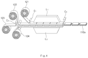
- FIG. 4 is a process diagram illustrating a manufacturing process of the radical unit in FIG. 2 ;
- FIG. 5 is a side view illustrating a third structure of a radical unit according to the present disclosure.
- FIG. 6 is an exploded perspective view illustrating the radical unit in FIG. 5 ;
- FIG. 7 is a process diagram illustrating a manufacturing process of the radical unit in FIG. 5 ;
- FIG. 8 is a side view illustrating a fourth structure of a radical unit according to the present disclosure.
- FIG. 9 is an exploded perspective view illustrating the radical unit in FIG. 8 ;
- FIG. 10 is a process diagram illustrating a manufacturing process of the radical unit in FIG. 8 ;
- FIG. 11 is a perspective view illustrating the First Embodiment of an electrode fixing part according to the present disclosure.
- FIG. 12 is a perspective view illustrating the Second Embodiment of an electrode fixing part according to the present disclosure.
- FIG. 13 is a perspective view illustrating the Third Embodiment of an electrode fixing part according to the present disclosure.
- FIG. 14 is a perspective view illustrating the Fourth Embodiment of an electrode fixing part according to the present disclosure.
- FIG. 15 is a perspective view illustrating the Fifth Embodiment of an electrode fixing part according to the present disclosure.
- FIG. 16 is a perspective view illustrating the Sixth Embodiment of an electrode fixing part according to the present disclosure.
- the electrode assembly according to the present disclosure basically includes an electrode stack part and an electrode fixing part.
- the electrode stack part (see reference numeral 100 a , etc. in FIG. 1 ) includes at least one radical unit (see 110 a , etc. in FIG. 2 ). That is, the electrode stack part 100 may be formed by including one radical unit 110 or at least two radical units 110 .
- the electrode stack part 100 may be formed by stacking the radical units 110 .
- the electrode stack part 100 a may be formed by stacking one radical unit 110 a and another radical unit, as illustrated in FIG. 1 .
- the electrode stack part 100 may be formed by stacking the radical units 110 . That is, the radical units 110 may be formed in advance, and then stacked one by one to form the electrode stack part 100 .
- the electrode stack part 100 according to the present disclosure is characterized in that the electrode stack part 100 is formed by repeatedly stacking the radical units 110 .
- the radical units 110 may be precisely aligned, and the productivity may be improved. (For example, a folding process applied in the stack/folding type electrode may be omitted).
- the radical unit 100 is formed by stacking a first electrode 111 , a separator 112 , a second electrode 113 and the separator 112 .
- the radical unit 110 has a basically four-layered structure. More particularly, the radical unit 110 may be obtained by stacking the first electrode 111 , the separator 112 , the second electrode 113 and the separator 112 one by one from the upper portion to the lower portion, as illustrated in FIG. 2 , or by stacking the first electrode 111 , the separator 112 , the second electrode 113 and the separator 112 one by one from the lower portion to the upper portion, as illustrated in FIG. 3 .
- the first electrode 111 and the second electrode 112 may be opposite electrodes from each other.
- the first electrode 111 is an anode
- the second electrode 113 may be a cathode.
- the electrodes may have inverse polarity.
- the first electrode when the radical units are repeatedly stacked to form the electrode stack part, the first electrode may be positioned at the uppermost portion or the lowermost portion of the electrode stack part.
- the separator may be additionally stacked on the first electrode positioned at the outermost portion to insulate the first electrode positioned at the outermost portion and exposed to exterior (for example, the first electrode positioned at the uppermost portion in FIG. 1 ) from the case.
- a separator sheet may also be applied instead of the separator.
- the electrode stack part may be wrapped with the separator sheet to insulate the first electrode positioned at the outermost portion from the case.
- the first electrode positioned at the outermost portion may be insulated from the case by means of an electrode fixing part, which will be described herein below.
- the radical unit 110 a may be formed by the following process (see FIG. 4 ). First, a first electrode material 121 , a first separator material 122 , a second electrode material 123 and a second separator material 124 are prepared. In this case, the electrode materials 121 and 123 may be cut into a certain size to form the electrodes 111 and 113 . The same process is conducted for the first and second separator materials 122 and 124 . To automate the manufacturing process, the electrode material and the separator material may have a wrapped shape on a roll. After preparing the materials, the first electrode material 121 is cut into a certain size through a cutter C 1 . Then, the second electrode material 123 is also cut into a certain size through a cutter C 2 .
- the first electrode material 121 having the certain size is supplied on the first separator material 122 .
- the second electrode material 123 having the certain size is also supplied on the second separator material 124 . Then, all of the materials are supplied to laminators L 1 and L 2 .
- the electrode stack part 100 may be formed by repeatedly stacking the radical units 110 as described above. However, when the electrode and the separator constituting the radical unit 110 are separated from each other, the repetitive stacking of the radical units 110 may be difficult. Thus, the electrode and the separator may be attached to each other when forming the radical unit 110 .
- the laminators L 1 and L 2 are used to attach the electrode and the separator to each other. That is, the electrode material and the separator material are attached to each other by applying a pressure or a heat and pressure onto the materials by the laminators L 1 and L 2 . Through the attachment, the radical unit 110 may maintain the shape thereof more stably.
- the radical unit 110 a may be formed.
- Various kinds of inspections on the radical unit 110 a may be additionally conducted as occasion demands. For example, inspections such as a thickness inspection, a vision inspection, a short inspection, and the like may be additionally conducted.
- the surface of the separator may be coated with a coating material having adhesiveness.
- the coating material may be a mixture of inorganic particles and a binder polymer.
- the inorganic particles may improve the thermal stability of the separator. That is, the inorganic particles may prevent the contraction of the separator at a high temperature.
- the binder polymer may fix the inorganic particles.
- the inorganic particles may have a certain porous structure. Due to the porous structure, ions may easily move from the cathode to the anode even though the separator is coated with the inorganic particles.
- the binder polymer may maintain the inorganic particles on the separator stably to improve the mechanical stability of the separator.
- the binder polymer may attach the separator onto the electrode more stably.
- the separator may be formed by using a polyolefin-based separator base.
- the electrodes 111 and 113 are positioned at both sides of the separator 112 , however, the electrode 113 is positioned only at one side of the other separator 112 .
- the coating material may be coated on both sides of the separator 112 , while the coating material may be coated only on one side of the other separator 112 . That is, the coating material may be coated on both sides of the separator 112 facing the first electrode 111 and the second electrode 113 , and the coating material may be coated on one side of the other separator 112 facing the second electrode 113 .
- the attachment within the radical unit by means of the coating material may be sufficient.
- the coating may be conducted only on one side of the separator 112 as described above. Since the radical units may be attached to each other by means of a heat press method, etc., the coating may be conducted on both sides of the separator 112 as occasion demands. That is, the separator 112 may be coated on one side facing the second electrode 113 and on the opposite side thereof as occasion demands.
- a direct pressurization onto the separator by using a certain object is not preferred.
- the separator is extended lengthily and outward from the electrode.
- the terminal of the separator 112 and the terminal of another separator 112 may be combined to each other.
- the terminal of the separator 112 and the terminal of another separator 112 may be welded to each other by means of an ultrasonic welding.
- a direct pressurization on an object using a horn is necessary for conducting the ultrasonic welding.
- the horn may attach to the separator due to the coating material having the adhesiveness when the terminal portion of the separator is directly pressurized by means of the horn. In this case, the apparatus may be out of order. Therefore, the direct pressurization onto the separator by using a certain object is not preferable when the coating material having the adhesiveness is coated on the separator.
- the radical unit 110 does not necessarily have a four-layered structure.
- the radical unit 110 may have an eight-layered structure obtained by stacking the first electrode 111 , the separator 112 , the second electrode 113 , the separator 112 , the first electrode 111 , the separator 112 , the second electrode 113 and the separator 112 one by one. That is, the radical unit 110 may be formed as the eight-layered structure by repeating the four-layered structures.
- the radical unit 110 c may form an eight-layered structure including a bicell 116 and a supplementary cell 117 .
- the bicell 116 is formed by stacking the first electrode 111 , the separator 112 , the second electrode 113 , the separator 112 and the first electrode 111 one by one from the upper portion to the lower portion (or from the lower portion to the upper portion).
- the first electrode is a cathode
- the thus obtained structure may be called an A-type bicell
- the thus obtained structure may be called a C-type bicell.
- the supplementary cell 117 may be formed by stacking the separator 112 , the second electrode 113 and the separator 112 one by one from the first electrode 111 of the bicell 116 , that is, subsequently from the first electrode 111 of the bicell 116 to outward.
- the first electrode 111 of the bicell 116 may be the first electrode 111 positioned at the uppermost portion of the bicell 116 , or the first electrode 111 positioned at the lowermost portion of the bicell 116 .
- FIG. 5 illustrates an example embodiment in which the supplementary cell is stacked on the first electrode positioned at the lowermost portion of the bicell.
- the electrode stack part 100 may be formed by repeatedly stacking the radical units 110 c having the above-described eight-layered structure. (Of course, the electrode stack part may be formed by using only one radical unit.) Through forming the radical unit 110 c as described above, the electrode stack part 100 may be formed only by means of the stack process other than the folding process while using one of the A-type bicell or the C-type bicell applied in the stack/folding structure.
- the radical unit 110 c having the eight-layered structure as described above may be formed by the following process (see FIG. 7 ). First, a first electrode material, a separator material, a second electrode material, a separator material and a first electrode material are prepared. Then, these materials are stacked one by one and supplied to first laminators L 1 and L 2 . In the first laminators L 1 and L 2 , the materials are laminated into a corresponding structure of the bicell 116 . (The laminating process is the same as the common laminating process.) After that, the separator material, the second electrode material and the separator material are additionally supplied to second laminators L 3 and L 4 . In the second laminators L 3 and L 4 , the materials are laminated into a corresponding structure of the radical unit 110 c.
- the common processes may be applied.
- the electrode assembly may be fabricated by introducing a new process without a folding process, and the cost consumed for equipment investment may be remarkably decreased.
- the radical unit 110 c may be formed by conducting one continuous laminating process, the process may be simplified.
- the second laminating process may be conducted at a lower temperature and under a lower pressure when compared with the first laminating process, the cost may be decreased.
- the second laminating process may be conducted by laminating the supplementary cell 117 on one side of the bicell 116 .
- the upper part L 3 and the lower part L 4 of the second laminator may be operated at different temperatures. Therefore, the power consumption of the second laminator may be decreased.
- the radical unit 110 d may have an eight-layered structure as illustrated in FIGS. 8 and 9 . That is, as illustrated in FIG. 8 , the radical unit 110 d may be formed as an eight-layered structure including the bicell 116 formed by stacking the first electrode 111 , the separator 112 , the second electrode 113 , the separator 112 and the first electrode 111 one by one, and the supplementary cell 118 formed by stacking the separator 112 stacked on one of the two first electrodes 111 , and the separator 112 and the second electrode 113 stacked on the other one of the two first electrodes 111 one by one.
- FIG. 8 the radical unit 110 d may be formed as an eight-layered structure including the bicell 116 formed by stacking the first electrode 111 , the separator 112 , the second electrode 113 , the separator 112 and the first electrode 111 one by one, and the supplementary cell 118 formed by stacking the separator 112 stacked on one of the two first electrodes 111 , and the
- the stacking may be conducted inversely.
- the above-described radical unit 110 d having the eight-layered structure may be formed by the following process (see FIG. 10 ). First, the first electrode material, the separator material, the second electrode material, the separator material and the first electrode material are prepared. Then, these materials are stacked one by one and supplied to the first laminators L 1 and L 2 . In the first laminators L 1 and L 2 , the materials are laminated into a corresponding structure to the bicell 116 .
- the laminating process is the same as the common laminating process.) Subsequently after that, the materials are supplied to the second laminators L 3 and L 4 so that the separator 112 may be stacked on the first electrode 111 positioned at the uppermost portion, and so that the separator 112 and the second electrode 113 are stacked one by one from the first electrode 111 positioned at the lowermost portion of the bicell 116 to the outward. In the second laminators L 3 and L 4 , the materials are laminated into a corresponding structure to the radical unit 110 d .
- the laminating process of the separator 112 on the first electrode 111 positioned at the uppermost portion, and the laminating process of the separator 112 and the second electrode 113 one by one from the first electrode 111 positioned at the lowermost portion of the bicell 116 to the outward may be conducted in separate laminators.
- the electrode assembly according to the present disclosure is basically characterized in that the electrode stack part 100 is formed only by a stack process other than a folding process. That is, according to the present disclosure, the radical unit 110 is formed by the laminating process, and then, one or more of the radical units 100 are stacked to form the electrode stack part 100 . In order to fix the electrode stack part 100 more stably, the electrode assembly according to the present disclosure includes an electrode fixing part 200 for wrapping and fixing the electrode stack part 100 .
- the electrode fixing part 200 may be accomplished in various embodiments as described herein below.
- the electrode fixing part 200 may include an upper fixing member 211 provided at the upper portion of the electrode stack part 100 , and a lower fixing member 212 provided at the lower portion of the electrode stack part 100 , as illustrated in FIG. 11 .
- the lower fixing member 212 may be connected with the upper fixing member 211 to fit closely the electrode stack part 100 along with the upper fixing member 211 .
- the electrode fixing part 200 a may fix the electrode stack part 100 . That is, the electrode stack part 100 may be fixed by an electrode fixing part 200 a by positioning the electrode stack part 100 between the upper fixing member 211 and the lower fixing member 212 , and attaching the upper fixing member 211 and the lower fixing member 212 to each other.
- the lower fixing member 212 may be attached to the upper fixing member 211 by means of an ultrasonic welding or a heat sealing.
- a closing part 216 may be formed at the attaching part of the upper fixing member 211 and the lower fixing member 212 .
- the closing part 216 may be formed at both sides.
- the closing part 216 may have a width (d) of about 1 to 5 mm.
- welding strength may be about 30 to 100 gf.
- a sealing temperature may be from about 120° C. to 180° C.
- a sealing thickness may be about 50% to 80% of an original material
- a sealing strength may be about 30 to 100 gf.
- an electrode fixing part 200 b may be a fixing sheet 221 having a sheet shape and formed to wrap the electrode stack part 100 , as illustrated in FIG. 12 .
- one terminal and the other terminal of the fixing sheet may be connected to each other by means of the ultrasonic welding or the heat sealing to wrap the electrode stack part 100 . That is, the electrode stack part 100 may be wrapped while making one round, by using the fixing sheet 221 , and the one terminal and the other terminal of the fixing sheet 221 contacting to each other may be connected. Then, the electrode stack part 100 may be fixed by the electrode fixing part 200 b.
- the electrode fixing part 200 may be formed by using a different material from the separator 112 , for example, by using at least one of a non-woven fabric, PP, PE, and PET. More particularly, the electrode fixing part 200 may be formed by using a non-woven fabric having a pore size of about 1 ⁇ m or over. Alternatively, the electrode fixing part 200 may be formed by using at least one of the PP, the PE and the PET having a thickness of about 20 to 100 ⁇ m.
- an electrode fixing part 200 c may have a tube shape including a first opening 231 , a second opening facing the first opening 231 , and an inner space extended from the first opening 231 to the second opening for receiving the electrode stack part 100 , as illustrated in FIG. 13 .
- the electrode fixing part 200 c as described above may closely fit the electrode stack part 100 by the contraction due to heat. That is, by receiving the electrode stack part 100 in the inner space of the electrode fixing part 200 c and by heating the electrode fixing part 200 c , the electrode fixing part 200 c may be contracted and closely fit the electrode stack part 100 . Through the fit, the electrode fixing part 200 c may fix the electrode stack part 100 .
- An electrode fixing part 200 d may be formed as a porous insulating tape, as illustrated in FIG. 14 . That is, the electrode stack part 100 may be fixed by wrapping the electrode stack part 100 using the porous insulating tape.
- an electrode fixing part 200 e may be extended from the upper surface of the electrode stack part 100 along the side surface of the electrode stack part 100 to the lower surface of the electrode stack part 100 to fix the electrode stack part 100 , as illustrated in FIG. 15 .
- an end portion of a polymer tape is fixed to the upper surface of the electrode stack part 100 .
- the other end portion of the polymer tape is drawn along the side surface of the electrode stack part 100 and is fixed to the lower surface of the electrode stack part 100 .
- the electrode stack part 100 may be fixed by means of the polymer tape through a heat welding.
- the electrode fixing part 200 f may wrap the electrode stack part 100 by at least one round. As described above, the electrode fixing part may not completely wrap the electrode stack part.
- a radical unit basically includes a cathode and an anode.
- the radical unit includes a separator between the cathode and the anode.
- the cathode may be manufactured, for example, by coating a mixture of a cathode active material, a conductive material and a mixture of a binder (slurry) on a cathode current collector, drying and pressing. The mixture may further include a filler as occasion demands.
- the cathode may be formed as a sheet shape and installed on a roll.
- a cathode current collector is generally manufactured to a thickness of about 3 to 500 ⁇ m.
- a material not inducing the chemical change and having a high conductivity may be used.
- stainless steel, aluminum, nickel, titanium, calcined carbon, a surface treated material of aluminum or stainless steel with carbon, nickel, titanium, silver, or the like may be typically used.
- minute embossing may be formed on the surface of the cathode current collector.
- the cathode current collector may have various shapes such as a film, a sheet, a foil, a net, a porous body, a foamed body, a non-woven fabric, and the like.
- a conductive material is added into a mixture including the cathode active material by 1 to 50 wt % based on the total amount of the mixture.
- the conductive material may be formed by using a material having conductivity without inducing chemical change.
- graphite such as natural graphite, synthetic graphite, etc.
- carbon black such as carbon black, acetylene black, ketjen black, channel black, furnace black, lamp black, thermal black, etc.
- conductive fiber such as carbon fiber, metal fiber, etc.
- a metal powder such as a carbon fluoride powder, an aluminum powder, a nickel powder, etc.
- conductive whisker such as potassium titanate, etc.
- conductive metal oxide such as titanium oxide, etc.
- a conductive material such as polyphenylene derivatives, etc.
- a binder is a component assisting the bonding of the active material with the conductive material and the bonding with the current collector, and is commonly included by about 1 to 50 wt % based on the total amount of the mixture including the cathode active material.
- Typical examples of the binder may include polyfluoro vinylidene, polyvinyl alcohol, carboxymethyl cellulose (CMC), starch, hydroxypropyl cellulose, regenerated cellulose, polyvinyl pyrrolidone, tetrafluoroethylene, polyethylene, polypropylene, ethylene-propylene-diene polymer (EPDM), sulfonated EPDM, styrene butadiene rubber, fluorine rubber, various copolymers, etc.
- a filler is a component restraining the expansion of the cathode and may be selectively used.
- a material not inducing chemical change and having a fiber phase may be used without limitation.
- an olefin-based polymer such as polyethylene, polypropylene, and the like
- fiber phase material such as glass fiber, carbon fiber, and the like may be used.
- An anode may be manufactured by coating an anode current collector with an anode active material, drying and pressing.
- a conductive material, a binder, a filler, etc. may be selectively included as occasion demands.
- the anode may be formed as a sheet shape and may be installed on a roll.
- An anode current collector is generally manufactured to a thickness of about 3 to 500 ⁇ m.
- a material not inducing chemical change and having conductivity may be used.
- copper, stainless steel, aluminum, nickel, titanium, calcined carbon, a surface treated material of copper or stainless steel with carbon, nickel, titanium, silver, an aluminum-cadmium alloy, etc. may be used.
- minute embossing may be formed on the surface of the anode current collector.
- the anode current collector may have various shapes such as a film, a sheet, a foil, a net, a porous body, a foamed body, a non-woven fabric, etc.
- An anode active material may include, for example, carbon such as non-graphitizable carbon, graphite-based carbon, etc.; a metal complex oxide such as Li x Fe 2 O 3 (0 ⁇ x ⁇ 1), Li x WO 2 (0 ⁇ x ⁇ 1), Sn x Me 1 ⁇ x Me′ y O z (Me: Mn, Fe, Pb, Ge; Me′: Al, B, P, Si, elements found in Group 1, Group 2 and Group 3 in a periodic table, halogen; 0 ⁇ x ⁇ 1; 1 ⁇ y ⁇ 3; 1 ⁇ z ⁇ 8), etc.; a lithium metal; a lithium alloy; a silicon-based alloy; a tin-based alloy; a metal oxide such as SnO, SnO 2 , PbO, PbO 2 , Pb 2 O 3 , Pb 3 O 4 , Sb 2 O 3 , Sb 2 O 4 , Sb 2 O 5 , GeO, GeO 2 , Bi 2 O 3 , Bi 2 O 4
- a separator may be melt by the pressure, or the heat and pressure of a laminator to be attached onto the cathode or the anode.
- the electrode and the separator may make a stable interface contact. (Further, the contact may be accomplished separately through the above-described SRS coating.)
- the separator may have insulating properties.
- the separator may have a porous structure for the movement of ions.
- the separator may have the pore diameter of from about 0.01 to 10 ⁇ m.
- the thickness of the separator may be generally about 5 to 300 ⁇ m.
- the separator may be formed into a thin film having high ion transmittance, high mechanical strength and high insulating properties.
- the separator (the separator sheet) may be an olefin-based polymer such as chemical-resistant and hydrophobic polypropylene, etc; a sheet or a non-woven fabric formed by using glass fiber or polyethylene, etc.
- the solid electrolyte may also function as the separator.
- a polyethylene film, a polypropylene film, or a multi-layered film obtained by combining the films, or a polymer film for a polymer electrolyte or a gel-type polymer electrolyte such as polyvinylidene fluoride, polyethylene oxide, polyacrylonitrile, or polyvinylidene fluoride hexafluoropropylene copolymer may be used.
- the electrode assembly according to the present disclosure may be applied in an electrochemical cell producing electricity through the electrochemical reaction of a cathode and an anode.
- Typical examples of the electrochemical cell include a super capacitor, an ultra capacitor, a secondary battery, a fuel battery, an apparatus for electrolysis, an electrochemical reactor, and the like.
- the electrode assembly according to the present disclosure may be particularly and preferably applied in the secondary battery (for example, lithium secondary battery).
- a lithium secondary battery is used as a power source of a medium and large size device as well as a small size device.
- a battery module may be preferably formed by using the secondary battery according to the present disclosure as one unit battery.
- a battery pack including the battery module may be used as a power source in a power tool; an electric vehicle selected from the group consisting of an electric vehicle (EV), a hybrid electric vehicle (HEV), and a plug-in hybrid electric vehicle (PHEV); an E-bike; an E-scooter; an electric golf cart; an electric truck; an electric commercial vehicle, and the like.
- the present disclosure relates to an electrode assembly fabricated by a stacking method other than a folding method and accomplishing minute alignment and stable fixing, and an electrochemical cell including the same, so that the present disclosure has industrial applicability.
Abstract
Description
Claims (13)
Priority Applications (1)
| Application Number | Priority Date | Filing Date | Title |
|---|---|---|---|
| US15/861,233 US10763534B2 (en) | 2012-06-28 | 2018-01-03 | Electrode assembly and electrochemical cell including the same |
Applications Claiming Priority (7)
| Application Number | Priority Date | Filing Date | Title |
|---|---|---|---|
| KR20120069832 | 2012-06-28 | ||
| KR10-2012-0069832 | 2012-06-28 | ||
| KR1020130075040A KR101561339B1 (en) | 2012-06-28 | 2013-06-28 | Electrode assembly and electrochemical cell containing the same |
| KR10-2013-0075040 | 2013-06-28 | ||
| PCT/KR2013/005760 WO2014003481A1 (en) | 2012-06-28 | 2013-06-28 | Electrode assembly and electrochemical device containing same |
| US14/290,728 US9899698B2 (en) | 2012-06-28 | 2014-05-29 | Electrode assembly and electrochemical cell including the same |
| US15/861,233 US10763534B2 (en) | 2012-06-28 | 2018-01-03 | Electrode assembly and electrochemical cell including the same |
Related Parent Applications (1)
| Application Number | Title | Priority Date | Filing Date |
|---|---|---|---|
| US14/290,728 Continuation US9899698B2 (en) | 2012-06-28 | 2014-05-29 | Electrode assembly and electrochemical cell including the same |
Publications (2)
| Publication Number | Publication Date |
|---|---|
| US20180131031A1 US20180131031A1 (en) | 2018-05-10 |
| US10763534B2 true US10763534B2 (en) | 2020-09-01 |
Family
ID=50140256
Family Applications (2)
| Application Number | Title | Priority Date | Filing Date |
|---|---|---|---|
| US14/290,728 Active 2033-11-22 US9899698B2 (en) | 2012-06-28 | 2014-05-29 | Electrode assembly and electrochemical cell including the same |
| US15/861,233 Active 2033-10-12 US10763534B2 (en) | 2012-06-28 | 2018-01-03 | Electrode assembly and electrochemical cell including the same |
Family Applications Before (1)
| Application Number | Title | Priority Date | Filing Date |
|---|---|---|---|
| US14/290,728 Active 2033-11-22 US9899698B2 (en) | 2012-06-28 | 2014-05-29 | Electrode assembly and electrochemical cell including the same |
Country Status (8)
| Country | Link |
|---|---|
| US (2) | US9899698B2 (en) |
| EP (1) | EP2750234B1 (en) |
| JP (1) | JP6093370B2 (en) |
| KR (2) | KR101561339B1 (en) |
| CN (1) | CN104054205B (en) |
| PL (1) | PL2750234T3 (en) |
| TW (1) | TWI484686B (en) |
| WO (1) | WO2014003481A1 (en) |
Families Citing this family (35)
| Publication number | Priority date | Publication date | Assignee | Title |
|---|---|---|---|---|
| JP6344027B2 (en) * | 2014-04-14 | 2018-06-20 | 株式会社豊田自動織機 | Power storage device and method for manufacturing power storage device |
| KR101654677B1 (en) * | 2014-07-29 | 2016-09-06 | 주식회사 엘지화학 | Stack and folding-type electrode assembly and method for fabricating the same |
| KR102221807B1 (en) * | 2014-08-11 | 2021-03-02 | 삼성에스디아이 주식회사 | Secondary battery |
| KR102360413B1 (en) * | 2015-02-16 | 2022-02-09 | 삼성에스디아이 주식회사 | Secondary Battery |
| KR101850583B1 (en) * | 2015-02-27 | 2018-05-31 | 주식회사 엘지화학 | Stack-folding typed electrode assembly |
| DE102015218533A1 (en) * | 2015-09-28 | 2017-03-30 | Robert Bosch Gmbh | Process for producing an electrode composite |
| JP6594738B2 (en) * | 2015-11-02 | 2019-10-23 | 株式会社エンビジョンAescエナジーデバイス | Film outer battery |
| KR102080253B1 (en) * | 2015-11-06 | 2020-02-24 | 주식회사 엘지화학 | Electrode assembly |
| KR101927456B1 (en) | 2015-11-11 | 2018-12-10 | 주식회사 엘지화학 | Secondary battery and manufacturing method thereof |
| WO2017082594A1 (en) * | 2015-11-11 | 2017-05-18 | 주식회사 엘지화학 | Secondary battery and manufacturing method thereof |
| CN105870511B (en) * | 2016-06-13 | 2019-06-21 | 合肥国轩高科动力能源有限公司 | A kind of manufacturing method of lithium ion laminated battery battery core |
| JP6946295B2 (en) * | 2016-07-28 | 2021-10-06 | 三洋電機株式会社 | How to manufacture a secondary battery |
| KR102225091B1 (en) * | 2017-01-18 | 2021-03-09 | 주식회사 엘지화학 | Electrode Assembly with Separator Structure for High Capacity and Secondary Battery Cell Having the Same |
| JP2018170130A (en) * | 2017-03-29 | 2018-11-01 | リチウム エナジー アンド パワー ゲゼルシャフト ミット ベシュレンクテル ハフッング ウント コンパニー コマンディトゲゼルシャフトLithium Energy and Power GmbH & Co. KG | Power storage element |
| KR102217444B1 (en) * | 2017-04-06 | 2021-02-22 | 주식회사 엘지화학 | Electrode assembly and manufactureing method for the same |
| KR102063583B1 (en) * | 2017-05-08 | 2020-01-09 | 주식회사 엘지화학 | Secondary battery, apparatus and method for manufacturing the same |
| JP6563469B2 (en) * | 2017-12-15 | 2019-08-21 | 本田技研工業株式会社 | Electrode bonding method and electrode bonding apparatus |
| CN110120557B (en) * | 2018-02-05 | 2021-01-15 | 宁德新能源科技有限公司 | Protection device and battery |
| JP7070052B2 (en) * | 2018-04-27 | 2022-05-18 | トヨタ自動車株式会社 | All solid state battery |
| WO2020045819A1 (en) | 2018-08-27 | 2020-03-05 | 삼성디스플레이 주식회사 | Display panel and display device comprising same |
| DE102018215070A1 (en) | 2018-09-05 | 2020-03-05 | Gs Yuasa International Ltd. | Method of forming an electrode stack |
| WO2020112618A1 (en) * | 2018-11-28 | 2020-06-04 | Cadenza Innovation, Inc. | Modular battery system |
| DE102018221571A1 (en) * | 2018-12-12 | 2020-06-18 | Volkswagen Aktiengesellschaft | Method and device for producing an electrode stack |
| KR102328527B1 (en) * | 2018-12-24 | 2021-11-18 | 주식회사 엘지에너지솔루션 | Stack-type electrode assembly with no deflection of the electrode and manufacturing methods thereof |
| KR102316340B1 (en) * | 2019-01-22 | 2021-10-22 | 주식회사 엘지에너지솔루션 | Electrode Assembly, Secondary battery with the Same and Method of thereof and Battery Pack |
| US11189828B2 (en) * | 2019-02-27 | 2021-11-30 | Battelle Memorial Institute | Lithium metal pouch cells and methods of making the same |
| KR20200107018A (en) | 2019-03-05 | 2020-09-16 | 삼성디스플레이 주식회사 | Dispcay device |
| KR102544744B1 (en) * | 2019-03-12 | 2023-06-16 | 주식회사 엘지에너지솔루션 | Lamination apparatus and method for secondary battery |
| KR20200113094A (en) | 2019-03-21 | 2020-10-06 | 삼성디스플레이 주식회사 | Display device and method for manufacturing the same |
| US11273662B2 (en) | 2019-04-04 | 2022-03-15 | Assa Abloy Ab | Secure multilayer structure with security element located on a window |
| KR20200130550A (en) | 2019-05-08 | 2020-11-19 | 삼성디스플레이 주식회사 | Display device and method of manufacturing for the display device |
| KR20200131181A (en) * | 2019-05-13 | 2020-11-23 | 주식회사 엘지화학 | Electrode assembly manufacturing method, electrode assembly manufactured from thereof and rechargeable battery |
| JP7266214B2 (en) * | 2019-09-30 | 2023-04-28 | パナソニックIpマネジメント株式会社 | Power tools and battery packs |
| KR20210052798A (en) | 2019-10-31 | 2021-05-11 | 삼성디스플레이 주식회사 | Touch sensor and display device including the same |
| CN112652802B (en) * | 2020-12-30 | 2022-12-13 | 蜂巢能源科技有限公司 | Lamination device |
Citations (27)
| Publication number | Priority date | Publication date | Assignee | Title |
|---|---|---|---|---|
| US6040085A (en) * | 1994-03-31 | 2000-03-21 | Valence Technology, Inc. | Battery packaging |
| KR20010082059A (en) | 2000-02-08 | 2001-08-29 | 성재갑 | Stacked electrochemical cell and method for preparing the same |
| KR20010082060A (en) | 2000-02-08 | 2001-08-29 | 성재갑 | Multiply stacked electrochemical cell and method for preparing the same |
| US6387565B1 (en) * | 1998-01-19 | 2002-05-14 | Mitsubishi Denki Kabushiki Kaisha | Battery having an adhesive resin layer containing a filler |
| JP2002151159A (en) | 2000-09-01 | 2002-05-24 | Nisshinbo Ind Inc | Lithium battery |
| US20060159999A1 (en) | 2001-07-23 | 2006-07-20 | Kejha Joseph B | Method of automated prismatic electrochemical cells production and method of the cell assembly and construction |
| KR20060092429A (en) | 2005-02-17 | 2006-08-23 | 주식회사 엘지화학 | Stability-improved secondary battery containing fixing member |
| US20070218355A1 (en) | 2006-03-14 | 2007-09-20 | Lg Chem, Ltd. | Multi-layered type electrochemistry cell of improved safety |
| KR20070101445A (en) | 2006-04-10 | 2007-10-17 | 삼성에스디아이 주식회사 | Secondary battery |
| JP2008192432A (en) | 2007-02-02 | 2008-08-21 | Sony Corp | Secondary battery and secondary battery device |
| US20090029253A1 (en) | 2005-04-28 | 2009-01-29 | Nissan Motor Co., Ltd. | Positive electrode material for lithium ion battery with nonaqueous electrolyte, and battery using the same |
| US20100028769A1 (en) | 2008-07-30 | 2010-02-04 | Nec Tokin Corporation | Stacked secondary battery |
| JP2010514112A (en) | 2006-12-20 | 2010-04-30 | ヴァルタ マイクロバッテリー ゲゼルシャフト ミット ベシュレンクテル ハフツング | Electrochemical device comprising adhesive bonded composite of electrode and separator |
| JP2011054503A (en) | 2009-09-04 | 2011-03-17 | Hitachi Maxell Ltd | Separator for electrochemical element, electrochemical element and manufacturing method thereof |
| WO2011040704A2 (en) | 2009-09-29 | 2011-04-07 | 주식회사 엘지화학 | Method for producing a separator, separator produced by same, and method for producing an electrochemical device comprising the separator |
| KR20110037781A (en) | 2009-10-07 | 2011-04-13 | 에스케이이노베이션 주식회사 | Electrode assembly for battery and manufacturing thereof |
| JP2011086506A (en) | 2009-10-15 | 2011-04-28 | Komatsu Ntc Ltd | Laminated battery manufacturing device |
| US20110135996A1 (en) | 2009-12-07 | 2011-06-09 | Changbum Ahn | Electrode assembly block and method of manufacturing the same, and secondary battery and method of manufacturing the same |
| US20110159351A1 (en) * | 2009-12-31 | 2011-06-30 | Lightening Energy | Modular battery with polymeric compression sealing |
| US20110195300A1 (en) | 2008-10-20 | 2011-08-11 | Nec Energy Devices, Ltd. | Stacked lithium ion secondary battery |
| US20110223465A1 (en) | 2009-03-31 | 2011-09-15 | Mitsubishi Heavy Industries, Ltd. | Rechargeable battery and battery system |
| KR20110112241A (en) | 2010-04-06 | 2011-10-12 | 주식회사 엘지화학 | Improved stack-type cell and bi-cell, electrode assembly for secondary battery utilizing the same and manufacturing method thereof |
| WO2011145608A1 (en) | 2010-05-19 | 2011-11-24 | 日産自動車株式会社 | Bipolar secondary battery |
| US20120077075A1 (en) | 2010-09-24 | 2012-03-29 | Sanyo Electric Co., Ltd. | Stack type battery |
| WO2012074218A2 (en) | 2010-12-02 | 2012-06-07 | 주식회사 엘지화학 | Device for manufacturing battery cell |
| US20120308878A1 (en) | 2011-05-30 | 2012-12-06 | Sakashita Kazuya | Secondary battery and manufacturing method thereof |
| US20140212729A1 (en) | 2012-05-23 | 2014-07-31 | Lg Chem. Ltd. | Electrode assembly and electrochemical cell containing the same |
Family Cites Families (1)
| Publication number | Priority date | Publication date | Assignee | Title |
|---|---|---|---|---|
| EP2346400A1 (en) | 2008-10-31 | 2011-07-27 | Nexstim Oy | Method, apparatus and computer program for non-invasive brain stimulation when target muscles are suitably active |
-
2013
- 2013-06-28 JP JP2014544689A patent/JP6093370B2/en active Active
- 2013-06-28 CN CN201380004570.1A patent/CN104054205B/en active Active
- 2013-06-28 PL PL13808457T patent/PL2750234T3/en unknown
- 2013-06-28 KR KR1020130075040A patent/KR101561339B1/en active IP Right Grant
- 2013-06-28 WO PCT/KR2013/005760 patent/WO2014003481A1/en active Application Filing
- 2013-06-28 TW TW102123208A patent/TWI484686B/en active
- 2013-06-28 EP EP13808457.9A patent/EP2750234B1/en active Active
-
2014
- 2014-05-29 US US14/290,728 patent/US9899698B2/en active Active
-
2015
- 2015-06-03 KR KR1020150078677A patent/KR101761002B1/en active IP Right Grant
-
2018
- 2018-01-03 US US15/861,233 patent/US10763534B2/en active Active
Patent Citations (38)
| Publication number | Priority date | Publication date | Assignee | Title |
|---|---|---|---|---|
| US6040085A (en) * | 1994-03-31 | 2000-03-21 | Valence Technology, Inc. | Battery packaging |
| US6387565B1 (en) * | 1998-01-19 | 2002-05-14 | Mitsubishi Denki Kabushiki Kaisha | Battery having an adhesive resin layer containing a filler |
| KR20010082059A (en) | 2000-02-08 | 2001-08-29 | 성재갑 | Stacked electrochemical cell and method for preparing the same |
| KR20010082060A (en) | 2000-02-08 | 2001-08-29 | 성재갑 | Multiply stacked electrochemical cell and method for preparing the same |
| US20020160257A1 (en) | 2000-02-08 | 2002-10-31 | Hyang-Mok Lee | Stacked electrochemical cell and method for preparing the same |
| US20020160258A1 (en) | 2000-02-08 | 2002-10-31 | Hyang-Mok Lee | Multiply stacked electrochemical cell and method for preparing the same |
| JP2002151159A (en) | 2000-09-01 | 2002-05-24 | Nisshinbo Ind Inc | Lithium battery |
| US20060159999A1 (en) | 2001-07-23 | 2006-07-20 | Kejha Joseph B | Method of automated prismatic electrochemical cells production and method of the cell assembly and construction |
| KR20060092429A (en) | 2005-02-17 | 2006-08-23 | 주식회사 엘지화학 | Stability-improved secondary battery containing fixing member |
| US20090029253A1 (en) | 2005-04-28 | 2009-01-29 | Nissan Motor Co., Ltd. | Positive electrode material for lithium ion battery with nonaqueous electrolyte, and battery using the same |
| US20070218355A1 (en) | 2006-03-14 | 2007-09-20 | Lg Chem, Ltd. | Multi-layered type electrochemistry cell of improved safety |
| KR20070101445A (en) | 2006-04-10 | 2007-10-17 | 삼성에스디아이 주식회사 | Secondary battery |
| US20110269012A1 (en) | 2006-12-20 | 2011-11-03 | Varta Microbattery Gmbh, A Corporation Of Germany | Galvanic element with composite of electrodes, and separator formed by an adhesive |
| JP2010514112A (en) | 2006-12-20 | 2010-04-30 | ヴァルタ マイクロバッテリー ゲゼルシャフト ミット ベシュレンクテル ハフツング | Electrochemical device comprising adhesive bonded composite of electrode and separator |
| JP2008192432A (en) | 2007-02-02 | 2008-08-21 | Sony Corp | Secondary battery and secondary battery device |
| JP2010033922A (en) | 2008-07-30 | 2010-02-12 | Nec Tokin Corp | Layered secondary battery |
| US20100028769A1 (en) | 2008-07-30 | 2010-02-04 | Nec Tokin Corporation | Stacked secondary battery |
| US20110195300A1 (en) | 2008-10-20 | 2011-08-11 | Nec Energy Devices, Ltd. | Stacked lithium ion secondary battery |
| US20110223465A1 (en) | 2009-03-31 | 2011-09-15 | Mitsubishi Heavy Industries, Ltd. | Rechargeable battery and battery system |
| JP2011054503A (en) | 2009-09-04 | 2011-03-17 | Hitachi Maxell Ltd | Separator for electrochemical element, electrochemical element and manufacturing method thereof |
| US20110259505A1 (en) | 2009-09-29 | 2011-10-27 | Lg Chem, Ltd. | Method for manufacturing separator, separator manufactured therefrom and method for manufacturing electrochemical device having the same |
| WO2011040704A2 (en) | 2009-09-29 | 2011-04-07 | 주식회사 엘지화학 | Method for producing a separator, separator produced by same, and method for producing an electrochemical device comprising the separator |
| KR20110037781A (en) | 2009-10-07 | 2011-04-13 | 에스케이이노베이션 주식회사 | Electrode assembly for battery and manufacturing thereof |
| US20120196167A1 (en) | 2009-10-07 | 2012-08-02 | Sk Innovation Co., Ltd. | Electrode assembly for a battery and method for manufacturing same |
| JP2011086506A (en) | 2009-10-15 | 2011-04-28 | Komatsu Ntc Ltd | Laminated battery manufacturing device |
| US20110135996A1 (en) | 2009-12-07 | 2011-06-09 | Changbum Ahn | Electrode assembly block and method of manufacturing the same, and secondary battery and method of manufacturing the same |
| US20110159351A1 (en) * | 2009-12-31 | 2011-06-30 | Lightening Energy | Modular battery with polymeric compression sealing |
| KR20110112241A (en) | 2010-04-06 | 2011-10-12 | 주식회사 엘지화학 | Improved stack-type cell and bi-cell, electrode assembly for secondary battery utilizing the same and manufacturing method thereof |
| WO2011126310A2 (en) | 2010-04-06 | 2011-10-13 | 주식회사 엘지화학 | Stack-type cell, enhanced bi-cell, electrode assembly for secondary battery using same, and manufacturing method therefor |
| US20120225345A1 (en) | 2010-04-06 | 2012-09-06 | Soo-Young Kim | Stack-type cell or bi-cell, electrode assembly for secondary battery using the same, and manufacturing method thereof |
| WO2011145608A1 (en) | 2010-05-19 | 2011-11-24 | 日産自動車株式会社 | Bipolar secondary battery |
| US20130059179A1 (en) | 2010-05-19 | 2013-03-07 | Nissan Motor Co., Ltd. | Bipolar secondary battery |
| US20120077075A1 (en) | 2010-09-24 | 2012-03-29 | Sanyo Electric Co., Ltd. | Stack type battery |
| WO2012074218A2 (en) | 2010-12-02 | 2012-06-07 | 주식회사 엘지화학 | Device for manufacturing battery cell |
| US20130252069A1 (en) | 2010-12-02 | 2013-09-26 | Lg Chem, Ltd. | Manufacture device of battery cell |
| US20120308878A1 (en) | 2011-05-30 | 2012-12-06 | Sakashita Kazuya | Secondary battery and manufacturing method thereof |
| US20140212729A1 (en) | 2012-05-23 | 2014-07-31 | Lg Chem. Ltd. | Electrode assembly and electrochemical cell containing the same |
| JP2015506059A (en) | 2012-05-23 | 2015-02-26 | エルジー ケム. エルティーディ. | Electrode assembly and electrochemical device including the same |
Non-Patent Citations (2)
| Title |
|---|
| Extended European Search Report for Appl. No. 13808457.9 dated Oct. 8, 2015. |
| International Search Report issued in PCT/KR2013/005760, dated Oct. 16, 2013. |
Also Published As
| Publication number | Publication date |
|---|---|
| JP2014534604A (en) | 2014-12-18 |
| CN104054205B (en) | 2017-03-01 |
| WO2014003481A1 (en) | 2014-01-03 |
| EP2750234A4 (en) | 2015-11-11 |
| EP2750234A1 (en) | 2014-07-02 |
| PL2750234T3 (en) | 2019-10-31 |
| KR20150068941A (en) | 2015-06-22 |
| TW201424093A (en) | 2014-06-16 |
| KR101761002B1 (en) | 2017-07-25 |
| KR101561339B1 (en) | 2015-10-19 |
| US20140272507A1 (en) | 2014-09-18 |
| CN104054205A (en) | 2014-09-17 |
| US20180131031A1 (en) | 2018-05-10 |
| TWI484686B (en) | 2015-05-11 |
| KR20140004015A (en) | 2014-01-10 |
| EP2750234B1 (en) | 2019-04-24 |
| US9899698B2 (en) | 2018-02-20 |
| JP6093370B2 (en) | 2017-03-08 |
Similar Documents
| Publication | Publication Date | Title |
|---|---|---|
| US10763534B2 (en) | Electrode assembly and electrochemical cell including the same | |
| US11081682B2 (en) | Fabricating method of electrode assembly and electrochemical cell containing the same | |
| US10516185B2 (en) | Electrode assembly and electrochemical cell containing the same | |
| US9246186B2 (en) | Electrode assembly, fabricating method of the electrode assembly and electrochemical cell containing the electrode assembly | |
| US9806316B2 (en) | Electrode assembly, fabricating method of the electrode assembly and electrochemical cell containing the electrode assembly | |
| KR101487092B1 (en) | Pouch for secondary battery and secondary battery using the same | |
| EP2899769B1 (en) | Pouch for secondary battery and secondary battery comprising same |
Legal Events
| Date | Code | Title | Description |
|---|---|---|---|
| FEPP | Fee payment procedure |
Free format text: ENTITY STATUS SET TO UNDISCOUNTED (ORIGINAL EVENT CODE: BIG.); ENTITY STATUS OF PATENT OWNER: LARGE ENTITY |
|
| STPP | Information on status: patent application and granting procedure in general |
Free format text: DOCKETED NEW CASE - READY FOR EXAMINATION |
|
| STPP | Information on status: patent application and granting procedure in general |
Free format text: NON FINAL ACTION MAILED |
|
| STPP | Information on status: patent application and granting procedure in general |
Free format text: RESPONSE TO NON-FINAL OFFICE ACTION ENTERED AND FORWARDED TO EXAMINER |
|
| STPP | Information on status: patent application and granting procedure in general |
Free format text: FINAL REJECTION MAILED |
|
| STPP | Information on status: patent application and granting procedure in general |
Free format text: DOCKETED NEW CASE - READY FOR EXAMINATION |
|
| AS | Assignment |
Owner name: LG CHEM, LTD., KOREA, REPUBLIC OF Free format text: ASSIGNMENT OF ASSIGNORS INTEREST;ASSIGNORS:KU, DAE GEUN;KIM, HYUK SU;HUH, JUN WOO;AND OTHERS;REEL/FRAME:052799/0190 Effective date: 20140610 |
|
| STPP | Information on status: patent application and granting procedure in general |
Free format text: PUBLICATIONS -- ISSUE FEE PAYMENT RECEIVED |
|
| STCF | Information on status: patent grant |
Free format text: PATENTED CASE |
|
| AS | Assignment |
Owner name: LG ENERGY SOLUTION, LTD., KOREA, REPUBLIC OF Free format text: ASSIGNMENT OF ASSIGNORS INTEREST;ASSIGNOR:LG CHEM, LTD.;REEL/FRAME:058295/0068 Effective date: 20211027 |
|
| MAFP | Maintenance fee payment |
Free format text: PAYMENT OF MAINTENANCE FEE, 4TH YEAR, LARGE ENTITY (ORIGINAL EVENT CODE: M1551); ENTITY STATUS OF PATENT OWNER: LARGE ENTITY Year of fee payment: 4 |