EP3889464B1 - Zweistufiges getriebe für ein elektrisch angetriebenes fahrzeug - Google Patents
Zweistufiges getriebe für ein elektrisch angetriebenes fahrzeug Download PDFInfo
- Publication number
- EP3889464B1 EP3889464B1 EP20840259.4A EP20840259A EP3889464B1 EP 3889464 B1 EP3889464 B1 EP 3889464B1 EP 20840259 A EP20840259 A EP 20840259A EP 3889464 B1 EP3889464 B1 EP 3889464B1
- Authority
- EP
- European Patent Office
- Prior art keywords
- rotational element
- clutch
- speed mode
- rotational
- speed
- Prior art date
- Legal status (The legal status is an assumption and is not a legal conclusion. Google has not performed a legal analysis and makes no representation as to the accuracy of the status listed.)
- Active
Links
Images





Classifications
-
- F—MECHANICAL ENGINEERING; LIGHTING; HEATING; WEAPONS; BLASTING
- F16—ENGINEERING ELEMENTS AND UNITS; GENERAL MEASURES FOR PRODUCING AND MAINTAINING EFFECTIVE FUNCTIONING OF MACHINES OR INSTALLATIONS; THERMAL INSULATION IN GENERAL
- F16H—GEARING
- F16H3/00—Toothed gearings for conveying rotary motion with variable gear ratio or for reversing rotary motion
- F16H3/44—Toothed gearings for conveying rotary motion with variable gear ratio or for reversing rotary motion using gears having orbital motion
- F16H3/46—Gearings having only two central gears, connected by orbital gears
- F16H3/48—Gearings having only two central gears, connected by orbital gears with single orbital gears or pairs of rigidly-connected orbital gears
- F16H3/52—Gearings having only two central gears, connected by orbital gears with single orbital gears or pairs of rigidly-connected orbital gears comprising orbital spur gears
- F16H3/54—Gearings having only two central gears, connected by orbital gears with single orbital gears or pairs of rigidly-connected orbital gears comprising orbital spur gears one of the central gears being internally toothed and the other externally toothed
-
- F—MECHANICAL ENGINEERING; LIGHTING; HEATING; WEAPONS; BLASTING
- F16—ENGINEERING ELEMENTS AND UNITS; GENERAL MEASURES FOR PRODUCING AND MAINTAINING EFFECTIVE FUNCTIONING OF MACHINES OR INSTALLATIONS; THERMAL INSULATION IN GENERAL
- F16H—GEARING
- F16H3/00—Toothed gearings for conveying rotary motion with variable gear ratio or for reversing rotary motion
- F16H3/44—Toothed gearings for conveying rotary motion with variable gear ratio or for reversing rotary motion using gears having orbital motion
-
- F—MECHANICAL ENGINEERING; LIGHTING; HEATING; WEAPONS; BLASTING
- F16—ENGINEERING ELEMENTS AND UNITS; GENERAL MEASURES FOR PRODUCING AND MAINTAINING EFFECTIVE FUNCTIONING OF MACHINES OR INSTALLATIONS; THERMAL INSULATION IN GENERAL
- F16D—COUPLINGS FOR TRANSMITTING ROTATION; CLUTCHES; BRAKES
- F16D21/00—Systems comprising a plurality of actuated clutches
-
- F—MECHANICAL ENGINEERING; LIGHTING; HEATING; WEAPONS; BLASTING
- F16—ENGINEERING ELEMENTS AND UNITS; GENERAL MEASURES FOR PRODUCING AND MAINTAINING EFFECTIVE FUNCTIONING OF MACHINES OR INSTALLATIONS; THERMAL INSULATION IN GENERAL
- F16H—GEARING
- F16H3/00—Toothed gearings for conveying rotary motion with variable gear ratio or for reversing rotary motion
- F16H3/006—Toothed gearings for conveying rotary motion with variable gear ratio or for reversing rotary motion power being selectively transmitted by parallel flow paths, e.g. dual clutch transmissions
-
- F—MECHANICAL ENGINEERING; LIGHTING; HEATING; WEAPONS; BLASTING
- F16—ENGINEERING ELEMENTS AND UNITS; GENERAL MEASURES FOR PRODUCING AND MAINTAINING EFFECTIVE FUNCTIONING OF MACHINES OR INSTALLATIONS; THERMAL INSULATION IN GENERAL
- F16H—GEARING
- F16H61/00—Control functions within control units of change-speed- or reversing-gearings for conveying rotary motion ; Control of exclusively fluid gearing, friction gearing, gearings with endless flexible members or other particular types of gearing
- F16H61/04—Smoothing ratio shift
-
- F—MECHANICAL ENGINEERING; LIGHTING; HEATING; WEAPONS; BLASTING
- F16—ENGINEERING ELEMENTS AND UNITS; GENERAL MEASURES FOR PRODUCING AND MAINTAINING EFFECTIVE FUNCTIONING OF MACHINES OR INSTALLATIONS; THERMAL INSULATION IN GENERAL
- F16H—GEARING
- F16H61/00—Control functions within control units of change-speed- or reversing-gearings for conveying rotary motion ; Control of exclusively fluid gearing, friction gearing, gearings with endless flexible members or other particular types of gearing
- F16H61/04—Smoothing ratio shift
- F16H2061/0425—Bridging torque interruption
- F16H2061/0429—Bridging torque interruption by torque supply with a clutch in parallel torque path
-
- F—MECHANICAL ENGINEERING; LIGHTING; HEATING; WEAPONS; BLASTING
- F16—ENGINEERING ELEMENTS AND UNITS; GENERAL MEASURES FOR PRODUCING AND MAINTAINING EFFECTIVE FUNCTIONING OF MACHINES OR INSTALLATIONS; THERMAL INSULATION IN GENERAL
- F16H—GEARING
- F16H61/00—Control functions within control units of change-speed- or reversing-gearings for conveying rotary motion ; Control of exclusively fluid gearing, friction gearing, gearings with endless flexible members or other particular types of gearing
- F16H61/04—Smoothing ratio shift
- F16H2061/0474—Smoothing ratio shift by smoothing engagement or release of positive clutches; Methods or means for shock free engagement of dog clutches
-
- F—MECHANICAL ENGINEERING; LIGHTING; HEATING; WEAPONS; BLASTING
- F16—ENGINEERING ELEMENTS AND UNITS; GENERAL MEASURES FOR PRODUCING AND MAINTAINING EFFECTIVE FUNCTIONING OF MACHINES OR INSTALLATIONS; THERMAL INSULATION IN GENERAL
- F16H—GEARING
- F16H2200/00—Transmissions for multiple ratios
- F16H2200/0021—Transmissions for multiple ratios specially adapted for electric vehicles
-
- F—MECHANICAL ENGINEERING; LIGHTING; HEATING; WEAPONS; BLASTING
- F16—ENGINEERING ELEMENTS AND UNITS; GENERAL MEASURES FOR PRODUCING AND MAINTAINING EFFECTIVE FUNCTIONING OF MACHINES OR INSTALLATIONS; THERMAL INSULATION IN GENERAL
- F16H—GEARING
- F16H2200/00—Transmissions for multiple ratios
- F16H2200/003—Transmissions for multiple ratios characterised by the number of forward speeds
- F16H2200/0034—Transmissions for multiple ratios characterised by the number of forward speeds the gear ratios comprising two forward speeds
-
- F—MECHANICAL ENGINEERING; LIGHTING; HEATING; WEAPONS; BLASTING
- F16—ENGINEERING ELEMENTS AND UNITS; GENERAL MEASURES FOR PRODUCING AND MAINTAINING EFFECTIVE FUNCTIONING OF MACHINES OR INSTALLATIONS; THERMAL INSULATION IN GENERAL
- F16H—GEARING
- F16H2200/00—Transmissions for multiple ratios
- F16H2200/20—Transmissions using gears with orbital motion
- F16H2200/2002—Transmissions using gears with orbital motion characterised by the number of sets of orbital gears
- F16H2200/2005—Transmissions using gears with orbital motion characterised by the number of sets of orbital gears with one sets of orbital gears
-
- F—MECHANICAL ENGINEERING; LIGHTING; HEATING; WEAPONS; BLASTING
- F16—ENGINEERING ELEMENTS AND UNITS; GENERAL MEASURES FOR PRODUCING AND MAINTAINING EFFECTIVE FUNCTIONING OF MACHINES OR INSTALLATIONS; THERMAL INSULATION IN GENERAL
- F16H—GEARING
- F16H2200/00—Transmissions for multiple ratios
- F16H2200/20—Transmissions using gears with orbital motion
- F16H2200/203—Transmissions using gears with orbital motion characterised by the engaging friction means not of the freewheel type, e.g. friction clutches or brakes
- F16H2200/2033—Transmissions using gears with orbital motion characterised by the engaging friction means not of the freewheel type, e.g. friction clutches or brakes with one engaging means
-
- F—MECHANICAL ENGINEERING; LIGHTING; HEATING; WEAPONS; BLASTING
- F16—ENGINEERING ELEMENTS AND UNITS; GENERAL MEASURES FOR PRODUCING AND MAINTAINING EFFECTIVE FUNCTIONING OF MACHINES OR INSTALLATIONS; THERMAL INSULATION IN GENERAL
- F16H—GEARING
- F16H2200/00—Transmissions for multiple ratios
- F16H2200/20—Transmissions using gears with orbital motion
- F16H2200/203—Transmissions using gears with orbital motion characterised by the engaging friction means not of the freewheel type, e.g. friction clutches or brakes
- F16H2200/2035—Transmissions using gears with orbital motion characterised by the engaging friction means not of the freewheel type, e.g. friction clutches or brakes with two engaging means
-
- F—MECHANICAL ENGINEERING; LIGHTING; HEATING; WEAPONS; BLASTING
- F16—ENGINEERING ELEMENTS AND UNITS; GENERAL MEASURES FOR PRODUCING AND MAINTAINING EFFECTIVE FUNCTIONING OF MACHINES OR INSTALLATIONS; THERMAL INSULATION IN GENERAL
- F16H—GEARING
- F16H2200/00—Transmissions for multiple ratios
- F16H2200/20—Transmissions using gears with orbital motion
- F16H2200/203—Transmissions using gears with orbital motion characterised by the engaging friction means not of the freewheel type, e.g. friction clutches or brakes
- F16H2200/2038—Transmissions using gears with orbital motion characterised by the engaging friction means not of the freewheel type, e.g. friction clutches or brakes with three engaging means
-
- F—MECHANICAL ENGINEERING; LIGHTING; HEATING; WEAPONS; BLASTING
- F16—ENGINEERING ELEMENTS AND UNITS; GENERAL MEASURES FOR PRODUCING AND MAINTAINING EFFECTIVE FUNCTIONING OF MACHINES OR INSTALLATIONS; THERMAL INSULATION IN GENERAL
- F16H—GEARING
- F16H2200/00—Transmissions for multiple ratios
- F16H2200/20—Transmissions using gears with orbital motion
- F16H2200/203—Transmissions using gears with orbital motion characterised by the engaging friction means not of the freewheel type, e.g. friction clutches or brakes
- F16H2200/2064—Transmissions using gears with orbital motion characterised by the engaging friction means not of the freewheel type, e.g. friction clutches or brakes using at least one positive clutch, e.g. dog clutch
-
- F—MECHANICAL ENGINEERING; LIGHTING; HEATING; WEAPONS; BLASTING
- F16—ENGINEERING ELEMENTS AND UNITS; GENERAL MEASURES FOR PRODUCING AND MAINTAINING EFFECTIVE FUNCTIONING OF MACHINES OR INSTALLATIONS; THERMAL INSULATION IN GENERAL
- F16H—GEARING
- F16H2200/00—Transmissions for multiple ratios
- F16H2200/20—Transmissions using gears with orbital motion
- F16H2200/203—Transmissions using gears with orbital motion characterised by the engaging friction means not of the freewheel type, e.g. friction clutches or brakes
- F16H2200/2066—Transmissions using gears with orbital motion characterised by the engaging friction means not of the freewheel type, e.g. friction clutches or brakes using one freewheel mechanism
-
- F—MECHANICAL ENGINEERING; LIGHTING; HEATING; WEAPONS; BLASTING
- F16—ENGINEERING ELEMENTS AND UNITS; GENERAL MEASURES FOR PRODUCING AND MAINTAINING EFFECTIVE FUNCTIONING OF MACHINES OR INSTALLATIONS; THERMAL INSULATION IN GENERAL
- F16H—GEARING
- F16H2200/00—Transmissions for multiple ratios
- F16H2200/20—Transmissions using gears with orbital motion
- F16H2200/2079—Transmissions using gears with orbital motion using freewheel type mechanisms, e.g. freewheel clutches
- F16H2200/2082—Transmissions using gears with orbital motion using freewheel type mechanisms, e.g. freewheel clutches one freewheel mechanisms
-
- F—MECHANICAL ENGINEERING; LIGHTING; HEATING; WEAPONS; BLASTING
- F16—ENGINEERING ELEMENTS AND UNITS; GENERAL MEASURES FOR PRODUCING AND MAINTAINING EFFECTIVE FUNCTIONING OF MACHINES OR INSTALLATIONS; THERMAL INSULATION IN GENERAL
- F16H—GEARING
- F16H2200/00—Transmissions for multiple ratios
- F16H2200/20—Transmissions using gears with orbital motion
- F16H2200/2094—Transmissions using gears with orbital motion using positive clutches, e.g. dog clutches
-
- F—MECHANICAL ENGINEERING; LIGHTING; HEATING; WEAPONS; BLASTING
- F16—ENGINEERING ELEMENTS AND UNITS; GENERAL MEASURES FOR PRODUCING AND MAINTAINING EFFECTIVE FUNCTIONING OF MACHINES OR INSTALLATIONS; THERMAL INSULATION IN GENERAL
- F16H—GEARING
- F16H2200/00—Transmissions for multiple ratios
- F16H2200/20—Transmissions using gears with orbital motion
- F16H2200/2097—Transmissions using gears with orbital motion comprising an orbital gear set member permanently connected to the housing, e.g. a sun wheel permanently connected to the housing
Definitions
- the present invention relates to a two-stage transmission for an electrically driven vehicle such as an electric vehicle (EV) and a hybrid vehicle.
- an electrically driven vehicle such as an electric vehicle (EV) and a hybrid vehicle.
- an electric vehicle whose power is obtained from an electric motor, such as a hybrid vehicle whose power is obtained from switching between an engine and the electric motor and a vehicle which is run by only the driving power from the electric motor
- a power transmission from the electric motor to an axle side is normally performed by providing with only a speed reducer in which a rotational number of the electric motor is reduced to that of the axle whose value is appropriate for running, without providing with another transmission.
- the electric motor enables to generate a driving torque from a low rotational number range, have a wide rotational range which can be used for running and have a simple structure which is an important sales point of the electric vehicle (EV).
- a two-stage transmission is disposed between the electric motor and the speed reducer, a low reduction ratio side in the two-stage transmission is used in the high vehicle speed driving range of the vehicle, and the high vehicle speed driving in the vehicle can be performed by using the lowered rotational number of the electric motor, resulting in expanding the using range in which the electric motor drives with a high efficiency.
- Japanese Unexamined Patent Publication No.2016-017632 A proposes the transmission having a planetary gear mechanism for performing the two-stage transmission.
- the planetary gear mechanism includes three rotational elements and the three rotational elements are a carrier which pivotally supports plural pinions, a sun gear and a ring gear.
- a friction clutch is not engaged when a dog clutch is engaged, and the ring gear is fixed to the housing by the dog clutch engagement.
- the rotation of the input axis is outputted from the sun gear via the carrier and the transmission ratio becomes larger than 1.0 (speed reduction) .
- the friction clutch When the vehicle runs at the high vehicle speed driving range, the friction clutch is engaged when the dog clutch is not engaged, the ring gear is released from the housing and integrally rotates with the sun gear and the carrier, and the transmission ratio becomes 1.0 (uniform speed (uniform motion)) .
- the gear ratio in the high vehicle speed driving range is set to be lower than that in the low vehicle speed driving range, resulting in relatively decreasing the rotational number of the electric motor in the high vehicle speed driving range. Accordingly, the high efficient driving range of the electric motor can be expanded in the higher vehicle speed driving range and the high vehicle speed driving is performed with a high efficiency.
- the present invention has been developed in view of the above-described problems of the prior art, and an object of the present invention is to reduce the transmission shock in the two-stage transmission in which the dog clutch is engaged and the friction clutch is not engaged (the first speed is selected) in the low vehicle speed driving and the dog clutch is not engaged and the friction clutch is engaged (the second speed is selected) in the high vehicle speed driving.
- Claim 1 defines a transmission for a vehicle for which protection is sought.
- FIG. 1 is a schematic view showing a wheel driving train of an electric vehicle, which is used in a two-stage transmission for an electrically driven vehicle of the first embodiment according to the present invention.
- Reference numerals 2, 4, 6, 8 and 9 indicate an electric motor for running, a two-stage transmission, a speed reducer, a differential and wheels, respectively.
- the speed reducer 6 and gears which are engaged with the speed reducer 6 are received in a casing and the speed reducer 6 is disposed for reducing high rotational number in the electric motor 2 to the rotational number appropriate for the running by the wheels 9.
- a value of the reduction ratio in the speed reducer 6 is set to about eight.
- the two-stage transmission 4 is disposed for realizing the high vehicle speed driving with a high efficiency.
- the reduction ratio of the first speed stage is set to 2.4 and the reduction ratio of the second speed stage is set to 1.0 (direct connection).
- the total reduction ratio is almost the same as the total reduction ratio in a case of the conventional apparatus which does not include the two-stage transmission.
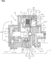
- FIG.2 is a cross-sectional view of the two-stage transmission for the electric vehicle of the first embodiment according to the present invention and the upper portion of the two-stage transmission above a central line L is depicted in FIG.2 .
- the reference numeral 10 indicates a housing and a closed cavity portion, which receives a main portion of the two-stage transmission 4 of the present invention and stores lubricant oil for lubricating engaging portions of the gears, is formed by the housing 10 and a separated cover 10' which is welded to the housing 10.
- the planetary gear mechanism 12 is disposed in the housing 10 and comprises three rotational elements including a carrier 16 which rotatably and pivotally supports plural pinions 14 disposed in a circumferential direction with a space and is sandwiched between the pinions 14, a sun gear 18 whose rotational center is in common with that of the carrier 16 and which is engaged with the pinions 14 at an inside surface, and a ring gear 20 whose rotational center is in common with that of the carrier 16 and which is engaged with the pinions 14 at an outside surface and is configured as inner circumferential gears of the housing 10.
- the reference numeral 22 indicates a needle bearing.
- the two-stage transmission includes an armature 26, a dog clutch 28, a multi-plate friction clutch 30 (hereinafter, referred to as "a friction clutch 30"), an electromagnetic coil 31 which serves as a driving power source for performing a seesaw switching operation between the dog clutch 28 and the friction clutch 30 in one motion, and a support plate 32 to movably support the armature 26, which is used for the seesaw switching operation between the dog clutch 28 and the friction clutch 30, in a fore-aft axial direction.
- the support plate 32 serves as a support portion of a clutch pack of the friction clutch 30 and also has a function that rotational motion received from the electric motor 2 ( FIG.1 ) is transferred to the planetary gear mechanism 12 via the dog clutch 28 or the friction clutch 30.
- the support plate 32 forms a spline 32-1a on an inner circumferential surface of a boss portion 32-1, the boss portion 32-1 is spline-engaged with an output axis (not shown) of the electric motor 2, and the support plate always integrally rotates with the output axis of the electric motor 2.
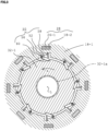
- the dog clutch 28 includes eight fastening units (see, FIG.3 ) which are disposed in a circumferential direction with an equal interval.
- the ring gear 20 of the planetary gear mechanism 12 is integrated with the housing 10, the ring gear 20 is always fixed to the housing 10.
- the sun gear 18 is coupled with the input axis from the electric motor 2 ( FIG. 1 ) via the dog clutch 28 described below and the friction clutch 30 is not engaged, the rotational speed obtained from the carrier 16 which is disposed at the output side is reduced.
- the friction clutch 30 is engaged and the dog clutch 28 is not engaged, the rotation is inputted to and is outputted from the carrier 16 (the gear ratio is 1.0) and the rotational speed obtained from the carrier 16 is relatively increased.
- the carrier 16 includes the spline 16-1a on the inner surface of the boss portion 16-1.
- the input axis (not shown) of the speed reducer 6 ( FIG.1 ) is spline-engaged with the spline 16-1a, resulting in transferring the driving power to the wheels 9 ( FIG.1 ) via the speed reducer 6.
- the armature 26 includes plural clutch projections 26-1 (eight clutch projections are existed in the first embodiment ( FIG.3 )) which are equally spaced in a circumferential direction at an intermediate portion in a radial direction.
- the clutch projections 26-1 serve as a male portion of the respective units in the dog clutch 28.
- the armature 26 also includes a driving portion 44 of the friction clutch 30 in an outer circumferential portion.
- the sun gear 18 of the planetary gear mechanism 12 includes a cylindrical extending portion 18-1 which is extended to the armature 26 side.
- Clutch holes 18-2 (eight clutch holes are existed in the first embodiment ( FIG. 3 )) which are the same number of the clutch projections 26-1 are formed on an armature side flange end portion of this cylindrical extending portion 18-1, and the clutch holes 18-2 are smoothly disengageable to the corresponding clutch projections 26-1 of the armature 26 in an axial direction without looseness.
- the clutch holes 18-2 serve as a female portion of the respective units in the dog clutch 28.
- the eight fastening units of the dog clutch 28 of the first embodiment shown in FIGs.3 and 7 include the clutch projection 26-1 at the armature 26 side and the clutch hole 18-2 at the sun gear 18 side.
- the friction clutch 30 includes an outer cylinder 33 arranged in the housing 10, driven plates 34 which are disposed in sliding grooves 33-1 of the outer cylinder 33 and are slidable in an axial direction, an inner cylinder 36, driving plates 38 which are disposed in sliding grooves 36-1 of the inner cylinder 36 and slidable in an axial direction, clutch facings 40 which are fixed on both surfaces of the driven plates 34, a pressure receiving plate 43 which is disposed on the sliding groove 33-1 of the outer cylinder 33, is slidable in an axial direction and is stopped in an engaged state by a snap ring 42, and a friction clutch driving portion 44 which is integrated with the armature 26 and is opposite to the pressure receiving plate 43.
- a clutch pack is sandwiched between the friction clutch driving portion 44 and the pressure receiving plate 43.
- the friction clutch driving portion 44 sandwiches the clutch pack which includes the driven plates 34, the driving plates 38 and the clutch facings 40, and is opposite to the pressure receiving plate 43.
- the engagement and the disengagement of the friction clutch 30 are performed by the friction clutch driving portion 44 under the axial direction movement of the armature 26.
- the friction clutch driving portion 44 integrally rotates with the armature 26 and a support plate 32.
- an extending portion 26-7 which extends from the armature 26 to the planetary gear mechanism is fit into and is inserted into the support plate 32, and the friction clutch driving portion 44 extends from an end of the extending portion 26-7 to a radial outer circumferential direction.
- the inner cylinder 36 of the friction clutch 30 is configured to be as a cylindrical portion which extends from the support plate 32 to the planetary gear mechanism 12, and integrally rotates with the support plate 32 and the armature 26.
- the support plate 32 is coupled with the input axis from the electric motor 2, and the inner cylinder 36 of the friction clutch 30, which integrally rotates with the support plate 32, also integrally rotates with the input axis.
- the outer cylinder 33 of the friction clutch 30 is coupled with and integrally rotates with the carrier 16.
- the armature 26 is assembled to pivotally support the support plate 32 in an axial direction and not to rotate around the support plate 32 in a circumferential direction. That is, in the first embodiment shown in FIG. 3 , the eight clutch projections 26-1 of the armature 26 side, which are included in the dog clutch 28, are engaged with the corresponding clutch holes 18-2 of the support plate 32 side, resulting in realizing the support structure in which the armature 26 pivotally supports the support plate 32 in an axial direction and does not rotate around the support plate 32 in a circumferential direction.
- the electromagnetic coil 31 of the armature 26 is separately opposite to the planetary gear mechanism 12 and is received in an electromagnetic coil receiving portion 10' -1 formed in the cover 10' .
- the reference numeral 47 indicates a harness for energizing and controlling the electromagnetic coil 31.
- Plural return springs 45 such as coil springs are disposed with a space in a circumferential direction.
- the return springs 45 bias the armature 26 to the left direction in FIG.2 , the clutch projections 26-1 of the armature 26 side and the clutch holes 18-2 of the sun gear 18 side are engaged shown in FIG.2 , the dog clutch 28 becomes the fastening state, the friction clutch driving portion 44 which integrates with the armature 26 is spaced from the clutch pack, and the friction clutch 30 becomes the non-fastening state.
- the seesaw switching operation in which the friction clutch 30 becomes the non-fastening state when the dog clutch 28 becomes the fastening state and the dog clutch 28 becomes the non-fastening state when the friction clutch 30 becomes the fastening state is performed by the left and right direction movements along the rotational axis of the armature 26. It is necessary that the dog clutch 28 and the friction clutch 30 are simultaneously fastened. Considering the required tolerance, when switching between the dog clutch 28 and the friction clutch 30, a state that the output side is separated from the input side, which is so-called as the torque drop, is instantaneously occurred, and this causes the transmission shock which the driver feels.
- the ratchet-type one-way clutch 50 in which the sun gear 18 of the planetary gear mechanism 12 locks to the input axis side, is disposed.
- the ratchet-type one-way clutch 50 is disposed between the cylindrical extending portion 18-1 of the sun gear 18 and the boss portion 32-1 of the support plate 32.
- the ratchet-type one-way clutch which is commercially available includes a unit including an inner race and an outer race.
- the principal structure of the ratchet-type one-way clutch 50 which is disposed between the cylindrical extending portion 18-1 and the boss portion 32-1 is depicted in FIG.3 .
- the ratchet-type one-way clutch 50 of the first embodiment includes eight fastening units ( FIG.3 ) which are the same number of the clutch units of the dog clutch 28 and are disposed in a circumferential direction with an equal interval.
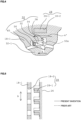
- each of the fastening units of the one-way clutch 50 includes a ratchet craw 52; a ratchet craw receiving portion 54 which is formed as an inner circumferential recess of the cylindrical extending portion 18-1 disposed at an outer circumferential side and receives the ratchet craw 52; a support pin (a pivot pin) 56 which pivotably supports the ratchet craw 52, which is retractable from the ratchet craw receiving portion 54 to the inner circumferential surface of the cylindrical extending portion 18-1, about an axis parallel to the rotational axis "L" ( FIG.2 ) ; a spring 58 such as a coil spring which pivots and biases the ratchet
- the dog clutch 28 includes eight clutch units including the clutch projection 26-1 and the clutch hole 18-2 in a circumferential direction
- the one-way clutch 50 includes the eight units including the ratchet craw 52, the spring 58, the locking groove and so on.
- the fastening operation and the non-fastening operation of the dog clutch 28 and those of the one-way clutch 50 are performed by the same rotational phase. As described below, the above operations lead to the shock reduction when shifting the two-stage transmission according to the first embodiment (speed reduction driving).
- FIG.5 schematically shows a relationship between the clutch projection 26-1 of the dog clutch 28 and the clutch hole 18-2 of the dog clutch 28 in a circumferential direction in the fastening state of the one-way clutch 50 (the fastening state against the locking groove 60 of the ratchet craw 52 shown in FIGs . 3 and 4 ).
- the respective clutch projections 26-1 and clutch holes 18-2 are held at the facing position in a circumferential direction.
- the number of the units of both the dog clutch 28 and the one-way clutch 50 is eight. However, if the units of both the dog clutch 28 and the one-way clutch 50 would become the fastening state at the same rotational phase position, the number of the units of the dog clutch 28 could be different from the number of the units of the one-way clutch 50.
- the rotational driving force in which the rotational speed is reduced to the rotation of the sun gear 18 having the reduction ratio depending on the gear numbers, is transferred to the carrier 16, and the output axis which is spline-fitted into the spline 16-1a by the rotation of the carrier 16 is rotated and is driven by the above rotational driving force.
- the magnetic flux generated in the electromagnetic coil 31 makes the armature move to the rightward direction in FIG. 2 against the elastic force of the return springs 45.
- the clutch projections 26-1 of the dog clutch 28 are completely disengaged from the clutch holes 18-2 of the cylindrical extending portion 18-1 (the sun gear 18), and the dog clutch 28 becomes the non-fastening state.
- the driven plates 34 and the driving plates 38 are sandwiched between the friction clutch driving portion 44 of the armature 26 and the receiving pressure plate 43 via the clutch facings 40, and the friction clutch 30 becomes the fastening state.
- the rotation from the electric motor 2 is transferred from the support plate 32 to the outer cylinder 33 and the carrier 16 via the driving plates 38, the clutch facings 40 and the driven plates 34. Therefore, the output axis which is spline-fit into the spline 16-1a is rotated and is driven by inputting the rotation of the carrier 16, and the output axis and the input axis rotate at the same rotational speed (the gear ratio is 1.0) . That is, since the carrier 16 serves as the input axis and the output axis, the gear ratio which is equal to 1.0 is obtained.
- the sun gear 18 is rotated and is driven by the carrier 16 via the pinions 14, but the sun gear 18 is not directly involved in the transferring of the driving force between the input axis and the output axis.
- the ratchet craw 52 of the one-way clutch 50 is strutted to the sun gear 18 which returns to the reversed direction of the arrow "a" direction
- the cylindrical portion 18-1 (the outer race of the one-way clutch 50) of the sun gear 18 is locked to the boss portion 32-1 (the inner race of the one-way clutch 50) of the support plate 32 which is always coupled with the electric motor rotational axis
- the rotation of the arrow "a" direction of the electric motor rotational axis is transmitted from the boss portion 32-1 of the support plate 32 to the boss portion 18-1 of the sun gear 18, that is, to the wheel side, resulting in not occurring the torque drop.
- the ratchet craw 52 can climb over the locking groove 60 even when the centrifugal force is smaller than the spring force, and the sun gear 18 enables to increase the rotational number. Then, when the friction clutch 30 completely becomes the fastening state and the rotational number of the sun gear 18 becomes higher, as shown in the imaginary line 52a of FIG.
- the ratchet craw 52 rotates around the pin 56 in a radial outward direction and is disengaged from the locking groove 60.
- the ratchet craw 52 is disengaged from the locking groove 60 (when the one-way clutch 50 becomes the unlocked state)
- the relative rotation between the outer race (the cylindrical extending portion 18-1 of the sun gear 18) and the inner race (the boss portion 32-1 of the support plate 32) is occurred and then the rotational phase of the ratchet 52 to the locking groove 60 becomes uncertain.
- the inverse operation is performed in the shifting process from the high vehicle speed driving (the second speed) to the low vehicle speed driving (the first speed) .
- the ratchet craw 52 of the one-way clutch 50 is engaged with the locking groove 60 under the bias force of the spring 58 by the relative rotation and the one-way clutch 50 becomes the fastening state.
- the friction clutch 30 becomes the non-fastening state and the armature 26 is driven by the springs 45 such that the dog clutch 28 is to be engaged.
- the shifting from the high vehicle speed driving (the second speed) to the low vehicle speed driving (the first speed) is performed in a state that the ratchet-type one-way clutch 50 is engaged, as described with respect to FIG.5 , the rotational phase of the clutch projection 26-1 of the dog clutch 28 is coincident with that of the clutch hole 18-2 of the dog clutch 28 in shifting and the clutch projection 26-1 is instantaneously engaged with the clutch hole 18-2 just after the intermediate state that both the friction clutch 30 and the dog clutch 28 are in the non-fastening state is terminated.
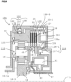
- FIGs.8 , 9 and 10 show the two-stage transmission 104 of the second embodiment according to the present invention, in which the countermeasure against the torque drop occurring in shifting between the low vehicle speed driving and the high vehicle speed driving is implemented.
- the ring gear 120 of the planetary gear mechanism 112 not only is rotatable to the housing 10, but also is selectively fixed to the housing 10 by the one-way clutch 150.
- the low vehicle speed driving is performed by the speed reduction driving in which the ring gear is fixed and the gear ratio is 2.4
- the high vehicle speed driving is performed by the uniform speed driving in which the sun gear 18 integrally rotates with the ring gear 120 and the gear ratio is 1.0.
- the armature 126 includes the cylindrical portion 126a at the intermediate position in a radial direction, the cylindrical portion 126a includes an inner tooth 126-1 in a circumferential direction, an outer tooth 10'-2 in a circumferential direction is formed on the cover 10' which is fixed to the housing 10, and the dog clutch 128 is constituted by the inner tooth 126-1 and the outer tooth 10'-2.
- the driving portion 144 of the friction clutch 130 is constituted by the outer portion of the armature 126, the outer tooth 126-5 is formed on the outer circumference of the armature 126 and pivotably engages with the sliding groove 33-1 of the inner cylinder 33 in an axial direction.
- an electromagnet holding frame 82 is fixed to the cover 10' .
- the inner spline 18-3 of the sun gear 18 is spline-fit into the electric motor rotational axis (not shown) and the rotation driving force by the electric motor 2 is transferred to the sun gear 18.
- the rear-end cylindrical portion 18-4 of the sun gear 18 is the inner cylinder of the friction clutch 130 in the second embodiment and the driving plates 38 are disposed in the inner cylinder of the friction clutch 130.
- the carrier 16 is spline-fit into the output axis of the wheel side by the inner spline 16-1a.
- the ratchet-type one-way clutch 150 for preventing the torque drop in speed shifting between the first speed and the second speed is disposed between the ring gear 120 (in a schematic view of FIG.8 , the ring gear 120 serves as the inner race of the one-way clutch 150) and the housing 10 (in a schematic view of FIG.8 , the housing 10 serves as the outer race of the one-way clutch 150).
- the assembled direction of the ratchet craw 152 of the one-way clutch 150 of the second embodiment is reversed to that of the first embodiment.
- the electromagnetic coil 31 is not energized, the armature 126 is pressed toward the cover 10' in FIG.8 by the springs 45, the inner tooth 126-1 of the armature 126 is engaged with the outer tooth 10'-2 of the cover10', the dog clutch 128 is the fastening state (the friction clutch 130 is the non-fastening state), and then the armature 126 is fixed.
- the outer tooth 126-5 formed on the outer circumferential edge of the armature 126 is engaged with the outer cylinder 33 of the friction clutch 130 via the sliding groove 33-1 and therefore the ring gear 120 is fixed to the cover 10', that is, the housing 10.
- the rotation of the electric motor rotational axis is transferred to the carrier 16, the gear ratio is 2.4 as well as the first embodiment, the rotational speed of the carrier 16 is reduced and both the inner race side (120) and the outer race side (10) of the one-way clutch 150 are still fixed.
- the function there is no difference between a case that the one-way clutch 150 is disposed and a case that the one-way clutch 150 is not disposed. Since the one-way clutch 150 is attached to (is fixed to) the housing 10 side, the centrifugal force is not operated to the spring 158.
- the spring 158 functions only to engage with the locking groove 160 and thus the spring force of the spring 158 may be very small.
- the electromagnetic coil 31 is energized, as shown in FIG.10 , the armature 126 moves to the leftward direction by the electromagnetic force against the springs 45, the engagement between the inner tooth 126-1 of the armature 126 and the outer tooth 10'-2 of the cover 10' is released and the dog clutch 128 becomes the non-fastening state.
- the clutch pack is sandwiched between the friction clutch driving portion 144 and the facing surface of the ring gear 120 and then the friction clutch 130 becomes the fastening state.
- the ring gear 120 and the sun gear 18 are integrated by the friction clutch 130.
- the carrier 16, the ring gear 120 and the sun gear 18 integrally rotate and the rotation of the input side is transferred to the output side on one-to-one basis.
- the ring gear 120 rotates over the ratchet craw 152 at the locking groove 160 against the spring 158.
- the spring force of the spring 158 is very small, rotational resistance by the friction is substantially omitted.
- the ratchet craw 152 of the one-way clutch 150 functions to lock such a movement, that is, the locking against the housing 10 of the ring gear 120 is continued, the rotation of the rotational axis of the electric motor 2 is transferred to the wheel side via the sun gear 18 and the carrier 16, resulting in preventing the torque drop.
- the friction clutch 130 is completely the fastening state, the rotation of the ring gear 120 is transferred to the wheel side with the same rotation direction as that of the rotational axis of the electric motor 2 (the arrow "a") and the gear ratio whose value is 1.0. Since this rotational direction is the direction in which the ring gear 120 rotates over the locking groove 160 of the ratchet craw 152, the rotation of the ring gear 120 remains robust.
- the gear ratio in the planetary gear mechanism is explained in the embodiments that the speed reduction (the first speed) in which the ring gear is fixed and the relatively speed increase (the second speed) in which the three rotational elements integrally rotate are realized.
- the speed reducer FIG. 1
- the modified configuration that the relative speed reduction (the first speed) in which the three rotational elements of the planetary gear mechanism integrally rotate and the speed increase (the second speed) in which the sun gear is fixed can easily be conceived, and it is obvious for those skilled in the art that the above configuration is also included in the present invention.
- the two-stage transmission according to the present invention can be adapted to not only the electric vehicle (EV) but also the hybrid vehicle.
Landscapes
- Engineering & Computer Science (AREA)
- General Engineering & Computer Science (AREA)
- Mechanical Engineering (AREA)
- Structure Of Transmissions (AREA)
Claims (3)
- Fahrzeug, umfassend einen Elektromotor (2) zum Antreiben von Rädern und ein Zweiganggetriebe (4, 104), das entlang einer Kraftabgabeachse des Elektromotors (2) angeordnet ist, wobei das Zweiganggetriebe umfasst:einen Planetengetriebemechanismus (12), der drei Rotationselemente (16, 18, 20; 16, 18, 120) umfasst, einschließlich eines Trägers (16), der mehrere Ritzel (14) schwenkbar stützt, und einschließlich mehrerer Zahnräder (16, 18), die eine unterschiedliche Zähneanzahl aufweisen und mit den Ritzeln (14) im Eingriff stehen;und wobei der Planetengetriebemechanismus (12) umfasst:einen ersten Geschwindigkeitsmodus, in dem ein erstes Rotationselement (20, 120), das aus den drei Rotationselementen (16, 18, 20; 16, 18, 120) ausgewählt ist, an einer Gehäuseseite (10) befestigt ist und eine Kraftübertragung unter Verwendung eines Übersetzungsverhältnisses durchgeführt wird, dessen Wert von 1,0 verschieden ist und das zwischen einem zweiten Rotationselement (18) und einem dritten Rotationselement (16) erhalten wird,und einen zweiten Geschwindigkeitsmodus, in dem die Kraftübertragung unter Verwendung eines Übersetzungsverhältnisses durchgeführt wird, dessen Wert 1,0 ist und das dadurch erhalten wird, dass das erste Rotationselement (20) an einer Gehäuseseite (10) befestigt ist und dass eine Rotation der Kraftabgabeachse des Elektromotors (2) in eines (16) des zweiten Rotationselements (18) und des dritten Rotationselements (16) eingegeben wird, und die Rotation von dem einen Rotationselement (16) abgegeben wird; oder dass das erste Rotationselement (120) nicht an der Gehäuseseite (10') befestigt ist und eines des zweiten Rotationselements (18) und des dritten Rotationselements (16) integral mit dem ersten Rotationselement (120) gedreht wird;eine Klauenkupplung (28; 128), die mit dem zweiten Rotationselement (18) des Planetengetriebemechanismus (12) gekoppelt werden kann, um einen Geschwindigkeitsmodus mit einer Seite mit relativ niedrigem Übersetzungsverhältnis unter dem ersten Geschwindigkeitsmodus und dem zweiten Geschwindigkeitsmodus auszuwählen;eine Reibungskupplung (30), die mit dem dritten Rotationselement (16) des Planetengetriebemechanismus (12) gekoppelt werden kann, um einen Geschwindigkeitsmodus mit einer Seite mit relativ hohem Übersetzungsverhältnis unter dem ersten Geschwindigkeitsmodus und dem zweiten Geschwindigkeitsmodus auszuwählen; undeine Einweg-Klinkenkupplung (50; 150), um einen Drehmomentabfall beim Schalten zwischen dem ersten Geschwindigkeitsmodus und dem zweiten Geschwindigkeitsmodus zu verhindern,wobei Eingriffnahmeabschnitte (18-2, 26-1) der Klauenkupplung (28; 128) und Klinkeneingriffnahmeabschnitte (52) der Einweg-Klinkenkupplung (50; 150) an derselben Rotationsphasenposition angeordnet sind.
- Fahrzeug nach Anspruch 1,wobei das erste Rotationselement (20) dauerhaft an der Gehäuseseite (10) befestigt ist,wobei der erste Geschwindigkeitsmodus, in dem ein untersetzungsgeschwindigkeitsseitiges Übersetzungsverhältnis, dessen Wert größer als 1,0 ist, zwischen dem zweiten Rotationselement (18) und dem dritten Rotationselement (16) unter Verwendung der Klauenkupplung (28) erhalten wird, als der Geschwindigkeitsmodus mit einer Seite mit relativ niedrigem Übersetzungsverhältnis dient,wobei der zweite Geschwindigkeitsmodus, in dem ein Übersetzungsverhältnis, dessen Wert 1,0 ist, durch Eingeben von einem des zweiten Rotationselements (18) und des dritten Rotationselement (16) des Planetengetriebemechanismus (12) unter Verwendung der Reibungskupplung (30) und Abgeben an eines des zweiten Rotationselements (18) und des dritten Rotationselement (16) des Planetengetriebemechanismus (12) unter Verwendung der Reibungskupplung (30) erhalten wird, als der Geschwindigkeitsmodus mit einer Seite mit relativ hohem Übersetzungsverhältnis dient, undwobei, wenn zwischen dem ersten Geschwindigkeitsmodus und dem zweiten Geschwindigkeitsmodus umgeschaltet wird, die Einweg-Klinkenkupplung (50) den Drehmomentabfall verhindert, indem sie das eine (16) des zweiten Rotationselements (18) oder des dritten Rotationselements (16) mit einer Krafteingabeachsenseite (31-1a) so verriegelt, dass eine Kraftübertragung von einer Krafteingabeseite (32-1a) zu einer Kraftabgabeseite (16-1a) ohne Drehmomentabfall durchgeführt wird.
- Fahrzeug nach Anspruch 1,wobei das erste Rotationselement (120) selektiv an der Gehäuseseite (10'-2) befestigt ist,wobei der erste Geschwindigkeitsmodus, in dem das erste Rotationselement (120) an der Gehäuseseite (10'-2) befestigt ist und ein Übersetzungsverhältnis, dessen Wert größer als 1,0 ist und das ein untersetzungsgeschwindigkeitsseitiges Übersetzungsverhältnis ist, zwischen dem zweiten Rotationselement (18) und dem dritten Rotationselement (16) unter Verwendung der Klauenkupplung (128) erhalten wird, als der Geschwindigkeitsmodus mit einer Seite mit relativ niedrigem Übersetzungsverhältnis dient,wobei der zweite Geschwindigkeitsmodus, in dem das erste Rotationselement (120) aus der Befestigung an der Gehäuseseite (10'-2) gelöst ist und ein Übersetzungsverhältnis, dessen Wert 1,0 ist, durch integrales Rotieren eines des zweiten Rotationselements (18) und des dritten Rotationselements (16) mit dem ersten Rotationselement (120) unter Verwendung der Reibungskupplung (130) erhalten wird, als der Geschwindigkeitsmodus mit einer Seite mit relativ hohem Übersetzungsverhältnis dient, undwobei die Einweg-Klinkenkupplung (50) den Drehmomentabfall verhindert, indem sie das erste Rotationselement (120) mit der Gehäuseseite (10'-2) so verriegelt, dass die Kraftübertragung von einer Krafteingabeseite (18-3) zu einer Kraftabgabeseite (16-1) ohne Drehmomentabfall durchgeführt wird.
Applications Claiming Priority (2)
| Application Number | Priority Date | Filing Date | Title |
|---|---|---|---|
| JP2019130088 | 2019-07-12 | ||
| PCT/JP2020/025233 WO2021010138A1 (ja) | 2019-07-12 | 2020-06-26 | 電動駆動車用2段変速機 |
Publications (3)
| Publication Number | Publication Date |
|---|---|
| EP3889464A1 EP3889464A1 (de) | 2021-10-06 |
| EP3889464A4 EP3889464A4 (de) | 2022-09-28 |
| EP3889464B1 true EP3889464B1 (de) | 2025-01-22 |
Family
ID=74210696
Family Applications (1)
| Application Number | Title | Priority Date | Filing Date |
|---|---|---|---|
| EP20840259.4A Active EP3889464B1 (de) | 2019-07-12 | 2020-06-26 | Zweistufiges getriebe für ein elektrisch angetriebenes fahrzeug |
Country Status (5)
| Country | Link |
|---|---|
| US (1) | US11408488B2 (de) |
| EP (1) | EP3889464B1 (de) |
| JP (1) | JP7427670B2 (de) |
| CN (1) | CN113412379B (de) |
| WO (1) | WO2021010138A1 (de) |
Families Citing this family (2)
| Publication number | Priority date | Publication date | Assignee | Title |
|---|---|---|---|---|
| KR102402872B1 (ko) * | 2021-09-29 | 2022-05-30 | 이엠티씨 주식회사 | 변속충격이 저감된 원심클러치와 이를 구비한 변속장치 |
| DE102022209300B3 (de) | 2022-09-07 | 2023-08-03 | Magna Pt B.V. & Co. Kg | Klauenkupplung mit Freilauffunktion und Antriebsanordnung |
Family Cites Families (9)
| Publication number | Priority date | Publication date | Assignee | Title |
|---|---|---|---|---|
| JP3184230B2 (ja) * | 1990-12-28 | 2001-07-09 | 株式会社シマノ | 内装変速機 |
| FR2817009B1 (fr) * | 2000-11-17 | 2003-01-24 | Antonov Automotive Europ | Dispositif de transmission, notamment pour vehicule terrestre |
| JP2006234062A (ja) * | 2005-02-24 | 2006-09-07 | Ishikawajima Harima Heavy Ind Co Ltd | 正逆転可能な2段変速機 |
| DE102011083202A1 (de) * | 2011-09-22 | 2013-03-28 | Schaeffler Technologies AG & Co. KG | Antriebseinheit mit einem Elektromotor |
| JP2013133841A (ja) | 2011-12-26 | 2013-07-08 | Honda Motor Co Ltd | 変速機 |
| KR20160005209A (ko) | 2014-07-04 | 2016-01-14 | 현대자동차주식회사 | 자동차용 2단 변속기 |
| JP6517502B2 (ja) | 2014-12-02 | 2019-05-22 | 株式会社Ihiエアロスペース | 二段変速機 |
| DE102015116537B4 (de) * | 2015-09-30 | 2022-10-20 | Dr. Ing. H.C. F. Porsche Aktiengesellschaft | Elektrischer Achsantrieb für ein Kraftfahrzeug |
| EP3805607A4 (de) * | 2018-06-02 | 2022-03-02 | Unipres Corporation | Zweistufiges getriebe für ein elektrofahrzeug |
-
2020
- 2020-06-26 JP JP2021532760A patent/JP7427670B2/ja active Active
- 2020-06-26 EP EP20840259.4A patent/EP3889464B1/de active Active
- 2020-06-26 US US17/420,175 patent/US11408488B2/en active Active
- 2020-06-26 WO PCT/JP2020/025233 patent/WO2021010138A1/ja not_active Ceased
- 2020-06-26 CN CN202080013099.2A patent/CN113412379B/zh active Active
Also Published As
| Publication number | Publication date |
|---|---|
| JP7427670B2 (ja) | 2024-02-05 |
| US20220128129A1 (en) | 2022-04-28 |
| EP3889464A1 (de) | 2021-10-06 |
| JPWO2021010138A1 (de) | 2021-01-21 |
| CN113412379B (zh) | 2023-10-13 |
| WO2021010138A1 (ja) | 2021-01-21 |
| EP3889464A4 (de) | 2022-09-28 |
| CN113412379A (zh) | 2021-09-17 |
| US11408488B2 (en) | 2022-08-09 |
Similar Documents
| Publication | Publication Date | Title |
|---|---|---|
| EP3828437B1 (de) | Mehrganggetriebe und damit hergestellte antriebsachse | |
| CN112534161B (zh) | 差速器断开组件 | |
| US8684122B2 (en) | Power assisted bicycle with regenerative function | |
| US6905009B2 (en) | Bi-directional clutch having a momentary latching actuator | |
| CN112204271B (zh) | 电动汽车用二级变速器 | |
| EP3805607A1 (de) | Zweistufiges getriebe für ein elektrofahrzeug | |
| JP2005240861A (ja) | 電磁制御式差動制限装置 | |
| EP3889464A1 (de) | Zweistufiges getriebe für ein elektrisch angetriebenes fahrzeug | |
| CN114439864B (zh) | 电驱动装置离合器 | |
| CN104847890A (zh) | 用于驱动模块的驻车锁 | |
| EP4249305B1 (de) | Trenndifferential und elektrisches antriebsübertragungssystem damit | |
| JP6648173B2 (ja) | 車両用駆動装置 | |
| US20110136610A1 (en) | Actuator for operating a differential lock | |
| US11015666B2 (en) | Selectable torque transfer mechanism for a vehicle transmission | |
| JP7672773B2 (ja) | 駆動装置 | |
| CN220816339U (zh) | 断开模块、车辆的动力传动系统以及车辆 | |
| EP3055587B1 (de) | Automatikgetriebe | |
| JP2007333133A (ja) | デファレンシャル装置 | |
| US20260085729A1 (en) | Jaw clutch having a freewheeling function, and drive assembly | |
| JP2801731B2 (ja) | デファレンシャル装置 | |
| JP2007139147A (ja) | 駆動力伝達装置 | |
| JP2025159527A (ja) | 駆動ユニット、及び変速装置 | |
| CN119604703A (zh) | 单元 | |
| CN119384568A (zh) | 车辆用驱动力传递装置 | |
| CN119554340A (zh) | 断开模块、车辆的动力传动系统以及车辆 |
Legal Events
| Date | Code | Title | Description |
|---|---|---|---|
| STAA | Information on the status of an ep patent application or granted ep patent |
Free format text: STATUS: THE INTERNATIONAL PUBLICATION HAS BEEN MADE |
|
| PUAI | Public reference made under article 153(3) epc to a published international application that has entered the european phase |
Free format text: ORIGINAL CODE: 0009012 |
|
| STAA | Information on the status of an ep patent application or granted ep patent |
Free format text: STATUS: REQUEST FOR EXAMINATION WAS MADE |
|
| 17P | Request for examination filed |
Effective date: 20210702 |
|
| AK | Designated contracting states |
Kind code of ref document: A1 Designated state(s): AL AT BE BG CH CY CZ DE DK EE ES FI FR GB GR HR HU IE IS IT LI LT LU LV MC MK MT NL NO PL PT RO RS SE SI SK SM TR |
|
| A4 | Supplementary search report drawn up and despatched |
Effective date: 20220829 |
|
| RIC1 | Information provided on ipc code assigned before grant |
Ipc: F16H 61/04 20060101ALI20220823BHEP Ipc: F16H 3/54 20060101AFI20220823BHEP |
|
| DAV | Request for validation of the european patent (deleted) | ||
| DAX | Request for extension of the european patent (deleted) | ||
| STAA | Information on the status of an ep patent application or granted ep patent |
Free format text: STATUS: EXAMINATION IS IN PROGRESS |
|
| 17Q | First examination report despatched |
Effective date: 20240529 |
|
| GRAP | Despatch of communication of intention to grant a patent |
Free format text: ORIGINAL CODE: EPIDOSNIGR1 |
|
| STAA | Information on the status of an ep patent application or granted ep patent |
Free format text: STATUS: GRANT OF PATENT IS INTENDED |
|
| INTG | Intention to grant announced |
Effective date: 20241011 |
|
| GRAS | Grant fee paid |
Free format text: ORIGINAL CODE: EPIDOSNIGR3 |
|
| GRAA | (expected) grant |
Free format text: ORIGINAL CODE: 0009210 |
|
| STAA | Information on the status of an ep patent application or granted ep patent |
Free format text: STATUS: THE PATENT HAS BEEN GRANTED |
|
| AK | Designated contracting states |
Kind code of ref document: B1 Designated state(s): AL AT BE BG CH CY CZ DE DK EE ES FI FR GB GR HR HU IE IS IT LI LT LU LV MC MK MT NL NO PL PT RO RS SE SI SK SM TR |
|
| REG | Reference to a national code |
Ref country code: GB Ref legal event code: FG4D |
|
| REG | Reference to a national code |
Ref country code: CH Ref legal event code: EP |
|
| REG | Reference to a national code |
Ref country code: IE Ref legal event code: FG4D |
|
| REG | Reference to a national code |
Ref country code: DE Ref legal event code: R096 Ref document number: 602020045272 Country of ref document: DE |
|
| REG | Reference to a national code |
Ref country code: NL Ref legal event code: MP Effective date: 20250122 |
|
| PG25 | Lapsed in a contracting state [announced via postgrant information from national office to epo] |
Ref country code: NL Free format text: LAPSE BECAUSE OF FAILURE TO SUBMIT A TRANSLATION OF THE DESCRIPTION OR TO PAY THE FEE WITHIN THE PRESCRIBED TIME-LIMIT Effective date: 20250122 |
|
| PG25 | Lapsed in a contracting state [announced via postgrant information from national office to epo] |
Ref country code: RS Free format text: LAPSE BECAUSE OF FAILURE TO SUBMIT A TRANSLATION OF THE DESCRIPTION OR TO PAY THE FEE WITHIN THE PRESCRIBED TIME-LIMIT Effective date: 20250422 |
|
| PG25 | Lapsed in a contracting state [announced via postgrant information from national office to epo] |
Ref country code: FI Free format text: LAPSE BECAUSE OF FAILURE TO SUBMIT A TRANSLATION OF THE DESCRIPTION OR TO PAY THE FEE WITHIN THE PRESCRIBED TIME-LIMIT Effective date: 20250122 |
|
| PG25 | Lapsed in a contracting state [announced via postgrant information from national office to epo] |
Ref country code: PL Free format text: LAPSE BECAUSE OF FAILURE TO SUBMIT A TRANSLATION OF THE DESCRIPTION OR TO PAY THE FEE WITHIN THE PRESCRIBED TIME-LIMIT Effective date: 20250122 |
|
| PGFP | Annual fee paid to national office [announced via postgrant information from national office to epo] |
Ref country code: DE Payment date: 20250521 Year of fee payment: 6 |
|
| PG25 | Lapsed in a contracting state [announced via postgrant information from national office to epo] |
Ref country code: ES Free format text: LAPSE BECAUSE OF FAILURE TO SUBMIT A TRANSLATION OF THE DESCRIPTION OR TO PAY THE FEE WITHIN THE PRESCRIBED TIME-LIMIT Effective date: 20250122 |
|
| REG | Reference to a national code |
Ref country code: LT Ref legal event code: MG9D |
|
| PG25 | Lapsed in a contracting state [announced via postgrant information from national office to epo] |
Ref country code: IS Free format text: LAPSE BECAUSE OF FAILURE TO SUBMIT A TRANSLATION OF THE DESCRIPTION OR TO PAY THE FEE WITHIN THE PRESCRIBED TIME-LIMIT Effective date: 20250522 Ref country code: NO Free format text: LAPSE BECAUSE OF FAILURE TO SUBMIT A TRANSLATION OF THE DESCRIPTION OR TO PAY THE FEE WITHIN THE PRESCRIBED TIME-LIMIT Effective date: 20250422 |
|
| REG | Reference to a national code |
Ref country code: AT Ref legal event code: MK05 Ref document number: 1761676 Country of ref document: AT Kind code of ref document: T Effective date: 20250122 |
|
| PG25 | Lapsed in a contracting state [announced via postgrant information from national office to epo] |
Ref country code: HR Free format text: LAPSE BECAUSE OF FAILURE TO SUBMIT A TRANSLATION OF THE DESCRIPTION OR TO PAY THE FEE WITHIN THE PRESCRIBED TIME-LIMIT Effective date: 20250122 |
|
| PG25 | Lapsed in a contracting state [announced via postgrant information from national office to epo] |
Ref country code: PT Free format text: LAPSE BECAUSE OF FAILURE TO SUBMIT A TRANSLATION OF THE DESCRIPTION OR TO PAY THE FEE WITHIN THE PRESCRIBED TIME-LIMIT Effective date: 20250522 Ref country code: LV Free format text: LAPSE BECAUSE OF FAILURE TO SUBMIT A TRANSLATION OF THE DESCRIPTION OR TO PAY THE FEE WITHIN THE PRESCRIBED TIME-LIMIT Effective date: 20250122 |
|
| PG25 | Lapsed in a contracting state [announced via postgrant information from national office to epo] |
Ref country code: BG Free format text: LAPSE BECAUSE OF FAILURE TO SUBMIT A TRANSLATION OF THE DESCRIPTION OR TO PAY THE FEE WITHIN THE PRESCRIBED TIME-LIMIT Effective date: 20250122 Ref country code: GR Free format text: LAPSE BECAUSE OF FAILURE TO SUBMIT A TRANSLATION OF THE DESCRIPTION OR TO PAY THE FEE WITHIN THE PRESCRIBED TIME-LIMIT Effective date: 20250423 |
|
| PG25 | Lapsed in a contracting state [announced via postgrant information from national office to epo] |
Ref country code: AT Free format text: LAPSE BECAUSE OF FAILURE TO SUBMIT A TRANSLATION OF THE DESCRIPTION OR TO PAY THE FEE WITHIN THE PRESCRIBED TIME-LIMIT Effective date: 20250122 |
|
| PG25 | Lapsed in a contracting state [announced via postgrant information from national office to epo] |
Ref country code: SE Free format text: LAPSE BECAUSE OF FAILURE TO SUBMIT A TRANSLATION OF THE DESCRIPTION OR TO PAY THE FEE WITHIN THE PRESCRIBED TIME-LIMIT Effective date: 20250122 |
|
| PG25 | Lapsed in a contracting state [announced via postgrant information from national office to epo] |
Ref country code: SM Free format text: LAPSE BECAUSE OF FAILURE TO SUBMIT A TRANSLATION OF THE DESCRIPTION OR TO PAY THE FEE WITHIN THE PRESCRIBED TIME-LIMIT Effective date: 20250122 |
|
| PG25 | Lapsed in a contracting state [announced via postgrant information from national office to epo] |
Ref country code: DK Free format text: LAPSE BECAUSE OF FAILURE TO SUBMIT A TRANSLATION OF THE DESCRIPTION OR TO PAY THE FEE WITHIN THE PRESCRIBED TIME-LIMIT Effective date: 20250122 |
|
| PG25 | Lapsed in a contracting state [announced via postgrant information from national office to epo] |
Ref country code: IT Free format text: LAPSE BECAUSE OF FAILURE TO SUBMIT A TRANSLATION OF THE DESCRIPTION OR TO PAY THE FEE WITHIN THE PRESCRIBED TIME-LIMIT Effective date: 20250122 |
|
| PG25 | Lapsed in a contracting state [announced via postgrant information from national office to epo] |
Ref country code: CZ Free format text: LAPSE BECAUSE OF FAILURE TO SUBMIT A TRANSLATION OF THE DESCRIPTION OR TO PAY THE FEE WITHIN THE PRESCRIBED TIME-LIMIT Effective date: 20250122 Ref country code: EE Free format text: LAPSE BECAUSE OF FAILURE TO SUBMIT A TRANSLATION OF THE DESCRIPTION OR TO PAY THE FEE WITHIN THE PRESCRIBED TIME-LIMIT Effective date: 20250122 |
|
| REG | Reference to a national code |
Ref country code: DE Ref legal event code: R097 Ref document number: 602020045272 Country of ref document: DE |
|
| PG25 | Lapsed in a contracting state [announced via postgrant information from national office to epo] |
Ref country code: RO Free format text: LAPSE BECAUSE OF FAILURE TO SUBMIT A TRANSLATION OF THE DESCRIPTION OR TO PAY THE FEE WITHIN THE PRESCRIBED TIME-LIMIT Effective date: 20250122 |
|
| PG25 | Lapsed in a contracting state [announced via postgrant information from national office to epo] |
Ref country code: SK Free format text: LAPSE BECAUSE OF FAILURE TO SUBMIT A TRANSLATION OF THE DESCRIPTION OR TO PAY THE FEE WITHIN THE PRESCRIBED TIME-LIMIT Effective date: 20250122 |
|
| PLBE | No opposition filed within time limit |
Free format text: ORIGINAL CODE: 0009261 |
|
| STAA | Information on the status of an ep patent application or granted ep patent |
Free format text: STATUS: NO OPPOSITION FILED WITHIN TIME LIMIT |
|
| REG | Reference to a national code |
Ref country code: CH Ref legal event code: L10 Free format text: ST27 STATUS EVENT CODE: U-0-0-L10-L00 (AS PROVIDED BY THE NATIONAL OFFICE) Effective date: 20251203 |
|
| 26N | No opposition filed |
Effective date: 20251023 |
|
| REG | Reference to a national code |
Ref country code: CH Ref legal event code: H13 Free format text: ST27 STATUS EVENT CODE: U-0-0-H10-H13 (AS PROVIDED BY THE NATIONAL OFFICE) Effective date: 20260127 |
|
| PG25 | Lapsed in a contracting state [announced via postgrant information from national office to epo] |
Ref country code: MC Free format text: LAPSE BECAUSE OF FAILURE TO SUBMIT A TRANSLATION OF THE DESCRIPTION OR TO PAY THE FEE WITHIN THE PRESCRIBED TIME-LIMIT Effective date: 20250122 |
|
| PG25 | Lapsed in a contracting state [announced via postgrant information from national office to epo] |
Ref country code: LU Free format text: LAPSE BECAUSE OF NON-PAYMENT OF DUE FEES Effective date: 20250626 |
|
| GBPC | Gb: european patent ceased through non-payment of renewal fee |
Effective date: 20250626 |
|
| REG | Reference to a national code |
Ref country code: BE Ref legal event code: MM Effective date: 20250630 |
|
| PG25 | Lapsed in a contracting state [announced via postgrant information from national office to epo] |
Ref country code: GB Free format text: LAPSE BECAUSE OF NON-PAYMENT OF DUE FEES Effective date: 20250626 |
|
| PG25 | Lapsed in a contracting state [announced via postgrant information from national office to epo] |
Ref country code: IE Free format text: LAPSE BECAUSE OF NON-PAYMENT OF DUE FEES Effective date: 20250626 |
|
| PG25 | Lapsed in a contracting state [announced via postgrant information from national office to epo] |
Ref country code: BE Free format text: LAPSE BECAUSE OF NON-PAYMENT OF DUE FEES Effective date: 20250630 |
|
| PG25 | Lapsed in a contracting state [announced via postgrant information from national office to epo] |
Ref country code: FR Free format text: LAPSE BECAUSE OF NON-PAYMENT OF DUE FEES Effective date: 20250630 |
|
| PG25 | Lapsed in a contracting state [announced via postgrant information from national office to epo] |
Ref country code: CH Free format text: LAPSE BECAUSE OF NON-PAYMENT OF DUE FEES Effective date: 20250630 |