EP3889369B1 - Verstärkungselement für beton - Google Patents
Verstärkungselement für beton Download PDFInfo
- Publication number
- EP3889369B1 EP3889369B1 EP20213285.8A EP20213285A EP3889369B1 EP 3889369 B1 EP3889369 B1 EP 3889369B1 EP 20213285 A EP20213285 A EP 20213285A EP 3889369 B1 EP3889369 B1 EP 3889369B1
- Authority
- EP
- European Patent Office
- Prior art keywords
- concrete
- reinforcing elements
- fibres
- reinforcing
- resin
- Prior art date
- Legal status (The legal status is an assumption and is not a legal conclusion. Google has not performed a legal analysis and makes no representation as to the accuracy of the status listed.)
- Active
Links
Images


Classifications
-
- E—FIXED CONSTRUCTIONS
- E04—BUILDING
- E04C—STRUCTURAL ELEMENTS; BUILDING MATERIALS
- E04C5/00—Reinforcing elements, e.g. for concrete; Auxiliary elements therefor
- E04C5/07—Reinforcing elements of material other than metal, e.g. of glass, of plastics, or not exclusively made of metal
- E04C5/073—Discrete reinforcing elements, e.g. fibres
Definitions
- the present invention relates to a reinforcing element for concrete, wherein this reinforcing element comprises a bundle of resin-impregnated fibres.
- the present invention also relates to an assembly of such reinforcing elements and concrete comprising reinforcing elements.
- the present invention also relates to concrete comprising reinforcing elements and a method for manufacturing a concrete construction.
- reinforcing elements for concrete.
- relatively large elements made from steel such as steel wire, steel reinforcement mats, etc.
- steel fibres By means of steel fibres, it is also possible to give the concrete a certain degree of strength, but the use of steel fibres also has drawbacks.
- these steel fibres are inter alia prone to corrosion at the level of the concrete surface and the specific weight of steel fibres is greater than that of concrete.
- steel fibres are less readily mixable with concrete, so that the distribution of steel fibres in the concrete is usually not uniform.
- WO 2012/053901 A1 discloses a reinforcing element for concrete, wherein this reinforcing element comprises a bundle of fibres made of basalt, carbon, glass fiber or the like embedded in a cured matrix, wherein the reinforcing element successively comprises a first end section, a central section and a second end section, wherein the bundle of fibres is twisted in the central section.
- WO 98/31891 A1 discloses a bar for reinforcing purposes formed by drawing longitudinally extending resin-impregnated fibres through forming eyes to remove excess resin, leaving an external surface which is non-smooth in appearance. The roughened surface will tend to grip well within the material being reinforced.
- FR 1 366 610 A discloses reinforcement elements for concrete in the form of rectilinear rods, resistant to bending, being made of metal or plastic material.
- WO 2017/171668 A1 discloses a macro synthetic fiber based reinforcement material for concrete, which is a cord in form of twisted yarn(s) comprising a twisted fiber comprising polyamide 6 or polyamide 6,6.
- this object is achieved by providing a reinforcing element for concrete according to claim 1, wherein this reinforcing element comprises a bundle of resin-impregnated fibres, wherein the reinforcing element successively comprises a first end section, a central section and a second end section, wherein the bundle of fibres is twisted in the central section.
- this reinforcing element only consists of a first end section, a central section and a second end section.
- the bundle of fibres comprises plastic fibres, glass fibres, basalt fibres, flax fibres or carbon fibres or a mixture of two or more of the abovementioned fibres.
- the central section which in this case is twisted, extends between the two abovementioned end sections.
- the bundle of fibres is not twisted, or only to a minimal degree, at the position of said two end sections. Due to the central section being twisted, the fibres are under tension here and, in addition, due to the specific design of these reinforcing elements, in which the twisted central section is clamped between said two end sections, the central section will readily be able to absorb tensile stress in the concrete and these reinforcing elements will not only be able to withstand the formation of cracks, but will also contribute significantly to the strength of the concrete.
- the bundle of fibres preferably comprises glass fibres.
- the bundle of fibres is twisted in the central section.
- the bundle of fibres is turned in a specific direction of rotation and the bundle of fibres is thus twisted.
- a reinforcing element can easily be formed by starting with a bundle of fibres, in which case all the fibres extend along the same longitudinal direction, being a roving, wherein the bundle of fibres is then twisted locally in order thus to form it into a reinforcing element with said central section.
- the reinforcing element extends in a longitudinal direction, at least at the position of the central section.
- the reinforcing element preferably has a total length of between 10 mm and 100 mm.
- the central section may have a virtually circular cross section with a diameter of between 0.5 mm and 2 mm.
- These reinforcing elements are preferably produced as follows. A long bundle of fibres, for example a roving, is used to start with. This roving is then successively, from the start to the end of the roving, impregnated with a resin and twisted locally. The roving may be placed in an oven in order to cure the resin.
- the resin may also be a UV curable resin, in which case UV light can be used to cure the resin instead of an oven. As a result of the twisting, the resin will be absorbed even better, thus resulting in an improved impregnation. After the resin has cured, the roving comprising resin is cut into pieces in order to form said reinforcing elements.
- the central section extends in a longitudinal direction and the fibres are twisted in the central section.
- the fibres are twisted at between 10 and 50 twists per m (twists per metre, TPM) in the central section, still more preferably between 20 and 40 twists per m and the most preferably twisted at virtually 30 twists per metre.
- TPM twists per metre
- the widest range virtually corresponds to a twisting rate between 0.25 and 1.25 twists per inch (TPI, turns per inch, twists per inch).
- the bundle of fibres is flattened at the position of at least one of said end section.
- said end section is a flattened end section.
- the bundle of fibres is flattened at the position of both said end sections.
- the bundle of fibres is twisted in its central section and preferably has a virtually circular or an oval-shaped cross section. Due to the fact that at least one end section is flattened, the central section is under more tension and is very readily able to fulfil its function which consists in providing additional strength to the concrete.
- concrete is readily able to mechanically adhere to flattened elements, as a result of which the at least one said flattened end section provides a good adhesion to the reinforcing element by the concrete, as a result of which the reinforcing element is readily able to contribute to the strength of the concrete.
- the fibres are largely in a non-twisted position at the position of the at least one said flattened end section.
- the fibres extend largely successively next to each other in the same straight or curved plane at the position of the at least one said flattened end section.
- the fibres form a large surface to which the concrete can adhere.
- the central section extends in a longitudinal direction and said flattened end section is deflected with respect to said longitudinal direction or said flattened end section makes an angle with said longitudinal direction.
- the concrete is even better able to adhere to said flattened end section, since it is not in line with the central section, but is deflected from the central section or makes an angle with the latter.
- the flattened end section here also provides good adhesion for the concrete.
- the bundle of fibres is flattened at the position of both said end sections. If both end sections are deflected from or make an angle with the central section, then this is preferably in an opposite direction. This results in a very good adhesion to the concrete as a result of which the reinforcing element is very readily able to absorb stresses in the concrete.
- the fibres are glass fibres.
- Glass fibres do not corrode. Due to the fact that the glass fibres in this case are impregnated with a resin, they are also very durable and do not deteriorate when they are situated in concrete. Glass fibres have a small degree of expansion, as a result of which the risk of cracks appearing in the concrete is reduced. Glass fibres are not prone to stick together and have a specific weight which corresponds to that of concrete, as a result of which they are readily mixable with concrete in a homogenous manner and they do not settle in the concrete. Glass fibres are not dangerous to animals or cause punctures in tyres.
- the resin comprises an epoxy resin, a polyurethane resin or a polyester resin.
- These resins ensure that the fibres are protected against the alkaline conditions in the concrete, as a result of which the fibres are not damaged by the concrete and can thus give the concrete strength for a sufficiently long time.
- the resin is a water-absorbing resin.
- These reinforcing elements are configured to be mixed with concrete, before or while the concrete is being poured, that is to say when the concrete is still in a liquid condition. Thereafter, the concrete containing the reinforcing elements sets. In the liquid condition, the concrete contains a large amount of water. Since the resin is water-absorbent, the resin will consequently start to absorb water. As a result thereof, the resin will soften and the fibres may deform. Thus, the bundle of fibres may become slightly untwisted at the position of the central section and thus become longer. During curing of the concrete, the absorbed water will also leave the resin and the fibres will want to return to their original shape.
- the central section will want to return to its twisted shape and will thus become less long, as a consequence of which it will exert a certain prestress to the concrete and thus provide additional strength to the concrete.
- concrete comprising these reinforcing elements has a very high tensile strength.
- this resin is able to absorb at least 1 time its volume in water, still more preferably is able to absorb at least 3 times its volume in water and most preferably is able to absorb up to 5 times its volume in water. This results in a significant increase in weight of the reinforcing element when adding the reinforcing element to wet concrete which is annulled when the concrete sets.
- the object of the invention is also achieved by providing an assembly of reinforcing elements for concrete, wherein this assembly comprises reinforcing elements as described above.
- this assembly comprises reinforcing elements as described above.
- the first group of reinforcing elements accounts for 10 to 90% of all reinforcing elements. Still more preferably, the first group of reinforcing elements accounts for virtually 50% of all reinforcing elements.
- the second group of reinforcing elements accounts for 10 to 90% of all reinforcing elements. Still more preferably, the second group of reinforcing elements accounts for virtually 50% of all reinforcing elements.
- the reinforcing elements only comprise reinforcing elements according to the invention. Then, a number of reinforcing elements is purchased and added to the concrete prior to or during the production thereof. If desired, it is obviously also possible to add yet other reinforcing elements which do not form part of the assembly according to the invention.
- the object of the invention is also achieved by providing concrete comprising reinforcing elements, wherein these reinforcing elements comprise reinforcing elements according to the invention and, still more preferably, wherein these reinforcing elements form part of an abovementioned assembly according to the invention.
- the object of the invention is also achieved by providing a method for manufacturing a concrete construction, wherein concrete is produced and reinforcing elements are mixed in with this concrete while the concrete produced is still in its liquid state in order to produce a liquid mixture, wherein this liquid mixture is poured into the desired form and this mixture is allowed to set in order to form the concrete construction, wherein the reinforcing elements comprise reinforcing elements according to the invention.
- these reinforcing elements form part of a said assembly according to the invention.
- the resin of the reinforcing elements is a water-absorbing resin, so that this resin absorbs water when the concrete is still in a liquid state and thus the bundles of fibres of the reinforcing elements become slightly untwisted at the position of the central section and become longer, and wherein, during setting of the concrete, the absorbed water leaves the resin and the bundles of fibres return to their original shape in order thus to form a concrete construction comprising prestressed concrete.
- reinforcing elements (1) comprise a bundle of glass fibres which is impregnated with an optionally water-absorbing epoxy resin.
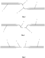
- the reinforcing elements (1) consist of, successively, a first end section (2), a central section (3) and a second end section (4). At the first and the second end sections (2, 4), the bundle of fibres is flattened, so that these comprise straight surfaces or curved surfaces. At the position of the central section (3), the bundle of fibres is twisted in such a way that the central section (3) extends in a longitudinal direction (A), has a circular cross section and comprises between 10 and 50 twists per m.
- the fibres extend next to each other and are hardly twisted, if at all.
- the end sections (2, 4) are flattened in such a way that they curve with respect to the longitudinal direction (A).
- the end sections (2, 4) extend along a plane which extends in said longitudinal direction (A) of the central section (3).
- the end sections (2, 4) are flattened and deflected from the central section (3) in such a way that they comprise three successive parts, respectively a first part which curves with respect to the longitudinal direction (A), a second part which extends virtually parallel to the longitudinal direction (A) and a third part which is deflected from the second part.
- the reinforcing elements (1) illustrated in Figs. 1 and 2 and the reinforcing elements (1) illustrated in Fig. 6 preferably form part of an assembly of reinforcing elements (1), wherein this assembly comprises virtually 50% of reinforcing elements (1) of the first embodiment or the fifth embodiment and comprises virtually 50% of reinforcing elements (1) of the second embodiment or the sixth embodiment.
- the central section (3) is twisted in a clockwise direction, viewed from the first end section (2) towards the second end section (4), and in the second and the sixth embodiment, the central section (3) is twisted in a counterclockwise direction, viewed from the first end section (2) towards the second end section (4).
Landscapes
- Engineering & Computer Science (AREA)
- Architecture (AREA)
- Civil Engineering (AREA)
- Structural Engineering (AREA)
- Reinforcement Elements For Buildings (AREA)
- Reinforced Plastic Materials (AREA)
- Working Measures On Existing Buildindgs (AREA)
- Bridges Or Land Bridges (AREA)
Claims (17)
- Verstärkungselement (1) für Beton, wobei dieses Verstärkungselement (1) ein Bündel aus harzimprägnierten Fasern umfasst, wobei das Verstärkungselement (1) nacheinander einen ersten Endabschnitt (2), einen Mittelabschnitt (3) und einen zweiten Endabschnitt (4) umfasst, wobei das Bündel der Fasern im Mittelabschnitt (3) verdrillt ist, dadurch gekennzeichnet, dass das Harz ein wasserabsorbierendes Harz ist, das in der Lage ist, mindestens das 1-fache seines Volumens in Wasser zu absorbieren, und zugelassen wird, dass das Harz erweicht und die Fasern verformt werden, wenn das Verstärkungselement (1) mit Beton im flüssigen Zustand gemischt wird, um Vorspannung in gehärtetem Beton zu erzeugen.
- Verstärkungselement (1) nach Anspruch 1, dadurch gekennzeichnet, dass die Fasern mit zwischen 10 und 50 Verdrillungen pro m in dem Mittelabschnitt (3) verdrillt sind.
- Verstärkungselement (1) nach einem der vorhergehenden Ansprüche, dadurch gekennzeichnet, dass das Bündel der Fasern an der Position von mindestens einem derartigen Endabschnitt (2, 4) abgeflacht ist.
- Verstärkungselement (1) nach Anspruch 3, dadurch gekennzeichnet, dass die Fasern an der Position des mindestens einen derartigen abgeflachten Endabschnitts größtenteils in einer nicht-verdrillten Position sind.
- Verstärkungselement (1) nach Anspruch 4, dadurch gekennzeichnet, dass die Fasern sich größtenteils nacheinander nebeneinander in derselben geraden oder gekrümmten Ebene an der Position des mindestens einen derartigen abgeflachten Endabschnitts (2, 4) erstrecken .
- Verstärkungselement (1) nach einem der Ansprüche 3 oder 5, dadurch gekennzeichnet, dass der Mittelabschnitt (3) sich in einer Längsrichtung (A) erstreckt und der abgeflachte Endabschnitt (2, 4) in Bezug zu der Längsrichtung (A) abgelenkt ist oder einen Winkel mit der Längsrichtung (A) bildet.
- Verstärkungselement (1) nach einem der vorhergehenden Ansprüche, dadurch gekennzeichnet, dass das Gewicht des Harzes 10 bis 30 Prozent des Gesamtgewichts des Verstärkungselements (1) stellt.
- Verstärkungselement (1) nach einem der vorhergehenden Ansprüche, dadurch gekennzeichnet, dass die Fasern Glasfasern sind.
- Verstärkungselement (1) nach einem der vorhergehenden Ansprüche, dadurch gekennzeichnet, dass das Harz ein Epoxyharz, ein Polyurethanharz oder ein Polyesterharz umfasst.
- Anordnung von Verstärkungselementen (1) für Beton, wobei diese Anordnung Verstärkungselemente (1) gemäß einem oder mehreren der Ansprüche 1 bis 9 umfasst.
- Anordnung nach Anspruch 10, dadurch gekennzeichnet, dass die Verstärkungselemente (1) nach einem oder mehreren der Ansprüche 1 bis 9 eine erste Gruppe von Verstärkungselementen (1), worin der Mittelabschnitt (3) dieser ersten Gruppe von Verstärkungselementen (1) im Uhrzeigersinn verdrillt ist, und eine zweite Gruppe von Verstärkungselementen (1) umfassen, worin der Mittelabschnitt (3) dieser zweiten Gruppe von Verstärkungselementen (1) gegen den Uhrzeigersinn verdrillt ist.
- Anordnung nach Anspruch 11, dadurch gekennzeichnet, dass die erste Gruppe der Verstärkungselemente (1) 10 bis 90 % aller Verstärkungselemente (1) stellt.
- Anordnung nach Anspruch 11 oder 12, dadurch gekennzeichnet, dass die zweite Gruppe der Verstärkungselemente (1) 10 bis 90 % aller Verstärkungselemente (1) stellt.
- Anordnung nach einem oder mehreren der Ansprüche 10 bis 13, dadurch gekennzeichnet, dass die Verstärkungselemente (1) nur Verstärkungselemente (1) gemäß einem oder mehreren der Ansprüche 1 bis 9 umfassen.
- Beton, der Verstärkungselemente (1) umfasst, dadurch gekennzeichnet, dass die Verstärkungselemente (1) Verstärkungselemente (1) gemäß einem oder mehreren der Ansprüche 1 bis 9 umfassen.
- Verfahren zur Fertigung einer Betonkonstruktion, wobei Beton produziert und Verstärkungselemente (1) in diesen Beton eingemischt werden, während der produzierte Beton noch in seinem flüssigen Zustand vorliegt, um eine flüssige Mischung zu produzieren, wobei diese flüssige Mischung in die gewünschte Form gegossen wird und diese Mischung abbinden gelassen wird, um die Betonkonstruktion zu bilden, dadurch gekennzeichnet, dass die Verstärkungselemente (1) Verstärkungselemente (1) gemäß einem oder mehreren der Ansprüche 1 bis 9 umfassen.
- Verfahren zur Fertigung einer Betonkonstruktion nach Anspruch 16, dadurch gekennzeichnet, dass das wasserabsorbierende Harz Wasser absorbiert, wenn sich der Beton noch in einem flüssigen Zustand befindet, und die Bündel der Fasern der Verstärkungselemente (1) somit an der Position des Mittelabschnitts (3) geringfügig entdrillt werden und länger werden, und wobei während des Abbindens des Betons das absorbierte Wasser das Harz verlässt und die Bündel der Fasern in ihre ursprüngliche Form zurückkehren, um so eine Betonkonstruktion zu bilden, die vorgespannten Beton umfasst.
Applications Claiming Priority (1)
| Application Number | Priority Date | Filing Date | Title |
|---|---|---|---|
| BE20195907A BE1027867B1 (nl) | 2019-12-16 | 2019-12-16 | Verstevigingselement voor beton |
Publications (3)
| Publication Number | Publication Date |
|---|---|
| EP3889369A1 EP3889369A1 (de) | 2021-10-06 |
| EP3889369B1 true EP3889369B1 (de) | 2024-11-27 |
| EP3889369C0 EP3889369C0 (de) | 2024-11-27 |
Family
ID=69147369
Family Applications (1)
| Application Number | Title | Priority Date | Filing Date |
|---|---|---|---|
| EP20213285.8A Active EP3889369B1 (de) | 2019-12-16 | 2020-12-11 | Verstärkungselement für beton |
Country Status (2)
| Country | Link |
|---|---|
| EP (1) | EP3889369B1 (de) |
| BE (1) | BE1027867B1 (de) |
Family Cites Families (5)
| Publication number | Priority date | Publication date | Assignee | Title |
|---|---|---|---|---|
| FR1366610A (fr) * | 1963-08-26 | 1964-07-10 | Metzeler Gummiwerke Ag | Béton renforcé |
| BE1009638A3 (nl) * | 1995-09-19 | 1997-06-03 | Bekaert Sa Nv | Staaldraadelement voor het mengen in achteraf verhardende materialen. |
| GB9700796D0 (en) * | 1997-01-16 | 1997-03-05 | Camplas Technology | Improvements relating to reinforcing bars |
| UA109284C2 (uk) * | 2010-10-21 | 2015-08-10 | Арматурний стрижень і спосіб його виробництва | |
| WO2017171668A1 (en) * | 2016-03-29 | 2017-10-05 | Kordsa Teknik Tekstil Anonim Sirketi | Macro synthetic concrete reinforcement material and production method thereof |
-
2019
- 2019-12-16 BE BE20195907A patent/BE1027867B1/nl active IP Right Grant
-
2020
- 2020-12-11 EP EP20213285.8A patent/EP3889369B1/de active Active
Also Published As
| Publication number | Publication date |
|---|---|
| BE1027867B1 (nl) | 2021-07-15 |
| EP3889369A1 (de) | 2021-10-06 |
| EP3889369C0 (de) | 2024-11-27 |
| BE1027867A1 (nl) | 2021-07-09 |
Similar Documents
| Publication | Publication Date | Title |
|---|---|---|
| US5727357A (en) | Composite reinforcement | |
| US20080141614A1 (en) | Flexible fiber reinforced composite rebar | |
| JPS61274036A (ja) | 構造用ロツドと強化構造部材 | |
| HRP20241126T1 (hr) | Armaturna šipka i postupak njezine proizvodnje | |
| ES2984144T3 (es) | Barra de refuerzo de FRP y método para fabricar la misma | |
| US6048598A (en) | Composite reinforcing member | |
| EP3256309B1 (de) | Vorgespanntes faserverstärkungselement und verfahren zu dessen herstellung | |
| US20160025173A1 (en) | Hybrid spring device | |
| TWI828788B (zh) | 複合筋 | |
| KR102060285B1 (ko) | 콘크리트 보강용 frp메쉬의 제조방법 | |
| EP0892876A1 (de) | Bewehrungsstäbe | |
| JPH0132058B2 (de) | ||
| EP3889369A1 (de) | Verstärkungselement für beton | |
| DE102016111176A1 (de) | Betonbewehrungsgitterelement, Verfahren zu dessen Herstellung sowie dessen Verwendung | |
| CN101611205A (zh) | 挠性纤维加强复合钢筋 | |
| RU2620699C2 (ru) | Стержень из непрерывных волокон | |
| JPH04224154A (ja) | コンクリート補強部材の製造法 | |
| JP6965404B1 (ja) | プレストレストコンクリートポール、その製造方法及びプレストレストコンクリートポール製造用定着装置 | |
| CA3116064C (en) | Composite rebar | |
| RU203161U1 (ru) | Композитный арматурный стержень на основе базальтового трощеного ровинга | |
| CZ17951U1 (cs) | Ovíjená výztuž z kompozitních materiálů | |
| RU159026U1 (ru) | Композитная арматура | |
| RU2521281C2 (ru) | Композитная арматура | |
| JPH0245741B2 (de) | ||
| KR101614850B1 (ko) | 다분할 조각 구조의 섬유보강폴리머 보강재 및 그 제작방법 |
Legal Events
| Date | Code | Title | Description |
|---|---|---|---|
| PUAI | Public reference made under article 153(3) epc to a published international application that has entered the european phase |
Free format text: ORIGINAL CODE: 0009012 |
|
| STAA | Information on the status of an ep patent application or granted ep patent |
Free format text: STATUS: THE APPLICATION HAS BEEN PUBLISHED |
|
| AK | Designated contracting states |
Kind code of ref document: A1 Designated state(s): AL AT BE BG CH CY CZ DE DK EE ES FI FR GB GR HR HU IE IS IT LI LT LU LV MC MK MT NL NO PL PT RO RS SE SI SK SM TR |
|
| STAA | Information on the status of an ep patent application or granted ep patent |
Free format text: STATUS: REQUEST FOR EXAMINATION WAS MADE |
|
| 17P | Request for examination filed |
Effective date: 20220406 |
|
| RBV | Designated contracting states (corrected) |
Designated state(s): AL AT BE BG CH CY CZ DE DK EE ES FI FR GB GR HR HU IE IS IT LI LT LU LV MC MK MT NL NO PL PT RO RS SE SI SK SM TR |
|
| STAA | Information on the status of an ep patent application or granted ep patent |
Free format text: STATUS: EXAMINATION IS IN PROGRESS |
|
| 17Q | First examination report despatched |
Effective date: 20231205 |
|
| GRAP | Despatch of communication of intention to grant a patent |
Free format text: ORIGINAL CODE: EPIDOSNIGR1 |
|
| STAA | Information on the status of an ep patent application or granted ep patent |
Free format text: STATUS: GRANT OF PATENT IS INTENDED |
|
| INTG | Intention to grant announced |
Effective date: 20240816 |
|
| GRAS | Grant fee paid |
Free format text: ORIGINAL CODE: EPIDOSNIGR3 |
|
| GRAA | (expected) grant |
Free format text: ORIGINAL CODE: 0009210 |
|
| STAA | Information on the status of an ep patent application or granted ep patent |
Free format text: STATUS: THE PATENT HAS BEEN GRANTED |
|
| AK | Designated contracting states |
Kind code of ref document: B1 Designated state(s): AL AT BE BG CH CY CZ DE DK EE ES FI FR GB GR HR HU IE IS IT LI LT LU LV MC MK MT NL NO PL PT RO RS SE SI SK SM TR |
|
| REG | Reference to a national code |
Ref country code: GB Ref legal event code: FG4D |
|
| REG | Reference to a national code |
Ref country code: CH Ref legal event code: EP |
|
| REG | Reference to a national code |
Ref country code: IE Ref legal event code: FG4D |
|
| REG | Reference to a national code |
Ref country code: DE Ref legal event code: R096 Ref document number: 602020041980 Country of ref document: DE |
|
| U01 | Request for unitary effect filed |
Effective date: 20241203 |
|
| U07 | Unitary effect registered |
Designated state(s): AT BE BG DE DK EE FI FR IT LT LU LV MT NL PT RO SE SI Effective date: 20241212 |
|
| U20 | Renewal fee for the european patent with unitary effect paid |
Year of fee payment: 5 Effective date: 20250221 |
|
| PG25 | Lapsed in a contracting state [announced via postgrant information from national office to epo] |
Ref country code: HR Free format text: LAPSE BECAUSE OF FAILURE TO SUBMIT A TRANSLATION OF THE DESCRIPTION OR TO PAY THE FEE WITHIN THE PRESCRIBED TIME-LIMIT Effective date: 20241127 Ref country code: IS Free format text: LAPSE BECAUSE OF FAILURE TO SUBMIT A TRANSLATION OF THE DESCRIPTION OR TO PAY THE FEE WITHIN THE PRESCRIBED TIME-LIMIT Effective date: 20250327 |
|
| PG25 | Lapsed in a contracting state [announced via postgrant information from national office to epo] |
Ref country code: ES Free format text: LAPSE BECAUSE OF FAILURE TO SUBMIT A TRANSLATION OF THE DESCRIPTION OR TO PAY THE FEE WITHIN THE PRESCRIBED TIME-LIMIT Effective date: 20241127 |
|
| PG25 | Lapsed in a contracting state [announced via postgrant information from national office to epo] |
Ref country code: NO Free format text: LAPSE BECAUSE OF FAILURE TO SUBMIT A TRANSLATION OF THE DESCRIPTION OR TO PAY THE FEE WITHIN THE PRESCRIBED TIME-LIMIT Effective date: 20250227 |
|
| PG25 | Lapsed in a contracting state [announced via postgrant information from national office to epo] |
Ref country code: GR Free format text: LAPSE BECAUSE OF FAILURE TO SUBMIT A TRANSLATION OF THE DESCRIPTION OR TO PAY THE FEE WITHIN THE PRESCRIBED TIME-LIMIT Effective date: 20250228 |
|
| PG25 | Lapsed in a contracting state [announced via postgrant information from national office to epo] |
Ref country code: PL Free format text: LAPSE BECAUSE OF FAILURE TO SUBMIT A TRANSLATION OF THE DESCRIPTION OR TO PAY THE FEE WITHIN THE PRESCRIBED TIME-LIMIT Effective date: 20241127 |
|
| PG25 | Lapsed in a contracting state [announced via postgrant information from national office to epo] |
Ref country code: RS Free format text: LAPSE BECAUSE OF FAILURE TO SUBMIT A TRANSLATION OF THE DESCRIPTION OR TO PAY THE FEE WITHIN THE PRESCRIBED TIME-LIMIT Effective date: 20250227 |
|
| PG25 | Lapsed in a contracting state [announced via postgrant information from national office to epo] |
Ref country code: SM Free format text: LAPSE BECAUSE OF FAILURE TO SUBMIT A TRANSLATION OF THE DESCRIPTION OR TO PAY THE FEE WITHIN THE PRESCRIBED TIME-LIMIT Effective date: 20241127 |
|
| PG25 | Lapsed in a contracting state [announced via postgrant information from national office to epo] |
Ref country code: SK Free format text: LAPSE BECAUSE OF FAILURE TO SUBMIT A TRANSLATION OF THE DESCRIPTION OR TO PAY THE FEE WITHIN THE PRESCRIBED TIME-LIMIT Effective date: 20241127 |
|
| PG25 | Lapsed in a contracting state [announced via postgrant information from national office to epo] |
Ref country code: CZ Free format text: LAPSE BECAUSE OF FAILURE TO SUBMIT A TRANSLATION OF THE DESCRIPTION OR TO PAY THE FEE WITHIN THE PRESCRIBED TIME-LIMIT Effective date: 20241127 |
|
| REG | Reference to a national code |
Ref country code: CH Ref legal event code: PL |
|
| PG25 | Lapsed in a contracting state [announced via postgrant information from national office to epo] |
Ref country code: MC Free format text: LAPSE BECAUSE OF FAILURE TO SUBMIT A TRANSLATION OF THE DESCRIPTION OR TO PAY THE FEE WITHIN THE PRESCRIBED TIME-LIMIT Effective date: 20241127 |
|
| PLBE | No opposition filed within time limit |
Free format text: ORIGINAL CODE: 0009261 |
|
| STAA | Information on the status of an ep patent application or granted ep patent |
Free format text: STATUS: NO OPPOSITION FILED WITHIN TIME LIMIT |
|
| PG25 | Lapsed in a contracting state [announced via postgrant information from national office to epo] |
Ref country code: CH Free format text: LAPSE BECAUSE OF NON-PAYMENT OF DUE FEES Effective date: 20241231 |
|
| PG25 | Lapsed in a contracting state [announced via postgrant information from national office to epo] |
Ref country code: IE Free format text: LAPSE BECAUSE OF NON-PAYMENT OF DUE FEES Effective date: 20241211 |
|
| GBPC | Gb: european patent ceased through non-payment of renewal fee |
Effective date: 20250227 |
|
| 26N | No opposition filed |
Effective date: 20250828 |
|
| PG25 | Lapsed in a contracting state [announced via postgrant information from national office to epo] |
Ref country code: GB Free format text: LAPSE BECAUSE OF NON-PAYMENT OF DUE FEES Effective date: 20250227 |
|
| U20 | Renewal fee for the european patent with unitary effect paid |
Year of fee payment: 6 Effective date: 20251230 |
|
| PG25 | Lapsed in a contracting state [announced via postgrant information from national office to epo] |
Ref country code: CY Free format text: LAPSE BECAUSE OF FAILURE TO SUBMIT A TRANSLATION OF THE DESCRIPTION OR TO PAY THE FEE WITHIN THE PRESCRIBED TIME-LIMIT Effective date: 20241127 |