EP3889352B1 - Method for producing a concrete block - Google Patents
Method for producing a concrete block Download PDFInfo
- Publication number
- EP3889352B1 EP3889352B1 EP21165991.7A EP21165991A EP3889352B1 EP 3889352 B1 EP3889352 B1 EP 3889352B1 EP 21165991 A EP21165991 A EP 21165991A EP 3889352 B1 EP3889352 B1 EP 3889352B1
- Authority
- EP
- European Patent Office
- Prior art keywords
- concrete
- concrete block
- layer
- block layer
- water
- Prior art date
- Legal status (The legal status is an assumption and is not a legal conclusion. Google has not performed a legal analysis and makes no representation as to the accuracy of the status listed.)
- Active
Links
- 239000004567 concrete Substances 0.000 title claims description 295
- 238000004519 manufacturing process Methods 0.000 title claims description 18
- XLYOFNOQVPJJNP-UHFFFAOYSA-N water Substances O XLYOFNOQVPJJNP-UHFFFAOYSA-N 0.000 claims description 45
- 239000000463 material Substances 0.000 claims description 33
- 238000009415 formwork Methods 0.000 claims description 32
- 238000000034 method Methods 0.000 claims description 20
- 239000004576 sand Substances 0.000 claims description 14
- 230000035699 permeability Effects 0.000 claims description 13
- GWEVSGVZZGPLCZ-UHFFFAOYSA-N Titan oxide Chemical compound O=[Ti]=O GWEVSGVZZGPLCZ-UHFFFAOYSA-N 0.000 claims description 7
- 239000011941 photocatalyst Substances 0.000 claims description 5
- 238000001035 drying Methods 0.000 claims description 3
- 239000004408 titanium dioxide Substances 0.000 claims description 3
- 230000000284 resting effect Effects 0.000 claims 1
- 238000001704 evaporation Methods 0.000 description 23
- 230000008020 evaporation Effects 0.000 description 22
- 239000004575 stone Substances 0.000 description 16
- 230000000694 effects Effects 0.000 description 9
- 238000001556 precipitation Methods 0.000 description 5
- 238000010521 absorption reaction Methods 0.000 description 4
- 239000000758 substrate Substances 0.000 description 4
- 239000002131 composite material Substances 0.000 description 3
- 238000011161 development Methods 0.000 description 3
- 230000018109 developmental process Effects 0.000 description 3
- 239000000203 mixture Substances 0.000 description 3
- MWUXSHHQAYIFBG-UHFFFAOYSA-N nitrogen oxide Inorganic materials O=[N] MWUXSHHQAYIFBG-UHFFFAOYSA-N 0.000 description 3
- 125000006850 spacer group Chemical group 0.000 description 3
- 238000003860 storage Methods 0.000 description 3
- 239000003570 air Substances 0.000 description 2
- 238000004887 air purification Methods 0.000 description 2
- 239000011449 brick Substances 0.000 description 2
- 239000003344 environmental pollutant Substances 0.000 description 2
- 238000001914 filtration Methods 0.000 description 2
- 230000008595 infiltration Effects 0.000 description 2
- 238000001764 infiltration Methods 0.000 description 2
- 239000008239 natural water Substances 0.000 description 2
- 230000001699 photocatalysis Effects 0.000 description 2
- 231100000719 pollutant Toxicity 0.000 description 2
- 230000005855 radiation Effects 0.000 description 2
- -1 steps Substances 0.000 description 2
- 238000010792 warming Methods 0.000 description 2
- 239000012080 ambient air Substances 0.000 description 1
- 239000011230 binding agent Substances 0.000 description 1
- 230000015572 biosynthetic process Effects 0.000 description 1
- 230000000903 blocking effect Effects 0.000 description 1
- 238000005056 compaction Methods 0.000 description 1
- 238000010276 construction Methods 0.000 description 1
- 238000001816 cooling Methods 0.000 description 1
- 230000003111 delayed effect Effects 0.000 description 1
- 239000007789 gas Substances 0.000 description 1
- 230000014509 gene expression Effects 0.000 description 1
- 239000003673 groundwater Substances 0.000 description 1
- 238000009776 industrial production Methods 0.000 description 1
- 239000007788 liquid Substances 0.000 description 1
- 238000012986 modification Methods 0.000 description 1
- 230000004048 modification Effects 0.000 description 1
- 239000002808 molecular sieve Substances 0.000 description 1
- 239000002105 nanoparticle Substances 0.000 description 1
- 210000001331 nose Anatomy 0.000 description 1
- 239000011148 porous material Substances 0.000 description 1
- 239000000843 powder Substances 0.000 description 1
- 238000002360 preparation method Methods 0.000 description 1
- 230000001105 regulatory effect Effects 0.000 description 1
- 230000035939 shock Effects 0.000 description 1
- URGAHOPLAPQHLN-UHFFFAOYSA-N sodium aluminosilicate Chemical compound [Na+].[Al+3].[O-][Si]([O-])=O.[O-][Si]([O-])=O URGAHOPLAPQHLN-UHFFFAOYSA-N 0.000 description 1
- 239000000126 substance Substances 0.000 description 1
Images


Classifications
-
- E—FIXED CONSTRUCTIONS
- E01—CONSTRUCTION OF ROADS, RAILWAYS, OR BRIDGES
- E01C—CONSTRUCTION OF, OR SURFACES FOR, ROADS, SPORTS GROUNDS, OR THE LIKE; MACHINES OR AUXILIARY TOOLS FOR CONSTRUCTION OR REPAIR
- E01C5/00—Pavings made of prefabricated single units
- E01C5/06—Pavings made of prefabricated single units made of units with cement or like binders
- E01C5/065—Pavings made of prefabricated single units made of units with cement or like binders characterised by their structure or component materials, e.g. concrete layers of different structure, special additives
-
- E—FIXED CONSTRUCTIONS
- E01—CONSTRUCTION OF ROADS, RAILWAYS, OR BRIDGES
- E01C—CONSTRUCTION OF, OR SURFACES FOR, ROADS, SPORTS GROUNDS, OR THE LIKE; MACHINES OR AUXILIARY TOOLS FOR CONSTRUCTION OR REPAIR
- E01C11/00—Details of pavings
- E01C11/22—Gutters; Kerbs ; Surface drainage of streets, roads or like traffic areas
- E01C11/224—Surface drainage of streets
- E01C11/225—Paving specially adapted for through-the-surfacing drainage, e.g. perforated, porous; Preformed paving elements comprising, or adapted to form, passageways for carrying off drainage
Definitions
- the invention relates to a method for producing a concrete block according to the preamble of patent claim 1.
- Concrete stones in particular paving stones, steps, bricks and boundary stones made of concrete are well known from the prior art. Such concrete blocks are often used in road, traffic route and landscaping construction for the production of surface coverings, walls, stairs or other structures permanently built into the ground.
- large areas of the surface are often designed as traffic areas that can be walked on or driven on, such as streets, paths, squares or parking lots, and are covered with surface coverings formed from concrete blocks of this type, in particular paving stones or slabs.
- the concrete blocks or paving stones made of concrete are preferably laid in combination on a bedding layer of the subsoil, specifically in such a way that joints are created between adjacent paving stones or shaped stones.
- the joints are filled with suitable, mostly sand-like joint materials.
- Such surface coverings in the form of patches are sufficiently known from the prior art.
- a surface covering made of two-layer shaped blocks is already known, which has a water-absorbing, water-permeable layer on the surface underneath an essentially water-impermeable layer. Due to the water-permeable design of the lower layer, the rainwater can flow down both over the joints and at least partially over the water-permeable layer in the direction of the bedding layer and thus almost completely hits the bedding layer, which means that so-called blocking of the joints can be reduced.
- the future goal is to preserve the natural water balance in settlement areas in order to limit damage caused by heavy rain.
- the rainwater should therefore evaporate and perspire and the rest seep away into the ground, i.e. be returned to the groundwater.
- the concrete block also has a multi-layer structure and is designed to be placed on a bedding layer of a substrate and to be laid in the composite.
- the molded block comprises at least one water-impermeable, first layer arranged along the upper side of the molded block and at least one immediately adjoining water-permeable, second layer and at least one third layer adjoining the second layer.
- the third layer is designed as a water-impermeable layer and is arranged on the underside of the concrete block intended to rest on the bedding layer, and the second layer arranged between the first and third layers is designed to absorb and store water.
- the impermeability of the third layer means that in the second layer Waterlogging forms and the second layer can become oversaturated.
- the disadvantage of this is that the onset of the evaporation effect is delayed or only occurs to a limited extent if the concrete block is heated too little.
- a further disadvantage is that the evaporation properties of such a concrete block are therefore limited due to the water-impermeable third layer.
- the formation of waterlogging during a freeze/thaw cycle can also lead to damage to the concrete block, which is particularly disadvantageous.
- Concrete stones within the meaning of the invention can in particular be paving stones and slabs made of concrete, which can be laid in combination on a bedding layer.
- the first step is to manufacture
- fine gravel and/or sand-rich concrete is introduced into the formwork, then in a second step for the production of the water-permeable second concrete block layer the no
- a water-permeable layer with a lower water permeability is understood in the sense of the invention as a concrete block layer in which water can penetrate through this layer, but with a time delay and/or compared to one water-permeable concrete block layer with normal or higher water permeability with a reduced or reduced speed.
- This layer is also not designed to absorb and store water. This particularly advantageously avoids waterlogging in the second concrete block layer, ie the amount of water absorbed by the second water-permeable concrete block layer can be adjusted or better regulated in such a way that improved evaporation properties of the concrete block or concrete paving block arise. This also effectively prevents damage to the concrete block in the event of waterlogging and a freeze/thaw cycle.
- the formwork or mold is removed and the compacted concrete material is then preferably cured in a drying chamber, the compacted concrete material already having the shape and dimensions of the concrete block or concrete paving stone after the formwork has been removed.
- the production according to the invention of the second layer of concrete blocks from an aggregate core concrete enables optimal absorption and storage of water in the concrete blocks.
- the fine concrete rich in chippings and/or sand and the no-fines core concrete introduced into the formwork are pre-compacted in an intermediate step before the facing concrete is introduced.
- coarse-grain crushed stone material can also be added to the fine gravel and/or sand-rich concrete.
- a fine grit and/or sand-rich concrete material with possibly a coarser-grained grit portion for the production of the third concrete block layer By using a fine grit and/or sand-rich concrete material with possibly a coarser-grained grit portion for the production of the third concrete block layer, a low level of water permeability is achieved, with the degree of this being determined by the respective mixture can be adjusted at least in part by the proportion of sand and/or chippings added and/or the grain size used in each case.
- small pores and/or cavities which produce a capillary effect, are formed in the concrete material mentioned and a correspondingly selected binder content in the third layer of concrete blocks. Because of this capillary effect, moisture that is still present in the bedding layer can be supplied to the second concrete block layer, for example via the third concrete block layer, as a result of which the evaporation properties of the concrete
- the first layer of concrete blocks is produced from partially water-permeable or water-impermeable facing concrete.
- precipitation water can also be fed via the first concrete block layer to the second, water-storing concrete block layer or escape again in the event of evaporation.
- the water-impermeable design of the facing concrete layer enables the targeted supply of rainwater via the joints or the joint material located therein, so that effective filtering of the rainwater via this infiltration path is particularly advantageous.
- the third concrete block layer can also advantageously be produced with a layer thickness of between 3% and 15% of the total height of the concrete block body, preferably between 3% and 8% of the total height of the concrete block body.
- the third layer of concrete blocks can be produced with a layer thickness between 3 mm and 10 mm, preferably between 3 mm and 8 mm.
- the second concrete block layer is produced with a layer thickness between 60% and 90% of the total height of the concrete block body, preferably between 70% and 85% of the total height of the concrete block body.
- the second concrete block layer thus forms a large part of the concrete block body, so that a large amount of water can be stored in it and released again.
- the concrete block is advantageously produced in one piece or in one piece, i.e. all three concrete block layers are produced in one production process in the form of a complete block.
- the third layer of concrete blocks is produced with a water permeability which is reduced by at least 30%, preferably by 50%, compared to the water permeability of the second layer of concrete blocks. This ensures sufficient saturation of the second layer of concrete blocks with rainwater guaranteed, but effectively prevents oversaturation. This significantly improves the evaporation properties of the concrete block.
- a photocatalyst such as titanium dioxide is incorporated into the first concrete block layer.
- the surface of the concrete block is thus designed for photocatalytic air purification. Irradiation with light, preferably sunlight, can particularly advantageously oxidize harmful gases present in the ambient air, such as nitrogen oxides or volatile organic substances, and thus remove them from the air.
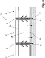
- FIG 1 is an example of a perspective view of a concrete block 1 produced according to the method according to the invention and FIG figure 2 a schematic section along a sectional plane running parallel to the central longitudinal axis MLA and the longitudinal axis LA of the concrete block 1 is shown.
- the concrete block 1 is preferably designed in the form of a surface element that can be laid in combination to create a surface covering.
- concrete block or concrete slab are understood to be essentially structurally identical elements that can be used in a manner known per se to create a surface covering. Depending on the selected laying pattern, these are interlocked with one another and laid flush with one another, so that a preferably level surface covering 10 is produced.
- a concrete block 1 produced according to the method according to the invention comprises at least one multi-layered concrete block body 2 with at least one level concrete block underside 2.1 and an essentially flat concrete block upper side 2.2 opposite this, which preferably forms the tread surface or trafficable surface or traffic surface.
- the specific design of the lateral surface sections of the concrete block 1 is not relevant to the invention, i.e. the specific cross-sectional shape of the concrete block 1 can be chosen almost arbitrarily without departing from the idea of the invention.
- the concrete block 1 is cuboid and has two concrete block sides 2.3, 2.4 that are opposite one another and have the same surface area.
- the underside of the concrete block 2.1 and the upper side of the concrete block 2.2 run perpendicular or approximately perpendicular to the central longitudinal axis MLA of the concrete block body 2 or concrete block 1, with the concrete block sides 2.4 being oriented perpendicularly and the concrete block sides 2.3 parallel to the longitudinal axis LA of the concrete block body 2 or concrete block 1.
- the multi-layer concrete block body 2 comprises at least one first concrete block layer 2a forming the concrete block upper side 2.2, at least one water-permeable second concrete block layer 2b adjoining the first concrete block layer 2a and a third concrete block layer 2c immediately adjoining the second concrete block layer 2b, with the third concrete block layer 2c forming the concrete block underside 2.1 forms, which is intended to rest on a bedding layer 3 of a substrate, and wherein between the first and third concrete block layer 2a, 2c arranged second concrete block layer 2b is designed for receiving and storing water.
- the third concrete block layer 2c is made water-permeable according to the invention, with the third concrete block layer 2c having a lower water permeability in comparison to the second concrete block layer 2 .
- a water-permeable layer with low water permeability is understood in the present context to mean a concrete block layer through which water can be transported or passed, but with a time delay and/or with a reduced flow rate compared to the second, water-permeable concrete block layer 2b.
- the method according to the invention for producing or manufacturing the concrete block 1 with improved evaporation properties can be carried out by means of industrial production methods in which concrete blocks are produced in a process-controlled manner, preferably in layers, i.e. several concrete blocks at the same time in one layer.
- a concrete formwork known per se is first provided for the production of concrete blocks 1, in particular in the form of paving blocks or slabs.
- first step to produce the at least partially water-permeable third concrete block layer 2c fine gravel and/or sand-rich concrete is introduced into the formwork or mold and, in a second step, to produce the water-permeable second concrete block layer 2b, additional no-fines Core concrete introduced into the formwork or form.
- second step to produce the water-permeable second concrete block layer 2b, additional no-fines Core concrete introduced into the formwork or form.
- facing concrete is introduced into the formwork or mold, with the concrete material introduced being subsequently compacted.
- the formwork or mold is removed, with the compacted concrete block 1 remaining on a support and holding plate.
- the hardening of the compacted concrete block 1 preferably takes place in a drying chamber.
- the fine chippings and/or sand-rich concrete and the no-fines core concrete introduced into the formwork are pre-compacted in an intermediate step before the facing concrete is introduced.
- the fine grit and/or sand-rich concrete can be introduced into the formwork over a thin surface using a first concrete spreader and then the no-fines core concrete can be thickly introduced into the formwork using a second concrete spreader, and the concrete layers introduced using a stamp and/or shaking vibration of the support and holding plate in the formwork or mold are pre-compacted.
- Lowering the stamp onto the formwork or form introduced concrete material and the subsequent exposure to a vibrating impact on the part of the support and holding plate is also referred to as "intermediate sinking".
- the third concrete block layer 2c is preferably made from a fine concrete material rich in chippings and/or sand, which has at least moderate water permeability. If necessary, a coarse-grained grit portion can be added.
- the concrete block 1 or the concrete block body 2 is produced with an overall height H, which preferably corresponds to the sum of the layer thicknesses Da, Db, Dc of the first to third concrete block layers 2a, 2b, 2c.
- the first concrete block layer 2a has a first layer thickness Da
- the second concrete block layer 2b has a second layer thickness Db
- the third concrete block layer 2c has a third layer thickness Dc.
- the third layer thickness Dc of the third concrete block layer 2c is between 3 mm and 15 mm, preferably between 3 mm and 8 mm. Based on the total layer thickness H of the concrete block, the third layer thickness Dc is between 3% and 15% of the total height H of the concrete block body 2, preferably between 3% and 10% of the total height H of the concrete block body 2.
- the second layer thickness Db of the second concrete block layer 2b is between 60% and 90% of the total height H of the concrete block body 2, preferably between 70% and 85% of the total height H of the concrete block body 2.
- the second layer thickness Db of the second concrete block layer 2b is, for example, in the present exemplary embodiment approximately 80% of the total height H of the shaped block 1.
- the first layer thickness Da is 1.5 cm, for example, and the second layer thickness Db is 8, for example cm and the third layer thickness Dc is, for example, 0.5 cm.
- the first, the concrete block top 2.2 forming concrete block layer 2a is made of a water-permeable or water-impermeable facing concrete, as water-impermeable facing concrete, a structurally dense, impermeable concrete material is used.
- the first concrete block layer 2a is preferably directly followed by the second concrete block layer 2b, which is made of no-fines core concrete with a large proportion of fine and micropores. This no-fines concrete layer 2b supports the absorption and storage of water and thus enables water to penetrate through the concrete block sides 2.3, 2.4 into the second concrete block layer 2b.
- the water temporarily stored in the second layer of concrete block 2b can be released to the outside again, in vapor form again via the concrete block sides 2.3, 2.4 and/or, if the first layer of concrete block 2a is permeable to water, via these escape from the concrete block 1 or be released into the environment.
- the concrete block 1 has so-called spacers or spacer noses 4, which ensure uniform joints 5 of approximately equal width when the concrete block 1 is laid in the composite and ensure a minimum width of the joints 5.
- FIG 3 a section through a surface covering 10 formed by means of concrete blocks 1 designed according to the invention is shown as an example.
- the surface covering 10 comprises a multiplicity of multi-layered concrete blocks 1 laid on a bedding layer 3 of a subsoil.
- the concrete blocks 1 used to produce the surface covering 10 are designed in three layers according to the invention and each have a first, a second and a third concrete block layer 2a, 2b, 2c up.
- Joints 5 are formed between adjacent concrete blocks 1 of the surface covering 10 , which are filled with a joint material 6 and form a seepage path for draining rainwater from the surface of the surface covering 10 facing away from the bedding layer 3 .
- the bedding layer 3 is a conventional bedding layer, which essentially consists of a material mixture with a grain size of 0.1 mm to 5 mm. After the concrete blocks 1 have been laid in the composite, the joint material 6 is swept dry into the joints 5 . Following this, the surface covering 10 is shaken off and, if necessary, grouted again, ie additional joint material 6 is filled into joints 6 that are not yet completely filled. This process can be repeated again after a certain time.
- the joint material 7 of the present exemplary embodiment consists, for example, of a mixture of a proportion of sand, a proportion of fines and an artificial molecular sieve, and thus forms a filter layer for removing pollutants from the rainwater.
- conventional joint material can also be used if no pollutant filtering is desired.
- FIG. 4 To illustrate the water cycle taking place on the surface covering 10 is in the figures 4 and 5 a section of the surface covering 10 is shown in a sectional view, with figure 4 the seepage and absorption route for rainwater and in figure 5 the evaporation path for precipitation water temporarily stored in the concrete block 1 and there in particular in the second concrete block layer 2b is indicated.
- Precipitation water impinges on the surface of the surface covering 10 on the first concrete block layer 2a of the concrete blocks 1 and preferably seeps through the joints 5 into the joint material 6, with the rainwater also being conducted away from the first concrete block layer 2a if it is at least partially water-permeable. Irrespective of this, at least part of the precipitation water that is moving in the direction of the bedding layer 4 and seeps away from the joint material 6 gets into the second concrete block layer 2b, which preferably absorbs the water like a sponge.
- the supply takes place via the concrete stone sides 2.3, 2.4 bordering on the joint material 7.
- the seepage and transport route of the rainwater is shown in figure 4 indicated by black arrows.
- part of the precipitation water absorbed in the second concrete block layer 2b can also be discharged into the bedding layer 3 or the subsoil, so that optimal water flow is achieved. In particular, this avoids oversaturation of the second concrete block layer 2b with rainwater, which would impair the evaporation properties.
- the rainwater temporarily stored in the second concrete block layer 2b of the concrete blocks 1 can therefore evaporate significantly better than in the case of concrete blocks 3 known from the prior art, which have a water-impermeable provide a third layer of concrete blocks.
- the evaporating water reaches the surface in the form of water vapor from the second concrete block layer 2b of the concrete block 1 either via the joint material 6 and/or the water-permeable first concrete block layer 2a, where it is released into the air above.
- a possible evaporation path of the water is in figure 5 indicated by double arrows.
- the sheet material 10 is particularly suitable for an effective contribution to a to provide environmentally friendly drainage planning, in particular to achieve an evapotranspiration of between 34% and 92% of the rainwater.
- moisture can be supplied from the bedding layer 3 or the subsoil into the second concrete block layer 2b, thereby additionally improving the evaporation properties of the concrete block 1, in particular increasing the evaporation rate.
- the first concrete block layer 2a forming the top side 2.2 of the concrete block can be produced in one embodiment from a concrete material with incorporated photocatalysts such as, for example, titanium dioxide.
- a concrete material with incorporated photocatalysts such as, for example, titanium dioxide.
- nanoparticles of titanium dioxide (TiO2) preferably in powder form or in liquid form, are added to the concrete material provided for the production of the first concrete block layer 2a.
- the first concrete block layer 2a with incorporated photocatalysts serves as a photocatalyst, via which photocatalytic air purification takes place under solar radiation.
Description
Die Erfindung betrifft ein Verfahren zur Herstellung eines Betonsteins gemäß dem Oberbegriff des Patentanspruches 1.The invention relates to a method for producing a concrete block according to the preamble of
Betonsteine, insbesondere Pflastersteine, Treppenstufen, Mauer- und Begrenzungssteine aus Beton sind hinlänglich aus dem Stand der Technik bekannt. Derartige Betonsteine werden häufig im Straßen-, Verkehrswege- und Landschaftsbau zur Herstellung von Flächenbelägen, Mauern, Treppen oder sonstigen fest mit dem Boden verbauten Bauwerken eingesetzt.Concrete stones, in particular paving stones, steps, bricks and boundary stones made of concrete are well known from the prior art. Such concrete blocks are often used in road, traffic route and landscaping construction for the production of surface coverings, walls, stairs or other structures permanently built into the ground.
Beispielsweise in urbanen Gebieten sind häufig große Bereiche der Oberfläche als begehbare oder befahrbare Verkehrsflächen wie Straßen, Wege, Plätze oder Parkplätze ausgebildet und mit aus derartigen Betonsteinen, insbesondere Pflastersteinen oder -platten gebildeten Flächenbelägen bedeckt. Die Betonsteine bzw. Pflastersteine aus Beton werden vorzugsweise auf einer Bettungsschicht des Untergrundes im Verbund verlegt, und zwar derart, dass zwischen benachbarten Pflaster- bzw. Formsteinen Fugen entstehen. Die Fugen werden mit geeigneten, meist sandartigen Fugenmaterialien verfüllt. Solche, in Form von Pflastern ausgebildete Flächenbeläge sind aus dem Stand der Technik hinreichend bekannt.In urban areas, for example, large areas of the surface are often designed as traffic areas that can be walked on or driven on, such as streets, paths, squares or parking lots, and are covered with surface coverings formed from concrete blocks of this type, in particular paving stones or slabs. The concrete blocks or paving stones made of concrete are preferably laid in combination on a bedding layer of the subsoil, specifically in such a way that joints are created between adjacent paving stones or shaped stones. The joints are filled with suitable, mostly sand-like joint materials. Such surface coverings in the form of patches are sufficiently known from the prior art.
Bei allen mit einem Flächenbelag versehenen Flächen muss darauf geachtet werden, dass das auf die Oberfläche des Flächenbelags auftreffende Niederschlagswasser möglichst effektiv und ausreichend abgeführt wird. Bei den oberhalb genannten Pflastern aus Formsteinen erfolgt das Abführen des auftreffenden Niederschlagswassers in der Regel durch Versickern, wobei das Niederschlagswasser je nach Beschaffenheit der Formsteine, insbesondere je nach Art des zur Herstellung der Formsteine verwendeten Betons, lediglich über einen Versickerungsweg durch die Fugen oder aber über einen Versickerungsweg durch die Fugen und die Formsteine selbst versickern kann.For all surfaces provided with a surface covering, care must be taken to ensure that the rainwater that hits the surface of the surface covering is drained off as effectively and sufficiently as possible. In the case of the above-mentioned paving stones made of shaped stones, the rainwater that falls on it is usually drained off by seeping away, whereby the rainwater, depending on the nature of the shaped stones, in particular depending on the type of concrete used to produce the shaped stones, only flows via a seepage path through the joints or via a seepage path through the joints and the shaped bricks themselves.
Aus der
Auch gilt es bei großflächig angelegten und mit Flächenbelägen versehenen Verkehrsflächen aus städteplanerischer Sicht zu beachten, dass derartige Verkehrsflächen insbesondere in den Sommermonaten zu einem erheblichen Anteil zu einer überdurchschnittlichen innerstädtischen Erwärmung beitragen. Über die tagsüber auftreffende Sonneneinstrahlung werden die Flächenbeläge aufgeheizt, speichern diese Wärme und geben diese nachts als Wärmestrahlung wieder ab. Dieses Phänomen wird als "urbaner Hitzeinseleffekt" bezeichnet. Hierdurch kann in Stadtgebieten im Vergleich zu ländlichen Gebieten insbesondere nachts eine zusätzliche Erwärmung um mehrere Grad Celsius hervorgerufen werden. Um diesen urbanen "Hitzeinseleffekt" entgegenzuwirken, ist es bereits bekannt, eine gesteigerte Wasserverdunstung vorzusehen, da bekanntlich bei der Verdunstung von Wasser Verdunstungskälte entsteht. Daher ist es wünschenswert, eine erhöhte Verdunstungsrate auch über spezielle Flächenbeläge urbaner Verkehrsflächen zu erreichen.From an urban planning point of view, it is also important to note that large-scale traffic areas with surface coverings make a significant contribution to above-average inner-city warming, especially in the summer months. The surface coverings are heated up by the sunlight that hits them during the day, store this heat and give it off again at night as thermal radiation. This phenomenon is known as the "urban heat island effect". This can result in additional warming of several degrees Celsius in urban areas compared to rural areas, especially at night. In order to counteract this urban "heat island effect", it is already known to provide increased water evaporation, since it is known that the evaporation of water causes evaporation cold. It is therefore desirable to achieve an increased evaporation rate via special surface coverings of urban traffic areas.
Gemäß einem in Deutschland angedachten Entwässerungsplan ist zukünftiges Ziel der Erhalt des natürlichen Wasserhaushaltes in Siedlungsgebieten, um Schäden durch Starkregen einzugrenzen. Optimaler Weise sollen zwischen 34 % und 92 % des Niederschlagswassers demnach verdunsten und transpirieren und der Rest im Grund versickern, d.h. dem Grundwasser wieder zugeführt werden.According to a drainage plan being considered in Germany, the future goal is to preserve the natural water balance in settlement areas in order to limit damage caused by heavy rain. Optimally, between 34% and 92% of the rainwater should therefore evaporate and perspire and the rest seep away into the ground, i.e. be returned to the groundwater.
Daher besteht ein Bedarf an Flächenbelägen, die in der Lage sind, Wasser aufzunehmen und zu speichern und das zwischengespeicherte Wasser bei Wärmeeinwirkung über Verdunstung wieder an die Umgebung abzugeben.There is therefore a need for surface coverings that are able to absorb and store water and release the temporarily stored water back into the environment via evaporation when exposed to heat.
Derartige Flächenbeläge sind bereits aus der
Auch ist aus der
Ausgehend davon ist es Aufgabe der Erfindung, ein Verfahren zur Herstellung eines Betonsteins, insbesondere eines Pflastersteins aus Beton anzugeben, dass die Nachteile des Standes der Technik beseitigt und welches die Herstellung eines Betonsteins ermöglicht, der auch zur Aufnahme von Feuchtigkeit aus dem Bettungsmaterial unterhalb des Betonsteins ausgebildet ist. Die Aufgabe wird durch ein Verfahren zur Herstellung eines Betonsteins gemäß Patentanspruch 1 gelöst.Proceeding from this, it is the object of the invention to specify a method for producing a concrete block, in particular a concrete paving block, that eliminates the disadvantages of the prior art and which enables the production of a concrete block that also absorbs moisture from the bedding material underneath the concrete block is trained. The object is achieved by a method for producing a concrete block according to
Betonsteine im Sinne der Erfindung können insbesondere Pflastersteine und Platten aus Beton sein, welche im Verbund auf einer Bettungsschicht verlegbar sind.Concrete stones within the meaning of the invention can in particular be paving stones and slabs made of concrete, which can be laid in combination on a bedding layer.
Bei dem erfindungsgemäßen Verfahren zur Herstellung eines Betonsteins umfassend zumindest einen, mehrschichtig ausgebildeten Betonsteinkörper mit zumindest einer ebenen Betonsteinunterseite und einer dieser gegenüberliegenden im Wesentlichen flachen Betonsteinoberseite, wobei der Betonsteinkörper zumindest eine die Betonsteinoberseite bildende erste Betonschicht aus Vorsatzbeton, zumindest eine an die erste Betonsteinschicht anschließende, wasserdurchlässige zweite Betonsteinschicht aus haufwerksporigem Kernbeton sowie eine an die zweite Betonsteinschicht unmittelbar anschließende dritte Betonsteinschicht aufweist, wobei die dritte Betonsteinschicht die Betonsteinunterseite bildet, die zur Auflage auf einer Bettungsschicht eines Untergrundes vorgesehen ist, und wobei die zwischen der ersten und dritten Betonsteinschicht angeordnete zweite Betonsteinschicht zur Aufnahme und Speicherung von Wasser ausgebildet ist, wird nach Bereitstellung einer Schalung in einem ersten Schritt zur Herstellung der dritten Betonsteinschicht mit einer im Vergleich zur zweiten Betonsteinschicht geringeren Wasserdurchlässigkeit feiner splitt- und/oder sandreicher Beton in die Schalung eingebracht, anschließend wird in einem zweiten Schritt zur Herstellung der wasserdurchlässigen zweiten Betonsteinschicht zusätzlich der haufwerksporige Kernbeton in die Schalung eingebracht und in einem dritten Schritt wird zur Herstellung der ersten Betonsteinschicht der Vorsatzbeton in die Schalung eingebracht, wobei das eingebrachte Betonmaterial anschließend verdichtet wird. Unter der Herstellung einer wasserdurchlässigen Schicht mit einer geringeren Wasserdurchlässigkeit wird im erfindungsgemäßen Sinne eine Betonsteinschicht verstanden, bei der Wasser zwar durch diese Schicht hindurchdringen kann, jedoch zeitverzögert und/oder im Vergleich zu einer wasserdurchlässigen Betonsteinschicht mit normaler oder höherer Wasserdurchlässigkeit mit einer verminderten oder reduzierten Geschwindigkeit. Auch ist diese Schicht an sich nicht zur Aufnahme und Speicherung von Wasser ausgebildet. Besonders vorteilhaft wird dadurch das Entstehen von Staunässe in der zweiten Betonsteinschicht vermieden, d.h. die von der zweiten wasserdurchlässigen Betonsteinschicht aufgenommene Wassermenge ist dadurch einstellbar bzw. besser regulierbar, und zwar derart, dass verbesserte Verdunstungseigenschaften des Betonsteins bzw. Betonpflastersteins entstehen. Auch wird hierdurch effektiv eine Beschädigung des Betonsteins bei Auftreten von Staunässe und einem Frost-/Tauwechsel vermieden. Es ergibt sich aufgrund der wasserdurchlässigen Ausbildung der dritten Betonsteinschicht noch der weitere Vorteil, dass im Bettungsmaterial unterhalb des Betonsteins befindliche Feuchtigkeit bedingt durch den Kapillareffekt über die dritte Schicht in den Betonstein gesaugt werden kann. Hierdurch wird die Verdunstungsmenge aus dem Betonsteins in die Atmosphäre zusätzlich erhöht.In the method according to the invention for the production of a concrete block, comprising at least one multi-layered concrete block body with at least one level concrete block underside and an essentially flat concrete block upper side lying opposite it, the concrete block body having at least one first concrete layer of facing concrete forming the concrete block upper side, at least one adjoining the first concrete block layer, water-permeable second layer of concrete blocks made of no-fines core concrete and a third layer of concrete blocks directly adjoining the second layer of concrete blocks, the third layer of concrete blocks forming the underside of the concrete blocks, which is intended to be placed on a bedding layer of a substrate, and the second layer of concrete blocks arranged between the first and third layers of concrete blocks for absorbing and storing water, after providing a formwork, the first step is to manufacture In order to fill the third concrete block layer with a lower water permeability compared to the second concrete block layer, fine gravel and/or sand-rich concrete is introduced into the formwork, then in a second step for the production of the water-permeable second concrete block layer the no-fines core concrete is additionally introduced into the formwork and in a third step In the first step, the facing concrete is introduced into the formwork to produce the first layer of concrete blocks, with the concrete material being introduced then being compacted. The production of a water-permeable layer with a lower water permeability is understood in the sense of the invention as a concrete block layer in which water can penetrate through this layer, but with a time delay and/or compared to one water-permeable concrete block layer with normal or higher water permeability with a reduced or reduced speed. This layer is also not designed to absorb and store water. This particularly advantageously avoids waterlogging in the second concrete block layer, ie the amount of water absorbed by the second water-permeable concrete block layer can be adjusted or better regulated in such a way that improved evaporation properties of the concrete block or concrete paving block arise. This also effectively prevents damage to the concrete block in the event of waterlogging and a freeze/thaw cycle. Due to the water-permeable design of the third concrete block layer, there is the further advantage that moisture in the bedding material below the concrete block can be sucked into the concrete block via the third layer due to the capillary effect. This further increases the amount of evaporation from the concrete block into the atmosphere.
Nach dem Verdichten des eingebrachten Betonmaterials wird die Schalung bzw. Form entfernt und anschließend das verdichtete Betonmaterial vorzugsweise in einer Trockenkammer ausgehärtet, wobei das verdichtete Betonmaterial nach dem Entfernen der Schalung bereits die Form und Abmessungen des Betonsteins bzw. Pflastersteins aus Beton aufweist.After the concrete material has been compacted, the formwork or mold is removed and the compacted concrete material is then preferably cured in a drying chamber, the compacted concrete material already having the shape and dimensions of the concrete block or concrete paving stone after the formwork has been removed.
Durch die erfindungsgemäße Herstellung der zweiten Betonsteinschicht aus einem haufwerksporigen Kernbeton ist eine optimale Aufnahme und Speicherung von Wasser im Betonstein möglich.The production according to the invention of the second layer of concrete blocks from an aggregate core concrete enables optimal absorption and storage of water in the concrete blocks.
In einer bevorzugten Ausführungsvariante werden der in die Schalung eingebrachte feine splitt- und/oder sandreiche Beton und der haufwerksporige Kernbeton vor dem Einbringen des Vorsatzbetons in einem Zwischenschritt vorverdichtet.In a preferred embodiment variant, the fine concrete rich in chippings and/or sand and the no-fines core concrete introduced into the formwork are pre-compacted in an intermediate step before the facing concrete is introduced.
Weiterhin vorteilhaft werden der feine splitt- und/oder sandreiche Beton mit ersten Betonverteilermittel dünnflächig und anschließend der haufwerksporige Kernbeton mit einem zweiten Betonverteilermittler dickflächig darüber in die Schalung eingebracht sowie die eingebrachten beiden Betonschichten mittels eines Stempels und/oder Rüttelvibration in der Schalung vorverdichtet.It is also advantageous to place the fine chippings and/or sand-rich concrete thinly in the formwork with a first concrete distributor and then the no-fines core concrete with a second concrete distributor over it over a thick surface, and to precompact the two concrete layers that have been introduced in the formwork using a stamp and/or vibrating vibration.
Abhängig von der gewünschten Wasserdurchlässigkeit kann dem feinen splitt- und/oder sandreichen Beton auch noch grobkörnig zerkleinertes Steinmaterial zugesetzt werden. Durch die Verwendung eines feinen splitt- und/oder sandreichen Betonmaterials mit ggf. einem grobkörnigeren Splittanteil zur Herstellung der dritten Betonsteinschicht wird eine geringe Wasserdurchlässigkeit erreicht, wobei der Grad dessen durch die jeweilige Mischung zumindest teilweise durch den zugegebenen Anteil an Sand und/oder Splitt und/oder die jeweils verwendete Körnung einstellbar ist. Vorteilhaft entstehen bei dem genannten Betonmaterial und entsprechend gewählten Bindemittelgehalt in der dritten Betonsteinschicht kleine Poren und/oder Hohlräume, die eine Kapillarwirkung erzeugen. Aufgrund dieser Kapillarwirkung kann beispielsweise über die dritte Betonsteinschicht auch noch in der Bettungsschicht vorhandene Feuchtigkeit der zweiten Betonsteinschicht zugeführt werden, wodurch die Verdunstungseigenschaften des Betonsteins noch weiter verbessert werden können.Depending on the desired water permeability, coarse-grain crushed stone material can also be added to the fine gravel and/or sand-rich concrete. By using a fine grit and/or sand-rich concrete material with possibly a coarser-grained grit portion for the production of the third concrete block layer, a low level of water permeability is achieved, with the degree of this being determined by the respective mixture can be adjusted at least in part by the proportion of sand and/or chippings added and/or the grain size used in each case. Advantageously, small pores and/or cavities, which produce a capillary effect, are formed in the concrete material mentioned and a correspondingly selected binder content in the third layer of concrete blocks. Because of this capillary effect, moisture that is still present in the bedding layer can be supplied to the second concrete block layer, for example via the third concrete block layer, as a result of which the evaporation properties of the concrete block can be improved even further.
In einer Weiterbildung der Erfindung wird die erste Betonsteinschicht aus teilweise wasserdurchlässigen oder wasserundurchlässigen Vorsatzbeton hergestellt. Durch die Herstellung einer wasserdurchlässigen Vorsatzbetonschicht kann auch über die erste Betonsteinschicht der zweiten, wasserspeichernden Betonsteinschicht Niederschlagswasser zugeführt werden oder auch im Verdunstungsfall wieder entweichen. Die wasserundurchlässige Ausgestaltung der Vorsatzbetonschicht ermöglicht die gezielte Zuführung des Niederschlagswassers über die Fugen bzw. das darin befindliche Fugenmaterial, so dass besonders vorteilhaft auch noch eine effektive Filterung des Niederschlagswassers über diesen Versickerungsweg möglich ist.In a further development of the invention, the first layer of concrete blocks is produced from partially water-permeable or water-impermeable facing concrete. By producing a water-permeable facing concrete layer, precipitation water can also be fed via the first concrete block layer to the second, water-storing concrete block layer or escape again in the event of evaporation. The water-impermeable design of the facing concrete layer enables the targeted supply of rainwater via the joints or the joint material located therein, so that effective filtering of the rainwater via this infiltration path is particularly advantageous.
Weiterhin vorteilhaft kann die dritte Betonsteinschicht mit einer Schichtdicke zwischen 3% und 15% der Gesamthöhe des Betonsteinkörpers, bevorzugt zwischen 3% und 8% der Gesamthöhe des Betonsteinkörpers hergestellt werden. Insbesondere kann die dritte Betonsteinschicht mit einer Schichtdicke zwischen 3 mm und 10 mm, vorzugsweise zwischen 3 mm und 8 mm hergestellt werden.The third concrete block layer can also advantageously be produced with a layer thickness of between 3% and 15% of the total height of the concrete block body, preferably between 3% and 8% of the total height of the concrete block body. In particular, the third layer of concrete blocks can be produced with a layer thickness between 3 mm and 10 mm, preferably between 3 mm and 8 mm.
In einer bevorzugten Ausführungsvariante wird die zweite Betonsteinschicht mit einer Schichtdicke zwischen 60% und 90% der Gesamthöhe des Betonsteinkörpers, bevorzugt zwischen 70% und 85% der Gesamthöhe des Betonsteinkörpers hergestellt. Die zweite Betonsteinschicht bildet damit einen Großteil des Betonsteinkörpers aus, so dass eine hohe Wassermenge darin speicherbar und wieder abgebbar ist.In a preferred embodiment variant, the second concrete block layer is produced with a layer thickness between 60% and 90% of the total height of the concrete block body, preferably between 70% and 85% of the total height of the concrete block body. The second concrete block layer thus forms a large part of the concrete block body, so that a large amount of water can be stored in it and released again.
Vorteilhaft wird der Betonstein einstückig oder einteilig hergestellt, d.h. alle drei Betonsteinschichten werden in einem Herstellungsverfahren in Form eines Gesamtsteins hergestellt.The concrete block is advantageously produced in one piece or in one piece, i.e. all three concrete block layers are produced in one production process in the form of a complete block.
In einer Weiterbildung der Erfindung wird die dritte Betonsteinschicht mit einer Wasserdurchlässigkeit hergestellt, die im Vergleich zur Wasserdurchlässigkeit der zweiten Betonsteinschicht um wenigstens 30%, vorzugsweise um 50% reduziert ist. Hierdurch wird eine ausreichende Sättigung der zweiten Betonsteinschicht mit Niederschlagswasser gewährleistet, jedoch eine Übersättigung dessen effektiv verhindert. Die Verdunstungseigenschaften des Betonsteins werden damit deutlich verbessert.In a development of the invention, the third layer of concrete blocks is produced with a water permeability which is reduced by at least 30%, preferably by 50%, compared to the water permeability of the second layer of concrete blocks. This ensures sufficient saturation of the second layer of concrete blocks with rainwater guaranteed, but effectively prevents oversaturation. This significantly improves the evaporation properties of the concrete block.
In einer Ausführungsvariante der Erfindung wird in die erste Betonsteinschicht ein Photokatalysator wie beispielsweise Titandioxid mit eingearbeitet. Die Oberfläche des Betonsteins ist damit zur photokatalytischen Luftreinigung ausgebildet. Besonders vorteilhaft können durch Bestrahlung mit Licht, vorzugsweise Sonnenlicht in der Umgebungsluft vorhandene Schadgase wie beispielsweise Stickoxide oder flüchtige organische Stoffe oxidiert und damit der Luft entzogen werden.In one embodiment of the invention, a photocatalyst such as titanium dioxide is incorporated into the first concrete block layer. The surface of the concrete block is thus designed for photocatalytic air purification. Irradiation with light, preferably sunlight, can particularly advantageously oxidize harmful gases present in the ambient air, such as nitrogen oxides or volatile organic substances, and thus remove them from the air.
Die Ausdrucke "näherungsweise", "im Wesentlichen" oder "etwa" bedeuten im Sinne der Erfindung Abweichungen vom jeweils exakten Wert um +/- 10%, bevorzugt um +/- 5% und/oder Abweichungen in Form von für die Funktion unbedeutenden Änderungen. Weiterbildungen, Vorteile und Anwendungsmöglichkeiten der Erfindung ergeben sich auch aus der nachfolgenden Beschreibung von Ausführungsbeispielen und aus den Figuren. Auch wird der Inhalt der Ansprüche zu einem Bestandteil der Beschreibung gemacht.In the context of the invention, the expressions “approximately”, “substantially” or “roughly” mean deviations from the exact value in each case by +/-10%, preferably by +/-5% and/or deviations in the form of changes that are insignificant for the function . Further developments, advantages and possible applications of the invention also result from the following description of exemplary embodiments and from the figures. The content of the claims is also made part of the description.
Die Erfindung wird im Folgenden anhand der Figuren an Ausführungsbeispielen näher erläutert. Es zeigen:
- Fig. 1
- eine perspektivische, Ansicht eines gemäß dem erfindungsgemäßen Verfahren hergestellten Betonsteins,
- Fig. 2
- einen schematischen Schnitt durch den
Betonstein gemäß Figur 1 , - Fig. 3
- einen schematischen Schnitt durch einen Flächenbelagabschnitt hergestellt unter Verwendung der Betonsteine gemäß der
Figuren 12 , - Fig. 4
- einen schematischen und vergrößert dargestellten Schnitt durch den
Flächenbelagabschnitt gemäß Figur 3 zur Erläuterung des Versickerungswegs und - Fig. 5
- einen schematischen und vergrößert dargestellten Schnitt
analog zu Figur 4 mit eingezeichnetem Verdunstungsweg.
- 1
- a perspective view of a concrete block produced according to the method according to the invention,
- 2
- according to a schematic section through the concrete block
figure 1 , - 3
- a schematic section through a surface covering section made using the concrete blocks according to
figures 1 and2 , - 4
- a schematic and enlarged section through the surface covering section according to FIG
figure 3 to explain the infiltration path and - figure 5
- a schematic and enlarged section analogous to
figure 4 with a marked evaporation path.
Für gleiche oder gleich wirkende Elemente der Erfindung werden in den Figuren identische Bezugszeichen verwendet. Ferner werden der Übersichtlichkeit halber nur Bezugszeichen in den einzelnen Figuren dargestellt, die für die Beschreibung der jeweiligen Figur erforderlich sind.Identical reference symbols are used in the figures for elements of the invention that are the same or have the same effect. Furthermore, for the sake of clarity, only reference numbers that are required for the description of the respective figure are shown in the individual figures.
In
Der Betonstein 1 ist vorzugsweise in Form eines im Verbund verlegbaren Flächenelementes zur Erstellung eines Flächenbelages ausgebildet. Im vorliegenden werden unter Betonstein oder Betonplatte im Wesentlichen baugleiche Elemente verstanden, die zur Erstellung eines Flächenbelages in an sich bekannter Weise verwendbar sind. Diese werden abhängig von gewählten Verlegemuster miteinander verzahnt und oberflächenbündig zueinander verlegt, so dass ein vorzugsweise ebener Flächenbelag 10 entsteht.The
Ein gemäß dem erfindungsgemäßen Verfahren hergestellter Betonstein 1 umfasst zumindest einen mehrschichtig ausgebildeten Betonsteinkörper 2 mit zumindest einer ebenen Betonsteinunterseite 2.1 und einer dieser gegenüberliegenden im Wesentlichen flachen Betonsteinoberseite 2.2, welche vorzugsweise die Trittfläche bzw. befahrbare Fläche oder auch Verkehrsfläche bildet. Die konkrete Ausgestaltung der seitlichen Flächenabschnitte des Betonsteins 1 ist für die Erfindung nicht relevant, d.h. die konkrete Querschnittsform des Betonsteins 1 kann nahezu beliebig gewählt werden, ohne dass hierdurch der Erfindungsgedanke verlassen wird.A
Im vorliegenden Ausführungsbeispiel ist der Betonstein 1 quaderförmig ausgebildet und weist jeweils zwei gleichflächige und einander gegenüberliegende Betonsteinseiten 2.3, 2.4 auf. Die Betonsteinunterseite 2.1 und die Betonsteinoberseite 2.2 verlaufen senkrecht bzw. näherungsweise senkrecht zu der Mittellängsachse MLA des Betonsteinkörper 2 bzw. Betonstein 1, wobei die Betonsteinseiten 2.4 senkrecht und die Betonsteinseiten 2.3 parallel zu der Längsachse LA des Betonsteinkörper 2 bzw. Betonstein 1 orientiert sind.In the present exemplary embodiment, the
Der mehrschichtige Betonsteinkörper 2 umfasst zumindest eine die Betonsteinoberseite 2.2 bildende erste Betonsteinschicht 2a, zumindest eine an die erste Betonsteinschicht 2a anschließende, wasserdurchlässige zweite Betonsteinschicht 2b sowie eine an die zweite Betonsteinschicht 2b unmittelbar anschließende dritte Betonsteinschicht 2c, wobei die die dritte Betonsteinschicht 2c die Betonsteinunterseite 2.1 bildet, die zur Auflage auf einer Bettungsschicht 3 eines Untergrundes vorgesehen ist, und wobei die zwischen der ersten und dritten Betonsteinschicht 2a, 2c angeordnete zweite Betonsteinschicht 2b zur Aufnahme und Speicherung von Wasser ausgebildet ist.The multi-layer
Die dritte Betonsteinschicht 2c ist erfindungsgemäß wasserdurchlässig hergestellt, wobei die dritte Betonsteinschicht 2c im Vergleich zur zweiten Betonsteinschicht 2 eine geringere Wasserdurchlässigkeit aufweist. Unter einer wasserdurchlässigen Schicht mit geringer Wasserdurchlässigkeit wird im vorliegenden Zusammenhang eine Betonsteinschicht verstanden, durch die Wasser transportiert oder durchgeleitet werden kann, jedoch zeitverzögert und/oder im Vergleich zur zweiten, wasserdurchlässigen Betonsteinschicht 2b mit verminderten oder reduzierten Flussgeschwindigkeit.The third
Das erfindungsgemäße Verfahren zu Herstellung bzw. Fertigung des Betonsteins 1 mit verbesserten Verdunstungseigenschaften kann mittels industrieller Herstellungsverfahren erfolgen, bei denen Betonsteine, vorzugsweise lagenweise, d.h. mehrere Betonsteine gleichzeitig in einer Lage, prozessgesteuert hergestellt werden.The method according to the invention for producing or manufacturing the
Zunächst wird im Rahmen des erfindungsgemäßen Herstellungsverfahrens eine an sich bekannte Betonschalung zur Herstellung von Betonsteinen 1, insbesondere Pflastersteinform oder Plattenform bereitgestellt.As part of the production method according to the invention, a concrete formwork known per se is first provided for the production of
Nach Bereitstellung der Schalung bzw. Form wird in einem ersten Schritt zur Herstellung der zumindest teilweise wasserdurchlässigen dritten Betonsteinschicht 2c feiner splitt- und/oder sandreicher Beton in die Schalung bzw. Form eingebracht und in einem zweiten Schritt zur Herstellung der wasserdurchlässigen zweiten Betonsteinschicht 2b zusätzlich haufwerksporiger Kernbeton in die Schalung bzw. Form eingebracht. Schließlich wird in einem dritten Schritt zur Herstellung der ersten Betonsteinschicht 2a Vorsatzbeton in die Schalung bzw. Form eingebracht, wobei das eingebrachte Betonmaterial anschließend verdichtet wird. Nach dem Verdichten wird die Schalung bzw. Form entfernt, wobei der verdichtete Betonstein 1 auf einer Auflage- und Halteplatte verbleibt. Die Aushärtung des verdichteten Betonsteins 1 findet vorzugsweise in einer Trockenkammer statt. Vorzugsweise wird der in die Schalung eingebrachte feine splitt - und/oder sandreiche Beton und der haufwerksporige Kernbeton vor dem Einbringen des Vorsatzbetons in einem Zwischenschritt vorverdichtet. Insbesondere können der feine splitt- und/oder sandreiche Beton mit einem ersten Betonverteilermittel dünnflächig und anschließend der haufwerksporige Kernbeton mit einem zweiten Betonverteilermittler dickflächig darüber in die Schalung eingebracht werden sowie die eingebrachten Betonschichten mittels eines Stempels und/oder Rüttelvibration der Auflage- und Halteplatte in der Schalung bzw. Form vorverdichtet werden. Das Absenken des Stempels auf das in die Schalung bzw. Form eingebrachte Betonmaterial und das anschließende Beaufschlagen mit einem Rüttelstoß seitens der Auflage- und Halteplatte wird auch als "Zwischensenken" bezeichnet. Im Nachgang dazu wird der Stempel erneut angehoben und der Vorsatzbeton in die Schalung bzw. Form eingebracht und dann der Stempel wieder erneut abgesenkt, um das in der Schalung bzw. Form befindliche Betonmaterial erneut zu verdichten. Auch hier erfolgt vorzugsweise ein erneuter Rüttelstoß, der über die Auflage- und Halteplatte auf das Betonmaterial übertragen wird. Dieser Arbeitsvorgang wird auch als "Endverdichten" bezeichnet.After the formwork or mold has been prepared, in a first step to produce the at least partially water-permeable third
Die dritte Betonsteinschicht 2c wird vorzugsweise aus einem feinen splitt- und/oder sandreichen Betonmaterial hergestellt, welcher eine zumindest mittelmäßige Wasserdurchlässigkeit aufweist. Ggf. kann noch ein grobkörniger Splittanteil zugesetzt werden.The third
Der Betonstein 1 bzw. der Betonsteinkörper 2 werden mit einer Gesamthöhe H hergestellt, welche vorzugsweise der Summe der Schichtdicken Da, Db, Dc der ersten bis dritten Betonsteinschichten 2a, 2b, 2c entspricht. Im vorliegenden Ausführungsbeispiel weist die erste Betonsteinschicht 2a eine erste Schichtdicke Da, die zweite Betonsteinschicht 2b eine zweite Schichtdicke Db und die dritte Betonsteinschicht 2c eine dritte Schichtdicke Dc auf.The
Erfindungsgemäß beträgt die dritte Schichtdicke Dc der dritten Betonsteinschicht 2c zwischen 3 mm und 15 mm, vorzugsweise zwischen 3 mm und 8 mm. Bezogen auf die Gesamtschichtdicke H des Betonsteins die dritte Schichtdicke Dc aufweist zwischen 3% und 15% der Gesamthöhe H des Betonsteinkörper 2, vorzugsweise zwischen 3% und 10% der Gesamthöhe H des Betonsteinkörper 2.According to the invention, the third layer thickness Dc of the third
Zur optimalen Aufnahme und Speicher von Wasser beträgt die zweite Schichtdicke Db der zweiten Betonsteinschicht 2b zwischen 60% und 90% der Gesamthöhe H des Betonsteinkörper 2, bevorzugt zwischen 70% und 85% der Gesamthöhe H des Betonsteinkörper 2.For optimal absorption and storage of water, the second layer thickness Db of the second
Die zweite Schichtdicke Db der zweiten Betonsteinschicht 2b beträgt beispielsweise im vorliegenden Ausführungsbeispiel ca. 80% der Gesamthöhe H des Formsteins 1. Ausgehend von einer Gesamthöhe H von beispielweise 10 cm beträgt die erste Schichtdicke Da beispielsweise 1,5 cm, die zweite Schichtdicke Db beispielsweise 8 cm und die dritte Schichtdicke Dc beispielsweise 0,5 cm.The second layer thickness Db of the second
Die erste, die Betonsteinoberseite 2.2 bildende Betonsteinschicht 2a wird aus einem wasserdurchlässigen oder wasserundurchlässigen Vorsatzbeton hergestellt, wobei als wasserundurchlässiges Vorsatzbeton ein gefügedichtes, undurchlässiges Betonmaterial verwendet wird. An die erste Betonsteinschicht 2a schließt sich vorzugsweise unmittelbar die zweite Betonsteinschicht 2b an, welche aus einem haufwerksporigen Kernbeton mit einem großen Anteil an Fein- und Mikroporen hergestellt wird. Diese haufwerksporige Betonschicht 2b unterstützt die Aufnahme und Speicherung von Wasser und ermöglicht damit ein Eindringen von Wasser über die Betonsteinseiten 2.3, 2.4 in die zweite Betonsteinschicht 2b. Unter thermischen Bedingungen, die eine Verdunstung von Wasser begünstigen, kann das in der zweite Betonsteinschicht 2b zwischengespeicherte Wasser wieder nach außen abgegeben werden, und zwar in Dampfform wiederum über die Betonsteinseiten 2.3, 2.4 und/oder bei einer wasserdurchlässigen Ausbildung der ersten Betonsteinschicht 2a über diese aus dem Betonstein 1 entweichen bzw. an die Umgebung abgegeben werden.The first, the concrete block top 2.2 forming
Im dargestellten Ausführungsbeispiel weist der Betonsteins 1 so genannte Abstandshalter bzw. Abstandsnasen 4 auf, welche beim Verlegen der Betonstein 1 im Verbund gleichmäßige Fugen 5 in annähernd gleichmäßiger Breite gewährleisten und für eine Mindestbreite der Fugen 5 sorgen.In the illustrated embodiment, the
In der
Das Fugenmaterial 7 des vorliegenden Ausführungsbeispiels besteht beispielsweise aus einem Gemisch aus einem Sandanteil, einem Feinanteil und einem künstlichen Molekularsieb und bildet damit eine Filterschicht zur Entfernung von Schadstoffen aus dem Niederschlagswasser. Alternativ kann jedoch auch herkömmliches Fugenmaterial Verwendung finden, sofern keine Schadstofffilterung gewünscht ist.The joint material 7 of the present exemplary embodiment consists, for example, of a mixture of a proportion of sand, a proportion of fines and an artificial molecular sieve, and thus forms a filter layer for removing pollutants from the rainwater. Alternatively, however, conventional joint material can also be used if no pollutant filtering is desired.
Zur Veranschaulichung des an dem Flächenbelag 10 stattfindenden Wasserkreislaufs ist in den
Niederschlagswasser trifft auf der Oberfläche des Flächenbelages 10 auf der ersten Betonsteinschicht 2a der Betonsteine 1 auf und sickert vorzugsweise über die Fugen 5 in das Fugenmaterial 6 durch, wobei bei einer zumindest teilweisen wasserdurchlässigen Ausbildung der ersten Betonsteinschicht 2a auch das Niederschlagswasser von dieser geführt wird. Unabhängig davon gelangt zumindest ein Teil des sich in Richtung der Bettungsschicht 4 bewegenden, versickernden Niederschlagswassers vom Fugenmaterial 6 in die zweite Betonsteinschicht 2b, welche vorzugsweise schwammartig das Wasser aufsaugt. Vorzugsweise erfolgt dabei die Zuführung über die an das Fugenmaterial 7 angrenzenden Betonsteinseiten 2.3, 2.4. Der Versickerungs- bzw. Transportweg des Niederschlagswassers ist beispielhaft in
Das in der zweiten Betonsteinschicht 2b der Betonsteine 1 zwischengespeicherte Niederschlagswasser kann daher aufgrund erfindungsgemäßen Ausbildung der dritten Betonsteinschicht 2c unter entsprechenden Bedingungen, beispielsweise bei Erwärmung des Flächenbelages 10 durch Sonneneinstrahlung, deutlich besser verdunsten als bei aus dem Stand der Technik bekannten Betonsteinen 3, welche eine wasserundurchlässige dritte Betonsteinschicht vorsehen. Das verdunstende Wasser gelangt in Form von Wasserdampf aus der zweiten Betonsteinschicht 2b des Betonsteins 1 entweder über das Fugenmaterial 6 und/oder über die wasserdurchlässig ausgebildete erste Betonsteinschicht 2a an die Oberfläche, wo es in die darüber liegende Luft abgegeben wird. Ein möglicher Verdunstungsweg des Wassers ist in
Über die Verdunstung kann einerseits durch die dabei entstehende Verdunstungskälte beispielsweise einem urbanen Hitzeinseleffekt entgegenwirkt und andererseits der natürliche Wasserkreislauf unterstützt und damit der urbane Wasserhaushalt verbessert werden. Das Flächenmaterial 10 eignet sich insbesondere dazu einen wirksamen Beitrag zu einer umweltschonenden Entwässerungsplanung zu leisten, insbesondere eine Evapotranspiration zwischen 34 % und 92 % des Niederschlagswassers zu erreichen.On the one hand, evaporation can counteract an urban heat island effect due to the resulting evaporation cooling, and on the other hand, the natural water cycle can be supported and thus the urban water balance can be improved. The
Auch ist aufgrund des in der dritten Betonsteinschicht 2c erzeugten Kapillareffektes eine Zuführung von Feuchtigkeit aus der Bettungsschicht 3 bzw. dem Untergrund in die zweite Betonsteinschicht 2b möglich, wodurch die Verdunstungseigenschaften des Betonsteins 1 zusätzlich verbessert, insbesondere die Verdunstungsrate erhöht wird.Due to the capillary effect generated in the third
Die erste, die Betonsteinoberseite 2.2 bildende Betonsteinschicht 2a kann in einer Ausführungsvariante aus einem Betonmaterial mit eingearbeiteten Photokatalysatoren wie beispielsweise Titandioxid hergestellt werden. Dem zur Herstellung der ersten Betonsteinschicht 2a vorgesehen Betonmaterial werden hierzu Nanopartikel aus Titandioxid (TiO2), vorzugsweise in Pulverform oder in flüssiger Form beigemischt. Durch die erste Betonsteinschicht 2a mit eingearbeiteten Photokatalysatoren dient als Photokatalysator, über welchen unter Sonneneinstrahlung eine photokatalytische Luftreinigung erfolgt.The first
Die Erfindung wurde voranstehend an Ausführungsbeispielen beschrieben. Es versteht sich, dass zahlreiche Änderungen sowie Abwandlungen möglich sind, ohne dass dadurch der der Erfindung in den Patentansprüchen zugrundeliegende Erfindungsgedanke verlassen wird.The invention has been described above using exemplary embodiments. It goes without saying that numerous changes and modifications are possible without departing from the inventive idea on which the invention in the patent claims is based.
- 11
- Betonsteinconcrete block
- 22
- Betonsteinkörperconcrete block body
- 2a2a
- erste Betonsteinschichtfirst concrete block layer
- 2b2 B
- zweite Betonsteinschichtsecond concrete block layer
- 2c2c
- dritte Betonsteinschichtthird concrete block layer
- 2.12.1
- Betonsteinunterseiteconcrete block bottom
- 2.22.2
- Betonsteinoberseiteconcrete block top
- 2.32.3
- Betonsteinseiteconcrete block side
- 2.42.4
- Betonsteinseiteconcrete block side
- 33
- Bettungsschichtbedding layer
- 44
- Abstandshalterspacers
- 55
- FugenPut
- 66
- Fugenmaterialjoint material
- 1010
- Flächenbelagsurface covering
- DaThere
- Schichtdicke der ersten BetonsteinschichtLayer thickness of the first concrete block layer
- Dbdb
- Schichtdicke der zweiten BetonsteinschichtLayer thickness of the second concrete block layer
- Dcdc
- Schichtdicke der dritten BetonsteinschichtLayer thickness of the third concrete block layer
- HH
- Gesamthöhe des BetonsteinsTotal height of the concrete block
- MLAMLA
- Mittenlängsachsecentral longitudinal axis
- LAL.A
- Längsachselongitudinal axis
Claims (12)
- A method for producing a concrete block (1) comprising at least one multi-layered concrete block body (2) having at least one even concrete block underside (2.1) and a substantially flat concrete block top side (2.2) opposite said underside, wherein the concrete block body (2) comprises at least one first concrete block layer (2a) which is made of face concrete and forms the concrete block top side (2.2), at least one water-permeable second concrete block layer (2b) which is made of no-fines core concrete and adjoins the first concrete block layer (2a), and a third concrete block layer (2c) which directly adjoins the second concrete block layer (2b), wherein the third concrete block layer (2c) forms the concrete block underside (2.1) which is provided for resting on a bed layer (3) of a subsoil, and wherein the second concrete block layer (2b) arranged between the first and third concrete block layers (2a, 2c) is designed to receive and store water, characterised in that after a formwork is provided, in a first step fine high-grit and/or high-sand concrete is introduced into the formwork to produce the third concrete block layer (2c) with a lower water permeability as compared to the second concrete block layer (2b), wherein the no-fines core concrete is additionally introduced into the formwork in a second step to produce the water-permeable second concrete block layer (2b), and wherein the face concrete is introduced into the formwork in a third step to produce the first concrete block layer (2a), wherein the introduced concrete material is then compacted.
- The method according to claim 1, characterised in that the fine and/or high-sand concrete introduced into the formwork and the no-fines core concrete are precompacted in an intermediate step before introduction of the face concrete.
- The method according to claim 1 or 2, characterised in that the fine and/or high-sand concrete is introduced into the formwork in a thinly spread manner using first concrete-spreading means and then the no-fines core concrete is introduced into the formwork thereabove in a thickly spread manner using second concrete-spreading means, and the introduced concrete layers are precompacted in the formwork by means of a ram and/or shaking vibration.
- The method according to any one of the preceding claims, characterised in that the first concrete block layer (2a) is produced from partially water-permeable or water-impermeable face concrete.
- The method according to any one of the preceding claims, characterised in that the third concrete block layer (2c) is produced with a layer thickness (Dc) between 3% and 15% of the total height (H) of the concrete block body (2), preferably between 3% and 10% of the total height (H) of the concrete block body (2).
- The method according to any one of the preceding claims, characterised in that the third concrete block layer (2c) is produced with a layer thickness (Dc) between 3 mm and 10 mm, preferably between 3 mm and 8 mm.
- The method according to any one of the preceding claims, characterised in that the second concrete block layer (2c) is produced with a layer thickness (Db) between 60% and 90% of the total height (H) of the concrete block body (2), preferably between 70% and 85% of the total height (H) of the concrete block body (2).
- The method according to any one of the preceding claims, characterised in that the concrete block is produced in one piece or part.
- The method according to any one of the preceding claims, characterised in that the third concrete block layer (2c) is produced with a water permeability which is reduced by at least 30%, preferably by 50%, in comparison with the water permeability of the second concrete block layer (2b).
- The method according to any one of the preceding claims, characterised in that a photocatalyst such as titanium dioxide is incorporated into the first concrete block layer (2a).
- The method according to any one of the preceding claims, characterised in that the formwork is removed after the introduced concrete material has been compacted.
- The method according to claim 11, characterised in that the compacted concrete material is preferably set in a drying chamber after the formwork has been removed.
Applications Claiming Priority (1)
| Application Number | Priority Date | Filing Date | Title |
|---|---|---|---|
| DE102020108785.3A DE102020108785A1 (en) | 2020-03-30 | 2020-03-30 | Concrete block, surface covering and method for producing a concrete block |
Publications (2)
| Publication Number | Publication Date |
|---|---|
| EP3889352A1 EP3889352A1 (en) | 2021-10-06 |
| EP3889352B1 true EP3889352B1 (en) | 2022-11-23 |
Family
ID=75302368
Family Applications (2)
| Application Number | Title | Priority Date | Filing Date |
|---|---|---|---|
| EP21165989.1A Pending EP3889351A1 (en) | 2020-03-30 | 2021-03-30 | Concrete block and surface covering |
| EP21165991.7A Active EP3889352B1 (en) | 2020-03-30 | 2021-03-30 | Method for producing a concrete block |
Family Applications Before (1)
| Application Number | Title | Priority Date | Filing Date |
|---|---|---|---|
| EP21165989.1A Pending EP3889351A1 (en) | 2020-03-30 | 2021-03-30 | Concrete block and surface covering |
Country Status (6)
| Country | Link |
|---|---|
| EP (2) | EP3889351A1 (en) |
| DE (1) | DE102020108785A1 (en) |
| ES (1) | ES2935569T3 (en) |
| HU (1) | HUE061146T2 (en) |
| PL (1) | PL3889352T3 (en) |
| PT (1) | PT3889352T (en) |
Families Citing this family (3)
| Publication number | Priority date | Publication date | Assignee | Title |
|---|---|---|---|---|
| DE102022106481A1 (en) | 2022-03-21 | 2023-09-21 | Godelmann Gmbh & Co. Kg | Multi-layer concrete block for a surface covering laid in a composite as well as surface covering and method for producing a concrete block |
| DE102022108257A1 (en) | 2022-04-06 | 2023-10-12 | Godelmann Gmbh & Co. Kg | Method and device for producing concrete blocks |
| CN115354548B (en) * | 2022-08-10 | 2024-04-05 | 聊城市交通发展有限公司 | New and old pavement splicing structure and construction method thereof |
Family Cites Families (7)
| Publication number | Priority date | Publication date | Assignee | Title |
|---|---|---|---|---|
| JP2006283447A (en) | 2005-04-01 | 2006-10-19 | Taiheiyo Precast Concrete Industry Co Ltd | Water retentive pavement structure |
| WO2013084487A1 (en) | 2011-12-07 | 2013-06-13 | パナソニック株式会社 | Reservoir structure |
| DE102012100616B4 (en) | 2012-01-18 | 2013-08-14 | Heinrich Klostermann Gmbh & Co Kg | Surface covering and associated joint material |
| DE102015117073B4 (en) | 2015-10-07 | 2019-09-19 | Heinrich Klostermann Gmbh & Co. Kg | Form stone for use in a surface covering and associated surface covering |
| KR101673838B1 (en) * | 2016-02-05 | 2016-11-07 | 주식회사 더지엘 | Composite permeable pavement structures and manufacturing method thereof |
| NO20180329A1 (en) * | 2017-03-06 | 2018-09-07 | Multiblokk As | Concrete paving block |
| KR101923862B1 (en) * | 2018-06-27 | 2018-11-29 | 이성우 | Multi-layered water permeable block forming apparatus having reinforcing layer and Multi-layered water permeable block made with the apparatus |
-
2020
- 2020-03-30 DE DE102020108785.3A patent/DE102020108785A1/en active Pending
-
2021
- 2021-03-30 HU HUE21165991A patent/HUE061146T2/en unknown
- 2021-03-30 PT PT211659917T patent/PT3889352T/en unknown
- 2021-03-30 PL PL21165991.7T patent/PL3889352T3/en unknown
- 2021-03-30 EP EP21165989.1A patent/EP3889351A1/en active Pending
- 2021-03-30 ES ES21165991T patent/ES2935569T3/en active Active
- 2021-03-30 EP EP21165991.7A patent/EP3889352B1/en active Active
Also Published As
| Publication number | Publication date |
|---|---|
| PL3889352T3 (en) | 2023-06-12 |
| HUE061146T2 (en) | 2023-05-28 |
| ES2935569T3 (en) | 2023-03-08 |
| DE102020108785A1 (en) | 2021-09-30 |
| EP3889352A1 (en) | 2021-10-06 |
| EP3889351A1 (en) | 2021-10-06 |
| PT3889352T (en) | 2023-01-12 |
Similar Documents
| Publication | Publication Date | Title |
|---|---|---|
| EP3889352B1 (en) | Method for producing a concrete block | |
| DE60118298T2 (en) | REINFORCED, TRANSPARENT PAVER CONSTRUCTION | |
| EP3153625B1 (en) | Concrete paving stone | |
| EP1462571A2 (en) | Drainage structure, especially for parking lots or accesses | |
| AT509599B1 (en) | PLANT FOR THE FOUNDATION OF LOSS FLAKES | |
| DE3536409A1 (en) | Purpose-made block for channelling away surface water from earth-type coverings, and process for the production thereof | |
| CN105887616A (en) | Method for reinforcing water absorption by paving biochar under sponge city pavement | |
| WO2018206411A1 (en) | Kit having concrete elements, method for production, and use of parts of the kit | |
| DE102020122516A1 (en) | Concrete block, surface covering and method for producing a concrete block | |
| DE60111446T2 (en) | A container assembly | |
| DE102006024573B4 (en) | Process for the manufacture of tiles made of artificial or natural stone | |
| DE3222781A1 (en) | Method for greening structural bodies, prefabricated self-greening structural elements for implementing the method and method for manufacturing the same | |
| DE10218634A1 (en) | Artificial stone production spreads first layer in mold comprising crushed stone and cement followed after brief in-mold compression by second layer of coarser grain and cement and compression with specified porosity. | |
| DE102016000915A1 (en) | Foundation structure of a building | |
| AT410090B (en) | METHOD FOR PRODUCING A FILLING MATERIAL FOR PRODUCING COVERS AND BODIES, AND SUPPORT DEVICE AND APPLICATION THEREOF | |
| DE10319298A1 (en) | Construction method for permanent way for railways, with construction of track bed incorporating antifreeze layer, sub base, concrete sub base, and thin asphalt layer to compensate for unevenness | |
| WO2023180023A1 (en) | Multi-layer concrete block for a paving, as well as paving and method for producing a concrete block | |
| DE809563C (en) | Process for draining wet clay and loam under railway tracks and road surfaces | |
| JP4146964B2 (en) | High-performance road structure and its construction method | |
| DE102022117198A1 (en) | Riding arena and method for producing a riding arena | |
| EP4015708B1 (en) | Concrete block for producing a surface covering, surface covering and method for manufacturing a concrete block | |
| DE102004058212B4 (en) | Use of a mixture containing mineral expanded ceramic for greening roof, wall or floor surfaces and method for producing a component from this mixture | |
| DE19822620A1 (en) | Building material for consolidating and draining earth and field surfaces to form riding surfaces for temporary uses | |
| DE102022106894A1 (en) | Method of making paving and paving | |
| EP1873311B1 (en) | Road surfacing |
Legal Events
| Date | Code | Title | Description |
|---|---|---|---|
| PUAI | Public reference made under article 153(3) epc to a published international application that has entered the european phase |
Free format text: ORIGINAL CODE: 0009012 |
|
| STAA | Information on the status of an ep patent application or granted ep patent |
Free format text: STATUS: THE APPLICATION HAS BEEN PUBLISHED |
|
| AK | Designated contracting states |
Kind code of ref document: A1 Designated state(s): AL AT BE BG CH CY CZ DE DK EE ES FI FR GB GR HR HU IE IS IT LI LT LU LV MC MK MT NL NO PL PT RO RS SE SI SK SM TR |
|
| RAP1 | Party data changed (applicant data changed or rights of an application transferred) |
Owner name: GODELMANN GMBH & CO. KG |
|
| STAA | Information on the status of an ep patent application or granted ep patent |
Free format text: STATUS: REQUEST FOR EXAMINATION WAS MADE |
|
| 17P | Request for examination filed |
Effective date: 20220406 |
|
| RBV | Designated contracting states (corrected) |
Designated state(s): AL AT BE BG CH CY CZ DE DK EE ES FI FR GB GR HR HU IE IS IT LI LT LU LV MC MK MT NL NO PL PT RO RS SE SI SK SM TR |
|
| GRAP | Despatch of communication of intention to grant a patent |
Free format text: ORIGINAL CODE: EPIDOSNIGR1 |
|
| STAA | Information on the status of an ep patent application or granted ep patent |
Free format text: STATUS: GRANT OF PATENT IS INTENDED |
|
| RIC1 | Information provided on ipc code assigned before grant |
Ipc: E01C 11/22 20060101ALI20220712BHEP Ipc: E01C 5/06 20060101AFI20220712BHEP |
|
| INTG | Intention to grant announced |
Effective date: 20220804 |
|
| GRAS | Grant fee paid |
Free format text: ORIGINAL CODE: EPIDOSNIGR3 |
|
| GRAA | (expected) grant |
Free format text: ORIGINAL CODE: 0009210 |
|
| STAA | Information on the status of an ep patent application or granted ep patent |
Free format text: STATUS: THE PATENT HAS BEEN GRANTED |
|
| AK | Designated contracting states |
Kind code of ref document: B1 Designated state(s): AL AT BE BG CH CY CZ DE DK EE ES FI FR GB GR HR HU IE IS IT LI LT LU LV MC MK MT NL NO PL PT RO RS SE SI SK SM TR |
|
| REG | Reference to a national code |
Ref country code: GB Ref legal event code: FG4D Free format text: NOT ENGLISH |
|
| REG | Reference to a national code |
Ref country code: CH Ref legal event code: EP |
|
| REG | Reference to a national code |
Ref country code: AT Ref legal event code: REF Ref document number: 1533210 Country of ref document: AT Kind code of ref document: T Effective date: 20221215 Ref country code: DE Ref legal event code: R096 Ref document number: 502021000262 Country of ref document: DE |
|
| REG | Reference to a national code |
Ref country code: IE Ref legal event code: FG4D Free format text: LANGUAGE OF EP DOCUMENT: GERMAN |
|
| REG | Reference to a national code |
Ref country code: RO Ref legal event code: EPE |
|
| REG | Reference to a national code |
Ref country code: PT Ref legal event code: SC4A Ref document number: 3889352 Country of ref document: PT Date of ref document: 20230112 Kind code of ref document: T Free format text: AVAILABILITY OF NATIONAL TRANSLATION Effective date: 20230106 |
|
| REG | Reference to a national code |
Ref country code: NL Ref legal event code: FP |
|
| REG | Reference to a national code |
Ref country code: SK Ref legal event code: T3 Ref document number: E 41065 Country of ref document: SK |
|
| REG | Reference to a national code |
Ref country code: ES Ref legal event code: FG2A Ref document number: 2935569 Country of ref document: ES Kind code of ref document: T3 Effective date: 20230308 |
|
| REG | Reference to a national code |
Ref country code: LT Ref legal event code: MG9D |
|
| PG25 | Lapsed in a contracting state [announced via postgrant information from national office to epo] |
Ref country code: SE Free format text: LAPSE BECAUSE OF FAILURE TO SUBMIT A TRANSLATION OF THE DESCRIPTION OR TO PAY THE FEE WITHIN THE PRESCRIBED TIME-LIMIT Effective date: 20221123 Ref country code: NO Free format text: LAPSE BECAUSE OF FAILURE TO SUBMIT A TRANSLATION OF THE DESCRIPTION OR TO PAY THE FEE WITHIN THE PRESCRIBED TIME-LIMIT Effective date: 20230223 Ref country code: LT Free format text: LAPSE BECAUSE OF FAILURE TO SUBMIT A TRANSLATION OF THE DESCRIPTION OR TO PAY THE FEE WITHIN THE PRESCRIBED TIME-LIMIT Effective date: 20221123 Ref country code: FI Free format text: LAPSE BECAUSE OF FAILURE TO SUBMIT A TRANSLATION OF THE DESCRIPTION OR TO PAY THE FEE WITHIN THE PRESCRIBED TIME-LIMIT Effective date: 20221123 |
|
| PGFP | Annual fee paid to national office [announced via postgrant information from national office to epo] |
Ref country code: LU Payment date: 20230324 Year of fee payment: 3 Ref country code: FR Payment date: 20230321 Year of fee payment: 3 Ref country code: CZ Payment date: 20230320 Year of fee payment: 3 Ref country code: RO Payment date: 20230316 Year of fee payment: 3 |
|
| REG | Reference to a national code |
Ref country code: HU Ref legal event code: AG4A Ref document number: E061146 Country of ref document: HU |
|
| PG25 | Lapsed in a contracting state [announced via postgrant information from national office to epo] |
Ref country code: RS Free format text: LAPSE BECAUSE OF FAILURE TO SUBMIT A TRANSLATION OF THE DESCRIPTION OR TO PAY THE FEE WITHIN THE PRESCRIBED TIME-LIMIT Effective date: 20221123 Ref country code: LV Free format text: LAPSE BECAUSE OF FAILURE TO SUBMIT A TRANSLATION OF THE DESCRIPTION OR TO PAY THE FEE WITHIN THE PRESCRIBED TIME-LIMIT Effective date: 20221123 Ref country code: IS Free format text: LAPSE BECAUSE OF FAILURE TO SUBMIT A TRANSLATION OF THE DESCRIPTION OR TO PAY THE FEE WITHIN THE PRESCRIBED TIME-LIMIT Effective date: 20230323 Ref country code: HR Free format text: LAPSE BECAUSE OF FAILURE TO SUBMIT A TRANSLATION OF THE DESCRIPTION OR TO PAY THE FEE WITHIN THE PRESCRIBED TIME-LIMIT Effective date: 20221123 Ref country code: GR Free format text: LAPSE BECAUSE OF FAILURE TO SUBMIT A TRANSLATION OF THE DESCRIPTION OR TO PAY THE FEE WITHIN THE PRESCRIBED TIME-LIMIT Effective date: 20230224 |
|
| PGFP | Annual fee paid to national office [announced via postgrant information from national office to epo] |
Ref country code: SK Payment date: 20230322 Year of fee payment: 3 Ref country code: PT Payment date: 20230316 Year of fee payment: 3 Ref country code: HU Payment date: 20230330 Year of fee payment: 3 Ref country code: DE Payment date: 20230330 Year of fee payment: 3 Ref country code: BE Payment date: 20230321 Year of fee payment: 3 |
|
| P01 | Opt-out of the competence of the unified patent court (upc) registered |
Effective date: 20230510 |
|
| PG25 | Lapsed in a contracting state [announced via postgrant information from national office to epo] |
Ref country code: SM Free format text: LAPSE BECAUSE OF FAILURE TO SUBMIT A TRANSLATION OF THE DESCRIPTION OR TO PAY THE FEE WITHIN THE PRESCRIBED TIME-LIMIT Effective date: 20221123 Ref country code: EE Free format text: LAPSE BECAUSE OF FAILURE TO SUBMIT A TRANSLATION OF THE DESCRIPTION OR TO PAY THE FEE WITHIN THE PRESCRIBED TIME-LIMIT Effective date: 20221123 Ref country code: DK Free format text: LAPSE BECAUSE OF FAILURE TO SUBMIT A TRANSLATION OF THE DESCRIPTION OR TO PAY THE FEE WITHIN THE PRESCRIBED TIME-LIMIT Effective date: 20221123 |
|
| PGFP | Annual fee paid to national office [announced via postgrant information from national office to epo] |
Ref country code: IT Payment date: 20230331 Year of fee payment: 3 Ref country code: ES Payment date: 20230529 Year of fee payment: 3 |
|
| REG | Reference to a national code |
Ref country code: DE Ref legal event code: R097 Ref document number: 502021000262 Country of ref document: DE |
|
| PG25 | Lapsed in a contracting state [announced via postgrant information from national office to epo] |
Ref country code: AL Free format text: LAPSE BECAUSE OF FAILURE TO SUBMIT A TRANSLATION OF THE DESCRIPTION OR TO PAY THE FEE WITHIN THE PRESCRIBED TIME-LIMIT Effective date: 20221123 |
|
| PGFP | Annual fee paid to national office [announced via postgrant information from national office to epo] |
Ref country code: PL Payment date: 20230317 Year of fee payment: 3 |
|
| PLBE | No opposition filed within time limit |
Free format text: ORIGINAL CODE: 0009261 |
|
| STAA | Information on the status of an ep patent application or granted ep patent |
Free format text: STATUS: NO OPPOSITION FILED WITHIN TIME LIMIT |
|
| PG25 | Lapsed in a contracting state [announced via postgrant information from national office to epo] |
Ref country code: MC Free format text: LAPSE BECAUSE OF FAILURE TO SUBMIT A TRANSLATION OF THE DESCRIPTION OR TO PAY THE FEE WITHIN THE PRESCRIBED TIME-LIMIT Effective date: 20221123 |
|
| 26N | No opposition filed |
Effective date: 20230824 |
|
| PG25 | Lapsed in a contracting state [announced via postgrant information from national office to epo] |
Ref country code: SI Free format text: LAPSE BECAUSE OF FAILURE TO SUBMIT A TRANSLATION OF THE DESCRIPTION OR TO PAY THE FEE WITHIN THE PRESCRIBED TIME-LIMIT Effective date: 20221123 |
|
| REG | Reference to a national code |
Ref country code: IE Ref legal event code: MM4A |
|
| PG25 | Lapsed in a contracting state [announced via postgrant information from national office to epo] |
Ref country code: IE Free format text: LAPSE BECAUSE OF NON-PAYMENT OF DUE FEES Effective date: 20230330 |
|
| PGFP | Annual fee paid to national office [announced via postgrant information from national office to epo] |
Ref country code: LU Payment date: 20240320 Year of fee payment: 4 Ref country code: NL Payment date: 20240320 Year of fee payment: 3 Ref country code: NL Payment date: 20240320 Year of fee payment: 4 |