EP3889094A1 - Kran mit automatisierter montage, der ein abnehmbares ballastelement für den transport auf einem sattel umfasst - Google Patents
Kran mit automatisierter montage, der ein abnehmbares ballastelement für den transport auf einem sattel umfasst Download PDFInfo
- Publication number
- EP3889094A1 EP3889094A1 EP21164473.7A EP21164473A EP3889094A1 EP 3889094 A1 EP3889094 A1 EP 3889094A1 EP 21164473 A EP21164473 A EP 21164473A EP 3889094 A1 EP3889094 A1 EP 3889094A1
- Authority
- EP
- European Patent Office
- Prior art keywords
- mast
- mooring
- removable ballast
- ballast element
- removable
- Prior art date
- Legal status (The legal status is an assumption and is not a legal conclusion. Google has not performed a legal analysis and makes no representation as to the accuracy of the status listed.)
- Granted
Links
- 230000008878 coupling Effects 0.000 claims abstract description 69
- 238000010168 coupling process Methods 0.000 claims abstract description 69
- 238000005859 coupling reaction Methods 0.000 claims abstract description 69
- 238000001514 detection method Methods 0.000 claims description 22
- 238000000034 method Methods 0.000 claims description 9
- 230000000284 resting effect Effects 0.000 claims description 9
- 230000036515 potency Effects 0.000 description 10
- 230000007935 neutral effect Effects 0.000 description 8
- 241000946381 Timon Species 0.000 description 5
- 238000003032 molecular docking Methods 0.000 description 5
- 210000000056 organ Anatomy 0.000 description 3
- 240000008042 Zea mays Species 0.000 description 2
- 238000004873 anchoring Methods 0.000 description 2
- 230000005484 gravity Effects 0.000 description 2
- 239000000725 suspension Substances 0.000 description 2
- 238000012800 visualization Methods 0.000 description 2
- 238000013459 approach Methods 0.000 description 1
- 230000000694 effects Effects 0.000 description 1
- 230000002452 interceptive effect Effects 0.000 description 1
- 230000004807 localization Effects 0.000 description 1
- 230000003287 optical effect Effects 0.000 description 1
- 239000003381 stabilizer Substances 0.000 description 1
Images


Classifications
-
- B—PERFORMING OPERATIONS; TRANSPORTING
- B66—HOISTING; LIFTING; HAULING
- B66C—CRANES; LOAD-ENGAGING ELEMENTS OR DEVICES FOR CRANES, CAPSTANS, WINCHES, OR TACKLES
- B66C23/00—Cranes comprising essentially a beam, boom, or triangular structure acting as a cantilever and mounted for translatory of swinging movements in vertical or horizontal planes or a combination of such movements, e.g. jib-cranes, derricks, tower cranes
- B66C23/18—Cranes comprising essentially a beam, boom, or triangular structure acting as a cantilever and mounted for translatory of swinging movements in vertical or horizontal planes or a combination of such movements, e.g. jib-cranes, derricks, tower cranes specially adapted for use in particular purposes
- B66C23/26—Cranes comprising essentially a beam, boom, or triangular structure acting as a cantilever and mounted for translatory of swinging movements in vertical or horizontal planes or a combination of such movements, e.g. jib-cranes, derricks, tower cranes specially adapted for use in particular purposes for use on building sites; constructed, e.g. with separable parts, to facilitate rapid assembly or dismantling, for operation at successively higher levels, for transport by road or rail
- B66C23/34—Self-erecting cranes, i.e. with hoisting gear adapted for crane erection purposes
- B66C23/346—Self-erecting cranes, i.e. with hoisting gear adapted for crane erection purposes with locking devices
-
- B—PERFORMING OPERATIONS; TRANSPORTING
- B66—HOISTING; LIFTING; HAULING
- B66C—CRANES; LOAD-ENGAGING ELEMENTS OR DEVICES FOR CRANES, CAPSTANS, WINCHES, OR TACKLES
- B66C23/00—Cranes comprising essentially a beam, boom, or triangular structure acting as a cantilever and mounted for translatory of swinging movements in vertical or horizontal planes or a combination of such movements, e.g. jib-cranes, derricks, tower cranes
- B66C23/18—Cranes comprising essentially a beam, boom, or triangular structure acting as a cantilever and mounted for translatory of swinging movements in vertical or horizontal planes or a combination of such movements, e.g. jib-cranes, derricks, tower cranes specially adapted for use in particular purposes
- B66C23/26—Cranes comprising essentially a beam, boom, or triangular structure acting as a cantilever and mounted for translatory of swinging movements in vertical or horizontal planes or a combination of such movements, e.g. jib-cranes, derricks, tower cranes specially adapted for use in particular purposes for use on building sites; constructed, e.g. with separable parts, to facilitate rapid assembly or dismantling, for operation at successively higher levels, for transport by road or rail
- B66C23/34—Self-erecting cranes, i.e. with hoisting gear adapted for crane erection purposes
- B66C23/344—Self-erecting cranes, i.e. with hoisting gear adapted for crane erection purposes adapted for transport purposes
-
- B—PERFORMING OPERATIONS; TRANSPORTING
- B66—HOISTING; LIFTING; HAULING
- B66C—CRANES; LOAD-ENGAGING ELEMENTS OR DEVICES FOR CRANES, CAPSTANS, WINCHES, OR TACKLES
- B66C23/00—Cranes comprising essentially a beam, boom, or triangular structure acting as a cantilever and mounted for translatory of swinging movements in vertical or horizontal planes or a combination of such movements, e.g. jib-cranes, derricks, tower cranes
- B66C23/62—Constructional features or details
- B66C23/72—Counterweights or supports for balancing lifting couples
- B66C23/74—Counterweights or supports for balancing lifting couples separate from jib
- B66C23/76—Counterweights or supports for balancing lifting couples separate from jib and movable to take account of variations of load or of variations of length of jib
Definitions
- the invention relates to a self-erecting crane, as well as to a method of transporting such a crane.
- self-erecting cranes also called folding cranes, folding cranes or transportable tower cranes
- a mast also called a tower
- a boom also called a distributor boom.
- a self-erecting crane being configurable between a transport configuration in which the mast and the jib are folded back on themselves, and a working configuration in which the mast and boom are unfolded to perform load distribution and lifting operations.
- such a self-erecting crane once in the transport configuration, is transported by road, by means of a tractor truck, generally a trailer truck or a semi-trailer truck. Also, the self-erecting crane is conventionally mounted on one or more axles, carrying wheels.
- axle or axles are removable and are fixed to the rotating platform, generally one at the front and one at the rear, and they are thus dismantled when the crane is in the working configuration.
- the axle or axles are permanently attached to a frame on which the rotating platform is mounted, and thus the axle or axles participate in the stability of the crane in working configuration.
- the rotating platform is therefore mounted on a frame supporting at least one set of crane wheels, generally with single or double axles, and it is conventional for this frame to be equipped with a wedging system comprising one or more several wedging means, generally in the form of a hydraulic cylinder, suitable for resting on the ground and thus for taking off the train of crane wheels in order to stabilize the crane in the working configuration.
- the invention proposes to provide a solution to this double problem: to ballast the rotating platform in the working configuration to increase the load curve of the crane in service, and to improve the stability of the convoy on the road, more particularly in the context of transport on a fifth wheel.
- this removable ballast element is mounted on the rotating platform and therefore participates in increasing the load curve of the crane. Furthermore, in the transport configuration, this removable ballast element is placed on the front hitching area of the mast, and therefore is necessarily placed above the rear platform of the tractor truck, near the element of coupling which cooperates with the fifth wheel. In this way, during transport on the fifth wheel, the removable ballasting element allows the front of the crane to be loaded, at the level of the rear platform of the tractor truck, which will help to balance the loads and increase the load on the rear wheel set (or rear axle) of the tractor truck, and therefore increase the grip of the convoy without increasing the load on the crane wheel set.
- the mooring system is fixed on the mast, in the front coupling zone of the mast, and that this mooring system can be permanently fixed on the mast, or alternatively be fixed in a removable manner. or detachable on the mast.
- this mooring system In the case where the mooring system is permanently attached to the mast, the function of mooring the removable ballast element on the front coupling zone of the mast is always present, without however always being used.
- this function is an option which can be added or removed from the crane.
- front and rear refer to a relative positioning in a direction of horizontal advance in a straight line, with the front closer to the tractor or towing truck than the rear.
- the notions of above and below refer to a relative positioning in a vertical direction, with the underside located lower (or closer to the ground) than the top, or with the underside facing the ground compared to the above which is facing the sky.
- the mooring system is located in front of the coupling element so that, in the transport configuration, the coupling element is located between the rotating platform and the removable ballast element. .
- the removable ballast element will be located in front of the coupling element, to load the rear wheel set (or rear axle) of the tractor truck.
- the mooring system is located behind the coupling element so that, in the transport configuration, the removable ballast element is located between the turntable and the coupling element. .
- the fifth wheel is not located on the rear edge of the rear platform of the tractor truck, but rather is located at a distance from this rear edge.
- the coupling element will be located substantially in the middle of the front coupling zone of the mast, and there is therefore the possibility of placing the removable ballast element behind the coupling element, while being always located on the front coupling area of the mast to be above the rear platform of the tractor truck during transport on a fifth wheel, and thus the removable ballast element will be able to load the rear wheelset (or rear axle) tractor truck.
- the mast comprises a lower mast segment articulated on the rotating platform, and an upper mast segment connected to the lower mast segment by an intermediate joint, where in the working configuration the lower mast segment and the upper mast are vertical in continuation of each other, and in the transport configuration the lower mast segment and the upper mast segment are horizontal and the upper mast segment is folded over of the lower mast segment, where the front linkage area of the mast corresponds to an upper end portion of the lower mast segment, said upper end portion being connected to the upper mast segment opposite the turntable , the coupling element and the removable ballast element then being fixed below this upper end portion of the lower mast segment in the transport configuration.
- the removable ballast element is moored on the lower mast segment, at the front of the crane, and more precisely on the underside of the upper end portion of the lower mast segment. Therefore, the mooring system is fixed to this upper end portion of the lower mast segment.
- the removable ballast element is located at least partially below the intermediate joint which is located at the front.
- the removable ballast element comprises a thin ballast body which, when docked on the mast in the transport configuration, has a thickness measured in a vertical direction, a length measured in a longitudinal direction from front to front. rear, and a width measured in a direction transverse from right to left, where the thickness is less than the width and length.
- the slim shape of the removable ballast element makes it possible not to interfere with the coupling with the tractor truck.
- the removable ballast element is arranged directly in front of the coupling element or directly behind the coupling element, in other words opposite or in front of this coupling element.
- the removable ballast element comprises at least one mooring member and the mooring system comprises at least one support suitable for supporting the mooring member, said support and said mooring member cooperating with a lock configurable between an unlocked position releasing the mooring member from the support to be able to unmoor the removable ballast element, and a locked position locking the mooring member to the support to moor the removable ballast element on the mast in the transport configuration.
- the removable ballast element comprises at least two mooring members provided with respective lights
- the mooring system comprises at least two supports suitable for cooperating with the respective mooring members, and the associated locks. include locking pins which, in the locked position, pass through both the mooring members and the relevant supports to moor the removable ballast element below the mast.
- the slots are oblong and vertical in the transport configuration, which provides practical latitude for broaching the locking pins.
- the removable ballast element comprises two mooring members on the rear and at least one mooring member on the front; this configuration being advantageous for balancing the removable ballast element.
- a detection system is arranged on the mast to detect, during lifting of the removable ballast element from the ground to its mooring on the mast, when the removable ballast element is positioned in a suitable mooring position so that the support (s) can cooperate with the mooring member (s) and the corresponding lock (s).
- the detection system makes it possible to know whether the removable ballast element is in the right position for its mooring.
- the detection system is provided to detect when the removable ballast element is positioned in an over-travel position located above the mooring position, to control an automatic stop of the lifting of the element. removable ballast.
- the detection system comprises a rocker mounted movably on the mast and intended to be pushed by the removable ballast element when lifting the removable ballast element, and a mooring sensor provided to detect the presence of the rocker in a position corresponding to the mooring position of the removable ballast element.
- the rocker can be mounted so as to slide and / or rotate, and it is pushed by the removable ballast element when the latter is lifted, which makes it possible to know the position of the removable ballast element by detecting the position of the ballast. rocker.
- the detection system comprises an over-stroke sensor, arranged above the mooring sensor and designed to detect the presence of the rocker in a position corresponding to the over-stroke position of the removable ballast element.
- the removable ballast element comprises at least one slinging member for fixing a lifting cable suitable for lifting the removable ballast element from the ground.
- the removable ballast element can be lifted by a lifting cable which is slung (in other words fixed) on the slinging member.
- a front auxiliary lifting system for lifting the removable ballast element from the ground to its mooring on the mast, this front auxiliary lifting system comprising a front lifting cable which has a front end adapted to be fixed to the slinging member of the removable ballast element, which passes through a first pulley provided on the upper mast segment, then which passes through a second pulley provided on the upper mast segment, and which ends with a rear end adapted to be fixed to a fixed point provided on the lower mast segment, so that a partial unfolding of the mast from the transport configuration to the working configuration allows the lifting cable before lifting the removable ballast element from the ground to its mooring on the mast.
- this front auxiliary lifting system exploits the unfolding movement of the mast to lift the removable ballast element to moor it on the mast for the transport configuration, which is particularly advantageous because it uses a simple cable. front lifting device (and properly positioned pulleys) without the need for a dedicated lifting device.
- a rear auxiliary lifting system for lifting the removable ballast element from the ground to the rotating platform, this rear auxiliary lifting system comprising a rear lifting cable which has a front end adapted to be attached to a load lifting hook carried by the boom, which passes through at least one main pulley provided on the rotating platform, then which passes through a secondary pulley provided on a jib arm articulated on the rotating platform, and which is terminates with a rear end adapted to be attached to the sling member of the removable weight element, so that a lifting of the load lifting hook allows the rear lifting cable to lift the removable weight element from the ground to the turntable.
- this rear auxiliary lifting system therefore exploits the lifting function of the load lifting hook carried by the jib (function inherent to the crane) to lift the removable ballast element in order to bring it onto the rotating platform (and therefore participate in increasing the load curve of the crane for the working configuration, which is particularly advantageous because it requires a simple rear lifting cable (and properly positioned pulleys and a jib crane) without the need for a dedicated lifting device; the jib arm being articulated so that it can be positioned above the removable ballast element which rests on the ground and therefore lift the removable ballast element up to the rotating platform , then after tilting, be able to be positioned above the rotating platform and therefore lower the removable ballast element until it rests on the rotating platform (or on weights already present on this rotating platform nte).
- the slinging member is aligned vertically, during lifting of the removable ballast element, with the center of gravity of the removable ballast element.
- the removable ballast element remains straight during its lifting, without risk of tipping.
- the removable ballast element will increase the load curve of the crane in working configuration, and will increase the stability of the convoy in transport configuration during transport on a fifth wheel.
- the step of mooring the removable ballast element comprises lifting the removable ballast element from the ground to its mooring on the mast by cooperation of the lock (s) with the member (s). mooring.
- the lifting of the removable weight element takes place at least until the detection system detects when the removable weight element is positioned in the docked position.
- the lifting of the removable ballast element is automatically stopped when the detection system detects when the removable ballast element is positioned in the over-stroke position.
- the crane 1 thus comprises a folding / unfolding mechanism which acts on the mast 2 to fold and unfold the crane 1 and thus make it pass from the working configuration to the transport configuration, and vice versa.
- the rotating platform 4 is pivotally mounted along a vertical axis on a frame 40 resting, by means of a suspension device, on a single or double axle device supporting a set of wheels 41.
- a wedging system 42 is provided. on the frame 40 to rest on the ground and take off the wheels in the working configuration.
- Such a wedging system 42 comprises several jacks 43, such as for example hydraulic jacks connected to a hydraulic unit.
- Fixed ballasting elements 44 are permanently mounted on the rotating platform 4, insofar as they remain in place on the rotating platform 4 both in the working configuration and in the transport configuration.
- the crane 1 also comprises a lifting device 34 shaped to distribute, raise and lower a load along the jib 3, this lifting device 34 comprising a distributor trolley 35 suspended on the jib 3 and connected to a motorized distribution system (not illustrated) capable of moving the distributor carriage 35 along the arrow 3 in a forward direction and an opposite rear direction (in order to move the load back and forth), and a block 36 supporting a load lifting hook 37 via a lifting cable 38 (in order to raise / lower the load); this lifting cable 38 being coupled to a motorized lifting system (not shown) for lowering / raising the load lifting hook 37.
- a lifting device 34 shaped to distribute, raise and lower a load along the jib 3, this lifting device 34 comprising a distributor trolley 35 suspended on the jib 3 and connected to a motorized distribution system (not illustrated) capable of moving the distributor carriage 35 along the arrow 3 in a forward direction and an opposite rear direction (in order to move the load back and forth), and a block 36 supporting a load lifting hook 37 via
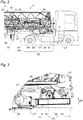
- the mast 2 supports a coupling element 26 provided with a coupling pin 27 suitable for coupling to a fifth wheel SE provided on a rear platform PA of a truck CT tractor; which rear platform PA resting, by means of a suspension device, on a single or double axle device supporting a rear wheelset RA.
- the crane 1 can be transported on a fifth wheel, as shown in the Figure 1 , with the coupling pin 27 coupled to the fifth wheel SE of the tractor truck CT.
- the turntable 4 and the frame 40 are located at the rear of the mast 2, while the coupling element 26 is located at the front of the mast 2 in a front coupling zone 28 dimensioned to come above the rear platform PA of the tractor truck CT for transport on a fifth wheel.
- the front coupling zone 28 of the mast 2 is arranged vertically above the rotating platform 4.
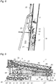
- This front coupling zone 28 of the mast 2 corresponds to the upper end portion 25 of the lower mast segment 21, this upper end portion 25 being connected to the upper mast segment 22 opposite to the rotating platform 4.
- the coupling element 26 is fixed on this upper end portion 25 of the lower mast segment 21, with the coupling element 7 which is located on the underside of this upper end portion 25 at the bottom. transport configuration.
- the crane 1 also comprises a mooring system 5 which is also fixed on this upper end portion 25 of the lower mast segment 21, therefore in the front coupling zone 28 of the mast 2, with this system of mooring 5 which is located on the underside of this upper end portion 25 in the transport configuration.
- the function of this mooring system 5 is to temporarily moor a removable ballast element 6 on the front coupling zone 28 of the mast 2, under the mast 2, in the transport configuration.
- the removable ballast element 6 is fixed under the mast 2, above the rear platform PA of the tractor truck CT, so that this removable ballast element 6 loads the rear wheel set RA tractor truck CT and therefore contributes to improving the stability of the convoy on the road.
- this removable ballast element 6 can be detached from the mooring system 5, so that in working configuration it can be mounted on the turntable 4, to increase the load capacity of the crane 1.
- the mooring system 5 is located in front of the coupling element 26 so that, in the transport configuration, the coupling element 26 is located between the turntable 4 and the 'removable ballast element 6.
- the mooring system 5 and the removable ballast element 6 are located at least partially below the intermediate joint 23 which is located at the front.
- the mooring system 5 is located above the coupling element 26, between the coupling element 26 and the intermediate articulation 23.
- the mooring system is located behind the hitching element 26, while remaining in the front hitching zone 28 of the mast 2, so that the removable ballast element would be located. between the turntable 4 and the coupling element 26.
- the mooring system 5 is thus fixed to the upper end portion 25 of the lower mast segment 21, being located on the underside of this upper end portion 25 in the transport configuration.
- the removable ballast element 6 is fixed below this upper end portion 25 of the lower mast segment 21 in the transport configuration.
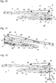
- the removable weight element 6 comprises a thin weight body 60, in the sense that this weight body 60, when moored on the mast 2 by means of the mooring system 5 in the transport configuration, has a thickness EP measured in a vertical direction, a length LO measured in a longitudinal direction before behind, and a width measured in a transverse direction from right to left, where the thickness EP is less than the width and the length LO.
- This ballast body 60 also has a general "U" shape, also called a horseshoe shape, with the opening of the "U" facing the rear.
- This removable ballast element 6 also comprises, projecting from an upper face of the ballast body 60, mooring members 61 which are in the form of mooring lugs and which are provided with respective slots 62; these slots 62 being oblong and vertical in the transport configuration.
- the removable ballast element comprises two mooring members 61 on the rear and a mooring member 61 on the front, with symmetry on either side of a vertical median plane, this vertical median plane passing through the mooring member 61 at the front and passing between the two mooring members 61 at the rear.
- the mooring system 5 comprises supports 51 suitable for supporting the respective mooring members 61 of the removable ballast element 6, each support 51 being integral with the mast 2 and provided with a hole.
- the supports 51 are more precisely fixed to the upper end portion 25 of the lower mast segment 21.
- the removable ballast element 6 comprises at least one slinging member 63 for fixing a lifting cable suitable for lifting the ballast element. removable 6 from the ground.
- the slinging member 63 is vertically aligned, when lifting the removable ballast element 6, with the center of gravity of the removable ballast element 6, so that the ballast element removable 6 remains horizontal during lifting (or lowering).
- the slinging member 63 is fixed to a cross member 64 which extends between the two branches of the “U” of the weighting body 60; this ballast body 60 having, as a reminder, a general "U" shape.
- the slinging member 63 is thus located in the vertical median plane which passes through the mooring member 61 at the front.
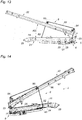
- the crane 1 comprises a detection system 7 which is arranged on the mast 2, at the level of the mooring system 5, to detect, when lifting the removable ballast element 6 from the ground up to the level of the mooring system 5.
- this detection system 7 is also provided to detect when the removable ballast element 6 is positioned in an over-stroke position (illustrated in Figure 16 (a) ) located vertically above the mooring position, to control an automatic stop of the lifting of the removable ballast element 6.
- this detection system 7 comprises a rocker 70 mounted movably in rotation on the mast 2, and more specifically mounted movably on a cross member 250 integral with the upper end portion 25 of the lower mast segment 21.
- This rocker 70 is intended for be pushed by the removable ballast element 6 when it is lifted from the ground 6.
- the rocker 70 is pushed by the cross member 64 which supports the slinging member 63.
- rocker 70 In the absence of a thrust exerted by the removable ballast element 6 on the rocker 70, therefore when the removable ballast element 6 is below the docking position, the rocker 70 is in a position of rest (or neutral position) visible on the Figure 16 (a) .
- An elastic return element may be provided which solicits the rocker 70 to the rest position, in the absence of a thrust exerted by the removable ballast element 6, or alternatively the rocker 70 naturally returns to the rest position under the effect of its own weight.
- the detection system 7 comprises a mooring sensor 71 provided to detect the presence of the rocker 70 in a position corresponding to the mooring position of the removable ballast element 6.
- This sensor The mooring 71 is a presence detection sensor or proximity sensor, and is for example an optical sensor (without contact) or a mechanical sensor (with contact).
- the detection system 7 comprises an over-stroke sensor 72, disposed vertically above the mooring sensor 71, and provided to detect the presence of the rocker 70 in a position corresponding to the over-stroke position of the removable ballast element 6.
- the mooring sensor 71 and the over-travel sensor 72 are for example both fixed to a plate 73 fixed to the cross member 250.
- the docking position corresponds to a position in which the holes of the support 51 coincide substantially with the middle of the slots 62 of the docking members 61, thus making it possible to easily insert the locking pins 62.
- the removable ballast element 6 has raised the rocker 70 so that it is placed in front of the mooring sensor 71, but not in front of the over-stroke sensor 72.
- the mooring sensor 71 detects the rocker 70, and at the same time the over-stroke sensor 72 does not detect the rocker 70, which therefore allows the detection of the docking position.
- the over-stroke position corresponds to a position in which the holes in the support 51 coincide substantially with the lower ends of the slots 62 of the mooring members 61.
- the removable ballast element 6 has raised the rocker 70 so that it is placed in front of the mooring sensor 71 and also in front of the over-stroke sensor 72.
- the mooring sensor 71 detects the rocker 70, and at the same time the over-stroke sensor 72 also detects the rocker 70, which therefore allows the detection of the over-stroke position.
- the crane 1 In this neutral configuration, the crane 1 can be folded / unfolded, be in transport or working configuration, without the front auxiliary lifting system 8 interfering.
- the elbow 87 is provided to maintain a reserve of length for the front lifting cable 80, in order to be able to fix its front end 81 to the removable ballast element 6.
- the removable ballast element 6 is mounted on the turntable 4, to increase the load capacity of the crane 1.
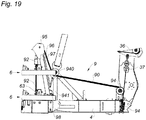
- an external lifting device or alternatively to employ a rear auxiliary lifting system 9 which is described below with reference to Figures 7 and 17 to 19 .
- the jib arm 96 is locked in a raised, almost vertical position, by means of a locking hook 98.
- the lifting of the load lifting hook 37 (by controlling the motorized lifting system of the crane 1) allows the rear lifting cable 90 to lift the removable ballast element 6 from the ground to the rotating platform 40 , and the jib arm 96 allows the removable ballast element 6 to be tilted above the rotating platform 40, before lowering the removable ballast element 6 still by means of the load lifting hook 37.
- the crane 1 can, optionally, include a towing drawbar 10 which is mounted on the mast 2, and more specifically on the lower mast segment 21.
- This towing drawbar 10 has its own coupling head 11. to be coupled to an ER towing element of a CR towing truck (trailer type) as shown on the Figure 5 .
- the coupling head 11 of the tow bar 10 is located opposite the removable ballast element 6, and even partially in the opening of the “U” facing the rear of the ballast body 60; this ballast body 60 having, as a reminder, a general "U" shape.
- the removable ballast element 6 cannot be moored on the mast 2 by means of the mooring system 5, and in this case it can for example be loaded into the tow truck CR .
Applications Claiming Priority (1)
| Application Number | Priority Date | Filing Date | Title |
|---|---|---|---|
| FR2003113A FR3108596B1 (fr) | 2020-03-30 | 2020-03-30 | Grue à montage automatisé comprenant un élément de lestage amovible pour un transport sur sellette |
Publications (2)
| Publication Number | Publication Date |
|---|---|
| EP3889094A1 true EP3889094A1 (de) | 2021-10-06 |
| EP3889094B1 EP3889094B1 (de) | 2023-02-15 |
Family
ID=70614299
Family Applications (1)
| Application Number | Title | Priority Date | Filing Date |
|---|---|---|---|
| EP21164473.7A Active EP3889094B1 (de) | 2020-03-30 | 2021-03-24 | Kran mit automatisierter montage, der ein abnehmbares ballastelement für den transport auf einem sattel umfasst |
Country Status (4)
| Country | Link |
|---|---|
| US (1) | US11565917B2 (de) |
| EP (1) | EP3889094B1 (de) |
| ES (1) | ES2943238T3 (de) |
| FR (1) | FR3108596B1 (de) |
Citations (3)
| Publication number | Priority date | Publication date | Assignee | Title |
|---|---|---|---|---|
| GB798547A (en) * | 1955-02-21 | 1958-07-23 | Chantiers & Ateliers De Constr | Tower crane |
| FR89990E (fr) * | 1966-05-04 | 1967-09-22 | Grue à tour transportable à montage rapide | |
| WO2001044097A1 (de) | 1999-12-06 | 2001-06-21 | Köck, Elke | Fahrwerk für eine weitausladende arbeitsvorrichtung, insbesondere für einen bauhochkran |
Family Cites Families (2)
| Publication number | Priority date | Publication date | Assignee | Title |
|---|---|---|---|---|
| ES2198086T3 (es) * | 1997-12-09 | 2004-01-16 | Kock, Elke | Mecanismo de rodadura para un dispositivo de trabajo ampliamente volado, especialmente para una grua alta de construccion. |
| FR3040990B1 (fr) * | 2015-09-10 | 2017-10-13 | Thierry Tenailleau | Grue a montage rapide et non autolestee |
-
2020
- 2020-03-30 FR FR2003113A patent/FR3108596B1/fr active Active
-
2021
- 2021-03-24 EP EP21164473.7A patent/EP3889094B1/de active Active
- 2021-03-24 ES ES21164473T patent/ES2943238T3/es active Active
- 2021-03-29 US US17/216,571 patent/US11565917B2/en active Active
Patent Citations (3)
| Publication number | Priority date | Publication date | Assignee | Title |
|---|---|---|---|---|
| GB798547A (en) * | 1955-02-21 | 1958-07-23 | Chantiers & Ateliers De Constr | Tower crane |
| FR89990E (fr) * | 1966-05-04 | 1967-09-22 | Grue à tour transportable à montage rapide | |
| WO2001044097A1 (de) | 1999-12-06 | 2001-06-21 | Köck, Elke | Fahrwerk für eine weitausladende arbeitsvorrichtung, insbesondere für einen bauhochkran |
Also Published As
| Publication number | Publication date |
|---|---|
| FR3108596B1 (fr) | 2022-04-15 |
| ES2943238T3 (es) | 2023-06-12 |
| FR3108596A1 (fr) | 2021-10-01 |
| US11565917B2 (en) | 2023-01-31 |
| EP3889094B1 (de) | 2023-02-15 |
| US20210300733A1 (en) | 2021-09-30 |
Similar Documents
| Publication | Publication Date | Title |
|---|---|---|
| EP0183632B1 (de) | Wagentransporter mit individuellen quertragenden Elementen | |
| EP0584026B1 (de) | Kupplungseinheit zwischen zwei aufeinander folgenden Waggons und einem gemeinsamen Drehgestell | |
| FR2957022A1 (fr) | Traverse porteuse amovible equipee d'une sellette de hauteur reglable pour le soutien d'une semi-remoque pendant son chargement, son transport ferroviaire et son dechargement. | |
| EP3838666B1 (de) | Halterung zum anheben von behältern an den oberen behälteröffnungen | |
| FR3068325A1 (fr) | Ensemble deposable de chargement/dechargement d'une semi-remorque sur une structure ferroviaire de wagon-poche | |
| FR2551401A1 (fr) | Vehicule utilitaire dote d'un dispositif de chargement et de dechargement par roulement et basculement | |
| EP3889094B1 (de) | Kran mit automatisierter montage, der ein abnehmbares ballastelement für den transport auf einem sattel umfasst | |
| FR2690883A1 (fr) | Mécanisme d'actionnement pour le bras arrière basculant de levage/tractage d'un véhicule de dépannage. | |
| EP0870726B1 (de) | Selbstaufrichtender Kran mit seitlich zusammenklappbarem Ausleger in der Transportstellung | |
| EP2505429B1 (de) | Verfahren zur Regulierung des Achsabstands einer rollenden Einheit, die mindestens zwei Fördervorrichtungen für Container umfasst | |
| EP3141517B1 (de) | Schnellmontage-kran ohne ballastierung | |
| FR2611682A1 (fr) | Support ou passerelle deplacable pour amener un vehicule en position surelevee | |
| EP1209027B1 (de) | Leichtes Pritschenfahrzeug mit abnehmbarem Behälter | |
| FR2940937A1 (fr) | Dispositif de support destine a faciliter le chargement d'un caisson ou d'un plateau sur une plate-forme | |
| WO2022259194A1 (fr) | Ensemble de dépannage-remorquage pour véhicule remorqueur, et véhicule remorqueur le comprenant | |
| EP0274918A1 (de) | Transportfahrzeug für schnelles Laden und Entladen und Lastträgerstruktur, wie eine Bühne, dafür | |
| FR2563204A1 (fr) | Accessoire pour chariot a fourche, et procede de dechargement utilisant cet accessoire | |
| EP3577051A1 (de) | Bodenkran, vorrichtung zur installation solch eines krans auf einem container, feldwerkstatt und verfahren zum aufbau einer feldwerkstatt mit solch einem kran | |
| EP2990263B1 (de) | Strassentransportfahrzeug mit einer haltestruktur zum beladen mit automatischem ein- und ausklinksystem | |
| FR3133351A1 (fr) | Vehicule de voirie multifonctions comportant des moyens pour le changement rapide d’outils | |
| EP4281618A1 (de) | Anordnung und verfahren zum automatischen ausrichten von schienen | |
| FR2649052A1 (fr) | Dispositif de stabilisation pour un vehicule porteur, lors de l'enlevement ou de la pose d'une charge telle qu'un silo mobile charge | |
| FR2759040A1 (fr) | Procede et equipement de fonctionnalite relationnelle entre la fleche d'un engin de manutention et sa structure porteuse | |
| FR2831862A1 (fr) | Leve conteneur | |
| WO1995028296A1 (fr) | Dispositif de manutention et d'elevation d'une charge portee par un vehicule ou par une remorque |
Legal Events
| Date | Code | Title | Description |
|---|---|---|---|
| PUAI | Public reference made under article 153(3) epc to a published international application that has entered the european phase |
Free format text: ORIGINAL CODE: 0009012 |
|
| STAA | Information on the status of an ep patent application or granted ep patent |
Free format text: STATUS: THE APPLICATION HAS BEEN PUBLISHED |
|
| AK | Designated contracting states |
Kind code of ref document: A1 Designated state(s): AL AT BE BG CH CY CZ DE DK EE ES FI FR GB GR HR HU IE IS IT LI LT LU LV MC MK MT NL NO PL PT RO RS SE SI SK SM TR |
|
| STAA | Information on the status of an ep patent application or granted ep patent |
Free format text: STATUS: REQUEST FOR EXAMINATION WAS MADE |
|
| 17P | Request for examination filed |
Effective date: 20220323 |
|
| RBV | Designated contracting states (corrected) |
Designated state(s): AL AT BE BG CH CY CZ DE DK EE ES FI FR GB GR HR HU IE IS IT LI LT LU LV MC MK MT NL NO PL PT RO RS SE SI SK SM TR |
|
| RIC1 | Information provided on ipc code assigned before grant |
Ipc: B66C 23/34 20060101AFI20220627BHEP |
|
| GRAP | Despatch of communication of intention to grant a patent |
Free format text: ORIGINAL CODE: EPIDOSNIGR1 |
|
| STAA | Information on the status of an ep patent application or granted ep patent |
Free format text: STATUS: GRANT OF PATENT IS INTENDED |
|
| INTG | Intention to grant announced |
Effective date: 20221021 |
|
| GRAS | Grant fee paid |
Free format text: ORIGINAL CODE: EPIDOSNIGR3 |
|
| GRAA | (expected) grant |
Free format text: ORIGINAL CODE: 0009210 |
|
| STAA | Information on the status of an ep patent application or granted ep patent |
Free format text: STATUS: THE PATENT HAS BEEN GRANTED |
|
| AK | Designated contracting states |
Kind code of ref document: B1 Designated state(s): AL AT BE BG CH CY CZ DE DK EE ES FI FR GB GR HR HU IE IS IT LI LT LU LV MC MK MT NL NO PL PT RO RS SE SI SK SM TR |
|
| REG | Reference to a national code |
Ref country code: CH Ref legal event code: EP Ref country code: GB Ref legal event code: FG4D Free format text: NOT ENGLISH |
|
| REG | Reference to a national code |
Ref country code: DE Ref legal event code: R096 Ref document number: 602021001383 Country of ref document: DE |
|
| REG | Reference to a national code |
Ref country code: AT Ref legal event code: REF Ref document number: 1548160 Country of ref document: AT Kind code of ref document: T Effective date: 20230315 Ref country code: IE Ref legal event code: FG4D Free format text: LANGUAGE OF EP DOCUMENT: FRENCH |
|
| PGFP | Annual fee paid to national office [announced via postgrant information from national office to epo] |
Ref country code: DE Payment date: 20230321 Year of fee payment: 3 |
|
| REG | Reference to a national code |
Ref country code: LT Ref legal event code: MG9D Ref country code: ES Ref legal event code: FG2A Ref document number: 2943238 Country of ref document: ES Kind code of ref document: T3 Effective date: 20230612 |
|
| REG | Reference to a national code |
Ref country code: NL Ref legal event code: MP Effective date: 20230215 |
|
| REG | Reference to a national code |
Ref country code: AT Ref legal event code: MK05 Ref document number: 1548160 Country of ref document: AT Kind code of ref document: T Effective date: 20230215 |
|
| PG25 | Lapsed in a contracting state [announced via postgrant information from national office to epo] |
Ref country code: RS Free format text: LAPSE BECAUSE OF FAILURE TO SUBMIT A TRANSLATION OF THE DESCRIPTION OR TO PAY THE FEE WITHIN THE PRESCRIBED TIME-LIMIT Effective date: 20230215 Ref country code: PT Free format text: LAPSE BECAUSE OF FAILURE TO SUBMIT A TRANSLATION OF THE DESCRIPTION OR TO PAY THE FEE WITHIN THE PRESCRIBED TIME-LIMIT Effective date: 20230615 Ref country code: NO Free format text: LAPSE BECAUSE OF FAILURE TO SUBMIT A TRANSLATION OF THE DESCRIPTION OR TO PAY THE FEE WITHIN THE PRESCRIBED TIME-LIMIT Effective date: 20230515 Ref country code: NL Free format text: LAPSE BECAUSE OF FAILURE TO SUBMIT A TRANSLATION OF THE DESCRIPTION OR TO PAY THE FEE WITHIN THE PRESCRIBED TIME-LIMIT Effective date: 20230215 Ref country code: LV Free format text: LAPSE BECAUSE OF FAILURE TO SUBMIT A TRANSLATION OF THE DESCRIPTION OR TO PAY THE FEE WITHIN THE PRESCRIBED TIME-LIMIT Effective date: 20230215 Ref country code: LT Free format text: LAPSE BECAUSE OF FAILURE TO SUBMIT A TRANSLATION OF THE DESCRIPTION OR TO PAY THE FEE WITHIN THE PRESCRIBED TIME-LIMIT Effective date: 20230215 Ref country code: HR Free format text: LAPSE BECAUSE OF FAILURE TO SUBMIT A TRANSLATION OF THE DESCRIPTION OR TO PAY THE FEE WITHIN THE PRESCRIBED TIME-LIMIT Effective date: 20230215 Ref country code: AT Free format text: LAPSE BECAUSE OF FAILURE TO SUBMIT A TRANSLATION OF THE DESCRIPTION OR TO PAY THE FEE WITHIN THE PRESCRIBED TIME-LIMIT Effective date: 20230215 |
|
| PGFP | Annual fee paid to national office [announced via postgrant information from national office to epo] |
Ref country code: IT Payment date: 20230331 Year of fee payment: 3 Ref country code: FR Payment date: 20230410 Year of fee payment: 3 Ref country code: ES Payment date: 20230529 Year of fee payment: 3 |
|
| PG25 | Lapsed in a contracting state [announced via postgrant information from national office to epo] |
Ref country code: SE Free format text: LAPSE BECAUSE OF FAILURE TO SUBMIT A TRANSLATION OF THE DESCRIPTION OR TO PAY THE FEE WITHIN THE PRESCRIBED TIME-LIMIT Effective date: 20230215 Ref country code: PL Free format text: LAPSE BECAUSE OF FAILURE TO SUBMIT A TRANSLATION OF THE DESCRIPTION OR TO PAY THE FEE WITHIN THE PRESCRIBED TIME-LIMIT Effective date: 20230215 Ref country code: IS Free format text: LAPSE BECAUSE OF FAILURE TO SUBMIT A TRANSLATION OF THE DESCRIPTION OR TO PAY THE FEE WITHIN THE PRESCRIBED TIME-LIMIT Effective date: 20230615 Ref country code: GR Free format text: LAPSE BECAUSE OF FAILURE TO SUBMIT A TRANSLATION OF THE DESCRIPTION OR TO PAY THE FEE WITHIN THE PRESCRIBED TIME-LIMIT Effective date: 20230516 Ref country code: FI Free format text: LAPSE BECAUSE OF FAILURE TO SUBMIT A TRANSLATION OF THE DESCRIPTION OR TO PAY THE FEE WITHIN THE PRESCRIBED TIME-LIMIT Effective date: 20230215 |
|
| PG25 | Lapsed in a contracting state [announced via postgrant information from national office to epo] |
Ref country code: SM Free format text: LAPSE BECAUSE OF FAILURE TO SUBMIT A TRANSLATION OF THE DESCRIPTION OR TO PAY THE FEE WITHIN THE PRESCRIBED TIME-LIMIT Effective date: 20230215 Ref country code: RO Free format text: LAPSE BECAUSE OF FAILURE TO SUBMIT A TRANSLATION OF THE DESCRIPTION OR TO PAY THE FEE WITHIN THE PRESCRIBED TIME-LIMIT Effective date: 20230215 Ref country code: EE Free format text: LAPSE BECAUSE OF FAILURE TO SUBMIT A TRANSLATION OF THE DESCRIPTION OR TO PAY THE FEE WITHIN THE PRESCRIBED TIME-LIMIT Effective date: 20230215 Ref country code: DK Free format text: LAPSE BECAUSE OF FAILURE TO SUBMIT A TRANSLATION OF THE DESCRIPTION OR TO PAY THE FEE WITHIN THE PRESCRIBED TIME-LIMIT Effective date: 20230215 Ref country code: CZ Free format text: LAPSE BECAUSE OF FAILURE TO SUBMIT A TRANSLATION OF THE DESCRIPTION OR TO PAY THE FEE WITHIN THE PRESCRIBED TIME-LIMIT Effective date: 20230215 |
|
| REG | Reference to a national code |
Ref country code: DE Ref legal event code: R097 Ref document number: 602021001383 Country of ref document: DE |
|
| PG25 | Lapsed in a contracting state [announced via postgrant information from national office to epo] |
Ref country code: SK Free format text: LAPSE BECAUSE OF FAILURE TO SUBMIT A TRANSLATION OF THE DESCRIPTION OR TO PAY THE FEE WITHIN THE PRESCRIBED TIME-LIMIT Effective date: 20230215 |
|
| REG | Reference to a national code |
Ref country code: BE Ref legal event code: MM Effective date: 20230331 |
|
| PLBE | No opposition filed within time limit |
Free format text: ORIGINAL CODE: 0009261 |
|
| STAA | Information on the status of an ep patent application or granted ep patent |
Free format text: STATUS: NO OPPOSITION FILED WITHIN TIME LIMIT |
|
| PG25 | Lapsed in a contracting state [announced via postgrant information from national office to epo] |
Ref country code: LU Free format text: LAPSE BECAUSE OF NON-PAYMENT OF DUE FEES Effective date: 20230324 |
|
| PG25 | Lapsed in a contracting state [announced via postgrant information from national office to epo] |
Ref country code: MC Free format text: LAPSE BECAUSE OF FAILURE TO SUBMIT A TRANSLATION OF THE DESCRIPTION OR TO PAY THE FEE WITHIN THE PRESCRIBED TIME-LIMIT Effective date: 20230215 |
|
| REG | Reference to a national code |
Ref country code: IE Ref legal event code: MM4A |
|
| 26N | No opposition filed |
Effective date: 20231116 |
|
| PG25 | Lapsed in a contracting state [announced via postgrant information from national office to epo] |
Ref country code: SI Free format text: LAPSE BECAUSE OF FAILURE TO SUBMIT A TRANSLATION OF THE DESCRIPTION OR TO PAY THE FEE WITHIN THE PRESCRIBED TIME-LIMIT Effective date: 20230215 Ref country code: MC Free format text: LAPSE BECAUSE OF FAILURE TO SUBMIT A TRANSLATION OF THE DESCRIPTION OR TO PAY THE FEE WITHIN THE PRESCRIBED TIME-LIMIT Effective date: 20230215 Ref country code: IE Free format text: LAPSE BECAUSE OF NON-PAYMENT OF DUE FEES Effective date: 20230324 |
|
| PG25 | Lapsed in a contracting state [announced via postgrant information from national office to epo] |
Ref country code: BE Free format text: LAPSE BECAUSE OF NON-PAYMENT OF DUE FEES Effective date: 20230331 |