EP3889078A1 - Einrichtung zum sammeln von milchprobeflaschen - Google Patents
Einrichtung zum sammeln von milchprobeflaschen Download PDFInfo
- Publication number
- EP3889078A1 EP3889078A1 EP21000067.5A EP21000067A EP3889078A1 EP 3889078 A1 EP3889078 A1 EP 3889078A1 EP 21000067 A EP21000067 A EP 21000067A EP 3889078 A1 EP3889078 A1 EP 3889078A1
- Authority
- EP
- European Patent Office
- Prior art keywords
- receiving space
- magazine
- sample bottles
- milk
- milk sample
- Prior art date
- Legal status (The legal status is an assumption and is not a legal conclusion. Google has not performed a legal analysis and makes no representation as to the accuracy of the status listed.)
- Granted
Links
Images



Classifications
-
- B—PERFORMING OPERATIONS; TRANSPORTING
- B65—CONVEYING; PACKING; STORING; HANDLING THIN OR FILAMENTARY MATERIAL
- B65G—TRANSPORT OR STORAGE DEVICES, e.g. CONVEYORS FOR LOADING OR TIPPING, SHOP CONVEYOR SYSTEMS OR PNEUMATIC TUBE CONVEYORS
- B65G29/00—Rotary conveyors, e.g. rotating discs, arms, star-wheels or cones
-
- A—HUMAN NECESSITIES
- A01—AGRICULTURE; FORESTRY; ANIMAL HUSBANDRY; HUNTING; TRAPPING; FISHING
- A01J—MANUFACTURE OF DAIRY PRODUCTS
- A01J5/00—Milking machines or devices
- A01J5/04—Milking machines or devices with pneumatic manipulation of teats
- A01J5/045—Taking milk-samples
Definitions
- the invention relates to a device for collecting milk sample bottles according to the preamble of claim 1.
- Such facilities are in use on milk collection vehicles with automatic sample bottle filling.
- two round magazines are used. Such a round magazine can hold up to 72 empty sample bottles. They are guided to a sample bottle filling position via a sample bottle transport and, after the sample has been taken, transported to the second empty round magazine. After the milk collection tour has been completed, there are up to 72 milk sample bottles filled with milk samples in one of the round magazines. This round magazine is handed over to milk testing laboratories, which analyze the milk samples fully automatically in an optimal way.
- Simpler devices are also known which contain, for example, only 16 milk sampling bottles. Since round sample bottle magazines are still used for transport to the milk test laboratories and must also be used for an automated process in the milk test laboratories, the problem arises that the filled milk sample bottles have to be sorted into the round magazine by hand at the end of the milk collection tour.
- the invention is based on the object of designing the generic device in such a way that it enables automatic sorting into the magazine with only a small footprint.
- the magazine of the device according to the invention is designed in such a way that the milk sample bottles located in the receiving space can be discharged via the outlet and filled with the milk sample.
- a barcode or a transponder is applied to the milk sample bottle, which identifies the milk contained in the sample bottle with regard to time, place and the like.
- the filled and labeled milk sample bottles are then conveyed back into the receiving space of the magazine via the inlet. Since the inlet and the outlet of the magazine are blocked against each other, the milk sampling bottles can be introduced through the inlet without mutual hindrance and led out of the receiving space of the magazine through the outlet. Since there is only one magazine, the device can be made very compact, so that it can also be provided on collection vehicles in which only a small installation space is available for the device.
- the milk sample bottles can be led out one after the other through the outlet from the receiving space of the magazine and transported to an identification and filling position.
- the milk sample bottle filled and labeled in this way can then be transported back into the receiving space via the inlet.
- the outlet is advantageously provided with a guide with which the discharge of the milk sample bottle from the receiving space is facilitated.
- the milk sampling bottle can be reliably removed from the magazine and transported on for identification and filling.
- the guidance of the outlet advantageously ensures that the milk sampling bottle that has been discharged does not come into contact with the milk sampling bottle that has been introduced through the inlet, is filled with milk and is identified.
- the radial width of the annular receiving space corresponds approximately to the diameter of the milk sample bottle, which in this way is properly guided between the two ring walls.
- the milk sample bottles are arranged one behind the other in such a way that they advantageously lie against one another.
- the ring-shaped receiving space is optimally used.
- the milk sample bottles are advantageously on a rotatably driven base which is rotatable with respect to the two ring walls.
- the milk sample bottles are transported within the receiving space by means of the base.
- the outlet of the magazine is advantageously provided in the outer ring wall.
- the outlet is formed by an opening in the outer ring wall through which the milk sampling bottle can be moved out of the receiving space and transported to the identification and filling position.
- the inlet for the filled and identified milk sampling bottles is also advantageously provided in the outer ring wall.
- the recording space can also have an angular outline.
- the receiving space is advantageously delimited by a rectangular frame.
- At least one partition is advantageously located in the receiving space. They divide the receiving space into at least two receiving space sections. The milk sampling bottles are located in these receiving space sections.
- the receiving space sections are advantageously connected to one another at both ends of the partition wall.
- the milk sample bottles at the end of the partition can be transported from one receiving space section into the other receiving space section.
- the outlet which is designed in such a way that it is separated from the inlet or blocked from it. This is why the milk sampling bottles can also be transferred in and out simultaneously with this rectangular configuration of the receiving space without the milk sampling bottles interfering with one another.
- the device according to the invention is advantageously designed in such a way that at least one transport system is assigned to the magazine in order to smuggle the milk sample bottles into the receiving space.
- the transport system is preferably located in the immediate vicinity of the magazine, in particular in the immediate vicinity of the inlet and outlet. Therefore, the milk sampling bottles only have to cover a very short distance in order to be discharged from the magazine or to be introduced into the magazine.
- a simple transport of the milk sample bottles during the inward and outward transfer results when the transport system has a slide for the introduction and a slide for the removal of the discharged milk sample bottles.
- the milk sample bottles can be reliably transported using the slide.
- the slide is advantageously provided with a receptacle for the milk sampling bottle.
- This receptacle is designed in such a way that the milk sample bottle cannot fall over during transport.
- the slide can preferably be designed in such a way that its bottom has a recess into which the milk sample bottle is placed.
- the diameter of the recess then corresponds approximately to the outer diameter of the bottom area of the milk sample bottle.
- the sliders do not have to be very high. It is sufficient if they are only so high that the milk sample bottle placed in the slide cannot fall over.
- a drive is provided with which the bottom of the receiving space can be rotatably driven.
- the floor of the receiving space is designed so that the milk sample bottles stand on the floor in the receiving space.
- the establishment according to the Figures 1 to 7 has a magazine 1, which is designed as a round magazine in this embodiment.
- a transport system 2 is assigned to the magazine 1, with which sample bottles 3 can be removed from the magazine 1 and fed to it.
- the facility is located on milk collection vehicles that are used to collect milk from the production facilities.
- Delivered milk is filled with a milk sample in the sample bottle 3, which is later tested in a milk testing laboratory.
- the device has a carrier 4 on which the magazine 1 and the transport system 2 are arranged.
- the magazine 1 has a bottom 18 which can be driven rotatably about an axis perpendicular to the upper side of the carrier ( Fig. 5 and 7th ).
- the bottom 18 is seated in a rotationally fixed manner on an axis 5. It protrudes through an upper support wall 6 upwards. Below the support wall 6, the axle 5 is connected to a corresponding drive 7 ( Fig. 6 ), with which the axis 5 is rotatably driven.
- the drive 7 is accommodated in a receptacle 8 which is delimited in the direction of the magazine 1 by the support wall 6.
- Side walls 9 adjoin the edge of the carrier wall 6 and laterally delimit the receptacle 8.
- the side walls 9 are of the same height and protect the drive 7 accommodated in the receptacle 8 in the installed position of the device.
- the receptacle 8 is open on its side opposite the support wall 6. This allows easy access to the drive 7 if it needs to be repaired, serviced or replaced.
- the receptacle 8 can of course be closed by a base.
- a lifting unit 39 for lifting the sample bottles 3 and a drive motor 40 for a rotating bottle box (not shown) are also accommodated in the receptacle 8.
- the sample bottles 3 can thus be rotated in order to be able to reliably detect barcodes attached to their outside by means of a barcode reader.
- the sample bottles 3 can be raised into a filling position (cf. Fig. 2 to 4 and 7th ).
- the magazine 1 has an annular receiving space 10 for the sample bottles 3. It is delimited in the radial direction by two annular walls 11, 12 lying coaxially to one another. The distance between the two ring walls 11, 12 essentially corresponds to the diameter of the sample bottles 3, so that they are reliably secured against tipping over in the receiving space 10.
- the outer ring wall 11 has for most of its circumference parallel to the axis of rotation 5 and spaced apart slots 13 which end at a distance from the upper edge 14 of the ring wall 11 and extend to the lower edge 15 of the ring wall 11.
- the slots 13 are used to save material and weight.
- the two ring walls 12, 13 are advantageously connected to one another via transverse webs 16. They are located at the upper edge of the two ring walls 11, 12.
- the webs 16 are advantageously integrally connected to the inner ring wall 12 and extend over the receiving space 10 to the outer ring wall 11.
- the free end 17 of the webs 16 is angled at right angles and rests on the outside of the outer ring wall 11.
- the free end of the web 17 is preferably firmly connected to the annular wall 11, for example glued.
- the ring walls 11, 12 are held on the carrier 4 in a suitable manner.
- Both ring walls 11, 12 extend perpendicular to the floor 18, which delimits the receiving space 10 downwards.
- the sample bottles 3 stand in the receiving space 10 on the floor 18.
- the magazine 1 has an in / out area 19 via which the sample bottles 3 are transferred to the magazine 1 or removed from it.
- the inward transfer area 19a is separated from the outward transfer area 19b by a locking bracket 20 ( Fig. 5 ).
- the sample bottles 3 are fed to the magazine 1 with the transport system 2.
- the transport system is also used for transporting the sample bottle 3 to an identification and filling position 21 ( Fig. 5 and 7th ).
- a drive 22, advantageously formed by a piston-cylinder unit, is provided, which is arranged on the carrier 4 and with which the sample bottle 3 is pushed through the transfer area 19a into the receiving space 10 .
- the sample bottle 3 is advantageously inserted in the area outside the magazine 1 in a slide 24 which is provided with a receptacle 25 for the sample bottle and is moved approximately radially to the magazine 1 by the drive 22 so that the sample bottle 3 enters the receiving space 10 of the Magazine 1 arrives.
- the slide is then withdrawn by means of the drive 26.
- a sample bottle 3 is introduced into the receiving space 10 with the slide 24.
- the bottom 18 of the magazine 1 is rotated in such a way that the inward transfer area 19a is free for the inward transfer of the next sample bottle 3.
- the bottom 18 is thus rotated step by step.
- the locking bracket 20 has a curved or inclined guide surface 23 on its side facing the discharge area 19b ( Fig. 5 ), which ensures that the respective front sample bottle 3 is discharged from the receiving space 10 via this guide surface 23.
- the guide surface 23 extends approximately from the inner ring wall 12 to the edge of the discharge area 19b ( Fig. 5 ) and, viewed in the axial direction of the magazine 1, lies at an obtuse angle to the annular wall 12. As a result, the sample bottles 3 are reliably guided obliquely outwards to and through the discharge area 19b.
- the slide 24 is drive-connected to a slide drive 26 with which it can be extracted from the in Fig. 5
- the starting position shown can be transported with the sample bottle 3 inserted into the receptacle 25 to the barcode reading position 21, which is located in front of the drive 22.
- the sample bottle 3 is raised by means of the lifting unit 39. In the raised position, a sampling needle (not shown) is pierced into the sample bottle 3 and a representative milk sample is injected into the sample bottle 3. The sample bottle 3 is then lowered.
- the slide 24 has a bore 46 for the passage of a piston rod of the drive 22 ( Fig. 4 ), through which the piston rod can be moved in order to move the sample bottle 3 out of the receptacle 25 of the slide 24 into the transfer area 19a.
- the piston rod of the drive 22 is pulled out of the slide 24 and then the slide 24 with the slide drive 26 is moved into the starting position according to FIG Fig. 4 pulled back.
- the two drives 22, 26 have drive directions which are perpendicular to one another and which enable the sample bottle 3 to be transported easily.
- the slide 24 is arranged in the transfer position immediately adjacent to the discharge area 19b.
- the guide surface 23 of the locking bracket 20 is designed in such a way that it extends close to the slide 24.
- the guide surface 23 is advantageously arranged in such a way that it adjoins the inner wall of the receptacle 25 of the slide 24 at only a small distance. As a result, the discharged sample bottle 3 can be pushed reliably into the receptacle 25 of the slide 24.
- the identification / filling position 21 is used to detect the barcode or transponder attached to the side of the sample bottle 3. Because the sample bottle 3 is rotated about its axis by means of the drive 40, the barcode attached to the jacket of the sample bottle 3 can easily be brought into a position in which it can be detected by the barcode reader.
- the sample bottle can also have a transponder located in the bottom of the bottle, which is recorded accordingly.
- the outer ring wall 11 is provided with a corresponding opening in the inward / outward transfer area 19, so that the sample bottles 3 can be reliably conveyed in and out.
- the inner ring wall 12 can serve as a stop and guide, which ensures that the sample bottles 3 reliably get into the receiving space 10 of the magazine 1.
- the sample bottles are fed in and out radially.
- the inward / outward transfer area 19 in such a way that the sample bottles can be axially transferred into the receiving space 10 and out of the receiving space 10.
- grippers can be provided, for example, which insert the sample bottles from above into the receiving space 10 or lift them out of it.
- the inward / outward transfer area 19 is designed in such a way that the inward transfer area 19a is separated from the outward transfer area 19b. As in the case of the embodiment described, it is therefore possible to insert and remove sample bottles at the same time.
- other receiving devices for the sample bottles 3 can also be provided, for example star arms, the arms of which are provided with the corresponding receptacles 25 for the sample bottles 3 at the radially outer end. These star arms are then arranged in such a way that with one arm they lie opposite the inward transfer area 19a or the outward transfer area 19b and, after the inward transfer or outward transfer of the respective sample bottle, are rotated in such a way that the next arm is opposite the inward transfer area 19a or the outward transfer area 19b.
- the device described is characterized in particular by its simple structural design. It is only light in weight and requires little space in the collection vehicle. The inward and outward transfer of the sample bottles can be carried out fully automatically.
- the magazine 1 of the device is designed so that it is compatible with existing automation systems used in milk laboratories.
- the magazine has 1 rectangular shape. It is arranged on the carrier 4, which by way of example also has a rectangular outline.
- This exemplary embodiment shows that, instead of a round arrangement, an xy arrangement of the sample bottles 3 is also possible.
- the magazine 1 has longitudinal sides 27, 28 lying parallel to one another, which run parallel to the longitudinal sides 29, 30 of the carrier 4.
- the longitudinal sides 27, 28 and 29, 30 are connected to one another by narrow sides 31, 32 and 33, 34 running at right angles to them.
- the receiving space 10 of the magazine 1 is elongated in contrast to the previous embodiment and consists of two receiving areas 10a, 10b lying parallel to one another, which are separated from one another by a partition 35 over most of their length.
- the partition 35 ends at a distance from the narrow sides 31, 32 of the magazine 1 ( Fig. 8 ).
- transition areas 36, 37 are formed in the area of these narrow sides 31, 32, via which the sample bottles 3 can pass from one section 10a into the other section 10b of the receiving space 10.
- the inward / outward transfer area 19 for the sample bottles 3 is located in the transition area 37. It has the inward transfer area 19a ( Fig. 8 ), which is separated from the discharge area 19b by a locking element 38.
- the blocking element 38 has the guide surface 23 via which the respective sample bottle 3 is brought into the discharge area 19b.
- the sample bottle 3 - in contrast to the previous embodiment - is removed axially from the receiving space 10.
- the blocking element 38 ensures that the sample bottle cannot get out of the section 10b into the section 10a of the receiving space 8.
- each drives 41 to 44 are provided for inward and outward transfer in order to transport all the sample bottles 3 present one after the other into the barcode reading and filling position.
- the drives 41 to 44 are advantageously each piston-cylinder units, of which adjacent drives are each at right angles to one another ( Fig. 8 ).
- the lower row of sample bottles 3 is shifted to the right in direction P with the drive 43. This frees up a space in the lower row into which the drive 42 pushes the left sample bottle 3 of the upper row.
- the drive 41 With the drive 41, the upper row of sample bottles 3 can then be shifted in the opposite direction to P, as a result of which a space at the front in the shifting direction P becomes free.
- the drive 44 can be used to move the last sample bottle 3 in the lower row into the filling position at the inward transfer area 19a.
- conveyor belts can also be used as drives 41 to 44 for transporting the sample bottles 3.
- the sample bottles 3 are manually inserted into or removed from the magazine 1. It is also conceivable to use an interchangeable magazine for filling or removing the sample bottles 3, which has corresponding openings for the drives 41 to 44. In addition, at least one opening is provided in the bottom of the magazine for the rotating and / or lifting device at the filling position.
Landscapes
- Sampling And Sample Adjustment (AREA)
Abstract
Description
- Die Erfindung betrifft eine Einrichtung zum Sammeln von Milchprobeflaschen nach dem Oberbegriff des Anspruches 1.
- Solche Einrichtungen sind auf Milchsammelfahrzeugen mit einer automatischen Probeflaschenabfüllung im Einsatz.
- Bei bekannten Einrichtungen kommen zwei Rundmagazine zum Einsatz. Ein solches Rundmagazin kann bis zu 72 leere Probeflaschen enthalten. Sie werden über einen Probeflaschentransport zu einer Probenflaschenabfüllposition geführt und nach durchgeführter Probenahme in das zweite leere Rundmagazin transportiert. Nach Fertigstellung der Milchsammeltour befinden sich in dem einen Rundmagazin bis zu 72 mit Milchproben gefüllte Milchprobenflaschen. Dieses Rundmagazin wird an Milchprüflabore übergeben, welche die Milchproben optimaler Weise vollautomatisiert analysieren.
- Es sind auch einfachere Einrichtungen bekannt, die beispielsweise nur 16 Milchprobeflaschen enthalten. Da für den Transport zu den Milchprüflaboren nach wie vor Probeflaschenrundmagazine verwendet werden und in den Milchprüflaboren auch für einen automatisierten Ablauf verwendet werden müssen, tritt das Problem auf, dass die gefüllten Milchprobeflaschen am Ende der Milchsammeltour von Hand in das Rundmagazin einsortiert werden müssen.
- Der Erfindung liegt die Aufgabe zugrunde, die gattungsgemäße Einrichtung so auszubilden, dass sie bei nur geringem Platzbedarf eine automatische Einsortierung in das Magazin ermöglicht.
- Diese Aufgabe wird bei der gattungsgemäßen Einrichtung erfindungsgemäß mit den kennzeichnenden Merkmalen des Anspruches 1 gelöst.
- Das Magazin der erfindungsgemäßen Einrichtung ist so ausgebildet, dass die im Aufnahmeraum befindlichen Milchprobeflaschen über den Auslass ausgeschleust und mit der Milchprobe gefüllt werden können. Zur Identifikation der Milchprobe wird hierbei auf die Milchprobeflasche ein Barcode oder ein Transponder aufgebracht, der die in der Probeflasche enthaltene Milch hinsichtlich Zeit, Ort und dgl. kennzeichnet. Anschließend werden die gefüllten und gekennzeichneten Milchprobeflaschen über den Einlass zurück in den Aufnahmeraum des Magazins gefördert. Da der Einlass und der Auslass des Magazins gegeneinander gesperrt sind, können die Milchprobeflaschen ohne gegenseitige Behinderung durch den Einlass eingeschleust und durch den Auslass aus dem Aufnahmeraum des Magazins herausgeführt werden. Da nur ein Magazin vorhanden ist, kann die Einrichtung sehr kompakt ausgebildet sein, so dass sie auch an Sammelfahrzeugen vorgesehen sein kann, bei denen nur ein kleiner Einbauraum für die Einrichtung zur Verfügung steht.
- Die Milchprobeflaschen können nacheinander durch den Auslass aus dem Aufnahmeraum des Magazins herausgeführt und zu einer Identifikations- und Abfüllposition transportiert werden. Anschließend kann die so befüllte und gekennzeichnete Milchprobeflasche über den Einlass wieder zurück in den Aufnahmeraum transportiert werden.
- Vorteilhaft ist der Auslass mit einer Führung versehen, mit dem das Ausschleusen der Milchprobeflasche aus dem Aufnahmeraum erleichtert wird. Die Milchprobeflasche kann zuverlässig dem Magazin entnommen und zur Identifikation und Abfüllung weitertransportiert werden.
- Die Führung des Auslasses sorgt in vorteilhafter Weise dafür, dass die ausgeschleuste Milchprobeflasche nicht in Kontakt mit der durch den Einlass eingeschleusten, mit Milch gefüllten und identifizierten Milchprobeflasche gelangt.
- Eine vorteilhafte Ausführungsform ergibt sich, wenn der Aufnahmeraum des Magazins ringförmig ausgebildet ist. Dann kann auf kleinem Raum eine große Zahl von Milchprobeflaschen im Magazin untergebracht werden.
- Vorteilhaft ist bei der ringförmigen Gestaltung des Aufnahmeraumes, wenn er von zwei koaxialen Ringwänden begrenzt ist.
- Die radiale Breite des ringförmigen Aufnahmeraumes entspricht etwa dem Durchmesser der Milchprobeflasche, die auf diese Weise zwischen den beiden Ringwänden einwandfrei geführt ist.
- Im Aufnahmeraum sind die Milchprobeflaschen derart hintereinander angeordnet, dass sie vorteilhaft aneinander liegen. Dadurch wird der ringförmige Aufnahmeraum optimal genutzt.
- Die Milchprobeflaschen stehen vorteilhaft auf einem drehbar angetriebenen Boden auf, der gegenüber den beiden Ringwänden drehbar ist. Mittels des Bodens werden die Milchprobeflaschen innerhalb des Aufnahmeraumes transportiert.
- Der Auslass des Magazins ist vorteilhaft in der äußeren Ringwand vorgesehen. Der Auslass wird durch eine Öffnung in der äußeren Ringwand gebildet, durch die die Milchprobeflasche aus dem Aufnahmeraum herausbewegt und zur Identifikations- und Abfüllposition transportiert werden kann.
- Vorteilhaft ist auch der Einlass für die befüllten und identifizierten Milchprobeflaschen in der äußeren Ringwand vorgesehen.
- Der Aufnahmeraum kann auch eckigen Umriss haben.
- In diesem Falle wird der Aufnahmeraum in vorteilhafter Weise von einem rechteckigen Rahmen begrenzt.
- Um die Milchprobeflaschen im Aufnahmeraum zuverlässig transportieren zu können, befindet sich im Aufnahmeraum in vorteilhafter Weise wenigstens eine Trennwand. Durch sie wird der Aufnahmeraum in wenigstens zwei Aufnahmeraum-Abschnitte unterteilt. Die Milchprobeflaschen befinden sich in diesen Aufnahmeraum-Abschnitten.
- Um eine optimale Nutzung des Aufnahmeraumes zu erreichen, sind die Aufnahmeraum-Abschnitte in vorteilhafter Weise an beiden Enden der Trennwand miteinander verbunden. Somit können die Milchprobeflaschen am Ende der Trennwand vom einem Aufnahmeraum-Abschnitt in den anderen Aufnahmeraum-Abschnitt transportiert werden.
- Am anderen Ende der Trennwand befindet sich vorteilhaft der Auslass, der so gestaltet ist, dass er vom Einlass getrennt bzw. ihm gegenüber gesperrt ist. Darum können die Milchprobeflaschen auch bei dieser rechteckigen Ausbildung des Aufnahmeraumes gleichzeitig ein- und ausgeschleust werden, ohne dass die Milchprobeflaschen einander behindern.
- Die erfindungsgemäße Einrichtung ist in vorteilhafter Weise so ausgebildet, dass dem Magazin wenigstens ein Transportsystem zugeordnet ist, um die Milchprobeflaschen in den Aufnahmeraum einzuschleusen.
- Das Transportsystem befindet sich bevorzugt in unmittelbarer Nähe des Magazins, insbesondere in unmittelbarer Nähe des Ein- und des Auslasses. Daher müssen die Milchprobeflaschen nur sehr kurze Wege zurücklegen, um aus dem Magazin ausgeschleust bzw. in das Magazin eingeschleust zu werden.
- Ein einfacher Transport der Milchprobeflaschen beim Ein- und Ausschleusen ergibt sich, wenn das Transportsystem einen Schieber zum Einschleusen und einen Schieber zum Abtransport der ausgeschleusten Milchprobeflaschen aufweist. Mittels des Schiebers können die Milchprobeflaschen zuverlässig transportiert werden.
- Vorteilhaft ist der Schieber mit einer Aufnahme für die Milchprobeflasche versehen. Diese Aufnahme ist so gestaltet, dass die Milchprobeflasche beim Transport nicht umfallen kann.
- Bevorzugt kann der Schieber so ausgebildet sein, dass sein Boden eine Vertiefung aufweist, in welche die Milchprobeflasche gestellt wird. Der Durchmesser der Vertiefung entspricht dann etwa dem Außendurchmesser des Bodenbereiches der Milchprobeflasche.
- Die Schieber müssen keine große Höhe haben. Es reicht aus, wenn sie nur so hoch sind, dass die in die Schieber gestellte Milchprobeflasche nicht umfallen kann.
- Zum Transport der Milchprobeflaschen im Aufnahmeraum des Magazins ist ein Antrieb vorgesehen, mit dem der Boden des Aufnahmeraumes drehbar angetrieben werden kann.
- Der Boden des Aufnahmeraumes ist so ausgebildet, dass die Milchprobeflaschen im Aufnahmeraum auf dem Boden aufstehen.
- Der Anmeldungsgegenstand ergibt sich nicht nur aus dem Gegenstand der einzelnen Patentansprüche, sondern auch durch alle in den Zeichnungen und der Beschreibung offenbarten Angaben und Merkmale. Sie werden, auch wenn sie nicht Gegenstand der Ansprüche sind, als erfindungswesentlich beansprucht, soweit sie einzeln oder in Kombination gegenüber dem Stand der Technik neu sind.
- Weitere Merkmale der Erfindung ergeben sich aus den weiteren Ansprüchen, der Beschreibung und den Zeichnungen.
- Die Erfindung wird anhand zweier in den Zeichnungen dargestellter Ausführungsformen näher erläutert. Es zeigen
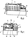
- Fig. 1
- in Vorderansicht eine erste Ausführungsform einer erfindungsgemäßen Einrichtung,
- Fig. 2
- eine Ansicht in Richtung des Pfeiles II in
Fig. 1 , - Fig. 3
- eine Ansicht in Richtung des Pfeiles III in
Fig. 1 , - Fig. 4
- eine Rückansicht der erfindungsgemäßen Einrichtung,
- Fig. 5
- eine Draufsicht auf die erfindungsgemäße Einrichtung,
- Fig. 6
- eine Unteransicht der erfindungsgemäßen Einrichtung,
- Fig. 7
- die erfindungsgemäße Einrichtung in perspektivischer Darstellung,
- Fig. 8
- eine Draufsicht auf eine zweite Ausführungsform einer erfindungsgemäßen Einrichtung,
- Fig. 9
- eine Ansicht in Richtung des Pfeiles IX in
Fig. 8 , - Fig. 10
- eine Ansicht in Richtung des Pfeiles X in
Fig. 8 , - Fig. 11
- eine Ansicht in Richtung des Pfeiles XI in
Fig. 8 , - Fig. 12
- die erfindungsgemäße Einrichtung gemäß
Fig. 8 in perspektivischer Darstellung. - Die Einrichtung gemäß den
Fig. 1 bis 7 hat ein Magazin 1, das bei dieser Ausführungsform als Rundmagazin ausgebildet ist. Dem Magazin 1 ist ein Transportsystem 2 zugeordnet, mit dem Probeflaschen 3 dem Magazin 1 entnommen sowie ihm zugeführt werden können. - Die Einrichtung befindet sich auf Milchsammelfahrzeugen, mit denen Milch von den Produktionsbetrieben abgeholt wird. Für die vom jeweiligen Produktionsbetrieb gelieferte Milch wird in die Probeflasche 3 eine Milchprobe eingefüllt, die später in einem Milchprüflabor geprüft wird.
- Die Einrichtung hat einen Träger 4, auf dem das Magazin 1 und das Transportsystem 2 angeordnet sind.
- Das Magazin 1 hat einen um eine senkrecht zur Trägeroberseite liegende Achse drehbar antreibbaren Boden 18 (
Fig. 5 und7 ). Der Boden 18 sitzt drehfest auf einer Achse 5. Sie ragt durch eine obere Trägerwand 6 nach oben. Unterhalb der Trägerwand 6 ist die Achse 5 mit einem entsprechenden Antrieb 7 verbunden (Fig. 6 ), mit dem die Achse 5 drehbar angetrieben wird. - Der Antrieb 7 ist in einer Aufnahme 8 untergebracht, die in Richtung auf das Magazin 1 durch die Trägerwand 6 begrenzt ist. An den Rand der Trägerwand 6 schließen Seitenwände 9 an, die die Aufnahme 8 seitlich begrenzen. Die Seitenwände 9 sind gleich hoch und schützen in der Einbaulage der Einrichtung den in der Aufnahme 8 untergebrachten Antrieb 7. Die Aufnahme 8 ist im Ausführungsbeispiel auf ihrer der Trägerwand 6 gegenüberliegenden Seite offen. Dadurch ist leichter Zugang zum Antrieb 7 möglich, falls er repariert, gewartet oder ausgetauscht werden muss. Die Aufnahme 8 kann selbstverständlich durch einen Boden geschlossen sein.
- In der Aufnahme 8 sind ferner eine Hubeinheit 39 zum Anheben der Probeflaschen 3 und ein Antriebsmotor 40 für eine (nicht dargestellte) Flaschendrehbox untergebracht. Die Probeflaschen 3 können somit gedreht werden, um an ihrer Außenseite angebrachte Barcodes mittels eines Barcode-Lesegerätes sicher erfassen zu können.
- Mit der vorzugsweise pneumatisch arbeitenden Hubeinheit 39 können die Probeflaschen 3 in eine Abfüllposition angehoben werden (vgl.
Fig 2 bis 4 und7 ). - Das Magazin 1 hat einen ringförmigen Aufnahmeraum 10 für die Probeflaschen 3. Er wird durch zwei koaxial zueinander liegende Ringwände 11, 12 in Radialrichtung begrenzt. Der Abstand zwischen den beiden Ringwänden 11, 12 entspricht im Wesentlichen dem Durchmesser der Probeflaschen 3, so dass diese im Aufnahmeraum 10 zuverlässig gegen Umkippen gesichert sind.
- Die äußere Ringwand 11 weist über den größten Teil ihres Umfanges parallel zur Drehachse 5 liegende und mit Abstand voneinander angeordnete Schlitze 13 auf, die mit Abstand vom oberen Rand 14 der Ringwand 11 enden und sich bis zum unteren Rand 15 der Ringwand 11 erstrecken. Die Schlitze 13 dienen der Material- und Gewichtsersparnis.
- Vorteilhaft sind die beiden Ringwände 12, 13 über Querstege 16 miteinander verbunden. Sie befinden sich am oberen Rand der beiden Ringwände 11, 12. Die Stege 16 sind vorteilhaft einstückig mit der inneren Ringwand 12 verbunden und erstrecken sich über den Aufnahmeraum 10 hinweg bis zur äußeren Ringwand 11. Das freie Ende 17 der Stege 16 ist rechtwinklig abgewinkelt und liegt an der Außenseite der äußeren Ringwand 11 an. Vorzugsweise ist das freie Stegende 17 fest mit der Ringwand 11 verbunden, beispielsweise verklebt.
- Die Ringwände 11, 12 sind in geeigneter Weise am Träger 4 gehalten.
- Beide Ringwände 11, 12 erstrecken sich senkrecht zum Boden 18, der den Aufnahmeraum 10 nach unten begrenzt. Die Probeflaschen 3 stehen im Aufnahmeraum 10 auf dem Boden 18.
- Das Magazin 1 hat einen Ein/Ausschleusebereich 19, über den die Probeflaschen 3 dem Magazin 1 übergeben bzw. ihm entnommen werden.
- Der Einschleusebereich 19a wird durch einen Verschlussbügel 20 vom Ausschleusebereich 19b getrennt (
Fig. 5 ). Mit dem Transportsystem 2 werden die Probeflaschen 3 dem Magazin 1 zugeführt. Außerdem dient das Transportsystem zum Transport der Probeflasche 3 zu einer Identifikations- und Abfüllposition 21 (Fig. 5 und7 ). - Zum Einschleusen der Probeflasche 3 in den Aufnahmeraum 10 des Magazins 1 ist ein vorteilhaft durch eine Kolben-Zylinder-Einheit gebildeter Antrieb 22 vorgesehen, der auf dem Träger 4 angeordnet ist und mit dem die Probeflasche 3 durch den Einschleusebereich 19a in den Aufnahmeraum 10 geschoben wird. Vorteilhaft wird die Probeflasche 3 im Bereich außerhalb des Magazins 1 in einen Schieber 24 eingesetzt, der mit einer Aufnahme 25 für die Probeflasche versehen ist und durch den Antrieb 22 etwa radial zum Magazin 1 so verschoben wird, dass die Probeflasche 3 in den Aufnahmeraum 10 des Magazins 1 gelangt. Anschließend wird der Schieber mittels des Antriebes 26 zurückgezogen. Auf diese Weise wird mit dem Schieber 24 jeweils eine Probeflasche 3 in den Aufnahmeraum 10 eingeschleust. Der Boden 18 des Magazins 1 wird jeweils so gedreht, dass der Einschleusebereich 19a zum Einschleusen der nächsten Probeflasche 3 frei ist. Der Boden 18 wird somit schrittweise gedreht.
- Gelangt die Probeflasche 3 in den Ausschleusebereich 19b, gelangt die in Drehrichtung jeweils vordere Probeflasche 3 in Kontakt mit dem Verschlussbügel 20, welcher den Ausschleusebereich 19b vom Einschleusebereich 19a trennt. Der Verschlussbügel 20 weist auf seiner dem Ausschleusebereich 19b zugewandten Seite eine gekrümmte oder auch schräg liegende Führungsfläche 23 auf (
Fig. 5 ), die dafür sorgt, dass die jeweils vordere Probeflasche 3 über diese Führungsfläche 23 aus dem Aufnahmeraum 10 ausgeschleust wird. - Die Führungsfläche 23 erstreckt sich etwa von der inneren Ringwand 12 aus bis an den Rand des Ausschleusebereiches 19b (
Fig. 5 ) und liegt, in Achsrichtung des Magazins 1 gesehen, stumpfwinklig zur Ringwand 12. Dadurch werden die Probeflaschen 3 zuverlässig schräg nach außen zum und durch den Ausschleusebereich 19b geleitet. - Der Schieber 24 ist mit einem Schieberantrieb 26 antriebsverbunden, mit dem er aus der in
Fig. 5 dargestellten Ausgangsposition mit der in die Aufnahme 25 eingesetzten Probeflasche 3 zur Barcode-Leseposition 21 transportiert werden kann, die sich vor dem Antrieb 22 befindet. Nach erfolgreicher Barcodeerfassung wird die Probeflasche 3 mittels der Hubeinheit 39 angehoben. In der angehobenen Position wird in die Probeflasche 3 eine (nicht dargestellte) Probeentnahmenadel eingestochen und eine repräsentative Milchprobe in die Probeflasche 3 injiziert. Anschließend wird die Probeflasche 3 abgesenkt. - Mit dem Antrieb 22 kann anschließend die gefüllte Probeflasche 3 in den Einschleusebereich 19a geschoben werden. Der Schieber 24 hat für den Durchtritt einer Kolbenstange des Antriebes 22 eine Bohrung 46 (
Fig. 4 ), durch die die Kolbenstange bewegt werden kann, um die Probeflasche 3 aus der Aufnahme 25 des Schiebers 24 in den Einschleusebereich 19a zu verschieben. Sobald die Probeflasche 3 in den Aufnahmeraum 10 eingeschleust ist, wird die Kolbenstange des Antriebes 22 aus dem Schieber 24 herausgezogen und anschließend der Schieber 24 mit dem Schieberantrieb 26 in die Ausgangslage gemäßFig. 4 zurückgefahren. - Die beiden Antriebe 22, 26 haben senkrecht zueinander liegende Antriebsrichtungen, die einen einfachen Transport der Probeflasche 3 ermöglichen.
- Wie aus den
Fig. 5 und7 hervorgeht, ist der Schieber 24 in der Übernahmeposition unmittelbar benachbart zum Ausschleusebereich 19b angeordnet. Die Führungsfläche 23 des Verschlussbügels 20 ist so ausgebildet, dass sie bis nahe an den Schieber 24 reicht. Vorteilhaft ist die Führungsfläche 23 so angeordnet, dass sie mit nur geringem Abstand an die Innenwand der Aufnahme 25 des Schiebers 24 anschließt. Dadurch kann die ausgeschleuste Probeflasche 3 zuverlässig in die Aufnahme 25 des Schiebers 24 verschoben werden. - Die Identifikations/Abfüllposition 21 dient zum Erfassen des auf der Probeflasche 3 seitlich angebrachten Barcodes oder Transponders. Da die Probeflasche 3 mittels des Antriebes 40 um ihre Achse gedreht wird, lässt sich der am Mantel der Probeflasche 3 angebrachte Barcode einfach in eine Lage bringen, in der er vom Barcodeleser erfasst werden kann.
- Die Probeflasche kann auch einen im Flaschenboden befindlichen Transponder aufweisen, der entsprechend erfasst wird.
- Die äußere Ringwand 11 ist im Ein/Ausschleusebereich 19 mit einer entsprechenden Öffnung versehen, so dass die Probeflaschen 3 zuverlässig ein- bzw. ausgeschleust werden können.
- Die innere Ringwand 12 kann beim Einschleusen der Probeflaschen 3 als Anschlag und Führung dienen, die dafür sorgt, dass die Probeflaschen 3 zuverlässig in den Aufnahmeraum 10 des Magazins 1 gelangen.
- Bei der beschriebenen Ausführungsform werden die Probeflaschen radial ein- und ausgeschleust. Grundsätzlich ist es möglich, den Ein/Ausschleusebereich 19 auch so auszubilden, dass die Probeflaschen axial in den Aufnahmeraum 10 eingeschleust sowie aus dem Aufnahmeraum 10 ausgeschleust werden können. In diesem Falle können anstelle der Schieber 24 beispielhaft Greifer vorgesehen sein, welche die Probeflaschen von oben in den Aufnahmeraum 10 einsetzen bzw. aus ihm herausheben. Auch in diesem Falle ist der Ein/Ausschleusebereich 19 so gestaltet, dass der Einschleusebereich 19a vom Ausschleusebereich 19b getrennt ist. Daher ist es wie bei der beschriebenen Ausführungsform möglich, gleichzeitig Probeflaschen einzuschleusen und auszuschleusen.
- Anstelle der beschriebenen Schieber können auch andere Aufnahmeeinrichtungen für die Probeflaschen 3 vorgesehen werden, beispielsweise Sternarme, deren Arme am radial äußeren Ende mit den entsprechenden Aufnahmen 25 für die Probeflaschen 3 versehen sind. Diese Sternarme sind dann so angeordnet, dass sie mit einem Arm dem Einschleusebereich 19a bzw. dem Ausschleusebereich 19b gegenüberliegen und nach Einschleusen bzw. Ausschleusen der jeweiligen Probeflasche so gedreht werden, dass der nächste Arm dem Einschleusebereich 19a bzw. dem Ausschleusebereich 19b gegenüberliegt.
- Die beschriebene Einrichtung zeichnet sich insbesondere durch ihre einfache konstruktive Gestaltung aus. Sie hat nur ein geringes Gewicht und benötigt nur geringen Platzbedarf im Sammelfahrzeug. Das Ein- und Ausschleusen der Probeflaschen kann vollautomatisch durchgeführt werden. Das Magazin 1 der Einrichtung ist so ausgebildet, dass es kompatibel zu vorhandenen, in Milchlaboren eingesetzten Automatisierungssystemen ist.
- Bei der Ausführungsform nach den
Fig. 8 bis 12 hat das Magazin 1 Rechteckform. Es ist auf dem Träger 4 angeordnet, der beispielhaft ebenfalls rechteckigen Umriss hat. Dieses Ausführungsbeispiel zeigt, dass statt einer runden Anordnung auch eine xy-Anordnung der Probeflaschen 3 möglich ist. - Das Magazin 1 hat parallel zueinander liegende Längsseiten 27, 28, die parallel zu den Längsseiten 29, 30 des Trägers 4 verlaufen. Die Längsseiten 27, 28 bzw. 29, 30 sind durch rechtwinklig zu ihnen verlaufende Schmalseiten 31, 32 bzw. 33, 34 miteinander verbunden.
- Im Unterschied zum Rundmagazin gemäß den
Fig. 1 bis 7 sind die Seitenwände 27, 28, 31, 32 des Magazins 1 niedriger als die Probeflaschen 3. Sie stehen daher über die Seitenwände 27, 28, 31, 32 des Magazins 1 vor. - Der Aufnahmeraum 10 des Magazins 1 ist im Unterschied zur vorigen Ausführungsform langgestreckt ausgebildet und besteht aus zwei parallel zueinander liegenden Aufnahmebereichen 10a, 10b, die durch eine Trennwand 35 über den größten Teil ihrer Länge voneinander getrennt sind. Die Trennwand 35 endet mit Abstand zu den Schmalseiten 31, 32 des Magazins 1 (
Fig. 8 ). Dadurch werden im Bereich dieser Schmalseiten 31, 32 Übergangsbereiche 36, 37 gebildet, über die die Probeflaschen 3 vom einen Abschnitt 10a in den anderen Abschnitt 10b des Aufnahmeraumes 10 gelangen können. - Im Übergangsbereich 37 befindet sich der Ein/Ausschleusebereich 19 für die Probeflaschen 3. Er hat den Einschleusebereich 19a (
Fig. 8 ), der durch ein Sperrelement 38 vom Ausschleusebereich 19b getrennt ist. Das Sperrelement 38 hat die Führungsfläche 23, über die die jeweilige Probeflasche 3 in den Ausschleusebereich 19b gebracht wird. Hier wird die Probeflasche 3 - im Unterschied zur vorigen Ausführungsform - axial dem Aufnahmeraum 10 entnommen. Das Sperrelement 38 sorgt dafür, dass die Probeflasche nicht aus dem Abschnitt 10b in den Abschnitt 10a des Aufnahmeraumes 8 gelangen kann. - Zum Ein- und Ausschleusen sind bei dieser Ausführungsform vier Antriebe 41 bis 44 vorgesehen, um nacheinander alle vorhandenen Probeflaschen 3 in die Barcodelese- und Abfüllposition zu transportieren. Die Antriebe 41 bis 44 sind vorteilhaft jeweils Kolben-Zylinder-Einheiten, von denen benachbarte Antriebe jeweils rechtwinklig zueinander liegen (
Fig. 8 ). Mit dem Antrieb 43 wird die untere Reihe der Probeflaschen 3 nach rechts in Richtung P verschoben. Dadurch wird ein Platz in der unteren Reihe frei, in den der Antrieb 42 die linke Probeflasche 3 der oberen Reihe schiebt. Mit dem Antrieb 41 kann dann die obere Reihe an Probeflaschen 3 entgegen Richtung P verschoben werden, wodurch ein in Verschieberichtung P vorderer Platz frei wird. In den frei gewordenen Platz in der oberen Reihe kann mit dem Antrieb 44 die letzte Probeflasche 3 in der unteren Reihe in die Abfüllposition am Einschleusebereich 19a verschoben werden. - In den Längsseiten 27, 27 und den Schmalseiten 31, 32 des Magazins 1 befinden sich Öffnungen für den Durchtritt von Kolbenstangen 45 bis 48 der Antriebe 41 bis 44 (
Fig. 8 ). - Anstelle der erwähnten Kolben-Zylinder-Einheiten können als Antriebe 41 bis 44 zum Transport der Probeflaschen 3 auch z.B. Transportbänder eingesetzt werden.
- Bei den beschriebenen Ausführungsformen werden die Probeflaschen 3 manuell in das Magazin 1 eingesetzt bzw. entnommen. Es ist auch denkbar, zum Befüllen oder Entnehmen der Probeflaschen 3 ein Wechselmagazin zu verwenden, das mit entsprechenden Öffnungen für die Antriebe 41 bis 44 aufweist. Außerdem ist mindestens eine Öffnung im Boden des Magazins für die Dreh- und/oder Hubeinrichtung an der Abfüllposition vorgesehen.
Claims (12)
- Einrichtung zum Sammeln von Milchprobenflaschen, mit wenigstens einem Magazin, das mindestens einen Aufnahmeraum für die Milchprobeflaschen aufweist, der mit wenigstens einem Einlass für die Milchprobeflaschen versehen ist,
dadurch gekennzeichnet, dass das Magazin (1) wenigstens einen gegen den Einlass (19a) gesperrten Auslass (19b) aufweist. - Einrichtung nach Anspruch 1,
dadurch gekennzeichnet, dass der Auslass (19b) mit einer Führung (23) zum Ausschleusen der Milchprobenflasche (3) aus dem Aufnahmeraum (10) versehen ist. - Einrichtung nach Anspruch 1 oder 2,
dadurch gekennzeichnet, dass der Aufnahmeraum (10) von zwei koaxialen Ringwänden (11, 12) begrenzt ist. - Einrichtung nach einem der Ansprüche 1 bis 3,
dadurch gekennzeichnet, dass der Auslass (19b) in der äußeren Ringwand (11) vorgesehen ist. - Einrichtung nach einem der Ansprüche 1 bis 4,
dadurch gekennzeichnet, dass der Einlass (19a) in der äußeren Ringwand (11) vorgesehen ist. - Einrichtung nach Anspruch 1 oder 2,
dadurch gekennzeichnet, dass der Aufnahmeraum (10) eckigen Umriss hat. - Einrichtung nach Anspruch 6,
dadurch gekennzeichnet, dass der Aufnahmeraum (10) von einem rechteckigen Rahmen (27, 28, 31, 32) begrenzt ist. - Einrichtung nach Anspruch 6 oder 7,
dadurch gekennzeichnet, dass im Aufnahmeraum (10) wenigstens eine Trennwand (35) vorgesehen ist, die den Aufnahmeraum (10) in wenigstens zwei Aufnahmeraum-Abschnitte (10a, 10b) unterteilt. - Einrichtung nach Anspruch 8,
dadurch gekennzeichnet, dass die Aufnahmeraum-Abschnitte (10a, 10b) an beiden Enden der Trennwand (35) miteinander verbunden sind. - Einrichtung nach einem der Ansprüche 1 bis 9,
dadurch gekennzeichnet, dass dem Magazin (1) wenigstens ein Transportsystem (2) zugeordnet ist, um die Milchprobeflaschen (3) zumindest in den Aufnahmeraum (10) einzuschleusen. - Einrichtung nach einem der Ansprüche 1 bis 10,
dadurch gekennzeichnet, dass das Transportsystem (2) einen Schieber (24) zum Einschleusen und einen Schieber (24) zum Abtransport der ausgeschleusten Milchprobeflaschen (3) aufweist. - Einrichtung nach einem der Ansprüche 1 bis 11,
dadurch gekennzeichnet, dass das Magazin (1) mit einem Antrieb (5, 7) zum Transport der Milchprobeflaschen (3) im Aufnahmeraum (10) versehen ist.
Applications Claiming Priority (1)
| Application Number | Priority Date | Filing Date | Title |
|---|---|---|---|
| DE102020001715.0A DE102020001715A1 (de) | 2020-03-11 | 2020-03-11 | Einrichtung zum Sammeln von Milchprobeflaschen |
Publications (2)
| Publication Number | Publication Date |
|---|---|
| EP3889078A1 true EP3889078A1 (de) | 2021-10-06 |
| EP3889078B1 EP3889078B1 (de) | 2024-12-11 |
Family
ID=74870559
Family Applications (1)
| Application Number | Title | Priority Date | Filing Date |
|---|---|---|---|
| EP21000067.5A Active EP3889078B1 (de) | 2020-03-11 | 2021-03-08 | Einrichtung zum sammeln von milchprobeflaschen |
Country Status (2)
| Country | Link |
|---|---|
| EP (1) | EP3889078B1 (de) |
| DE (1) | DE102020001715A1 (de) |
Citations (4)
| Publication number | Priority date | Publication date | Assignee | Title |
|---|---|---|---|---|
| GB2110624A (en) * | 1981-10-06 | 1983-06-22 | Kirin Brewery | Article holding apparatus of rotary type |
| FR2528015A1 (fr) * | 1982-06-02 | 1983-12-09 | Dubuit Mach | Carrousel de transfert a plateau rotatif, notamment pour machine a imprimer |
| US5029695A (en) * | 1990-04-03 | 1991-07-09 | S. C. Johnson & Son, Inc. | Improved starwheel |
| EP1105328B1 (de) * | 1999-05-19 | 2004-09-15 | Krones Ag | Vorrichtung zum einbringen und/oder ausbringen von behältern |
Family Cites Families (3)
| Publication number | Priority date | Publication date | Assignee | Title |
|---|---|---|---|---|
| DE10014087C2 (de) | 2000-03-22 | 2002-12-19 | Bartec Logistic Man Gmbh | Verfahren und Vorrichtung zur Identifikation, Befüllung und Aufbewahrung von Probeflaschen für Milch bei der Milchannahme mit einem Milchsammelwagen |
| DE102014100496B4 (de) | 2014-01-17 | 2016-05-12 | Khs Gmbh | Behälterbehandlungsmaschine sowie Verfahren zum Behandeln von Behältern |
| EP2993053B1 (de) | 2014-09-05 | 2019-09-04 | Sidel S.p.a. Con Socio Unico | Behälterhandhabungsmaschinen |
-
2020
- 2020-03-11 DE DE102020001715.0A patent/DE102020001715A1/de active Pending
-
2021
- 2021-03-08 EP EP21000067.5A patent/EP3889078B1/de active Active
Patent Citations (4)
| Publication number | Priority date | Publication date | Assignee | Title |
|---|---|---|---|---|
| GB2110624A (en) * | 1981-10-06 | 1983-06-22 | Kirin Brewery | Article holding apparatus of rotary type |
| FR2528015A1 (fr) * | 1982-06-02 | 1983-12-09 | Dubuit Mach | Carrousel de transfert a plateau rotatif, notamment pour machine a imprimer |
| US5029695A (en) * | 1990-04-03 | 1991-07-09 | S. C. Johnson & Son, Inc. | Improved starwheel |
| EP1105328B1 (de) * | 1999-05-19 | 2004-09-15 | Krones Ag | Vorrichtung zum einbringen und/oder ausbringen von behältern |
Also Published As
| Publication number | Publication date |
|---|---|
| DE102020001715A1 (de) | 2021-09-16 |
| EP3889078B1 (de) | 2024-12-11 |
Similar Documents
| Publication | Publication Date | Title |
|---|---|---|
| DE69315433T2 (de) | Vorrichtung zum transferieren, ruehren und entnehmen von blutprodukten aus proberoehrchen, die in einen gestell angeordnet sind | |
| DE3490484C2 (de) | ||
| DE602004013176T2 (de) | Vorrichtung zur durchführung von analysen in biologischen flüssigkeiten und damit verbundenes verfahren | |
| EP2207019B1 (de) | Wägegutträger für eine Waage | |
| EP2702386B1 (de) | Stanzvorrichtung mit greifeinheit | |
| EP3436832B1 (de) | Fördervorrichtung | |
| DE102019205930A1 (de) | Automatisches düsenreinigungs-inspektionsmanagementsystem | |
| DE102005039175A1 (de) | Vorrichtung und Verfahren zum Abtrennen von magnetischen Partikeln aus einer Flüssigkeit | |
| EP2674769B1 (de) | Vorrichtung und Verfahren zum Entnehmen von geprüften Halbleiterbauelementen | |
| EP1152244A2 (de) | Vorrichtung zur Positionierung von Objekten | |
| EP2141501B1 (de) | Vorrichtung zum Zuführen von Probenbehältern mit einer zu behandelnden Analysenprobe zu einem Behandlungsgerät | |
| WO2006119826A1 (de) | Vorrichtung zur handhabung und zuordnung mikrotomierter gewebeproben | |
| EP3932532B1 (de) | Mischapparat, mischanlage und verfahren zum mischen von substanzen in geschlossenen behältern | |
| EP3889078B1 (de) | Einrichtung zum sammeln von milchprobeflaschen | |
| DE202018104287U1 (de) | Mischapparat | |
| DE102019107893B4 (de) | Verfahren zum Betrieb eines Roboters, Werkzeugkopf für einen Roboter sowie Verarbeitungsstraße mit einem Roboter | |
| DE69416752T2 (de) | Vorrichtung zur Lagerung von zylindrischen Gegenständen, mit schneller Be- und Entladung | |
| EP1310303A1 (de) | Behälter für mehrere unterschiedliche bei der Durchführung eines Protokolls erforderlichen Reagenzien | |
| DE202019102011U1 (de) | Probenträger und Probenzuführvorrichtung | |
| DE102019109169A1 (de) | Probenträger und Probenzuführvorrichtung sowie Probenzuführverfahren | |
| DE19858158C2 (de) | Einer Transportvorrichtung zugeordnetes Lesesystem | |
| DE3128930C2 (de) | ||
| EP3528188B1 (de) | Vorrichtung zur aufnahme mehrerer behälter, system zur speicherung von sicherheitsdokumenten und verfahren zum disponieren von sicherheitsdokumenten | |
| DE102024116150A1 (de) | Kamera für eine Anlage zur Behandlung von Proben | |
| DE102024116148A1 (de) | Trägereinheit für den Transport eines Objekts |
Legal Events
| Date | Code | Title | Description |
|---|---|---|---|
| PUAI | Public reference made under article 153(3) epc to a published international application that has entered the european phase |
Free format text: ORIGINAL CODE: 0009012 |
|
| STAA | Information on the status of an ep patent application or granted ep patent |
Free format text: STATUS: THE APPLICATION HAS BEEN PUBLISHED |
|
| AK | Designated contracting states |
Kind code of ref document: A1 Designated state(s): AL AT BE BG CH CY CZ DE DK EE ES FI FR GB GR HR HU IE IS IT LI LT LU LV MC MK MT NL NO PL PT RO RS SE SI SK SM TR |
|
| STAA | Information on the status of an ep patent application or granted ep patent |
Free format text: STATUS: REQUEST FOR EXAMINATION WAS MADE |
|
| 17P | Request for examination filed |
Effective date: 20220406 |
|
| RBV | Designated contracting states (corrected) |
Designated state(s): AL AT BE BG CH CY CZ DE DK EE ES FI FR GB GR HR HU IE IS IT LI LT LU LV MC MK MT NL NO PL PT RO RS SE SI SK SM TR |
|
| STAA | Information on the status of an ep patent application or granted ep patent |
Free format text: STATUS: EXAMINATION IS IN PROGRESS |
|
| 17Q | First examination report despatched |
Effective date: 20230911 |
|
| GRAP | Despatch of communication of intention to grant a patent |
Free format text: ORIGINAL CODE: EPIDOSNIGR1 |
|
| STAA | Information on the status of an ep patent application or granted ep patent |
Free format text: STATUS: GRANT OF PATENT IS INTENDED |
|
| INTG | Intention to grant announced |
Effective date: 20240702 |
|
| RIN1 | Information on inventor provided before grant (corrected) |
Inventor name: LERACH, DIETER Inventor name: KAPPL, GERHARD ALOIS |
|
| GRAS | Grant fee paid |
Free format text: ORIGINAL CODE: EPIDOSNIGR3 |
|
| GRAA | (expected) grant |
Free format text: ORIGINAL CODE: 0009210 |
|
| STAA | Information on the status of an ep patent application or granted ep patent |
Free format text: STATUS: THE PATENT HAS BEEN GRANTED |
|
| AK | Designated contracting states |
Kind code of ref document: B1 Designated state(s): AL AT BE BG CH CY CZ DE DK EE ES FI FR GB GR HR HU IE IS IT LI LT LU LV MC MK MT NL NO PL PT RO RS SE SI SK SM TR |
|
| REG | Reference to a national code |
Ref country code: GB Ref legal event code: FG4D Free format text: NOT ENGLISH |
|
| REG | Reference to a national code |
Ref country code: CH Ref legal event code: EP |
|
| REG | Reference to a national code |
Ref country code: DE Ref legal event code: R096 Ref document number: 502021006053 Country of ref document: DE |
|
| REG | Reference to a national code |
Ref country code: IE Ref legal event code: FG4D Free format text: LANGUAGE OF EP DOCUMENT: GERMAN |
|
| REG | Reference to a national code |
Ref country code: LT Ref legal event code: MG9D |
|
| PG25 | Lapsed in a contracting state [announced via postgrant information from national office to epo] |
Ref country code: HR Free format text: LAPSE BECAUSE OF FAILURE TO SUBMIT A TRANSLATION OF THE DESCRIPTION OR TO PAY THE FEE WITHIN THE PRESCRIBED TIME-LIMIT Effective date: 20241211 |
|
| PG25 | Lapsed in a contracting state [announced via postgrant information from national office to epo] |
Ref country code: FI Free format text: LAPSE BECAUSE OF FAILURE TO SUBMIT A TRANSLATION OF THE DESCRIPTION OR TO PAY THE FEE WITHIN THE PRESCRIBED TIME-LIMIT Effective date: 20241211 |
|
| PG25 | Lapsed in a contracting state [announced via postgrant information from national office to epo] |
Ref country code: BG Free format text: LAPSE BECAUSE OF FAILURE TO SUBMIT A TRANSLATION OF THE DESCRIPTION OR TO PAY THE FEE WITHIN THE PRESCRIBED TIME-LIMIT Effective date: 20241211 |
|
| REG | Reference to a national code |
Ref country code: NL Ref legal event code: MP Effective date: 20241211 |
|
| PG25 | Lapsed in a contracting state [announced via postgrant information from national office to epo] |
Ref country code: ES Free format text: LAPSE BECAUSE OF FAILURE TO SUBMIT A TRANSLATION OF THE DESCRIPTION OR TO PAY THE FEE WITHIN THE PRESCRIBED TIME-LIMIT Effective date: 20241211 |
|
| PG25 | Lapsed in a contracting state [announced via postgrant information from national office to epo] |
Ref country code: NO Free format text: LAPSE BECAUSE OF FAILURE TO SUBMIT A TRANSLATION OF THE DESCRIPTION OR TO PAY THE FEE WITHIN THE PRESCRIBED TIME-LIMIT Effective date: 20250311 |
|
| PG25 | Lapsed in a contracting state [announced via postgrant information from national office to epo] |
Ref country code: LV Free format text: LAPSE BECAUSE OF FAILURE TO SUBMIT A TRANSLATION OF THE DESCRIPTION OR TO PAY THE FEE WITHIN THE PRESCRIBED TIME-LIMIT Effective date: 20241211 Ref country code: GR Free format text: LAPSE BECAUSE OF FAILURE TO SUBMIT A TRANSLATION OF THE DESCRIPTION OR TO PAY THE FEE WITHIN THE PRESCRIBED TIME-LIMIT Effective date: 20250312 |
|
| PG25 | Lapsed in a contracting state [announced via postgrant information from national office to epo] |
Ref country code: RS Free format text: LAPSE BECAUSE OF FAILURE TO SUBMIT A TRANSLATION OF THE DESCRIPTION OR TO PAY THE FEE WITHIN THE PRESCRIBED TIME-LIMIT Effective date: 20250311 |
|
| PG25 | Lapsed in a contracting state [announced via postgrant information from national office to epo] |
Ref country code: NL Free format text: LAPSE BECAUSE OF FAILURE TO SUBMIT A TRANSLATION OF THE DESCRIPTION OR TO PAY THE FEE WITHIN THE PRESCRIBED TIME-LIMIT Effective date: 20241211 |
|
| PG25 | Lapsed in a contracting state [announced via postgrant information from national office to epo] |
Ref country code: SM Free format text: LAPSE BECAUSE OF FAILURE TO SUBMIT A TRANSLATION OF THE DESCRIPTION OR TO PAY THE FEE WITHIN THE PRESCRIBED TIME-LIMIT Effective date: 20241211 |
|
| PG25 | Lapsed in a contracting state [announced via postgrant information from national office to epo] |
Ref country code: PL Free format text: LAPSE BECAUSE OF FAILURE TO SUBMIT A TRANSLATION OF THE DESCRIPTION OR TO PAY THE FEE WITHIN THE PRESCRIBED TIME-LIMIT Effective date: 20241211 |
|
| PG25 | Lapsed in a contracting state [announced via postgrant information from national office to epo] |
Ref country code: IS Free format text: LAPSE BECAUSE OF FAILURE TO SUBMIT A TRANSLATION OF THE DESCRIPTION OR TO PAY THE FEE WITHIN THE PRESCRIBED TIME-LIMIT Effective date: 20250411 |
|
| PG25 | Lapsed in a contracting state [announced via postgrant information from national office to epo] |
Ref country code: PT Free format text: LAPSE BECAUSE OF FAILURE TO SUBMIT A TRANSLATION OF THE DESCRIPTION OR TO PAY THE FEE WITHIN THE PRESCRIBED TIME-LIMIT Effective date: 20250411 |
|
| PG25 | Lapsed in a contracting state [announced via postgrant information from national office to epo] |
Ref country code: EE Free format text: LAPSE BECAUSE OF FAILURE TO SUBMIT A TRANSLATION OF THE DESCRIPTION OR TO PAY THE FEE WITHIN THE PRESCRIBED TIME-LIMIT Effective date: 20241211 |
|
| PG25 | Lapsed in a contracting state [announced via postgrant information from national office to epo] |
Ref country code: RO Free format text: LAPSE BECAUSE OF FAILURE TO SUBMIT A TRANSLATION OF THE DESCRIPTION OR TO PAY THE FEE WITHIN THE PRESCRIBED TIME-LIMIT Effective date: 20241211 |
|
| PG25 | Lapsed in a contracting state [announced via postgrant information from national office to epo] |
Ref country code: SK Free format text: LAPSE BECAUSE OF FAILURE TO SUBMIT A TRANSLATION OF THE DESCRIPTION OR TO PAY THE FEE WITHIN THE PRESCRIBED TIME-LIMIT Effective date: 20241211 |
|
| PG25 | Lapsed in a contracting state [announced via postgrant information from national office to epo] |
Ref country code: CZ Free format text: LAPSE BECAUSE OF FAILURE TO SUBMIT A TRANSLATION OF THE DESCRIPTION OR TO PAY THE FEE WITHIN THE PRESCRIBED TIME-LIMIT Effective date: 20241211 |
|
| PG25 | Lapsed in a contracting state [announced via postgrant information from national office to epo] |
Ref country code: IT Free format text: LAPSE BECAUSE OF FAILURE TO SUBMIT A TRANSLATION OF THE DESCRIPTION OR TO PAY THE FEE WITHIN THE PRESCRIBED TIME-LIMIT Effective date: 20241211 |
|
| PG25 | Lapsed in a contracting state [announced via postgrant information from national office to epo] |
Ref country code: SE Free format text: LAPSE BECAUSE OF FAILURE TO SUBMIT A TRANSLATION OF THE DESCRIPTION OR TO PAY THE FEE WITHIN THE PRESCRIBED TIME-LIMIT Effective date: 20241211 |
|
| REG | Reference to a national code |
Ref country code: DE Ref legal event code: R097 Ref document number: 502021006053 Country of ref document: DE |
|
| PG25 | Lapsed in a contracting state [announced via postgrant information from national office to epo] |
Ref country code: DK Free format text: LAPSE BECAUSE OF FAILURE TO SUBMIT A TRANSLATION OF THE DESCRIPTION OR TO PAY THE FEE WITHIN THE PRESCRIBED TIME-LIMIT Effective date: 20241211 |
|
| PG25 | Lapsed in a contracting state [announced via postgrant information from national office to epo] |
Ref country code: MC Free format text: LAPSE BECAUSE OF FAILURE TO SUBMIT A TRANSLATION OF THE DESCRIPTION OR TO PAY THE FEE WITHIN THE PRESCRIBED TIME-LIMIT Effective date: 20241211 |
|
| PLBE | No opposition filed within time limit |
Free format text: ORIGINAL CODE: 0009261 |
|
| STAA | Information on the status of an ep patent application or granted ep patent |
Free format text: STATUS: NO OPPOSITION FILED WITHIN TIME LIMIT |
|
| REG | Reference to a national code |
Ref country code: CH Ref legal event code: L10 Free format text: ST27 STATUS EVENT CODE: U-0-0-L10-L00 (AS PROVIDED BY THE NATIONAL OFFICE) Effective date: 20251022 |
|
| REG | Reference to a national code |
Ref country code: CH Ref legal event code: H13 Free format text: ST27 STATUS EVENT CODE: U-0-0-H10-H13 (AS PROVIDED BY THE NATIONAL OFFICE) Effective date: 20251023 |
|
| PG25 | Lapsed in a contracting state [announced via postgrant information from national office to epo] |
Ref country code: LU Free format text: LAPSE BECAUSE OF NON-PAYMENT OF DUE FEES Effective date: 20250308 |
|
| 26N | No opposition filed |
Effective date: 20250912 |
|
| GBPC | Gb: european patent ceased through non-payment of renewal fee |
Effective date: 20250311 |
|
| REG | Reference to a national code |
Ref country code: BE Ref legal event code: MM Effective date: 20250331 |
|
| PG25 | Lapsed in a contracting state [announced via postgrant information from national office to epo] |
Ref country code: GB Free format text: LAPSE BECAUSE OF NON-PAYMENT OF DUE FEES Effective date: 20250311 |
|
| PG25 | Lapsed in a contracting state [announced via postgrant information from national office to epo] |
Ref country code: FR Free format text: LAPSE BECAUSE OF NON-PAYMENT OF DUE FEES Effective date: 20250331 |
|
| REG | Reference to a national code |
Ref country code: AT Ref legal event code: PC Ref document number: 1750252 Country of ref document: AT Kind code of ref document: T Owner name: ULTRAKUST GMBH, DE Effective date: 20251117 |
|
| PG25 | Lapsed in a contracting state [announced via postgrant information from national office to epo] |
Ref country code: BE Free format text: LAPSE BECAUSE OF NON-PAYMENT OF DUE FEES Effective date: 20250331 |
|
| PG25 | Lapsed in a contracting state [announced via postgrant information from national office to epo] |
Ref country code: CH Free format text: LAPSE BECAUSE OF NON-PAYMENT OF DUE FEES Effective date: 20250331 |
|
| PG25 | Lapsed in a contracting state [announced via postgrant information from national office to epo] |
Ref country code: IE Free format text: LAPSE BECAUSE OF NON-PAYMENT OF DUE FEES Effective date: 20250308 |
|
| PGFP | Annual fee paid to national office [announced via postgrant information from national office to epo] |
Ref country code: AT Payment date: 20260320 Year of fee payment: 6 |
|
| PG25 | Lapsed in a contracting state [announced via postgrant information from national office to epo] |
Ref country code: CY Free format text: LAPSE BECAUSE OF FAILURE TO SUBMIT A TRANSLATION OF THE DESCRIPTION OR TO PAY THE FEE WITHIN THE PRESCRIBED TIME-LIMIT Effective date: 20241211 |
|
| PG25 | Lapsed in a contracting state [announced via postgrant information from national office to epo] |
Ref country code: LT Free format text: LAPSE BECAUSE OF FAILURE TO SUBMIT A TRANSLATION OF THE DESCRIPTION OR TO PAY THE FEE WITHIN THE PRESCRIBED TIME-LIMIT Effective date: 20241211 |
|
| PG25 | Lapsed in a contracting state [announced via postgrant information from national office to epo] |
Ref country code: TR Free format text: LAPSE BECAUSE OF FAILURE TO SUBMIT A TRANSLATION OF THE DESCRIPTION OR TO PAY THE FEE WITHIN THE PRESCRIBED TIME-LIMIT Effective date: 20241211 |
|
| PGFP | Annual fee paid to national office [announced via postgrant information from national office to epo] |
Ref country code: DE Payment date: 20260527 Year of fee payment: 6 |