EP3889058A1 - Tubular structural profile and construction system, produced by cutting and folding a semi-rigid and foldable sheet, with 4 substantially orthoginal layers joined at fold lines and internal diagonal layers joining two opposing fold lines, and at least one tongue which coincides with at least one slot - Google Patents
Tubular structural profile and construction system, produced by cutting and folding a semi-rigid and foldable sheet, with 4 substantially orthoginal layers joined at fold lines and internal diagonal layers joining two opposing fold lines, and at least one tongue which coincides with at least one slot Download PDFInfo
- Publication number
- EP3889058A1 EP3889058A1 EP18941711.6A EP18941711A EP3889058A1 EP 3889058 A1 EP3889058 A1 EP 3889058A1 EP 18941711 A EP18941711 A EP 18941711A EP 3889058 A1 EP3889058 A1 EP 3889058A1
- Authority
- EP
- European Patent Office
- Prior art keywords
- layers
- fold lines
- folding
- profile
- external
- Prior art date
- Legal status (The legal status is an assumption and is not a legal conclusion. Google has not performed a legal analysis and makes no representation as to the accuracy of the status listed.)
- Granted
Links
Images




Classifications
-
- A—HUMAN NECESSITIES
- A47—FURNITURE; DOMESTIC ARTICLES OR APPLIANCES; COFFEE MILLS; SPICE MILLS; SUCTION CLEANERS IN GENERAL
- A47F—SPECIAL FURNITURE, FITTINGS, OR ACCESSORIES FOR SHOPS, STOREHOUSES, BARS, RESTAURANTS OR THE LIKE; PAYING COUNTERS
- A47F5/00—Show stands, hangers, or shelves characterised by their constructional features
- A47F5/10—Adjustable or foldable or dismountable display stands
- A47F5/13—Adjustable or foldable or dismountable display stands made of tubes or wire
-
- B—PERFORMING OPERATIONS; TRANSPORTING
- B65—CONVEYING; PACKING; STORING; HANDLING THIN OR FILAMENTARY MATERIAL
- B65D—CONTAINERS FOR STORAGE OR TRANSPORT OF ARTICLES OR MATERIALS, e.g. BAGS, BARRELS, BOTTLES, BOXES, CANS, CARTONS, CRATES, DRUMS, JARS, TANKS, HOPPERS, FORWARDING CONTAINERS; ACCESSORIES, CLOSURES, OR FITTINGS THEREFOR; PACKAGING ELEMENTS; PACKAGES
- B65D5/00—Rigid or semi-rigid containers of polygonal cross-section, e.g. boxes, cartons or trays, formed by folding or erecting one or more blanks made of paper
- B65D5/42—Details of containers or of foldable or erectable container blanks
- B65D5/44—Integral, inserted or attached portions forming internal or external fittings
- B65D5/441—Reinforcements
- B65D5/445—Reinforcements formed separately from the container
-
- A—HUMAN NECESSITIES
- A47—FURNITURE; DOMESTIC ARTICLES OR APPLIANCES; COFFEE MILLS; SPICE MILLS; SUCTION CLEANERS IN GENERAL
- A47B—TABLES; DESKS; OFFICE FURNITURE; CABINETS; DRAWERS; GENERAL DETAILS OF FURNITURE
- A47B55/00—Cabinets, racks or shelf units, having essential features of rigid construction
- A47B55/06—Cabinets, racks or shelf units, having essential features of rigid construction made of cardboard, paper, or the like
-
- A—HUMAN NECESSITIES
- A47—FURNITURE; DOMESTIC ARTICLES OR APPLIANCES; COFFEE MILLS; SPICE MILLS; SUCTION CLEANERS IN GENERAL
- A47B—TABLES; DESKS; OFFICE FURNITURE; CABINETS; DRAWERS; GENERAL DETAILS OF FURNITURE
- A47B96/00—Details of cabinets, racks or shelf units not covered by a single one of groups A47B43/00 - A47B95/00; General details of furniture
- A47B96/14—Bars, uprights, struts, or like supports, for cabinets, brackets, or the like
- A47B96/1433—Hollow members
-
- A—HUMAN NECESSITIES
- A47—FURNITURE; DOMESTIC ARTICLES OR APPLIANCES; COFFEE MILLS; SPICE MILLS; SUCTION CLEANERS IN GENERAL
- A47F—SPECIAL FURNITURE, FITTINGS, OR ACCESSORIES FOR SHOPS, STOREHOUSES, BARS, RESTAURANTS OR THE LIKE; PAYING COUNTERS
- A47F5/00—Show stands, hangers, or shelves characterised by their constructional features
- A47F5/10—Adjustable or foldable or dismountable display stands
- A47F5/11—Adjustable or foldable or dismountable display stands made of cardboard, paper or the like
-
- A—HUMAN NECESSITIES
- A47—FURNITURE; DOMESTIC ARTICLES OR APPLIANCES; COFFEE MILLS; SPICE MILLS; SUCTION CLEANERS IN GENERAL
- A47F—SPECIAL FURNITURE, FITTINGS, OR ACCESSORIES FOR SHOPS, STOREHOUSES, BARS, RESTAURANTS OR THE LIKE; PAYING COUNTERS
- A47F5/00—Show stands, hangers, or shelves characterised by their constructional features
- A47F5/10—Adjustable or foldable or dismountable display stands
- A47F5/11—Adjustable or foldable or dismountable display stands made of cardboard, paper or the like
- A47F5/112—Adjustable or foldable or dismountable display stands made of cardboard, paper or the like hand-folded from sheet material
-
- B—PERFORMING OPERATIONS; TRANSPORTING
- B65—CONVEYING; PACKING; STORING; HANDLING THIN OR FILAMENTARY MATERIAL
- B65D—CONTAINERS FOR STORAGE OR TRANSPORT OF ARTICLES OR MATERIALS, e.g. BAGS, BARRELS, BOTTLES, BOXES, CANS, CARTONS, CRATES, DRUMS, JARS, TANKS, HOPPERS, FORWARDING CONTAINERS; ACCESSORIES, CLOSURES, OR FITTINGS THEREFOR; PACKAGING ELEMENTS; PACKAGES
- B65D19/00—Pallets or like platforms, with or without side walls, for supporting loads to be lifted or lowered
- B65D19/02—Rigid pallets with side walls, e.g. box pallets
- B65D19/06—Rigid pallets with side walls, e.g. box pallets with bodies formed by uniting or interconnecting two or more components
- B65D19/20—Rigid pallets with side walls, e.g. box pallets with bodies formed by uniting or interconnecting two or more components made wholly or mainly of paper
-
- B—PERFORMING OPERATIONS; TRANSPORTING
- B65—CONVEYING; PACKING; STORING; HANDLING THIN OR FILAMENTARY MATERIAL
- B65D—CONTAINERS FOR STORAGE OR TRANSPORT OF ARTICLES OR MATERIALS, e.g. BAGS, BARRELS, BOTTLES, BOXES, CANS, CARTONS, CRATES, DRUMS, JARS, TANKS, HOPPERS, FORWARDING CONTAINERS; ACCESSORIES, CLOSURES, OR FITTINGS THEREFOR; PACKAGING ELEMENTS; PACKAGES
- B65D19/00—Pallets or like platforms, with or without side walls, for supporting loads to be lifted or lowered
- B65D19/38—Details or accessories
- B65D19/385—Frames, corner posts or pallet converters, e.g. for facilitating stacking of charged pallets
-
- E—FIXED CONSTRUCTIONS
- E04—BUILDING
- E04C—STRUCTURAL ELEMENTS; BUILDING MATERIALS
- E04C3/00—Structural elongated elements designed for load-supporting
- E04C3/02—Joists; Girders, trusses, or trusslike structures, e.g. prefabricated; Lintels; Transoms; Braces
- E04C3/04—Joists; Girders, trusses, or trusslike structures, e.g. prefabricated; Lintels; Transoms; Braces of metal
- E04C3/06—Joists; Girders, trusses, or trusslike structures, e.g. prefabricated; Lintels; Transoms; Braces of metal with substantially solid, i.e. unapertured, web
- E04C3/07—Joists; Girders, trusses, or trusslike structures, e.g. prefabricated; Lintels; Transoms; Braces of metal with substantially solid, i.e. unapertured, web at least partly of bent or otherwise deformed strip- or sheet-like material
-
- A—HUMAN NECESSITIES
- A47—FURNITURE; DOMESTIC ARTICLES OR APPLIANCES; COFFEE MILLS; SPICE MILLS; SUCTION CLEANERS IN GENERAL
- A47B—TABLES; DESKS; OFFICE FURNITURE; CABINETS; DRAWERS; GENERAL DETAILS OF FURNITURE
- A47B2220/00—General furniture construction, e.g. fittings
- A47B2220/008—General furniture construction, e.g. fittings characterised by materials
- A47B2220/0083—Furniture made of sheet material
-
- B—PERFORMING OPERATIONS; TRANSPORTING
- B65—CONVEYING; PACKING; STORING; HANDLING THIN OR FILAMENTARY MATERIAL
- B65D—CONTAINERS FOR STORAGE OR TRANSPORT OF ARTICLES OR MATERIALS, e.g. BAGS, BARRELS, BOTTLES, BOXES, CANS, CARTONS, CRATES, DRUMS, JARS, TANKS, HOPPERS, FORWARDING CONTAINERS; ACCESSORIES, CLOSURES, OR FITTINGS THEREFOR; PACKAGING ELEMENTS; PACKAGES
- B65D2519/00—Pallets or like platforms, with or without side walls, for supporting loads to be lifted or lowered
- B65D2519/00004—Details relating to pallets
- B65D2519/00009—Materials
- B65D2519/00223—Materials for the corner elements or corner frames
- B65D2519/00228—Paper
-
- B—PERFORMING OPERATIONS; TRANSPORTING
- B65—CONVEYING; PACKING; STORING; HANDLING THIN OR FILAMENTARY MATERIAL
- B65D—CONTAINERS FOR STORAGE OR TRANSPORT OF ARTICLES OR MATERIALS, e.g. BAGS, BARRELS, BOTTLES, BOXES, CANS, CARTONS, CRATES, DRUMS, JARS, TANKS, HOPPERS, FORWARDING CONTAINERS; ACCESSORIES, CLOSURES, OR FITTINGS THEREFOR; PACKAGING ELEMENTS; PACKAGES
- B65D2519/00—Pallets or like platforms, with or without side walls, for supporting loads to be lifted or lowered
- B65D2519/00004—Details relating to pallets
- B65D2519/00258—Overall construction
- B65D2519/00398—Overall construction reinforcements
- B65D2519/00402—Integral, e.g. ribs
-
- B—PERFORMING OPERATIONS; TRANSPORTING
- B65—CONVEYING; PACKING; STORING; HANDLING THIN OR FILAMENTARY MATERIAL
- B65D—CONTAINERS FOR STORAGE OR TRANSPORT OF ARTICLES OR MATERIALS, e.g. BAGS, BARRELS, BOTTLES, BOXES, CANS, CARTONS, CRATES, DRUMS, JARS, TANKS, HOPPERS, FORWARDING CONTAINERS; ACCESSORIES, CLOSURES, OR FITTINGS THEREFOR; PACKAGING ELEMENTS; PACKAGES
- B65D2519/00—Pallets or like platforms, with or without side walls, for supporting loads to be lifted or lowered
- B65D2519/00004—Details relating to pallets
- B65D2519/00736—Details
- B65D2519/0081—Elements or devices for locating articles
-
- E—FIXED CONSTRUCTIONS
- E04—BUILDING
- E04C—STRUCTURAL ELEMENTS; BUILDING MATERIALS
- E04C3/00—Structural elongated elements designed for load-supporting
- E04C3/02—Joists; Girders, trusses, or trusslike structures, e.g. prefabricated; Lintels; Transoms; Braces
- E04C3/04—Joists; Girders, trusses, or trusslike structures, e.g. prefabricated; Lintels; Transoms; Braces of metal
- E04C2003/0404—Joists; Girders, trusses, or trusslike structures, e.g. prefabricated; Lintels; Transoms; Braces of metal beams, girders, or joists characterised by cross-sectional aspects
- E04C2003/0408—Joists; Girders, trusses, or trusslike structures, e.g. prefabricated; Lintels; Transoms; Braces of metal beams, girders, or joists characterised by cross-sectional aspects characterised by assembly or the cross-section
- E04C2003/0421—Joists; Girders, trusses, or trusslike structures, e.g. prefabricated; Lintels; Transoms; Braces of metal beams, girders, or joists characterised by cross-sectional aspects characterised by assembly or the cross-section comprising one single unitary part
-
- E—FIXED CONSTRUCTIONS
- E04—BUILDING
- E04C—STRUCTURAL ELEMENTS; BUILDING MATERIALS
- E04C3/00—Structural elongated elements designed for load-supporting
- E04C3/02—Joists; Girders, trusses, or trusslike structures, e.g. prefabricated; Lintels; Transoms; Braces
- E04C3/04—Joists; Girders, trusses, or trusslike structures, e.g. prefabricated; Lintels; Transoms; Braces of metal
- E04C2003/0404—Joists; Girders, trusses, or trusslike structures, e.g. prefabricated; Lintels; Transoms; Braces of metal beams, girders, or joists characterised by cross-sectional aspects
- E04C2003/0426—Joists; Girders, trusses, or trusslike structures, e.g. prefabricated; Lintels; Transoms; Braces of metal beams, girders, or joists characterised by cross-sectional aspects characterised by material distribution in cross section
- E04C2003/043—Joists; Girders, trusses, or trusslike structures, e.g. prefabricated; Lintels; Transoms; Braces of metal beams, girders, or joists characterised by cross-sectional aspects characterised by material distribution in cross section the hollow cross-section comprising at least one enclosed cavity
-
- E—FIXED CONSTRUCTIONS
- E04—BUILDING
- E04C—STRUCTURAL ELEMENTS; BUILDING MATERIALS
- E04C3/00—Structural elongated elements designed for load-supporting
- E04C3/02—Joists; Girders, trusses, or trusslike structures, e.g. prefabricated; Lintels; Transoms; Braces
- E04C3/04—Joists; Girders, trusses, or trusslike structures, e.g. prefabricated; Lintels; Transoms; Braces of metal
- E04C2003/0404—Joists; Girders, trusses, or trusslike structures, e.g. prefabricated; Lintels; Transoms; Braces of metal beams, girders, or joists characterised by cross-sectional aspects
- E04C2003/0443—Joists; Girders, trusses, or trusslike structures, e.g. prefabricated; Lintels; Transoms; Braces of metal beams, girders, or joists characterised by cross-sectional aspects characterised by substantial shape of the cross-section
- E04C2003/0465—Joists; Girders, trusses, or trusslike structures, e.g. prefabricated; Lintels; Transoms; Braces of metal beams, girders, or joists characterised by cross-sectional aspects characterised by substantial shape of the cross-section square- or rectangular-shaped
Definitions
- the technical problem that the present invention solves refers to achieving a structural profile and a composite structure or construction system using this profile, made of semi-rigid and foldable material, as is the particular case of cardboard, in order to create by means of folding of a sheet, a rigid and lightweight structure, usable in various fields of application, especially in the manufacture of composite structures for the industry of packaging, furniture, the display of consumer products for sale, for example.
- a tubular structural profile which is manufactured starting from the folding and cutting of a sheet of semi-rigid and foldable material, with high rigidity against bending, compression and torsion, the external contour of which comprises 4 substantially orthogonal layers joined at fold lines and an internal section, located diagonally joining two opposing fold lines, and a construction system or composite structure made of the aforementioned profile, wherein the sheet of semi-rigid material has 6 rectangular, adjacent and parallel sections, separated from each other by fold lines, wherein the two central sections correspond to two first external layers (1 and 2), separated by a first fold line (10), followed towards the ends of two second external layers (3 and 4), separated from the first external layers by two second fold lines (11 and 12), and next, in a symmetrical manner two internal diagonal layers (5 and 6), separated from the second external layers by two third fold lines (13 and 14); each fold is performed in a single rotation direction, wherein the folding of the sheet on the third fold lines is performed at a rotation angle greater than 90° in order to position the two diagonal layers, in order to then
- the tubular structural profile can have at least one break in the second external layers (3 and 4) and in the two internal diagonal layers (5 and 6), in a symmetrical manner, which permit the creation of an engaging area (15) for transverse structural profiles which make up a set of elements of the construction system or composite structure.
- US2011271623 (A1 ) discloses a construction element for buildings having a hollow body, which extends along a longitudinal axis and has a substantially rectangular transverse cross section, wherein the corners can be rounded, and at least one first and at least one second strut element extending between diagonally opposing borders in the hollow body.
- the strut elements can absorb compressive forces, but not tensile forces.
- Different prefabricated elements can be positioned in the place of the strut elements.
- the innovation although it contains elements in common with the present invention, does not envisage the elements necessary for an assembly of the structural element starting from a sheet of material, but rather requires a closed tube as the base material, plus the strut elements.
- the document FR2951705 (A1 ) discloses a pallet spar which is made starting from folding a rectangular sheet of cardboard which comprises parallel fold lines which divide the sheet into 8 rectangular sectors, in order to obtain a solid part.
- the innovation comprises elements in common with the present invention, such as a diagonal section and faces and 4 substantially orthogonal layers, but the manner of folding thereof is different and does not envisage other elements necessary for closing the profile, such as the tongues and slots wherein these are inserted.
- US4563377 discloses a high-strength tubular beam of corrugated cardboard, for example, for constructing disposable load-carrying platforms, comprising a single cardboard sheet folded back several times on itself to form a rectangular or isosceles trapezium external cross section, divided into two adjacent rectangular or trapezium cross sections, each comprising two mutually inverted triangular cross sections having a diagonal in common.
- the innovation has elements in common with the present invention, however, it differs in the form of folding and layout of the sheet thereof, in addition to envisaging diagonal segments which are simple and not formed by two layers as in the present invention, and additionally, it does not envisage closing means for the profile, which can only achieve closing and structural strength by being adhered to an external element by the open face thereof.
- the document US4333622 (A ) discloses a knockdown spacer for bookshelves and the like which is made from a rectangular sheet of material, folded at spaced intervals to fold into an open ended box-like shape with internal diagonal walls, wherein the external walls of the box wrap around the diagonal walls and one end of the sheet has a flap which overlaps one of the walls and is secured by means of releasable fastening elements.
- the innovation has elements in common with the present invention, however, it differs in the form of folding and layout of the sheet thereof, in addition to envisaging, and in an additional manner, it does not envisage closing means created in the sheet of material, but rather requires external elements.
- the present invention is applied in various fields of application, especially in the manufacture of composite structures for the industry of packaging, furniture, the display of consumer products for sale, for example.
- a tubular structural profile which is manufactured starting from the folding and cutting of a sheet of semi-rigid and foldable material, with high rigidity against bending, compression and torsion, the external contour of which comprises 4 substantially orthogonal layers joined at fold lines and an internal section, located diagonally joining two opposing fold lines, and a construction system or composite structure made of the aforementioned profile, wherein the sheet of semi-rigid material has 6 rectangular, adjacent and parallel sections, separated from each other by fold lines, wherein the two central sections correspond to two first external layers (1 and 2), separated by a first fold line (10), followed towards the ends of two second external layers (3 and 4), separated from the first external layers by two second fold lines (11 and 12), and next, in a symmetrical manner two internal diagonal layers (5 and 6), separated from the second external layers by two third fold lines (13 and 14); each fold is performed in a single rotation direction, wherein the folding of the sheet on the third fold lines is performed at a rotation angle greater than 90° in order to position the two diagonal layers, in order to then
- the tubular structural profile can have at least one break in the second external layers (3 and 4) and in the two internal diagonal layers (5 and 6), in a symmetrical manner, which permit the creation of an engaging area (15) for transverse structural profiles which make up a set of elements of the construction system or composite structure.
- the first fold line (10) of the tubular profile can be divided into two parallel rectilinear trajectories, separated from each other by a distance similar to twice the thickness of the material of the sheet, so that during the folding a surface comprised between both trajectories comes into contact in a more integral manner with the external borders of the two internal diagonal layers (5 and 6), such that it produces an increase in the strength and structural stability of the profile.
- the width of the two internal diagonal layers (5 and 6) of at least one of the tubular structural profiles which make up the composite structure can be less than the internal diagonal distance between two opposing fold lines, in order to create a fitted space for folding the profile around an angle profile, preferably coming from the folding of another sheet of semi-rigid material, thus permitting the structural solidarity of structural profiles collinear with each other.
- the tubular structural profile of the construction system has at least one break (15) in the second external layers (3 and 4) and in the two internal diagonal layers (5 and 6), in a symmetrical manner, which permits the creation of an engaging area for transverse structural profiles which make up a set of elements of a composite structure.
- the angle profile (9) can contain extensions transverse to the longitudinal axis thereof, which can join it to at least one other angle profile substantially parallel to the first one, preferably included in the fold of one same sheet of material, and also the breaks in the second external layers (3 and 4) and in the two internal diagonal layers (5 and 6) preferably coincide with these extensions.
- a first preferred application of the tubular structural profile of the present invention corresponds to the creation of linear reinforcements, resistant to external bending and compression forces, for the reinforcement of packaging, preferably closed or semi-closed cardboard boxes, to be installed inside of them and preferably along the edges thereof, thus preventing the collapse thereof due to loads from stacking and impacts.
- the profile can be installed in the form of an array with a parallel arrangement, for the reinforcement of container bases, in order to increase the weight-bearing capacity thereof, creating a base with a high strength against compressive and shearing loads without needing to incorporate other materials in the packaging.
- a second preferred application of the tubular structural profile and of the composite structure of the profile corresponds to the manufacture of pallets for the stacking, transport and storage of products, wherein a resistant frame, created from a contour of profiles in a horizontal parallelepiped arrangement is reinforced by means of the insertion of horizontal tubular profiles, with the application of at least 4 short segments of tubular profiles under the resistant frame for the creation of supports towards the floor.
- a third preferred application consists in the manufacture of furniture for displaying and selling products in the retail business, which have structural strength and external dimensions suitable for the transport and storage on pallets, display of products, assembly and disassembly in the place of use, without needing specialised tools or additional materials, comprising the creation of composite structures, starting from sheets of plastic or cardboard material, of at least 3 pillars formed with the tubular structural profile, assembled together by means of the folding of a sheet around another, wherein the internal diagonal layers (5 and 6) of the profiles have breaks at the same height between the pillars, for the insertion of transverse profiles which are conveniently integral to horizontal surfaces contained between the pillars, which permit the support of the products in storage, transport, display and sale.
Landscapes
- Engineering & Computer Science (AREA)
- Mechanical Engineering (AREA)
- Architecture (AREA)
- Civil Engineering (AREA)
- Structural Engineering (AREA)
- Rod-Shaped Construction Members (AREA)
- Wrappers (AREA)
- Cartons (AREA)
- Buffer Packaging (AREA)
- Shaping Of Tube Ends By Bending Or Straightening (AREA)
- Assembled Shelves (AREA)
- Joining Of Building Structures In Genera (AREA)
Abstract
Description
- The technical problem that the present invention solves refers to achieving a structural profile and a composite structure or construction system using this profile, made of semi-rigid and foldable material, as is the particular case of cardboard, in order to create by means of folding of a sheet, a rigid and lightweight structure, usable in various fields of application, especially in the manufacture of composite structures for the industry of packaging, furniture, the display of consumer products for sale, for example.
- The special case of the fields of application of structures with a short useful life, which are preferably made up of recyclable materials such as cardboard and some types of plastics, is becoming increasingly relevant. This is both due to regulatory restrictions for caring for the environment, as well as to the maximisation of the cost efficiency of the material recycling process, which makes it necessary to innovate in structural elements and composite structures which have a technical advantage in the conception thereof, thus making it possible to omit the incorporation of other materials different from the base material.
- In the case of cardboard, a material especially suitable for being recycled after the use thereof, both in applications for packaging and furniture for displaying products for sale and other applications, it is usually necessary to incorporate elements for fastening and reinforcing the structures, made up of other materials, such as metal bolting and plastic and metal clips in cardboard furniture, and the case of reinforcing elements for packaging, such as polystyrene and polyethylene foams or rigid profiles containing binding resins with a difficult and expensive recycling process.
- Another facet of the technical problem addressed by this innovation is the growing need, in the retail market of products sold to the public, to find an optimisation of operating costs and minimisation of environmental impacts from the transport of products from factories to retail at the point of sale by means of the use of furniture containing products, which has the structural strength to contain the products for transport to the point of sale, in addition to having design characteristics which permit retail buyers to easily see the displayed products and remove them from the furniture for the purchase thereof. In this particular application, due to existing technologies, several operational and environmental problems currently arise both at the place where the structure and the load of products thereof are created and at the point where the furniture is emptied and must be disposed of as waste. These problems arise firstly due to the fact that the structures of the furniture currently used do not permit the structural rigidities and strengths necessary to fulfil the multiple functions required in manufacturing starting from a folded cardboard sheet, for which reason they require the use of other elements and especially fastening elements additional to a cardboard sheet for the assembly thereof, and in most cases also specialised tools for inserting these elements. Another problem is related to the logistical difficulties within the factories, as it is necessary to transport furniture from an assembly area to a product loading area. Additionally, in places of sale, the application of specialised techniques and tools is necessary for dismantling the furniture already used, prior to the disposal thereof.
- Faced with the needs related to the different facets of this technical problem, it is necessary to achieve a new structural profile and a composite structure or construction system based on this profile, which permits the different aspects of the need proposed to be solved.
- A tubular structural profile is disclosed which is manufactured starting from the folding and cutting of a sheet of semi-rigid and foldable material, with high rigidity against bending, compression and torsion, the external contour of which comprises 4 substantially orthogonal layers joined at fold lines and an internal section, located diagonally joining two opposing fold lines, and a construction system or composite structure made of the aforementioned profile, wherein the sheet of semi-rigid material has 6 rectangular, adjacent and parallel sections, separated from each other by fold lines, wherein the two central sections correspond to two first external layers (1 and 2), separated by a first fold line (10), followed towards the ends of two second external layers (3 and 4), separated from the first external layers by two second fold lines (11 and 12), and next, in a symmetrical manner two internal diagonal layers (5 and 6), separated from the second external layers by two third fold lines (13 and 14); each fold is performed in a single rotation direction, wherein the folding of the sheet on the third fold lines is performed at a rotation angle greater than 90° in order to position the two diagonal layers, in order to then perform the folding of the sheet on the second fold lines at a substantially right angle, followed by the folding on the first fold line at a substantially right angle; on one of the third fold lines, cutting lines are positioned for at least one tongue (7), which coincides with at least one slot (8) located on the third opposing fold line, such that, during the folding, the tubular structural profile is closed by means of the coming together of both third fold lines and both internal diagonal layers (5 and 6), and by means of the insertion of at least one tongue in its corresponding slot, preventing the profile from opening during the structural performance thereof. The tubular structural profile can have at least one break in the second external layers (3 and 4) and in the two internal diagonal layers (5 and 6), in a symmetrical manner, which permit the creation of an engaging area (15) for transverse structural profiles which make up a set of elements of the construction system or composite structure.
- Among the background of the prior art, there are numerous disclosures relating to the use of profiles for architectural construction, for securing prefabricated panels, however, most of them are oriented towards a different manner of operation and consequently with different shape features, the one corresponding to a product of plastic or metal profiles called a "Z perimeter profile" being a relevant disclosure, which is widely marketed and disseminated in catalogues, especially designed for the securing and perimeter trim of panels of dropped ceilings. This profile solves the securing of panels of dropped ceilings, but in order to achieve a recessed perimeter trim, it is necessary to perform a series of arduous jobs prior to the application thereof, increasing the risk of deformation, execution time and costs from labour and supplies.
- The document
US2011271623 (A1 ) discloses a construction element for buildings having a hollow body, which extends along a longitudinal axis and has a substantially rectangular transverse cross section, wherein the corners can be rounded, and at least one first and at least one second strut element extending between diagonally opposing borders in the hollow body. The strut elements can absorb compressive forces, but not tensile forces. Different prefabricated elements can be positioned in the place of the strut elements. The innovation, although it contains elements in common with the present invention, does not envisage the elements necessary for an assembly of the structural element starting from a sheet of material, but rather requires a closed tube as the base material, plus the strut elements. - The document
FR2951705 (A1 - The document
US4563377 (A ) discloses a high-strength tubular beam of corrugated cardboard, for example, for constructing disposable load-carrying platforms, comprising a single cardboard sheet folded back several times on itself to form a rectangular or isosceles trapezium external cross section, divided into two adjacent rectangular or trapezium cross sections, each comprising two mutually inverted triangular cross sections having a diagonal in common. The innovation has elements in common with the present invention, however, it differs in the form of folding and layout of the sheet thereof, in addition to envisaging diagonal segments which are simple and not formed by two layers as in the present invention, and additionally, it does not envisage closing means for the profile, which can only achieve closing and structural strength by being adhered to an external element by the open face thereof. - The document
US4333622 (A ) discloses a knockdown spacer for bookshelves and the like which is made from a rectangular sheet of material, folded at spaced intervals to fold into an open ended box-like shape with internal diagonal walls, wherein the external walls of the box wrap around the diagonal walls and one end of the sheet has a flap which overlaps one of the walls and is secured by means of releasable fastening elements. The innovation has elements in common with the present invention, however, it differs in the form of folding and layout of the sheet thereof, in addition to envisaging, and in an additional manner, it does not envisage closing means created in the sheet of material, but rather requires external elements. - The present invention is applied in various fields of application, especially in the manufacture of composite structures for the industry of packaging, furniture, the display of consumer products for sale, for example.
- A tubular structural profile is disclosed which is manufactured starting from the folding and cutting of a sheet of semi-rigid and foldable material, with high rigidity against bending, compression and torsion, the external contour of which comprises 4 substantially orthogonal layers joined at fold lines and an internal section, located diagonally joining two opposing fold lines, and a construction system or composite structure made of the aforementioned profile, wherein the sheet of semi-rigid material has 6 rectangular, adjacent and parallel sections, separated from each other by fold lines, wherein the two central sections correspond to two first external layers (1 and 2), separated by a first fold line (10), followed towards the ends of two second external layers (3 and 4), separated from the first external layers by two second fold lines (11 and 12), and next, in a symmetrical manner two internal diagonal layers (5 and 6), separated from the second external layers by two third fold lines (13 and 14); each fold is performed in a single rotation direction, wherein the folding of the sheet on the third fold lines is performed at a rotation angle greater than 90° in order to position the two diagonal layers, in order to then perform the folding of the sheet on the second fold lines at a substantially right angle, followed by the folding on the first fold line at a substantially right angle; on one of the third fold lines, cutting lines are positioned for at least one tongue (7), which coincides with at least one slot (8) located on the third opposing fold line, such that, during the folding, the tubular structural profile is closed by means of the coming together of both third fold lines (13 and 14) and both internal diagonal layers (5 and 6), and by means of the insertion of at least one tongue /7) in its corresponding slot (8), preventing the profile from opening during the structural performance thereof. The tubular structural profile can have at least one break in the second external layers (3 and 4) and in the two internal diagonal layers (5 and 6), in a symmetrical manner, which permit the creation of an engaging area (15) for transverse structural profiles which make up a set of elements of the construction system or composite structure.
- The first fold line (10) of the tubular profile can be divided into two parallel rectilinear trajectories, separated from each other by a distance similar to twice the thickness of the material of the sheet, so that during the folding a surface comprised between both trajectories comes into contact in a more integral manner with the external borders of the two internal diagonal layers (5 and 6), such that it produces an increase in the strength and structural stability of the profile.
- The width of the two internal diagonal layers (5 and 6) of at least one of the tubular structural profiles which make up the composite structure can be less than the internal diagonal distance between two opposing fold lines, in order to create a fitted space for folding the profile around an angle profile, preferably coming from the folding of another sheet of semi-rigid material, thus permitting the structural solidarity of structural profiles collinear with each other.
- The tubular structural profile of the construction system has at least one break (15) in the second external layers (3 and 4) and in the two internal diagonal layers (5 and 6), in a symmetrical manner, which permits the creation of an engaging area for transverse structural profiles which make up a set of elements of a composite structure.
- The angle profile (9) can contain extensions transverse to the longitudinal axis thereof, which can join it to at least one other angle profile substantially parallel to the first one, preferably included in the fold of one same sheet of material, and also the breaks in the second external layers (3 and 4) and in the two internal diagonal layers (5 and 6) preferably coincide with these extensions.
- A first preferred application of the tubular structural profile of the present invention corresponds to the creation of linear reinforcements, resistant to external bending and compression forces, for the reinforcement of packaging, preferably closed or semi-closed cardboard boxes, to be installed inside of them and preferably along the edges thereof, thus preventing the collapse thereof due to loads from stacking and impacts. Additionally, the profile can be installed in the form of an array with a parallel arrangement, for the reinforcement of container bases, in order to increase the weight-bearing capacity thereof, creating a base with a high strength against compressive and shearing loads without needing to incorporate other materials in the packaging.
- A second preferred application of the tubular structural profile and of the composite structure of the profile corresponds to the manufacture of pallets for the stacking, transport and storage of products, wherein a resistant frame, created from a contour of profiles in a horizontal parallelepiped arrangement is reinforced by means of the insertion of horizontal tubular profiles, with the application of at least 4 short segments of tubular profiles under the resistant frame for the creation of supports towards the floor.
- A third preferred application consists in the manufacture of furniture for displaying and selling products in the retail business, which have structural strength and external dimensions suitable for the transport and storage on pallets, display of products, assembly and disassembly in the place of use, without needing specialised tools or additional materials, comprising the creation of composite structures, starting from sheets of plastic or cardboard material, of at least 3 pillars formed with the tubular structural profile, assembled together by means of the folding of a sheet around another, wherein the internal diagonal layers (5 and 6) of the profiles have breaks at the same height between the pillars, for the insertion of transverse profiles which are conveniently integral to horizontal surfaces contained between the pillars, which permit the support of the products in storage, transport, display and sale.
- The symbology used is the following:
- (1, 2)
- First external layers
- (3, 4)
- Second external layers
- (5, 6)
- Internal diagonal layers
- (7)
- Tongue
- (8)
- Slot
- (9)
- Angle profile
- (10)
- First fold line
- (11, 12)
- Second fold lines
- (13, 14)
- Third fold lines
- (15)
- Engaging area
-
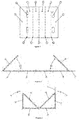
Figure 1 shows a layout of the sheet starting from which the tubular structural profile is created, indicating the fold lines (10, 11, 12, 13, 14) thereof and also the first external layers (1 and 2), second external layers (3 and 4), internal diagonal layers (5 and 6), at least one tongue (7) and in a corresponding manner at least one slot (8) thereof. -
Figure 2 shows a first step of folding the tubular structural profile, wherein the internal diagonal layers (5 and 6) are folded symmetrically at an angle greater than 90°. -
Figure 3 shows a second step of folding the tubular structural profile, wherein the second external layers (3 and 4) are folded symmetrically at a right angle. -
Figure 4 shows a third step of folding the tubular structural profile, wherein the first external layers (1 and 2) are folded on the first fold line and wherein at least one tongue (7) is folded and inserted inside of at least one slot (8), permitting the final closing of the profile. -
Figure 5 shows the tubular structural profile in a folded and closed state, indicating the position corresponding to the different elements thereof, such as the first external layers (1 and 2), the second external layers (3 and 4), the internal diagonal layers (5 and 6) located joining diagonally opposing fold lines in the profile, and the tongue (7) inserted inside the slot (8). -
Figure 6 shows a detail of the structural assembly of the tubular structural profile on an angle profile (9), for the solidarity of the structure formed starting from the profile, permitting a firm joining of profiles collinear with each other, wherein the internal diagonal layers (7 and 8) are shorter, in order to create the space required for the angle profile (9). -
Figure 7 shows a layout of the sheet starting from which the tubular structural profile is created, wherein the first fold line (10) thereof is formed by two parallel trajectories, separated from each other by a distance similar to twice the thickness of the material of the sheet. -
Figure 8 shows an example of a break (15) in the second external layers (3 and 4) and in the two internal diagonal layers (5 and 6), in a symmetrical manner, in order to create an engaging area (15) for transverse structural profiles which make up a set of elements of a composite structure and/or to permit a collinear assembly of the tubular structural profile with an angle profile which has transverse extensions. -
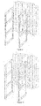
Figures 9, 10 ,11, 12 and13 show a sequence of execution of one of the manners of application of the composite structure using the tubular structural profile and the engaging thereof, corresponding to a piece of furniture, whereinFigure 9 shows two structural frames formed starting from folded sheets, which end on the sides thereof in angle profiles, both frames being parallel to each other, and wherein furthermore there is a first sheet with cuts and layouts of folds of the structural profile, with allowances for engaging transverse profiles, which are located behind the two frames.Figure 10 shows a first wedging between both frames, wherein one of the first external layers of each tubular structural profile is positioned wedged against one of the wings of the angle profile of one of the sides of each frame.Figure 11 shows a next step of execution, wherein a second sheet has been added with cuts and layouts of folds of the structural profile, with allowances for engaging transverse profiles, similar to the first one, both wedged with the two frames, wherein furthermore a first structural tray has also been installed in the area of the base of the composite structure, which in at least two of the opposing edges thereof contains folds which form tubular profiles, after which the lower portions of the sheets with cuts and layouts of folds of the structural profile have been folded and closed around the wings with the angle profile of the frames, creating a locking of the first tray and creating an engaging area in 4 corners for a second tray.Figure 12 shows the entry of the second structural tray to rest on the engaging of 4 corners, after which tubular structural profiles will be folded and closed around the wings with the angle profile of the frames on a second level.Figure 13 shows the final step of the execution, wherein the different levels of structural profiles have been folded and closed around the frames and the trays have been installed, remaining locked, culminating in the installation of one last tray on the upper portion.
Claims (7)
- A tubular structural profile, manufactured starting from the folding and cutting of a sheet of semi-rigid and foldable material, with high rigidity against bending, compression and torsion, the external contour of which comprises 4 substantially orthogonal layers joined at fold lines and an internal section, located diagonally joining two opposing fold lines, CHARACTERISED in that:a) the sheet of semi-rigid material has 6 rectangular, adjacent and parallel sections, separated from each other by fold lines, wherein the two central sections correspond to two first external layers (1 and 2), separated by a first fold line (10), followed towards the ends of two second external layers (3 and 4), separated from the first external layers by two second fold lines (11 and 12), and next, in a symmetrical manner two internal diagonal layers (5 and 6), separated from the second external layers by two third fold lines (13 and 14);b) each fold is performed in a single rotation direction, wherein the folding of the sheet on the third fold lines (13 and 14) is performed at a rotation angle greater than 90° in order to position the two diagonal layers, in order to then perform the folding of the sheet on the second fold lines (11 and 12) at a substantially right angle, followed by the folding on the first fold line (10) at a substantially right angle;c) on one of the third fold lines (13 and 14), cutting lines are positioned for at least one tongue (7), which coincides with at least one slot (8) located on the third opposing fold line, such that, during the folding, the tubular structural profile is closed by means of the coming together of both third fold lines (13 and 14) and both internal diagonal layers (5 and 6), and by means of the insertion of at least one tongue (7) in its corresponding slot (8), preventing the profile from opening during the structural performance thereof.
- The tubular structural profile of claim 1, CHARACTERISED in that the first fold line (10) is divided into two parallel rectilinear trajectories, separated from each other by a distance similar to twice the thickness of the material of the sheet, so that during the folding a surface comprised between both trajectories comes into contact in a more integral manner with the external borders of the two internal diagonal layers (5 and 6), such that it produces an increase in the strength and structural stability of the profile.
- A construction system, based on a tubular structural profile which is manufactured starting from the folding and cutting of a sheet of semi-rigid and foldable material, with high rigidity against bending, compression and torsion, the external contour of which comprises 4 substantially orthogonal layers joined at fold lines and an internal section, located diagonally joining two opposing fold lines, CHARACTERISED in that:a) the sheet of semi-rigid material has 6 rectangular, adjacent and parallel sections, separated from each other by fold lines, wherein the two central sections correspond to two first external layers (1 and 2), separated by a first fold line (10), followed towards the ends of two second external layers (3 and 4), separated from the first external layers by two second fold lines (11 and 12), and next, in a symmetrical manner two internal diagonal layers (5 and 6), separated from the second external layers by two third fold lines (13 and 14);b) each fold is performed in a single rotation direction, wherein the folding of the sheet on the third fold lines (13 and 14) is performed at a rotation angle greater than 90° in order to position the two diagonal layers, in order to then perform the folding of the sheet on the second fold lines (11 and 12) at a substantially right angle, followed by the folding on the first fold line (10) at a substantially right angle;c) on one of the third fold lines (13 and 14), cutting lines are positioned for at least one tongue (7), which coincides with at least one slot (8) located on the third opposing fold line, such that, during the folding, the tubular structural profile is closed by means of the coming together of both third fold lines (13 and 14) and both internal diagonal layers (5 and 6), and by means of the insertion of at least one tongue (7) in its corresponding slot (8), preventing the profile from opening during the structural performance thereof,d) the tubular structural profile has at least one break (15) in the second external layers (3 and 4) and in the two internal diagonal layers (5 and 6), in a symmetrical manner, which permits the creation of an engaging area for transverse structural profiles which make up a set of elements of a composite structure.
- The construction system of claim 3, CHARACTERISED in that the first fold line (10) is divided into two parallel rectilinear trajectories, separated from each other by a distance similar to twice the thickness of the material of the sheet, so that during the folding a surface comprised between both trajectories comes into contact in a more integral manner with the external borders of the two internal diagonal layers (5 and 6), such that it produces an increase in the strength and structural stability of the profile.
- The construction system of claims 3 to 4, CHARACTERISED in that the width of the two internal diagonal layers (5 and 6) of a tubular structural profile is less than the internal diagonal distance between two opposing fold lines, in order to create a fitted space for folding the profile around an angle profile (9), thus permitting the structural solidarity of structural profiles collinear with each other.
- The construction system of claim 5, CHARACTERISED in that the angle profile (17) contains extensions transverse to the longitudinal axis thereof, which join it to at least one other angle profile substantially parallel to the first one, and in that the breaks in the second external layers (3 and 4) and in the two internal diagonal layers (5 and 6) preferably coincide with these extensions.
- A transverse cross section of a tubular structural profile manufactured starting from the folding and cutting of a sheet of semi-rigid and foldable material, with high rigidity against bending, compression and torsion, the external contour of which is substantially rectangular and comprises 4 external rectilinear trajectories joined at creases with substantially right angles of deflection, and an internal section, located diagonally joining diagonally opposing creases, CHARACTERISED in that:a) the transverse cross section has a total of 6 rectilinear trajectories, wherein the last two rectilinear trajectories are located towards the ends of the 4 external rectilinear trajectories;b) the internal section is formed by a parallel, symmetrical and adjacent positioning of the last two rectilinear trajectories;c) each crease in the transverse cross section has a direction of rotation in the same orientation and direction;d) the creases corresponding to joints between each of the last rectilinear trajectories and the consequent external rectilinear trajectory thereof have an angle of deflection greater than 90° and less than 180°.
Applications Claiming Priority (1)
| Application Number | Priority Date | Filing Date | Title |
|---|---|---|---|
| PCT/CL2018/050118 WO2020107132A1 (en) | 2018-11-29 | 2018-11-29 | Tubular structural profile and construction system, produced by cutting and folding a semi-rigid and foldable sheet, with 4 substantially orthoginal layers joined at fold lines and internal diagonal layers joining two opposing fold lines, and at least one tongue which coincides with at least one slot |
Publications (3)
| Publication Number | Publication Date |
|---|---|
| EP3889058A1 true EP3889058A1 (en) | 2021-10-06 |
| EP3889058A4 EP3889058A4 (en) | 2022-06-01 |
| EP3889058B1 EP3889058B1 (en) | 2025-01-22 |
Family
ID=70853640
Family Applications (1)
| Application Number | Title | Priority Date | Filing Date |
|---|---|---|---|
| EP18941711.6A Active EP3889058B1 (en) | 2018-11-29 | 2018-11-29 | Tubular structural profile and construction system |
Country Status (8)
| Country | Link |
|---|---|
| US (1) | US11490746B2 (en) |
| EP (1) | EP3889058B1 (en) |
| CA (1) | CA3121016A1 (en) |
| CO (1) | CO2021006508A2 (en) |
| ES (1) | ES3022915T3 (en) |
| MX (1) | MX2021006109A (en) |
| PL (1) | PL3889058T3 (en) |
| WO (1) | WO2020107132A1 (en) |
Families Citing this family (4)
| Publication number | Priority date | Publication date | Assignee | Title |
|---|---|---|---|---|
| PL3889058T3 (en) * | 2018-11-29 | 2025-08-11 | Carlos Tomas Veraza Osorio Publicidad Spa | Tubular structural profile and construction system |
| US11713160B1 (en) | 2022-07-15 | 2023-08-01 | Multi Packaging Solutions, Inc. | Sustainable rack and display system |
| US20240246721A1 (en) * | 2023-01-20 | 2024-07-25 | Afa Systems Ltd. | Pallet and pallet forming system and method |
| JP2025108018A (en) * | 2024-01-10 | 2025-07-23 | 京セラドキュメントソリューションズ株式会社 | Packaging materials |
Family Cites Families (50)
| Publication number | Priority date | Publication date | Assignee | Title |
|---|---|---|---|---|
| US2444183A (en) * | 1945-07-14 | 1948-06-29 | Norman L Cahners | Fiberboard portable platform |
| US2609136A (en) * | 1947-09-19 | 1952-09-02 | Container Corp | Packing element |
| GB928141A (en) | 1961-02-13 | 1963-06-06 | Albert E Reed & Company Ltd | Improvements in or relating to load carrying pallets |
| US3115105A (en) * | 1962-01-02 | 1963-12-24 | Bird & Son | Pallet and support station useful in pallets and the like |
| GB957762A (en) * | 1962-03-12 | 1964-05-13 | Alpha Containers Ltd | Improvements in the construction of stillage or platform elements |
| US3292796A (en) * | 1965-02-11 | 1966-12-20 | Paper Products Dev Corp | Floor stand of knockdown character |
| CH498605A (en) * | 1968-11-04 | 1970-11-15 | Ed Mueller Hermann | Support column |
| US3606230A (en) * | 1969-06-13 | 1971-09-20 | George M Hargreaves | Cartop load supporting device |
| US3877396A (en) * | 1973-07-30 | 1975-04-15 | Coca Cola Co | Knockdown display rack |
| CA1062664A (en) * | 1974-06-18 | 1979-09-18 | Bruno Roveroni | Decorating or shelf system |
| US4102525A (en) * | 1977-02-14 | 1978-07-25 | Robert Norman Albano | Knockdown support and spacer for bookshelves |
| US4231299A (en) * | 1979-06-15 | 1980-11-04 | The Mead Corporation | Merchandising display |
| US4248350A (en) * | 1979-10-22 | 1981-02-03 | Westvaco Corporation | Corner post with integral lock |
| US4333622A (en) | 1980-04-30 | 1982-06-08 | Albano Robert N | Knockdown spacer for bookshelves and the like |
| US4563377A (en) | 1983-02-14 | 1986-01-07 | Finsen S.P.A. | High-strength tubular beam of folded corrugated cardboard |
| US4595137A (en) * | 1985-06-17 | 1986-06-17 | Kupersmit Julius B | Reinforcing element for collapsible container |
| US4864940A (en) * | 1988-06-08 | 1989-09-12 | Tate Containers, Inc. | Collapsible pallet |
| US5222444A (en) * | 1992-01-29 | 1993-06-29 | American Corrugated Products, Inc. | Paperboard runners and paperboard pallets constructed therewith |
| US5339746A (en) * | 1992-06-02 | 1994-08-23 | Rock-Tenn Company | Pallet leg assembly |
| US5394810A (en) * | 1993-03-18 | 1995-03-07 | Hmv Enterprises, Inc. | Foldable furniture |
| US5423270A (en) * | 1993-03-29 | 1995-06-13 | Gate Pallet Systems, Inc. | Pallet stringer |
| US5660119A (en) * | 1996-06-28 | 1997-08-26 | Plastic Systems, Inc. | Lightweight structural beam |
| ES2134154B1 (en) * | 1997-10-07 | 2000-04-16 | Videcart Sa | TRAY FOR THE TRANSPORT OF PRODUCTS. |
| FR2769812B3 (en) | 1997-10-21 | 1999-12-03 | Marin S Communication | FOLDING SEAT ELEMENT |
| US6539880B2 (en) * | 2001-01-08 | 2003-04-01 | Walter Brian Simms | Corrugated paperboard pallet rail |
| US7111735B2 (en) * | 2004-10-01 | 2006-09-26 | Sonoco Development, Inc. | Base for post in post product packaging and display system |
| US7281648B2 (en) * | 2004-11-19 | 2007-10-16 | Sonoco Development, Inc. | Tray with means for holding a vertical post |
| US7546927B2 (en) * | 2005-01-13 | 2009-06-16 | Lowry James W | Product tray insert |
| ES2281244B1 (en) * | 2005-06-01 | 2008-09-16 | Miralles Cartonajes, S.A. | "MODULAR SHELVING". |
| US7909168B2 (en) | 2006-12-16 | 2011-03-22 | Alexander Virvo | Slide and lock display system |
| US20090032432A1 (en) * | 2007-07-02 | 2009-02-05 | Great Northern Corporation | Stackable pallet system including v-shaped corner supports |
| US7905183B2 (en) * | 2008-01-29 | 2011-03-15 | Gibson Daniel J | Structural cardboard runner, pallet, shipping article |
| US20090223421A1 (en) * | 2008-03-05 | 2009-09-10 | James A. Donovan | Shipping pallet |
| DE202008011113U1 (en) * | 2008-08-21 | 2010-01-07 | Wellcarton Verpackungen Und Displays Gmbh & Co. | Shelf with cardboard folding elements |
| WO2010057522A1 (en) | 2008-11-18 | 2010-05-27 | Swissfiber Ag | Construction elements for buildings |
| FR2951705B1 (en) | 2009-10-22 | 2011-11-04 | Cartonnages Ramade | SHEET FOLDING FORMING PALLET LONGERON |
| DE112010004678B4 (en) * | 2009-12-03 | 2015-04-16 | Jason S. Erdie | Triangular transport container with polygonal inner support |
| US9185984B2 (en) * | 2010-09-14 | 2015-11-17 | North Carolina Agricultural And Technical State University | Folded sheets of material for use as a structural member and assembly thereof |
| US8833573B2 (en) * | 2012-01-16 | 2014-09-16 | Sonoco Development, Inc | Dividerless packaging system for shipping and displaying palletized products |
| US8783547B2 (en) * | 2012-02-09 | 2014-07-22 | Southern Missouri Containers, Inc. | Corrugated paper structure |
| US9743782B1 (en) * | 2014-01-13 | 2017-08-29 | Vanguard Packaging, Inc. | Retail upright shelf extender |
| US9655446B2 (en) * | 2013-09-19 | 2017-05-23 | Innovative Packaging Designs L.P. | Display tray |
| US9428298B2 (en) * | 2013-11-05 | 2016-08-30 | Sonoco Development, Inc. | Dividerless palletized packaging system with interlocking tray and corner posts |
| CA2946671C (en) * | 2014-04-29 | 2022-09-13 | Julio MIARNAU FERNANDEZ | Modular structure for cardboard tower-like displays |
| US9783333B1 (en) * | 2015-01-27 | 2017-10-10 | Packaging Corporation Of America | Post construction and tiered palletizable container comprising such posts |
| US10315798B2 (en) * | 2015-06-22 | 2019-06-11 | Menasha Corporation | Stackable pallet display |
| US10568422B2 (en) * | 2016-04-15 | 2020-02-25 | Menasha Corporation | Corrugated hutch |
| US9826843B1 (en) * | 2016-11-11 | 2017-11-28 | Sonoco Development, Inc. | Stackable shelf tray for a retail display |
| US10351297B2 (en) * | 2017-03-21 | 2019-07-16 | Preferred Packaging Solutions, Inc. | Light weight folded corrugated pallet |
| PL3889058T3 (en) * | 2018-11-29 | 2025-08-11 | Carlos Tomas Veraza Osorio Publicidad Spa | Tubular structural profile and construction system |
-
2018
- 2018-11-29 PL PL18941711.6T patent/PL3889058T3/en unknown
- 2018-11-29 US US17/296,315 patent/US11490746B2/en active Active
- 2018-11-29 MX MX2021006109A patent/MX2021006109A/en unknown
- 2018-11-29 CA CA3121016A patent/CA3121016A1/en active Pending
- 2018-11-29 WO PCT/CL2018/050118 patent/WO2020107132A1/en not_active Ceased
- 2018-11-29 ES ES18941711T patent/ES3022915T3/en active Active
- 2018-11-29 EP EP18941711.6A patent/EP3889058B1/en active Active
-
2021
- 2021-05-20 CO CONC2021/0006508A patent/CO2021006508A2/en unknown
Also Published As
| Publication number | Publication date |
|---|---|
| WO2020107132A1 (en) | 2020-06-04 |
| BR112021009875A2 (en) | 2022-02-01 |
| US11490746B2 (en) | 2022-11-08 |
| CA3121016A1 (en) | 2020-06-04 |
| PL3889058T3 (en) | 2025-08-11 |
| CO2021006508A2 (en) | 2021-05-31 |
| EP3889058A4 (en) | 2022-06-01 |
| ES3022915T3 (en) | 2025-05-29 |
| US20210393053A1 (en) | 2021-12-23 |
| EP3889058B1 (en) | 2025-01-22 |
| MX2021006109A (en) | 2021-09-23 |
Similar Documents
| Publication | Publication Date | Title |
|---|---|---|
| EP3889058A1 (en) | Tubular structural profile and construction system, produced by cutting and folding a semi-rigid and foldable sheet, with 4 substantially orthoginal layers joined at fold lines and internal diagonal layers joining two opposing fold lines, and at least one tongue which coincides with at least one slot | |
| US8479666B2 (en) | Interlock for nested top and bottom panels of foldably constructed force-resisting structures | |
| US5377857A (en) | Stackable bin with collapsible corner construction | |
| JP6605045B2 (en) | Foldable assembly type pallet and bottom plate blank used therefor | |
| US3952672A (en) | Corrugated disposable pallet | |
| US5660119A (en) | Lightweight structural beam | |
| US20110245059A1 (en) | Foldably constructed force-resisting structures having interior vertical support ribs | |
| AU2005254543B2 (en) | Paperboard container with bottom support | |
| US5337680A (en) | Fiberboard pallet | |
| US3006590A (en) | Corrugated pallet | |
| US6669082B1 (en) | Compression supporting package divider set | |
| EP3063074B1 (en) | Preassembled display with automatic stackable supports | |
| WO2006011093A1 (en) | Container | |
| US20200047942A1 (en) | Container with multipiece body | |
| EP3604150A1 (en) | Octagonal box having an automatic base | |
| CA2884508A1 (en) | Product container and reinforcement for a product container | |
| RU117137U1 (en) | TRANSPORT GOVERNING CONTAINER (OPTIONS) | |
| RU117896U1 (en) | TRANSPORT GOVERNING CONTAINER (OPTIONS) | |
| JP7020142B2 (en) | Packaging container | |
| JP6800674B2 (en) | How to make a container | |
| GB2361225A (en) | Collapsible pallet carton | |
| JP5528033B2 (en) | Pallet integrated container | |
| BR112021009875B1 (en) | TUBULAR STRUCTURAL PROFILE AND CONSTRUCTION SYSTEM, MANUFACTURED BY CUTTING AND BENDING A SEMIRIGID AND FOLDABLE SHEET, WITH FOUR ORTHOGONAL SHEETS UNITED IN AN INTERNAL FOLD AND DIAGONAL LINES, WHICH JOIN TWO OPPOSING BEND LINES AND AT LEAST ONE FLAP THAT COINCIDES WITH AT LEAST ONE SLOT | |
| GB1597844A (en) | Fibreboard panel constructions | |
| JP2006143244A (en) | Corrugated fiberboard-made girder |
Legal Events
| Date | Code | Title | Description |
|---|---|---|---|
| STAA | Information on the status of an ep patent application or granted ep patent |
Free format text: STATUS: THE INTERNATIONAL PUBLICATION HAS BEEN MADE |
|
| PUAI | Public reference made under article 153(3) epc to a published international application that has entered the european phase |
Free format text: ORIGINAL CODE: 0009012 |
|
| STAA | Information on the status of an ep patent application or granted ep patent |
Free format text: STATUS: REQUEST FOR EXAMINATION WAS MADE |
|
| 17P | Request for examination filed |
Effective date: 20210624 |
|
| AK | Designated contracting states |
Kind code of ref document: A1 Designated state(s): AL AT BE BG CH CY CZ DE DK EE ES FI FR GB GR HR HU IE IS IT LI LT LU LV MC MK MT NL NO PL PT RO RS SE SI SK SM TR |
|
| DAX | Request for extension of the european patent (deleted) | ||
| RAV | Requested validation state of the european patent: fee paid |
Extension state: MA Effective date: 20210624 |
|
| REG | Reference to a national code |
Ref country code: DE Ref legal event code: R079 Free format text: PREVIOUS MAIN CLASS: B65D0019000000 Ipc: A47B0096140000 Ref document number: 602018078788 Country of ref document: DE |
|
| A4 | Supplementary search report drawn up and despatched |
Effective date: 20220503 |
|
| RIC1 | Information provided on ipc code assigned before grant |
Ipc: B65D 19/38 20060101ALI20220426BHEP Ipc: A47F 5/11 20060101ALI20220426BHEP Ipc: A47B 96/14 20060101AFI20220426BHEP |
|
| P01 | Opt-out of the competence of the unified patent court (upc) registered |
Effective date: 20230517 |
|
| GRAP | Despatch of communication of intention to grant a patent |
Free format text: ORIGINAL CODE: EPIDOSNIGR1 |
|
| STAA | Information on the status of an ep patent application or granted ep patent |
Free format text: STATUS: GRANT OF PATENT IS INTENDED |
|
| RIC1 | Information provided on ipc code assigned before grant |
Ipc: E04C 3/07 20060101ALI20240807BHEP Ipc: B65D 19/38 20060101ALI20240807BHEP Ipc: B65D 5/44 20060101ALI20240807BHEP Ipc: A47F 5/11 20060101ALI20240807BHEP Ipc: A47B 96/14 20060101AFI20240807BHEP |
|
| INTG | Intention to grant announced |
Effective date: 20240823 |
|
| GRAS | Grant fee paid |
Free format text: ORIGINAL CODE: EPIDOSNIGR3 |
|
| GRAA | (expected) grant |
Free format text: ORIGINAL CODE: 0009210 |
|
| STAA | Information on the status of an ep patent application or granted ep patent |
Free format text: STATUS: THE PATENT HAS BEEN GRANTED |
|
| AK | Designated contracting states |
Kind code of ref document: B1 Designated state(s): AL AT BE BG CH CY CZ DE DK EE ES FI FR GB GR HR HU IE IS IT LI LT LU LV MC MK MT NL NO PL PT RO RS SE SI SK SM TR |
|
| REG | Reference to a national code |
Ref country code: GB Ref legal event code: FG4D |
|
| REG | Reference to a national code |
Ref country code: CH Ref legal event code: EP |
|
| REG | Reference to a national code |
Ref country code: IE Ref legal event code: FG4D |
|
| REG | Reference to a national code |
Ref country code: DE Ref legal event code: R096 Ref document number: 602018078788 Country of ref document: DE |
|
| REG | Reference to a national code |
Ref country code: NL Ref legal event code: FP |
|
| REG | Reference to a national code |
Ref country code: ES Ref legal event code: FG2A Ref document number: 3022915 Country of ref document: ES Kind code of ref document: T3 Effective date: 20250529 |
|
| PG25 | Lapsed in a contracting state [announced via postgrant information from national office to epo] |
Ref country code: RS Free format text: LAPSE BECAUSE OF FAILURE TO SUBMIT A TRANSLATION OF THE DESCRIPTION OR TO PAY THE FEE WITHIN THE PRESCRIBED TIME-LIMIT Effective date: 20250422 |
|
| PG25 | Lapsed in a contracting state [announced via postgrant information from national office to epo] |
Ref country code: FI Free format text: LAPSE BECAUSE OF FAILURE TO SUBMIT A TRANSLATION OF THE DESCRIPTION OR TO PAY THE FEE WITHIN THE PRESCRIBED TIME-LIMIT Effective date: 20250122 |
|
| REG | Reference to a national code |
Ref country code: LT Ref legal event code: MG9D |
|
| PG25 | Lapsed in a contracting state [announced via postgrant information from national office to epo] |
Ref country code: IS Free format text: LAPSE BECAUSE OF FAILURE TO SUBMIT A TRANSLATION OF THE DESCRIPTION OR TO PAY THE FEE WITHIN THE PRESCRIBED TIME-LIMIT Effective date: 20250522 Ref country code: NO Free format text: LAPSE BECAUSE OF FAILURE TO SUBMIT A TRANSLATION OF THE DESCRIPTION OR TO PAY THE FEE WITHIN THE PRESCRIBED TIME-LIMIT Effective date: 20250422 |
|
| REG | Reference to a national code |
Ref country code: AT Ref legal event code: MK05 Ref document number: 1760759 Country of ref document: AT Kind code of ref document: T Effective date: 20250122 |
|
| PG25 | Lapsed in a contracting state [announced via postgrant information from national office to epo] |
Ref country code: HR Free format text: LAPSE BECAUSE OF FAILURE TO SUBMIT A TRANSLATION OF THE DESCRIPTION OR TO PAY THE FEE WITHIN THE PRESCRIBED TIME-LIMIT Effective date: 20250122 |
|
| PG25 | Lapsed in a contracting state [announced via postgrant information from national office to epo] |
Ref country code: LV Free format text: LAPSE BECAUSE OF FAILURE TO SUBMIT A TRANSLATION OF THE DESCRIPTION OR TO PAY THE FEE WITHIN THE PRESCRIBED TIME-LIMIT Effective date: 20250122 Ref country code: PT Free format text: LAPSE BECAUSE OF FAILURE TO SUBMIT A TRANSLATION OF THE DESCRIPTION OR TO PAY THE FEE WITHIN THE PRESCRIBED TIME-LIMIT Effective date: 20250522 |
|
| PG25 | Lapsed in a contracting state [announced via postgrant information from national office to epo] |
Ref country code: BG Free format text: LAPSE BECAUSE OF FAILURE TO SUBMIT A TRANSLATION OF THE DESCRIPTION OR TO PAY THE FEE WITHIN THE PRESCRIBED TIME-LIMIT Effective date: 20250122 Ref country code: GR Free format text: LAPSE BECAUSE OF FAILURE TO SUBMIT A TRANSLATION OF THE DESCRIPTION OR TO PAY THE FEE WITHIN THE PRESCRIBED TIME-LIMIT Effective date: 20250423 |
|
| PG25 | Lapsed in a contracting state [announced via postgrant information from national office to epo] |
Ref country code: AT Free format text: LAPSE BECAUSE OF FAILURE TO SUBMIT A TRANSLATION OF THE DESCRIPTION OR TO PAY THE FEE WITHIN THE PRESCRIBED TIME-LIMIT Effective date: 20250122 |
|
| PG25 | Lapsed in a contracting state [announced via postgrant information from national office to epo] |
Ref country code: SE Free format text: LAPSE BECAUSE OF FAILURE TO SUBMIT A TRANSLATION OF THE DESCRIPTION OR TO PAY THE FEE WITHIN THE PRESCRIBED TIME-LIMIT Effective date: 20250122 |
|
| PG25 | Lapsed in a contracting state [announced via postgrant information from national office to epo] |
Ref country code: SM Free format text: LAPSE BECAUSE OF FAILURE TO SUBMIT A TRANSLATION OF THE DESCRIPTION OR TO PAY THE FEE WITHIN THE PRESCRIBED TIME-LIMIT Effective date: 20250122 |
|
| PG25 | Lapsed in a contracting state [announced via postgrant information from national office to epo] |
Ref country code: DK Free format text: LAPSE BECAUSE OF FAILURE TO SUBMIT A TRANSLATION OF THE DESCRIPTION OR TO PAY THE FEE WITHIN THE PRESCRIBED TIME-LIMIT Effective date: 20250122 |
|
| PG25 | Lapsed in a contracting state [announced via postgrant information from national office to epo] |
Ref country code: EE Free format text: LAPSE BECAUSE OF FAILURE TO SUBMIT A TRANSLATION OF THE DESCRIPTION OR TO PAY THE FEE WITHIN THE PRESCRIBED TIME-LIMIT Effective date: 20250122 |
|
| REG | Reference to a national code |
Ref country code: DE Ref legal event code: R097 Ref document number: 602018078788 Country of ref document: DE |
|
| PG25 | Lapsed in a contracting state [announced via postgrant information from national office to epo] |
Ref country code: RO Free format text: LAPSE BECAUSE OF FAILURE TO SUBMIT A TRANSLATION OF THE DESCRIPTION OR TO PAY THE FEE WITHIN THE PRESCRIBED TIME-LIMIT Effective date: 20250122 |
|
| PG25 | Lapsed in a contracting state [announced via postgrant information from national office to epo] |
Ref country code: SK Free format text: LAPSE BECAUSE OF FAILURE TO SUBMIT A TRANSLATION OF THE DESCRIPTION OR TO PAY THE FEE WITHIN THE PRESCRIBED TIME-LIMIT Effective date: 20250122 |
|
| PLBE | No opposition filed within time limit |
Free format text: ORIGINAL CODE: 0009261 |
|
| STAA | Information on the status of an ep patent application or granted ep patent |
Free format text: STATUS: NO OPPOSITION FILED WITHIN TIME LIMIT |
|
| PGFP | Annual fee paid to national office [announced via postgrant information from national office to epo] |
Ref country code: NL Payment date: 20251126 Year of fee payment: 8 |
|
| 26N | No opposition filed |
Effective date: 20251023 |
|
| PGFP | Annual fee paid to national office [announced via postgrant information from national office to epo] |
Ref country code: DE Payment date: 20251128 Year of fee payment: 8 |
|
| PGFP | Annual fee paid to national office [announced via postgrant information from national office to epo] |
Ref country code: GB Payment date: 20251127 Year of fee payment: 8 |
|
| PGFP | Annual fee paid to national office [announced via postgrant information from national office to epo] |
Ref country code: IT Payment date: 20251119 Year of fee payment: 8 |
|
| PGFP | Annual fee paid to national office [announced via postgrant information from national office to epo] |
Ref country code: FR Payment date: 20251125 Year of fee payment: 8 |
|
| PGFP | Annual fee paid to national office [announced via postgrant information from national office to epo] |
Ref country code: CZ Payment date: 20251105 Year of fee payment: 8 |
|
| PGFP | Annual fee paid to national office [announced via postgrant information from national office to epo] |
Ref country code: PL Payment date: 20251112 Year of fee payment: 8 |
|
| PGFP | Annual fee paid to national office [announced via postgrant information from national office to epo] |
Ref country code: ES Payment date: 20251201 Year of fee payment: 8 |
|
| VS25 | Lapsed in a validation state [announced via postgrant information from nat. office to epo] |
Ref country code: MA Free format text: LAPSE BECAUSE OF FAILURE TO SUBMIT A TRANSLATION OF THE DESCRIPTION OR TO PAY THE FEE WITHIN THE PRESCRIBED TIME-LIMIT; INVALID AB INITIO Effective date: 20181129 |