EP3888239B1 - Triboelektrischer generator - Google Patents
Triboelektrischer generator Download PDFInfo
- Publication number
- EP3888239B1 EP3888239B1 EP19816849.4A EP19816849A EP3888239B1 EP 3888239 B1 EP3888239 B1 EP 3888239B1 EP 19816849 A EP19816849 A EP 19816849A EP 3888239 B1 EP3888239 B1 EP 3888239B1
- Authority
- EP
- European Patent Office
- Prior art keywords
- power generation
- triboelectric
- generation modules
- contact
- actuating elements
- Prior art date
- Legal status (The legal status is an assumption and is not a legal conclusion. Google has not performed a legal analysis and makes no representation as to the accuracy of the status listed.)
- Active
Links
Images


Classifications
-
- H—ELECTRICITY
- H02—GENERATION; CONVERSION OR DISTRIBUTION OF ELECTRIC POWER
- H02N—ELECTRIC MACHINES NOT OTHERWISE PROVIDED FOR
- H02N1/00—Electrostatic generators or motors using a solid moving electrostatic charge carrier
- H02N1/04—Friction generators
Definitions
- the present invention relates to a triboelectric generator for generating electrical power using the triboelectric effect.
- Triboelectric generators have been developed which use contact-separation movement to generate electrical power through the triboelectric effect.
- the contact-separation movement only induces intermittent current as two surfaces come into contact, with the polarity of the current then reversing when the surfaces are separated.
- the output current produced by such contact-separation triboelectric generators is therefore alternating and intermittent, limiting the usefulness of such devices.
- KR 2017 0002363 A discloses a triboelectric generator which comprises a rotating electrode, a frictional electrode periodically formed at regular intervals inside a frictional electrode fixing plate formed on an outer part of the rotating electrode, and having a plurality of fine protrusion structures formed on the surface, and a triboelectric generating layer on the surface of an end of the rotating electrode.
- CN 105 897 036 A discloses a friction electrostatic generator employing wind energy as power.
- a triboelectric generator according to claim 1.
- the one or more actuating elements are arranged so as to come into contact with the power generation modules at different times during the relative movement of the first and second bodies.
- the relative movement comprises relative linear movement of the first and second bodies.
- the one or more actuating elements comprises a plurality of actuating elements, and a distance between adjacent ones of the power generation modules is different to a distance between adjacent ones of the plurality of actuating elements, such that said adjacent actuating elements contact said adjacent power generation modules at different times during the relative linear movement.
- the relative movement comprises rotation of the first body relative to the second body.
- the one or more actuating elements comprises a plurality of actuating elements, and an angular spacing between adjacent ones of the power generation modules is different to an angular spacing between adjacent ones of the plurality of actuating elements, such that said adjacent actuating elements contact said adjacent power generation modules at different times during the relative rotation of the first and second bodies.
- the first body at least partially surrounds the second body such that the second body rotates within the first body, and each one of the plurality of power generation modules is disposed on the first body and extends inwardly towards the second body from the first body.
- the second body at least partially surrounds the first body such that the first body rotates within the second body, and each one of the plurality of power generation modules extends outwardly from the first body towards the second body.
- the plurality of power generation modules comprise a plurality of first power generation modules and one or more of the plurality of actuating elements comprise a second power generation module, such that when one of the first power generation modules is actuated by the second power generation module to produce electrical power, the second power generation module is simultaneously actuated by said one of the first power generation modules to produce additional electrical power.
- the power generation modules are arranged to come into contact with said other surface at substantially the same time, the triboelectric generator further comprising means for delaying the power output of one power generation module relative to other ones of the power generation modules, such that the electrical power generated by said one power generation module is supplied to the common output at a different time to the electrical power generated by said other ones of the power generation modules.
- the means for delaying the power output comprises a delay circuit.
- the delay circuit comprises one or more active electrical components arranged to be powered from the common output.
- the triboelectric generator further comprises one or more rectifiers configured to rectify an electric current generated by each of the plurality of power generation modules and supply rectified electric current to the common output.
- each power generation module comprises first and second electrodes, wherein the power generation component and the first contact surface are disposed between the first and second electrodes such that the oscillation of the power generation component induces a potential difference between the first and second electrodes, and wherein the first and second electrodes are connected to the common output.
- the triboelectric generator further comprises a plurality of rectifiers each connected to a respective one of the plurality of power generation modules, each rectifier comprising a first input, a second input, a positive output and a negative output, wherein the common output comprises a positive terminal and a negative terminal, and wherein the first electrode of one of the power generation modules is electrically connected to the first input of a respective one of the plurality of rectifiers, the second electrode of said one of the power generation modules is electrically connected to the second input of said one of the plurality of rectifiers, the positive output of said one of the plurality of rectifiers is connected to the positive terminal, and the negative output of said one of the plurality of rectifiers is connected to the negative terminal.
- the first contact surface consists of the first electrode.
- the first contact surface comprises a triboelectric layer disposed on the first electrode, such that the power generation component repeatedly makes contact with the triboelectric layer during the oscillation of the power generation component.
- the triboelectric material is formed as a sheet, and the first and second electrodes can be arranged to overlap at least part of the sheet of triboelectric material.
- the first contact surface comprises a different material to the power generation component.
- each power generation module further comprises a second contact surface disposed on an opposite side of the power generation component to the first contact surface, such that the power generation component alternately contacts the first and second contact surfaces during the oscillation of the power generation component.
- the power generation component and the first contact surface extend away from a surface of the first body towards the one or more actuating elements, the power generation component extending further away from the first body than the first contact surface, and a separation distance between the first and second bodies is set such that during the relative movement of the first and second bodies, the one or more actuating elements contact the power generation component but not the first contact surface.
- the first contact surface has a higher stiffness than the power generation component.
- apparatus comprising first and second parts arranged to move relative to one another during normal operation of the apparatus, and a triboelectric generator according to the first aspect for harvesting electrical power from the relative movement of the first and second parts of the apparatus, wherein the first body of the triboelectric generator comprises or is physically connected to the first part of the apparatus, and the second body of the triboelectric generator comprises or is physically connected to the second part of the apparatus.
- the apparatus is configured to be worn on a human or animal body, such that movement of said human or animal body causes the first and second parts to move relative to one another.
- the apparatus comprises an item of clothing.
- the first and second parts comprise layers of material arranged to slide over one another.
- the apparatus comprises machinery configured to produce linear and/or rotational motion.
- the triboelectric generator 100 of the present embodiment comprises a first body 110 and a second body 120.
- the first body 110 and the second body 120 are configured to be moveable relative to each other.
- the first body 110 is pivotably connected to the second body 120, such that the second body 120 is free to rotate independently of the first body 110.
- the first and second bodies may be configured so as to permit different types of relative movement, such as linear and/or reciprocal movement.
- the triboelectric generator 100 further comprises a plurality of power generation modules 111 disposed on the first body 110, and one or more actuating elements 121 disposed on the second body 120.
- the actuating elements 121 may, for example, comprise protrusions integrally formed with the second body 120.
- the plurality of power generation modules 111 and the one or more actuating elements 121 are arranged on the first and second bodies 110, 120 such that relative movement of the first and second bodies 110, 120 can cause the one or more actuating elements 121 to come into contact with the plurality of power generation modules 111.
- Each power generation module 111 comprises triboelectric materials that can generate electrical power through the triboelectric effect when brought into contact with each other, and the plurality of power generation modules 111 are electrically connected to a common output 140, which comprises positive and negative terminals.
- each actuating element 121 disposed on the second body 120 may comprise a power generation module similar to the power generation modules 111 disposed on the first body. That is, the plurality of power generation modules may comprise a plurality of first power generation modules and one or more of the plurality of actuating elements may comprise a second power generation module, such that when one of the first power generation modules is actuated by the second power generation module to produce electrical power, the second power generation module is simultaneously actuated by said one of the first power generation modules to produce additional electrical power.
- the power generation modules 111, 121 on the first and second bodies 110, 120 can each act as actuating elements for one of the power generation modules 111, 121 on the other one of the first and second bodies 110, 120.
- the total power output of the triboelectric generator 100 can be increased, since electrical power is generated both by the power generation modules 111 on the first body 110 and by the power generation modules 121 on the second body 120.
- the triboelectric generator 100 comprises six power generation modules 111 and six actuating elements 121.
- the triboelectric generator may comprise a different number of power generation modules 111 and/or actuating elements 121.
- the six actuating elements 121 are distributed symmetrically around the second body 120 at regular angular intervals of 60°. It will be appreciated that different positions and angular spacing of the actuating elements 121 may be used in other embodiments, depending on the total number of actuating elements 121 included in the generator 100.
- an electric current is induced in the power generation module 111.
- Power can therefore be generated through a combination of the triboelectric effect and electrostatic induction, since the triboelectric effect results in charge separation when the two surfaces are brought into contact, and then an electric current is induced as the charged surfaces are subsequently separated and contacted.
- an output phase shift of 60° is obtained between adjacent power generation modules 111 by providing a different angular spacing between adjacent ones of the power generation modules 111 to the angular spacing between adjacent ones of the plurality of actuating elements 121.
- the actuating elements 121 make contact with the power generation modules 111 at different times during the relative rotation of the first and second bodies 110, 120, resulting in a corresponding phase shift between the electrical outputs of the power generation modules 111.
- the triboelectric generator 100 is configured such that the plurality of power generation modules 111 supply electrical power to the common output 140 at different times during the relative movement of the first and second bodies 110, 120, thereby to provide a more continuous supply of electrical power from the common output 140 in comparison to prior art devices which only produce a discontinuous sporadic output pulse.
- the electrical outputs of the plurality of power generation modules 111 can be rectified to provide a more direct current (DC)-like output.
- DC direct current
- Embodiments of the present invention can therefore be used to generate electric power through the triboelectric effect and supply power to DC components.
- conventional triboelectric generators only provide a momentary pulse of electrical power and so are not suitable for powering DC components.
- the triboelectric generator further comprises a plurality of rectifiers 130, each of which is connected to a respective one of the plurality of power generation modules 111.
- the plurality of rectifiers 130 are full bridge rectifiers, but in other embodiments different types of rectifier may be used.
- the outputs of the plurality of rectifiers 130 are connected to the common output 140.
- the outputs of the plurality of power generation modules 111 may be combined before rectification. However, under some circumstances, depending on the speed of the relative movement between the first and second bodies 110, 120, the phase shift between the plurality of power generation modules 111 may cause the outputs of two or more of the power generation modules 111 to cancel each other, reducing the total power output.
- the output of each power generation module 111 is rectified before combining the rectified outputs of the plurality of power generation modules 111.
- the first body 110 at least partially surrounds the second body 120 such that the second body 120 rotates within the first body 110.
- the plurality of power generation modules 111 are arranged around the first body 120 and extend inwardly towards the second body 120.
- the one or more actuating elements 121 extend outwardly from the second body 120 towards one or more of the power generation modules 111, so that the actuating elements 121 make contact with the power generation modules 111 as the first and second bodies 110, 120 rotate with respect to one another. This provides a compact arrangement which allows the overall volume of the triboelectric generator 100 to be reduced.
- the first and second bodies may be similar in size, and may be disposed along a common axis of rotation.
- the plurality of power generation modules may be disposed on a surface of the first body that faces the second body, and the one or more actuating elements (which may themselves be power generation modules, as described above) may be disposed on a surface of the second body that faces the first body, with the power generation modules and actuating elements being disposed at similar distances from the common axis.
- the surface of the first body can be considered as rotating against the surface of the second body, although it will be appreciated that the first and second bodies may not physically contact one another due to the presence of the power generation modules and actuating elements between the first and second bodies. This arrangement can allow the overall diameter of the triboelectric generator 100 to be reduced.
- the second body may at least partially surround the first body such that the first body rotates within the second body.
- the plurality of power generation modules can be arranged around the first body and can extend outwardly towards the second body, and the one or more actuating elements can extend inwardly from the second body towards one or more of the power generation modules. In this way, the positioning of the power generation modules and the actuating elements is inverted in comparison to the arrangement illustrated in Fig. 1 .
- This arrangement may be advantageous in applications where the first body will remain fixed relative to another apparatus that is connected to the common output to be powered by the generation, by allowing fixed electrical connections to be used between the power generation modules, the common output, and the apparatus.
- the power generation module 111 comprises a power generation component 203 comprising material that is capable of generating electrical power through the triboelectric effect when brought into contact with another surface.
- the power generation component 203 comprises a sheet of material.
- triboelectric material the material within the power generation component 203 that generates power through the triboelectric effect.
- the power generation component 203 and the other surface that is brought into contact with the power generation component 203 can be formed from any suitable combination of materials.
- the power generation component 203 and the other surface may comprise the same material. However, a higher power output may be achieved when different materials are used for the power generation component 203 and the other surface.
- the power generation component 203 is clamped at one end, and has a free (i.e. unsupported) end that is disposed to come into contact with the one or more actuating elements 121 during relative rotation of the first and second bodies 110, 120.
- the sheet of triboelectric material is elastically deflected.
- the power generation component 203 is released and springs back in the opposite direction to the direction in which the power generation component 203 was deflected by the actuating element 121.
- the power generation module 111 further comprises a first contact surface 201 and a second contact surface 202.
- the first and second contact surfaces 201, 202 are each spaced apart from the power generation component 203 by a distance such that when the triboelectric material 203 is deflected in a direction towards or away from the first contact surface 201 or the second contact surface 202 and subsequently released, the power generation component 203 oscillates and repeatedly makes contact with the first contact surface 201 and the second contact surface 202.
- the power generation component 203 comprises material that can generate electric power through the triboelectric effect and electrostatic induction when brought into contact (and separated) with a material of the first and second contact surfaces 201, 202. Therefore as a result of the triboelectric material being deflected by the one or more actuating elements 121 and repeatedly brought into contact with the first and second contact surfaces 201, 202 due to oscillation of the triboelectric material 203, electrical power can be generated through the triboelectric effect and electrostatic induction.
- the power generation component 203 comprises a first triboelectric material
- the first and second contact surfaces 201, 202 comprise triboelectric material that is different to the first triboelectric material.
- the first and second contact surfaces 201, 202 may comprise the same material as each other, or may comprise different materials. When two different triboelectric materials are brought into contact, greater charge separation occurs than is typically the case if the same materials are used, and therefore more power can be generated when the triboelectric material 203 comprises a different material to the first and second contact surfaces 201, 202.
- the first and second contact surfaces 201, 202 are formed from polyethylene terephthalate (PET), and the power generation component 203 is formed from polyethylene (PE).
- PET polyethylene terephthalate
- PE polyethylene
- different materials may be used for the first and second contact surfaces 201, 202 and the power generation component 203, including but not limited to metals, polymers and semiconductors.
- the sheet of triboelectric material 203 and the first and second contact surfaces 201, 202 may all comprise the same material.
- the power generation module 111 further comprises first and second electrodes 211, 212.
- the power generation component 203 comprises a sheet of triboelectric material, and the first and second electrodes 211, 212 are arranged to overlap at least part of the sheet of triboelectric material. In this way, a larger current can be induced in the first and second electrodes 211, 212 due to the high surface area of overlap between the first and second electrodes 211, 212 and the sheet of triboelectric material 203.
- the first and second electrodes 211, 211 are formed as planar electrodes, but in other embodiments the first and/or second electrode 211, 212 may have a curved surface.
- the first electrode 211 and the second electrode 212 are disposed on opposite sides of the power generation component 203. Furthermore, the first electrode 211 is disposed on an opposite side of the first contact surface 201 to the power generation component 203, and the second electrode 212 is disposed on an opposite side of the second contact surface 202 to the power generation component 203. In other words, the first contact surface 201 is disposed between the first electrode 211 and the power generation component 203, and the second contact surface 202 is disposed between the second electrode 212 and the power generation component 203.
- the power generation component 203 oscillates and repeatedly makes contact with the first and second contact surfaces 201, 202, triboelectric charge separation occurs between the triboelectric material 203 and the first and second contact surfaces 201, 202. Therefore a potential difference between the first and second electrodes 211, 212 is induced, and an output current is produced by the power generation module 111.
- the first electrode 211 comprises an electrically conductive layer included in the first contact surface 201
- the first contact surface 201 further comprises a triboelectric layer disposed between the electrically conductive layer and the power generation component 203, such that the sheet of triboelectric material 203 makes contact with the triboelectric layer of the first contact surface 201 during the oscillation of the sheet of triboelectric material 203.
- the triboelectric layer in the first contact surface 201 may be omitted, such that the first contact surface 201 consists of the first electrode 211.
- an electric current can still be induced in the first electrode 211 due to the triboelectric effect when the sheet of triboelectric material 203 comes into direct physical contact with the surface of the first electrode 211.
- the second contact surface 202 may be omitted, and the second electrode 212 may be formed on a surface of the sheet of triboelectric material 203 on an opposite side to the first contact surface 201.
- the first contact surface 201 may be omitted.
- the provision of both first and second contact surfaces 201, 202 on opposite sides of the power generation component 203 can increase the power output of the power generation module 111 and therefore the triboelectric generator 100.
- an electric current will be induced due to triboelectric charge separation when the power generation component 203 is at the top and at the bottom of the oscillation triggered by the actuating element 121.
- the degree of electrostatic induction is relatively low, resulting in a lower power output.
- the triboelectric generator 100 comprises a plurality of rectifiers 130 each connected to a respective one of the plurality of power generation modules 111.
- Each rectifier 130 comprises a first input, a second input, a positive output and a negative output.
- the first electrode 211 of the respective power generation module 111 is electrically connected to the first input of the rectifier 130, and the second electrode 212 of the respective power generation module 111 is electrically connected to the second input of the rectifier 130.
- the total power output of the triboelectric generator 100 can be maximised by rectifying the output of each power generation module 111 before combining the rectified outputs, since this can avoid a situation in which the outputs of two or more of the power generation modules 111 cancel each other when superimposed due to opposite polarities, reducing the total power output.
- the sheet of triboelectric material 203 and the first and second contact surfaces 201, 202 extend away from a surface of the first body 110 towards the one or more actuating elements 121, and the sheet of triboelectric material 203 extends further away from the first body 110 than the first and second contact surface 201, 202.
- a separation distance between the first and second bodies 110, 120 is set such that during the relative movement of the first and second bodies 110, 120, the one or more actuating elements 121 make contact with the sheet of triboelectric material 203 but not with the first or second contact surfaces 201, 202.
- first and second contact surfaces 201, 202 are not deflected by the one or more actuating elements 121, which could otherwise force the first and/or second contact surfaces 201, 202 away from the sheet of triboelectric material 203 to such an extent that the sheet of triboelectric material 203 no longer makes physical contact with the first and/or second contact surfaces 201, 202.
- the sheet of triboelectric material 203 and the first and second contact surfaces 201, 202 may have the same or similar lengths, such that the one or more actuating elements 121 make contact with the first and/or second contact surfaces 201, 202 in addition to the sheet of triboelectric material 203.
- the power generation module 111 illustrated in Fig. 2 can be referred to as a contact-separation mode free-standing triboelectric generator module (FSTEG), which is considered to be the most efficient form of triboelectric generator for energy harvesting applications.
- FSTEG contact-separation mode free-standing triboelectric generator module
- near-DC power can be generated and used to power a range of devices.
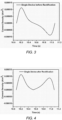
- triboelectric generator shown in Figs. 1 and 2 will now be described in more detail with reference to the graphs in Figs. 3 to 8 .
- the graphs in Figs. 3 to 6 illustrate simulated current outputs through a 1 giga-ohm (G ⁇ ) load resistance, while Figs 7 and 8 illustrate experimental data obtained from tests on a triboelectric generator similar to the one shown in Fig. 1 .
- Figure 3 is a graph showing the simulated output current of the power generation module 111 of Fig. 2 during a single output cycle (i.e. a single contact and separation cycle), which produces a single positive peak and a single negative peak in the output current.
- Figure 4 is a graph showing the simulated output of the power generation module 111 after rectification using the rectifier 130.
- FIG. 5 is a graph showing the simulated rectified output current of the six power generation modules 111 in the triboelectric generator 100 of Fig. 1 , during a single rotation of the second body 120 relative to the first body 110.
- the current signals from each of the power generation modules 111 peak at different points in time, with a gradual shift in the peak positions corresponding to the different times at which each power generation module 111 comes into contact with one of the actuating elements 121.
- Figure 6 is a graph showing the overall current signal at the common output 140, which results from the addition of all of the rectified and phase-shifted outputs of the plurality of power generation modules 111.
- the final output is a high current output with relatively little variation in magnitude compared to conventional triboelectric generators, and may be referred to as a near-DC output current.
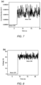
- FIG. 7 is a graph showing the output current measured at the common output 140 over time, comprising a first time interval in which the second body 120 is stationary (the time period labelled "Rotor OFF" in Fig. 7 ), followed by a second time interval in which the second body 120 is rotated relative to the first body 110 (the time period labelled "Rotor ON" in Fig.
- Fig. 7 is a graph showing the output voltage measured at the common output 140 over a similar time period, illustrating that near-DC output voltage is obtained.
- the data plotted in Fig. 7 was obtained during an experiment in which the rotor was turned on at about 7 seconds, whilst the data plotted in Fig. 8 was obtained during another experiment in which the rotor was turned on at about 8.5 seconds.
- a triboelectric generator similar to the one shown in Fig. 1 has demonstrated that the generator is capable of operating at a wide range of frequencies, including at least from 0.1 Hertz (Hz) up to 1000 Hz, and at a range of rotation speeds from 3 revolutions per minute (rpm) up to about 2000 rpm.
- the triboelectric generator has been demonstrated to produce an output voltage of around 120 V and a current density in the range of milliamps per metre squared (mA/m 2 ).
- the triboelectric generator 900 of the present embodiment comprises a first body 910, a second body 920, a plurality of power generating modules 911 and a plurality of actuating elements 921.
- each of the power generating modules 911 is connected to the common output 940 via a respective one of a plurality of rectifiers 930.
- the plurality of actuating elements 921 are arranged so as to come into contact with different ones of the power generation modules 911 at substantially the same time.
- the triboelectric generator 900 further comprises means 931 for delaying the power output of one power generation module relative to other ones of the power generation modules 911.
- the means 931 for delaying the power output may also be referred to as a delay unit, or a delay circuit.
- the delay circuit 931 may comprise one or more active electrical components which require electrical power to function, and the one or more active electrical components can be arranged to be powered from the common output. In this way, the delay circuit 931 can operate without the need for an external power supply.
- a plurality of delay units 931 can be configured to delay the power outputs of the plurality of power generation modules 911 by different amounts of time, so as to introduce a phase shift between the outputs of different power generation modules 911. Accordingly, the use of delay units 931 allows the electrical power generated by one of the power generation modules 911 to be supplied to the common output 940 at a different time to the electrical power generated by other ones of the power generation modules. In this embodiment a phase shift is introduced electrically via the delay units 931, as opposed to the embodiment shown in Fig. 1 , in which a phase shift is introduced mechanically by arranging the actuating elements 121 to make contact with the power generation modules 111 at different points in time.
- Fig. 9 illustrates a near-DC output current to be generated, similar to the example shown in Fig. 7 .
- Fig. 10 illustrates a simulated combined output current of the triboelectric generator 900 if the delay units 931 were omitted.
- a triboelectric generator converts rotary motion to electrical power.
- triboelectric generators may be configured to be driven by different types of motion.
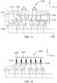
- a triboelectric generator configured to convert linear motion to electrical power is illustrated in cross-section, according to an embodiment of the present invention.
- the triboelectric generator 1100 comprises a first body 1110 and a second body 1120 arranged to move linearly relative to the first body 1110.
- the triboelectric generator 1100 is configured to convert relative linear motion of the first and second bodies 1110, 1120 to electrical power.
- each power generation module comprises a first power generation part 1111 disposed on the first body 1110 and a second power generation part 1121 disposed on the second body 1120.
- the second power generation part 1121 acts as the actuating element for the first power generation part 1111
- the first power generation part 1111 acts as the actuating element for the second power generation part 1121.
- Either one of the first and second power generation parts 1111, 1121 can comprise triboelectric material, and the other one of the first and second power generation parts 1111, 1121 comprises the other surface that is arranged to come into contact with the surface of the triboelectric material during relative movement of the first and second bodies 1110, 1120.
- Each power generation module further comprises an electrical connection 1131 configured to electrically connect the first power generation part 1111 to the second power generation part 1121.
- the triboelectric generator 1100 further comprises a plurality of rectifiers 1130 each connected to a respective one of the plurality of power generation modules. Each rectifier 1130 comprises a first input, a second input, a positive output and a negative output.
- the common output 1140 comprises a positive terminal and a negative terminal, and the first power generation part 1111 of one of the power generation modules is electrically connected to the first input of a respective one of the plurality of rectifiers 1130, the second power generation part 1121 of said one of the power generation modules is electrically connected to the second input of said one of the plurality of rectifiers 1130, the positive output of said one of the plurality of rectifiers 1130 is connected to the positive terminal, and the negative output of said one of the plurality of rectifiers 1130 is connected to the negative terminal.
- a rectified current is provided at the common output.
- a spacing between adjacent ones of the plurality of first power generation parts 1111, d 1 is different to a spacing between adjacent ones of the plurality of second power generation parts 1121.
- the spacing between adjacent ones of the plurality of first power generation parts 1111 increases from the right-hand side of the apparatus 1100 to the left-hand side, meaning that the distance d 1 varies for different pairs of adjacent first power generation parts 1111.
- the second power generation parts 1121 are spaced apart at regular intervals on the second body 1120. In this way, the second power generation parts 1121 come into contact with the first power generation parts 1111 at different times during relative linear movement of the first and second bodies 1110, 1120.
- the required phase shift is engineered by selecting appropriate spacings for the first and second power generation parts 1111, 1121.
- the spacing between the first power generation parts and the spacing between the second power generation parts may be the same, such that the plurality of power generation modules are triggered simultaneously, and delay circuits may be used to delay the output of each power generation module by a different amount to introduce the necessary phase shifts, as described above.
- Fig. 11 an opposite arrangement to the one shown in Fig. 11 may be used, wherein the plurality of first power generation parts 1111 are disposed at regular intervals on the first body 1110 and the plurality of second power generation parts 1121 are disposed at varying intervals on the second body 1120.
- the plurality of first power generation parts 1111 and the plurality of second power generation parts 1121 can both be spaced apart at regular intervals, with different pitches d 1 , d 2 being used for the first and second power generation parts 1111, 1121.
- a triboelectric generator is illustrated in which a plurality of power generation modules similar to the one shown in Fig. 2 are arranged to produce power during relative linear motion of first and second bodies 1210, 1220, according to an embodiment of the present invention.
- the triboelectric generator 1200 comprises a plurality of actuating elements 1221 disposed on the second body 1220, and a plurality of power generating modules 1211 disposed on the first body 1210.
- the plurality of power generation modules 1211 are spaced apart at regular intervals, and the pitch (distance between adjacent power generation modules 1211) is different to the pitch that is used for the plurality of actuating elements 1221.
- the actuating elements 1221 come into contact with the power generation modules 1211 at different times during relative linear movement of the first and second bodies 1210, 1220.
- the spacing between the power generation modules 1211 and the spacing between the actuating elements 1221 may be the same, such that the plurality of power generation modules 1211 are triggered simultaneously, and delay circuits may be used to delay the output of each power generation module 1211 by a different amount to introduce the necessary phase shifts, as described above.
- a triboelectric generator can be used to convert relative motion between two bodies into electrical power.
- the triboelectric generator may be coupled to an apparatus that comprises first and second parts arranged to move relative to one another during normal operation of the apparatus, for example machinery configured to produce linear and/or rotational motion, or layers of fabric in an item of clothing that are free to slide over one another.
- the triboelectric generator can be used to harvest electrical power from the relative movement of the first and second parts of the apparatus, by physically connecting the first and second bodies of the triboelectric generator to the first and second parts of the apparatus, respectively.
- the first and second bodies may comprise layers of fabric or other flexible material that can be incorporated into clothing.
Landscapes
- Rectifiers (AREA)
- Generation Of Surge Voltage And Current (AREA)
Claims (15)
- Triboelektrischer Generator (100; 900; 1200) zum Generieren elektrischer Leistung unter Verwendung des triboelektrischen Effekts, wobei der triboelektrische Generator Folgendes umfasst:einen ersten Körper (110; 910; 1210);einen zweiten Körper (120; 920; 1220), der relativ zu dem ersten Körper bewegbar ist;eine Vielzahl von Leistungsgenerierungsmodulen (111; 911; 1211), die an dem ersten Körper angeordnet ist, wobei jedes der Vielzahl von Leistungsgenerierungsmodulen elektrisch mit einem gemeinsamen Ausgang verbunden ist und Material umfasst, das in der Lage ist, durch den triboelektrischen Effekt elektrische Leistung zu generieren, wenn es mit einer anderen Fläche in Kontakt gebracht wird; undein oder mehrere Betätigungselemente (121; 921; 1221), die an dem zweiten Körper angeordnet sind,wobei die Vielzahl von Leistungsgenerierungsmodulen und das eine oder die mehreren Betätigungselemente so an dem ersten und dem zweiten Körper angeordnet sind, dass eine Relativbewegung des ersten und des zweiten Körpers bewirken kann, dass das eine oder die mehreren Betätigungselemente mit der Vielzahl von Leistungsgenerierungsmodulen in Kontakt kommen,wobei der Kontakt zwischen einem des einen oder der mehreren Betätigungselemente und einem der Leistungsgenerierungsmodule bewirkt, dass das Material des einen der Leistungsgenerierungsmodule mit der anderen Fläche in Kontakt gebracht wird, sodass elektrische Leistung generiert wird, undwobei der triboelektrische Generator derart konfiguriert ist, dass die Vielzahl von Leistungsgenerierungsmodulen während der Relativbewegung des ersten und des zweiten Körpers zu unterschiedlichen Zeitpunkten elektrische Leistung an den gemeinsamen Ausgang liefert,dadurch gekennzeichnet, dass jedes Leistungsgenerierungsmodul Folgendes umfasst:eine Leistungsgenerierungskomponente (203), die das Material umfasst, das in der Lage ist, durch den triboelektrischen Effekt elektrische Leistung zu generieren; undeine erste Kontaktfläche (201), die die andere Fläche umfasst, die so angeordnet ist, dass sie mit dem Material in Kontakt gebracht wird, wobei die erste Kontaktfläche von der Leistungsgenerierungskomponente um einen Abstand beabstandet ist, sodass, wenn die Leistungsgenerierungskomponente in einer Richtung auf die erste Kontaktfläche zu oder von ihr weg abgelenkt und anschließend gelöst wird, die Leistungsgenerierungskomponente schwingt und wiederholt Kontakt mit der ersten Kontaktfläche herstellt, wodurch elektrische Leistung generiert wird.
- Triboelektrischer Generator nach Anspruch 1, wobei das eine oder die mehreren Betätigungselemente so angeordnet sind, dass sie während der Relativbewegung des ersten und des zweiten Körpers zu unterschiedlichen Zeitpunkten mit den Leistungsgenerierungsmodulen in Kontakt kommen.
- Triboelektrischer Generator nach Anspruch 2, wobei die Relativbewegung eine relative Linearbewegung des ersten und des zweiten Körpers umfasst, das eine oder die mehreren Betätigungselemente eine Vielzahl von Betätigungselementen umfassen und sich ein Abstand zwischen benachbarten der Leistungsgenerierungsmodule von einem Abstand zwischen benachbarten der Vielzahl von Betätigungselementen unterscheidet, sodass die benachbarten Betätigungselemente die benachbarten Leistungsgenerierungsmodule während der relativen Linearbewegung zu unterschiedlichen Zeitpunkten berühren.
- Triboelektrischer Generator nach Anspruch 2, wobei die Relativbewegung eine Drehung des ersten Körpers relativ zu dem zweiten Körper umfasst, das eine oder die mehreren Betätigungselemente eine Vielzahl von Betätigungselementen umfassen und sich ein Winkelabstand zwischen benachbarten der Leistungsgenerierungsmodule von einem Winkelabstand zwischen benachbarten der Vielzahl von Betätigungselementen unterscheidet, sodass die benachbarten Betätigungselemente die benachbarten Leistungsgenerierungsmodule während der relativen Drehung des ersten und des zweiten Körpers zu unterschiedlichen Zeitpunkten berühren.
- Triboelektrischer Generator nach Anspruch 4, wobei der erste Körper den zweiten Körper zumindest teilweise umgibt, sodass sich der zweite Körper innerhalb des ersten Körpers dreht, und sich jedes der Vielzahl von Leistungsgenerierungsmodulen von dem ersten Körper nach innen in Richtung des zweiten Körpers erstreckt, oder
wobei der zweite Körper den ersten Körper zumindest teilweise umgibt, sodass sich der erste Körper innerhalb des zweiten Körpers dreht, und sich jedes der Vielzahl von Leistungsgenerierungsmodulen von dem ersten Körper nach außen in Richtung des zweiten Körpers erstreckt. - Triboelektrischer Generator nach einem der vorhergehenden Ansprüche, wobei die Vielzahl von Leistungsgenerierungsmodulen eine Vielzahl von ersten Leistungsgenerierungsmodulen umfasst und eines oder mehrere der Vielzahl von Betätigungselementen ein zweites Leistungsgenerierungsmodul umfassen, sodass, wenn eines der ersten Leistungsgenerierungsmodule durch das zweite Leistungsgenerierungsmodul betätigt wird, um elektrische Leistung zu erzeugen, das zweite Leistungsgenerierungsmodul gleichzeitig durch das eine der ersten Leistungsgenerierungsmodule betätigt wird, um zusätzliche elektrische Leistung zu erzeugen.
- Triboelektrischer Generator nach Anspruch 1, wobei die Leistungsgenerierungsmodule so angeordnet sind, dass sie im Wesentlichen gleichzeitig mit der anderen Fläche in Kontakt kommen, wobei der triboelektrische Generator ferner Folgendes umfasst:eine Einrichtung (931) zum Verzögern der Leistungsabgabe eines Leistungsgenerierungsmoduls im Verhältnis zu anderen der Leistungsgenerierungsmodule, sodass die durch das eine Leistungsgenerierungsmodul generierte elektrische Leistung zu einem anderen Zeitpunkt an den gemeinsamen Ausgang geliefert wird als die durch andere der Leistungsgenerierungsmodule generierte elektrische Leistung,wobei optional die Einrichtung zum Verzögern der Leistungsabgabe eine Verzögerungsschaltung umfasst, wobei die Verzögerungsschaltung optional eine oder mehrere aktive elektrische Komponenten umfasst, die so angeordnet sind, dass sie von dem gemeinsamen Ausgang mit Leistung versorgt werden.
- Triboelektrischer Generator nach einem der vorhergehenden Ansprüche, ferner umfassend einen oder mehrere Gleichrichter (130; 930), die dazu konfiguriert sind, einen durch jedes der Vielzahl von Leistungsgenerierungsmodulen generierten elektrischen Strom gleichzurichten und den gleichgerichteten elektrischen Strom an den gemeinsamen Ausgang zu liefern, und/oderwobei die erste Kontaktfläche ein anderes Material umfasst als die Leistungsgenerierungskomponente, und/oderwobei jedes Leistungsgenerierungsmodul ferner eine zweite Kontaktfläche (202) umfasst, die auf einer der ersten Kontaktfläche gegenüberliegenden Seite der Leistungsgenerierungskomponente angeordnet ist, sodass die Leistungsgenerierungskomponente während der Schwingung der Leistungsgenerierungskomponente abwechselnd die erste und die zweite Kontaktfläche berührt, und/oderwobei sich die Leistungsgenerierungskomponente und die erste Kontaktfläche von einer Fläche des ersten Körpers weg in Richtung des einen oder der mehreren Betätigungselemente erstrecken, wobei sich die Leistungsgenerierungskomponente weiter von dem ersten Körper weg erstreckt als die erste Kontaktfläche und ein Trennungsabstand zwischen dem ersten und dem zweiten Körper so festgelegt ist, dass während der Relativbewegung des ersten und des zweiten Körpers das eine oder die mehreren Betätigungselemente die Leistungsgenerierungskomponente, jedoch nicht die erste Kontaktfläche berühren, und/oderwobei die erste Kontaktfläche eine höhere Steifigkeit als die Leistungsgenerierungskomponente aufweist.
- Triboelektrischer Generator nach einem der vorhergehenden Ansprüche, wobei jedes Leistungsgenerierungsmodul Folgendes umfasst:eine erste (211) und eine zweite (212) Elektrode,wobei die Leistungsgenerierungskomponente und die erste Kontaktfläche zwischen der ersten und der zweiten Elektrode angeordnet sind, sodass die Schwingung der Leistungsgenerierungskomponente eine Potentialdifferenz zwischen der ersten und der zweiten Elektrode induziert, undwobei die erste und die zweite Elektrode mit dem gemeinsamen Ausgang verbunden sind.
- Triboelektrischer Generator nach Anspruch 9, umfassend:eine Vielzahl von Gleichrichtern, wobei jeder mit einem jeweiligen der Vielzahl von Leistungsgenerierungsmodulen verbunden ist, wobei jeder Gleichrichter einen ersten Eingang, einen zweiten Eingang, einen positiven Ausgang und einen negativen Ausgang umfasst,wobei der gemeinsame Ausgang einen positiven Anschluss und einen negativen Anschluss umfasst, undwobei die erste Elektrode eines der Leistungsgenerierungsmodule elektrisch mit dem ersten Eingang eines jeweiligen der Vielzahl von Gleichrichtern verbunden ist, die zweite Elektrode des einen der Leistungsgenerierungsmodule elektrisch mit dem zweiten Eingang des einen der Vielzahl von Gleichrichtern verbunden ist, der positive Ausgang des einen der Vielzahl von Gleichrichtern mit dem positiven Anschluss verbunden ist und der negative Ausgang des einen der Vielzahl von Gleichrichtern mit dem negativen Anschluss verbunden ist.
- Triboelektrischer Generator nach Anspruch 10, wobei die erste Kontaktfläche aus der ersten Elektrode besteht, oder
wobei die erste Kontaktfläche eine triboelektrische Schicht umfasst, die auf der ersten Elektrode angeordnet ist, sodass die Leistungsgenerierungskomponente während der Schwingung der Leistungsgenerierungskomponente wiederholt Kontakt mit der triboelektrischen Schicht herstellt. - Triboelektrischer Generator nach einem der Ansprüche 9 bis 11, wobei die Leistungsgenerierungskomponente als Materialplatte ausgebildet ist, die in der Lage ist, durch den triboelektrischen Effekt elektrische Leistung zu generieren, und die erste und die zweite Elektrode so angeordnet sind, dass sie zumindest einen Teil der Materialplatte überlappen.
- Vorrichtung, umfassend:ein erstes und ein zweites Teil, die so angeordnet sind, dass sie sich während des Normalbetriebs der Vorrichtung relativ zueinander bewegen; undeinen triboelektrischen Generator nach einem der vorhergehenden Ansprüche zur Gewinnung von elektrischer Leistung aus der Relativbewegung des ersten und des zweiten Teils der Vorrichtung,wobei der erste Körper des triboelektrischen Generators das erste Teil der Vorrichtung umfasst oder physisch mit diesem verbunden ist und der zweite Körper des triboelektrischen Generators das zweite Teil der Vorrichtung umfasst oder physisch mit diesem verbunden ist.
- Vorrichtung nach Anspruch 13, wobei die Vorrichtung dazu konfiguriert ist, an einem menschlichen oder tierischen Körper getragen zu werden, sodass eine Bewegung des menschlichen oder tierischen Körpers bewirkt, dass sich das erste und das zweite Teil relativ zueinander bewegen, wobei die Vorrichtung optional ein Kleidungsstück umfasst, und/oder
wobei das erste und das zweite Teil Materialschichten umfassen, die so angeordnet sind, dass sie übereinander gleiten. - Vorrichtung nach Anspruch 13, wobei die Vorrichtung eine Maschinerie umfasst, die dazu konfiguriert ist, eine lineare und/oder drehende Bewegung zu erzeugen.
Applications Claiming Priority (2)
| Application Number | Priority Date | Filing Date | Title |
|---|---|---|---|
| GBGB1819309.4A GB201819309D0 (en) | 2018-11-27 | 2018-11-27 | Triboelectric generator |
| PCT/GB2019/053344 WO2020109783A1 (en) | 2018-11-27 | 2019-11-27 | Triboelectric generator |
Publications (3)
| Publication Number | Publication Date |
|---|---|
| EP3888239A1 EP3888239A1 (de) | 2021-10-06 |
| EP3888239B1 true EP3888239B1 (de) | 2024-06-26 |
| EP3888239C0 EP3888239C0 (de) | 2024-06-26 |
Family
ID=65024463
Family Applications (1)
| Application Number | Title | Priority Date | Filing Date |
|---|---|---|---|
| EP19816849.4A Active EP3888239B1 (de) | 2018-11-27 | 2019-11-27 | Triboelektrischer generator |
Country Status (6)
| Country | Link |
|---|---|
| US (1) | US11881793B2 (de) |
| EP (1) | EP3888239B1 (de) |
| ES (1) | ES2986925T3 (de) |
| GB (1) | GB201819309D0 (de) |
| PL (1) | PL3888239T3 (de) |
| WO (1) | WO2020109783A1 (de) |
Families Citing this family (1)
| Publication number | Priority date | Publication date | Assignee | Title |
|---|---|---|---|---|
| US20200070664A1 (en) * | 2017-10-13 | 2020-03-05 | Esther IN | Method and apparatus for harvesting electric energy from air flow in a moving system |
Family Cites Families (6)
| Publication number | Priority date | Publication date | Assignee | Title |
|---|---|---|---|---|
| JP3865157B2 (ja) * | 1996-06-05 | 2007-01-10 | 株式会社デンソー | 車両用交流発電機 |
| US9444031B2 (en) * | 2013-06-28 | 2016-09-13 | Samsung Electronics Co., Ltd. | Energy harvester using mass and mobile device including the energy harvester |
| WO2017041736A1 (zh) * | 2015-09-11 | 2017-03-16 | 纳智源科技(唐山)有限责任公司 | 摩擦发电机电极及其制备方法、发光鞋 |
| RU2719361C2 (ru) * | 2015-12-24 | 2020-04-17 | Конинклейке Филипс Н.В. | Система генерирования или преобразования мощности |
| CN105897036B (zh) * | 2016-05-18 | 2018-04-24 | 江苏大学 | 一种利用风能的摩擦静电发电机 |
| KR101720913B1 (ko) * | 2016-12-28 | 2017-03-29 | 전남대학교산학협력단 | 마찰전기 발생장치 |
-
2018
- 2018-11-27 GB GBGB1819309.4A patent/GB201819309D0/en not_active Ceased
-
2019
- 2019-11-27 WO PCT/GB2019/053344 patent/WO2020109783A1/en not_active Ceased
- 2019-11-27 US US17/296,483 patent/US11881793B2/en active Active
- 2019-11-27 EP EP19816849.4A patent/EP3888239B1/de active Active
- 2019-11-27 PL PL19816849.4T patent/PL3888239T3/pl unknown
- 2019-11-27 ES ES19816849T patent/ES2986925T3/es active Active
Also Published As
| Publication number | Publication date |
|---|---|
| WO2020109783A1 (en) | 2020-06-04 |
| GB201819309D0 (en) | 2019-01-09 |
| EP3888239C0 (de) | 2024-06-26 |
| EP3888239A1 (de) | 2021-10-06 |
| US11881793B2 (en) | 2024-01-23 |
| PL3888239T3 (pl) | 2024-12-02 |
| US20220052628A1 (en) | 2022-02-17 |
| ES2986925T3 (es) | 2024-11-13 |
Similar Documents
| Publication | Publication Date | Title |
|---|---|---|
| JP5800707B2 (ja) | 発電装置およびそれを備えた発電機器 | |
| EP3384590B1 (de) | Energieerzeugungssystem und -verfahren | |
| US10644615B2 (en) | Electrostatic induction generator | |
| US10734920B2 (en) | Electrical current waveform generator, actuator and generation method | |
| JP6799484B2 (ja) | 電気機械変換器およびその製造方法 | |
| KR20200083028A (ko) | 커패시터 구조를 이용한 마찰대전 발전기 | |
| EP3888239B1 (de) | Triboelektrischer generator | |
| Lee et al. | Bidirectional rotating direct-current triboelectric nanogenerator with self-adaptive mechanical switching for harvesting reciprocating motion | |
| CN113162460B (zh) | 一种静电式旋转、直线往复运动耦合能量收集器 | |
| JP6742084B2 (ja) | 静電誘導型発電器 | |
| JP6789156B2 (ja) | 電気機械変換器 | |
| EP3432462B1 (de) | Elektrostatisch-mechanischer wandler | |
| JP6792249B2 (ja) | 振動発電装置 | |
| JPH0744850B2 (ja) | 振動波モ−タ− | |
| JP5876179B2 (ja) | 発電装置 | |
| JP2004166442A (ja) | 発電装置および発電システム | |
| JP6062081B2 (ja) | 発電装置 | |
| JP2015164379A (ja) | 発電装置 | |
| JP7246333B2 (ja) | 発電装置、及び、整流回路 | |
| RU2264687C2 (ru) | Пьезогенератор | |
| HK1241147A1 (en) | Electrostatic induction generator | |
| CN117639546A (zh) | 一种混合发电机、发电方法及监测方法 | |
| KR20220086206A (ko) | 웨어러블 디바이스에 사용가능한 마찰전기 에너지 저장소자 | |
| HK1241147B (zh) | 静电感应型发电器 |
Legal Events
| Date | Code | Title | Description |
|---|---|---|---|
| STAA | Information on the status of an ep patent application or granted ep patent |
Free format text: STATUS: UNKNOWN |
|
| STAA | Information on the status of an ep patent application or granted ep patent |
Free format text: STATUS: THE INTERNATIONAL PUBLICATION HAS BEEN MADE |
|
| PUAI | Public reference made under article 153(3) epc to a published international application that has entered the european phase |
Free format text: ORIGINAL CODE: 0009012 |
|
| STAA | Information on the status of an ep patent application or granted ep patent |
Free format text: STATUS: REQUEST FOR EXAMINATION WAS MADE |
|
| 17P | Request for examination filed |
Effective date: 20210625 |
|
| AK | Designated contracting states |
Kind code of ref document: A1 Designated state(s): AL AT BE BG CH CY CZ DE DK EE ES FI FR GB GR HR HU IE IS IT LI LT LU LV MC MK MT NL NO PL PT RO RS SE SI SK SM TR |
|
| DAV | Request for validation of the european patent (deleted) | ||
| DAX | Request for extension of the european patent (deleted) | ||
| GRAP | Despatch of communication of intention to grant a patent |
Free format text: ORIGINAL CODE: EPIDOSNIGR1 |
|
| STAA | Information on the status of an ep patent application or granted ep patent |
Free format text: STATUS: GRANT OF PATENT IS INTENDED |
|
| INTG | Intention to grant announced |
Effective date: 20240412 |
|
| GRAS | Grant fee paid |
Free format text: ORIGINAL CODE: EPIDOSNIGR3 |
|
| GRAA | (expected) grant |
Free format text: ORIGINAL CODE: 0009210 |
|
| STAA | Information on the status of an ep patent application or granted ep patent |
Free format text: STATUS: THE PATENT HAS BEEN GRANTED |
|
| AK | Designated contracting states |
Kind code of ref document: B1 Designated state(s): AL AT BE BG CH CY CZ DE DK EE ES FI FR GB GR HR HU IE IS IT LI LT LU LV MC MK MT NL NO PL PT RO RS SE SI SK SM TR |
|
| REG | Reference to a national code |
Ref country code: GB Ref legal event code: FG4D |
|
| REG | Reference to a national code |
Ref country code: CH Ref legal event code: EP |
|
| REG | Reference to a national code |
Ref country code: DE Ref legal event code: R096 Ref document number: 602019054313 Country of ref document: DE |
|
| U01 | Request for unitary effect filed |
Effective date: 20240726 |
|
| U07 | Unitary effect registered |
Designated state(s): AT BE BG DE DK EE FI FR IT LT LU LV MT NL PT SE SI Effective date: 20240806 |
|
| PG25 | Lapsed in a contracting state [announced via postgrant information from national office to epo] |
Ref country code: HR Free format text: LAPSE BECAUSE OF FAILURE TO SUBMIT A TRANSLATION OF THE DESCRIPTION OR TO PAY THE FEE WITHIN THE PRESCRIBED TIME-LIMIT Effective date: 20240626 |
|
| PG25 | Lapsed in a contracting state [announced via postgrant information from national office to epo] |
Ref country code: GR Free format text: LAPSE BECAUSE OF FAILURE TO SUBMIT A TRANSLATION OF THE DESCRIPTION OR TO PAY THE FEE WITHIN THE PRESCRIBED TIME-LIMIT Effective date: 20240927 |
|
| PG25 | Lapsed in a contracting state [announced via postgrant information from national office to epo] |
Ref country code: NO Free format text: LAPSE BECAUSE OF FAILURE TO SUBMIT A TRANSLATION OF THE DESCRIPTION OR TO PAY THE FEE WITHIN THE PRESCRIBED TIME-LIMIT Effective date: 20240926 Ref country code: HR Free format text: LAPSE BECAUSE OF FAILURE TO SUBMIT A TRANSLATION OF THE DESCRIPTION OR TO PAY THE FEE WITHIN THE PRESCRIBED TIME-LIMIT Effective date: 20240626 Ref country code: GR Free format text: LAPSE BECAUSE OF FAILURE TO SUBMIT A TRANSLATION OF THE DESCRIPTION OR TO PAY THE FEE WITHIN THE PRESCRIBED TIME-LIMIT Effective date: 20240927 Ref country code: RS Free format text: LAPSE BECAUSE OF FAILURE TO SUBMIT A TRANSLATION OF THE DESCRIPTION OR TO PAY THE FEE WITHIN THE PRESCRIBED TIME-LIMIT Effective date: 20240926 |
|
| REG | Reference to a national code |
Ref country code: ES Ref legal event code: FG2A Ref document number: 2986925 Country of ref document: ES Kind code of ref document: T3 Effective date: 20241113 |
|
| U20 | Renewal fee for the european patent with unitary effect paid |
Year of fee payment: 6 Effective date: 20241125 |
|
| PG25 | Lapsed in a contracting state [announced via postgrant information from national office to epo] |
Ref country code: IS Free format text: LAPSE BECAUSE OF FAILURE TO SUBMIT A TRANSLATION OF THE DESCRIPTION OR TO PAY THE FEE WITHIN THE PRESCRIBED TIME-LIMIT Effective date: 20241026 |
|
| PG25 | Lapsed in a contracting state [announced via postgrant information from national office to epo] |
Ref country code: CZ Free format text: LAPSE BECAUSE OF FAILURE TO SUBMIT A TRANSLATION OF THE DESCRIPTION OR TO PAY THE FEE WITHIN THE PRESCRIBED TIME-LIMIT Effective date: 20240626 |
|
| PG25 | Lapsed in a contracting state [announced via postgrant information from national office to epo] |
Ref country code: RO Free format text: LAPSE BECAUSE OF FAILURE TO SUBMIT A TRANSLATION OF THE DESCRIPTION OR TO PAY THE FEE WITHIN THE PRESCRIBED TIME-LIMIT Effective date: 20240626 Ref country code: SK Free format text: LAPSE BECAUSE OF FAILURE TO SUBMIT A TRANSLATION OF THE DESCRIPTION OR TO PAY THE FEE WITHIN THE PRESCRIBED TIME-LIMIT Effective date: 20240626 |
|
| PG25 | Lapsed in a contracting state [announced via postgrant information from national office to epo] |
Ref country code: SM Free format text: LAPSE BECAUSE OF FAILURE TO SUBMIT A TRANSLATION OF THE DESCRIPTION OR TO PAY THE FEE WITHIN THE PRESCRIBED TIME-LIMIT Effective date: 20240626 |
|
| PG25 | Lapsed in a contracting state [announced via postgrant information from national office to epo] |
Ref country code: SM Free format text: LAPSE BECAUSE OF FAILURE TO SUBMIT A TRANSLATION OF THE DESCRIPTION OR TO PAY THE FEE WITHIN THE PRESCRIBED TIME-LIMIT Effective date: 20240626 Ref country code: SK Free format text: LAPSE BECAUSE OF FAILURE TO SUBMIT A TRANSLATION OF THE DESCRIPTION OR TO PAY THE FEE WITHIN THE PRESCRIBED TIME-LIMIT Effective date: 20240626 Ref country code: RO Free format text: LAPSE BECAUSE OF FAILURE TO SUBMIT A TRANSLATION OF THE DESCRIPTION OR TO PAY THE FEE WITHIN THE PRESCRIBED TIME-LIMIT Effective date: 20240626 Ref country code: IS Free format text: LAPSE BECAUSE OF FAILURE TO SUBMIT A TRANSLATION OF THE DESCRIPTION OR TO PAY THE FEE WITHIN THE PRESCRIBED TIME-LIMIT Effective date: 20241026 Ref country code: CZ Free format text: LAPSE BECAUSE OF FAILURE TO SUBMIT A TRANSLATION OF THE DESCRIPTION OR TO PAY THE FEE WITHIN THE PRESCRIBED TIME-LIMIT Effective date: 20240626 |
|
| PLBE | No opposition filed within time limit |
Free format text: ORIGINAL CODE: 0009261 |
|
| STAA | Information on the status of an ep patent application or granted ep patent |
Free format text: STATUS: NO OPPOSITION FILED WITHIN TIME LIMIT |
|
| 26N | No opposition filed |
Effective date: 20250327 |
|
| REG | Reference to a national code |
Ref country code: CH Ref legal event code: PL |
|
| PG25 | Lapsed in a contracting state [announced via postgrant information from national office to epo] |
Ref country code: MC Free format text: LAPSE BECAUSE OF FAILURE TO SUBMIT A TRANSLATION OF THE DESCRIPTION OR TO PAY THE FEE WITHIN THE PRESCRIBED TIME-LIMIT Effective date: 20240626 |
|
| REG | Reference to a national code |
Ref country code: CH Ref legal event code: PL |
|
| PG25 | Lapsed in a contracting state [announced via postgrant information from national office to epo] |
Ref country code: CH Free format text: LAPSE BECAUSE OF NON-PAYMENT OF DUE FEES Effective date: 20241130 |
|
| U20 | Renewal fee for the european patent with unitary effect paid |
Year of fee payment: 7 Effective date: 20251117 |
|
| PGFP | Annual fee paid to national office [announced via postgrant information from national office to epo] |
Ref country code: GB Payment date: 20251114 Year of fee payment: 7 |
|
| PGFP | Annual fee paid to national office [announced via postgrant information from national office to epo] |
Ref country code: IE Payment date: 20251120 Year of fee payment: 7 |
|
| PGFP | Annual fee paid to national office [announced via postgrant information from national office to epo] |
Ref country code: PL Payment date: 20251118 Year of fee payment: 7 |
|
| PGFP | Annual fee paid to national office [announced via postgrant information from national office to epo] |
Ref country code: ES Payment date: 20251216 Year of fee payment: 7 |