EP3888077B1 - Dynamisch einstellbares anzeigesystem und verfahren zur dynamischen einstellung einer anzeige - Google Patents
Dynamisch einstellbares anzeigesystem und verfahren zur dynamischen einstellung einer anzeige Download PDFInfo
- Publication number
- EP3888077B1 EP3888077B1 EP19818406.1A EP19818406A EP3888077B1 EP 3888077 B1 EP3888077 B1 EP 3888077B1 EP 19818406 A EP19818406 A EP 19818406A EP 3888077 B1 EP3888077 B1 EP 3888077B1
- Authority
- EP
- European Patent Office
- Prior art keywords
- mol
- flexible display
- display
- glass substrate
- bending
- Prior art date
- Legal status (The legal status is an assumption and is not a legal conclusion. Google has not performed a legal analysis and makes no representation as to the accuracy of the status listed.)
- Active
Links
Images


Classifications
-
- G—PHYSICS
- G09—EDUCATION; CRYPTOGRAPHY; DISPLAY; ADVERTISING; SEALS
- G09G—ARRANGEMENTS OR CIRCUITS FOR CONTROL OF INDICATING DEVICES USING STATIC MEANS TO PRESENT VARIABLE INFORMATION
- G09G3/00—Control arrangements or circuits, of interest only in connection with visual indicators other than cathode-ray tubes
- G09G3/03—Control arrangements or circuits, of interest only in connection with visual indicators other than cathode-ray tubes specially adapted for displays having non-planar surfaces, e.g. curved displays
-
- B—PERFORMING OPERATIONS; TRANSPORTING
- B60—VEHICLES IN GENERAL
- B60K—ARRANGEMENT OR MOUNTING OF PROPULSION UNITS OR OF TRANSMISSIONS IN VEHICLES; ARRANGEMENT OR MOUNTING OF PLURAL DIVERSE PRIME-MOVERS IN VEHICLES; AUXILIARY DRIVES FOR VEHICLES; INSTRUMENTATION OR DASHBOARDS FOR VEHICLES; ARRANGEMENTS IN CONNECTION WITH COOLING, AIR INTAKE, GAS EXHAUST OR FUEL SUPPLY OF PROPULSION UNITS IN VEHICLES
- B60K35/00—Instruments specially adapted for vehicles; Arrangement of instruments in or on vehicles
- B60K35/20—Output arrangements, i.e. from vehicle to user, associated with vehicle functions or specially adapted therefor
- B60K35/21—Output arrangements, i.e. from vehicle to user, associated with vehicle functions or specially adapted therefor using visual output, e.g. blinking lights or matrix displays
- B60K35/22—Display screens
- B60K35/223—Flexible displays
-
- B—PERFORMING OPERATIONS; TRANSPORTING
- B60—VEHICLES IN GENERAL
- B60K—ARRANGEMENT OR MOUNTING OF PROPULSION UNITS OR OF TRANSMISSIONS IN VEHICLES; ARRANGEMENT OR MOUNTING OF PLURAL DIVERSE PRIME-MOVERS IN VEHICLES; AUXILIARY DRIVES FOR VEHICLES; INSTRUMENTATION OR DASHBOARDS FOR VEHICLES; ARRANGEMENTS IN CONNECTION WITH COOLING, AIR INTAKE, GAS EXHAUST OR FUEL SUPPLY OF PROPULSION UNITS IN VEHICLES
- B60K35/00—Instruments specially adapted for vehicles; Arrangement of instruments in or on vehicles
- B60K35/55—Instruments with parts that can change their shape or position to configure an active screen, e.g. by folding or by rolling
-
- G—PHYSICS
- G09—EDUCATION; CRYPTOGRAPHY; DISPLAY; ADVERTISING; SEALS
- G09G—ARRANGEMENTS OR CIRCUITS FOR CONTROL OF INDICATING DEVICES USING STATIC MEANS TO PRESENT VARIABLE INFORMATION
- G09G3/00—Control arrangements or circuits, of interest only in connection with visual indicators other than cathode-ray tubes
- G09G3/03—Control arrangements or circuits, of interest only in connection with visual indicators other than cathode-ray tubes specially adapted for displays having non-planar surfaces, e.g. curved displays
- G09G3/035—Control arrangements or circuits, of interest only in connection with visual indicators other than cathode-ray tubes specially adapted for displays having non-planar surfaces, e.g. curved displays for flexible display surfaces
-
- G—PHYSICS
- G09—EDUCATION; CRYPTOGRAPHY; DISPLAY; ADVERTISING; SEALS
- G09G—ARRANGEMENTS OR CIRCUITS FOR CONTROL OF INDICATING DEVICES USING STATIC MEANS TO PRESENT VARIABLE INFORMATION
- G09G3/00—Control arrangements or circuits, of interest only in connection with visual indicators other than cathode-ray tubes
- G09G3/20—Control arrangements or circuits, of interest only in connection with visual indicators other than cathode-ray tubes for presentation of an assembly of a number of characters, e.g. a page, by composing the assembly by combination of individual elements arranged in a matrix no fixed position being assigned to or needed to be assigned to the individual characters or partial characters
- G09G3/22—Control arrangements or circuits, of interest only in connection with visual indicators other than cathode-ray tubes for presentation of an assembly of a number of characters, e.g. a page, by composing the assembly by combination of individual elements arranged in a matrix no fixed position being assigned to or needed to be assigned to the individual characters or partial characters using controlled light sources
- G09G3/30—Control arrangements or circuits, of interest only in connection with visual indicators other than cathode-ray tubes for presentation of an assembly of a number of characters, e.g. a page, by composing the assembly by combination of individual elements arranged in a matrix no fixed position being assigned to or needed to be assigned to the individual characters or partial characters using controlled light sources using electroluminescent panels
- G09G3/32—Control arrangements or circuits, of interest only in connection with visual indicators other than cathode-ray tubes for presentation of an assembly of a number of characters, e.g. a page, by composing the assembly by combination of individual elements arranged in a matrix no fixed position being assigned to or needed to be assigned to the individual characters or partial characters using controlled light sources using electroluminescent panels semiconductive, e.g. using light-emitting diodes [LED]
- G09G3/3208—Control arrangements or circuits, of interest only in connection with visual indicators other than cathode-ray tubes for presentation of an assembly of a number of characters, e.g. a page, by composing the assembly by combination of individual elements arranged in a matrix no fixed position being assigned to or needed to be assigned to the individual characters or partial characters using controlled light sources using electroluminescent panels semiconductive, e.g. using light-emitting diodes [LED] organic, e.g. using organic light-emitting diodes [OLED]
-
- B—PERFORMING OPERATIONS; TRANSPORTING
- B60—VEHICLES IN GENERAL
- B60K—ARRANGEMENT OR MOUNTING OF PROPULSION UNITS OR OF TRANSMISSIONS IN VEHICLES; ARRANGEMENT OR MOUNTING OF PLURAL DIVERSE PRIME-MOVERS IN VEHICLES; AUXILIARY DRIVES FOR VEHICLES; INSTRUMENTATION OR DASHBOARDS FOR VEHICLES; ARRANGEMENTS IN CONNECTION WITH COOLING, AIR INTAKE, GAS EXHAUST OR FUEL SUPPLY OF PROPULSION UNITS IN VEHICLES
- B60K2360/00—Indexing scheme associated with groups B60K35/00 or B60K37/00 relating to details of instruments or dashboards
- B60K2360/60—Structural details of dashboards or instruments
- B60K2360/68—Features of instruments
- B60K2360/691—Housings
-
- B—PERFORMING OPERATIONS; TRANSPORTING
- B60—VEHICLES IN GENERAL
- B60K—ARRANGEMENT OR MOUNTING OF PROPULSION UNITS OR OF TRANSMISSIONS IN VEHICLES; ARRANGEMENT OR MOUNTING OF PLURAL DIVERSE PRIME-MOVERS IN VEHICLES; AUXILIARY DRIVES FOR VEHICLES; INSTRUMENTATION OR DASHBOARDS FOR VEHICLES; ARRANGEMENTS IN CONNECTION WITH COOLING, AIR INTAKE, GAS EXHAUST OR FUEL SUPPLY OF PROPULSION UNITS IN VEHICLES
- B60K2360/00—Indexing scheme associated with groups B60K35/00 or B60K37/00 relating to details of instruments or dashboards
- B60K2360/741—Instruments adapted for user detection
-
- B—PERFORMING OPERATIONS; TRANSPORTING
- B60—VEHICLES IN GENERAL
- B60K—ARRANGEMENT OR MOUNTING OF PROPULSION UNITS OR OF TRANSMISSIONS IN VEHICLES; ARRANGEMENT OR MOUNTING OF PLURAL DIVERSE PRIME-MOVERS IN VEHICLES; AUXILIARY DRIVES FOR VEHICLES; INSTRUMENTATION OR DASHBOARDS FOR VEHICLES; ARRANGEMENTS IN CONNECTION WITH COOLING, AIR INTAKE, GAS EXHAUST OR FUEL SUPPLY OF PROPULSION UNITS IN VEHICLES
- B60K35/00—Instruments specially adapted for vehicles; Arrangement of instruments in or on vehicles
- B60K35/40—Instruments specially adapted for improving the visibility thereof to the user, e.g. fogging prevention or anti-reflection arrangements
- B60K35/415—Glare prevention
-
- B—PERFORMING OPERATIONS; TRANSPORTING
- B60—VEHICLES IN GENERAL
- B60K—ARRANGEMENT OR MOUNTING OF PROPULSION UNITS OR OF TRANSMISSIONS IN VEHICLES; ARRANGEMENT OR MOUNTING OF PLURAL DIVERSE PRIME-MOVERS IN VEHICLES; AUXILIARY DRIVES FOR VEHICLES; INSTRUMENTATION OR DASHBOARDS FOR VEHICLES; ARRANGEMENTS IN CONNECTION WITH COOLING, AIR INTAKE, GAS EXHAUST OR FUEL SUPPLY OF PROPULSION UNITS IN VEHICLES
- B60K35/00—Instruments specially adapted for vehicles; Arrangement of instruments in or on vehicles
- B60K35/65—Instruments specially adapted for specific vehicle types or users, e.g. for left- or right-hand drive
-
- G—PHYSICS
- G09—EDUCATION; CRYPTOGRAPHY; DISPLAY; ADVERTISING; SEALS
- G09G—ARRANGEMENTS OR CIRCUITS FOR CONTROL OF INDICATING DEVICES USING STATIC MEANS TO PRESENT VARIABLE INFORMATION
- G09G2360/00—Aspects of the architecture of display systems
- G09G2360/14—Detecting light within display terminals, e.g. using a single or a plurality of photosensors
- G09G2360/144—Detecting light within display terminals, e.g. using a single or a plurality of photosensors the light being ambient light
-
- G—PHYSICS
- G09—EDUCATION; CRYPTOGRAPHY; DISPLAY; ADVERTISING; SEALS
- G09G—ARRANGEMENTS OR CIRCUITS FOR CONTROL OF INDICATING DEVICES USING STATIC MEANS TO PRESENT VARIABLE INFORMATION
- G09G2380/00—Specific applications
- G09G2380/02—Flexible displays
-
- G—PHYSICS
- G09—EDUCATION; CRYPTOGRAPHY; DISPLAY; ADVERTISING; SEALS
- G09G—ARRANGEMENTS OR CIRCUITS FOR CONTROL OF INDICATING DEVICES USING STATIC MEANS TO PRESENT VARIABLE INFORMATION
- G09G2380/00—Specific applications
- G09G2380/10—Automotive applications
Definitions
- Embodiments described herein generally relate to systems and methods for adjusting a display. Specifically, embodiments described herein relate to display systems that are dynamically adjustable in response to ambient lighting conditions.
- Electronic displays are commonly used in various applications including in televisions, computers, electronic tablets, cell phones, vehicle displays, automated teller machines, self-checkout stations at grocery stores or restaurants, check-in stations at hotels or airports, among numerous other applications.
- the media displayed on these electronic displays can become difficult to see depending upon the ambient lighting conditions. For example, it can become difficult for a driver of a vehicle to see a vehicle display while driving in an area with bright light. A vehicle passenger may also have difficulty viewing an electronic display if the ambient light is too bright. The inability to view a vehicle display or other electronic display can be frustrating and inconvenient, and the user may be without remedy.
- Document CN108228070 discloses a flexible display device which is configured to automatically bend in response to detecting a request for starting an input application, and to spit the screen in an area for inputting text and an area for displaying. An optimal angle at which the display is controlled to be bent is determined in response to detected ambient light conditions.
- Document US2013/271352 discloses a configuration with plurality of photodetectors positioned on the boundary of a flexible display to reliably sense ambient light.
- Document US2018/188869 discloses a flexible display integrated on a dashboard of a vehicle, and provides an example of a flexible display realized on a cold-bent glass substrate.
- Document US2014/204509 discloses a flexible display device including a display unit on a flexible substrate, a deformation member and an ambient light sensor, the display device being configured to e.g. bend a left corner of the flexible display upon detecting that external light arrives from a left direction or to bend a right corner of the flexible display upon detecting that external light arrives from a right direction.
- Electronic displays are often used outdoors or in other areas of bright light.
- Bright light from a light source such as the sun, street lights, or the like can make it difficult to view media displayed on the electronic display.
- the bright ambient light may wash out the display and/or may produce a glare.
- a user may be unable to view the media displayed on the electronic display or may only be able to view the media partially.
- the user may have to manually adjust the position of the display or may have to move to a different location. Manually adjusting the position of the display can be inconvenient and troublesome for the user.
- the user may be unable to reposition the display or move the display to improve visibility of the media thereon.
- the display may be fixed in position on the vehicle so that it cannot be adjusted.
- the user may simply be unable to see the electronic display until the ambient lighting conditions change. This may be particularly problematic when driving a vehicle, as the electronic display in the vehicle may provide important information such as navigation information, traffic information, and vehicle systems information. It may be frustrating and inconvenient for the user to be unable to interact efficiently with the display and view important information.
- Embodiments herein relate to display systems that are dynamically adjustable in response to ambient lighting conditions.
- the display systems include a flexible display capable of dynamically bending in a reversible manner.
- the flexible display may include a glass substrate.
- the flexible display includes a cold-bent glass substrate.
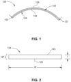
- FIG. 1 illustrates a flexible display 120 including a glass substrate 124 and a display module 126 according to some embodiments.
- Glass substrate 124 may be disposed on a top, user-facing surface of display module 126.
- glass substrate 124 may be a cover glass substrate.
- top surface or topmost surface and “bottom surface” or “bottommost surface” reference the top and bottom surface of a layer, component, or article as is would be oriented during its normal and intended use with the top surface being the user-facing surface.
- the "top surface" of an article, layer, or component refers to the top surface of that article, layer, or component as it would be oriented when the electronic display is being viewed through the article, component, or layer.
- glass substrate is used in its broadest sense to include any object made wholly or partly of glass.
- Glass substrates include laminates of glass and non-glass materials, laminates of glass and crystalline materials, and glass-ceramics (including an amorphous phase and a crystalline phase).
- the glass substrate may be transparent or opaque.
- the glass substrate may include a colorant that provides a specific color.
- cold-bent refers to curving the glass substrate at a cold-bend temperature which is less than the softening point of the glass (as described herein).
- cold-bendable refers to the capability of a glass substrate to be cold-bent.
- a feature of a cold-bent glass substrate is asymmetric surface compressive stress between the first major surface 123 and the second major surface 125.
- a minor surface 127 connects the first major surface 123 and the second major surface 125, as shown in FIG. 1 .
- second major surface 125 may be a user-facing, top surface of glass substrate 124.
- first major surface 123 may be a bottom surface of glass substrate 124.
- the respective compressive stresses in the first major surface 123 and the second major surface 125 of the glass substrate 124 are substantially equal.
- the first major surface 123 and the second major surface 125 exhibit no appreciable compressive stress, prior to cold-bending.
- the glass substrate 124 is strengthened (as described herein)
- the first major surface 123 and the second major surface 125 exhibit substantially equal compressive stress with respect to one another, prior to cold-bending.
- after cold-bending shown, for example, in FIGS.
- the compressive stress on the surface having a concave shape after bending increases.
- the compressive stress on the concave surface e.g., first major surface 123 is greater after cold-bending than before cold-bending.
- the cold-bending process increases the compressive stress of the glass substrate being shaped to compensate for tensile stresses imparted during bending and/or forming operations.
- the cold-bending process causes the concave surface (first major surface 123) to experience compressive stresses, while the surface forming a convex shape (i.e., the second major surface 125 in FIGS.
- the first major surface 123 and the second major surface 125 comprise a compressive stress that is substantially equal to one another prior to cold-bending, and thus the first major surface 123 can experience greater tensile stress during cold-bending without risking fracture. This allows for the strengthened glass substrate to conform to more tightly curved surfaces or shapes.
- the thickness of the glass substrate 124 is tailored to allow the glass substrate 124 to be more flexible to achieve the desired radius of curvature. Moreover, a thinner glass substrate 124 may deform more readily, which could potentially compensate for shape mismatches and gaps that may be created by the shape of the display module 126 (when curved). In one or more embodiments, a thin and strengthened glass substrate 124 exhibits greater flexibility especially during cold-bending. The greater flexibility of the glass substrates discussed herein may both allow for sufficient degrees of bending to be created via the air pressure-based bending processes as discussed herein and also for consistent bend formation without heating. In one or more embodiments, the glass substrate 124 and at least a portion of the display module 126 have substantially similar radii of curvature to provide a substantially uniform distance between the first major surface 123 and the display module 126 (which may be filled with an adhesive).
- the cold-bent glass substrate 124 (and optionally the curved display module 126) may have a compound curve including a major radius and a cross curvature.
- a complexly curved cold-bent glass substrate 124 (and optionally the curved display module) according to one or more embodiments may have a distinct radius of curvature in two independent directions.
- the complexly curved cold-bent glass substrate 124 may thus be characterized as having "cross curvature," where the cold-bent glass substrate (and optionally the curved display module) are curved along an axis (i.e., a first axis) that is parallel to a given dimension and also curved along an axis (i.e., a second axis) that is perpendicular to the same dimension.
- the curvature of the cold-bent glass substrate (and optionally the curved display module) can be even more complex when a significant minimum radius is combined with a significant cross curvature, and/or depth of bend.
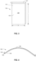
- the glass substrate 124 has a thickness (t) that is substantially constant and is defined as a distance between the first major surface 123 and the second major surface 125.
- the thickness (t) as used herein refers to the maximum thickness of the glass substrate 124.
- the glass substrate 124 includes a width (W) defined as a first maximum dimension of one of the first or second major surfaces orthogonal to the thickness (t), and a length (L) defined as a second maximum dimension of one of the first or second surfaces orthogonal to both the thickness and the width.
- W width
- L length
- the dimensions discussed herein may be average dimensions.
- the glass substrate 124 has a thickness (t) that is about 1.5 mm (millimeters) or less.
- the thickness may be in a range from about 0.01 mm to about 1.5 mm, 0.02 mm to about 1.5 mm, 0.03 mm to about 1.5 mm, 0.04 mm to about 1.5 mm, 0.05 mm to about 1.5 mm, 0.06 mm to about 1.5 mm, 0.07 mm to about 1.5 mm, 0.08 mm to about 1.5 mm, 0.09 mm to about 1.5 mm, 0.1 mm to about 1.5 mm, from about 0.15 mm to about 1.5 mm, from about 0.2 mm to about 1.5 mm, from about 0.25 mm to about 1.5 mm, from about 0.3 mm to about 1.5 mm, from about 0.35 mm to about 1.5 mm, from about 0.4 mm to about 1.5 mm, from about 0.45 mm to about 1.5 mm, from about 0.5 mm to about 1.5 mm, from about 0.55 mm to about 1.5 mm,
- the glass substrate 124 has a width (W) in a range from about 5 cm (centimeters) to about 250 cm, from about 10 cm to about 250 cm, from about 15 cm to about 250 cm, from about 20 cm to about 250 cm, from about 25 cm to about 250 cm, from about 30 cm to about 250 cm, from about 35 cm to about 250 cm, from about 40 cm to about 250 cm, from about 45 cm to about 250 cm, from about 50 cm to about 250 cm, from about 55 cm to about 250 cm, from about 60 cm to about 250 cm, from about 65 cm to about 250 cm, from about 70 cm to about 250 cm, from about 75 cm to about 250 cm, from about 80 cm to about 250 cm, from about 85 cm to about 250 cm, from about 90 cm to about 250 cm, from about 95 cm to about 250 cm, from about 100 cm to about 250 cm, from about 110 cm to about 250 cm, from about 120 cm to about 250 cm, from about 130 cm to about 250 cm, from about 140 cm to about 250 cm, from about 150 cm to about 250 cm, from
- the glass substrate has a length (L) in a range from about 5 cm to about 250 cm, from about 10 cm to about 250 cm, from about 15 cm to about 250 cm, from about 20 cm to about 250 cm, from about 25 cm to about 250 cm, from about 30 cm to about 250 cm, from about 35 cm to about 250 cm, from about 40 cm to about 250 cm, from about 45 cm to about 250 cm, from about 50 cm to about 250 cm, from about 55 cm to about 250 cm, from about 60 cm to about 250 cm, from about 65 cm to about 250 cm, from about 70 cm to about 250 cm, from about 75 cm to about 250 cm, from about 80 cm to about 250 cm, from about 85 cm to about 250 cm, from about 90 cm to about 250 cm, from about 95 cm to about 250 cm, from about 100 cm to about 250 cm, from about 110 cm to about 250 cm, from about 120 cm to about 250 cm, from about 130 cm to about 250 cm, from about 140 cm to about 250 cm, from about 150 cm to about 250 cm, from about 5 cm to about 240 cm
- the glass substrate 124 may be strengthened. In one or more embodiments, the glass substrate 124 may be strengthened to include compressive stress that extends from a surface to a depth of compression (DOC). The compressive stress regions are balanced by a central portion exhibiting a tensile stress. At the DOC, the stress crosses from a compressive stress to a tensile stress. The compressive stress and the tensile stress are provided herein as absolute values.
- DOC depth of compression
- the glass substrate 124 may be strengthened mechanically by utilizing a mismatch of the coefficient of thermal expansion between portions of the article to create a compressive stress region and a central region exhibiting a tensile stress. In some embodiments, the glass substrate 124 may be strengthened thermally by heating the glass to a temperature above the glass transition point and then rapidly quenching.
- the glass substrate 124 may be chemically strengthened by ion exchange.
- ions at or near the surface of the glass substrate are replaced by - or exchanged with - larger ions having the same valence or oxidation state.
- ions in the surface layer of the article and the larger ions are monovalent alkali metal cations, such as Li+, Na+, K+, Rb+, and Cs+.
- monovalent cations in the surface layer may be replaced with monovalent cations other than alkali metal cations, such as Ag+ or the like.
- the monovalent ions (or cations) exchanged into the glass substrate generate a stress.
- Ion exchange processes are typically carried out by immersing a glass substrate 124 in a molten salt bath (or two or more molten salt baths) containing the larger ions to be exchanged with the smaller ions in the glass substrate. It should be noted that aqueous salt baths may also be utilized. In addition, the composition of the bath(s) may include more than one type of larger ion (e.g., Na+ and K+) or a single larger ion.
- parameters for the ion exchange process including, but not limited to, bath composition and temperature, immersion time, the number of immersions of the glass substrate in a salt bath (or baths), use of multiple salt baths, additional steps such as annealing, washing, and the like, are generally determined by the composition of the glass substrate (including the structure of the article and any crystalline phases present) and the desired DOC and CS of the glass substrate that results from strengthening.
- Exemplary molten bath composition may include nitrates, sulfates, and chlorides of the larger alkali metal ion. Typical nitrates include KNO 3 , NaNO 3 , LiNO 3 , and combinations thereof.
- the temperature of the molten salt bath typically is in a range from about 380 °C up to about 500 °C, while immersion times range from about 15 minutes up to about 100 hours depending on glass substrate thickness, bath temperature and glass (or monovalent ion) diffusivity. However, temperatures and immersion times different from those described above may also be used.
- the glass substrates may be immersed in a molten salt bath of 100% NaNO 3 , 100% KNO 3 , or a combination of NaNO 3 and KNO 3 having a temperature from about 370 °C to about 480 °C.
- the glass substrate may be immersed in a molten mixed salt bath including from about 1% to about 99% KNO 3 and from about 1% to about 99% NaNO 3 .
- the glass substrate may be immersed in a second bath, after immersion in a first bath.
- the first and second baths may have different compositions and/or temperatures from one another. The immersion times in the first and second baths may vary. For example, immersion in the first bath may be longer than the immersion in the second bath.
- the glass substrate may be immersed in a molten, mixed salt bath including NaNO 3 and KNO 3 (e.g., 49%/51%, 50%/50%, 51%/49%) having a temperature less than about 420 °C (e.g., about 400 °C or about 380 °C) for less than about 5 hours, or even about 4 hours or less.
- a molten, mixed salt bath including NaNO 3 and KNO 3 (e.g., 49%/51%, 50%/50%, 51%/49%) having a temperature less than about 420 °C (e.g., about 400 °C or about 380 °C) for less than about 5 hours, or even about 4 hours or less.
- Ion exchange conditions can be tailored to provide a "spike” or to increase the slope of the stress profile at or near the surface of the resulting glass substrate.
- the spike may result in a greater surface CS value.
- This spike can be achieved by single bath or multiple baths, with the bath(s) having a single composition or mixed composition, due to the unique properties of the glass compositions used in the glass substrates described herein.
- the different monovalent ions may exchange to different depths within the glass substrate (and generate different magnitude stresses within the glass substrate at different depths).
- the resulting relative depths of the stress-generating ions can be determined and cause different characteristics of the stress profile.
- CS is measured using those means known in the art, such as by surface stress meter using commercially available instruments such as the FSM-6000 (FSM), manufactured by Orihara Industrial Co., Ltd. (Japan).
- FSM FSM-6000
- Surface stress measurements rely upon the accurate measurement of the stress optical coefficient (SOC), which is related to the birefringence of the glass.
- SOC in tum is measured by those methods that are known in the art, such as fiber and four point bend methods, both of which are described in ASTM standard C770-98 (2013), entitled “Standard Test Method for Measurement of Glass Stress-Optical Coefficient," the contents of which are incorporated herein by reference in their entirety, and a bulk cylinder method.
- CS may be the "maximum compressive stress" which is the highest compressive stress value measured within the compressive stress layer.
- the maximum compressive stress is located at the surface of the glass substrate. In other embodiments, the maximum compressive stress may occur at a depth below the surface, giving the compressive profile the appearance of a "buried peak.”
- DOC may be measured by FSM, by ASTM standard C1422/C1422M-15 entitled “Standard Specification for Chemically Strengthened Flat Glass,” or by a scattered light polariscope (SCALP) (such as the SCALP-04 scattered light polariscope available from Glasstress Ltd., located in Tallinn, Estonia), depending on the strengthening method and conditions.
- SCALP scattered light polariscope
- FSM or SCALP may be used depending on which ion is exchanged into the glass substrate.
- FSM is used to measure DOC.
- SCALP is used to measure DOC.
- the DOC is measured by SCALP, since it is believed the exchange depth of sodium indicates the DOC and the exchange depth of potassium ions indicates a change in the magnitude of the compressive stress (but not the change in stress from compressive to tensile); the exchange depth of potassium ions in such glass substrates is measured by FSM.
- Central tension or CT is the maximum tensile stress and is measured by SCALP.
- the glass substrate maybe strengthened to exhibit a DOC that is described a fraction of the thickness (t) of the glass substrate (as described herein).
- the DOC may be equal to or greater than about 0.05t, equal to or greater than about 0.1t, equal to or greater than about 0.11t, equal to or greater than about 0.12t, equal to or greater than about 0.13t, equal to or greater than about 0.14t, equal to or greater than about 0.15t, equal to or greater than about 0.16t, equal to or greater than about 0.17t, equal to or greater than about 0.18t, equal to or greater than about 0.19t, equal to or greater than about 0.2t, equal to or greater than about 0.21t.
- the DOC may be in a range from about 0.08t to about 0.25t, from about 0.09t to about 0.25t, from about 0.18t to about 0.25t, from about 0.11t to about 0.25t, from about 0.12t to about 0.25t, from about 0.13t to about 0.25t, from about 0.14t to about 0.25t, from about 0.15t to about 0.25t, from about 0.08t to about 0.24t, from about 0.08t to about 0.23t, from about 0.08t to about 0.22t, from about 0.08t to about 0.21t, from about 0.08t to about 0.2t, from about 0.08t to about 0.19t, from about 0.08t to about 0.18t, from about 0.08t to about 0.17t, from about 0.08t to about 0.16t, or from about 0.08t to about 0.15t.
- the DOC may be about 20 ⁇ m or less. In one or more embodiments, the DOC may be about 20 ⁇ m or greater, 30 ⁇ m or greater, or 40 ⁇ m or greater (e.g., from about 20 ⁇ m to about 300 ⁇ m, from about 25 ⁇ m to about 300 ⁇ m, from about 30 ⁇ m to about 300 ⁇ m, from about 35 ⁇ m to about 300 ⁇ m, from about 40 ⁇ m to about 300 ⁇ m, from about 50 ⁇ m to about 300 ⁇ m, from about 60 ⁇ m to about 300 ⁇ m, from about 70 ⁇ m to about 300 ⁇ m, from about 80 ⁇ m to about 300 ⁇ m, from about 90 ⁇ m to about 300 ⁇ m, from about 100 ⁇ m to about 300 ⁇ m, from about 110 ⁇ m to about 300 ⁇ m, from about 120 ⁇ m to about 300 ⁇ m, from about 140 ⁇ m to about 300 ⁇ m, from about 150 ⁇ m to about 300 ⁇ m, from about 20
- the strengthened glass substrate may have a CS (which may be found at the surface or a depth within the glass substrate) of about 200 MPa (megapascals) or greater, 300 MPa or greater, 400 MPa or greater, about 500 MPa or greater, about 600 MPa or greater, about 700 MPa or greater, about 800 MPa or greater, about 900 MPa or greater, about 930 MPa or greater, about 1000 MPa or greater, or about 1050 MPa or greater.
- CS which may be found at the surface or a depth within the glass substrate
- the strengthened glass substrate may have a CS (which may be found at the surface or a depth within the glass substrate) from about 200 MPa to about 1050 MPa, from about 250 MPa to about 1050 MPa, from about 300 MPa to about 1050 MPa, from about 350 MPa to about 1050 MPa, from about 400 MPa to about 1050 MPa, from about 450 MPa to about 1050 MPa, from about 500 MPa to about 1050 MPa, from about 550 MPa to about 1050 MPa, from about 600 MPa to about 1050 MPa, from about 200 MPa to about 1000 MPa, from about 200 MPa to about 950 MPa, from about 200 MPa to about 900 MPa, from about 200 MPa to about 850 MPa, from about 200 MPa to about 800 MPa, from about 200 MPa to about 750 MPa, from about 200 MPa to about 700 MPa, from about 200 MPa to about 650 MPa, from about 200 MPa to about 600 MPa, from about 200 MPa to about 750 MPa, from
- the strengthened glass substrate may have a maximum tensile stress or central tension (CT) of about 20 MPa or greater, about 30 MPa or greater, about 40 MPa or greater, about 45 MPa or greater, about 50 MPa or greater, about 60 MPa or greater, about 70 MPa or greater, about 75 MPa or greater, about 80 MPa or greater, or about 85 MPa or greater.
- CT maximum tensile stress or central tension
- the maximum tensile stress or central tension may be in a range from about 40 MPa to about 100 MPa, from about 50 MPa to about 100 MPa, from about 60 MPa to about 100 MPa, from about 70 MPa to about 100 MPa, from about 80 MPa to about 100 MPa, from about 40 MPa to about 90 MPa, from about 40 MPa to about 80 MPa, from about 40 MPa to about 70 MPa, or from about 40 MPa to about 60 MPa.
- the glass substrate comprises a CS of about 900 MPa or greater (e.g., about 1000 MPa), a DOC from about 20 ⁇ m to about 40 ⁇ m, and a CT of about 20 MPa or greater.
- the strengthened glass substrate exhibits a stress profile along the depth or thickness thereof that exhibits a parabolic-like shape, as described in U.S. Patent No. 9,593,042 , entitled “Glasses and glass ceramics including metal oxide concentration gradient", which is hereby incorporated by reference in its entirety.
- Stress profile refers to the changes in stress from the first major surface to the second major surface. The stress profile may be described in terms of MPa at a given micrometer of thickness or depth from the first major surface or the second major surface.
- the stress profile is substantially free of a flat stress (i.e., compressive or tensile) portion or a portion that exhibits a substantially constant stress (i.e., compressive or tensile).
- the region of the glass substrate exhibiting a tensile stress has a stress profile that is substantially free of a flat stress or free of a substantially constant stress.
- all points of the stress profile between a thickness range from about 0t up to about 0.2•t and greater than 0.8•t (or from about 0•t to about 0.3•t and greater than 0.7•t) comprise a tangent that is less than about -0.1 MPa/micrometers or greater than about 0.1 MPalmicrometers.
- the tangent may be less than about -0.2 MPalmicrometers or greater than about 0.2 MPalmicrometers.
- the tangent may be less than about -0.3 MPalmicrometers or greater than about 0.3 MPalmicrometers.
- the tangent may be less than about -0.5 MPalmicrometers or greater than about 0.5 MPalmicrometers.
- the stress profile of one or more embodiments along these thickness ranges i.e., 0•t up to about 2•t and greater than 0.8t, or from about 0t to about 0.3•t and 0.7•t or greater) exclude points having a tangent, as described herein.
- stress profiles that exhibit error function or quasi-linear shapes have points along these thickness ranges (i.e., 0•t up to about 2•t and greater than 0.8•t, or from about 0•t to about 0.3•t and 0.7•t or greater) that have a tangent that is from about -0.1 MPalmicrometers to about 0.1 MPalmicrometers, from about -0.2 MPalmicrometers to about 0.2 MPalmicrometers, from about -0.3 MPalmicrometers to about 0.3 MPalmicrometers, or from about -0.5 MPalmicrometers to about 0.5 MPalmicrometers (indicating a flat or zero slope stress profile along such thickness ranges).
- the stress profiles of one or more embodiments of this disclosure do not exhibit such a stress profile having a flat or zero slope stress profile along these thickness ranges.
- the strengthened glass substrate exhibits a stress profile a thickness range from about 0.1•t to 0.3•t and from about 0.7•t to 0.9•t that comprises a maximum tangent and a minimum tangent. In some instances, the difference between the maximum tangent and the minimum tangent is about 3.5 MPalmicrometers or less, about 3 MPa/micrometers or less, about 2.5 MPalmicrometers or less, or about 2 MPalmicrometers or less.
- the stress profile of the strengthened glass substrate may be substantially free of any linear segments that extend in a depth direction or along at least a portion of the thickness t of the glass substrate. In other words, the stress profile is substantially continuously increasing or decreasing along the thickness t. In some embodiments, the stress profile is substantially free of any linear segments in a depth or thickness direction having a length of about 10 micrometers or more, about 50 micrometers or more, or about 100 micrometers or more, or about 200 micrometers or more. As used herein, the term "linear" refers to a slope having a magnitude of less than about 5 MPa/micrometer, or less than about 2 MPa/micrometer along the linear segment.
- one or more portions of the stress profile that are substantially free of any linear segments in a depth direction are present at depths within the strengthened glass substrate of about 5 micrometers or greater (e.g., 10 micrometers or greater, or 15 micrometers or greater) from either one or both the first major surface or the second major surface.
- the stress profile may include linear segments, but from a depth of about 5 micrometers or greater from the first surface, the stress profile may be substantially free of linear segments.
- the stress profile may include linear segments at depths from about 0t up to about 0.1t and may be substantially free of linear segments at depths of about 0.1t to about 0.4t.
- the stress profile from a thickness in the range from about 0t to about 0.1t may have a slope in the range from about 20 MPa/microns to about 200 MPa/microns.
- such embodiments may be formed using a single ion-exchange process by which the bath includes two or more alkali salts or is a mixed alkali salt bath or multiple (e.g., 2 or more) ion exchange processes.
- the strengthened glass substrate may be described in terms of the shape of the stress profile along the CT region or the region in the glass substrate that exhibits tensile stress.
- the stress profile along the CT region (where stress is in tension) may be approximated by equation.
- the metal oxide may be described as generating a stress in the strengthened glass substrate.
- the variation in concentration may be continuous along the above-referenced thickness ranges. Variation in concentration may include a change in metal oxide concentration of about 0.2 mol% along a thickness segment of about 100 micrometers. This change may be measured by known methods in the art including microprobe.
- the metal oxide that is non-zero in concentration and varies along a portion of the thickness may be described as generating a stress in the strengthened glass substrate.
- the variation in concentration may be continuous along the above-referenced thickness ranges. In some embodiments, the variation in concentration may be continuous along thickness segments in the range from about 10 micrometers to about 30 micrometers. In some embodiments, the concentration of the metal oxide decreases from the first surface to a point between the first surface and the second surface and increases from the point to the second surface.
- the concentration of metal oxide may include more than one metal oxide (e.g., a combination of Na 2 O and K 2 O).
- the concentration of ions having a larger radius is greater than the concentration of ions having a smaller radius at shallow depths, while the at deeper depths, the concentration of ions having a smaller radius is greater than the concentration of ions having larger radius.
- the concentration of K+ ions in the strengthened glass substrate is greater than the concentration of Na+ ions at shallower depths, while the concentration of Na+ is greater than the concentration of K+ ions at deeper depths.
- the area at or near the surface comprises a greater CS due to the greater amount of larger ions at or near the surface.
- This greater CS may be exhibited by a stress profile having a steeper slope at or near the surface (i.e., a spike in the stress profile at the surface).
- the concentration gradient or variation of one or more metal oxides is created by chemically strengthening the glass substrate, for example, by the ion exchange processes previously described herein, in which a plurality of first metal ions in the glass substrate is exchanged with a plurality of second metal ions.
- the first ions may be ions of lithium, sodium, potassium, and rubidium.
- the second metal ions may be ions of one of sodium, potassium, rubidium, and cesium, with the proviso that the second alkali metal ion has an ionic radius greater than the ionic radius than the first alkali metal ion.
- the second metal ion is present in the glass substrate as an oxide thereof (e.g., Na 2 O, K 2 O, Rb 2 O, Cs 2 O or a combination thereof).
- the metal oxide concentration gradient extends through a substantial portion of the thickness t or the entire thickness t of the strengthened glass substrate, including the CT region. In one or more embodiments, the concentration of the metal oxide is about 0.5 mol% or greater in the CT region. In some embodiments, the concentration of the metal oxide may be about 0.5 mol% or greater (e.g., about 1 mol% or greater) along the entire thickness of the strengthened glass substrate, and is greatest at the first major surface and/or the second major surface and decreases substantially constantly to a point between the first major surface and the second major surface. At that point, the concentration of the metal oxide is the least along the entire thickness t; however the concentration is also non-zero at that point.
- the non-zero concentration of that particular metal oxide extends along a substantial portion of the thickness t (as described herein) or the entire thickness t.
- the lowest concentration in the particular metal oxide is in the CT region.
- the total concentration of the particular metal oxide in the strengthened glass substrate may be in the range from about 1 mol% to about 20 mol%.
- the strengthened glass substrate includes a first metal oxide concentration and a second metal oxide concentration, such that the first metal oxide concentration is in the range from about 0 mol% to about 15 mol% along a first thickness range from about 0t to about 0.5t, and the second metal oxide concentration is in the range from about 0 mol% to about 10 mol% from a second thickness range from about 0 micrometers to about 25 micrometers (or from about 0 micrometers to about 12 micrometers).
- the strengthened glass substrate may include an optional third metal oxide concentration.
- the first metal oxide may include Na2O while the second metal oxide may include K 2 O.
- the concentration of the metal oxide may be determined from a baseline amount of the metal oxide in the glass substrate prior to being modified to include the concentration gradient of such metal oxide.
- Suitable glass compositions for use in the glass substrate include soda lime glass, aluminosilicate glass, borosilicate glass, boroaluminosilicate glass, alkali-containing aluminosilicate glass, alkali-containing borosilicate glass, and alkali-containing boroaluminosilicate glass.
- the glass compositions disclosed herein are described in mole percent (mol%) as analyzed on an oxide basis.
- the glass composition may include SiO 2 in an amount in a range from about 66 mol% to about 80 mol%, from about 67 mol% to about 80 mol%, from about 68 mol% to about 80 mol%, from about 69 mol% to about 80 mol%, from about 70 mol% to about 80 mol%, from about 72 mol% to about 80 mol%, from about 65 mol% to about 78 mol%, from about 65 mol% to about 76 mol%, from about 65 mol% to about 75 mol%, from about 65 mol% to about 74 mol%, from about 65 mol% to about 72 mol%, or from about 65 mol% to about 70 mol%, and all ranges and sub-ranges therebetween.
- the glass composition includes Al2O 3 in an amount greater than about 4 mol%, or greater than about 5 mol%. In one or more embodiments, the glass composition includes Al2O 3 in a range from greater than about 7 mol% to about 15 mol%, from greater than about 7 mol% to about 14 mol%, from about 7 mol% to about 13 mol%, from about 4 mol% to about 12 mol%, from about 7 mol% to about 11 mol%, from about 8 mol% to about 15 mol%, from 9 mol% to about 15 mol%, from about 9 mol% to about 15 mol%, from about 10 mol% to about 15 mol%, from about 11 mol% to about 15 mol%, or from about 12 mol% to about 15 mol%, and all ranges and sub-ranges therebetween. In one or more embodiments, the upper limit of Al2O 3 may be about 14 mol%, 14.2 mol%, 14.4 mol%, 14.6 mol%, or
- the glass article is described as an aluminosilicate glass article or including an aluminosilicate glass composition.
- the glass composition or article formed therefrom includes SiO 2 and Al2O 3 and is not a soda lime silicate glass.
- the glass composition or article formed therefrom includes Al2O 3 in an amount of about 2 mol% or greater, 2.25 mol% or greater, 2.5 mol% or greater, about 2.75 mol% or greater, about 3 mol% or greater.
- the glass composition comprises B 2 O 3 (e.g., about 0.01 mol% or greater). In one or more embodiments, the glass composition comprises B 2 O 3 in an amount in a range from about 0 mol% to about 5 mol%, from about 0 mol% to about 4 mol%, from about 0 mol% to about 3 mol%, from about 0 mol% to about 2 mol%, from about 0 mol% to about 1 mol%, from about 0 mol% to about 0.5 mol%, from about 0.1 mol% to about 5 mol%, from about 0.1 mol% to about 4 mol%, from about 0.1 mol% to about 3 mol%, from about 0.1 mol% to about 2 mol%, from about 0.1 mol% to about 1 mol%, from about 0.1 mol% to about 0.5 mol%, and all ranges and sub-ranges therebetween. In one or more embodiments, the glass composition is substantially free of B 2 O 3 .
- the phrase "substantially free” with respect to the components of the composition means that the component is not actively or intentionally added to the composition during initial batching, but may be present as an impurity in an amount less than about 0.001 mol%.
- the glass composition optionally comprises P 2 O 5 (e.g., about 0.01 mol% or greater). In one or more embodiments, the glass composition comprises a non-zero amount of P 2 O 5 up to and including 2 mol%, 1.5 mol%, 1 mol%, or 0.5 mol%. In one or more embodiments, the glass composition is substantially free of P 2 O 5 .
- the glass composition may include a total amount of R 2 O (which is the total amount of alkali metal oxide such as Li 2 O, Na 2 O, K 2 O, Rb 2 O, and Cs 2 O) that is greater than or equal to about 8 mol%, greater than or equal to about 10 mol%, or greater than or equal to about 12 mol%.
- R 2 O which is the total amount of alkali metal oxide such as Li 2 O, Na 2 O, K 2 O, Rb 2 O, and Cs 2 O
- the glass composition includes a total amount of R 2 O in a range from about 8 mol% to about 20 mol%, from about 8 mol% to about 18 mol%, from about 8 mol% to about 16 mol%, from about 8 mol% to about 14 mol%, from about 8 mol% to about 12 mol%, from about 9 mol% to about 20 mol%, from about 10 mol% to about 20 mol%, from about 11 mol% to about 20 mol%, from about 12 mol% to about 20 mol%, from about 13 mol% to about 20 mol%, from about 10 mol% to about 14 mol%, or from 11 mol% to about 13 mol%, and all ranges and sub-ranges therebetween.
- the glass composition may be substantially free of Rb 2 O, Cs 2 O or both Rb 2 O and Cs 2 O.
- the R 2 O may include the total amount of Li 2 O, Na2O and K 2 O only.
- the glass composition may comprise at least one alkali metal oxide selected from Li 2 O, Na2O and K 2 O, wherein the alkali metal oxide is present in an amount greater than about 8 mol% or greater.
- the glass composition comprises Na2O in an amount greater than or equal to about 8 mol%, greater than or equal to about 10 mol%, or greater than or equal to about 12 mol%.
- the composition includes Na2O in a range from about from about 8 mol% to about 20 mol%, from about 8 mol% to about 18 mol%, from about 8 mol% to about 16 mol%, from about 8 mol% to about 14 mol%, from about 8 mol% to about 12 mol%, from about 9 mol% to about 20 mol%, from about 10 mol% to about 20 mol%, from about 11 mol% to about 20 mol%, from about 12 mol% to about 20 mol%, from about 13 mol% to about 20 mol%, from about 10 mol% to about 14 mol%, or from 11 mol% to about 16 mol%, and all ranges and sub-ranges therebetween.
- the glass composition includes less than about 4 mol% K 2 O, less than about 3 mol% K 2 O, or less than about 1 mol% K 2 O.
- the glass composition may include K 2 O in an amount in a range from about 0 mol% to about 4 mol%, from about 0 mol% to about 3.5 mol%, from about 0 mol% to about 3 mol%, from about 0 mol% to about 2.5 mol%, from about 0 mol% to about 2 mol%, from about 0 mol% to about 1.5 mol%, from about 0 mol% to about 1 mol%, from about 0 mol% to about 0.5 mol%, from about 0 mol% to about 0.2 mol%, from about 0 mol% to about 0.1 mol%, from about 0.5 mol% to about 4 mol%, from about 0.5 mol% to about 3.5 mol%, from about 0.5 mol% to about 3 mol%, from about 0.5
- the glass composition comprises Li 2 O in an amount greater than or equal to about 0.5 mol%, greater than or equal to about 1 mol%, or greater than or equal to about 1.5 mol%.
- the composition includes Na2O in a range from about from about 0.5 mol% to about 12 mol%, from about 1 mol% to about 12 mol%, from about 1.5 mol% to about 12 mol%, from about 2 mol% to about 12 mol%, from about 2.5 mol% to about 12 mol%, from about 3 mol% to about 12 mol%, from about 4 mol% to about 12 mol%, from about 5 mol% to about 12 mol%, from about 6 mol% to about 12 mol%, from about 0.5 mol% to about 11 mol%, from about 0.5 mol% to about 10 mol%, from about 0.5 mol% to about 9 mol%, from about 0.5 mol% to about 8 mol%, from about 0.5 mol% to about 7
- the glass composition is substantially free of Li 2 O.
- the amount of Na 2 O in the composition may be greater than the amount of Li 2 O. In some instances, the amount of Na 2 O may be greater than the combined amount of Li 2 O and K 2 O. In one or more alternative embodiments, the amount of Li 2 O in the composition may be greater than the amount of Na 2 O or the combined amount of Na 2 O and K 2 O.
- the glass composition may include a total amount of RO (which is the total amount of alkaline earth metal oxide such as CaO, MgO, BaO, ZnO and SrO) in a range from about 0 mol% to about 2 mol%. In some embodiments, the glass composition includes a non-zero amount of RO up to about 2 mol%.
- RO alkaline earth metal oxide
- the glass composition comprises RO in an amount from about 0 mol% to about 1.8 mol%, from about 0 mol% to about 1.6 mol%, from about 0 mol% to about 1.5 mol%, from about 0 mol% to about 1.4 mol%, from about 0 mol% to about 1.2 mol%, from about 0 mol% to about 1 mol%, from about 0 mol% to about 0.8 mol%, from about 0 mol% to about 0.5 mol%, and all ranges and sub-ranges therebetween.
- the glass composition includes CaO in an amount less than about 1 mol%, less than about 0.8 mol%, or less than about 0.5 mol%. In one or more embodiments, the glass composition is substantially free of CaO.
- the glass composition comprises MgO in an amount from about 0 mol% to about 7 mol%, from about 0 mol% to about 6 mol%, from about 0 mol% to about 5 mol%, from about 0 mol% to about 4 mol%, from about 0.1 mol% to about 7 mol%, from about 0.1 mol% to about 6 mol%, from about 0.1 mol% to about 5 mol%, from about 0.1 mol% to about 4 mol%, from about 1 mol% to about 7 mol%, from about 2 mol% to about 6 mol%, or from about 3 mol% to about 6 mol%, and all ranges and sub-ranges therebetween.
- the glass composition comprises ZrO 2 in an amount equal to or less than about 0.2 mol%, less than about 0.18 mol%, less than about 0.16 mol%, less than about 0.15 mol%, less than about 0.14 mol%, less than about 0.12 mol%.
- the glass composition comprises ZrO 2 in a range from about 0.01 mol% to about 0.2 mol%, from about 0.01 mol% to about 0.18 mol%, from about 0.01 mol% to about 0.16 mol%, from about 0.01 mol% to about 0.15 mol%, from about 0.01 mol% to about 0.14 mol%, from about 0.01 mol% to about 0.12 mol%, or from about 0.01 mol% to about 0.10 mol%, and all ranges and sub-ranges therebetween.
- the glass composition comprises SnO 2 in an amount equal to or less than about 0.2 mol%, less than about 0.18 mol%, less than about 0.16 mol%, less than about 0.15 mol%, less than about 0.14 mol%, less than about 0.12 mol%.
- the glass composition comprises SnO 2 in a range from about 0.01 mol% to about 0.2 mol%, from about 0.01 mol% to about 0.18 mol%, from about 0.01 mol% to about 0.16 mol%, from about 0.01 mol% to about 0.15 mol%, from about 0.01 mol% to about 0.14 mol%, from about 0.01 mol% to about 0.12 mol%, or from about 0.01 mol% to about 0.10 mol%, and all ranges and sub-ranges therebetween.
- the glass composition may include an oxide that imparts a color or tint to the glass articles.
- the glass composition includes an oxide that prevents discoloration of the glass article when the glass article is exposed to ultraviolet radiation.
- oxides include, without limitation oxides of: Ti, V, Cr, Mn, Fe, Co, Ni, Cu, Ce, W, and Mo.
- the glass composition includes Fe expressed as Fe 2 O 3 , wherein Fe is present in an amount up to (and including) about 1 mol%. In some embodiments, the glass composition is substantially free of Fe. In one or more embodiments, the glass composition comprises Fe 2 O 3 in an amount equal to or less than about 0.2 mol%, less than about 0.18 mol%, less than about 0.16 mol%, less than about 0.15 mol%, less than about 0.14 mol%, less than about 0.12 mol%.
- the glass composition comprises Fe 2 O 3 in a range from about 0.01 mol% to about 0.2 mol%, from about 0.01 mol% to about 0.18 mol%, from about 0.01 mol% to about 0.16 mol%, from about 0.01 mol% to about 0.15 mol%, from about 0.01 mol% to about 0.14 mol%, from about 0.01 mol% to about 0.12 mol%, or from about 0.01 mol% to about 0.10 mol%, and all ranges and sub-ranges therebetween.
- TiO 2 may be present in an amount of about 5 mol% or less, about 2.5 mol% or less, about 2 mol% or less or about 1 mol% or less. In one or more embodiments, the glass composition may be substantially free of TiO 2 .
- An exemplary glass composition includes SiO 2 in an amount in a range from about 65 mol% to about 75 mol%, Al2O 3 in an amount in a range from about 8 mol% to about 14 mol%, Na2O in an amount in a range from about 12 mol% to about 17 mol%, K 2 O in an amount in a range of about 0 mol% to about 0.2 mol%, and MgO in an amount in a range from about 1. 5 mol% to about 6 mol%.
- SnO 2 may be included in the amounts otherwise disclosed herein.
- the glass substrate 124 has a curvature (first radius of curvature) that matches the curvature (second radius of curvature) of at least a portion of a display module 126, as shown in FIG. 1 .
- at least a portion of the display module 126 is curved to approach or match the curvature of the glass substrate 124.
- the display module 126 includes a second glass substrate 130, a backlight unit 128 and other components, any of which may be flexible or may permanently exhibit a curvature.
- Backlight unit 128 may include, for example, a liquid crystal display (LCD) or a deadfront display.
- LCD liquid crystal display
- the entire display module is curved to a second radius of curvature.
- the glass substrate 124 is cold-bent to a curvature that approaches or matches the curvature of at least a portion of the display module 126.
- at least a portion of the display module 126 is cold-bent to a curvature that approaches or matches the curvature of the cold-bent glass substrate 124.
- the first radius of curvature of the glass substrate 124 when the first radius of curvature of the glass substrate 124 varies across its area, the first radius of curvature referred to herein is the minimum radius of curvature of the glass substrate.
- the second radius of curvature of the display module 126 when the second radius of curvature of the display module 126 varies across its area, the second radius of curvature referred to herein is the minimum radius of curvature of the display module.
- the first radius of curvature may be the minimum radius of curvature adjacent to the display module (as described herein) or the touch panel.
- the location of the first radius of curvature is the same or near the location of the second radius of curvature.
- the first radius of curvature of the curved glass substrate is measured at the same or near the same location at which the second radius of curvature is measured on the second glass substrate or the curved surface of the base in terms of width and length.
- the term "near" when used with reference to the first and second radius of curvature means the first radius of curvature and the second radius of curvature are measured at locations within a distance of 10 cm, 5 cm, or 2 cm from one another.
- the second radius of curvature may be in a range from about 20 mm to about 1500 mm, from about 30 mm to about 1500 mm, from about 40 mm to about 1500 mm, from about 50 mm to about 1500 mm, 60 mm to about 1500 mm, from about 70 mm to about 1500 mm, from about 80 mm to about 1500 mm, from about 90 mm to about 1500 mm, from about 100 mm to about 1500 mm, from about 120 mm to about 1500 mm, from about 140 mm to about 1500 mm, from about 150 mm to about 1500 mm, from about 160 mm to about 1500 mm, from about 180 mm to about 1500 mm, from about 200 mm to about 1500 mm, from about 220 mm to about 1500 mm, from about 240 mm to about 1500 mm, from about 250 mm to about 1500 mm, from about 260 mm to about 1500 mm, from about 270 mm to about 1500 mm, from about 280 mm to about 1500 mm, from about 290 mm to
- the glass substrate is cold-bent to exhibit a first radius curvature that is within 10% (e.g., about 10 % or less, about 9 % or less, about 8% or less, about 7% or less, about 6% or less, or about 5% or less) of the second radius of curvature of the display module 126.
- a first radius curvature that is within 10% (e.g., about 10 % or less, about 9 % or less, about 8% or less, about 7% or less, about 6% or less, or about 5% or less) of the second radius of curvature of the display module 126.
- the glass substrate is cold-bent to have a radius of curvature in a range from about 900 mm to about 1100 mm.
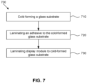
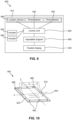
- the display module 126 includes a second glass substrate 130 and a backlight unit 128, as shown in FIG. 4 .
- the second glass substrate 130 is disposed adjacent the first major surface 123 of the glass substrate 124. Accordingly, the second glass substrate 130 is disposed between the backlight unit 128 and the first major surface 123.
- the backlight unit 128 is optionally curved to exhibit the second radius of curvature of the display module 126.
- the backlight unit 128 may be flexible to curve to the second radius of curvature.
- the second glass substrate 130 may be curved to the second radius of curvature.
- the second glass substrate 130 may be cold-bent to exhibit the second radius of curvature. In such embodiments, the second radius of curvature is measured on the surface of the second glass substrate 130 adjacent the glass substrate 124. In one or more embodiments, the second glass substrate 130 may be cold-bent before or during lamination.
- the backlight unit 128 may be attached to the curved glass substrate, the second glass substrate and/or a frame (as described herein) via an adhesive (as described herein) or by mechanical means (e.g., screws, clamps, clips and the like) known in the art.
- the second glass substrate 130 may have a thickness greater than the thickness of the glass substrate 124. In one or more embodiments, the thickness is greater than 1 mm, or about 1.5 mm or greater. In one or more embodiments, the thickness of the second glass substrate 130 may have a thickness that is substantially the same as the glass substrate 124.
- the second glass substrate 130 has a thickness in a range from about 0.1 mm to about 1.5 mm, from about 0.15 mm to about 1.5 mm, from about 0.2 mm to about 1.5 mm, from about 0.25 mm to about 1.5 mm, from about 0.3 mm to about 1.5 mm, from about 0.35 mm to about 1.5 mm, from about 0.4 mm to about 1.5 mm, from about 0.45 mm to about 1.5 mm, from about 0.5 mm to about 1.5 mm, from about 0.55 mm to about 1.5 mm, from about 0.6 mm to about 1.5 mm, from about 0.65 mm to about 1.5 mm, from about 0.7 mm to about 1.5 mm, from about 0.1 mm to about 1.4 mm, from about 0.1 mm to about 1.3 mm, from about 0.1 mm to about 1.2 mm, from about 0.1 mm to about 1.1 mm, from about 0.1 mm to about 1.05 mm, from about 0.1 mm to about 1 mm, from about
- the second glass substrate 130 may have the same glass composition as the glass substrate 124 or may differ from the glass composition used for the glass substrate 124.
- the second glass substrate 130 may have an alkali-free glass composition. Suitable glass compositions for use in the second glass substrate 130 may include soda lime glass, alkali-free aluminosilicate glass, alkali-free borosilicate glass, alkali-free boroaluminosilicate glass, alkali-containing aluminosilicate glass, alkali-containing borosilicate glass, and alkali-containing boroaluminosilicate glass.
- the second glass substrate 130 may be strengthened (as disclosed herein with respect to the glass substrate 124).
- the second glass substrate 130 is unstrengthened or strengthened only by mechanical and/or thermal strengthening (i.e., not strengthened by chemical strengthening).
- the second glass substrate 130 may be annealed.
- the display module 126 may include an organic light-emitting diode (OLED) display.
- OLED organic light-emitting diode
- the first radius of curvature of the glass substrate 124 may be within 10% of the second radius of curvature of the OLED display or the curved surface on which it is assembled (such as a base).
- the frame 134 is associated or assembled with the glass substrate 124, the second glass substrate 130 or another component of the display module in the case of OLED displays.
- the frame can either at least partially surround the minor surface of the glass substrate 124 or the minor surface of the glass substrate may not be surrounded by the frame.
- the frame may include secondary flanges 136 that extend to partially surround the second glass substrate 124, the minor surface of the glass substrate 124, and/or another component of the display module in the case of OLED displays.
- DOI 1 ⁇ Ros Rs ⁇ 100 , where Ros is the relative reflection intensity average between 0.2° and 0.4 away from the specular reflection direction, and Rs is the relative reflection intensity average in the specular direction (between +0.05° and -0.05°, centered around the specular reflection direction).
- the input light source angle is +20° from the sample surface normal (as it is throughout this disclosure), and the surface normal to the sample is taken as 0°, then the measurement of specular reflected light Rs is taken as an average in the range of about -19.95° to -20.05°, and Ros is taken as the average reflected intensity in the range of about -20.2° to -20.4° (or from -19.6° to -19.8°, or an average of both of these two ranges).
- DOI values should be directly interpreted as specifying a target ratio of Ros/Rs as defined herein.
- the anti-glare surface has a reflected scattering profile such that > 95% of the reflected optical power is contained within a cone of +/- 10°, where the cone is centered around the specular reflection direction for any input angle.
- the resulting the anti-glare surface may include a textured surface with plurality of concave features having an opening facing outwardly from the surface.
- the opening may have an average cross-sectional dimension of about 30 micrometers or less.
- the anti-glare surface exhibits low sparkle (in terms of low pixel power deviation reference or PPDr) such as PPDr of about 6% or less.
- PPDr pixel power deviation referenced
- PPDr refer to the quantitative measurement for display sparkle.
- PPDr is measured using a display arrangement that includes an edge-lit liquid crystal display screen (twisted nematic liquid crystal display) having a native sub-pixel pitch of 60 ⁇ m x 180 ⁇ m and a sub-pixel opening window size of about 44 ⁇ m x about 142 ⁇ m.
- the front surface of the liquid crystal display screen had a glossy, anti-reflection type linear polarizer film.
- a screen is placed in the focal region of an "eye-simulator" camera, which approximates the parameters of the eye of a human observer.
- the camera system includes an aperture (or “pupil aperture”) that is inserted into the optical path to adjust the collection angle of light, and thus approximate the aperture of the pupil of the human eye.
- the iris diaphragm subtends an angle of 18 milliradians.
- the easy-to-clean surface includes an oleophobic coating that imparts anti-fingerprint properties.
- the haptic surface includes a raised or recessed surface formed from depositing a polymer or glass material on the surface to provide a user with tactile feedback when touched.
- the surface treatment i.e., the easy-to-clean surface, the anti-glare surface, the anti-reflective surface, the haptic surface and/or the decorative surface
- the surface treatment is disposed on at least a portion of the periphery and the interior portion is substantially free of the surface treatment.
- the display module includes touch functionality and such functionality is accessible through the glass substrate.
- displayed images or content shown by the display module is visible through the glass substrate.
- a further aspect of this disclosure pertains to various methods and systems for cold-bending a glass substrate, such as substrate 124, and/or forming a display.
- the methods and systems discussed herein utilize air pressure differentials to cause bending of the glass substrate.
- these systems and methods bend the glass substrate without use of the high temperatures (e.g., temperatures greater than the glass softening point) that are typical with hot-bending/hot-forming processes.
- the method includes a step 710 of cold-bending a glass substrate, such as substrate 124, to a first radius of curvature (as described herein), and laminating a display module 126 to the first one of the major surfaces (see FIGS. 1 and 2 ) while maintaining the first radius of curvature in the glass substrate to form the display.
- the display module has a second radius of curvature (as described herein) that is within 10% of the first radius of curvature. As shown in FIG.
- cold-bending the glass substrate includes applying a vacuum to the first second major surface of the glass substrate to generate the first radius of curvature 714.
- applying the vacuum includes placing the glass substrate on a vacuum fixture 712 before applying the vacuum to the second major surface.
- the glass substrate and subsequent assembly with the display module is performed while the vacuum is applied to the glass substrate to cold-bend the glass substrate to the first radius of curvature.
- the glass substrate 124 is temporarily cold-bent by applying the vacuum, and subsequent lamination with the display module 126 permanently cold-bends the glass substrate and forms the display.
- the display module provides the rigidity needed to permanently cold-bend the glass substrate.
- Other mechanisms to temporarily cold-bend the glass substrate may be used.
- the glass substrate may be temporarily affixed to a mold having the desired curvature to cold-bend the glass substrate.
- the glass substrate may be temporarily affixed by a pressure sensitive adhesive or other mechanism.
- the method of one or more embodiments includes laminating an adhesive to the first major surface of the glass substrate 124 before laminating the display module to the first major surface such that the adhesive is disposed between the first major surface and the display module.
- laminating the adhesive may include applying a layer of the adhesive and then applying a normal force using roller or other mechanism.
- Exemplary examples include any suitable optically clear adhesive for bonding the glass substrate to the second glass substrate of the display module 126.
- the adhesive may include an optically clear adhesive available from 3M Corporation under the trade name 8215.
- the thickness of the adhesive may be in a range as otherwise described herein (e.g., from about 200 ⁇ m to about 500 ⁇ m).
- step 730 of laminating a display module includes laminating the second glass substrate to the glass substrate (step 732 in FIG. 8 ) and then attaching the backlight unit to the second glass substrate (step 734, in FIG. 8 ).
- the method includes cold-bending the second glass substrate during lamination to the glass substrate.
- the second glass substrate is curved prior to lamination.
- the second glass substrate may be temporarily curved or cold-bent before lamination to exhibit the second radius of curvature.
- the backlight unit is curved to exhibit the second radius of curvature.
- the backlight unit is flexible and is curved during lamination to the second radius of curvature.
- the backlight unit may be curved prior to lamination.
- the backlight unit may be temporarily curved before lamination to exhibit the second radius of curvature.
- the backlight unit may be permanently curved to exhibit the second radius of curvature).
- step 734 includes attaching a frame to one of the backlight unit and the second glass substrate.
- the method includes step 740 of removing the vacuum from the second major surface of the glass substrate 124. For example, removing the vacuum from the second major surface may include removing the display from the vacuum fixture.
- the cold-bending processes discussed herein are believed to generate curved glass substrates with a variety of properties that are superior to hot-formed glass substrates, particularly for display cover glass applications.
- heating during hot-forming processes decreases optical properties of curved glass substrates, and may increase optical distortion.
- the curved glass substrates formed utilizing the cold-bending processes/systems discussed herein provide for both curved glass shape along with improved optical qualities not believed achievable with hot-bending processes.
- glass coating materials e.g., anti-reflective coatings
- deposition processes such as sputtering processes that are typically illsuited for coating curved glass articles.
- coating materials also are not able to survive the high temperatures associated with hot-bending processes.
- one or more coating materials are applied to a major surface and/or to a second major surface of the glass substrate prior to cold-bending (when the glass substrate is flat), and the coated glass substrate is bent to a curved shape as discussed herein.
- the processes and systems discussed herein allow for bending of glass after one or more coating materials have been applied to the glass, in contrast to typical hot-forming processes.
- Embodiments herein relate to dynamically adjustable display systems. Some embodiments relate to dynamically adjustable display systems that automatically adjust a flexible display based upon ambient lighting conditions in order to improve or optimize visibility of the flexible display.
- the display system 100 can be mounted on a support surface or a support structure, such as a wall, table, or countertop, for use as an automated teller machine display, a check-in/check-out display, or a display for placing an order at a store or restaurant, among others.
- the display system 100 can also be incorporated into a free-standing device, such as a podium or the like.
- the display system 100 can also be incorporated into any of various vehicles, such as a plane, a boat, or an automobile, among others.
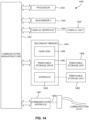
- the display system 900 may include a flexible display 920 capable of bending along one or more bending axes, a plurality of photodetectors 940 for detecting ambient light, a control unit 950 in communication with the photodetectors 940 and an adjustable support 960 that is configured to adjust the flexible display 920.
- the control unit 950 can cause the adjustable support 960 to adjust the flexible display 920, such as by bending the flexible display 920, based on ambient light detected at each of the photodetectors 940 in order to reduce the amount or intensity of ambient light detected by at least one of the photodetectors 940 so as to improve or optimize the visibility of media on the flexible display 920.
- Flexible display 920 may include a substrate (e.g., substrate 124) and a display module (e.g., display module 126) as discussed herein. Further, display 920 may include components associated with glass substrate 124 and/or display module 126 as discussed herein, for example, a backlight unit, a second glass substrate, etc.
- a flexible display 920 of a dynamically adjustable display system 900 is shown by FIG. 10 .
- the flexible display 920 is capable of bending in a reversible manner.
- the term "bending" as used herein, refers to a change in the shape/configuration of the flexible display itself by bending the display about an axis extending on or parallel to a surface of the display (e.g., the first major surface and/or the second major surface 123/125 of substrate 124) without otherwise altering of the position of the display.
- the flexible display 920 may originally have a planar configuration and can bend into a concave configuration, a convex configuration, or a combination thereof.
- the flexible display 920 may originally have a concave configuration, a convex configuration, or a combination thereof and can bend into a flat or planar configuration.
- the flexible display 920 may have an original curvature or be bent to any curvature as discussed herein.
- the flexible display 120 can bend reversibly, the flexible display 120, once bent, can return to its original configuration.
- the flexible display 120 once bent, can bend into a different configuration.
- the flexible display 920 may originally have a flat or planar configuration, and can be bent so as to have a concave configuration, and then can be further bent to have a convex configuration, and subsequently returned to the planar configuration.
- the flexible display 920 includes a cold-bent glass substrate, as discussed in detail herein.
- the cold-bent glass substrate has a number of advantages over conventional glass articles formed by conventional thermal-shaping processes, including among other benefits, the ability to reversibly bend without fatigue, reduced cost of construction, and improved optical and surface properties.
- the flexible display 920 is shown in a first position in which the flexible display 920 is substantially planar.
- the flexible display 920 is further shown as bending to a hypothetical second position about a transverse axis, X, extending on or parallel to a surface of the flexible display 920 in which the flexible display 920 has a generally concave configuration.
- the entire flexible display 920 may bend about a bending axis, or only a portion thereof may bend about the bending axis, such that a first portion of the flexible display is bent, while a second portion remains unbent (e.g. substantially flat or planar).
- the flexible display 920 can bend along a bending axis to a desired degree, and may be bent about the bending axis to a greater or lesser extent as desired.
- the flexible display 920 can bend about alternate bending axes, such as a longitudinal axis, Z.
- the bending axis need not be a transverse or longitudinal axis, and can be a diagonal axis extending on or parallel to a surface of the flexible display 920.
- the flexible display 920 is capable of bending about one or more bending axes. In some embodiments, the flexible display 920 can be bent along multiple bending axes simultaneously. For example, a first portion of a flexible display 920 can be bent in a first bending direction, and a second portion of the flexible display 920 can be bent in a second bending direction.
- the display system 900 further includes an adjustable support 960 that is configured to selectively adjust the flexible display 920.
- the flexible display 920 is mounted on the adjustable support 960 so that the adjustable support 960 can adjust the configuration and position of the flexible display 920.
- the adjustable support 960 can adjust the flexible display 920 by bending the flexible display 920.
- the adjustable support 960 may be connected to a rear surface 964 of the flexible display 920 and a front, user-facing surface of the flexible display 920 is used to display media to be viewed by a user.
- the adjustable support 960 includes one or more mechanical actuators 966 for selectively bending the flexible display 920.
- the mechanical actuators 966 may be connected to various portions of the flexible display 920 such that each mechanical actuator 966 can exert a force on a different portion of the flexible display 920. In this way, one or more actuators 966 can be actuated so as to bend the flexible display 920 in a particular manner, such by bending the flexible display 920 along one or more bending axes. Further, the actuators 966 are capable of bending the flexible display 920 to various extents, such that the degree of bending of the flexible display 920 can be adjusted incrementally.
- the mechanical actuator 966 may be one or more legs having a portion thereof affixed to the flexible display 920 and having a second portion that is movable about a hinge, wherein the leg may be mechanically rotated about the hinge so as to bend the display via a drive mechanism, such as a motor, among others.
- the flexible display 920 may bend along multiple bending axes.
- the mechanical acuator 966 may inlcude a chain which is fixed to a portion (e.g., top porion) of rear surface 964 of flexible display 920 in a sealed track formed in rear surface 964.
- the flexible display 920 will curl in a direction of push force or pull force exerted by the chain.
- the flexible display 920 may bend along multiple bending axes.
- the flexible display 920 may bend by means of one or more piezoelectric actuators.
- the adjustable support 960 is further configured to tilt the flexible display 920.
- tilt refers to a change in the position of the flexible display 920, such as by rotating or pivoting the flexible display 920 about a fixed point without bending the flexible display 920.
- the adjustable support 960 may be tilted by means of the one or more mechanical actuators 966. The ability of the adjustable support 960 to bend the flexible display 920 as well as pivot the flexible display 920 provides additional possible configurations and positions of the flexible display 920 for improving or optimizing visibility of the flexible display 920.
- the adjustable support 960 may also be capable of manual adjustment by a user so that the user can selectively position and bend the flexible display 920 in a desired manner.
- the display system 900 may include one or more actuators 930, such as buttons, controls, or levers, for allowing the user to manually adjust the flexible display 920 using the actuators 930. This provides the user with more control in determining the optimal viewing position for the flexible display 920 and allows the user to override the positioning of the flexible display 920 as determined by the display system 900, if desired.
- the display system 900 further includes a control unit 950 for managing operation of the display system 900.
- the embodiments described herein are not limited to a particular type of control unit 950.
- FIG. 14 illustrates an exemplary computer system 1450 in which embodiments, or portions thereof may be implemented as computer readable code. For example, collecting ambient light information, determining a bending direction and/or bending degree, and actuating the mechanical actuators may be implemented in a computer system 1450 using hardware, software, firmware, tangible computer readable media having instructions stored thereon, or a combination thereof and may be implemented in one or more computer systems or other processing systems.
- a control unit 950 discussed herein may be a computer system having all or some components of the computer system for implementing processes discussed herein.
- FIG. 14 shows an exemplary configuration of a control unit 1450 according to some embodiments.
- the control unit 950 may be in wired or wireless connection with the adjustable support 960.
- the control unit 950 may be programmed to automatically bend the flexible display 920 in a particular manner upon the occurrence of particular events. For example, when the display system is a vehicle display system (as shown in FIG. 13 ), the control unit 950 may bend the flexible display 920 from a storage configuration to an operational configuration upon starting the vehicle ignition and may automatically bend the flexible display 920 from the operational configuration to the storage configuration upon placing the vehicle in park or turning off the ignition.
- the control unit 950 may be in communication with one or more sensors for determining whether such conditions are met, such as a sensor to determine whether the vehicle's ignition is on or off.
- the flexible display 920 is in a storage configuration when not in use, and may automatically bend into an operational configuration when in use, such as when the display system 900 detects the presence of a user nearby, or when a control or actuator is operated by a user.
- control unit 950 may further cause the adjustable support 960 to bend the flexible display 920 based upon an input.
- the control unit 950 may receive an input by means of one or more sensors (e.g., photodetectors or location sensors) in communication with the control unit 950.
- the display system 900 includes a plurality of photodetectors 940, as shown in FIGS. 9-10 .
- the control unit 950 causes the adjustable support 960 to bend the flexible display 920 based upon input received by the photodetectors 940, such as information about the amount, intensity or direction of ambient light detected at each of the plurality of photodetectors 940.
- the photodetector 940 may be a photodiode sensor or an optical sensor, such as a camera.
- the photodetectors 940 may be embedded within the flexible display 920.
- the flexible display 920 may itself serve as one or more photodetectors 940.
- an organic light emitting diode (OLED) display may be configured to sense light if the OLED stack is negatively biased so as to form a photodiode.
- a liquid crystal display (LCD) may be modified so as to include a thin-film-transistor (TFT) capable of sensing light.
- TFT thin-film-transistor
- a plurality of pixels of the display 920 may serve as the photodetectors 940.
- the pixels may detect ambient light in the time between addressing frames of an image or video shown on the display 920.
- the photodetectors 940 may be in wired or wireless communication with the control unit 950.
- the photodetectors 940 are positioned about a perimeter 922 of the flexible display 920. In this way, the photodetectors 940 are positioned so as to determine the amount and direction of ambient light at various portions of the flexible display 920.
- the photodetectors 940 may be positioned about the entire perimeter 922 of the flexible display 920 or only a portion of the perimeter 922. By positioning the photodetectors 940 about the entire perimeter 922 of the flexible display 920, the ambient light at various portions of the flexible display 920 can be used to determine the direction of the ambient light and further which portions of the flexible display 920 are receiving the highest amount or intensity of ambient light.
- the plurality of photodetectors 940 may be regularly positioned along the perimeter 922 of the flexible display 920.
- the photodetectors 940 may be equally spaced from one another.
- the photodetectors 940 may alternatively or additionally be arranged in a pattern.
- one photodetector 940 may be positioned at each corner of a square or rectangular shaped flexible display 920, and/or each edge of the flexible display 920 may have one photodetector 940 that is centrally positioned thereon.
- the photodetectors 940 are fixed to the flexible display 920. In this way, the position of the photodetectors 940 changes as the flexible display 920 bends, such that the photodetectors 940 can detect light based upon the position and configuration of the flexible display 920.
- the photodetectors 940 may be disposed on a border 970 that extends along the perimeter 922 of the flexible display 920. In this way, the photodetectors 940 are secured to the flexible display 920 via the border 970.
- the border 970 may be composed of a flexible or bendable material so that the border 970 is capable of bending as the flexible display 920 bends. As the photodetectors 940 are attached to the flexible display 920 by the border 970, the position of the photodetectors 940 changes as the flexible display 920 bends.
- the display system 900 is configured to dynamically adjust the flexible display 920 in response to ambient lighting conditions.
- each of the plurality of photodetectors 940 detects an intensity and/or direction of ambient light at a different position on the flexible display 920.
- the control unit 950 receives information from the photodetectors 940 relating to the intensity and/or direction of ambient light and signals the adjustable support 960 to bend the flexible display 920 based upon the information from the photodetectors 940.
- the control unit 950 determines which photodetector or photodetectors 940 are receiving the highest intensity of ambient light. Based on this information, the control unit 950 determines a bending direction so as to bend the flexible display 920 away from the photodetector(s) receiving the highest intensity of light. The control unit 950 determines a bending degree that indicates how far to bend the flexible display 920 in the bending direction. The bending degree may be proportional to the intensity of ambient light detected such that the flexible display 920 is bent to a greater degree as the intensity of ambient light detected increases. For example, where the ambient light is of relatively low intensity, only a small degree of bending may be required to render the flexible display 920 viewable by a user. Where the ambient light is of a higher intensity, a greater degree of bending may be required to render the flexible display 920 viewable by a user.
- the control unit 950 bends the flexible display 920 so as to reduce the amount or intensity of ambient light detected by at least one of the plurality of photodetectors 940.
- the control unit 950 may set a threshold intensity of ambient light below which no adjustment of the flexible display 920 is necessary for a user to view the flexible display 920.
- the display system 900 may begin to automatically adjust the flexible display 920 so as to reduce the intensity of ambient light detected by at least one of the plurality of photodetectors 940.
- the flexible display 920 may be adjusted until the intensity of ambient light is at or below the threshold intensity.
- the flexible display 920 may adjust until the intensity of ambient light is reduced by a predetermined amount. This may be preferable in high ambient lighting conditions where it may not be possible to adjust the flexible display 920 so as to reduce the intensity of ambient light below the threshold intensity.
- the flexible display 920 may simply be adjusted in a predetermined fashion based upon the amount or intensity of ambient light originally detected. For example, in response to a photodetector 940 detecting ambient light above a threshold intensity, the display system 900 may automatically bend the flexible display 920 in a bending direction away from the photodetector 940 detecting the high intensity ambient light and bend the flexible display 920 to a predetermined degree.
- control unit 950 is configured to display media on the flexible display 920, such as text, images, video, or a combination thereof.
- the control unit 950 may reposition the media on the flexible display 920 so as to improve or optimize the visibility of the media.
- the control unit 950 may shift the media to a portion of the flexible display 920 away from a portion of the display 920 receiving a high amount or intensity of ambient light detected by one or more of the photodetectors 940.
- the display system 900 further includes one or more location sensors 980.
- the location sensors 980 may be optical sensors.
- the location sensors 980 are configured to detect a location of a user.
- the location sensors 980 may detect the location of the user's body, or a location of a particular body part or portion of the user, such as the user's head or eyes.
- the one or more location sensors 980 may be operably connected to the control unit 950 such that the control unit 950 causes the adjustable support 960 to adjust the flexible display 920 based on the location of the user as determined by the location sensors 980.
- the control unit 950 may adjust the flexible display 920 based upon information from the photodetectors 940 as well as from the location sensors 980. Thus, the control unit 950 may determine a location of the user based on the location sensors 980. The control unit 950 may adjust the flexible display 920 so as to orient the flexible display 920 towards the location of the user determined by the location sensors 980. In embodiments in which the flexible display 920 is able to tilt, the control unit 950 may tilt the flexible display 920 towards the location of the user.
- the control unit 950 may further determine a bending degree, i.e., the extent to which the flexible display 920 will be bent in the bending direction.
- the control unit 950 can cause the adjustable support 960 to bend and/or tilt the flexible display 920 so as to reduce the ambient light detected by at least one of the photodetectors 940.
- the control unit 950 may optimize the visibility of the flexible display 920 from the perspective of the user's location as determined by the location sensors 980.
- the control unit 950 may serve to tilt and/or bend the flexible display 920 to reduce the intensity of ambient light with the display 920 oriented towards the user's location.
- a single glass substrate 1224 is positioned such that a major surface of the glass substrate 1224 is in contact with a surface of each display module 1226.
- Each display module 1226 may be independently positionable, and may be capable of pivoting or tilting relative to the other display module(s) 1226.
- one or both display modules 1226 can be tilted, such that the display modules 1226 form an L-shape or V-shape, in order to adjust the viewing position of the display module(s) 1226.
- the glass substrate 1224 covering the display modules 1226 bends in a corresponding manner while the display modules 1226 retain their configuration (i.e., without bending of the display modules).
- the support structure 1250 may be any of various structures to which it may be desirable to mount a flexible display, including a portion of a vehicle, such as a center console, steering wheel, or dashboard, a building structure, such as a wall, floor, ceiling or countertop, or a free-standing structure, such as a podium, a table, a housing, or the like.
- the second portion 1224b of the glass substrate can be affixed to the support structure 1250 by any of various means, such as by the use of mechanical fasteners, adhesives or epoxies, or brackets, among others fastening methods.
- a central portion 1227 of the glass substrate can bend so as to allow the flexible display 1220 to be variously positioned relative to the support structure 1250.
- the display system is used as a vehicle display system 1300, as shown for example in FIG. 13 .
- the vehicle display system 1300 can be incorporated into vehicles such as trains, automobiles (e.g., cars, trucks, buses and the like), seacraft (e.g., boats, ships, submarines, and the like), and aircraft (e.g., drones, airplanes, jets, helicopters and the like), including both human-piloted vehicles, semiautonomous vehicles and fully autonomous vehicles.
- the vehicle display system 1300 includes a vehicle base 1305, such as a center console, a dashboard, or a steering wheel of a vehicle.
- the vehicle base 1305 may include various other vehicle portions, such as an arm rest, a pillar, a seat back, a floor board, a headrest, a door panel, or any portion of the interior of a vehicle.
- the vehicle display system 1300 may be integrated with the electronics and/or power system of the vehicle, or the vehicle display system 1300 may be separate therefrom.
- the flexible display 1320 may be manufactured as part of the vehicle or may be retrofitted.
- a flexible display 1320, of the type described herein, is mounted on an adjustable support which is mounted on the vehicle base 1305.
- a rear surface of the flexible display 1320 may be in contact with the adjustable support such that a front, user-facing surface of the flexible display 1320 faces the vehicle interior so that an image on the flexible display 1320 can be viewed by vehicle occupants.
- the flexible display 1320 may be positioned so as to form a portion of the vehicle base 1305 and may follow the shape and contour thereof.
- the flexible display 1320 may be extended from the vehicle base 1305 when the vehicle is in use, such that the flexible display 1320 moves into an operating position in which it is more easily viewed by a user, such as a driver, and no longer follows the shape and contour of the vehicle base 1305.
- the vehicle display system 1300 is incorporated into a vehicle base 1305 that is a center console.
- the flexible display 1320 can have any of the constructions as described herein, and may include a glass substrate, such as a cold-bent glass substrate, and a display module, which may include a backlight unit and a second glass substrate.
- Photodetectors 1340 are located about the perimeter of the flexible display 1320, for example, on or in a border 1330 of the flexible display 1320.
- one or more location sensors 1380 may be integrated into the display system 1300.
- the location sensors 1380 may also be positioned about a perimeter of the flexible display 1320, for example on or in the border 1330 on or in which the photodetectors 1340 are positioned.
- the photodetectors 1340 and the location sensors 1380 are operably connected to a control unit (e.g., control unit 950).
- the location sensors 1380 may determine whether a user is in the vehicle, and further a location of users within the vehicle.
- the location sensor 1380 may detect the presence and location of the driver and optimize viewing of the flexible display 1320 from the location of the driver.
- the flexible display 1320 may tilt and/or bend so as to reduce the intensity of ambient light detected at one or more of the photodetectors 1340, and may tilt or bend to avoid directing light towards the user, so as to reduce or eliminate glare.
- the display system 1300 helps to improve or optimize the visibility of the display 1320 in response to ambient lighting conditions and without intervention by the user.
- FIG. 14 illustrates an exemplary computer system 1450 in which embodiments, or portions thereof, may be implemented as computer-readable code.
- collection of ambient light data i.e., data from photodetectors
- location sensor data i.e., location sensor data
- determining a bending and/or tilting direction may be implemented in computer system 1450 using hardware, software, firmware, tangible computer readable media having instructions stored thereon, or a combination thereof and may be implemented in one or more computer systems or other processing systems.
- Control units discussed herein may be computer systems having all or some of the components of computer system 1450 for implementing processes discussed herein.
- programmable logic may execute on a commercially available processing platform or a special purpose device.
- control unit configurations including multi-core processor systems, minicomputers, and mainframe computers, computer linked or clustered with distributed functions, as well as pervasive or miniature computers that may be embedded into virtually any device.
- processor devices may be used to implement the above described embodiment.
- a processor device may be a single processor, a plurality of processors, or combinations thereof.
- Processor devices may have one or more processor "cores.”
- Processor device 1451 may be a special purpose or a general purpose processor device. As will be appreciated by persons skilled in the relevant art, processor device 1451 may also be a single processor in a multi-core/multiprocessor system, such system operating alone, or in a cluster of computing devices operating in a cluster or server farm. Processor device 1451 is connected to a communication infrastructure 1457, for example, a bus, message queue, network, or multi-core message-passing scheme.
- Computer system 1450 also includes a main memory 1452, for example, random access memory (RAM), and may also include a secondary memory 1454.
- Secondary memory 1454 may include, for example, a hard disk drive 1455, or removable storage drive 1456.
- Removable storage drive 1456 may include a floppy disk drive, a magnetic tape drive, an optical disk drive, a flash memory, or the like.
- the removable storage drive 1456 reads from and/or writes to a removable storage unit 1459 in a well-known manner.
- Removable storage unit 1459 may include a floppy disk, magnetic tape, optical disk, a universal serial bus (USB) drive, etc. which is read by and written to by removable storage drive 1456.
- removable storage unit 1459 includes a computer usable storage medium having stored therein computer software and/or data.
- Computer system 1450 (optionally) includes a display interface 1453 (which can include input and output devices such as a keyboard) that forwards graphics, text, and other data from communication infrastructure 1457 (or from a frame buffer, not shown) for display on display 1420.
- display interface 1453 which can include input and output devices such as a keyboard
- secondary memory 1454 may include other similar means for allowing computer programs or other instructions to be loaded into computer system 1450.
- Such means may include, for example, a removable storage unit 1460 and an interface 1458.
- Examples of such means may include a program cartridge and cartridge interface (such as that found in video game devices), a removable memory chip (such as an EPROM, or PROM) and associated socket, and other removable storage units 1460 and interfaces 1458 which allow software and data to be transferred from the removable storage unit 1460 to computer system 1450.
- Computer system 1450 may also include a communication interface 1461.
- Communication interface 1461 allows software and data to be transferred between computer system 1450 and external devices.
- Communication interface 1461 may include a modem, a network interface (such as an Ethernet card), a communication port, a PCMCIA slot and card, or the like.
- Software and data transferred via communication interface 1461 may be in the form of signals, which may be electronic, electromagnetic, optical, or other signals capable of being received by communication interface 1461. These signals may be provided to communication interface 1461 via a communication path 1462.
- Communication path 1462 carries signals and may be implemented using wire or cable, fiber optics, a phone line, a cellular phone link, an RF link or other communication channels.
- computer program medium and “computer usable medium” are used to generally refer to media such as removable storage unit 1459, removable storage unit 1460, and a hard disk installed in hard disk drive 1455.
- Computer program medium and computer usable medium may also refer to memories, such as main memory 1452 and secondary memory 1454, which may be memory semiconductors (e.g. DRAMs, etc.).
- Computer programs are stored in main memory 1452 and/or secondary memory 1454. Computer programs may also be received via communication interface 1461. Such computer programs, when executed, enable computer system 1450 to implement the embodiments as discussed herein. In particular, the computer programs, when executed, enable processor device 1451 to implement the processes of the embodiments discussed herein. Where the embodiments are implemented using software, the software may be stored in a computer program product and loaded into computer system 1450 using removable storage drive 1456, interface 1458, and hard disk drive 1455, or communication interface 1461.
- Embodiments of the invention(s) also may be directed to computer program products comprising software stored on any computer usable medium. Such software, when executed in one or more data processing devices, causes a data processing device to operate as described herein. Embodiments may employ any computer useable or readable medium. Examples of computer useable medium include, but are not limited to, primary storage devices (e.g., any type of RAM), secondary storage devices (e.g., hard drives, floppy disks, CD ROMS, ZIP disks, tapes, magnetic storage devices, optical storage devices, MEMS, nanotechnological storage devices, etc.).
- primary storage devices e.g., any type of RAM
- secondary storage devices e.g., hard drives, floppy disks, CD ROMS, ZIP disks, tapes
- magnetic storage devices e.g., magnetic tapes, magnetic storage devices, optical storage devices, MEMS, nanotechnological storage devices, etc.
- indefinite articles “a” and “an” to describe an element or component means that one or at least one of these elements or components is present. Although these articles are conventionally employed to signify that the modified noun is a singular noun, as used herein the articles “a” and “an” also include the plural, unless otherwise stated in specific instances. Similarly, the definite article “the,” as used herein, also signifies that the modified noun may be singular or plural, again unless otherwise stated in specific instances.
- the term "about” means that amounts, sizes, ranges, formulations, parameters, and other quantities and characteristics are not and need not be exact, but may be approximate and/or larger or smaller, as desired, reflecting tolerances, conversion factors, rounding off, measurement error and the like, and other factors known to those of skill in the art.
- substantially is intended to note that a described feature is equal or approximately equal to a value or description.
- a “substantially planar” surface is intended to denote a surface that is planar or approximately planar.
- substantially is intended to denote that two values are equal or approximately equal.
- substantially may denote values within about 10% of each other, such as within about 5% of each other, or within about 2% of each other.
Landscapes
- Engineering & Computer Science (AREA)
- Physics & Mathematics (AREA)
- Computer Hardware Design (AREA)
- General Physics & Mathematics (AREA)
- Theoretical Computer Science (AREA)
- Chemical & Material Sciences (AREA)
- Combustion & Propulsion (AREA)
- Transportation (AREA)
- Mechanical Engineering (AREA)
- Devices For Indicating Variable Information By Combining Individual Elements (AREA)
- Surface Treatment Of Glass (AREA)
Claims (13)
- Dynamisch einstellbares Anzeigesystem, aufweisend:eine flexible Anzeige (920), die in der Lage ist, sich entlang einer Vielzahl von Biegeachsen reversibel zu biegen;eine einstellbare Halterung (960), an der die flexible Anzeige (920) angebracht ist, wobei die einstellbare Halterung (960) dafür ausgelegt ist, die flexible Anzeige (920) zielgerichtet zu biegen, wobei die einstellbare Halterung (960) eine oder mehrere mechanische Stelleinheiten (966) aufweist, die mit der flexiblen Anzeige (920) verbunden sind, wobei die eine oder die mehreren mechanischen Stelleinheiten (966) dafür ausgelegt sind, eine Kraft auf die flexible Anzeige (920) auszuüben, um die flexible Anzeige entlang einer oder mehrerer Biegeachsen zielgerichtet zu biegen;eine Vielzahl von Photodetektoren (940), die um einen Außenumfang der flexiblen Anzeige (920) herum positioniert sind, um Umgebungslicht zu erfassen; undeine Steuereinheit (950) in Kommunikation mit der einstellbaren Halterung (960) und der Vielzahl von Photodetektoren (940), wobei die Steuereinheit (950) dafür ausgelegt ist, als Reaktion auf das an der Vielzahl von Photodetektoren (940) erfasste Umgebungslicht zu verursachen, dass die einstellbare Halterung (960) die flexible Anzeige (920) über die eine oder die mehreren mechanischen Stelleinheiten (966) biegt, und wobei die Steuereinheit (950) dafür ausgelegt ist, eine Biegerichtung und einen Biegegrad für einen Abschnitt der flexiblen Anzeige (920) beruhend auf dem an der Vielzahl von Photodetektoren (940) erfassten Umgebungslicht zu bestimmen,wobei die Photodetektoren dafür ausgelegt sind, eine Intensität und eine Richtung des Umgebungslichts zu erfassen, undwobeidie Steuereinheit (950) dafür ausgelegt ist, zu verursachen, dass die einstellbare Halterung (960) den Abschnitt der flexiblen Anzeige (920) in der Biegerichtung und gemäß dem Biegegrad biegt, um die Intensität des von mindestens einem aus der Vielzahl von Photodetektoren (940) erfassten Umgebungslichts zu reduzieren, wobei die Biegerichtung derart ist, dass der Abschnitt der flexiblen Anzeige (920) von einer Richtung des Umgebungslichts, das über die Vielzahl von Photodetektoren (940) erfasst wird, weg gebogen wird.
- Anzeigesystem nach Anspruch 1, wobei die flexible Anzeige (920) ein kaltgebogenes Glassubstrat (124) aufweist.
- Anzeigesystem nach Anspruch 2, wobei die flexible Anzeige (920) darüber hinaus ein Anzeigemodul (126) aufweist, das an einer Oberfläche des kaltgebogenen Glassubstrats (124) befestigt ist.
- Anzeigesystem nach Anspruch 3, wobei das Anzeigemodul (126) eine organische Leuchtdiodenanzeige aufweist.
- Anzeigesystem nach einem der Ansprüche 1 bis 4, wobei die flexible Anzeige (920) in der Lage ist, sich in eine konkave Konfiguration oder eine konvexe Konfiguration zu biegen.
- Anzeigesystem nach einem der Ansprüche 1 bis 5, wobei die Steuereinheit (950) dafür ausgelegt ist, zu verursachen, dass die einstellbare Halterung (960) die flexible Anzeige (920) so biegt, dass eine Intensität des Umgebungslichts, das von mindestens einem aus der Vielzahl von Photodetektoren (940) erfasst wird, unterhalb eines Schwellenwerts liegt, unter dem keine Biegung der flexiblen Anzeige ausgelöst wird.
- Anzeigesystem nach einem der Ansprüche 1 bis 6, darüber hinaus einen oder mehrere Ortungssensoren (980) aufweisend, die dafür ausgelegt sind, eine Position eines Benutzers zu erfassen, wobei die Steuereinheit (950) darüber hinaus verursacht, dass die einstellbare Halterung (960) die flexible Anzeige (920) beruhend auf der Position des Benutzers einstellt.
- Anzeigesystem nach Anspruch 7, wobei die Steuereinheit (950) dafür ausgelegt ist, die flexible Anzeige (920) so einzustellen, dass die flexible Anzeige zu der durch den einen oder die mehreren Ortungssensoren bestimmten Position des Benutzers hin ausgerichtet ist.
- Verfahren zur dynamischen Einstellung der flexiblen Anzeige des dynamisch einstellbaren Anzeigesystems nach einem der Ansprüche 1 bis 8, wobei das Verfahren umfasst:
durch die Vielzahl von Photodetektoren (940), Erfassen einer Intensität und einer Richtung von Umgebungslicht; und:
durch die Steuereinheit:
Verursachen, dass die einstellbare Halterung (960) die flexible Anzeige (920) über die eine oder die mehreren mechanischen Stelleinheiten (966) als Reaktion auf das an der Vielzahl von Photodetektoren (940) erfasste Umgebungslicht biegt, umfassend:Bestimmen einer Biegerichtung und eines Biegegrads für einen Abschnitt der flexiblen Anzeige (920) beruhend auf dem an der Vielzahl von Photodetektoren (940) erfassten Umgebungslicht, undVerursachen, dass die einstellbare Halterung (960) den Abschnitt der flexiblen Anzeige (920) in der Biegerichtung und gemäß dem Biegegrad biegt, um die Intensität des von mindestens einem aus der Vielzahl von Photodetektoren (940) erfassten Umgebungslichts zu reduzieren,wobei die Biegerichtung derart ist, dass der Abschnitt der flexiblen Anzeige (920) von der Richtung des Umgebungslichts, das über die Vielzahl von Photodetektoren (940) erfasst wird, weg gebogen wird. - Verfahren nach Anspruch 9, darüber hinaus umfassend, eine Biegerichtung zu bestimmen, in der die flexible Anzeige (920) zu biegen ist, und zwar beruhend auf der Intensität des Umgebungslichts, das an jedem aus der Vielzahl von Photodetektoren (940) erfasst wird; und/oder einen Biegegrad zu bestimmen, bis auf den die flexible Anzeige (920) zu biegen ist, und zwar beruhend auf der Intensität des Umgebungslichts, das an der Vielzahl von Photodetektoren (940) erfasst wird.
- Verfahren nach einem der Ansprüche 9 bis 10, darüber hinaus umfassend, die flexible Anzeige (920) beruhend auf einer durch einen oder mehrere Ortungssensoren (980) bestimmten Position eines Benutzers zu biegen.
- Fahrzeuganzeigesystem zur dynamischen Einstellung einer flexiblen Anzeige beruhend auf Umgebungslichtbedingungen, wobei das Fahrzeuganzeigesystem aufweist:eine Fahrzeugbasis (1305); undein dynamisch einstellbares Anzeigesystem (900) nach einem der Ansprüche 1 bis 8, das an der Fahrzeugbasis (1305) angeordnet ist.
- Fahrzeuganzeigesystem nach Anspruch 12, wobei die Fahrzeugbasis (1305) eine Mittelkonsole, ein Armaturenbrett oder ein Lenkrad aufweist.
Applications Claiming Priority (2)
| Application Number | Priority Date | Filing Date | Title |
|---|---|---|---|
| US201862772871P | 2018-11-29 | 2018-11-29 | |
| PCT/US2019/062127 WO2020112433A1 (en) | 2018-11-29 | 2019-11-19 | Dynamically adjustable display system and methods of dynamically adjusting a display |
Publications (2)
| Publication Number | Publication Date |
|---|---|
| EP3888077A1 EP3888077A1 (de) | 2021-10-06 |
| EP3888077B1 true EP3888077B1 (de) | 2025-06-25 |
Family
ID=68848459
Family Applications (1)
| Application Number | Title | Priority Date | Filing Date |
|---|---|---|---|
| EP19818406.1A Active EP3888077B1 (de) | 2018-11-29 | 2019-11-19 | Dynamisch einstellbares anzeigesystem und verfahren zur dynamischen einstellung einer anzeige |
Country Status (5)
| Country | Link |
|---|---|
| US (1) | US11423816B2 (de) |
| EP (1) | EP3888077B1 (de) |
| CN (2) | CN113196373B (de) |
| TW (1) | TWI831874B (de) |
| WO (1) | WO2020112433A1 (de) |
Families Citing this family (6)
| Publication number | Priority date | Publication date | Assignee | Title |
|---|---|---|---|---|
| EP3888077B1 (de) * | 2018-11-29 | 2025-06-25 | Corning Incorporated | Dynamisch einstellbares anzeigesystem und verfahren zur dynamischen einstellung einer anzeige |
| JP7310779B2 (ja) * | 2020-10-26 | 2023-07-19 | トヨタ自動車株式会社 | 表示システム |
| EP4174832A1 (de) * | 2021-10-26 | 2023-05-03 | Bayerische Motoren Werke Aktiengesellschaft | Verarbeitungseinheit, fahrzeug-infotainmentsystem, verfahren und computerprogramm |
| US12229745B2 (en) * | 2023-03-16 | 2025-02-18 | Capital One Services, Llc | Systems and methods for location-based applications for vehicles |
| CN116215399A (zh) * | 2023-03-22 | 2023-06-06 | 上海天马微电子有限公司 | 显示装置及其控制方法 |
| CN119370026A (zh) * | 2023-07-25 | 2025-01-28 | 新加坡商群丰骏科技股份有限公司 | 车用装置 |
Citations (1)
| Publication number | Priority date | Publication date | Assignee | Title |
|---|---|---|---|---|
| US20140204509A1 (en) * | 2013-01-24 | 2014-07-24 | Samsung Display Co, Ltd. | Flexible display device |
Family Cites Families (98)
| Publication number | Priority date | Publication date | Assignee | Title |
|---|---|---|---|---|
| DE2758581C2 (de) | 1977-12-29 | 1980-01-03 | Bfg Glassgroup, Paris | Windschutzscheibe, insbesondere für Kraftfahrzeuge, mit Innenscheibe aus chemisch vorgespanntem Silikatglas |
| DE3012007A1 (de) | 1980-03-28 | 1981-10-08 | Gebr. Happich Gmbh, 5600 Wuppertal | Schaumstoffkoerper, insbesondere armaturentafel fuer kraftfahrzeuge |
| BE1000350A5 (fr) | 1987-02-27 | 1988-11-08 | Saint Roch Glaceries | Panneau vitre cintre. |
| LU87241A1 (fr) | 1988-06-15 | 1990-02-28 | Glaverbel | Procede d'augmentation de la resistance a la penetration au travers d'une baie vitree et vitrage a resistance a l'effraction renforcee |
| DE4415878C2 (de) | 1994-05-05 | 1996-08-14 | Bayerische Motoren Werke Ag | Verbundglasscheibe, insbesondere für Fahrzeuge |
| JP3364081B2 (ja) | 1995-02-16 | 2003-01-08 | 株式会社半導体エネルギー研究所 | 半導体装置の作製方法 |
| DE59700555D1 (de) | 1996-03-02 | 1999-11-18 | Volkswagen Ag | Multifunktionseinrichtung für ein kraftfahrzeug |
| NL1003537C2 (nl) | 1996-07-08 | 1998-01-12 | Holland Railconsult B V | Werkwijze voor het vervaardigen van een gebogen beglazing. |
| JPH1160293A (ja) | 1997-08-06 | 1999-03-02 | Nippon Sheet Glass Co Ltd | 合わせガラスおよび自動車窓構造 |
| JPH11126029A (ja) | 1997-10-22 | 1999-05-11 | Yazaki Corp | 表示器 |
| JP3059337U (ja) | 1998-11-25 | 1999-07-09 | 太陽科学株式会社 | 簡易ポケットチーフ |
| US6582799B1 (en) | 1999-06-02 | 2003-06-24 | Ppg Industries Ohio, Inc. | Laminated transparency |
| DE19929587A1 (de) | 1999-06-29 | 2001-01-04 | Volkswagen Ag | Anzeigeeinrichtung, insbesondere für ein Kraftfahrzeug |
| DE19948491A1 (de) * | 1999-10-07 | 2001-04-12 | Mannesmann Vdo Ag | Kombiinstrument |
| US6953735B2 (en) | 2001-12-28 | 2005-10-11 | Semiconductor Energy Laboratory Co., Ltd. | Method for fabricating a semiconductor device by transferring a layer to a support with curvature |
| DE102004022008A1 (de) | 2003-05-01 | 2004-12-16 | Europtec Gmbh | Glas für Anzeigen und Displays |
| US20070223121A1 (en) | 2006-03-23 | 2007-09-27 | Centre Luxembourgeois De Recherches Pour Le Verre Et La Ceramique S.A. (C.R.V.C.) | Method of making reflector for solar collector or the like and corresponding product |
| US7871664B2 (en) | 2006-03-23 | 2011-01-18 | Guardian Industries Corp. | Parabolic trough or dish reflector for use in concentrating solar power apparatus and method of making same |
| CN101496082A (zh) | 2006-07-27 | 2009-07-29 | 夏普株式会社 | 显示装置 |
| US20090179840A1 (en) | 2006-07-27 | 2009-07-16 | Sharp Kabushiki Kaisha | Display device |
| US8375657B2 (en) | 2007-02-06 | 2013-02-19 | Saint-Gobain Glass France | Insulating glazing unit comprising a curved pane |
| US7619194B2 (en) * | 2007-02-26 | 2009-11-17 | Epson Imaging Devices Corporation | Electro-optical device, semiconductor device, display device, and electronic apparatus having the display device |
| FR2918411B1 (fr) | 2007-07-06 | 2013-10-18 | Faurecia Sys Echappement | Nappe de maintien thermoexpansible. |
| CN102566841B (zh) | 2008-10-31 | 2015-04-15 | 宸美(厦门)光电有限公司 | 曲面状电容式触控板的结构 |
| JP5637140B2 (ja) | 2009-10-20 | 2014-12-10 | 旭硝子株式会社 | ガラス積層体、支持体付き表示装置用パネル、表示装置用パネル、表示装置、およびこれらの製造方法 |
| US8300036B2 (en) | 2010-06-29 | 2012-10-30 | Bank Of America Corporation | Method and apparatus for reducing glare and/or increasing privacy of a self-service device |
| TWI531811B (zh) | 2010-10-28 | 2016-05-01 | 康寧公司 | 影像螢幕保護玻璃照明 |
| TWI467427B (zh) | 2011-10-07 | 2015-01-01 | Young Optics Inc | 觸控顯示裝置 |
| CN103930382B (zh) | 2011-10-10 | 2017-12-12 | 康宁股份有限公司 | 用于急弯玻璃板的设备和方法 |
| US8833106B2 (en) | 2012-09-18 | 2014-09-16 | Corning Incorporated | Thermo-mechanical reforming method and system and mechanical reforming tool |
| SG191883A1 (en) | 2011-10-18 | 2013-08-30 | Fischer Technology Pte Ltd | A method of moulding |
| US8549885B2 (en) | 2011-11-23 | 2013-10-08 | Corning Incorporated | Process and system for precision glass sheet bending |
| TWI497405B (zh) * | 2012-04-11 | 2015-08-21 | Inst Information Industry | 操作複數軟性顯示器互動的方法及互動系統 |
| EP2679551A1 (de) | 2012-06-28 | 2014-01-01 | Corning Incorporated | Verfahren und System zur Feinabstimmung des Glastafel-Präzisionsbiegens |
| KR20140044227A (ko) * | 2012-10-04 | 2014-04-14 | 삼성전자주식회사 | 플렉서블 디스플레이 장치 및 그의 제어 방법 |
| WO2014055583A1 (en) | 2012-10-05 | 2014-04-10 | Corning Incorporated | Glass/metal laminated structures and methods of manufacturing laminated structures |
| EP2941347B1 (de) | 2013-01-07 | 2021-06-02 | Corning Incorporated | Verstärkte verbundglasstrukturen |
| JP5976561B2 (ja) | 2013-02-04 | 2016-08-23 | 株式会社東海理化電機製作所 | 操作装置 |
| US9516743B2 (en) | 2013-02-27 | 2016-12-06 | Apple Inc. | Electronic device with reduced-stress flexible display |
| JP5997655B2 (ja) | 2013-04-26 | 2016-09-28 | 矢崎総業株式会社 | 車両用表示装置 |
| DE102013214108B4 (de) | 2013-07-18 | 2023-05-17 | Bayerische Motoren Werke Aktiengesellschaft | Räumlich gekrümmter Glasformkörper und Verfahren zu dessen Herstellung |
| CN110126393A (zh) * | 2013-08-29 | 2019-08-16 | 康宁股份有限公司 | 薄玻璃层压结构 |
| CN103474580A (zh) | 2013-09-09 | 2013-12-25 | 京东方科技集团股份有限公司 | 柔性有机电致发光器件的封装结构、方法、柔性显示装置 |
| WO2015084902A1 (en) | 2013-12-06 | 2015-06-11 | Corning Incorporated | Methods for forming patterns in thin glass laminate structures |
| KR102347532B1 (ko) | 2014-01-23 | 2022-01-05 | 삼성디스플레이 주식회사 | 접을 수 있는 플렉서블 표시 장치 및 이의 제조 방법 |
| FR3017073B1 (fr) | 2014-02-03 | 2016-03-04 | Holdham | Fiche d'informations, destinee a etre introduite entre deux pages d'un produit de papeterie, tel qu'un cahier |
| KR102216674B1 (ko) | 2014-02-10 | 2021-02-18 | 삼성디스플레이 주식회사 | 폴딩 가능한 디스플레이 장치 |
| CN203825589U (zh) | 2014-04-10 | 2014-09-10 | 上海博泰悦臻电子设备制造有限公司 | 一种曲面触摸显示屏 |
| JP6213737B2 (ja) | 2014-07-30 | 2017-10-18 | 豊田合成株式会社 | タッチパネル装置およびタッチパネル装置の製造方法 |
| CN104197240A (zh) * | 2014-08-19 | 2014-12-10 | 深圳市华星光电技术有限公司 | 曲率可调的复合背板及背光模块 |
| WO2016044360A1 (en) | 2014-09-17 | 2016-03-24 | Corning Incorporated | Curved liquid crystal display panel and process of manufacture |
| TWI660929B (zh) | 2014-10-08 | 2019-06-01 | 美商康寧公司 | 含有金屬氧化物濃度梯度之玻璃以及玻璃陶瓷 |
| CN104407461B (zh) * | 2014-11-26 | 2017-12-12 | 深圳市华星光电技术有限公司 | 曲面液晶显示装置 |
| KR102343141B1 (ko) * | 2014-12-19 | 2021-12-27 | 삼성디스플레이 주식회사 | 스트레쳐블 디스플레이를 이용한 디바이스 및 이의 제어 방법 |
| KR101640053B1 (ko) | 2015-01-02 | 2016-07-18 | 현대자동차주식회사 | 차량용 디스플레이 장치 및 이를 포함하는 차량 |
| CN104503629A (zh) | 2015-01-19 | 2015-04-08 | 欧浦登(顺昌)光学有限公司 | 一种全贴合曲面触控显示屏及其制造工艺 |
| CN204463066U (zh) | 2015-01-19 | 2015-07-08 | 欧浦登(顺昌)光学有限公司 | 一种全贴合曲面触控显示屏 |
| WO2016125713A1 (ja) | 2015-02-05 | 2016-08-11 | 旭硝子株式会社 | 曲面カバーガラス及びその製造方法、並びに車載用表示部材 |
| JP2015092422A (ja) | 2015-02-20 | 2015-05-14 | 株式会社ミクロ技術研究所 | 湾曲型タッチパネル |
| WO2016136758A1 (ja) | 2015-02-25 | 2016-09-01 | 旭硝子株式会社 | 曲面カバーガラス及びその製造方法、並びに、ガラス部材、表示装置、曲面ガラス |
| JP2016173794A (ja) | 2015-03-18 | 2016-09-29 | 小島プレス工業株式会社 | 車両搭載用タッチセンサおよびその製造方法 |
| CN104843976B (zh) | 2015-04-01 | 2018-02-27 | 桂林电子科技大学 | 一种3d曲面超薄玻璃弯曲成型装置和制造方法 |
| JP2016207200A (ja) | 2015-04-20 | 2016-12-08 | ホシデン株式会社 | タッチパネル及びその製造方法 |
| KR20160124665A (ko) | 2015-04-20 | 2016-10-28 | 호시덴 가부시기가이샤 | 터치 패널 및 그 제조방법 |
| KR102300081B1 (ko) | 2015-04-27 | 2021-09-08 | 삼성디스플레이 주식회사 | 합착 장치 및 이를 이용한 곡면 표시 장치의 제조 방법 |
| WO2016183059A1 (en) | 2015-05-11 | 2016-11-17 | Corning Incorporated | Surface display units with opaque screen |
| WO2016196540A1 (en) | 2015-06-02 | 2016-12-08 | Corning Incorporated | Aesthetic surface and display device with such a surface |
| EP3303241A1 (de) | 2015-06-02 | 2018-04-11 | Corning Incorporated | Multifunktionsmaterialsystem für eine oberflächenanzeigeeinheit |
| US20180154615A1 (en) | 2015-06-02 | 2018-06-07 | Corning Incorporated | Glass laminate with pane having glass-glass laminate structure |
| EP3302967A1 (de) | 2015-06-02 | 2018-04-11 | Corning Incorporated | Auf licht reagierende dünnglaslaminate |
| TW201710113A (zh) | 2015-06-02 | 2017-03-16 | 康寧公司 | 車輛投影系統 |
| US9895975B2 (en) | 2015-06-05 | 2018-02-20 | Lg Display Co., Ltd. | Bar type display apparatus and vehicle comprising the same |
| KR102411046B1 (ko) | 2015-06-05 | 2022-06-20 | 엘지디스플레이 주식회사 | 바형 디스플레이 장치 및 이를 포함하는 차량 |
| CN104848798B (zh) * | 2015-06-08 | 2018-09-11 | 京东方科技集团股份有限公司 | 一种柔性显示器及柔性显示屏的弯曲状态检测方法 |
| FR3037890B1 (fr) | 2015-06-29 | 2019-03-15 | Faurecia Sieges D'automobile | Realisation d'un element d'habillage pour siege de vehicule automobile ou habitacle de vehicule automobile |
| WO2017011270A1 (en) | 2015-07-10 | 2017-01-19 | Corning Incorporated | Cold formed laminates |
| US9947882B2 (en) | 2015-09-25 | 2018-04-17 | Apple Inc. | Electronic devices with robust flexible displays |
| TWI557708B (zh) * | 2015-11-05 | 2016-11-11 | 宏碁股份有限公司 | 顯示裝置和顯示方法 |
| CN106873814B (zh) | 2015-12-14 | 2020-02-21 | 联想(北京)有限公司 | 一种控制方法及电子设备 |
| CN106886321A (zh) | 2015-12-15 | 2017-06-23 | 群创光电股份有限公司 | 触控结构与制作方法及其应用装置 |
| CN105511127B (zh) | 2016-01-26 | 2020-11-06 | 深圳市华星光电技术有限公司 | 曲面显示屏贴合设备 |
| EP3426614B1 (de) | 2016-03-09 | 2024-11-20 | Corning Incorporated | Kaltformung von komplex gekrümmten glasartikeln |
| US9858848B1 (en) | 2016-06-09 | 2018-01-02 | International Business Machines Corporation | Dynamic display adjustment on a transparent flexible display |
| JP7051720B2 (ja) | 2016-06-28 | 2022-04-11 | コーニング インコーポレイテッド | 装飾用途とディスプレイ用カバー用途のための湾曲成形プラスチック表面への薄い強化ガラスの積層 |
| TWI730140B (zh) | 2016-07-05 | 2021-06-11 | 美商康寧公司 | 冷成形玻璃製品及其組裝製程 |
| US10311723B2 (en) | 2016-07-15 | 2019-06-04 | Intel Corporation | Parking management system and method |
| DE102016215546A1 (de) | 2016-08-18 | 2018-02-22 | Faurecia Innenraum Systeme Gmbh | Verfahren zur Herstellung eines Fahrzeuginnenverkleidungsteils und Fahrzeuginnenverkleidungsteil |
| DE102016218916A1 (de) | 2016-09-29 | 2018-03-29 | Faurecia Innenraum Systeme Gmbh | Verkleidungsteil für einen Fahrzeuginnenraum |
| WO2018075853A1 (en) | 2016-10-20 | 2018-04-26 | Corning Incorporated | Cold formed 3d cover glass articles and forming process to make the same |
| CN115403280B (zh) | 2016-10-25 | 2024-03-19 | 康宁公司 | 用于显示器的冷成形玻璃积层 |
| CN110520331A (zh) | 2016-12-30 | 2019-11-29 | 康宁公司 | 以玻璃覆盖的运载工具内部系统及其形成方法 |
| EP3981590A1 (de) | 2017-01-03 | 2022-04-13 | Corning Incorporated | Kit mit einem gekrümmten glassubstrat |
| US10760110B2 (en) | 2017-02-24 | 2020-09-01 | KeMyth Biotech Co., Ltd. | Antibiotic testing and screening system |
| KR102279333B1 (ko) * | 2017-03-07 | 2021-07-20 | 주식회사 만도 | 차량의 디스플레이 시스템 및 이의 구동 방법 |
| CN106910432A (zh) * | 2017-05-10 | 2017-06-30 | 京东方科技集团股份有限公司 | 一种柔性显示装置及其控制方法 |
| CN108091262B (zh) * | 2017-12-12 | 2020-07-24 | 深圳市华星光电技术有限公司 | 曲面调节机构及背光模组 |
| CN108228070A (zh) | 2017-12-27 | 2018-06-29 | 努比亚技术有限公司 | 输入显示方法、装置及计算机可读存储介质 |
| EP3888077B1 (de) * | 2018-11-29 | 2025-06-25 | Corning Incorporated | Dynamisch einstellbares anzeigesystem und verfahren zur dynamischen einstellung einer anzeige |
-
2019
- 2019-11-19 EP EP19818406.1A patent/EP3888077B1/de active Active
- 2019-11-19 US US17/295,507 patent/US11423816B2/en active Active
- 2019-11-19 WO PCT/US2019/062127 patent/WO2020112433A1/en not_active Ceased
- 2019-11-19 CN CN201980083123.7A patent/CN113196373B/zh active Active
- 2019-11-26 TW TW108142859A patent/TWI831874B/zh active
- 2019-11-29 CN CN201922099341.XU patent/CN211654161U/zh active Active
Patent Citations (1)
| Publication number | Priority date | Publication date | Assignee | Title |
|---|---|---|---|---|
| US20140204509A1 (en) * | 2013-01-24 | 2014-07-24 | Samsung Display Co, Ltd. | Flexible display device |
Also Published As
| Publication number | Publication date |
|---|---|
| CN113196373B (zh) | 2024-07-23 |
| CN211654161U (zh) | 2020-10-09 |
| TW202038206A (zh) | 2020-10-16 |
| EP3888077A1 (de) | 2021-10-06 |
| US11423816B2 (en) | 2022-08-23 |
| WO2020112433A1 (en) | 2020-06-04 |
| TWI831874B (zh) | 2024-02-11 |
| CN113196373A (zh) | 2021-07-30 |
| US20220020304A1 (en) | 2022-01-20 |
Similar Documents
| Publication | Publication Date | Title |
|---|---|---|
| EP3888077B1 (de) | Dynamisch einstellbares anzeigesystem und verfahren zur dynamischen einstellung einer anzeige | |
| EP3684640B1 (de) | Dynamisch biegbare fahrzeuginnenraumanzeigesysteme | |
| US20190317254A1 (en) | Surface display units with opaque screen | |
| US20250164677A1 (en) | Deadfront configured for color matching | |
| EP3686004B1 (de) | Fahrzeuginnenraumsysteme mit einem gekrümmten abdeckglas und einer anzeige | |
| US12398067B2 (en) | Decorated glass having a printed ink layer | |
| TW202014771A (zh) | 具有局部亮度調整的顯示器及相關的方法 | |
| US11078111B2 (en) | Automotive interiors and cover glass articles with improved headform impact performance and post-breakage visibility | |
| US20220089028A1 (en) | Automotive interior comprising deadfront configured for color matching | |
| TW202406738A (zh) | 包含可變透射率部件的顯示製品及其操作方法 | |
| US12091357B2 (en) | Dynamically bendable automotive interior display systems | |
| TW202216617A (zh) | 具有複合曲率及/或多重曲率之冷成形蓋板玻璃 | |
| US20250066243A1 (en) | Dynamically bendable automotive interior display systems | |
| TWI913198B (zh) | 配置用於色彩比對之無電板 |
Legal Events
| Date | Code | Title | Description |
|---|---|---|---|
| STAA | Information on the status of an ep patent application or granted ep patent |
Free format text: STATUS: UNKNOWN |
|
| STAA | Information on the status of an ep patent application or granted ep patent |
Free format text: STATUS: THE INTERNATIONAL PUBLICATION HAS BEEN MADE |
|
| PUAI | Public reference made under article 153(3) epc to a published international application that has entered the european phase |
Free format text: ORIGINAL CODE: 0009012 |
|
| STAA | Information on the status of an ep patent application or granted ep patent |
Free format text: STATUS: REQUEST FOR EXAMINATION WAS MADE |
|
| 17P | Request for examination filed |
Effective date: 20210527 |
|
| AK | Designated contracting states |
Kind code of ref document: A1 Designated state(s): AL AT BE BG CH CY CZ DE DK EE ES FI FR GB GR HR HU IE IS IT LI LT LU LV MC MK MT NL NO PL PT RO RS SE SI SK SM TR |
|
| DAV | Request for validation of the european patent (deleted) | ||
| DAX | Request for extension of the european patent (deleted) | ||
| STAA | Information on the status of an ep patent application or granted ep patent |
Free format text: STATUS: EXAMINATION IS IN PROGRESS |
|
| 17Q | First examination report despatched |
Effective date: 20230503 |
|
| GRAP | Despatch of communication of intention to grant a patent |
Free format text: ORIGINAL CODE: EPIDOSNIGR1 |
|
| STAA | Information on the status of an ep patent application or granted ep patent |
Free format text: STATUS: GRANT OF PATENT IS INTENDED |
|
| INTG | Intention to grant announced |
Effective date: 20250116 |
|
| GRAS | Grant fee paid |
Free format text: ORIGINAL CODE: EPIDOSNIGR3 |
|
| GRAA | (expected) grant |
Free format text: ORIGINAL CODE: 0009210 |
|
| STAA | Information on the status of an ep patent application or granted ep patent |
Free format text: STATUS: THE PATENT HAS BEEN GRANTED |
|
| AK | Designated contracting states |
Kind code of ref document: B1 Designated state(s): AL AT BE BG CH CY CZ DE DK EE ES FI FR GB GR HR HU IE IS IT LI LT LU LV MC MK MT NL NO PL PT RO RS SE SI SK SM TR |
|
| REG | Reference to a national code |
Ref country code: GB Ref legal event code: FG4D |
|
| REG | Reference to a national code |
Ref country code: CH Ref legal event code: EP |
|
| REG | Reference to a national code |
Ref country code: DE Ref legal event code: R096 Ref document number: 602019071661 Country of ref document: DE |
|
| REG | Reference to a national code |
Ref country code: CH Ref legal event code: EP |
|
| REG | Reference to a national code |
Ref country code: IE Ref legal event code: FG4D |
|
| P01 | Opt-out of the competence of the unified patent court (upc) registered |
Free format text: CASE NUMBER: APP_31868/2025 Effective date: 20250702 |
|
| PG25 | Lapsed in a contracting state [announced via postgrant information from national office to epo] |
Ref country code: FI Free format text: LAPSE BECAUSE OF FAILURE TO SUBMIT A TRANSLATION OF THE DESCRIPTION OR TO PAY THE FEE WITHIN THE PRESCRIBED TIME-LIMIT Effective date: 20250625 |
|
| REG | Reference to a national code |
Ref country code: LT Ref legal event code: MG9D |
|
| PG25 | Lapsed in a contracting state [announced via postgrant information from national office to epo] |
Ref country code: NO Free format text: LAPSE BECAUSE OF FAILURE TO SUBMIT A TRANSLATION OF THE DESCRIPTION OR TO PAY THE FEE WITHIN THE PRESCRIBED TIME-LIMIT Effective date: 20250925 Ref country code: GR Free format text: LAPSE BECAUSE OF FAILURE TO SUBMIT A TRANSLATION OF THE DESCRIPTION OR TO PAY THE FEE WITHIN THE PRESCRIBED TIME-LIMIT Effective date: 20250926 |
|
| PG25 | Lapsed in a contracting state [announced via postgrant information from national office to epo] |
Ref country code: BG Free format text: LAPSE BECAUSE OF FAILURE TO SUBMIT A TRANSLATION OF THE DESCRIPTION OR TO PAY THE FEE WITHIN THE PRESCRIBED TIME-LIMIT Effective date: 20250625 |
|
| PG25 | Lapsed in a contracting state [announced via postgrant information from national office to epo] |
Ref country code: HR Free format text: LAPSE BECAUSE OF FAILURE TO SUBMIT A TRANSLATION OF THE DESCRIPTION OR TO PAY THE FEE WITHIN THE PRESCRIBED TIME-LIMIT Effective date: 20250625 |
|
| PG25 | Lapsed in a contracting state [announced via postgrant information from national office to epo] |
Ref country code: RS Free format text: LAPSE BECAUSE OF FAILURE TO SUBMIT A TRANSLATION OF THE DESCRIPTION OR TO PAY THE FEE WITHIN THE PRESCRIBED TIME-LIMIT Effective date: 20250925 |
|
| PG25 | Lapsed in a contracting state [announced via postgrant information from national office to epo] |
Ref country code: LV Free format text: LAPSE BECAUSE OF FAILURE TO SUBMIT A TRANSLATION OF THE DESCRIPTION OR TO PAY THE FEE WITHIN THE PRESCRIBED TIME-LIMIT Effective date: 20250625 |
|
| REG | Reference to a national code |
Ref country code: NL Ref legal event code: MP Effective date: 20250625 |
|
| PG25 | Lapsed in a contracting state [announced via postgrant information from national office to epo] |
Ref country code: NL Free format text: LAPSE BECAUSE OF FAILURE TO SUBMIT A TRANSLATION OF THE DESCRIPTION OR TO PAY THE FEE WITHIN THE PRESCRIBED TIME-LIMIT Effective date: 20250625 |
|
| PG25 | Lapsed in a contracting state [announced via postgrant information from national office to epo] |
Ref country code: PT Free format text: LAPSE BECAUSE OF FAILURE TO SUBMIT A TRANSLATION OF THE DESCRIPTION OR TO PAY THE FEE WITHIN THE PRESCRIBED TIME-LIMIT Effective date: 20251027 |
|
| REG | Reference to a national code |
Ref country code: AT Ref legal event code: MK05 Ref document number: 1807394 Country of ref document: AT Kind code of ref document: T Effective date: 20250625 |
|
| PG25 | Lapsed in a contracting state [announced via postgrant information from national office to epo] |
Ref country code: IS Free format text: LAPSE BECAUSE OF FAILURE TO SUBMIT A TRANSLATION OF THE DESCRIPTION OR TO PAY THE FEE WITHIN THE PRESCRIBED TIME-LIMIT Effective date: 20251025 |
|
| PGFP | Annual fee paid to national office [announced via postgrant information from national office to epo] |
Ref country code: DE Payment date: 20251013 Year of fee payment: 7 |
|
| PG25 | Lapsed in a contracting state [announced via postgrant information from national office to epo] |
Ref country code: AT Free format text: LAPSE BECAUSE OF FAILURE TO SUBMIT A TRANSLATION OF THE DESCRIPTION OR TO PAY THE FEE WITHIN THE PRESCRIBED TIME-LIMIT Effective date: 20250625 Ref country code: SM Free format text: LAPSE BECAUSE OF FAILURE TO SUBMIT A TRANSLATION OF THE DESCRIPTION OR TO PAY THE FEE WITHIN THE PRESCRIBED TIME-LIMIT Effective date: 20250625 |
|
| PGFP | Annual fee paid to national office [announced via postgrant information from national office to epo] |
Ref country code: FR Payment date: 20251013 Year of fee payment: 7 |
|
| PG25 | Lapsed in a contracting state [announced via postgrant information from national office to epo] |
Ref country code: CZ Free format text: LAPSE BECAUSE OF FAILURE TO SUBMIT A TRANSLATION OF THE DESCRIPTION OR TO PAY THE FEE WITHIN THE PRESCRIBED TIME-LIMIT Effective date: 20250625 |
|
| PG25 | Lapsed in a contracting state [announced via postgrant information from national office to epo] |
Ref country code: PL Free format text: LAPSE BECAUSE OF FAILURE TO SUBMIT A TRANSLATION OF THE DESCRIPTION OR TO PAY THE FEE WITHIN THE PRESCRIBED TIME-LIMIT Effective date: 20250625 |
|
| PG25 | Lapsed in a contracting state [announced via postgrant information from national office to epo] |
Ref country code: EE Free format text: LAPSE BECAUSE OF FAILURE TO SUBMIT A TRANSLATION OF THE DESCRIPTION OR TO PAY THE FEE WITHIN THE PRESCRIBED TIME-LIMIT Effective date: 20250625 |
|
| PG25 | Lapsed in a contracting state [announced via postgrant information from national office to epo] |
Ref country code: SK Free format text: LAPSE BECAUSE OF FAILURE TO SUBMIT A TRANSLATION OF THE DESCRIPTION OR TO PAY THE FEE WITHIN THE PRESCRIBED TIME-LIMIT Effective date: 20250625 |
|
| PG25 | Lapsed in a contracting state [announced via postgrant information from national office to epo] |
Ref country code: ES Free format text: LAPSE BECAUSE OF FAILURE TO SUBMIT A TRANSLATION OF THE DESCRIPTION OR TO PAY THE FEE WITHIN THE PRESCRIBED TIME-LIMIT Effective date: 20250625 |
|
| PG25 | Lapsed in a contracting state [announced via postgrant information from national office to epo] |
Ref country code: RO Free format text: LAPSE BECAUSE OF FAILURE TO SUBMIT A TRANSLATION OF THE DESCRIPTION OR TO PAY THE FEE WITHIN THE PRESCRIBED TIME-LIMIT Effective date: 20250625 |