EP3887086B1 - Verfahren zum reibschweissen zweier warmer metallprodukte - Google Patents
Verfahren zum reibschweissen zweier warmer metallprodukte Download PDFInfo
- Publication number
- EP3887086B1 EP3887086B1 EP19808551.6A EP19808551A EP3887086B1 EP 3887086 B1 EP3887086 B1 EP 3887086B1 EP 19808551 A EP19808551 A EP 19808551A EP 3887086 B1 EP3887086 B1 EP 3887086B1
- Authority
- EP
- European Patent Office
- Prior art keywords
- friction
- welding
- coefficient
- scale
- metal product
- Prior art date
- Legal status (The legal status is an assumption and is not a legal conclusion. Google has not performed a legal analysis and makes no representation as to the accuracy of the status listed.)
- Active
Links
Classifications
-
- B—PERFORMING OPERATIONS; TRANSPORTING
- B23—MACHINE TOOLS; METAL-WORKING NOT OTHERWISE PROVIDED FOR
- B23K—SOLDERING OR UNSOLDERING; WELDING; CLADDING OR PLATING BY SOLDERING OR WELDING; CUTTING BY APPLYING HEAT LOCALLY, e.g. FLAME CUTTING; WORKING BY LASER BEAM
- B23K20/00—Non-electric welding by applying impact or other pressure, with or without the application of heat, e.g. cladding or plating
- B23K20/12—Non-electric welding by applying impact or other pressure, with or without the application of heat, e.g. cladding or plating the heat being generated by friction; Friction welding
-
- B—PERFORMING OPERATIONS; TRANSPORTING
- B21—MECHANICAL METAL-WORKING WITHOUT ESSENTIALLY REMOVING MATERIAL; PUNCHING METAL
- B21B—ROLLING OF METAL
- B21B15/00—Arrangements for performing additional metal-working operations specially combined with or arranged in, or specially adapted for use in connection with, metal-rolling mills
- B21B15/0085—Joining ends of material to continuous strip, bar or sheet
-
- B—PERFORMING OPERATIONS; TRANSPORTING
- B23—MACHINE TOOLS; METAL-WORKING NOT OTHERWISE PROVIDED FOR
- B23K—SOLDERING OR UNSOLDERING; WELDING; CLADDING OR PLATING BY SOLDERING OR WELDING; CUTTING BY APPLYING HEAT LOCALLY, e.g. FLAME CUTTING; WORKING BY LASER BEAM
- B23K20/00—Non-electric welding by applying impact or other pressure, with or without the application of heat, e.g. cladding or plating
- B23K20/12—Non-electric welding by applying impact or other pressure, with or without the application of heat, e.g. cladding or plating the heat being generated by friction; Friction welding
- B23K20/129—Non-electric welding by applying impact or other pressure, with or without the application of heat, e.g. cladding or plating the heat being generated by friction; Friction welding specially adapted for particular articles or work
-
- B—PERFORMING OPERATIONS; TRANSPORTING
- B23—MACHINE TOOLS; METAL-WORKING NOT OTHERWISE PROVIDED FOR
- B23K—SOLDERING OR UNSOLDERING; WELDING; CLADDING OR PLATING BY SOLDERING OR WELDING; CUTTING BY APPLYING HEAT LOCALLY, e.g. FLAME CUTTING; WORKING BY LASER BEAM
- B23K20/00—Non-electric welding by applying impact or other pressure, with or without the application of heat, e.g. cladding or plating
- B23K20/16—Non-electric welding by applying impact or other pressure, with or without the application of heat, e.g. cladding or plating with interposition of special material to facilitate connection of the parts, e.g. material for absorbing or producing gas
-
- B—PERFORMING OPERATIONS; TRANSPORTING
- B23—MACHINE TOOLS; METAL-WORKING NOT OTHERWISE PROVIDED FOR
- B23K—SOLDERING OR UNSOLDERING; WELDING; CLADDING OR PLATING BY SOLDERING OR WELDING; CUTTING BY APPLYING HEAT LOCALLY, e.g. FLAME CUTTING; WORKING BY LASER BEAM
- B23K20/00—Non-electric welding by applying impact or other pressure, with or without the application of heat, e.g. cladding or plating
- B23K20/24—Preliminary treatment
Definitions
- the invention relates to a method for welding two hot metal products, in particular before subsequent hot rolling.
- the cast product is as long as possible or is virtually endless.
- slabs or pre-strips are first crop-cut at their ends after they have emerged from a casting machine or a roughing mill.
- the cropped end of a leading transfer strip or slab and the cropped end of a trailing slab are therefore brought together and welded together to form a longer cast product which can be hot rolled more efficiently than just a short slab.
- the EP 0 492 368 B1 discloses a jig for butt-joining slivers. It is preferred to use an arc welder or induction heater.
- the EP 0 510 713 B1 relates to the endless rolling and joining of pre-strips, the compression of the pre-strip ends to generate a shearing movement to generate relative displacement and plastic deformation at the head-end sides.
- the end or the head Before connection, the end or the head can be bent.
- One side of the strip is vibrated (by means of e.g. ultrasonic waves) when the relative displacement during compression is effected in order to promote scale removal. The relative shift removes the scale.
- the DE 692 076 73 T2 discloses endless rollers for machining end forms. Only part of the width comes into contact, especially the edges. The ends are heated and pressed together.
- the Japanese patent application JP 10230302A discloses a method of welding two slabs together by a pressure welding process wherein the slab ends to be welded together have been descaled under high pressure in a reducing or non-oxidizing atmosphere prior to being welded.
- German translation DE 691 06 473 T2 a European patent discloses welding slabs by hot pressure welding even when the surfaces to be joined are partially covered with oxide scales. According to the teaching of this publication, however, the hot pressure welding must then be carried out under a reducing atmosphere. Conversely, this document expressly teaches that when joining, particularly hot pressure welding, is carried out under normal atmospheric conditions it is necessary to previously clean the ends to be joined by descaling because the presence of complex oxide scales adversely affects the joining operation, resulting in a reduction in joining strength.
- the German translation DE 696 28 648 T2 discloses that oxide scale, when introduced into a melt formed by laser irradiation in a reflowed joint between two slabs to be welded, results in undesirable gas bubble formation. These gas bubbles reduce the strength of the welded joint. In order to counteract this formation of gas bubbles, it is proposed to add a deoxidizing agent to the melted joint during laser welding, for example by using a welding filler wire. This publication also basically teaches the removal of scale before or during a welding process in order to avoid unnecessary instability of the welded joint.
- the DE 100 62 193 A1 discloses a method of joining hot circuit boards in which the surfaces are descaled to a possible extent and the lap is completed within 20 seconds after descaling to achieve higher breaking strength of the joint portion.
- the blanks are not connected by friction welding, but by shear blades on which a pressing force is applied. So no coefficient of friction is specifically set during friction welding.
- the DE 932 303 C discloses a rolling train and discloses that behind the shears for scooping, repeated scaling of the billet ends is prevented and that the shears should be arranged according to the invention directly in front of the welding device, so that the period of time where repeated scaling could occur is kept as short as possible or Scaling is completely avoided.
- the invention is based on the object of further developing a known method for welding the ends of two metal products to one another such that the ends to be welded remain more movable relative to one another during welding and the formation of a high welding temperature is promoted.
- the present invention relates exclusively to the linear or oscillatory friction welding process.
- metal product means e.g. B. slabs, billets, especially with square cross-section, and profiles, z. B. T-profiles, double-T-profiles, rails or U-profiles etc.
- the coefficient of friction between the ends of metal products to be welded depends on the thickness of the layer of scale on these ends and that, as a result, a desired coefficient of friction dependent on the steel grade can be set simply by applying a layer of scale with a predetermined thickness. The thickness of the layer of scale is then adjusted in such a way that the desired coefficient of friction is achieved.
- the thickness of the scale layer is inversely related to the coefficient of friction: too great a layer of scale means the coefficient of friction is too small and vice versa.
- scale is deliberately left with it a certain layer thickness on the ends or faces of the metal products to be welded. If the coefficient of friction is adjusted to the desired value in this way, the metal products to be welded can be moved better relative to each other and the friction process leads to a desired strong temperature increase in a very thin layer at the ends of the metal products, which leads to better welding results.
- Friction welding in the present invention occurs under normal ambient conditions, particularly not in an inert gas atmosphere.
- the scale layer thickness d on the surfaces to be joined must be in a range of 5 ⁇ m ⁇ i.e ⁇ 100 ⁇ m lie, or preferably 15 ⁇ m ⁇ i.e ⁇ 50 ⁇ m .
- the upper limit for the thickness of the layer of scale represents a coefficient of friction at the lower end of the range of coefficients of friction; and vice versa.
- the scale layer of thickness d should be present on each of the two end faces to be welded together. In the case of only one-sided formation, the thickness of the layer of scale must be correspondingly greater.
- the friction welding is carried out on warm metal products, as they typically come out of a casting plant or as pre-strip from a pre-mill.
- the hot metal products typically have a temperature between 800°C and 1250°C, preferably between 900°C and 1160°C.
- the cropped end faces of the metal products are exposed to the ambient air for a predetermined period of time t, for example t ⁇ 60 seconds, preferably t ⁇ 15 seconds.
- t a predetermined period of time t
- t ⁇ 60 seconds preferably t ⁇ 15 seconds.
- the layer of scale can be adjusted to a desired thickness over the selected or predetermined period of time for which the end faces are exposed to the ambient air.
- the end faces can also be subjected to compressed air or an oxidizing gas, e.g. B. a mixture of nitrogen and oxygen with a lower or higher oxygen content than in air before the end faces are friction welded together.
- an oxidizing gas e.g. B. a mixture of nitrogen and oxygen with a lower or higher oxygen content than in air before the end faces are friction welded together.
- the coefficient of friction between the metal products to be friction-welded to one another can be adjusted with sufficient accuracy over the duration of the exposure because, according to the present invention, the relationship between the thickness of the scale layer and the coefficient of friction is known and stored in the form of tables, for example.
- the targeted adjustment of the scale layer thickness and thus the coefficient of friction can serve to keep the process parameters (e.g. oscillation frequency, oscillation amplitude or oscillation force) within a desired window.
- process parameters e.g. oscillation frequency, oscillation amplitude or oscillation force
Landscapes
- Engineering & Computer Science (AREA)
- Mechanical Engineering (AREA)
- Pressure Welding/Diffusion-Bonding (AREA)
- Metal Rolling (AREA)
Description
- Die Erfindung betrifft ein Verfahren zum Verschweißen zweier warmer Metallprodukte, insbesondere vor einem nachfolgenden Warmwalzen.
- Beim Warmwalzen von metallurgischen Gießprodukten in einem Warmwalzwerk ist es vorteilhaft, wenn das Gießprodukt möglichst lang bzw. quasi endlos lang ist. Zu diesem Zweck wird vereinzelt praktiziert, dass Brammen bzw. Vorbänder, nachdem sie aus einer Gießmaschine oder einem Vorwalzgerüst herausgetreten sind, zunächst an ihren Enden schopfgeschnitten werden. Das schopfgeschnittene Ende eines voreilenden Vorbandes bzw. einer voreilenden Bramme und die schopfgeschnittene Stirnseite einer nacheilenden Bramme werden deshalb zusammengeführt und miteinander verschweißt, so dass ein längeres Gießprodukt entsteht, welches effizienter warmgewalzt werden kann als eine nur kurze Bramme.
- Im Stand der Technik wurden bisher nur Verfahren zum Verschweißen von Brammen realisiert oder beschrieben, in denen eine Zunderbildung entweder verhindert wird oder bei denen der Zunder vor oder während dem Verschweißen entfernt wird. Eine Möglichkeit, die Zunderbildung zu verhindern, besteht darin, das Verschweißen unter einer Inertgasatmosphäre durchzuführen. Eine Entfernung von Zunder kann durch mechanische Bearbeitung, durch hydraulische Entzunderung oder durch Reduktion oder durch Verflüssigung des Zunders erfolgen.
- Die
EP 0 492 368 B1 offenbart eine Spannvorrichtung zum Stumpfstoßverbinden von Vorbändern. Bevorzugt wird der Einsatz einer Lichtbogenschweiß- oder Induktionsheizvorrichtung. - Die
EP 0 510 713 B1 betrifft das Endloswalzen und Verbinden von Vorbändern, das Zusammenpressen der Vorbandenden unter Erzeugung einer Schubbewegung, um eine Relativverschiebung und eine plastische Verformung an den Kopf-Enden-Seiten zu erzeugen. Vor der Verbindung kann das Ende oder der Kopf gebogen werden. Eine Bandseite wird in Schwingung (mittels z. B. Ultraschallwellen) versetzt, wenn die Relativverschiebung beim Zusammenpressen bewirkt wird, um die Zunderentfernung zu begünstigen. Die Relativverschiebung entfernt den Zunder. - Die
DE 692 076 73 T2 offenbart Endloswalzen zum Bearbeiten von Endenformen. Nur ein Teil der Breite kommt zur Anlage, insbesondere die Kanten. Die Enden werden erwärmt und zusammengepresst. - Die
DE 600 33 495 T2 als deutsche Übersetzung einer europäischen Patentschrift beschreibt das Problem einer Gasblasenbildung beim Laserverschweißen zweier schopfgeschnittener Endbereiche von Brammen aus Stahl. Die unerwünschte Gasblasenbildung entsteht insbesondere, wenn die miteinander verschweißten Endbereiche mit Zunder bzw. Walzzunder bedeckt sind. Zur Vermeidung dieser Gasblasen oder von Entstarrungsrissen schlägt diese Druckschrift vor, Sauerstoff mit desoxidierenden Elementen in den Stahlwerkstoffen zu fixieren. Das Laserverschweißen erfolgt bei Umgebungstemperatur. - Die japanische Patentanmeldung
JP 10230302 A - Die deutsche Übersetzung
DE 691 06 473 T2 einer europäischen Patentschrift offenbart ein Verschweißen von Brammen mittels Warmpressschweißen selbst dann, wenn die zu verbindenden Oberflächen teilweise mit Oxidzunder bedeckt sind. Gemäß der Lehre dieser Druckschrift muss das Warmpressschweißen dann allerdings unter reduzierender Atmosphäre ausgeführt werden. Umgekehrt lehrt diese Druckschrift ausdrücklich, dass wenn ein Verbinden, insbesondere ein Warmpressverschweißen bei üblichen atmosphärischen Bedingungen ausgeführt wird, sei es erforderlich, die zu verbindenden Enden zuvor durch Entzunderung zu reinigen, weil das Vorliegen von komplexem Oxidzunder den Verbindungsvorgang nachteilig beeinflusst, was zu einer Verringerung der Verbindungsfestigkeit führen würde. - Die deutsche Übersetzung
DE 696 28 648 T2 offenbart, dass Oxidzunder, wenn er in eine durch Laserbestrahlung gebildete Schmelze in einer aufgeschmolzenen Fuge zwischen zwei zu verschweißenden Brammen eingebracht wird, zu einer unerwünschten Gasblasenbildung führt. Diese Gasblasen verringern die Festigkeit der Schweißverbindung. Um dieser Gasblasenbildung entgegenzuwirken, wird vorgeschlagen, während des Laserschweißens ein Desoxidationsmittel in die aufgeschmolzene Fuge zuzugeben, beispielsweise durch Verwendung eines Schweißzusatzdrahtes. Auch diese Druckschrift lehrt im Grunde das Entfernen von Zunder vor einem oder während eines Schweißvorgang, um eine unnötige Instabilität der Schweißverbindung zu vermeiden. - Die
DE 100 62 193 A1 offenbart ein Verfahren zum Verbinden von warmen Platinen, bei dem die Oberflächen auf ein mögliches Ausmaß entzundert werden und die Überlappung innerhalb von 20 Sekunden nach der Entzunderung abgeschlossen ist, um eine höhere Bruchfestigkeit des Verbindungsabschnittes zu erreichen. Jedoch werden die Platinen nicht mittels Reibschweißen verbunden, sondern durch Scherklingen, auf die eine Presskraft ausgeübt wird. Es wird also kein Reibwert beim Reibschweißen gezielt eingestellt. - Die
DE 932 303 C offenbart eine Walzstraße und offenbart, dass hinter der Schere zum Schöpfen eine abermalige Verzunderung der Knüppelenden verhindert werden und dass die Schere erfindungsgemäß direkt vor der Schweißeinrichtung angeordnet sein soll, so dass der Zeitraum, wo eine abermalige Verzunderung eintreten könnte, möglichst klein gehalten bzw. eine Verzunderung ganz vermieden wird. - Im Stand der Technik ist schließlich auch sogenanntes Reibschweißen zum Verschweißen zweier Stahlprodukte bekannt. Dabei werden die beiden Stahlprodukte an ihren zu verbindenden Stirnseiten gegeneinander gepresst und gleichzeitig relativ zueinander bewegt, insbesondere oszilliert. Dadurch entstehen hohe Temperaturen im Bereich der Reibflächen und es kommt zu einem Verschweißen der jeweiligen Enden. Dabei kann es zu einem frühzeitigen Haften der Brammenenden aneinander kommen. Dadurch werden die Brammenenden plastisch verformt und es kommt zu besonders hohen Oszillationskräften für die notwendige Relativbewegung.
- Die
WO 2017/140886 A1 offenbart die Merkmale des Oberbegriffs des Patentanspruchs 1. - Der Erfindung liegt die Aufgabe zugrunde, ein bekanntes Verfahren zum Verschweißen der Enden zweier Metallprodukte miteinander dahingehend weiterzubilden, dass die zu verschweißenden Enden während des Verschweißens besser relativ zueinander bewegbar bleiben und die Bildung einer hohen Schweißtemperatur begünstigt wird.
- Diese Aufgabe wird durch das im Anspruch 1 beanspruchte Verfahren gelöst. Dieses ist dadurch gekennzeichnet, dass das Verschweißen der Enden bzw. Stirnseiten als lineares oder oszillatorisches Reibschweißen durchgeführt wird, wobei der Reibwert zwischen den schopfgeschnittenen Stirnseiten in einem vorbestimmten Wertebereich liegt, und dass der Reibwert eingestellt wird, indem nach dem Schopfschneiden, aber vor dem Verschweißen auf die Stirnseite des voreilenden und/oder des nacheilenden Metallprodukts eine Zunderschicht mit einer nach Maßgabe des Reibwertes vorbestimmten Dicke d gezielt aufgebracht wird bzw. indem man dort die Zunderschicht gezielt entstehen lässt.
- Demnach bezieht sich die vorliegende Erfindung ausschließlich auf das lineare oder oszillatorische Reibschweißverfahren. Für den Erfolg dieses Schweißverfahrens ist es wichtig, dass der Reibwert zwischen den zu schweißenden Enden bzw. Stirnseiten der Metallprodukte in einem vorbestimmten Wertebereich liegt. Ist der Reibwert zu groß, dann sind die Kräfte, die beim Reibschweißen aufgebracht werden müssen, um die beiden Metallprodukte relativ zueinander zu bewegen, unnötig groß. Ist der Reibwert andererseits zu klein, so stellt sich eine gewünschte bzw. erforderliche Temperatur bzw. Temperaturerhöhung nicht ein.
- Der Begriff "Metallprodukt" meint z. B. Brammen, Knüppel, insbesondere mit quadratischem Querschnitt, und Profile, z. B. T-Profile, Doppel-T-Profile, Schienen oder U-Profile etc.
- Es ist das Verdienst der Erfinder, erkannt zu haben, dass der Reibwert zwischen den zu verschweißenden Enden von Metallprodukten von der Dicke der Zunderschicht auf diesen Enden abhängt und dass demzufolge ein gewünschter stahlsortenabhängiger Reibwert einfach durch Aufbringen einer Zunderschicht mit einer vorbestimmten Dicke eingestellt werden kann. Die Dicke der Zunderschicht wird dann so eingestellt, dass sich der gewünschte Reibwert einstellt. Dabei verhält sich die Dicke der Zunderschicht umgekehrt zum Reibwert: Eine zu große Zunderschichtdicke bedeutet einen zu kleinen Reibwert und umgekehrt. Zur Einstellung des gewünschten Reibwertes innerhalb des vorbestimmten Reibwertebereiches lässt man ganz gezielt Zunder mit einer bestimmten Schichtdicke auf den zu verschweißenden Enden bzw. Stirnseiten der Metallprodukte entstehen. Wenn der Reibwert auf diese Weise auf den gewünschten Wert eingestellt ist, lassen sich die zu verschweißenden Metallprodukte besser relativ zueinander bewegen und der Reibprozess führt zu einer gewünschten starken Temperaturerhöhung in einer sehr dünnen Schicht an den Enden der Metallprodukte, was zu besseren Schweißergebnissen führt.
- Das Reibschweißen erfolgt bei der vorliegenden Erfindung unter normalen Umgebungsbedingungen, insbesondere nicht in einer Inertgasatmosphäre.
- Eine wichtige Größe, die den Reibschweißprozess charakterisiert, ist das Verhältnis der Oszillationskraft zur Anpresskraft der Metallprodukte. Dazu wird der Reibwert µ wie folgt definiert:

- | FOS | - Mittelwert des Betrages der Oszillationskraft
- FPR - Anpresskraft.
- Nur wenn dieser Reibwert in einem Fenster von

- Die Zunderschichtdicke d auf den zu verbindenden Oberflächen muss dazu in einem Bereich von


- Dabei repräsentiert die Obergrenze für die Dicke der Zunderschicht einen Reibwert am unteren Ende des Reibwertbereiches; und umgekehrt. Die Zunderschicht der Dicke d sollte auf jeder der beiden miteinander zu verschweißenden Stirnseiten vorhanden sein. Bei nur einseitiger Ausbildung muss die Dicke der Zunderschicht entsprechend größer sein.
- Bei dem erfindungsgemäßen Verfahren wird das Reibschweißen durchgeführt bei warmen Metallprodukten, wie sie typischerweise aus einer Gießanlage oder als Vorband aus einer Vorstraße auslaufen. Die warmen Metallprodukte haben typischerweise eine Temperatur zwischen 800°C und 1.250°C, vorzugsweise zwischen 900°C und 1.160°C.
- Für das Aufbringen der Zunderschicht sind verschiedene alternative Verfahren vorgesehen: Im einfachsten Fall werden die schopfgeschnittenen Stirnseiten der Metallprodukte für eine vorbestimmte Zeitdauer t mit beispielsweise t < 60 Sek., vorzugsweise t < 15 Sek. der Umgebungsluft ausgesetzt. Je größer die Zeitdauer desto größer ist die Dicke der Zunderschicht, die sich auf den Stirnseiten bildet.
- An Luft werden diese Zunderschichtdicken d bei einer Temperatur der Metallprodukte von 1.150°C nach folgenden Zeiten t erreicht:


- Bei anderen oxidierenden Gasen ergeben sich, abhängig vom Sauerstoffgehalt, andere Zeiten.
- Auf diese Weise kann über die gewählte bzw. vorbestimmte Zeitdauer der Exposition der Stirnseiten an der Umgebungsluft die Zunderschicht auf eine gewünschte Dicke eingestellt werden.
- Alternativ kann anstelle der Umgebungsluft auch eine Beaufschlagung der Stirnseiten mit Druckluft oder mit einem oxidierenden Gas, z. B. einem Gemisch aus Stickstoff und Sauerstoff mit einem geringeren oder höheren Sauerstoffgehalt als in der Luft erfolgen, bevor die Stirnseiten miteinander reibverschweißt werden. In jedem der genannten alternativen Fälle kann über die Zeitdauer der Exposition der Reibwert zwischen den miteinander reibzuverschweißenden Metallprodukten mit hinreichender Genauigkeit eingestellt werden, weil gemäß der vorliegenden Erfindung der Zusammenhang zwischen der Dicke der Zunderschicht und dem Reibwert bekannt und in Form von beispielsweise Tabellen hinterlegt ist.
- Die gezielte Einstellung der Zunderschichtdicke und damit des Reibwertes kann dazu dienen, die Prozessparameter (z. B. Oszillationsfrequenz, Oszillationsamplitude oder Oszillationskraft) in einem gewünschten Fenster zu halten.
Claims (6)
- Verfahren zum Verschweißen zweier warmer Metallprodukte; aufweisend folgende Schritte:Durchführen eines Schopfschnittes an der hinteren Stirnseite eines in einer Transportrichtung voreilenden Metallproduktes;Durchführen eines Schopfschnittes an der vorderen Stirnseite eines in der Transportrichtung nacheilenden Metallproduktes; undZusammenführen und Verschweißen des nacheilenden und des voreilenden Metallproduktes an ihren schopfgeschnittenen Stirnseiten, wobei das Verschweißen als lineares oder oszillatorisches Reibschweißen durchgeführt wird und der Reibwert µ zwischen den schopfgeschnittenen Stirnseiten in einem vorbestimmten Reibwertebereich liegt;dadurch gekennzeichnet,dass der Reibwert µ eingestellt wird, indem nach dem Schopfschneiden aber vor dem Verschweißen auf die Stirnseite des voreilenden und/oder des nacheilenden Metallproduktes eine Zunderschicht mit einer nach Maßgabe des Reibwertes vorbestimmten Dicke d aufgebracht wird.
- Verfahren nach Anspruch 1,
dadurch gekennzeichnet,
dass für den Reibwertebereich gilt: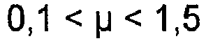
- Verfahren nach einem der vorangegangenen Ansprüche,
dadurch gekennzeichnet,
dass für die Dicke d der Zunderschicht gilt:
- Verfahren nach einem der vorangegangenen Ansprüche,dadurch gekennzeichnet,dass für die Temperatur T des warmen Metallproduktes gilt:800°C < T < 1250°C, vorzugsweise 900°C < T < 1160°C.
- Verfahren nach einem der vorangegangenen Ansprüche,
dadurch gekennzeichnet,
dass das Aufbringen der Zunderschicht mit der vorbestimmten Dicke erfolgt, indem die Stirnseiten der Metallprodukte unmittelbar nach dem Schopfschnitt für eine vorbestimmte Zeitdauer t mit t<60s, vorzugsweise t<15s der Umgebungsluft, einer Druckluftbeaufschlagung oder einem oxidierenden Gas, zum Beispiel einem Gemisch aus Stickstoff und Sauerstoff mit einem geringeren Sauerstoffgehalt als Luft, ausgesetzt werden, bevor sie miteinander reibverschweißt werden. - Verfahren nach einem der vorangegangenen Ansprüche,
dadurch gekennzeichnet,
dass die warmen Metallprodukte, nachdem sie miteinander verschweißt wurden, warmgewalzt werden.
Applications Claiming Priority (3)
| Application Number | Priority Date | Filing Date | Title |
|---|---|---|---|
| DE102018220218 | 2018-11-26 | ||
| DE102019214295.8A DE102019214295A1 (de) | 2018-11-26 | 2019-09-19 | Verfahren zum Verschweißen zweier Brammen |
| PCT/EP2019/081526 WO2020109035A1 (de) | 2018-11-26 | 2019-11-15 | Verfahren zum reibschweissen zweier warmer metallprodukte |
Publications (2)
| Publication Number | Publication Date |
|---|---|
| EP3887086A1 EP3887086A1 (de) | 2021-10-06 |
| EP3887086B1 true EP3887086B1 (de) | 2022-10-19 |
Family
ID=68653452
Family Applications (1)
| Application Number | Title | Priority Date | Filing Date |
|---|---|---|---|
| EP19808551.6A Active EP3887086B1 (de) | 2018-11-26 | 2019-11-15 | Verfahren zum reibschweissen zweier warmer metallprodukte |
Country Status (4)
| Country | Link |
|---|---|
| EP (1) | EP3887086B1 (de) |
| JP (1) | JP7111898B2 (de) |
| DE (1) | DE102019214295A1 (de) |
| WO (1) | WO2020109035A1 (de) |
Families Citing this family (2)
| Publication number | Priority date | Publication date | Assignee | Title |
|---|---|---|---|---|
| DE102020214578A1 (de) | 2020-03-27 | 2021-09-30 | Sms Group Gmbh | Vorrichtung und Verfahren zum Reibschweißen metallischer Strangprodukte |
| DE102021207912A1 (de) * | 2021-07-23 | 2023-01-26 | Sms Group Gmbh | Verfahren zum Herstellen eines Coils metallischen Bandes |
Family Cites Families (12)
| Publication number | Priority date | Publication date | Assignee | Title |
|---|---|---|---|---|
| DE932303C (de) * | 1954-03-18 | 1955-08-29 | Schloemann Ag | Walzenstrasse zum kontinuierlichen Auswalzen von Walzstaeben beliebiger Laenge |
| KR950011312B1 (ko) | 1990-10-05 | 1995-09-30 | 수미도모 메탈 인더스트리에스 리미티드 | 강재의 열간 접합방법 |
| EP0492368B1 (de) | 1990-12-20 | 1996-05-08 | Mitsubishi Jukogyo Kabushiki Kaisha | Vorrichtung zum Stumpfstossverbinden laufender Stahlbleche |
| DE69206188T2 (de) | 1991-04-26 | 1996-03-28 | Hitachi Ltd | Verfahren und Einrichtung zum Verbinden erwärmter Bänder. |
| US5217155A (en) | 1991-08-16 | 1993-06-08 | Kawasaki Steel Corporation | Method of continuously hot-rolling sheet bars |
| DE69628648T2 (de) | 1996-03-04 | 2004-04-08 | Nippon Steel Corp. | Verfahren zum kontinuierlichen warmwalzen |
| JP3501914B2 (ja) | 1997-02-21 | 2004-03-02 | 住友金属工業株式会社 | 鋼材の熱間圧接方法 |
| JPH11147101A (ja) * | 1997-11-11 | 1999-06-02 | Kawasaki Steel Corp | プレス成形性および耐型かじり性に優れる熱延鋼板ならびにその製造方法 |
| EP1136580B1 (de) | 1999-08-19 | 2007-02-21 | Nippon Steel Corporation | Verwendung eines stahles zum laserschweissen |
| JP4230651B2 (ja) * | 1999-12-14 | 2009-02-25 | 株式会社日立製作所 | 金属板の接合方法、接合装置及び熱間圧延設備 |
| JP2005262286A (ja) * | 2004-03-19 | 2005-09-29 | Jfe Steel Kk | オンラインロールグラインダを備えた熱間仕上圧延機列および熱間圧延機列 |
| WO2017140886A1 (de) * | 2016-02-17 | 2017-08-24 | Sms Group Gmbh | Vorrichtung und verfahren zum reibverschweissen warmer metallischer produkte |
-
2019
- 2019-09-19 DE DE102019214295.8A patent/DE102019214295A1/de active Pending
- 2019-11-15 WO PCT/EP2019/081526 patent/WO2020109035A1/de not_active Ceased
- 2019-11-15 JP JP2021521364A patent/JP7111898B2/ja active Active
- 2019-11-15 EP EP19808551.6A patent/EP3887086B1/de active Active
Also Published As
| Publication number | Publication date |
|---|---|
| JP2022505367A (ja) | 2022-01-14 |
| WO2020109035A1 (de) | 2020-06-04 |
| EP3887086A1 (de) | 2021-10-06 |
| JP7111898B2 (ja) | 2022-08-02 |
| DE102019214295A1 (de) | 2020-05-28 |
Similar Documents
| Publication | Publication Date | Title |
|---|---|---|
| DE10237763B4 (de) | Verfahren zur Herstellung unlösbarer stoffschlüssiger Verbindungen von Bauteilen aus oxid-dispergierten-(ODS)-metallischen Werkstoffen durch Verschweißen und durch das Verfahren hergestellte Bauteile | |
| DE102008036435B4 (de) | Verfahren und Vorrichtung zum Herstellen von metallischen Werkstoffverbunden und Verbund-Halbzeugen | |
| DE69114467T2 (de) | Verfahren zum verbinden von knüppeln beim warmwalzen und verfahren zum kontinuierlichen warmwalzen. | |
| WO2017140891A1 (de) | Endloswalzen in einer mehr-strang-csp-anlage | |
| EP0805733B1 (de) | Laserunterstütztes plattieren von band | |
| EP1442820B1 (de) | Verfahren zum Verbinden von wenigstens zwei aneinanderliegenden Werkstücken nach der Methode des Reibrührschweissens | |
| EP2090395A2 (de) | Verfahren und Vorrichtung zum Herstellen von metallischen Werkstoffverbunden und Verbund-Halbzeugen | |
| WO2017167964A1 (de) | Rührreibschweissverfahren, -stift und -bearbeitungsvorrichtung zum verbinden von bauteilen aus unterschiedlichen materialien : entsprechende schweissverbindung | |
| EP3664943A1 (de) | VORRICHTUNG UND VERFAHREN ZUM REIBSCHWEIßEN WARMER METALLISCHER PRODUKTE | |
| EP3188867B1 (de) | Verfahren zur herstellung eines vormaterials für ein zerspanungswerkzeug | |
| EP2489459A1 (de) | Verfahren und Vorrichtung zum Verschweißen von Bauteilen mittels eines Laserstrahls | |
| WO2020109035A1 (de) | Verfahren zum reibschweissen zweier warmer metallprodukte | |
| DE202012102318U1 (de) | Fügeverbindung zwischen metallischen Bauteilen und Schweißvorrichtung | |
| DE112006003562B4 (de) | Verfahren zum Verbinden hoch-kohlenstoffhaltigen Stahls zum Endlos-Warmwalzen | |
| DE102004036531B4 (de) | Warmwalzvorrichtung | |
| EP3010678B1 (de) | Schweisseinrichtung und schweissverfahren zum schweissen von werkstücken mit einem umlaufend bewegten lichtbogen unter erwärmen der werkstücke nach dem schweissen | |
| DE3824698C2 (de) | Verfahren und Einrichtung zum Stoßverbinden von Metallbahnen oder -bändern | |
| EP3600755B1 (de) | Verfahren zum stirnseitigen laserschweissen | |
| DE3401670A1 (de) | Verfahren und einrichtung zum verbinden zweier metallschichten, insbesondere zum plattieren | |
| DE102004002504B4 (de) | Verfahren zum gratfreien Trennen von Halbzeug aus duktilem Material und dessen Verwendung | |
| DE19621259A1 (de) | Verfahren und Anlage zur Herstellung von Edelstahl- oder Kohlenstoffstahlblech aus durch Strangguß erzeugten Dünnbrammen | |
| DE202021101463U1 (de) | Lasergeschweißte Schweißkonstruktion | |
| DE69628648T2 (de) | Verfahren zum kontinuierlichen warmwalzen | |
| DE102015116191A1 (de) | Verfahren zur umforminduzierten Schweißnahtbehandlung | |
| DE102017129237A1 (de) | Verfahren und Vorrichtung zum Schneiden eines Werkstücks |
Legal Events
| Date | Code | Title | Description |
|---|---|---|---|
| STAA | Information on the status of an ep patent application or granted ep patent |
Free format text: STATUS: UNKNOWN |
|
| STAA | Information on the status of an ep patent application or granted ep patent |
Free format text: STATUS: THE INTERNATIONAL PUBLICATION HAS BEEN MADE |
|
| PUAI | Public reference made under article 153(3) epc to a published international application that has entered the european phase |
Free format text: ORIGINAL CODE: 0009012 |
|
| STAA | Information on the status of an ep patent application or granted ep patent |
Free format text: STATUS: REQUEST FOR EXAMINATION WAS MADE |
|
| 17P | Request for examination filed |
Effective date: 20210628 |
|
| AK | Designated contracting states |
Kind code of ref document: A1 Designated state(s): AL AT BE BG CH CY CZ DE DK EE ES FI FR GB GR HR HU IE IS IT LI LT LU LV MC MK MT NL NO PL PT RO RS SE SI SK SM TR |
|
| DAV | Request for validation of the european patent (deleted) | ||
| DAX | Request for extension of the european patent (deleted) | ||
| GRAP | Despatch of communication of intention to grant a patent |
Free format text: ORIGINAL CODE: EPIDOSNIGR1 |
|
| STAA | Information on the status of an ep patent application or granted ep patent |
Free format text: STATUS: GRANT OF PATENT IS INTENDED |
|
| INTG | Intention to grant announced |
Effective date: 20220607 |
|
| GRAS | Grant fee paid |
Free format text: ORIGINAL CODE: EPIDOSNIGR3 |
|
| GRAA | (expected) grant |
Free format text: ORIGINAL CODE: 0009210 |
|
| STAA | Information on the status of an ep patent application or granted ep patent |
Free format text: STATUS: THE PATENT HAS BEEN GRANTED |
|
| AK | Designated contracting states |
Kind code of ref document: B1 Designated state(s): AL AT BE BG CH CY CZ DE DK EE ES FI FR GB GR HR HU IE IS IT LI LT LU LV MC MK MT NL NO PL PT RO RS SE SI SK SM TR |
|
| REG | Reference to a national code |
Ref country code: GB Ref legal event code: FG4D Free format text: NOT ENGLISH |
|
| REG | Reference to a national code |
Ref country code: CH Ref legal event code: EP |
|
| REG | Reference to a national code |
Ref country code: DE Ref legal event code: R096 Ref document number: 502019005990 Country of ref document: DE |
|
| REG | Reference to a national code |
Ref country code: IE Ref legal event code: FG4D Free format text: LANGUAGE OF EP DOCUMENT: GERMAN |
|
| REG | Reference to a national code |
Ref country code: AT Ref legal event code: REF Ref document number: 1525259 Country of ref document: AT Kind code of ref document: T Effective date: 20221115 |
|
| REG | Reference to a national code |
Ref country code: LT Ref legal event code: MG9D |
|
| REG | Reference to a national code |
Ref country code: NL Ref legal event code: MP Effective date: 20221019 |
|
| PG25 | Lapsed in a contracting state [announced via postgrant information from national office to epo] |
Ref country code: NL Free format text: LAPSE BECAUSE OF FAILURE TO SUBMIT A TRANSLATION OF THE DESCRIPTION OR TO PAY THE FEE WITHIN THE PRESCRIBED TIME-LIMIT Effective date: 20221019 |
|
| PG25 | Lapsed in a contracting state [announced via postgrant information from national office to epo] |
Ref country code: SE Free format text: LAPSE BECAUSE OF FAILURE TO SUBMIT A TRANSLATION OF THE DESCRIPTION OR TO PAY THE FEE WITHIN THE PRESCRIBED TIME-LIMIT Effective date: 20221019 Ref country code: PT Free format text: LAPSE BECAUSE OF FAILURE TO SUBMIT A TRANSLATION OF THE DESCRIPTION OR TO PAY THE FEE WITHIN THE PRESCRIBED TIME-LIMIT Effective date: 20230220 Ref country code: NO Free format text: LAPSE BECAUSE OF FAILURE TO SUBMIT A TRANSLATION OF THE DESCRIPTION OR TO PAY THE FEE WITHIN THE PRESCRIBED TIME-LIMIT Effective date: 20230119 Ref country code: LT Free format text: LAPSE BECAUSE OF FAILURE TO SUBMIT A TRANSLATION OF THE DESCRIPTION OR TO PAY THE FEE WITHIN THE PRESCRIBED TIME-LIMIT Effective date: 20221019 Ref country code: FI Free format text: LAPSE BECAUSE OF FAILURE TO SUBMIT A TRANSLATION OF THE DESCRIPTION OR TO PAY THE FEE WITHIN THE PRESCRIBED TIME-LIMIT Effective date: 20221019 Ref country code: ES Free format text: LAPSE BECAUSE OF FAILURE TO SUBMIT A TRANSLATION OF THE DESCRIPTION OR TO PAY THE FEE WITHIN THE PRESCRIBED TIME-LIMIT Effective date: 20221019 |
|
| PG25 | Lapsed in a contracting state [announced via postgrant information from national office to epo] |
Ref country code: RS Free format text: LAPSE BECAUSE OF FAILURE TO SUBMIT A TRANSLATION OF THE DESCRIPTION OR TO PAY THE FEE WITHIN THE PRESCRIBED TIME-LIMIT Effective date: 20221019 Ref country code: PL Free format text: LAPSE BECAUSE OF FAILURE TO SUBMIT A TRANSLATION OF THE DESCRIPTION OR TO PAY THE FEE WITHIN THE PRESCRIBED TIME-LIMIT Effective date: 20221019 Ref country code: LV Free format text: LAPSE BECAUSE OF FAILURE TO SUBMIT A TRANSLATION OF THE DESCRIPTION OR TO PAY THE FEE WITHIN THE PRESCRIBED TIME-LIMIT Effective date: 20221019 Ref country code: IS Free format text: LAPSE BECAUSE OF FAILURE TO SUBMIT A TRANSLATION OF THE DESCRIPTION OR TO PAY THE FEE WITHIN THE PRESCRIBED TIME-LIMIT Effective date: 20230219 Ref country code: HR Free format text: LAPSE BECAUSE OF FAILURE TO SUBMIT A TRANSLATION OF THE DESCRIPTION OR TO PAY THE FEE WITHIN THE PRESCRIBED TIME-LIMIT Effective date: 20221019 Ref country code: GR Free format text: LAPSE BECAUSE OF FAILURE TO SUBMIT A TRANSLATION OF THE DESCRIPTION OR TO PAY THE FEE WITHIN THE PRESCRIBED TIME-LIMIT Effective date: 20230120 |
|
| REG | Reference to a national code |
Ref country code: CH Ref legal event code: PL |
|
| REG | Reference to a national code |
Ref country code: DE Ref legal event code: R097 Ref document number: 502019005990 Country of ref document: DE |
|
| REG | Reference to a national code |
Ref country code: BE Ref legal event code: MM Effective date: 20221130 |
|
| PG25 | Lapsed in a contracting state [announced via postgrant information from national office to epo] |
Ref country code: SM Free format text: LAPSE BECAUSE OF FAILURE TO SUBMIT A TRANSLATION OF THE DESCRIPTION OR TO PAY THE FEE WITHIN THE PRESCRIBED TIME-LIMIT Effective date: 20221019 Ref country code: RO Free format text: LAPSE BECAUSE OF FAILURE TO SUBMIT A TRANSLATION OF THE DESCRIPTION OR TO PAY THE FEE WITHIN THE PRESCRIBED TIME-LIMIT Effective date: 20221019 Ref country code: MC Free format text: LAPSE BECAUSE OF FAILURE TO SUBMIT A TRANSLATION OF THE DESCRIPTION OR TO PAY THE FEE WITHIN THE PRESCRIBED TIME-LIMIT Effective date: 20221019 Ref country code: LI Free format text: LAPSE BECAUSE OF NON-PAYMENT OF DUE FEES Effective date: 20221130 Ref country code: IT Free format text: LAPSE BECAUSE OF NON-PAYMENT OF DUE FEES Effective date: 20221115 Ref country code: EE Free format text: LAPSE BECAUSE OF FAILURE TO SUBMIT A TRANSLATION OF THE DESCRIPTION OR TO PAY THE FEE WITHIN THE PRESCRIBED TIME-LIMIT Effective date: 20221019 Ref country code: DK Free format text: LAPSE BECAUSE OF FAILURE TO SUBMIT A TRANSLATION OF THE DESCRIPTION OR TO PAY THE FEE WITHIN THE PRESCRIBED TIME-LIMIT Effective date: 20221019 Ref country code: CZ Free format text: LAPSE BECAUSE OF FAILURE TO SUBMIT A TRANSLATION OF THE DESCRIPTION OR TO PAY THE FEE WITHIN THE PRESCRIBED TIME-LIMIT Effective date: 20221019 Ref country code: CH Free format text: LAPSE BECAUSE OF NON-PAYMENT OF DUE FEES Effective date: 20221130 |
|
| P01 | Opt-out of the competence of the unified patent court (upc) registered |
Effective date: 20230707 |
|
| PLBE | No opposition filed within time limit |
Free format text: ORIGINAL CODE: 0009261 |
|
| STAA | Information on the status of an ep patent application or granted ep patent |
Free format text: STATUS: NO OPPOSITION FILED WITHIN TIME LIMIT |
|
| PG25 | Lapsed in a contracting state [announced via postgrant information from national office to epo] |
Ref country code: SK Free format text: LAPSE BECAUSE OF FAILURE TO SUBMIT A TRANSLATION OF THE DESCRIPTION OR TO PAY THE FEE WITHIN THE PRESCRIBED TIME-LIMIT Effective date: 20221019 Ref country code: LU Free format text: LAPSE BECAUSE OF NON-PAYMENT OF DUE FEES Effective date: 20221115 Ref country code: AL Free format text: LAPSE BECAUSE OF FAILURE TO SUBMIT A TRANSLATION OF THE DESCRIPTION OR TO PAY THE FEE WITHIN THE PRESCRIBED TIME-LIMIT Effective date: 20221019 |
|
| 26N | No opposition filed |
Effective date: 20230720 |
|
| PG25 | Lapsed in a contracting state [announced via postgrant information from national office to epo] |
Ref country code: IE Free format text: LAPSE BECAUSE OF NON-PAYMENT OF DUE FEES Effective date: 20221115 |
|
| PG25 | Lapsed in a contracting state [announced via postgrant information from national office to epo] |
Ref country code: SI Free format text: LAPSE BECAUSE OF FAILURE TO SUBMIT A TRANSLATION OF THE DESCRIPTION OR TO PAY THE FEE WITHIN THE PRESCRIBED TIME-LIMIT Effective date: 20221019 Ref country code: FR Free format text: LAPSE BECAUSE OF NON-PAYMENT OF DUE FEES Effective date: 20221219 Ref country code: BE Free format text: LAPSE BECAUSE OF NON-PAYMENT OF DUE FEES Effective date: 20221130 |
|
| PG25 | Lapsed in a contracting state [announced via postgrant information from national office to epo] |
Ref country code: IT Free format text: LAPSE BECAUSE OF NON-PAYMENT OF DUE FEES Effective date: 20221115 |
|
| PGRI | Patent reinstated in contracting state [announced from national office to epo] |
Ref country code: IT Effective date: 20221130 |
|
| PG25 | Lapsed in a contracting state [announced via postgrant information from national office to epo] |
Ref country code: CY Free format text: LAPSE BECAUSE OF FAILURE TO SUBMIT A TRANSLATION OF THE DESCRIPTION OR TO PAY THE FEE WITHIN THE PRESCRIBED TIME-LIMIT Effective date: 20221019 |
|
| PG25 | Lapsed in a contracting state [announced via postgrant information from national office to epo] |
Ref country code: MK Free format text: LAPSE BECAUSE OF FAILURE TO SUBMIT A TRANSLATION OF THE DESCRIPTION OR TO PAY THE FEE WITHIN THE PRESCRIBED TIME-LIMIT Effective date: 20221019 Ref country code: HU Free format text: LAPSE BECAUSE OF FAILURE TO SUBMIT A TRANSLATION OF THE DESCRIPTION OR TO PAY THE FEE WITHIN THE PRESCRIBED TIME-LIMIT; INVALID AB INITIO Effective date: 20191115 |
|
| PG25 | Lapsed in a contracting state [announced via postgrant information from national office to epo] |
Ref country code: TR Free format text: LAPSE BECAUSE OF FAILURE TO SUBMIT A TRANSLATION OF THE DESCRIPTION OR TO PAY THE FEE WITHIN THE PRESCRIBED TIME-LIMIT Effective date: 20221019 |
|
| GBPC | Gb: european patent ceased through non-payment of renewal fee |
Effective date: 20231115 |
|
| PG25 | Lapsed in a contracting state [announced via postgrant information from national office to epo] |
Ref country code: BG Free format text: LAPSE BECAUSE OF FAILURE TO SUBMIT A TRANSLATION OF THE DESCRIPTION OR TO PAY THE FEE WITHIN THE PRESCRIBED TIME-LIMIT Effective date: 20221019 |
|
| PG25 | Lapsed in a contracting state [announced via postgrant information from national office to epo] |
Ref country code: MT Free format text: LAPSE BECAUSE OF FAILURE TO SUBMIT A TRANSLATION OF THE DESCRIPTION OR TO PAY THE FEE WITHIN THE PRESCRIBED TIME-LIMIT Effective date: 20221019 |
|
| PG25 | Lapsed in a contracting state [announced via postgrant information from national office to epo] |
Ref country code: GB Free format text: LAPSE BECAUSE OF NON-PAYMENT OF DUE FEES Effective date: 20231115 |
|
| PG25 | Lapsed in a contracting state [announced via postgrant information from national office to epo] |
Ref country code: GB Free format text: LAPSE BECAUSE OF NON-PAYMENT OF DUE FEES Effective date: 20231115 |
|
| PGFP | Annual fee paid to national office [announced via postgrant information from national office to epo] |
Ref country code: DE Payment date: 20251119 Year of fee payment: 7 |
|
| PGFP | Annual fee paid to national office [announced via postgrant information from national office to epo] |
Ref country code: AT Payment date: 20251120 Year of fee payment: 7 |
|
| PGFP | Annual fee paid to national office [announced via postgrant information from national office to epo] |
Ref country code: IT Payment date: 20251125 Year of fee payment: 7 |