EP3886459B1 - Schallerzeugungsvorrichtung, frequenzweiche und schallerzeugungszelle dafür - Google Patents
Schallerzeugungsvorrichtung, frequenzweiche und schallerzeugungszelle dafür Download PDFInfo
- Publication number
- EP3886459B1 EP3886459B1 EP21154023.2A EP21154023A EP3886459B1 EP 3886459 B1 EP3886459 B1 EP 3886459B1 EP 21154023 A EP21154023 A EP 21154023A EP 3886459 B1 EP3886459 B1 EP 3886459B1
- Authority
- EP
- European Patent Office
- Prior art keywords
- membrane
- driving signal
- spd
- sound producing
- resonance frequency
- Prior art date
- Legal status (The legal status is an assumption and is not a legal conclusion. Google has not performed a legal analysis and makes no representation as to the accuracy of the status listed.)
- Active
Links
Images


Classifications
-
- H—ELECTRICITY
- H04—ELECTRIC COMMUNICATION TECHNIQUE
- H04R—LOUDSPEAKERS, MICROPHONES, GRAMOPHONE PICK-UPS OR LIKE ACOUSTIC ELECTROMECHANICAL TRANSDUCERS; ELECTRIC HEARING AIDS; PUBLIC ADDRESS SYSTEMS
- H04R1/00—Details of transducers, loudspeakers or microphones
- H04R1/20—Arrangements for obtaining desired frequency or directional characteristics
- H04R1/22—Arrangements for obtaining desired frequency or directional characteristics for obtaining desired frequency characteristic only
- H04R1/26—Spatial arrangements of separate transducers responsive to two or more frequency ranges
-
- H—ELECTRICITY
- H04—ELECTRIC COMMUNICATION TECHNIQUE
- H04R—LOUDSPEAKERS, MICROPHONES, GRAMOPHONE PICK-UPS OR LIKE ACOUSTIC ELECTROMECHANICAL TRANSDUCERS; ELECTRIC HEARING AIDS; PUBLIC ADDRESS SYSTEMS
- H04R3/00—Circuits for transducers
- H04R3/12—Circuits for transducers for distributing signals to two or more loudspeakers
- H04R3/14—Cross-over networks
-
- B—PERFORMING OPERATIONS; TRANSPORTING
- B81—MICROSTRUCTURAL TECHNOLOGY
- B81B—MICROSTRUCTURAL DEVICES OR SYSTEMS, e.g. MICROMECHANICAL DEVICES
- B81B3/00—Devices comprising flexible or deformable elements, e.g. comprising elastic tongues or membranes
- B81B3/0018—Structures acting upon the moving or flexible element for transforming energy into mechanical movement or vice versa, i.e. actuators, sensors, generators
- B81B3/0021—Transducers for transforming electrical into mechanical energy or vice versa
-
- G—PHYSICS
- G10—MUSICAL INSTRUMENTS; ACOUSTICS
- G10K—SOUND-PRODUCING DEVICES; METHODS OR DEVICES FOR PROTECTING AGAINST, OR FOR DAMPING, NOISE OR OTHER ACOUSTIC WAVES IN GENERAL; ACOUSTICS NOT OTHERWISE PROVIDED FOR
- G10K11/00—Methods or devices for transmitting, conducting or directing sound in general; Methods or devices for protecting against, or for damping, noise or other acoustic waves in general
- G10K11/16—Methods or devices for protecting against, or for damping, noise or other acoustic waves in general
- G10K11/175—Methods or devices for protecting against, or for damping, noise or other acoustic waves in general using interference effects; Masking sound
- G10K11/178—Methods or devices for protecting against, or for damping, noise or other acoustic waves in general using interference effects; Masking sound by electro-acoustically regenerating the original acoustic waves in anti-phase
-
- G—PHYSICS
- G10—MUSICAL INSTRUMENTS; ACOUSTICS
- G10K—SOUND-PRODUCING DEVICES; METHODS OR DEVICES FOR PROTECTING AGAINST, OR FOR DAMPING, NOISE OR OTHER ACOUSTIC WAVES IN GENERAL; ACOUSTICS NOT OTHERWISE PROVIDED FOR
- G10K15/00—Acoustics not otherwise provided for
- G10K15/02—Synthesis of acoustic waves
-
- G—PHYSICS
- G10—MUSICAL INSTRUMENTS; ACOUSTICS
- G10K—SOUND-PRODUCING DEVICES; METHODS OR DEVICES FOR PROTECTING AGAINST, OR FOR DAMPING, NOISE OR OTHER ACOUSTIC WAVES IN GENERAL; ACOUSTICS NOT OTHERWISE PROVIDED FOR
- G10K9/00—Devices in which sound is produced by vibrating a diaphragm or analogous element, e.g. fog horns, vehicle hooters or buzzers
- G10K9/18—Details, e.g. bulbs, pumps, pistons, switches or casings
- G10K9/20—Sounding members
-
- H—ELECTRICITY
- H04—ELECTRIC COMMUNICATION TECHNIQUE
- H04R—LOUDSPEAKERS, MICROPHONES, GRAMOPHONE PICK-UPS OR LIKE ACOUSTIC ELECTROMECHANICAL TRANSDUCERS; ELECTRIC HEARING AIDS; PUBLIC ADDRESS SYSTEMS
- H04R1/00—Details of transducers, loudspeakers or microphones
- H04R1/10—Earpieces; Attachments therefor ; Earphones; Monophonic headphones
- H04R1/1058—Manufacture or assembly
- H04R1/1075—Mountings of transducers in earphones or headphones
-
- H—ELECTRICITY
- H04—ELECTRIC COMMUNICATION TECHNIQUE
- H04R—LOUDSPEAKERS, MICROPHONES, GRAMOPHONE PICK-UPS OR LIKE ACOUSTIC ELECTROMECHANICAL TRANSDUCERS; ELECTRIC HEARING AIDS; PUBLIC ADDRESS SYSTEMS
- H04R17/00—Piezoelectric transducers; Electrostrictive transducers
-
- H—ELECTRICITY
- H04—ELECTRIC COMMUNICATION TECHNIQUE
- H04R—LOUDSPEAKERS, MICROPHONES, GRAMOPHONE PICK-UPS OR LIKE ACOUSTIC ELECTROMECHANICAL TRANSDUCERS; ELECTRIC HEARING AIDS; PUBLIC ADDRESS SYSTEMS
- H04R19/00—Electrostatic transducers
- H04R19/02—Loudspeakers
-
- H—ELECTRICITY
- H04—ELECTRIC COMMUNICATION TECHNIQUE
- H04R—LOUDSPEAKERS, MICROPHONES, GRAMOPHONE PICK-UPS OR LIKE ACOUSTIC ELECTROMECHANICAL TRANSDUCERS; ELECTRIC HEARING AIDS; PUBLIC ADDRESS SYSTEMS
- H04R7/00—Diaphragms for electromechanical transducers; Cones
- H04R7/02—Diaphragms for electromechanical transducers; Cones characterised by the construction
- H04R7/04—Plane diaphragms
-
- B—PERFORMING OPERATIONS; TRANSPORTING
- B81—MICROSTRUCTURAL TECHNOLOGY
- B81B—MICROSTRUCTURAL DEVICES OR SYSTEMS, e.g. MICROMECHANICAL DEVICES
- B81B2201/00—Specific applications of microelectromechanical systems
- B81B2201/02—Sensors
- B81B2201/0257—Microphones or microspeakers
-
- B—PERFORMING OPERATIONS; TRANSPORTING
- B81—MICROSTRUCTURAL TECHNOLOGY
- B81B—MICROSTRUCTURAL DEVICES OR SYSTEMS, e.g. MICROMECHANICAL DEVICES
- B81B2203/00—Basic microelectromechanical structures
- B81B2203/01—Suspended structures, i.e. structures allowing a movement
- B81B2203/0127—Diaphragms, i.e. structures separating two media that can control the passage from one medium to another; Membranes, i.e. diaphragms with filtering function
-
- B—PERFORMING OPERATIONS; TRANSPORTING
- B81—MICROSTRUCTURAL TECHNOLOGY
- B81B—MICROSTRUCTURAL DEVICES OR SYSTEMS, e.g. MICROMECHANICAL DEVICES
- B81B2207/00—Microstructural systems or auxiliary parts thereof
- B81B2207/03—Electronic circuits for micromechanical devices which are not application specific, e.g. for controlling, power supplying, testing, protecting
-
- G—PHYSICS
- G10—MUSICAL INSTRUMENTS; ACOUSTICS
- G10K—SOUND-PRODUCING DEVICES; METHODS OR DEVICES FOR PROTECTING AGAINST, OR FOR DAMPING, NOISE OR OTHER ACOUSTIC WAVES IN GENERAL; ACOUSTICS NOT OTHERWISE PROVIDED FOR
- G10K2210/00—Details of active noise control [ANC] covered by G10K11/178 but not provided for in any of its subgroups
- G10K2210/10—Applications
- G10K2210/108—Communication systems, e.g. where useful sound is kept and noise is cancelled
- G10K2210/1081—Earphones, e.g. for telephones, ear protectors or headsets
-
- H—ELECTRICITY
- H04—ELECTRIC COMMUNICATION TECHNIQUE
- H04R—LOUDSPEAKERS, MICROPHONES, GRAMOPHONE PICK-UPS OR LIKE ACOUSTIC ELECTROMECHANICAL TRANSDUCERS; ELECTRIC HEARING AIDS; PUBLIC ADDRESS SYSTEMS
- H04R2201/00—Details of transducers, loudspeakers or microphones covered by H04R1/00 but not provided for in any of its subgroups
- H04R2201/003—Mems transducers or their use
Definitions
- the present application relates to a sound producing device, and more particularly, to a sound producing device capable of enhancing design flexibility and/or sound quality.
- a Micro Electro Mechanical System (MEMS) speaker normally employs only one type of membrane to cover the entire audible/hearing range, and therefore the maximum input frequency of an input signal generally equals the maximum human audible frequency, which is typically about 15-17 Kilohertz (KHz) for adults. These can limit the design flexibility and/or sound quality of a MEMS speaker.
- KHz Kilohertz
- a sound producing cell comprising a membrane comprising a first membrane subpart and a second membrane subpart; wherein only one edge of each of the first membrane subpart and the second membrane subpart is anchored, and other edges of each of the first membrane subpart and the second membrane subpart are released.
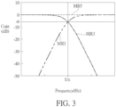
- FIG. 3 is a schematic diagram of the amplitude frequency response corresponding to the crossover circuit 290.
- the frequency response MR1 of the HPF 501 and the frequency response MR3 of the LPF 503 intersect at a crossover frequency fcx at their respective -6dB points.
- the crossover frequency fcx may, or preferably, fall between 800Hz to 4KHz, approximately the range of the frequency where human hearing is the most sensitive, so as to divide the workload of sound production equitably between cells 110 and cells 130.
- the HPF 501 and the LPF 503 both have -6 decibel (dB) roll-off at the cross-over frequency fcx.
- dB decibel
- the crossover circuit 290 may further includes a gain circuit (or sensitivity compensation block) 502 configured to compensate for difference in the sensitivities between the sound producing cells 110, 130.
- a gain circuit or sensitivity compensation block 502 configured to compensate for difference in the sensitivities between the sound producing cells 110, 130.
- each membrane 130M is larger than that of each membrane 110M, resulting in the resonance frequency of the membrane 130M being lower than that of the membrane 110M.
- the sound producing cell 110 may further include at least one actuator 110T attached/disposed on the membrane 110M.
- the actuator 110T may be a thin film actuator such as a piezoelectric actuator, which includes electrodes 111, 113 and a material 112 (e.g., piezoelectric material) sandwiched between the electrodes 111, 113.
- the material 112 may be made of thin-film piezoelectric material(s) such as PZT (lead zirconate titanate).
- the driving signal S110 is applied across the electrodes 111 and 113 to cause the deformation of the material 112, such that the membrane 110M deforms to produce movement in the Z direction and generate the (acoustic) sound/pressure P110.
- the SPD 10 includes the (2-way) cell array 100 where multiple membrane designs may be employed to cover the overall frequency spectrum to be produced by the SPD 10.
- the sound producing cells 110 and 130 may be driven by the output of the crossover circuit 190, which partitions the frequency spectrum of the input signal Sn into two (or more) complementary audio bands.
- the cross-over frequency fcx and the resonance frequencies f r,110 and f r,130 have a relation of fcx ⁇ f r,130 ⁇ f r,110 (eq. 1).
- f max,S110 denotes a maximum frequency of the driving signal S110 (e.g., 15 KHz or 20 KHz)
- the relation in eq. 1 may be further extended to fcx ⁇ f r,130 ⁇ f max,S110 ⁇ f r,110 (eq. 2).
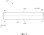
- FIG. 6 is a schematic diagram of a top view of a membrane pattern (representing a sound producing cell) 610P1 according to an embodiment of the present application.
- the membrane pattern 610P1 also represents embodiments of sound producing cells of the present application.
- a membrane (e.g., the membrane 110M) within the sound producing cell 610P1 may be divided into two membrane subparts 411 and 412 to form the membrane pattern 610P1 having reflection symmetry.
- the membrane subparts 411, 412 may swing upwards/downwards as the flaps/leaves of a bascule bridge according to the driving signal (e.g., the driving signals S110) applied to the actuator(s) (e.g., the actuator 110T) on the membrane.
- the membrane subparts 411, 412 may move up and down in the Z direction synchronously to avoid big gap(s) disjointing between the membrane subparts 411, 412 from being formed.
- the membrane subparts 411, 412 may be actuated to move toward the same direction.
- the slit segment 415 is formed between the membrane subpart 411 and the membrane subpart 412, parallel to the long edges of membrane subpart 411/412.
- the slit segments 413 coincide with membrane boundary along the short edges of membrane subparts 411/412.
- FIG. 7 is a schematic diagram illustrating a top view of a sound generating/producing cell array 700 according to an embodiment of the present application.
- the cell array 700 may include one sound producing (tweeter) cell 410, receiving driving signal S110, and four (woofer) cells 130, surrounding the tweeter cell 410.
- the cell 410 may adopt the membrane pattern 610P1 shown in FIG. 6
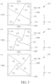
- woofer cells 130 may adopt membrane pattern such as 330 or 320 shown in FIG.5 or other membrane pattern suitable for producing low frequency sound.
- the short side of the sound producing (tweeter) cell 410 may be beneficial for obtaining higher resonant frequency
- the long side of the sound producing (tweeter) cell 410 may be beneficial for enlarging SPL.
- the cell 410 with large aspect ratio, a ratio of a length of the long side thereof with respect to a length of the short side may achieve both higher resonant frequency and the larger SPL, compared to the cell with less aspect ratio.
- the tweeter cell 410 with high aspect ratio may help reducing an area of the cell array 700.
- the aspect ratio for the tweeter cell may depend on practical requirement. As long as the aspect ratio is larger than 2, the requirement of the present application is satisfied, which is within the scope of the present application.
- a low-pass BiQuad IIR filter may be implemented by suitable alternatives such as those introduced in U.S. provisional application No. 63/079,680 , which is incorporated herein by reference, with 6 addition operations and 2 registers per stage without any multiplication, where the register(s) serve/function as storage unit(s)/circuit(s), and one register may represent one storage unit/circuit.
- this LPF portion of the crossover circuit (or filter(s) therein) may comprise no multiplication circuit.
- the crossover circuit 890A shown in FIG. 8a may include the LPF 503 configured to output the driving signal S130 for the (woofer) cell 130, while replacing the HPF 501 of FIG. 2 by the subtraction circuit (or subtracter/subtractor) 506 of the crossover circuit 890A.
- the subtraction circuit 506 is configured to deduct the driving signal S130 from the input signal Sn to obtain a signal corresponding to the driving signal S110 for the cell 110.
- there is no phase difference between the sum of the output of the crossover circuit 890A (namely, the sum of driving signals S130 and S110) and the input signal Sn, i.e., S110 + S130 Sn,.
- This Zero-phase-shift feature is greatly beneficial to active-noise cancelling (ANC), as any delay can lead to phase misalignment and degrade the efficacy of an ANC circuit.
- the phase response is as critical as the amplitude response, and a flat amplitude response alone is not enough to achieve high level noise cancelling.
- circuit 890A may be either analog or digital.
- LPF 503 may be implemented by a multi-stage operational amplifier and the subtraction function of 506 may be implemented as a difference amplifier or as part of the input stage circuit topology of amplifier 502.
- LPF 503 may be implemented as a BiQuad filter, such as those discussed in U.S. provisional application No. 63/079,680 and the subtractor 506 may be implements as combination logic gates to minimize the delay.
- the detail of such circuit is well documented in the field of operational amplifier design and/or digital circuit design and will be omitted herein for brevity.
- the SPD in the present application may be applied to wearable hearing device with ANC capability.
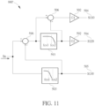
- FIG. 9 is a schematic diagram of a 3-way SPD 90 according to an embodiment of the present application.
- FIG. 9a illustrates the structure of the SPD 90.
- FIG. 9b illustrates the frequency response corresponding to a crossover circuit 990 of the SPD 90.
- a sound generating/producing cell array 900A of the SPD 90 may include the cells 110, 130 and 120 of different types.
- FIG. 10 is a schematic diagram illustrating a top view of a sound generating/producing cell array 900B.
- the cell array 900A shown in FIG. 9 may be implemented as the cell array 900B
- the cell array 900B includes two tweeter cells 110 covering the frequency band corresponding to MR1 and producing sound/pressure P110, one woofer cell 130 covering the frequency band corresponding to MR3 and producing sound/pressure P130, and one mid-range cell 120 covering the frequency band corresponding to MR2 and producing sound/pressure P120.
- the cell 120 may function as a midrange driver to cover midrange frequency.
- the area of the membrane 120M (within the mid-range cell 120) is larger than that of the membrane 110M (within the tweeter cell 110) and smaller than that of the membrane 130M (within the woofer cell 110), while the resonance frequency of the (mid-range) membrane 120M may be lower than that of the (tweeter) membrane 110M and higher than that of the (woofer) membrane 130M.
- the resonance frequency of the (mid-range) cell 120 may be significantly higher than a crossover frequency fcx2 between the driving signal S120 and driving signal S110 (which would be elaborated later).
- a crossover frequency fcx1 between audio bands corresponding to MR3 and MR2, may be in a range of 300Hz ⁇ 1KHz, while the crossover frequency fcx2, between audio bands corresponding to MR1 and MR2 may be in a range of 2KHz to 6KHz.
- the cells 110, 120, 130 may be made of a Silicon-On-Insulator (SOI) or Poly-On-Insulator (POI) wafer; a Si layer or Poly layer forms the membranes 110M, 120M, 130M; a Si substrate of the SOI or POI wafer forms a cell-to-cell partition wall 102 and an overall chip border wall 106.
- the cells 110, 120, 130 may be fabricated out of a monolithic silicon substrate and may be integrally formed, such that the cells 110, 120, 130 are formed with the same material and their connection has no mechanical joints.
- the crossover circuit 990 shown in FIG. 9 is configured to partition the input signal Sn into three driving signals S110, S120, S130 and transmitted toward the cells 110, 120, 130, respectively.
- the crossover circuit 990 may be required to perform a low-pass filtering operation, a band-pass filtering operation and a high-pass filtering operation, to generate the driving signal S130, S120 and S110, respectively, according to the input signal Sn.
- the crossover circuit 990 may include the HPF 501 (to perform the high-pass filtering operation), the LPF 503 (to perform the low-pass filtering operation), and a band-pass filter for the cell 120.
- the function of the band-pass filtering operation is performed by taking the output signal from LPF 503, connecting it to the negative input terminal of the subtractor 596 to subtract it (i.e., the output signal of LPF 503) from the input signal of LPF 503, i.e., Sn, and performing low-pass filtering operation on the resulting signal (produced by the subtractor 596) by an LPF 593.
- the function of HPF 501 (or high-pass filtering operation) is performed by taking the output signal from the LPF 593, connecting it to the negative input terminal of the subtractor 506 to subtract it from the input signal of LPF 593.
- the input signal Sn may be in pulse-code modulation (PCM) format at 48Ksps (kilo samples per second) or 96Ksps sample rate.
- PCM pulse-code modulation
- the resonance frequency of a membrane may be lowered while the maximum input frequency (namely, the maximum frequency of the driving signal S120 or S130) is significantly lower than the resonance frequency of the membrane as disclosed in U.S. provisional application No. 62/897,365 and/or U.S. Patent No. 10,805,751 .
- the present invention may have lower membrane stiffness, increased membrane compliance, more effective membrane design, improved unit silicon area sound generating efficacy of the cells (e.g., the cells 120 and 130) without sacrificing the quality of the sound or the consistency of production following the design principle disclosed in U.S. provisional application No. 62/897,365 and/or U.S. Patent No. 10,805,751 .
- the membrane leakage through slit(s) constituting a membrane pattern may be mitigated for a cell (e.g., the cell 110) not responsible for producing lower registers of sound. Therefore, more efficient membrane design may be applied, resulting in improved unit silicon area sound generating efficacy of the cells (e.g., the cells 120 and 130).
Landscapes
- Engineering & Computer Science (AREA)
- Physics & Mathematics (AREA)
- Acoustics & Sound (AREA)
- Signal Processing (AREA)
- Health & Medical Sciences (AREA)
- Multimedia (AREA)
- Otolaryngology (AREA)
- General Health & Medical Sciences (AREA)
- Manufacturing & Machinery (AREA)
- Chemical & Material Sciences (AREA)
- Analytical Chemistry (AREA)
- Computer Hardware Design (AREA)
- Microelectronics & Electronic Packaging (AREA)
- Audiology, Speech & Language Pathology (AREA)
- Circuit For Audible Band Transducer (AREA)
- Piezo-Electric Transducers For Audible Bands (AREA)
Claims (15)
- Schallerzeugungsgerät (10, 90), abgekürzt als SPD, welches umfasst:
eine erste Tonerzeugungszelle (110) mit einer ersten Membran (110M), die durch ein erstes Ansteuersignal (S110) angesteuert wird und ausgestaltet ist, einen ersten akustischen Ton (P110) auf einem ersten Audioband zu erzeugen, wobei ein erstes Membranmuster (310, 610P1) der ersten Tonerzeugungszelle umfasst:mindestens ein Schlitzsegment (312, 413), das entlang mindestens einer äußersten Kante der ersten Tonerzeugungszelle (110) angeordnet ist; odermehrere Membranunterteile (310A-310D, 411-412), die voneinander getrennt sind; undeine zweite Tonerzeugungszelle (130), die eine zweite Membran (130M) umfasst, die durch ein zweites Ansteuersignal (S130) angesteuert wird und ausgestaltet ist, einen zweiten akustischen Ton (P130) auf einem zweiten Tonband zu erzeugen, das sich von dem ersten Audioband unterscheidet;worin die erste Membran und die zweite Membran durch ein mikroelektromechanisches System, abgekürzt MEMS, hergestellte Membranen sind;wobei das erste Audioband, das dem ersten Ansteuersignal (S110) entspricht, durch eine erste Maximalfrequenz (fmax, S110) nach oben begrenzt ist, und das zweite Audioband, das dem zweiten Ansteuersignal (S130) entspricht, durch eine zweite Maximalfrequenz nach oben begrenzt ist;dadurch gekennzeichnet, dass:eine erste Resonanzfrequenz (fr, 110) der ersten Membran (110M) höher ist als die erste maximale Frequenz (fmax, S110) des ersten Ansteuersignals (S110);wobei eine zweite Resonanzfrequenz (fr, 130) der zweiten Membran (130M) höher ist als die zweite Maximalfrequenz des zweiten Ansteuersignals (S130);worin ein erstes Membranmuster der ersten Tonerzeugungszelle umfasst: mindestens ein Schlitzsegment, das entlang mindestens einer äußersten Kante der ersten Tonerzeugungszelle angeordnet ist; oder mehrere voneinander getrennte Membranunterteile. - SPD nach Anspruch 1, welches umfasst:eine Frequenzweiche (190, 290, 890A, 890B, 990, 990'), die mit der ersten Membran und der zweiten Membran gekoppelt und ausgestaltet ist, das erste Ansteuersignal (S110) und das zweite Ansteuersignal (S130) zu erzeugen, worin die Frequenzweiche eine Übergangsfrequenz (fcx) aufweist;wobei die erste Resonanzfrequenz (fr, 110) höher ist als die zweite Resonanzfrequenz (fr, 130), und die zweite Resonanzfrequenz (fr, 130) höher ist als die Übergangsfrequenz (fcx).
- SPD nach einem der Ansprüche 1-2, wobei die erste Maximalfrequenz (fmax, S110) höher ist als die zweite Resonanzfrequenz (fr, 130).
- Das SPD nach einem der Ansprüche 1-3,worin sich ein erster Bereich der ersten Membran (110M) von einem zweiten Bereich der zweiten Membran (130M) unterscheidet, so dass die erste Resonanzfrequenz (fr, 110) höher ist als die zweite Resonanzfrequenz (fr, 130);worin sich das erste Membranmuster (310, 610P1) der ersten Tonerzeugungszelle (110) von einem zweiten Membranmuster (330) der zweiten Tonerzeugungszelle (130) unterscheidet, so dass die erste Resonanzfrequenz (fr, 110) höher ist als die zweite Resonanzfrequenz (fr, 130);worin das erste Membranmuster (310, 610P1) der ersten Tonerzeugungszelle (110) andere Freiheitsgrade aufweist als ein zweites Membranmuster (330) der zweiten Tonerzeugungszelle (130), so dass die erste Resonanzfrequenz (fr,110) höher ist als die zweite Resonanzfrequenz (fr,130); oderwobei eine erste Membransteifigkeit der ersten Tonerzeugungszelle (110) sich von einer zweiten Membransteifigkeit der zweiten Tonerzeugungszelle (130) unterscheidet, so dass die erste Resonanzfrequenz (fr,110) höher ist als die zweite Resonanzfrequenz (fr,130).
- SPD nach einem der Ansprüche 1-4, welches eine Frequenzweiche (190, 290, 890A, 890B, 990) umfasst, die mit der ersten Membran und der zweiten Membran gekoppelt ist und ausgestaltet ist, das erste Ansteuersignal und das zweite Ansteuersignal zu erzeugen, worin die Frequenzweiche (290, 890A, 890B) umfasst:
einen ersten Filter (503, 501), wobei die Frequenzweichenschaltung ein Ansteuersignal des ersten und zweiten Ansteuersignals entsprechend einem ersten Ausgangssignal des ersten Filters erzeugt. - SPD nach Anspruch 5, wobei die Frequenzweiche umfasst:einen zweiten Filter (501), wobei die Frequenzweichenschaltung ein anderes Ansteuersignal der ersten und zweiten Ansteuersignale als das eine Ansteuersignal, das gemäß dem ersten Ausgangssignal erzeugt wird, entsprechend einem zweiten Ausgangssignal des zweiten Filters erzeugt;eine Verstärkungsschaltung (502), worin die Verstärkungsschaltung mit der ersten Tonerzeugungszelle gekoppelt und ausgestaltet ist, einen Empfindlichkeitsunterschied zwischen der ersten Tonerzeugungszelle und der zweiten Tonerzeugungszelle zu kompensieren; odereine Subtraktionsschaltung (506), worin ein Eingangsanschluss des ersten Filters mit einem ersten Eingangsanschluss der Subtraktionsschaltung gekoppelt ist, ein Ausgangsanschluss des ersten Filters mit einem zweiten Eingangsanschluss der Subtraktionsschaltung gekoppelt ist, wobei die Frequenzweichenschaltung entsprechend einem zweiten Ausgangssignal der Subtraktionsschaltung (506) ein anderes Ansteuersignal der ersten und zweiten Ansteuersignale als das eine Ansteuersignal erzeugt, das gemäß dem ersten Ausgangssignal erzeugt wird.
- SPD nach Anspruch 5, worin der erste Filter Speichereinheiten und Addierer zur Durchführung von Filterkoeffizientenmultiplikationen umfasst und die ersten Filter keine Multiplikationsschaltung enthalten.
- SPD nach einem der Ansprüche 1-7, welches ferner umfasst:eine dritte Tonerzeugungszelle, die eine dritte Membran (120M) umfasst, die mit einer Frequenzweichenschaltung (990) gekoppelt ist und durch ein drittes Ansteuersignal (S120) angesteuert wird, das von der Frequenzweichenschaltung (990) erzeugt wird, und die ausgestaltet ist, einen dritten akustischen Ton (P120) in einem dritten Audioband zu erzeugen, das sich von dem ersten Audioband und dem zweiten Audioband unterscheidet;wobei das dritte Audioband, das dem dritten Ansteuersignal (S120) entspricht, durch eine dritte Maximalfrequenz (fmax, S120) nach oben begrenzt ist;wobei eine dritte Resonanzfrequenz (fr, 120) der dritten Membran (120M) höher ist als die dritte Maximalfrequenz (fmax, S120).
- SPD nach Anspruch 8, wobei die dritte Resonanzfrequenz (fr, 120) höher ist als die zweite Resonanzfrequenz (fr, 130) und niedriger als die erste Resonanzfrequenz (fr, 110).
- SPD nach einem der Ansprüche 1-9, welches eine Frequenzweiche (190, 290, 890A, 890B, 990, 990') umfasst, die ausgestaltet ist, das erste Ansteuersignal für die erste Tonerzeugungszelle und das zweite Ansteuersignal für die zweite Tonerzeugungszelle zu erzeugen, worin die Frequenzweiche ein Linkwitz-Riley-Filter umfasst.
- SPD nach einem der Ansprüche 1-10, wobei eine erste maximale SPL-Anforderung der ersten Tonerzeugungszelle (110) niedriger ist als eine zweite maximale SPL-Anforderung der zweiten Tonerzeugungszelle (130), wenn das SPD (10) als In-Ear-Monitor-Lautsprecher funktioniert.
- SPD nach einem der Ansprüche 1-11, wobeiein von dem SPD erzeugter aggregierter Ton (P110+P130) den ersten akustischen Ton (P110) und den zweiten akustischen Ton (P130) umfasst;das SPD den Gesamtschall entsprechend einem Eingangssignal (Sn) erzeugt;eine Phasenverschiebung des aggregierten Schalls in Bezug auf das Eingangssignal (Sn) weniger als 25° beträgt.
- SPD nach einem der Ansprüche 1-12, wobeiein Summensignal (S110+S130) durch eine Summierung des ersten Ansteuersignals (S110) und des zweiten Ansteuersignals (S 130) gebildet wird;der SPD das erste Ansteuersignal (S110) und das zweite Ansteuersignal (S 130) entsprechend einem Eingangssignal (Sn) erzeugt;eine Phasenverschiebung des Summensignals (S110+S130) in Bezug auf das Eingangssignal (Sn) weniger als 20° beträgt.
- SPD nach einem der Ansprüche 1-13, worin das SPD in einem tragbaren Hörgerät mit oder ohne aktive Geräuschunterdrückungsfunktion angeordnet ist.
- SPD nach einem der Ansprüche 1-14, worindie mehreren Membranunterteile (310A-310D, 411-412) ein erstes Membranunterteil (411) und ein zweites Membranunterteil (412) umfassen;worin nur eine Kante (414) sowohl des ersten Membranunterteils (411) als auch des zweiten Membranunterteils (412) verankert ist und andere Kanten sowohl des ersten Membranunterteils (411) als auch des zweiten Membranunterteils (412) freigegeben sind.
Applications Claiming Priority (4)
| Application Number | Priority Date | Filing Date | Title |
|---|---|---|---|
| US202062971364P | 2020-02-07 | 2020-02-07 | |
| US202063105286P | 2020-10-24 | 2020-10-24 | |
| US202063112860P | 2020-11-12 | 2020-11-12 | |
| US17/153,849 US11172300B2 (en) | 2020-02-07 | 2021-01-20 | Sound producing device |
Publications (3)
| Publication Number | Publication Date |
|---|---|
| EP3886459A1 EP3886459A1 (de) | 2021-09-29 |
| EP3886459C0 EP3886459C0 (de) | 2023-12-13 |
| EP3886459B1 true EP3886459B1 (de) | 2023-12-13 |
Family
ID=77176875
Family Applications (1)
| Application Number | Title | Priority Date | Filing Date |
|---|---|---|---|
| EP21154023.2A Active EP3886459B1 (de) | 2020-02-07 | 2021-01-28 | Schallerzeugungsvorrichtung, frequenzweiche und schallerzeugungszelle dafür |
Country Status (2)
| Country | Link |
|---|---|
| US (1) | US11172300B2 (de) |
| EP (1) | EP3886459B1 (de) |
Families Citing this family (4)
| Publication number | Priority date | Publication date | Assignee | Title |
|---|---|---|---|---|
| EP4294050A1 (de) * | 2022-06-17 | 2023-12-20 | Infineon Technologies AG | Mems-verpackung und audiovorrichtung, die eine solche mems-verpackung umfasst |
| US11991497B1 (en) * | 2022-10-28 | 2024-05-21 | xMEMS Labs, Inc. | Acoustic device and holder flattening frequency response |
| SE2350768A1 (en) | 2023-06-22 | 2024-12-23 | Myvox Ab | A sound producing device, a sound producing system and a method of manufacturing a sound producing device |
| DE102023208731A1 (de) * | 2023-09-08 | 2025-03-13 | Robert Bosch Gesellschaft mit beschränkter Haftung | Verfahren zum Betrieb einer mikroelektromechanischen Vorrichtung, mikroelektromechanische Vorrichtung, mikroelektromechanischer Lautsprecher, mikroelektromechanische Fluidpumpeinrichtung und mikroelektromechanisches Kombinationsbauelement |
Family Cites Families (12)
| Publication number | Priority date | Publication date | Assignee | Title |
|---|---|---|---|---|
| JP3644259B2 (ja) | 1998-03-24 | 2005-04-27 | 株式会社村田製作所 | スピーカ装置 |
| JP2009044600A (ja) | 2007-08-10 | 2009-02-26 | Panasonic Corp | マイクロホン装置およびその製造方法 |
| KR20120056020A (ko) | 2010-11-24 | 2012-06-01 | 삼성전자주식회사 | 마이크로 음향 변환기 |
| WO2013061204A2 (en) * | 2011-10-28 | 2013-05-02 | Koninklijke Philips Electronics N.V. | Pre-collapsed capacitive micro-machined transducer cell with plug |
| US9774959B2 (en) * | 2015-03-25 | 2017-09-26 | Dsp Group Ltd. | Pico-speaker acoustic modulator |
| US9843862B2 (en) * | 2015-08-05 | 2017-12-12 | Infineon Technologies Ag | System and method for a pumping speaker |
| WO2017068711A1 (ja) | 2015-10-23 | 2017-04-27 | 株式会社日立製作所 | Mems装置 |
| US10367430B2 (en) * | 2016-01-11 | 2019-07-30 | Infineon Technologies Ag | System and method for a variable flow transducer |
| WO2018195230A1 (en) | 2017-04-18 | 2018-10-25 | Massachusetts Institute Of Technology | Electrostatic acoustic transducer |
| GB2576687B (en) * | 2018-02-01 | 2022-04-13 | 8Power Ltd | Vibrational energy harvester with piston damping |
| US11418887B2 (en) * | 2019-08-28 | 2022-08-16 | Taiwan Semiconductor Manufacturing Company Ltd. | MEMS device with enhanced membrane structure and method of forming the same |
| US10805751B1 (en) | 2019-09-08 | 2020-10-13 | xMEMS Labs, Inc. | Sound producing device |
-
2021
- 2021-01-20 US US17/153,849 patent/US11172300B2/en active Active
- 2021-01-28 EP EP21154023.2A patent/EP3886459B1/de active Active
Also Published As
| Publication number | Publication date |
|---|---|
| EP3886459C0 (de) | 2023-12-13 |
| EP3886459A1 (de) | 2021-09-29 |
| US20210250689A1 (en) | 2021-08-12 |
| US11172300B2 (en) | 2021-11-09 |
Similar Documents
| Publication | Publication Date | Title |
|---|---|---|
| EP3886459B1 (de) | Schallerzeugungsvorrichtung, frequenzweiche und schallerzeugungszelle dafür | |
| KR102465792B1 (ko) | 사운드 생성 디바이스 | |
| JP2022016392A (ja) | 音響トランスデューサ、ウェアラブルサウンドデバイス及び音響トランスデューサの製造方法 | |
| JP2022016393A (ja) | 音響トランスデューサ、ウェアラブルサウンドデバイス及び音響トランスデューサの製造方法 | |
| CN111742562B (zh) | 具有校正电路系统的方向性微机电系统麦克风 | |
| CN101453684A (zh) | 声音输入装置 | |
| KR20120014591A (ko) | 감소된 진동 감도를 갖는 마이크로폰 | |
| CN1130459A (zh) | 用于助听器的听音器 | |
| WO2000070630A3 (en) | High performance mems thin-film teflon® electret microphone | |
| CN217693709U (zh) | Mems扬声器 | |
| JPWO2006062120A1 (ja) | マイクロホン装置 | |
| KR20120056020A (ko) | 마이크로 음향 변환기 | |
| KR100736894B1 (ko) | 다채널 진동판이 구비된 전기-음향 변환장치 및 이를이용한 보청기 | |
| JP3896967B2 (ja) | 圧電スピーカ | |
| KR102475665B1 (ko) | 크로스오버 회로 | |
| JP5175612B2 (ja) | フレキシブルステレオスピーカ | |
| CN110337056B (zh) | 一种高密度指向性压电电声换能器阵列的制作方法 | |
| US11304005B2 (en) | Crossover circuit | |
| Fankhänel et al. | Highly miniaturized MEMS speakers for in-ear applications | |
| TWI609367B (zh) | 電子裝置及利用窗化濾波器差異之特定頻段補償增益方法 | |
| CN113286216B (zh) | 音频系统和音频方法 | |
| EP1051058A2 (de) | Piezoelektrisches Audiogerät und Verfahren zur Schallwiedergabe | |
| CN115706905A (zh) | 一种压电mems扬声器 | |
| EP0188609A1 (de) | Piezoelektrischer lautsprecher mit feedback-umwandler | |
| JP2002291099A (ja) | スピーカシステム |
Legal Events
| Date | Code | Title | Description |
|---|---|---|---|
| PUAI | Public reference made under article 153(3) epc to a published international application that has entered the european phase |
Free format text: ORIGINAL CODE: 0009012 |
|
| STAA | Information on the status of an ep patent application or granted ep patent |
Free format text: STATUS: THE APPLICATION HAS BEEN PUBLISHED |
|
| STAA | Information on the status of an ep patent application or granted ep patent |
Free format text: STATUS: REQUEST FOR EXAMINATION WAS MADE |
|
| AK | Designated contracting states |
Kind code of ref document: A1 Designated state(s): AL AT BE BG CH CY CZ DE DK EE ES FI FR GB GR HR HU IE IS IT LI LT LU LV MC MK MT NL NO PL PT RO RS SE SI SK SM TR |
|
| 17P | Request for examination filed |
Effective date: 20210909 |
|
| RBV | Designated contracting states (corrected) |
Designated state(s): AL AT BE BG CH CY CZ DE DK EE ES FI FR GB GR HR HU IE IS IT LI LT LU LV MC MK MT NL NO PL PT RO RS SE SI SK SM TR |
|
| STAA | Information on the status of an ep patent application or granted ep patent |
Free format text: STATUS: EXAMINATION IS IN PROGRESS |
|
| 17Q | First examination report despatched |
Effective date: 20220216 |
|
| GRAP | Despatch of communication of intention to grant a patent |
Free format text: ORIGINAL CODE: EPIDOSNIGR1 |
|
| STAA | Information on the status of an ep patent application or granted ep patent |
Free format text: STATUS: GRANT OF PATENT IS INTENDED |
|
| INTG | Intention to grant announced |
Effective date: 20230905 |
|
| GRAS | Grant fee paid |
Free format text: ORIGINAL CODE: EPIDOSNIGR3 |
|
| GRAA | (expected) grant |
Free format text: ORIGINAL CODE: 0009210 |
|
| STAA | Information on the status of an ep patent application or granted ep patent |
Free format text: STATUS: THE PATENT HAS BEEN GRANTED |
|
| AK | Designated contracting states |
Kind code of ref document: B1 Designated state(s): AL AT BE BG CH CY CZ DE DK EE ES FI FR GB GR HR HU IE IS IT LI LT LU LV MC MK MT NL NO PL PT RO RS SE SI SK SM TR |
|
| REG | Reference to a national code |
Ref country code: GB Ref legal event code: FG4D |
|
| REG | Reference to a national code |
Ref country code: CH Ref legal event code: EP |
|
| REG | Reference to a national code |
Ref country code: DE Ref legal event code: R096 Ref document number: 602021007554 Country of ref document: DE |
|
| REG | Reference to a national code |
Ref country code: IE Ref legal event code: FG4D |
|
| U01 | Request for unitary effect filed |
Effective date: 20240105 |
|
| U07 | Unitary effect registered |
Designated state(s): AT BE BG DE DK EE FI FR IT LT LU LV MT NL PT SE SI Effective date: 20240116 |
|
| U20 | Renewal fee for the european patent with unitary effect paid |
Year of fee payment: 4 Effective date: 20240125 |
|
| PG25 | Lapsed in a contracting state [announced via postgrant information from national office to epo] |
Ref country code: GR Free format text: LAPSE BECAUSE OF FAILURE TO SUBMIT A TRANSLATION OF THE DESCRIPTION OR TO PAY THE FEE WITHIN THE PRESCRIBED TIME-LIMIT Effective date: 20240314 |
|
| PG25 | Lapsed in a contracting state [announced via postgrant information from national office to epo] |
Ref country code: ES Free format text: LAPSE BECAUSE OF FAILURE TO SUBMIT A TRANSLATION OF THE DESCRIPTION OR TO PAY THE FEE WITHIN THE PRESCRIBED TIME-LIMIT Effective date: 20231213 |
|
| PG25 | Lapsed in a contracting state [announced via postgrant information from national office to epo] |
Ref country code: GR Free format text: LAPSE BECAUSE OF FAILURE TO SUBMIT A TRANSLATION OF THE DESCRIPTION OR TO PAY THE FEE WITHIN THE PRESCRIBED TIME-LIMIT Effective date: 20240314 Ref country code: ES Free format text: LAPSE BECAUSE OF FAILURE TO SUBMIT A TRANSLATION OF THE DESCRIPTION OR TO PAY THE FEE WITHIN THE PRESCRIBED TIME-LIMIT Effective date: 20231213 |
|
| PG25 | Lapsed in a contracting state [announced via postgrant information from national office to epo] |
Ref country code: RS Free format text: LAPSE BECAUSE OF FAILURE TO SUBMIT A TRANSLATION OF THE DESCRIPTION OR TO PAY THE FEE WITHIN THE PRESCRIBED TIME-LIMIT Effective date: 20231213 Ref country code: NO Free format text: LAPSE BECAUSE OF FAILURE TO SUBMIT A TRANSLATION OF THE DESCRIPTION OR TO PAY THE FEE WITHIN THE PRESCRIBED TIME-LIMIT Effective date: 20240313 Ref country code: HR Free format text: LAPSE BECAUSE OF FAILURE TO SUBMIT A TRANSLATION OF THE DESCRIPTION OR TO PAY THE FEE WITHIN THE PRESCRIBED TIME-LIMIT Effective date: 20231213 |
|
| PG25 | Lapsed in a contracting state [announced via postgrant information from national office to epo] |
Ref country code: IS Free format text: LAPSE BECAUSE OF FAILURE TO SUBMIT A TRANSLATION OF THE DESCRIPTION OR TO PAY THE FEE WITHIN THE PRESCRIBED TIME-LIMIT Effective date: 20240413 |
|
| PG25 | Lapsed in a contracting state [announced via postgrant information from national office to epo] |
Ref country code: CZ Free format text: LAPSE BECAUSE OF FAILURE TO SUBMIT A TRANSLATION OF THE DESCRIPTION OR TO PAY THE FEE WITHIN THE PRESCRIBED TIME-LIMIT Effective date: 20231213 |
|
| PG25 | Lapsed in a contracting state [announced via postgrant information from national office to epo] |
Ref country code: SK Free format text: LAPSE BECAUSE OF FAILURE TO SUBMIT A TRANSLATION OF THE DESCRIPTION OR TO PAY THE FEE WITHIN THE PRESCRIBED TIME-LIMIT Effective date: 20231213 |
|
| PG25 | Lapsed in a contracting state [announced via postgrant information from national office to epo] |
Ref country code: SM Free format text: LAPSE BECAUSE OF FAILURE TO SUBMIT A TRANSLATION OF THE DESCRIPTION OR TO PAY THE FEE WITHIN THE PRESCRIBED TIME-LIMIT Effective date: 20231213 Ref country code: SK Free format text: LAPSE BECAUSE OF FAILURE TO SUBMIT A TRANSLATION OF THE DESCRIPTION OR TO PAY THE FEE WITHIN THE PRESCRIBED TIME-LIMIT Effective date: 20231213 Ref country code: RO Free format text: LAPSE BECAUSE OF FAILURE TO SUBMIT A TRANSLATION OF THE DESCRIPTION OR TO PAY THE FEE WITHIN THE PRESCRIBED TIME-LIMIT Effective date: 20231213 Ref country code: IS Free format text: LAPSE BECAUSE OF FAILURE TO SUBMIT A TRANSLATION OF THE DESCRIPTION OR TO PAY THE FEE WITHIN THE PRESCRIBED TIME-LIMIT Effective date: 20240413 Ref country code: CZ Free format text: LAPSE BECAUSE OF FAILURE TO SUBMIT A TRANSLATION OF THE DESCRIPTION OR TO PAY THE FEE WITHIN THE PRESCRIBED TIME-LIMIT Effective date: 20231213 |
|
| PG25 | Lapsed in a contracting state [announced via postgrant information from national office to epo] |
Ref country code: PL Free format text: LAPSE BECAUSE OF FAILURE TO SUBMIT A TRANSLATION OF THE DESCRIPTION OR TO PAY THE FEE WITHIN THE PRESCRIBED TIME-LIMIT Effective date: 20231213 |
|
| PG25 | Lapsed in a contracting state [announced via postgrant information from national office to epo] |
Ref country code: PL Free format text: LAPSE BECAUSE OF FAILURE TO SUBMIT A TRANSLATION OF THE DESCRIPTION OR TO PAY THE FEE WITHIN THE PRESCRIBED TIME-LIMIT Effective date: 20231213 |
|
| REG | Reference to a national code |
Ref country code: CH Ref legal event code: PL |
|
| REG | Reference to a national code |
Ref country code: DE Ref legal event code: R097 Ref document number: 602021007554 Country of ref document: DE |
|
| PG25 | Lapsed in a contracting state [announced via postgrant information from national office to epo] |
Ref country code: MC Free format text: LAPSE BECAUSE OF FAILURE TO SUBMIT A TRANSLATION OF THE DESCRIPTION OR TO PAY THE FEE WITHIN THE PRESCRIBED TIME-LIMIT Effective date: 20231213 |
|
| PLBE | No opposition filed within time limit |
Free format text: ORIGINAL CODE: 0009261 |
|
| STAA | Information on the status of an ep patent application or granted ep patent |
Free format text: STATUS: NO OPPOSITION FILED WITHIN TIME LIMIT |
|
| PG25 | Lapsed in a contracting state [announced via postgrant information from national office to epo] |
Ref country code: CH Free format text: LAPSE BECAUSE OF NON-PAYMENT OF DUE FEES Effective date: 20240131 |
|
| PG25 | Lapsed in a contracting state [announced via postgrant information from national office to epo] |
Ref country code: CH Free format text: LAPSE BECAUSE OF NON-PAYMENT OF DUE FEES Effective date: 20240131 |
|
| 26N | No opposition filed |
Effective date: 20240916 |
|
| U20 | Renewal fee for the european patent with unitary effect paid |
Year of fee payment: 5 Effective date: 20241104 |
|
| PG25 | Lapsed in a contracting state [announced via postgrant information from national office to epo] |
Ref country code: IE Free format text: LAPSE BECAUSE OF NON-PAYMENT OF DUE FEES Effective date: 20240128 |
|
| PG25 | Lapsed in a contracting state [announced via postgrant information from national office to epo] |
Ref country code: IE Free format text: LAPSE BECAUSE OF NON-PAYMENT OF DUE FEES Effective date: 20240128 |
|
| PG25 | Lapsed in a contracting state [announced via postgrant information from national office to epo] |
Ref country code: CY Free format text: LAPSE BECAUSE OF FAILURE TO SUBMIT A TRANSLATION OF THE DESCRIPTION OR TO PAY THE FEE WITHIN THE PRESCRIBED TIME-LIMIT; INVALID AB INITIO Effective date: 20210128 |
|
| PG25 | Lapsed in a contracting state [announced via postgrant information from national office to epo] |
Ref country code: HU Free format text: LAPSE BECAUSE OF FAILURE TO SUBMIT A TRANSLATION OF THE DESCRIPTION OR TO PAY THE FEE WITHIN THE PRESCRIBED TIME-LIMIT; INVALID AB INITIO Effective date: 20210128 |
|
| GBPC | Gb: european patent ceased through non-payment of renewal fee |
Effective date: 20250128 |
|
| PG25 | Lapsed in a contracting state [announced via postgrant information from national office to epo] |
Ref country code: GB Free format text: LAPSE BECAUSE OF NON-PAYMENT OF DUE FEES Effective date: 20250128 |
|
| PG25 | Lapsed in a contracting state [announced via postgrant information from national office to epo] |
Ref country code: TR Free format text: LAPSE BECAUSE OF FAILURE TO SUBMIT A TRANSLATION OF THE DESCRIPTION OR TO PAY THE FEE WITHIN THE PRESCRIBED TIME-LIMIT Effective date: 20231213 |
|
| U20 | Renewal fee for the european patent with unitary effect paid |
Year of fee payment: 6 Effective date: 20251205 |