-
Die Erfindung betrifft eine Steckverbinderbaugruppe mit einer Leiterführungseinrichtung und einem Hebel. Die Erfindung betrifft weiterhin ein Stecksystem mit einer Steckverbinderbaugruppe und einem Steckplatz sowie ein Verfahren zum Verriegeln und Verbinden einer Steckverbinderbaugruppe an einem Steckplatz.
-
Elektrische Steckverbinder können als eine verriegelbare Steckverbinderbaugruppe ausgebildet sein, insbesondere als eine CPA-Steckverbinderbaugruppe, und mehrere Elemente und/oder Module aufweisen. Dabei kann die Steckverbinderbaugruppe z.B. eine Leiterführungseinrichtung aufweisen als ein Hauptmodul und/oder Hauptelement und/oder Hauptbauteil. Die Leiterführungseinrichtung führt in ihrem Inneren elektrische Leiter und/oder elektrische Kontakte. Die Steckverbinderbaugruppe weist zumindest einen Hebel als ein zweites Modul und/oder Element und/oder Bauteil auf, mit welchem die Leiterführungseinrichtung in einer Steckverbindung mit einem Steckplatz verriegelt werden kann. Die Verriegelung ist als Schutz vor einem unbeabsichtigten Lösen der Steckverbindung konfiguriert. Als ein drittes Element und/oder Modul und/oder Bauteil kann die Steckverbinderbaugruppe weiterhin eine CPA-Einrichtung aufweisen. Dabei steht "CPA" als eine Abkürzung für das englische "connector position assurance". Die CPA-Einrichtung kann benutzt werden, um den Hebel in der verriegelten Position zu sichern. Dadurch wird verhindert, dass sich der Hebel von seiner Verriegelungsposition in eine Entriegelungsposition bewegt, wodurch die Leiterführungseinrichtung und somit die Steckverbinderbaugruppe entriegelt wird und sich lösen kann vom Steckplatz.
-
Derartig verriegelbare Steckverbinderbaugruppen werden insbesondere im Automotive-Bereich genutzt, z.B. als ABS-Steckverbinder, also als Antiblockiersystemsteckverbinder.
-
Aus dem Stand der Technik sind CPA-Steckverbinderbaugruppen bekannt, bei denen ein dem Steckplatz zugewandtes Hebelende in der Verriegelungsposition einen Vorsprung des Steckplatzes derart umgreift, dass eine formschlüssige Verbindung zwischen der Steckverbinderbaugruppe und dem Steckplatz bereitgestellt wird.
-
Der Erfindung liegt die Aufgabe zugrunde, eine verriegelbare Steckverbinderbaugruppe bereitzustellen, die möglichst einfach und/oder sicher am Steckplatz verriegelbar ist.
-
Diese Aufgabe wird durch die Gegenstände der unabhängigen Ansprüche gelöst. Bevorzugte Ausführungsformen sind die Gegenstände der abhängigen Ansprüche.
-
Ein Aspekt betrifft eine Steckverbinderbaugruppe mit einer Leiterführungseinrichtung, welche dazu konfiguriert ist, eine Steckverbindung mit einem Steckplatz derart einzugehen, dass in der Leiterführungseinrichtung geführte elektrische Leiter elektrische Kontakte des Steckplatzes kontaktieren. Ein Hebel der Steckverbinderbaugruppe ist an der Steckverbinderbaugruppe angeordnet und zwischen einer Verriegelungsposition, in welcher der Hebel die Leiterführungseinrichtung in der Steckverbindung mit dem Steckplatz verriegelt, und einer Entriegelposition, in welcher die Leiterführungseinrichtung vom Steckplatz lösbar ist, beweglich. Ein Schieber ist an der Steckverbinderbaugruppe angeordnet und zwischen einer Verbindungsposition, in welcher der Schieber eine formund/oder kraftschlüssigen Verbindung zwischen der Leiterführungseinrichtung und dem Steckplatz bereitstellt und/oder eingeht, und einer Entnahmeposition, in welcher die Steckverbinderbaugruppe vom Steckplatz entnehmbar ist, beweglich. Dabei ist der Hebel so mit dem Schieber gekoppelt, dass der Hebel beim Bewegen von der Entriegelposition in die Verriegelungsposition den Schieber von der Entnahmeposition in die Verbindungsposition bewegt.
-
Die Steckverbinderbaugruppe kann als eine CPA-Steckverbinderbaugruppe der eingangs genannten Art und/oder als ein mehrpoliger Steckverbinder ausgebildet sein, insbesondere als eine mehrpolige Steckverbinderbaugruppe für den Automotive-Bereich. Die Steckverbinderbaugruppe kann insbesondere als eine ABS-Steckverbinderbaugruppe ausgebildet sein, also eine Steckverbinderbaugruppe für das Antiblockiersystem eines Kraftfahrzeugs. Die Steckverbinderbaugruppe ist zumindest dreiteilig aufgebaut, wobei die Leiterführungseinrichtung als Basisbauteil und/oder Hauptbauteil der Steckverbinderbaugruppe ausgebildet ist, an welcher zumindest der Hebel als zweites Bauteil befestigt und angeordnet ist. Der Schieber ist als ein drittes Bauteil der Steckverbinderbaugruppe ausgebildet und kann z.B. ebenfalls an der Leiterführungseinrichtung befestigt sein. Die Steckverbinderbaugruppe kann weiterhin eine CPA-Einrichtung als ein viertes Bauteil aufweisen, und/oder eine Schieberführung als ein weiteres Bauteil.
-
Im Inneren der Leiterführungseinrichtung ist eine Mehrzahl elektrischer Leiter geführt, welche im Inneren der Leiterführungseinrichtung hin zu einer Steck- und/oder Verbindungsseite der Leiterführungseinrichtung geführt sind. An dieser Steckund/oder Verbindungsseite der Leiterführungseinrichtung ist die Leiterführungseinrichtung dazu ausgebildet, so auf den Steckplatz gesteckt zu werden, dass die im Inneren geführten elektrischen Leiter elektrische Kontakte des Steckplatzes elektrisch und/oder mechanisch kontaktieren. Der Steckplatz kann zum Beispiel als eine Buchse und/oder komplementärer Steckverbinder ausgebildet sein und/oder eine Platine aufweisen, mit der die Steckverbinderbaugruppe elektrisch verbindbar ist. Dabei kann die Leiterführungseinrichtung mit ihrer Steckseite entweder unmittelbar auf Steckplatz gesteckt werden oder mittelbar über ein weiteres Bauteil der Steckverbinderbaugruppe, wie etwa die ggf. vorhandene Schieberführung.
-
Der Hebel ist an der Steckverbinderbaugruppe, z.B. an der Leiterführungseinrichtung, beweglich befestigt, insbesondere verschwenkbar an und/oder um eine Schwenkachse und/oder zumindest einen Schwenkpunkt. Dabei kann der Hebel z.B. bügelartig ausgebildet sein und an zwei Schwenkpunkten an seiner Schwenkachse an der Leiterführungseinrichtung verschwenkbar befestigt sein. Der Hebel ist beweglich zwischen seiner Verriegelungsposition und seiner Entriegelposition. Dabei ist der Hebel reversibel beweglich, d.h. mit dem Hebel kann die Steckverbinderbaugruppe am Steckplatz sowohl verriegelt als auch entriegelt werden.
-
Im unkontaktierten und somit uneingesteckten Zustand ist der Hebel normalerweise in seiner Entriegelposition angeordnet. Zum Herstellen der Steckverbindung wird zunächst die Leiterführungseinrichtung mit ihrer Steck- und/oder Verbindungsseite auf den Steckplatz aufgesetzt. Anschließend wird der Hebel von seiner Entriegelposition in seine Verriegelungsposition bewegt. In dieser Verriegelungsposition verriegelt der Hebel die Leiterführungseinrichtung in Steckverbindung mit dem Steckplatz. Die Steckverbindung kann dabei insbesondere eine elektrische Verbindung der in der Leiterführungseinrichtung geführten Leiter umfassen. Dabei kann die Steckverbinderbaugruppe so konfiguriert sein, dass die eigentliche Steckverbindung erst mit der Verriegelung hergestellt wird. Dabei kann die Leiterführungseinrichtung nicht mehr zerstörungsfrei von dem Steckplatz abgesteckt werden, solange der Hebel in seiner Verriegelungsposition angeordnet ist. In der Verriegelungsposition besteht eine mechanische und/oder formschlüssige und/oder kraftschlüssige Verbindung zwischen der Steckverbinderbaugruppe und dem Steckplatz. In der Verriegelungsposition verhindert der Hebel somit ein unbeabsichtigtes Lösen der Steckverbindung.
-
Da der Hebel reversibel zwischen der Verriegelungsposition und der Entriegelungsposition hin und her bewegbar ist, kann sich der Hebel unbeabsichtigt aus seiner Verriegelungsposition lösen. Ein solches Entriegeln kann z.B. durch ein von einem Fahrzeugmotor und/oder von Fahrbewegungen verursachten Rütteln und/oder Vibrieren bewirkt werden. Deswegen kann der Hebel zumindest mittels einer gewissen kraft-, reib- und/oder formschlüssigen Grundverbindung an der Leiterführungseinrichtung gesichert sein. Diese Grundverbindung kann jedoch nur bis zu einer vorbestimmten, vergleichsweise kleinen Hebellösekraft ausgelegt, da die Hebelbewegung ja grundsätzlich reversibel sein soll. Beispielsweise kann die vorbestimmbare Hebellösekraft zum Lösen des Hebels aus seiner Grundverbindung mit der Leiterführungseinrichtung von etwa 15 N bis etwa 150 N betragen, bevorzugt von etwa 80 N bis etwa 120 N. Da eine solche Hebellösekraft z.B. bei Fahrzeugbewegungen unbeabsichtigt auf den Hebel einwirken kann, kann die Steckverbinderbaugruppe zusätzlich die bereits erwähnte CPA-Einrichtung aufweisen, mit der der Hebel in der Verriegelungsposition sicherbar ist.
-
Der Schieber ist zwischen der Verbindungsposition und der Entnahmeposition reversibel bewegbar. Dabei kann die Bewegung des Schiebers im Wesentlichen eine Linearbewegung sein, welche sowohl in Entnahmeposition als auch in Verbindungsposition begrenzt ist. Der Schieber ist z.B. mechanisch an den Hebel gekoppelt. Dies bedeutet, dass beim Bewegen des Hebels auch der Schieber mitbewegt wird. Der Hebel ist dabei so an den Schieber gekoppelt, dass der Schieber genau dann in seiner Entnahmeposition ist, wenn der Hebel in seiner Entriegelposition angeordnet ist. Ist der Hebel in der Verriegelungsposition angeordnet, so ist der Schieber in seiner Verbindungsposition angeordnet. Dabei kann der Schieber in der Verbindungsposition z.B. einen Formschluss mit einem Element des Steckplatzes derart eingehen, dass die Leiterführungseinrichtung und/oder die Steckverbinderbaugruppe zumindest indirekt über den Schieber formund/oder kraftschlüssig mit dem Steckplatz verbunden ist. Der Schieber kann somit verschiebbar an der Steckverbinderbaugruppe angeordnet sein.
-
Der Schieber kann hierbei im Wesentlichen plattenförmig und/oder als Platte ausgebildet sein. Der Schieber kann weiterhin zumindest eine Aussparung aufweisen, insbesondere in Form von zumindest einer Führung, in welche zumindest ein Vorsprung des Steckplatzes eingreifen kann. Umgekehrt kann der Schieber auch zumindest einen Vorsprung aufweisen, welcher in eine Aussparung und/oder in eine Führung des Steckplatzes eingreifen kann. Weiterhin kann der Schieber in einer Ausführungsform zumindest bereichsweise federnde Elemente aufweisen, wie zum Beispiel Rastnasen, welche federnd am Schieber angeordnet sind.
-
Der Schieber ermöglicht eine einfache Verbindung der Steckverbinderbaugruppe am Steckplatz, welche zugleich sicher ist und somit im Automotive-Bereich eingesetzt werden kann.
-
In der Verbindungsposition des Schiebers besteht die form- und/oder kraftschlüssige Verbindung mit dem Steckplatz. In der Entnahmeposition kann die Steckverbinderbaugruppe noch vom Steckplatz entnommen werden. Durch ein Verriegeln des Hebels wird der Schieber aus seiner Entnahmeposition in die Verbindungsposition bewegt.
-
Die Steckverbinderbaugruppe kann mehr als einen Schieber aufweisen, insbesondere zwei Schieber, z.B. an einander abgewandten Außenseiten der Leiterführungseinrichtung und/oder der Steckverbinderbaugruppe. Durch die Verwendung zweier Schieber kann die kraft- oder formschlüssige Verbindung zwischen der Steckverbinderbaugruppe und dem Steckplatz noch verstärkt und/oder verbessert werden.
-
Gemäß einer Ausführungsform weist der Hebel an einem dem Schieber zugewandten Hebelende eine Hebelverzahnung auf, welche in eine Schieberverzahnung des Schiebers derart eingreift, dass der Schieber beim Bewegen des Hebels mitbewegt wird. In dieser Ausführungsform kontaktiert der Hebel mit seinem dem Schieber zugewandten Hebelende den Schieber mechanisch. Insbesondere greift hierbei die Hebelverzahnung in die Schieberverzahnung derart ein, dass ein Umlegen und/oder Bewegen des Hebels auch zu einem Verschieben des Schiebers führt. Dabei ermöglichen es die Verzahnungen, die Schiebebewegung des Schiebers sehr genau auf die Hebelbewegung des Hebels abzustimmen. Dies ermöglicht somit eine sichere Übertragung der Hebelbewegung auf den Schieber.
-
Gemäß einer Ausführungsform erfolgt die Bewegung des Schiebers von der Entnahmeposition in die Verbindungsposition in eine Schieberichtung, welche etwa senkrecht zu einer Steckrichtung angeordnet ist, in welcher die Leiterführungseinrichtung auf dem Steckplatz aufsteckbar ist. Die Schieberichtung entspricht dabei einer Richtung, in welcher der Schieber relativ zur Leiterführungseinrichtung und/oder zur Steckverbinderbaugruppe verschiebbar ist. Die Schieberichtung ist hierbei etwa senkrecht zur Steckrichtung angeordnet, um dadurch einfach eine formschlüssige Verbindung zwischen dem Schieber und somit der Steckverbinderbaugruppe einerseits und einem Befestigungselement des Steckplatzes andererseits bereitstellen zu können.
-
Gemäß einer Ausführungsform weist der Schieber zumindest eine Führungsaussparung mit einem Verbindungsende auf, entlang welcher ein Eingriffsvorsprung des Steckplatzes beim Bewegen des Schiebers von der Entnahmeposition in die Verbindungsposition so bewegt wird, dass der Eingriffsvorsprung in der Verbindungsposition so im Verbindungsende angeordnet ist, dass ein in Steckrichtung der Steckverbinderbaugruppe wirkender Formschluss zwischen dem Verbindungsende und dem Eingriffsvorsprung wirkt. Mit anderen Worten ist der Eingriffsvorsprung des Steckplatzes in der Verbindungsposition so in dem Verbindungsende angeordnet, dass der genannte Formschluss wirkt. Die Führungsaussparung kann im Wesentlichen schlitzförmig ausgebildet sein, wobei der Schlitz so dimensioniert ist, dass der Eingriffsvorsprung entlang der Führungsaussparung beweglich ist. Hierbei kann die Führungsaussparung insbesondere schräg verlaufend angeordnet sein, d.h. winklig sowohl zur Schieberichtung als auch zur Steckrichtung. Hierbei kann ein Winkel zwischen der Schieberichtung und der Verlaufsrichtung der Führungsaussparung zum Beispiel zwischen 20° und 60° betragen. Ein Winkel zwischen der Verlaufsrichtung der Führungsaussparung und der Steckrichtung kann zum Beispiel zwischen 40° und 80° betragen. Durch diese winklige Anordnung der Führungsaussparung kann die Bewegung des Schiebers in Schieberichtung gekoppelt werden an eine Bewegung der Steckverbinderbaugruppe in Steckrichtung. Somit bewirkt eine Verschiebung des Schiebers in Schieberichtung eine Bewegung des Eingriffsvorsprungs entlang der Führungsaussparung, welche wiederum eine Bewegung des Schiebers und somit der gesamten Steckverbinderbaugruppe in Steckrichtung bewirkt. Hierbei kann das Verbindungsende in einem Bereich der Führungsaussparung angeordnet sein, welcher nicht mehr schräg, sondern im Wesentlichen parallel zur Schieberichtung verläuft. Dadurch kann eine sichere Lagerung des Eingriffsvorsprungs im Verbindungsende und ein davon bewirkter Formschluss ermöglicht werden.
-
Gemäß einer Ausführungsform weist die Steckverbinderbaugruppe zumindest ein Aufsetzfedermittel auf, welches zum Halten der entriegelten Steckverbinderbaugruppe in einer Aufsetzposition auf dem Steckplatz konfiguriert ist. Dabei kann es sich um eine vorgesicherte Aufsetzposition handeln. Die Aufsetzposition ist eine Position der Steckverbinderbaugruppe auf dem Steckplatz, in welcher noch nicht zwingend eine elektrische Steckverbindung besteht. In der Aufsetzposition ist die Steckverbinderbaugruppe jedoch schon so mit dem Steckplatz verbunden, dass zumindest eine gewisse mechanische und/oder vorgesicherte Verbindung zwischen Steckverbinderbaugruppe und Steckplatz besteht. Dies kann zum Beispiel mittels einer form- und/oder kraftschlüssigen Vorverbindung bewirkt sein. Die Aufsetzposition ist als eine Art 'pre-mating" Position ausgebildet, d.h. eine Art vorverbundene Position und/oder teilverbundene Position der Steckverbinderbaugruppe mit dem Steckplatz. Nachdem die Aufsetzposition hergestellt ist, kann der Riegel einfach mit einer Hand betätigt werden, ohne die Steckverbinderbaugruppe noch mit der anderen Hand festhalten zu müssen. Dadurch wird ein einfaches Herstellen der Steckverbindung ermöglicht. Mit anderen Worten kann zunächst die Steckverbinderbaugruppe mit einer Hand auf den Steckplatz aufgesteckt werden, bis das Aufsetzfedermittel die Steckverbinderbaugruppe in der vorgesicherten Aufsetzposition auf dem Steckplatz hält. Anschließend kann zum Beispiel mit derselben Hand der Hebel umgelegt werden, wobei die verriegelte Steckverbindung zwischen der Steckverbinderbaugruppe und dem Steckplatz hergestellt wird. Damit ermöglicht das Aufsetzfedermittel ein einfaches Herstellen der Steckverbindung.
-
Allgemein bedeutet der Ausdruck entriegelte Steckverbinderbaugruppe, dass der Hebel der Steckverbinderbaugruppe in seiner Entriegelungsposition angeordnet ist und demzufolge der Schieber in seiner Entnahmeposition. Genauso bedeutet der Ausdruck verriegelte Steckverbinderbaugruppe, dass der Hebel der Steckverbinderbaugruppe in seiner Verriegelungsposition angeordnet ist und demzufolge der Schieber in seiner Verbindungsposition.
-
Gemäß einer Ausführungsform ist der Schieber zweiteilig ausgebildet und weist sowohl eine Federplatte als auch eine Führungsplatte auf. Die beiden Platten können im Wesentlichen parallel zueinander ausgerichtet sein und/oder im Wesentlichen aufeinander aufliegen. Zusammen bilden die Federplatte und die Führungsplatte den zweiteiligen Schieber, welcher selber als eine Schieberplatte ausgebildet sein kann. Dabei kann die Federplatte einer der Führungsplatte zugewandte Seitenfläche aufweisen, die auf einer der Federplatte zugewandten Seite der Führungsplatte aufliegt. Hierbei kann die Schieberplatte als eine zweilagige Platte und/oder Doppelplatte ausgebildet sein, nämlich aus der Führungsplatte und der Federplatte bestehen. Die zweiteilige Ausbildung des Schiebers ermöglicht eine Relativbewegung der Federplatte relativ zur Führungsplatte, insbesondere in Schieberichtung des Schiebers. Dadurch wird es möglich, dem Schieber neben der Herstellung der form- und/oder kraftschlüssigen Verbindung mit dem Steckplatz zumindest eine weitere Funktion zuzuordnen. Eine solche weitere Funktion kann beispielsweise die Ermöglichung der voranstehend beschriebenen Aufsetzposition sein.
-
In einer Weiterbildung weist die Federplatte das Aufsetzfedermittel auf und die Führungsplatte weist die zumindest eine Führungsaussparung auf. Somit können die voranstehend beschriebenen Funktionen des Schiebers besonders einfach realisiert werden.
-
In einer Weiterbildung ist die Federplatte gegen die Federkraft des Aufsetzfedermittels relativ zur Führungsplatte verschiebbar angeordnet in oder gegen die Schieberichtung des Schiebers relativ zur Leiterführungseinrichtung. Hierbei ist die Federplatte also relativ zur Führungsplatte verschiebbar. Die Verschiebung erfolgt jedoch gegen die Federkraft des Aufsetzfedermittels. Dies bedeutet, dass das Aufsetzfedermittel derart gerichtet ist, dass sie der Relativbewegung der Federplatte relativ zur Führungsplatte entgegenwirkt. Weiterhin ist hierbei die Federplatte genau in (oder gegen) dieselbe Richtung relativ zur Führungsplatte verschiebbar, in welche auch der Schieber relativ zur Leiterführungseinrichtung verschiebbar ist, also in Schieberichtung.
-
Gemäß einer Weiterbildung weist die Federplatte zumindest einen Aufsetzlagervorsprung auf; wobei der Aufsetzlagervorsprung bei entspanntem Aufsetzfedermittel in die zumindest eine Führungsaussparung hineinragt; und wobei der Aufsetzlagervorsprung so konfiguriert ist, dass er beim Bewegen der Steckverbinderbaugruppe in die Aufsetzposition vom Eingriffsvorsprung gegen die Federkraft des Aufsetzfedermittels unter Verschiebung der Federplatte relativ zur Führungsplatte ausgelenkt wird. Hierbei bedeutet der Ausdruck "entspanntes Aufsetzfedermittel" nicht zwangsweise, dass das Aufsetzfedermittel vollständig, also zu 100%, entspannt sein muss. Vielmehr kann dies auch einen teilweise entspannten Zustand des Aufsetzfedermittels betreffen, insbesondere einen maximal und/oder relativ entspannten Zustand des Aufsetzfedermittels. In diesem entspannten Zustand des Aufsetzfedermittels ragt der Aufsetzlagervorsprung in die zumindest eine Führungsaussparung hinein. Wird die Steckverbinderbaugruppe in ihre (z.B. vorbefestigte) Aufsetzposition gebracht, so wird der Eingriffsvorsprung in die Führungsaussparung hineingeführt. Dabei verschiebt sich der Aufsetzlagervorsprung aus der Führungsaussparung hinaus, da er vom Eingriffsvorsprung verdrängt wird. Dabei wird das Aufsetzfedermittel angespannt. Wird der Eingriffsvorsprung weiter in die Führungsaussparung hineingeschoben, insbesondere an der Eingriffsposition des Aufsetzlagervorsprungs vorbei, so kann der Aufsetzlagervorsprung wieder zurückfedern unter Entspannung des Aufsetzfedermittels. Anschließend ist der Eingriffsvorsprung von dem Aufsetzlagervorsprung in der Führungsaussparung gehalten, und zwar gegen die Federkraft des Aufsetzfedermittels. Dies führt zu der bereits voranstehend beschriebenen vorgesicherten und/oder vorbefestigten Aufsetzposition der Steckverbinderbaugruppe auf dem Steckplatz.
-
Gemäß einer Ausführungsform weist die Steckverbinderbaugruppe ein Haltefedermittel auf zum Halten des Schiebers in seiner Entnahmeposition. Hierbei kann z.B. der Schieber selber das Haltefedermittel aufweisen, oder ein anderes Bauteil der Steckverbinderbaugruppe. Zum Beispiel kann die voranstehend genannte Federplatte das Haltefedermittel aufweisen. Alternativ oder zusätzlich kann das Haltefedermittel an einem anderen Bauteil der Steckverbinderbaugruppe ausgebildet sein und zumindest in der Entnahmeposition in eine Federaufnahme des Schiebers eingreifen. Das Haltefedermittel kann als eine Art Rastnase ausgebildet sein und/oder eine solche Rastnase aufweisen, welche unter einem Ausschwenken den Schieber so freigibt, dass er aus seiner Entnahmeposition heraus bewegt werden kann in die Verbindungsposition. Das Haltefedermittel kann dabei bewirken, dass der Schieber nicht unbeabsichtigt aus seiner Entnahmeposition herausgeschoben wird, was ein Einstecken der Steckverbinderbaugruppe auf den Steckplatz behindern und/oder verhindern könnte.
-
In einer Weiterbildung weist die Steckverbinderbaugruppe ein Sicherungsfedermittel auf, welches sowohl als Haltefedermittel den Schieber in seiner Entnahmeposition festhält als auch als Aufsetzfedermittel die entriegelte Steckverbinderbaugruppe in der Aufsetzposition festhält. Das Sicherungsfedermittel erfüllt hierbei eine Doppelfunktion, da dasselbe Sicherungsfedermittel zwei unterschiedliche Funktionen erfüllt. Dabei kann das Festhalten des Schiebers in der Entnahmeposition mittels eines Eingriffs des Sicherungsfedermittels in eine dazu entsprechend korrespondierend ausgebildete Federaufnahme erfolgen. Das Festhalten der entriegelten Steckverbinderbaugruppe in seiner Aufsetzposition, also der voranstehend beschriebenen "pre-mating" Position, kann z.B. mittels einer kraftschlüssigen Verbindung erfolgen, in welcher das Sicherungsfedermittel zumindest teilausgelenkt ist und gegen seine Auslenkung eine reibschlüssige Verbindung bildet zwischen zumindest einem Bauteil der Steckverbinderbaugruppe und dem Steckplatz.
-
Gemäß einer Ausführungsform ist der Schieber in einer Schieberführung der Leiterführungseinrichtung von der Entnahmeposition in die Verbindungsposition verschiebbar. Die Schieberführung kann als ein weiteres Bauteil der Steckverbinderbaugruppe ausgebildet sein. Alternativ kann die Schieberführung auch als ein Fortsatz der Leiterführungseinrichtung ausgebildet sein. Die Schieberführung reduziert und/oder verhindert eine Bewegung des Schiebers in eine andere Richtung als in (oder gegen) die Schieberichtung. Die Schieberführung reduziert somit die Bewegungsfreiheitsgrade des Schiebers auf einen einzigen linearen Bewegungsfreiheitsgrad, nämlich die Bewegung in (und gegen) die Schieberichtung. Dazu kann die Schieberführung den Schieber zumindest teilweise umgeben, insbesondere von zumindest drei oder sogar vier Seiten zumindest teilweise umgeben.
-
In einer Weiterbildung dieser Ausführungsform ist der Schieber zumindest in der Entnahmeposition mittels des Haltefedermittels an der Schieberführung gehalten. Hierbei kann die Schieberführung das Haltefedermittel aufweisen, z.B. in Form eines Sicherungsfedermittels, welches zumindest in der Entnahmeposition in eine dazu geeignete Federaufnahme des Schiebers eingreift und den Schieber so sichert. Umgekehrt kann auch der Schieber das Haltefedermittel aufweisen, welches zumindest in der Entnahmeposition in eine dazu geeignete Federaufnahme und/oder Halteöffnung in der Schieberführung eingreift und den Schieber so sichert.
-
In einer bevorzugten Ausführungsform weist die Schieberführung ein Sicherungsfedermittel als das Haltefedermittel auf, welches zumindest in der Entnahmeposition in eine im Schieber ausgebildete Federaufnahme eingreift. Dieses Sicherungsfedermittel kann so konfiguriert sein, dass es zugleich als Aufsetzfedermittel wirkt und die entriegelte Steckverbinderbaugruppe in der Aufsetzposition festhalten kann. Dies funktioniert insbesondere dann gut, wenn die Steckverbinderbaugruppe zwei Schieber aufweist, welche an einander abgewandten Seiten in der Schieberführung geführt sind, und zusätzlich die Schieberführung zwei Sicherungsfedermittel aufweist, die in einander entgegengesetzte Richtungen auslenkbar sind. So können die beiden Sicherungsfedermittel in der Aufsteckposition in zwei zueinander weisende Richtungen auf den Steckplatz drücken und so eine kraftschlüssige Sicherung der Aufsetzposition bewirken.
-
In einer Weiterbildung ist die Schieberführung derart an der Leiterführungseinrichtung angeordnet, dass die Schieberführung die Leiterführungseinrichtung zumindest teilweise umgibt. Weiterhin weist die Schieberführung einen Führungskragen auf zum Herstellen einer Steckverbindung der Steckverbinderbaugruppe mit einer Buchse des Steckplatzes. Der Führungskragen kann dabei sowohl die Leiterführungseinrichtung zumindest teilweise umgeben als auch die Buchse des Steckplatzes, letzteres zumindest in der Steckverbindung. Der Führungskragen kann auch dazu ausgebildet sein, die Steckverbinderbaugruppe gezielt und geführt ausgerichtet auf die Buchse des Steckplatzes aufzusetzen. Dabei kann der Führungskragen auch zum Aufsetzen auf einen komplementären Steckverbinder und/oder eine komplementäre Steckverbinderbaugruppe ausgebildet sein. Der Führungskragen kann dabei dazu ausgebildet sein, einen hervorstehenden Buchsenbereich des Steckplatzes zumindest teilweise so zu umgreifen, dass die Steckverbinderbaugruppe korrekt ausgerichtet auf dem Steckplatz aufgesteckt werden kann.
-
In einer Ausführungsform weist die Steckverbinderbaugruppe eine an der Leiterführungseinrichtung angeordnete CPA-Einrichtung auf, welche zwischen einer Sicherungsposition und einer Entsicherungsposition beweglich ist. Dabei fixiert die CPA-Einrichtung in ihrer Sicherungsposition den Hebel in seiner Verriegelungsposition. Die CPA-Einrichtung kann insbesondere reversibel beweglich sein zwischen der Sicherungsposition und der Entsicherungsposition. Die CPA-Einrichtung erhöht somit die Sicherheit und Stabilität der Verbindung zwischen der Steckverbinderbaugruppe und dem Steckplatz noch weiter. Zumindest wenn der Hebel in seiner Verriegelungsposition angeordnet ist, kann die CPA-Einrichtung von ihrer Entsicherungsposition in ihre Sicherungsposition bewegt werden, in welcher zum Beispiel ein Formschluss zwischen der CPA-Einrichtung und dem Hebel gebildet werden kann. In der Sicherungsposition ist der Hebel gegen ein unbeabsichtigtes Bewegen aus der Verriegelungsposition heraus und somit gegen ein unbeabsichtigtes Entriegeln der Leiterführungseinrichtung gesichert.
-
Ein Aspekt betrifft ein Stecksystem mit einer Steckverbinderbaugruppe nach dem voranstehend beschriebenen Aspekt und einem Steckplatz, mit welchem die Leiterführungseinrichtung eine Steckverbindung derart eingeht, dass die in der Leiterführungseinrichtung geführten elektrischen Leiter elektrische Kontakte des Steckplatzes elektrisch kontaktieren. Ist die Steckverbindung derart hergestellt, so ist der Hebel in seiner Verriegelungsposition angeordnet und der Schieber in seiner Verbindungsposition. Weiterhin kann die gegebenenfalls vorhandene CPA-Einrichtung in ihrer Sicherungsposition angeordnet sein, um den Hebel in seiner Verriegelungsposition zu sichern. Hierbei kann der Steckplatz zum Beispiel als ein zugehöriger komplementärer Steckverbinder, als eine Buchse, und/oder als eine Platine mit einem Steckplatz ausgebildet sein. Die Steckverbindung ist reversibel verriegelbar mittels des Hebels. In der Steckverbindung bewirkt der Schieber eine form- und/oder kraftschlüssige Verbindung zwischen der Steckverbinderbaugruppe und dem Steckplatz, so dass die Steckverbindung gegenüber einem unbeabsichtigten Lösen abgesichert ist.
-
Ein Aspekt betrifft ein Verfahren zum Verriegeln und Verbinden einer Steckverbinderbaugruppe an einem Steckplatz, wobei die Steckverbinderbaugruppe eine Leiterführungseinrichtung, einen Hebel und einen Schieber aufweist, mit den Schritten:
- Herstellen einer Steckverbindung zwischen der Leiterführungseinrichtung und dem Steckplatz derart, dass in der Leiterführungseinrichtung geführte elektrische Leiter elektrische Kontakte des Steckplatzes kontaktieren;
- Bewegen des Hebels, welcher an der Steckverbinderbaugruppe angeordnet ist, von einer Entriegelposition, ein welcher die Leiterführungseinrichtung vom Steckplatz lösbar ist, in eine Verriegelungsposition, in welcher der Hebel die Leiterführungseinrichtung in der Steckverbindung mit dem Steckplatz verriegelt;
- Bewegen des Schiebers, welcher an der Steckverbinderbaugruppe angeordnet ist, von einer Entnahmeposition, in welcher die Steckverbinderbaugruppe vom Steckplatz entnehmbar ist, in eine Verbindungsposition, in welcher der Schieber eine Form und/oder kraftschlüssige Verbindung zwischen der Leiterführungseinrichtung und dem Steckplatz bereitstellt; und
- Koppeln des Hebels an den Schieber derart, dass der Hebel beim Bewegen von der Entriegelposition in die Verriegelungsposition den Schieber von der Entnahmeposition in die Verbindungsposition bewegt.
-
Das Verfahren kann insbesondere mit einer Steckverbinderbaugruppe gemäß dem voranstehend beschriebenen Aspekt realisiert werden. Deswegen betreffen sämtliche im Zusammenhang mit der Steckverbinderbaugruppe beschriebenen Merkmale und/oder Eigenschaften auch das Verfahren und umgekehrt.
-
Die Schritte des Verfahrens müssen nicht zwangsweise in der voranstehend beschriebenen Reihenfolge und/oder nicht zwangsweise getrennt voneinander durchgeführt werden. Beispielsweise kann das Herstellen der Steckverbindung unter Bewegung des Hebels erfolgen. So kann beim Herstellen der Steckverbindung zunächst die Leiterführungseinrichtung auf den Steckplatz aufgesetzt werden, so dass lediglich ein mechanischer Kontakt hergestellt wird, ohne dass ein elektrischer Kontakt hergestellt wird. Dies kann beispielsweise im Rahmen der voranstehend beschriebenen Aufsetzposition erfolgen. Die Steckverbindung unter elektrischer Kontaktierung kann beispielsweise beim Umlegen des Hebels hergestellt werden, also beim Bewegen des Hebels von seiner Entriegelungsposition in seine Verriegelungsposition. So kann das Bewegen und damit Verriegeln des Hebels auch eine Bewegung der Leiterführungseinrichtung in Steckrichtung auf den Steckplatz zu bewirken und/oder beinhalten. Erst nach dem Verriegeln des Hebels kann ein sicherer elektrischer Kontakt zwischen den elektrischen Leitungen der Steckverbinderbaugruppe und den elektrischen Kontakten des Steckplatzes hergestellt sein. Somit können die Schritte des Herstellens einer Steckverbindung und des Bewegens des Hebels zumindest teilweise zeitgleich erfolgen.
-
Insbesondere die Bewegung des Hebels von der Entriegelungsposition in die Verriegelungsposition erfolgt gleichzeitig mit der Bewegung des Schiebers von der Entnahmeposition in die Verbindungsposition, da der Hebel an den Schieber gekoppelt ist. Diese Kopplung kann entweder unmittelbar und direkt sein, also durch ein unmittelbares mechanisches Kontaktieren, oder aber indirekt über ein weiteres Bauteil der Steckverbinderbaugruppe erfolgen.
-
Ein Aspekt betrifft die Verwendung der voranstehend beschriebenen Steckverbinderbaugruppe zum Herstellen einer Steckverbindung mit einem Steckplatz.
-
Im Rahmen dieser Erfindung können die Begriffe "im Wesentlichen" und/oder "etwa" so verwendet sein, dass sie eine Abweichung von bis zu 5% von einem auf den Begriff folgenden Zahlenwert beinhalten, eine Abweichung von bis zu 5° von einer auf den Begriff folgenden Richtung und/oder von einem auf den Begriff folgenden Winkel.
-
Begriffe wie oben, unten, oberhalb, unterhalb, lateral, usw. beziehen sich - sofern nicht anders spezifiziert - auf die in den Figuren gezeigte Position des Gegenstandes, nicht zwangsweise das Bezugssystem der Erde.
-
Die Begriffe nach außen und nach innen beziehen sich auf eine etwa zentrale Steckachse der Steckverbinderbaugruppe und des Steckplatzes. Dabei bezeichnet der Ausdruck "nach innen" eine Richtung zu dieser zentralen Steckachse hin, während der Ausdruck "nach außen" eine Richtung von dieser zentralen Steckachse weg bezeichnet. Entsprechendes gilt für Begriffe wie -innenseite, -außenseite, -innenfläche, -außenfläche, etc.
-
Die Erfindung wird nachfolgend anhand von in Figuren gezeigten Ausführungsbeispielen näher beschrieben. Hierbei können gleiche oder ähnliche Bezugszeichen gleiche oder ähnliche Merkmale der Ausführungsformen kennzeichnen. Einzelne in den Figuren gezeigte Merkmale können in anderen Ausführungsbeispielen implementiert sein. Es zeigen:
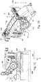
- Figur 1A
- eine Seitenansicht einer Steckverbinderbaugruppe gemäß einer ersten Ausführungsform, deren Hebel in seiner Entriegelungsposition angeordnet ist, und einen davon beabstandeten Steckplatz;
- Figur 1B
- eine perspektivische Ansicht der in Fig. 1A gezeigten Steckverbinderbaugruppe mit Steckplatz;
- Figur 1C
- eine Seitenansicht der in Fig. 1A gezeigten Steckverbinderbaugruppe ohne Schieberführung, in einer auf den Steckplatz aufgesetzten Position;
- Figur 1D
- eine perspektivische Ansicht einer Steckverbinderbaugruppe gemäß der ersten Ausführungsform, deren Hebel in seiner Entriegelungsposition und deren CPA-Einrichtung in ihrer Entsicherungsposition angeordnet ist;
- Figur 2A
- eine Seitenansicht einer Steckverbinderbaugruppe gemäß der ersten Ausführungsform, deren Hebel in seiner Verriegelungsposition angeordnet ist, und die eine Steckverbindung mit einem Steckplatz eingeht;
- Figur 2B
- die in Fig. 2A gezeigte Seitenansicht ohne Schieberführung;
- Figur 3
- eine perspektivische Ansicht eines Hebels der Steckverbinderbaugruppe gemäß der ersten Ausführungsform;
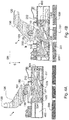
- Figur 4A
- eine Schnittansicht durch die entriegelte und auf den Steckplatz aufgesetzte Steckverbinderbaugruppe gemäß der ersten Ausführungsform;
- Figur 4B
- eine Schnittansicht durch die verriegelte Steckverbinderbaugruppe gemäß der ersten Ausführungsform, die eine Steckverbindung mit dem Steckplatz eingeht;
- Figur 4C
- eine Schnittansicht durch die entriegelte Steckverbinderbaugruppe gemäß der ersten Ausführungsform in einer vorgesicherten und/oder vorbefestigten Aufsetzposition auf dem Steckplatz;
- Figur 5A
- eine perspektivische Ansicht einer Schieberführung der Steckverbinderbaugruppe gemäß der ersten Ausführungsform;
- Figur 5B
- eine Schnittansicht durch die Schieberführung der Steckverbinderbaugruppe gemäß der ersten Ausführungsform;
- Figur 6A
- eine perspektivische Ansicht auf eine Schieberinnenseite eines Schiebers der Steckverbinderbaugruppe gemäß der ersten Ausführungsform mit entspanntem Aufsetzfedermittel;
- Figur 6B
- eine perspektivische Ansicht auf die Schieberinnenseite des Schiebers gemäß der ersten Ausführungsform der Steckverbinderbaugruppe mit ausgelenktem Aufsetzfedermittel;
- Figur 6C
- eine Seitenansicht einer Schieberaußenseite des Schiebers gemäß der ersten Ausführungsform;
- Figur 7A
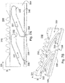
- eine Seitenansicht einer Führungsplatteninnenseite des Schiebers gemäß der ersten Ausführungsform;
- Figur 7B
- eine perspektivische Ansicht auf eine Führungsplattenaußenseite des Schiebers gemäß der ersten Ausführungsform;
- Figur 8A
- eine perspektivische Ansicht auf eine Federplatteninnenseite des Schiebers gemäß der ersten Ausführungsform;
- Figur 8B
- eine perspektivische Ansicht auf eine Federplattenaußenseite des Schiebers gemäß der ersten Ausführungsform;
- Figur 9
- eine Seitenansicht einer Steckverbinderbaugruppe gemäß einer zweiten Ausführungsform, deren Hebel in seiner Entriegelungsposition angeordnet ist, mit einem darunter angeordneten Steckplatz;
- Figur 10A
- eine Seitenansicht einer Steckverbinderbaugruppe gemäß der zweiten Ausführungsform, deren Hebel in seiner Verriegelungsposition angeordnet ist, und die eine Steckverbindung mit einem Steckplatz eingeht;
- Figur 10B
- die in Fig. 10A gezeigte Seitenansicht ohne Schieberführung;
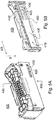
- Figur 11A
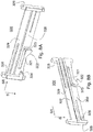
- eine perspektivische Ansicht einer Schieberführung der Steckverbinderbaugruppe gemäß der zweiten Ausführungsform;
- Figur 11B
- eine Schnittansicht durch die Schieberführung der Steckverbinderbaugruppe gemäß der zweiten Ausführungsform;
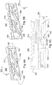
- Figur 12A
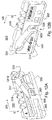
- eine perspektivische Ansicht auf die Außenseite des Schiebers gemäß der zweiten Ausführungsform; und
- Figur 12B
- eine perspektivische Ansicht auf die Innenseite des Schiebers gemäß der zweiten Ausführungsform.
-
Die Figuren 1A und 1B zeigen jeweils eine Seitenansicht und eine perspektivische Ansicht einer Steckverbinderbaugruppe 1 gemäß einer ersten Ausführungsform, welche beabstandet zu einem Steckplatz 500 angeordnet ist. Die Steckverbinderbaugruppe 1 ist mehrteilig aufgebaut und weist insbesondere eine Leiterführungseinrichtung 10, einen Hebel 100 und eine Schieberführung 400 auf. Weiterhin kann die Steckverbinderbaugruppe 1 auch eine in Fig. 1D gezeigte CPA-Einrichtung 200 aufweisen sowie den zumindest einen Schieber 300, welcher z.B. in Fig. 1C gezeigt ist. Die Steckverbinderbaugruppe 1 kann auch als eine CPA-sicherbare Steckverbinderbaugruppe und/oder CPA-Steckverbinderbaugruppe bezeichnet werden.
-
Die Leiterführungseinrichtung 10 bildet dabei einen Grundkörper und/oder ein Grundbauteil der Steckverbinderbaugruppe 1 aus. Die Leiterführungseinrichtung 10 kann ein Gehäuse aufweisen, das in etwa quaderförmig ausgebildet ist, und welches in den Figuren nicht gezeigte elektrische Leiter umschließt und/oder beinhaltet. Diese im Inneren der Leiterführungseinrichtung 10 geführten elektrischen Leiter werden bis zu einer Steckseite 11 (vgl. Fig. 1C und 1D) der Leiterführungseinrichtung 10 geführt. In den Figuren 1A bis 1D ist die Steckseite 11 als die untere Seite der Leiterführungseinrichtung 10 ausgebildet. Die Leiterführungseinrichtung 10 ist dazu ausgebildet, mit der Steckseite 11 voran in Steckrichtung S auf den Steckplatz 500 gesteckt zu werden, um elektrische Verbindungen zwischen den geführten elektrischen Leitern und elektrischen Kontakten des Steckplatzes 500 herzustellen, also um eine Steckverbindung zwischen der Leiterführungseinrichtung 10 und dem Steckplatz 500 herzustellen. Die Steckrichtung S ist dabei etwa senkrecht zur Steckseite 11 ausgebildet.
-
Dabei kann die Leiterführungseinrichtung 10 entweder unmittelbar mit ihrer Steckseite 11 auf den Steckplatz 500 gesteckt werden oder mittelbar, nämlich indirekt mittels der Schieberführung 400 als Zwischenelement. In der gezeigten Ausführungsform wird die Leiterführungseinrichtung 10 mit ihrer Steckseite 11 zunächst mit einer ersten (hier: oberen) Seite der Schieberführung 400 verbunden, welche wiederum mit einer zweiten (hier: unteren) Seite auf den Steckplatz 500 gesteckt wird. Dabei kann diese zweite Seite der Schieberführung 400 der ersten Seite z.B. abgewandt und/oder gegenüberliegend angeordnet sein. Insbesondere kann die zweite Seite der Schieberführung 400 die Schieberführung 400 in Steckrichtung S begrenzen.
-
Die Leiterführungseinrichtung 10 erstreckt sich im Wesentlichen von der Steckseite 11 bis hin zu einer Befestigungsseite 12, welche die Leiterführungseinrichtung 10 in einer der Steckseite 11 abgewandten Richtung begrenzt. Allgemein ist die Befestigungsseite 12 diejenige Seite der Leiterführungseinrichtung 10, auf welche der Hebel 100 in seiner Verriegelungsposition angelegt wird und/oder an welcher die CPA-Einrichtung 200 befestigt ist. Die Befestigungsseite 12 kann etwa senkrecht zur Steckrichtung S angeordnet sein.
-
Der Steckplatz 500 weist im gezeigten Ausführungsbeispiel eine Basisplatte auf, aus der eine Buchse 510 gegen die Steckrichtung S herausragt. Die Buchse 510 wird in der Steckverbindung zumindest teilweise von der Schieberführung 400 umgriffen. Die Buchse 510 weist an einander gegenüberliegenden Außenseiten mehrere Eingriffsvorsprünge 520 auf, von denen lediglich zwei in den Figuren 1A und 1B gezeigt sind. An einer abgewandten Seite kann die Buchse 510 zwei weitere Eingriffsvorsprünge 520 aufweisen, die in entgegengesetzte Richtung von der Buchse 510 abstehen. Im gezeigten Ausführungsbeispiel weist die Buchse 510 also jeweils genau zwei Eingriffsvorsprünge 520 an einander gegenüberliegenden und abgewandten Außenflächen auf. Die Eingriffsvorsprünge 520 sind dazu ausgebildet und vorgesehen, in den in Figur 1C gezeigten Schieber 300 so einzugreifen, dass ein Formschluss zwischen dem Schieber 300 und den Eingriffsvorsprüngen 520 der Buchse 510 bereitgestellt wird. Dies führt zu einer formschlüssigen Verbindung zwischen der ganzen Steckverbinderbaugruppe 1 und dem Steckplatz 500.
-
In einer alternativen Ausführungsform kann der Steckplatz 500 mehr oder weniger Eingriffsvorsprünge 520 aufweisen. Weiterhin kann in einer alternativen Ausführungsform vorgesehen sein, dass die Eingriffsvorsprünge 520 nicht nach außen, genauer in zwei einander gegenüberliegende Außenrichtungen, weisen, sondern nach innen. In dieser Ausführungsform wird/werden auch der oder die Schieber 300 nicht an einer Außenfläche der Buchse 510, sondern an einer Innenfläche der Buchse 510 angeordnet.
-
Figur 1C zeigt eine Seitenansicht der Steckverbinderbaugruppe 1 gemäß der ersten Ausführungsform, wobei die Schieberführung 400 der Anschaulichkeit halber weggelassen ist. Im Inneren der Schieberführung 400 ist der Schieber 300 der Steckverbinderbaugruppe beweglich gelagert. Der Schieber 300 ist als ein weiteres Bauteil der Steckverbinderbaugruppe 1 ausgebildet. Dabei ist der Schieber 300 so an den Hebel 100 gekoppelt, dass der Schieber 300 beim Bewegen des Hebels 300 mitbewegt wird. In Fig. 1C ist die Steckverbinderbaugruppe 1 im Gegensatz zu den Figuren 1A und 1B in einer auf den Steckplatz 500 aufgesetzten Position gezeigt. In dieser aufgesetzten Position umgibt die (in der Figur 1C weggelassene) Schieberführung 400 die Buchse 510 des Steckplatzes 500 zumindest teilweise.
-
Die gezeigte Ausführungsform der Steckverbinderbaugruppe 1 weist zwei Schieber 300 auf, welche an einander abgewandten Außenseiten der Steckverbinderbaugruppe 1 angeordnet sind, nämlich im Inneren der in den Figuren 1A und 1B gezeigten Schieberführung 400. Der Schieber 300 ist im Wesentlichen plattenförmig ausgebildet und weist an einer ersten Plattenseite eine Schieberverzahnung 310 auf. Die Schieberverzahnung 310 besteht aus mehreren Zähnen, welche zum Beispiel gegen die Steckrichtung S von der dem Hebel 100 zugewandten Seite des Schiebers 300 abstehen.
-
Die Schieberverzahnung 310 greift in eine Hebelverzahnung 150 des Hebels 100 ein. Beim Verschwenken des Hebels 100 um den in den Figuren 1A bis 1D gezeigten Schwenkpunkt 110 greifen die Verzahnungen 150, 310 des Hebels 100 und des Schiebers 300 so ineinander ein, dass der Schieber 300 in Schieberichtung SR verlagert wird. Die Verlagerung des Schiebers 300 relativ zur Leiterführungseinrichtung 10 und/oder der Schieberführung 400 bewirkt die Verriegelung der Steckverbinderbaugruppe 1 am Steckplatz 500, also eine formund/oder kraftschlüssige Verbindung der Steckverbinderbaugruppe 1 am Steckplatz 500.
-
Die Schieberichtung SR ist dabei im Wesentlichen senkrecht zur Steckrichtung S ausgerichtet. Weiterhin ist die Schieberichtung SR im Wesentlichen parallel zu einer Außenfläche der Leiterführungseinrichtung 10 angeordnet, zum Beispiel in etwa parallel zu einer Seitenfläche 17, an welcher auch der Hebel 100 an der Leiterführungseinrichtung 10 befestigt ist. Die Schieberichtung SR kann auch in etwa parallel zu einer Außenfläche der Buchse 510 des Steckplatzes 500 angeordnet sein (vgl. Figuren 1A und 1B), an welcher der Schieber 300 in der Steckverbindung anliegt.
-
In alternativen Ausführungsformen kann die Steckverbinderbaugruppe 1 mehr als zwei Schieber oder nur einen Schieber 300 aufweisen. In einer alternativen Ausführungsform weist der Schieber 300 zumindest einen Eingriffsvorsprung auf, während an der Buchse 510 Führungsaussparungen für diesen zumindest einen Eingriffsvorsprung angeordnet sind. Mit anderen Worten ist es für die Wirkungsweise nicht zwingend entscheidend, in welcher Richtung und wie viele Eingriffsvorsprünge vorhanden sind, genauso wenig ob die Eingriffsvorsprünge von der Buchse 510 oder vom Schieber 300 in das jeweilige Gegenstück eingreifen oder umgekehrt. In einer Ausführungsform kann sowohl der Schieber 300 als auch die Steckbuchse 510 Eingriffsvorsprünge aufweisen, die in das jeweils andere Gegenstück eingreifen, um die Verriegelung der Steckverbinderbaugruppe 1 am Steckplatz 500 zu bewirken.
-
Der Schieber 300 ist im Wesentlichen plattenförmig ausgebildet und parallel zu der zugeordneten Außenfläche der Buchse 510 angeordnet, welche die zugeordneten Eingriffsvorsprünge 510 aufweist. Der Schieber 300 wird im Wesentlichen anliegend an diese zugehörige Außenseite der Buchse 510 angeordnet, um die Steckverbindung herzustellen.
-
Der Hebel 100 kann grundsätzlich bügelförmig ausgebildet sein. Dabei erstreckt sich der Hebel 100 von dem ersten Schwenkpunkt 110 entlang eines ersten Hebelarms bis hin zum Schwenkende 120, welches einen Bügelkopf ausbildet. Das Schwenkende 120 erstreckt sich etwa parallel zur Schwenkachse SW (vgl. Fig. 3) des Hebels 100 zwischen den von der Schwenkachse SW beabstandeten Hebelarmenden. Von dem Schwenkende 120 erstreckt sich der Hebel 100 weiterhin entlang des zweiten Hebelarms zurück zu dem zweiten Schwenkpunkt 110, welcher in den Figuren verdeckt ist. Während die Schwenkpunkte 110 an gegenüberliegenden Seitenwänden 17 der Leiterführungseinrichtung 10 ausgebildet sind, verbindet das Schwenkende 120 die beiden Hebelarme des Hebels 100 miteinander.
-
In der Verriegelungsposition ist das Schwenkende 120 auf die Befestigungsseite 12 gedrückt, und zwar in einem Raumbereich, der in etwa benachbart zur CPA-Einrichtung 200 angeordnet ist. In den Figuren 2A und 2B ist die CPA-Einrichtung 200 weggelassen und somit nicht gezeigt, genauso wie in den Figuren 1A bis 1C.
-
Figur 1D zeigt eine perspektivische Ansicht der Steckverbinderbaugruppe 1 gemäß der ersten Ausführungsform, deren Hebel 100 in seiner Entriegelungsposition und deren CPA-Einrichtung 200 in ihrer Entsicherungsposition angeordnet ist. Dabei sind in Fig. 1D der Steckplatz 500, die Schieberführung 400 und der Schieber 300 der Anschaulichkeit halber weggelassen.
-
Die Leiterführungseinrichtung 10 kann zumindest zwei Seitenwände 17 aufweisen, welche die Leiterführungseinrichtung 10 zwischen der Steckseite 11 und der Befestigungsseite 12 nach außen begrenzen. Die Seitenwände 17 können etwa parallel zur Steckrichtung S angeordnet sein.
-
An zwei einander abgewandten Seitenwänden 17 ist der Hebel 100 an der Leiterführungseinrichtung 10 befestigt. Dabei ist der Hebel 100 um zwei Schwenkpunkte 110 verschwenkbar, von denen lediglich einer in Figur 1D gezeigt ist. Der zweite Schwenkpunkt 110 ist an der dem Betrachter abgewandten Seitenwand 17 ausgebildet. Normalen auf diese beiden Seitenwände 17, an welchen der Hebel 100 an der der Leiterführungseinrichtung 10 befestigt, können eine laterale Richtungen definieren. Diese lateralen Richtungen sind etwa senkrecht zur Steckrichtung S angeordnet, etwa parallel zur Steckseite 11, und hier auch etwa senkrecht zur Steckrichtung SR.
-
In der in Figuren 1A bis 1D gezeigten Situation ist der Hebel 100 in seiner Entriegelungsposition angeordnet, in welcher er sich an zumindest einem Entriegelungsanschlag 14 abstützt. Der Entriegelungsanschlag 14 kann an einer oder mehreren der Seitenwände 17 ausgebildet sein. Der Entriegelungsanschlag 14 begrenzt die Schwenkbewegung des Hebels 100 in der Entriegelungsposition.
-
Der Hebel 100 weist ein Schwenkende 120 auf, welches an einem von den Schwenkpunkten 110 beabstandeten Ende des Hebels 100 angeordnet ist. Der Hebel 100 ist so an der Leiterführungseinrichtung 10 befestigt, dass sein Schwenkende 120 um die Schwenkpunkte 110 herum verschwenkbar ist, insbesondere verschwenkbar auf die Befestigungsseite 12 der Leiterführungseinrichtung 10. In der in den Figuren 1A bis 1D gezeigten Entriegelungsposition ist das Schwenkende 120 von der Leiterführungseinrichtung 10 und/oder der Befestigungsseite 12 weggeschwenkt und somit z.B. gegen die Steckrichtung S beabstandet davon angeordnet.
-
Die CPA-Einrichtung 200 ist ebenfalls an der Leiterführungseinrichtung 10 befestigt, und zwar beweglich befestigt. In der in Figur 1D gezeigten Situation ist die CPA-Einrichtung 200 in ihrer Entsicherungsposition angeordnet. Die CPA-Einrichtung 200 ist grundsätzlich verschiebbar entlang eines Teilstücks der Befestigungsseite 12 ausgebildet. In der gezeigten Ausführungsform ist die CPA-Einrichtung 200 jedoch nicht ohne weiteres aus ihrer Entsicherungsposition heraus in die Sicherungsposition verschiebbar, um dadurch nicht unbeabsichtigt ein Verriegeln des Hebels 100 zu blockieren. Wie in Figur 1D gezeigt, kann die CPA-Einrichtung 200 zum Beispiel benachbart zu einer Kabelführung 13 angeordnet sein. Die Leiterführungseinrichtung 10 kann die Kabelführung 13 zum Führen von Kabeln aufweisen, beispielsweise um elektrische Kabel mit den im Inneren der Leiterführungseinrichtung 10 geführten Leitungen elektrisch zu verbinden.
-
Figuren 2A und 2B zeigen in einer Seitenansicht dieselbe Steckverbinderbaugruppe 1 wie die Figuren 1A und 1C. Im Unterschied zu dem in diesen Figuren 1A und 1C gezeigten Zustand ist der Hebel 100 in den Figuren 2A und 2B in seine Verriegelungsposition verschwenkt. Durch das Bewegen des Hebels 100 von der in den Figuren 1 gezeigten Entriegelungsposition in die in den Figuren 2 gezeigte Verriegelungsposition kann der Hebel 100 z.B. an seinem Schwenkende 120 um den zumindest einen Schwenkpunkt 110 herum auf eine Außenfläche der Leiterführungseinrichtung 10 verschwenkt werden, hier auf die Befestigungsseite 12. Beim Verschwenken des Hebels 100 von der Entriegelungsposition in die Verriegelungsposition, also beim Verriegeln des Hebels 100 und der Steckverbinderbaugruppe 1, wird/werden der oder die Schieber 300 in Steckrichtung SR relativ zur Leiterführungseinrichtung 10, relativ zur Schieberführung 400 und relativ zum Steckplatz 500 so verlagert, bewegt und/oder verschoben, dass die Steckverbinderbaugruppe 1 eine form- und/oder kraftschlüssige Verbindung mit dem Steckplatz 500 eingeht.
-
Während die Steckverbinderbaugruppe 1 in der in den Figuren 1A bis 1D gezeigten Entriegelungsposition mit der Unterseite der Schieberführung 400 voran auf den Steckplatz 500 aufgesteckt und/oder aufgesetzt werden kann, so ist diese lose aufgesteckte Position noch nicht vorriegelt und damit relativ einfach vom Steckplatz lösbar. Erst nach einem Verriegeln der Steckverbinderbaugruppe 1, also beim Bewegen des Hebels 100 in die in den Figuren 2A und 2B gezeigte Verriegelungsposition, ist die Steckverbinderbaugruppe 1 so fest mit dem Steckplatz 500 verbunden, dass sie nicht mehr zerstörungsfrei davon lösbar ist.
-
In der Verriegelungsposition kann zumindest eine an der Seitenwand 17 der Leiterführungseinrichtung 10 ausgebildete Verriegelungsnase 15 in eine Aussparung des Hebels 100 greifen und den Hebel zumindest etwas mit einer Hebellösekraft sichern. Hierbei kann es sich lediglich um eine leicht lösbare Sicherung handeln, nicht um eine für den Automotive Bereich hinreichend stabile Sicherung. Eine hinreichend starke Sicherung gegen unbeabsichtigte Hebellösekräfte von z.B. mehr als 100 N und/oder 200 N kann mittels der in Figur 1D gezeigten CPA-Einrichtung 200 bereitgestellt werden.
-
In der in den Figuren gezeigten Ausführungsform ist der Hebel 100 verschwenkbar um eine Schwenkachse, welche in etwa parallel zur Steckseite 1 (vgl. Figur 1D und 1C) in laterale Richtung angeordnet ist. Diese Schwenkachse SW ist zum Beispiel in Figur 3 durch eine gestrichelte Linie gekennzeichnet. Die Schwenkachse SW erstreckt sich durch die Leiterführungseinrichtung 10 hindurch durch die beiden Schwenkpunkte 110 des Hebels 100. Die gezeigte Befestigung des Hebels 100 an den zwei Schwenkpunkten 110, also an den zwei einander abgewandten Seitenwänden 17 der Leiterführungseinrichtung 10, erhöht die Stabilität und Langlebigkeit der Hebelbewegung. In einer alternativen Ausführungsform konnte der Hebel auch lediglich an einem einzigen Schwenkpunkt 110, zum Beispiel nur an einer Seitenwand 17, mit der Leiterführungseinrichtung 10 verschwenkbar verbunden sein.
-
Wie in den Figuren 2A und 2B gezeigt, ist die gesamte Steckverbinderbaugruppe 1 in der verriegelten Position weiter auf den Steckplatz 500 aufgedrückt und/oder darauf hin in Steckrichtung S zubewegt als zum Beispiel in der in Figur 1C gezeigten aufgesetzten und entriegelten Position. Dies wird dadurch bewegt, dass beim Verriegeln der Steckverbinderbaugruppe 1 nicht nur der Schieber 300 in die in Figur 2B gezeigte Verbindungsposition bewegt wird, also entlang Schieberichtung SR relativ zum Rest der Steckverbindergruppe 1, sondern zugleich noch die gesamte Steckverbinderbaugruppe 1 in Steckrichtung S weiter auf den Steckplatz 500 zubewegt wird.
-
In Figur 2B ist gezeigt, dass der Schieber 300 in seiner Verbindungsposition angeordnet ist, also an einer in Schieberichtung SR endseitigen Position seiner Bewegungsfreiheit, in welcher der Schieber 300 die Steckverbinderbaugruppe 1 verriegelt. Im Gegensatz dazu ist der Schieber 300 in der in Figur 1C gezeigten Position in seiner Entnahmeposition angeordnet. In der Entnahmeposition ist der Schieber 300 entgegen der Schieberichtung SR an seinem dortigen Endanschlag angeordnet. Die Bewegung des Schiebers 300 von der in Figur 1C gezeigten Entnahmeposition in die in Figur 2B gezeigte Verbindungsposition ist im Wesentlichen eine Linearbewegung in Schieberichtung SR relativ zum Recht der Steckverbinderbaugruppe 1, insbesondere zur Leiterführungseinrichtung 10, der Schieberführung 400 und der gegebenenfalls vorhandenen CPA-Einrichtung 200 (vgl. Figur 1D). Die Relativbewegung erfolgt auch relativ zum Schwenkpunkt 110 und zu einem Großteil des Hebels 100. Da der Hebel 100 gleichzeitig um die Schwenkachse SW verschwenkt wird (vgl. Figur 3), stellt dies keine reine Relativbewegung ist. Diese Schiebebewegung zwischen der Entnahmeposition und der Verbindungsposition ist reversibel und ist im Inneren der Schieberführung 400 geführt.
-
Figur 3 zeigt eine perspektivische Ansicht des Hebels 100 der Steckverbinderbaugruppe 1 gemäß der ersten Ausführungsform. Der Hebel 100 ist bezüglich seiner Schwenkachse SW verschwenkbar an der Steckverbinderbaugruppe 1 angeordnet und befestigt. Die Schwenkachse SW erstreckt sich dabei durch die beiden Schwenkpunkte 110, welche im assemblierten Zustand an gegenüberliegenden Seiten, genauer an den Seitenwänden 17, der Leiterführungseinrichtung 10 angeordnet sind.
-
Der Hebel 100 weist zwei Hebelarme 140 auf, welche sich jeweils in etwa von einem der Schwenkpunkte 110 zum Schwenkende 120 erstrecken. In jedem der Hebelarme 140 kann eine Rastaufnahme 141 als eine Aussparung ausgebildet sein, welche zum Aufnehmen der in den Figuren 2A und 2B gezeigten Verriegelungsnase 15 ausgebildet ist.
-
In der Nähe und/oder benachbart zu der Schwenkachse SW ist an den Hebelarmen 140 jeweils eine Hebelverzahnung 150 ausgebildet. Die Hebelverzahnung 150 ist an einem Hebelende 151 des Hebels 100 ausgebildet, welches so angeordnet ist, dass es dem Schwenkende 120 bezüglich der Schwenkachse SW und/oder bezüglich des zugeordneten Schwenkpunkts 110 abgewandt ist. Das Hebelende 151 ist an dem Ende des Hebels 100 angeordnet, welches von der Schwenkachse SW und/oder vom Schwenkpunkt 110 zum Schieber 300 und/oder zum Steckplatz 500 weist (vgl. auch Figuren 1C und 2B).
-
Die Hebelverzahnung 150 kann mehrere Zähne umfassen und insbesondere ähnlich eines Teilstücks eines Zahnrads ausgebildet sein. Die Hebelverzahnung 150 ist dazu konfiguriert, in die z.B. in den Figuren 1C und 2B gezeigte Schieberverzahnung 310 derart einzugreifen, dass eine sichere Verriegelung der Steckverbinderbaugruppe 1 am Steckplatz 500 erfolgen kann. Die Hebelverzahnung 150 ist dabei jeweils an dem dem Schwenkende 120 abgewandten Hebelsende 151 der Hebelarme 140 angeordnet.
-
Am Schwenkende 120 weist der Hebel 100 eine Auflagefläche 160 auf. Die Auflagefläche 160 ist bezüglich der Erstreckungsrichtung der Hebelarme 140 leicht abgewinkelt. Die Auflagefläche 160 ist dabei so bezüglich der Hebelarme 140 abgewinkelt, dass sie in der in den Figuren 2A und 2B gezeigten Verriegelungsposition des Hebels 100 in etwa parallel zur Außenfläche der Leiterführungseinrichtung 10, genauer der Befestigungsseite 12, ausgebildet und ausgerichtet ist. Dadurch kann die Auflagefläche 160 in der Verriegelungsposition zumindest teilweise flächig auf die Befestigungsseite 12 aufgelegt sein, vgl. Figuren 2A und 2B.
-
Am Schwenkende 120 ist weiterhin in etwa mittig des Hebels 100 eine Vorsprungzunge 130 ausgebildet. Die Vorsprungzunge 130 kann denjenigen Hebelpunkt des Hebels 100 umfassen, welcher am weitesten von der Schwenkachse SW beabstandet ist. Die Vorsprungzunge 130 kann als eine Verlängerung des Schwenkendes 120 und/oder der Auflagefläche 160 in etwa in Richtung von der Schwenkachse SW weg ausgebildet sein. Die Vorsprungzunge 130 ist in der Verriegelungsposition im Wesentlichen parallel zu und/oder zumindest teilweise aufliegend auf der Befestigungsseite 12 angeordnet. Die Vorsprungzunge 130 kann den am weitesten von den Schwenkpunkten 110 beabstandeten Punkt des Hebels 100 umfassen. Die Vorsprungzunge 130 kann in der Sicherungsposition einen Formschluss mit der CPA-Einrichtung 200 bilden, um so den verriegelten Hebel 100 an dem Steckverbinder 1 zu sichern.
-
Figur 4A zeigt eine Schnittansicht durch die entriegelte und auf den Steckplatz 500 aufgesetzte Steckverbinderbaugruppe 1 gemäß der ersten Ausführungsform. Die Schnittansicht zeigt einen Schnitt durch den Schieber 300, in einer Ebene parallel zur Steckrichtung S und zur Schieberichtung SR. Hierbei wird von einem im Inneren der Buchse 510 angeordneten Standpunkt nach außen auf die Schnittebene geschaut, welche durch den in der Schieberführung 400 geführten Schieber 300 verläuft. Im gezeigten Schnitt ist vom Steckplatz 500 lediglich eine Platte zu sehen sowie die sich in Betrachtungsrichtung erstreckenden Eingriffsvorsprünge 520, welche sich vom Betrachter weg in die Zeichenebene hinein erstrecken.
-
Die beiden in etwa auf gleicher Höhe in Steckrichtung S angeordneten Eingriffsvorsprünge 520 sind an einem Eingang einer jeweils zugeordneten Führungsaussparung 331 angeordnet. Jeder Schieber 300 weist genau zwei solcher Führungsaussparungen 331 auf. Jede einzelne der Führungsaussparungen 331 ist zur Aufnahme und zum Führen jeweils eines der Eingriffsvorsprünge 520 des Steckplatzes 500 ausgebildet und konfiguriert. Dabei ist die Innendimensionierung der Führungsaussparungen 331 auf den Außendurchmesser und/oder die Außendimensionierung der Eingriffsvorsprünge 520 so abgestimmt, dass der zugeordnete Eingriffsvorsprung 520 im Wesentlichen spielfrei im Inneren der zugeordneten Führungsaussparung 331 führbar ist.
-
In dem in Figur 4A gezeigten Zustand ist die Steckverbinderbaugruppe 1 lediglich lose auf den Steckplatz 500 aufgesetzt, wobei die insgesamt vier Eingriffsvorsprünge 520 des Steckplatzes 500 (von denen in Figur 4A lediglich zwei gezeigt sind) in vier Eingangsöffnungen der insgesamt vier Führungsaussparungen 331 der zwei Schieber 300 eingefädelt sind. Dabei kann zumindest ein Eingriffsvorsprung 520 an einer Steckrichtungs-Seite eines Aufsetzlagervorsprungs 324 des Schiebers 300 anliegen, welcher zunächst ein weiteres Eindringen dieses Eingriffsvorsprungs 520 in die Führungsaussparung 331 blockiert. Der Aufsetzlagervorsprung 324 ragt so in zumindest eine der Führungsaussparungen 331 hinein, dass der Eingriffsvorsprung 520 nicht ohne weiteres und/oder widerstandslos ins Innere der zugeordneten Führungsaussparung 331 eingeführt werden kann. Der Aufsetzlagervorsprung 324 ist gegen eine Federbelastung jedoch so verlagerbar, dass er die Führungsaussparung 331 freigibt und der Eingriffsvorsprung 520 weiter ins Innere der Führungsaussparung 331 eingeführt werden kann.
-
Da die Steckverbinderbaugruppe 1 in dem in Figur 4A gezeigten Zustand im Wesentlichen widerstandsfrei, gegebenenfalls lediglich gegen die wirkende Gravitationskraft, vom Steckplatz 500 entnehmbar ist, wird der in Figur 4A gezeigte Zustand auch als ein lose aufgesetzter Zustand der Steckverbinderbaugruppe 1 bezeichnet, oder auch als lose und/oder unbefestigte Aufsetzposition.
-
In Figur 4A ist der Schieber 300 in seiner Entnahmeposition angeordnet. Die Entnahmeposition des Schiebers 300 zeichnet sich zum Beispiel dadurch aus, dass die Steckverbinderbaugruppe 1 vom Steckplatz 500 lösbar ist. Weiterhin ist der Schieber 300 in seiner Entnahmeposition an einem Ende im Inneren der Schieberführung 400 angeordnet, welches in der in Figur 4A gezeigten Situation das rechte Ende darstellt. Der Schieber 300 ist also an dem Ende angeordnet, das seine Bewegungsfreiheit gegen die Schieberichtung SR im Inneren der Schieberführung 400 begrenzt. Hier kann die Schieberführung 400 zum Beispiel einen Anschlag aufweisen, der verhindert, dass der Schieber 300 weiter gegen die Schieberichtung SR verlagerbar ist relativ zur Schieberführung 400 und somit auch dem Rest der Steckverbinderbaugruppe 1. Im Inneren der Schieberführung 400 kann der Schieber 300 eine Linearbewegung in und gegen die Schieberichtung SR ausführen, welche allerdings auf das Innere der Schieberführung 400 begrenzt ist. Es kann also entlang dieser Linearbewegung Anschläge in einander abgewandten Enden geben, insbesondere in der Entnahmeposition und in der Verbindungsposition. Die Schieberichtung SR kann hierbei in etwa parallel zu einer Steckseite 11 der Steckverbinderbaugruppe 1 und/oder auch einer Steckaufnahmefläche des Steckplatzes 500 angeordnet sein.
-
Figur 4B zeigt denselben Ausschnitt wie Figur 1 der Steckverbinderbaugruppe 1 gemäß der ersten Ausführungsform, wobei hier der Hebel 100 in seiner Verriegelungsposition angeordnet ist. Der Hebel 100 kann von der in Figur 4A gezeigten Entriegelungsposition um den Schwenkpunkt 110 herum in die in Figur 4B gezeigte Verriegelungsposition verschwenkt werden. Diese Bewegung kann zum Beispiel dadurch begrenzt sein, dass das Schwenkende 120 auf die Befestigungsseite 12 der Leiterführungseinrichtung 10 aufgelegt wird, vgl. auch Figuren 2A und 2B. Die Leiterführungseinrichtung 10 ist in den Figuren 4 jedoch nicht gezeigt, da der Schnitt in einer Ebene parallel zur Seitenfläche 17 der Leiterführungseinrichtung 10 und außerhalb der Leiterführungseinrichtung 10 gelegt ist, nämlich durch die Erstreckungsebene des Schiebers 300.
-
Durch Bewegung des Hebels 100 in seine Verriegelungsposition wird auch der Schieber 300 in seine Verbindungsposition verlagert, nämlich durch eine Linearbewegung in Schieberichtung SR relativ zum Rest der Steckverbinderbaugruppe 1. Die Bewegung des Hebels 100 ist über die Hebelverzahnung 150 und die Schieberverzahnung 310 an den Schieber 300 gekoppelt. Hierbei wird die Schwenkbewegung des Hebels 100 um den Schwenkpunkt 110 über die Verzahnungen 150 und 310 in eine Linearbewegung des Schiebers 300 in Schieberichtung SR übersetzt. In der in Figur 4B gezeigten Verbindungsposition ist der Schieber an einem anderen Ende im Inneren der Schieberführung 400 angeordnet als in der in Figur 4A gezeigten Entnahmeposition.
-
Beim Verschieben des Schiebers 300 in Schieberichtung SR werden die Eingriffsvorsprünge 520 entlang der Führungsaussparungen 331 weiter ins Innere des Schiebers 300 geführt bis hin zu einem Verbindungsende 332. In der Verbindungsposition ist jeder der Eingriffsvorsprünge 520 in einem jeweils zugeordneten Verbindungsende 332 der Führungsaussparung 331 so angeordnet, dass jeweils ein Formschluss in Steckrichtung S besteht zwischen dem Eingriffsvorsprung 520 und dem Schieber 300.
-
Die Führungsaussparungen 331 weisen einen Eingang in Steckrichtung S auf, in welchem die Eingriffsvorsprünge 520 in die in Figur 4A gezeigten Situation einführbar sind. Die Eingänge weisen dabei in Steckrichtung S vom Schieber 300 in Richtung zum Steckplatz 500. Die Eingangsöffnungen sind so ausgebildet und angeordnet, dass die Eingriffsvorsprünge 520 leicht eingeführt werden können. Sie können zum Beispiel in Steckrichtung aufgeweitet sein, um das Einfädeln zu erleichtern. Von diesen Eingängen verlaufen die Führungsaussparungen 331 zunächst ein Stück weit entgegen der Steckrichtung S ins Innere des Schiebers 300, dann nach einem Richtungswechsel sowohl schräg zur Steckrichtung S als auch schräg zur Schieberichtung SR weiter ins Innere des Schiebers 300 bis hin zu den Verbindungsenden 332. Die Verbindungsenden 332 können im Wesentlichen parallel zur Schieberichtung SR und/oder im Wesentlichen senkrecht zur Steckrichtung S verlaufen.
-
Zwischen dem Eingang und den Verbindungsenden 332 sind die Führungsaussparungen 331 entlang zumindest eines Teilstücks sowohl relativ zut Steckrichtung S als auch relativ zur Schieberichtung SR geneigt. In diesem Teilstück können die Führungsaussparungen 331 einen Winkel von etwa 80° bis etwa 30° zur Steckrichtung S ausbilden, bevorzugt von etwa 80° bis etwa 45° zur Steckrichtung S. Weiterhin können sie einen Winkel von etwa 10° bis etwa 60° zur Schieberichtung SR ausbilden, bevorzugt von etwa 10° bis etwa 45° zur Steckrichtung SR.
-
Diese schräge Anordnung der Führungsaussparungen 331 bewirkt einerseits, dass die Eingriffsvorsprünge 520 beim Verriegeln gegen die Steckrichtung S weiter ins Innere des Schiebers 300 und der Schieberführung 400 geführt werden, und andererseits eine Verlagerung des Schiebers 300 in Schieberichtung SR. Somit führt die Form und die Verlaufsrichtung der Führungsaussparung 331 zu der in Figur 4B gezeigten verriegelten Position, in welcher der Schieber 300 in seiner Verbindungsposition angeordnet ist. Damit ist die Steckverbinderbaugruppe 1 fest mit dem Steckplatz 500 verbunden.
-
Figur 4C zeigt einen Zwischenzustand zwischen den beiden in den Figuren 4A und 4B gezeigten Zuständen. Der in Figur 4C gezeigte Zustand kann auch als ein vorverbundener und/oder vorbefestigter Aufsetzzustand, als ein "pre-mating" Zustand oder auch als ein fest aufgesetzter Zustand der Steckverbinderbaugruppe 1 bezeichnet werden.
-
Ausgehend von der in Figur 4A gezeigten Situation, also dem lose und/oder unbefestigt aufgesetztem Zustand der Steckverbinderbaugruppe 1 wird diese zunächst leicht in Steckrichtung S angedrückt an den Steckplatz 500. Dabei wird der Eingriffsvorsprung 520 gegen die Steckrichtung S in die Führungsaussparung 331 hineingedrückt, wo er auf den Aufsatzlagervorsprung 324 drückt. Dann verlagert sich der Aufsatzlagervorsprung 324 gegen eine Federkraft aus der Führungsaussparung 331 hinaus und lässt den Eingriffsvorsprung 520 weiter eindringen in die Führungsaussparung 331. Passiert der Eingriffsvorsprung 520 den Aufsetzlagervorsprung 324, so kann dieser (bewirkt von der Federkraft) zurückschwingen in den Eingang der Führungsaussparung 331. Dieser zurückgeschwungene Zustand des Aufsetzlagervorsprungs 324 ist in Figur 4C gezeigt. In diesem Zustand blockiert der Aufsetzlagervorsprung 324 ein unbeabsichtigtes Bewegen des zugeordneten Eingriffsvorsprungs 520 aus der Führungsaussparung 331 hinaus. Damit ist die Steckverbinderbaugruppe 1 zumindest gegen die Federspannung des Aufsetzlagervorsprungs 324 am Steckplatz 500 gesichert. Dadurch wird ein fest aufgesetzter Zustand oder auch vorverbundener Aufsetzzustand erreicht, von welchem aus die Steckverbinderbaugruppe 1 einfach verriegelt werden kann, zum Beispiel mit einer einzigen Hand einer Bedienperson.
-
Dabei ist auch in dem fest aufgesetzten Zustand, welcher in Figur 4C gezeigt ist, der Schieber 300 an sich noch immer in seiner Entnahmeposition angeordnet. So kann die Steckverbinderbaugruppe 1 aus dieser Position noch immer gegen die Federkraft des Aufsetzlagervorsprungs 324 vom Steckplatz 500 gelöst werden. Nur die Eingriffsvorsprünge 520 sind etwas weiter ins Innere der Führungsaussparung 131 eingeführt, nämlich bis zu einem dem Eingang abgewandten Ende des zunächst gegen die Steckrichtung S verlaufenden ersten Teilabschnitts der Führungsaussparung 331. Von hier aus können sie einfach entlang des schrägen Teilstücks weiter ins Innere des Schiebers 300 verlagert werden.
-
Figur 5A zeigt eine perspektivische Ansicht der Schieberführung 400 der Steckverbinderbaugruppe 1 gemäß der ersten Ausführungsform. Die Schieberführung 400 ist im Wesentlichen quaderförmig aufgebaut und weist eine Mehrzahl Durchgangsöffnungen für die im Inneren der Leiterführungseinrichtung 10 geführten elektrischen Leiter auf und/oder für elektrische Kontakte des Steckplatzes 500. Die Schieberführung 400 ist als ein Verbindungsstück zwischen der Leiterführungseinrichtung 10 und dem Steckplatz 500 ausgebildet und konfiguriert. Dabei weist die Schieberführung 400 eine Steckerseite 440 auf, welche die Schieberführung 400 entgegen der Steckrichtung S begrenzt und welche der Steckseite 11 der Leiterführungseinrichtung 10 zugewandt ist (vgl. zum Beispiel Figur 1B). In Steckrichtung S wird die Schieberführung 400 von einer Steckplatzseite 450 begrenzt. Die Steckverbinderbaugruppe 1 ist dazu ausgebildet und konfiguriert, mit dieser Steckplatzseite 450 voran in Steckrichtung S auf den Steckplatz 500 gesteckt zu werden.
-
Die Schieberführung 400 dient nicht nur als Bindeglied zwischen der Leiterführungseinrichtung 10 und dem Steckplatz 500, sondern auch zur Führung der beiden Schieber 300, die entlang zwei einander abgewandten Seitenflächen der Schieberführung 400 verschiebbar im Inneren der Schieberführung 400 gelagert sind.
-
Figur 5B zeigt einen Schnitt durch die Schiebervorrichtung 400 an einer eher dem Betrachter abgewandten Seite der Schiebervorrichtung 400 gemäß der ersten Ausführungsform. An dieser Seite weist die Schieberführung 400 einen Schieberführungsraum 430 auf. Dieser Schieberführungsraum 430 ermöglicht die Schiebebewegung des Schiebers 300 in Schieberichtung SR (vgl. zum Beispiel Figuren 4). Der Schieberführungsraum 430 ist in Steckrichtung S von einer Unterkante begrenzt, gegen die Steckrichtung S von einer Oberkante, und vom Betrachter weg von einer Außengehäusefläche der Schieberführung 400.
-
Weiterhin können die Ober- und Unterkante Übergriffe aufweisen, welche auch die Bewegung des Schiebers 300 in einer den Betrachter zugewandten Richtung unterbinden und/oder begrenzen. Allgemein ist der Schieberführungsraum 430 so von Elementen der Schieberführung 400 umgeben, dass der Schieber 300 im Inneren des Schieberführungsraums 430 lediglich etwa eine Linearbewegung ausführen kann, nämlich die Linearbewegung in und gegen die Schieberichtung SR.
-
An der den Schieberführungsraum 430 lateral nach außen begrenzenden Außenfläche der Schieberführung 400 ist eine Halteöffnung 420 und eine Haltungsführung 425 ausgebildet. Die Haltungsführung 425 verläuft parallel zur Schieberichtung SR. Die Halteöffnung 420 und die Haltungsführung 425 sind als Aussparungen in der zugeordneten Außenwand der Schieberführung 400 ausgebildet, welche in assemblierter Position im Wesentlichen benachbart und parallel zum Schieber 300 angeordnet ist. Die Halteöffnung 420 dient zur Aufnahme eines zum Beispiel in Figur 1C gezeigten Haltefedermittels 325 des Schiebers 300. Das Haltefedermittel 325 steht vom Schieber 300 in eine nach außen weisende Richtung ab, welche sowohl senkrecht zur Schieberichtung SR als auch zur Steckrichtung S ausgebildet ist. Die Halteöffnung 420 dient zur Aufnahme dieses Haltefedermittels 325 in Entnahmeposition des Schiebers 300.
-
Aus dieser Entnahmeposition ist der Schieber 300 nur unter Auslenkung des Haltefedermittels 325 ins Innere des Steckers bewegbar. Wird der Schieber 300 in Schieberichtung SR verschoben, so kann sich das Haltefedermittel 325 entlang der Haltungsführung 425 in Schieberichtung SR bewegen, und zwar in einem entspannten Zustand. Das Haltefedermittel 325 dient somit zur Definition der Entnahmeposition des Schiebers 300 und verhindert ein unbeabsichtigtes Verschieben des Schiebers 300 aus der Entnahmeposition heraus, was ein Einfädeln der Eingriffsvorsprünge 520 in die Führungsaussparungen 331 erschweren würde.
-
Figuren 6A und 6B zeigen perspektivische Ansichten des Schiebers 300 gemäß der ersten Ausführungsform in unterschiedlichen Zuständen, während Figur 6C eine Seitenansicht des Schiebers 300 zeigt.
-
Figur 6A zeigt eine perspektivische Ansicht des Schiebers 300 auf eine Innenseite 340 des Schiebers 300. Die Innenseite 340 ist im assemblierten Zustand dem Steckplatz 500 und/oder der Buchse 510 zugewandt und weist grundsätzlich ins Steckerinnere hinein.
-
Der Stecker 300 ist zweiteilig aufgebaut und weist sowohl eine Führungsplatte 330 als auch eine Federplatte 420 auf. Die Plattenebene der Führungsplatte 330 ist im Wesentlichen parallel zur Plattenebene der Federplatte 320 angeordnet. Die beiden Platten 330 und 320 sind relativ zueinander entgegen der Steckrichtung SR verlagerbar. So kann, wenn die Eingriffsvorsprünge 520 in die Eingänge der Führungsaussparungen 331 eingeführt werden, der Aufsetzlagervorsprung 324 zusammen mit der Federplatte 320 relativ zur Führungsplatte 330 gegen die Schieberichtung SR verlagert werden, nämlich in den in Figur 6B gezeigten Zustand. In diesem verlagerten und/oder angespannten Zustand des Schiebers 300 ist der Aufsetzlagervorsprung 324 so aus der zugeordneten Führungsaussparung 331 hinausgedrängt, dass er diese freigibt für die Eingriffsvorsprünge 520 (vgl. Figuren 4A und 4C). Die Verlagerung der Federplatte 320 relativ zur Führungsplatte 330 erfolgt gegen die Federkraft des in Figur 6C gezeigten Aufsetzfedermittels 321. Das Aufsetzfedermittel 321 ist als Bestandteil der Federplatte 320 ausgebildet.
-
Allgemein kann die Führungsplatte 330 sowohl die Schieberverzahnung 310 als auch die Führungsaussparungen 331 aufweisen. Die Federplatte 320 kann zumindest ein Federmittel aufweisen, insbesondere das Aufsetzfedermittel 321 und das Haltefedermittel 325.
-
Figur 6C zeigt eine Seitenansicht auf eine Schieberaußenseite 350 des Schiebers 300 also auf eine von einer zentralen Steckachse abgewandten Seite des Schiebers 300. Die Schieberaußenseite 350 wird im Wesentlichen von einer Federplattenaußenseite 327 gebildet.
-
Das Aufsetzfedermittel 321 ist im Wesentlichen in der Ebene und/oder der Plattenebene der Federplatte 320 ausgebildet. Die Federplatte 320 weist weiterhin einen Federschwenkraum 323 auf, in welchem das Aufsetzfedermittel 321 verschwenkbar ist bei Auslenkung des Aufsetzlagervorsprungs 324 aus der Führungsaussparung 321 hinaus, vgl. Figur 6B. Dazu ist der Federschwenkraum 323 unmittelbar benachbart zum Aufsetzfedermittel 321 angeordnet.
-
Im gezeigten Ausführungsbeispiel ist das Aufsetzfedermittel 321 als ein Schwenkarm ausgebildet, welcher lediglich an einer Basis mit der Federplatte 320 verbunden ist. An einem dieser Basis abgewandten Schwenkende weist das Aufsetzfedermittel 321 eine Verdickung. Dieses verdickte Schwenkende des Aufsetzfedermittels 321 ist in den Federschwenkraum 323 verlagerbar. Die Verlagerung erfolgt unter Zusammenwirkung einer Abschrägung 322 des Aufsetzfedermittels 321 gegen eine Gegenschrägung 323 der Führungsplatte 330.
-
Wird der Eingriffsvorsprung 520 in den Eingang der Führungsaussparung 331 eingeführt, so entsteht aufgrund von Abschrägungen des Aufsetzlagervorsprungs 324 eine Kraft gegen die Schieberichtung SR auf die Federplatte 320. Diese führt dazu, dass die Abschrägung 322 des Aufsetzfedermittels 321 auf der Gegenschrägung 333 reibt, wobei das Aufsetzfedermittel 321 in etwa entgegen der Steckrichtung S in den Federschwenkraum 323 schwenkt. Sowie der Eingriffsvorsprung 520 nicht mehr auf den Aufsetzlagervorsprung 324 einwirkt, entspannt sich das Aufsetzfedermittel 321 wieder, so dass die Federplatte 320 wieder in den in den Figuren 6A und 6B gezeigten Zustand relativ zur Führungsplatte 330 zurückfedert.
-
Figur 7A zeigt eine Seitenansicht auf eine Führungsplatteninnenseite 334 der Führungsplatte 330 gemäß der ersten Ausführungsform. Diese Führungsplatteninnenseite 334 stellt einen Großteil der Schieberinnenseite 340 bereit. Die Führungsplatte 330 erstreckt sich entlang einer Plattenebene in Steckrichtung S von der Schieberverzahnung 310 bis zu einer Steckkante 338, welche die Führungsplatte 330 an einer dem Steckplatz 500 zugewandten Seite begrenzt. In der Steckkante 338 sind zwei Eingänge bzw. Einführanfänge 336 ausgebildet, welche zum Einfädeln der Einsatzvorsprünge 520 des Steckplatzes 500 konfiguriert sind. Angrenzend an die Einführanfänge 336 erstrecken sich die Führungsaussparungen 331 zunächst ein Teilstück entgegen der Steckrichtung S und daran anschließend winklig sowohl zur Steckrichtung S als auch zur Schieberichtung SR bis hin zum Verbindungsende 332 ins Innere der Führungsplatte 330.
-
Figur 7B zeigt eine perspektivische Ansicht der Führungsplatte 330 gemäß der ersten Ausführungsform auf eine Führungsplattenaußenseite 335. Die Führungsplattenaußenseite 335 ist im assemblierten Zustand der Federplatte 320 zugewandt und weist vom Inneren der Steckverbindung weg nach außen. An der Führungsplattenaußenseite 335 weist die Führungsplatte 330 eine Federplattenführung 337 auf. Die Federplattenführung 337 ist als eine schienenartige Vertiefung und/oder Führung ausgebildet, welche zur Aufnahme eines Schienenkörpers 329 der Federplatte 320 ausgebildet ist, vgl. Figuren 8A und 8B. Die Federplattenführung 337 ist in und gegen die Steckrichtung S von einer Kante begrenzt und in und gegen die Schieberichtung SR offen ausgebildet. Die Federplattenführung 337 ermöglicht eine geführte und/oder definierte Relativbewegung der Federplatte 320 relativ zur Führungsplatte 330.
-
An der Kante der Führungsplatte 330, welche die Federplattenführung 337 gegen die Steckrichtung S begrenzt, ist die Schiebeverzahnung 310 ausgebildet. An der Kante der Federplattenführung 337, welche an der Steckkante 338 ausgebildet ist, weist diese Kante sowohl eine Kantenunterbrechung 339 auf als auch die Gegenschrägung 333. Diese dienen zur Interaktion mit dem Schwenkende des Aufsetzfedermittels 321 der Federplatte 320.
-
Figur 8A zeigt eine perspektivische Ansicht der Federplatte 320 gemäß der ersten Ausführungsform, insbesondere einer Federplatteninnenseite 326 der Federplatte 320. Die Federplatteninnenseite 326 ist zum Inneren der Steckverbindung zugewandt angeordnet und liegt im assemblierten Zustand an der Führungsplattenaußenseite 325 an.
-
Die Federplatte 320 weist den sich zwischen zwei Federplattenanschlägen 328 erstreckenden Schienenkörper 329 auf. Der Schienenkörper 329 ist so dimensioniert, dass er im Inneren der Federplattenführung 337 gleitend bewegbar ist, vgl. Figur 7B.
-
Die Federplattenanschläge 328 sind als Verdickungen ausgebildet, welche die Federplatte 320 in und gegen die Schieberichtung SR begrenzen und die im assemblierten Zustand Enden der Führungsplatte 330 in und gegen die Schieberichtung SR umgreifen können. Die Federplattenanschläge 328 dienen zur Begrenzung der Relativbewegung der Federplatte 320 relativ zur Führungsplatte 330. Dazu stehen die Federplattenanschläge 328 von dem Schienenkörper 329 nach innen ab, also senkrecht zur Schieberichtung SR und senkrecht zur Steckrichtung S aus der Plattenebene.
-
Die Federplattenanschläge 328 sind weiter von einander beabstandet als die Führungsplatte 330 in Schieberichtung SR lang ist. Dies ermöglicht ein durch den Zwischenabstand der Federplattenanschläge 328 definiertes Bewegungsspiel der Federplatte 320 relativ zur Führungsplatte 330.
-
Die Führungsplatte 330 kann entweder am schiebeseitigen Federplattenanschlag 328 oder gegenschiebeseitigen anliegen, je nachdem ob das Aufsetzfedermittel 321 gerade entspannt oder gespannt ist. An einem der Federplattenanschläge 328 kann der Aufsetzlagervorsprung 324 so ausgebildet sein, dass er von diesem Federplattenanschläge 328 weg in Schieberichtung SR weist.
-
Figur 8B zeigt eine perspektivische Ansicht einer Federplattenaußenseite 327 der Federplatte 320 gemäß der ersten Ausführungsform welche einen Großteil der Schieberaußenseite 350 ausbildet und/oder bereitstellt. An der Federplattenaußenseite 327 ragt das Haltefedermittel 325 aus der Plattenebene der Federplattenaußenseite 327 nach außen heraus. An der Federplattenaußenseite 327 ragen die Federplattenanschläge 328 nicht aus der Plattenebene des Schienenkörpers 329 heraus, sondern schließen bündig damit ab. Dies ermöglicht ein möglichst reibungsarmes Gleiten entlang der Innenseite der Schieberführung 400.
-
In der gezeigten Ausführungsform ist eine bevorzugte Konfiguration des Schiebers 300 gezeigt. In alternativen Ausführungsformen kann die Führungsplatte als eine äußere Platte des Schiebers 300 ausgebildet sein und die Federplatte als eine innere Platte. In einer alternativen Ausführungsformen kann die Verzahnung 310 an der Federplatte 320 und nicht an der Führungsplatte 330 angeordnet sein
-
Die gezeigte Konfiguration des Schiebers 300 mit der Federplatte 320 und der Schieberplatte 330 ermöglichen ein einfaches Herstellen der Steckverbindung zwischen der Steckverbinderbaugruppe 1 und dem Steckplatz 500. Dazu wird die Steckverbinderbaugruppe 1 zunächst lose auf dem Steckplatz 500 aufgesetzt, z.B. in die in Figur 4A gezeigte lose und unverbundene Aufsteckposition. Anschließend wird die Steckverbinderbaugruppe 1 leicht in Steckrichtung S auf den Steckplatz 500 angedrückt, so dass die Eingriffsvorsprünge 520 den Aufsetzlagervorsprung 324 kurzzeitig verlagern und an diesem vorbei ins Innere der Führungsaussparung 331 eindringen. Dies führt zu der in Figur 4C gezeigten vorbefestigten und/oder vorverbundenen Aufsetzposition der Steckverbinderbaugruppe 1. Anschließend kann der Hebel 100 verriegelt werden, also verschwenkt um den Schwenkpunkt 110 auf die Befestigungsseite 12 der Leiterführungseinrichtung 10.
-
Figur 9 zeigt eine Seitenansicht einer Steckverbinderbaugruppe 1 gemäß einer zweiten Ausführungsform, welche oberhalb eines Steckplatzes 500 angeordnet ist. Wie die Steckverbinderbaugruppe 1 gemäß der ersten Ausführungsform ist auch diese mehrteilig aufgebaut und weist insbesondere eine Leiterführungseinrichtung 10, einen Hebel 100, eine Schieberführung 400, eine CPA-Einrichtung 200 und zumindest einen, bevorzugt zwei, in den nachfolgenden Figuren gezeigte(n) Schieber 300 auf. Die Steckverbinderbaugruppe 1 kann auch als eine CPA-sicherbare Steckverbinderbaugruppe und/oder CPA-Steckverbinderbaugruppe bezeichnet werden.
-
Da die Steckverbinderbaugruppe 1 gemäß der zweiten Ausführungsform sehr ähnlich zu der gemäß der ersten Ausführungsform ausgebildet ist, wird auf deren Beschreibung Bezug genommen, um Wiederholungen zu vermeiden. Tatsächlich trifft ein Großteil der Beschreibung der Steckverbinderbaugruppe 1 gemäß der ersten Ausführungsform auch auf die Steckverbinderbaugruppe 1 gemäß der zweiten Ausführungsform zu und umgekehrt.
-
So bildet auch hier die Leiterführungseinrichtung 10 einen Grundkörper und/oder ein Grundbauteil aus, der ein Gehäuse aufweisen kann, das in etwa quaderförmig ausgebildet ist, und welches in den Figuren nicht gezeigte elektrische Leiter umschließt und/oder beinhaltet. Diese im Inneren der Leiterführungseinrichtung 10 geführten elektrischen Leiter werden bis zu der Steckseite 11 (vgl. Fig. 1C und 1D für die erste Ausführungsform) der Leiterführungseinrichtung 10 geführt, welche in Fig. 9 als eine untere Seite der Leiterführungseinrichtung 10 ausgebildet ist. Die Leiterführungseinrichtung 10 ist dazu ausgebildet, mit der Steckseite 11 voran in Steckrichtung S auf den Steckplatz 500 gesteckt zu werden, um elektrische Verbindungen zwischen den geführten elektrischen Leitern und elektrischen Kontakten des Steckplatzes 500 herzustellen, also um eine Steckverbindung zwischen der Leiterführungseinrichtung 10 und dem Steckplatz 500 herzustellen. Die Steckrichtung S ist dabei etwa senkrecht zur Steckseite 11 ausgebildet.
-
Der Steckplatz 500 weist im gezeigten Ausführungsbeispiel eine Buchse 510 auf, welche kragenartig gegen die Steckrichtung S hin zur Leiterführungseinrichtung 10 ragt. Im Inneren der Buchse 510 können die elektrischen Kontakte des Steckplatzes 500 angeordnet sein. Die Buchse 510 wird in der Steckverbindung zumindest teilweise von der Schieberführung 400 umgriffen. Die Buchse 510 weist an zwei einander gegenüberliegenden Außenseiten jeweils einen einzigen Eingriffsvorsprung 520 auf, von denen aufgrund der Perspektive lediglich einer in Figur 9 gezeigt ist. An einer abgewandten Seite kann die Buchse 510 einen weiteren Eingriffsvorsprung 520 aufweisen, der in entgegengesetzte Richtung von der Buchse 510 absteht. Im gezeigten Ausführungsbeispiel weist die Buchse 510 also jeweils genau einen Eingriffsvorsprung 520 an zwei einander gegenüberliegenden und abgewandten Außenflächen auf. Alternativ dazu könnten mehrere Eingriffsvorsprünge 520 vorgesehen sein. Es hat sich allerdings gezeigt, dass ein einziger Eingriffsvorsprung 520 auf zwei gegenüberliegenden Außenseiten der Buchse 510 ausreichend sind zum Herstellen einer sicheren Steckverbindung.
-
Die Eingriffsvorsprünge 520 sind dazu ausgebildet und vorgesehen, in den in den Figuren 12A und 12B gezeigten Schieber 300 so einzugreifen, dass ein Formschluss zwischen dem Schieber 300 und den Eingriffsvorsprüngen 520 der Buchse 510 bereitgestellt wird. Dies führt zu einer formschlüssigen Verbindung zwischen der ganzen Steckverbinderbaugruppe 1 und dem Steckplatz 500.
-
Die Schieberführung 400 weist weiterhin zumindest ein Sicherungsfedermittel 460 auf, welches federnd in einer Seitenwand der Schieberführung 400 integriert sein kann. Das Sicherungsfedermittel 460 kann eine (in Fig. 9 verdeckte) Rastnase aufweisen, welche zum Steckinneren weist und in den Schieber 300 eingreifen kann. Das Sicherungsfedermittel 460 ist etwa senkrecht zur Steckrichtung S und etwa senkrecht zur Schieberichtung SR (vgl. z.B. Fig. 10B) federnd ausgebildet sein.
-
Das Sicherungsfedermittel 460 kann als Haltefedermittel ausgebildet sein, um den Schieber 300 in seiner Entnahmeposition an der Schieberführung 400 und/oder der Steckverbinderbaugruppe 1 zusichern.
-
Das Sicherungsfedermittel 460 kann unmittelbar auf Höhe des Eingriffsvorsprungs 520 ausgebildet sein, also in der in Fig. 9 gezeigten Seitenansicht unmittelbar oberhalb des Eingriffsvorsprungs 520. In einer Aufsetzposition kann das Sicherungsfedermittel 460 nach innen auf den Eingriffsvorsprung 520 drücken und die Steckverbinderbaugruppe 1 kraftschlüssig in der Aufsetzposition festhalten. Die Aufsetzposition ist dabei die Position, in welcher die Steckverbinderbaugruppe 1 auf die Buchse 510 des Steckplatzes 500 aufgesetzt, aber noch nicht verriegelt ist. Beim Aufsetzen können die an gegenüberliegenden Seiten ausgebildeten Sicherungsfedermittel 460 vom den nach außen ragenden Eingriffsvorsprüngen 520 ausgelenkt werden, so dass sie von außen nach innen auf die Eingriffsvorsprünge 520 drücken und einen Reibschluss bilden. Bei dieser Ausführungsform kann somit das Sicherungsfedermittel 460 als ein Aufsetzfedermittel konfiguriert sein und/oder wirken.
-
Figuren 10A und 10B zeigen in einer Seitenansicht die Steckverbinderbaugruppe 1 gemäß der zweiten Ausführungsform in der Verriegelungsposition, wobei der Hebel 100 gegenüber der in Fig. 9 gezeigten Entnahmeposition verschwenkt ist. Beim Bewegen des Hebels 100 in die Verriegelungsposition kann der Hebel 100 z.B. an seinem Schwenkende 120 um den zumindest einen Schwenkpunkt 110 herum auf eine Außenfläche der Leiterführungseinrichtung 10 verschwenkt werden, hier auf die Befestigungsseite 12. Beim Verschwenken des Hebels 100 von der Entriegelungsposition in die Verriegelungsposition, also beim Verriegeln des Hebels 100 und der Steckverbinderbaugruppe 1, wird/werden der oder die Schieber 300 in Steckrichtung SR relativ zur Leiterführungseinrichtung 10, relativ zur Schieberführung 400 und relativ zum Steckplatz 500 so verlagert, bewegt und/oder verschoben, dass die Steckverbinderbaugruppe 1 eine form- und/oder kraftschlüssige Verbindung mit dem Steckplatz 500 eingeht.
-
Die Schwenkbewegung und Sicherung mittels der Verriegelungsnase 15 und der CPA-Einrichtung 200 erfolgt hierbei nahezu identisch zu der ersten Ausführungsform.
-
In Figur 10B ist die Steckverbinderbaugruppe 1 ohne die Schieberführung 400 gezeigt, was den Blick auf den Schieber 300 in seiner Verbindungsposition freigibt. Dabei ist der Schieber 300 an einer in Schieberichtung SR endseitigen Position seiner Bewegungsfreiheit angeordnet, in welcher der Schieber 300 die Steckverbinderbaugruppe 1 verriegelt.
-
Im Gegensatz dazu ist der Schieber 300 in der in Figur 9 gezeigten Position innerhalb der Schieberführung 400 in seiner Entnahmeposition angeordnet. In der Entnahmeposition ist der Schieber 300 entgegen der Schieberichtung SR an seinem dortigen Endanschlag angeordnet. Die Schiebebewegung zwischen der Entnahmeposition und der Verbindungsposition ist reversibel und im Inneren der Schieberführung 400 geführt.
-
Im Unterschied zu der ersten Ausführungsform ist der Schieber 300 in der zweiten Ausführungsform einteilig und etwa plattenförmig ausgebildet. Dabei weist der Schieber 300 an seinem oberen Rand die Schieberverzahnung 310 auf, welche im Eingriff mit der Hebelverzahnung 150 des Hebels 100 steht. Der Schieber 300 weist hier lediglich eine schräge Führungsaussparung 331, auf in welcher der diesem Schieber 300 zugewandte Eingriffsvorsprung 520 des Steckplatzes 500 geführt ist. Die Führungsaussparung 331 weist an ihrem unteren Ende, also etwa an ihrem in Fig. 10B verdeckten Einführanfang 336, eine Federaufnahme 360 auf. Die Federaufnahme 360 kann als eine Aussparung ausgebildet sein, in welche zumindest in der Entnahmeposition das Sicherungsfedermittel 460 eingreifen kann. Die Aussparung der Federaufnahme 360 kann zumindest nach außen hin gerichtet offen sein, als etwa senkrecht zur Steckrichtung S und etwa senkrecht zur Schieberichtung SR nach außen hin weisend. Dies erleichtert den Eingriff einer in Gegenrichtung nach innen weisenden Rastnase an der federnd gelagerten Spitze des Sicherungsfedermittel. 460 in die Federaufnahme 360.
-
Figur 11A zeigt eine perspektivische Ansicht der Schieberführung 400 der Steckverbinderbaugruppe 1 gemäß der zweiten Ausführungsform. Wie schon in der ersten Ausführungsform ist die Schieberführung 400 im Wesentlichen quaderförmig aufgebaut und weist eine Mehrzahl Durchgangsöffnungen für die im Inneren der Leiterführungseinrichtung 10 geführten elektrischen Leiter auf und/oder für elektrische Kontakte des Steckplatzes 500. Die Schieberführung 400 ist als ein Verbindungsstück zwischen der Leiterführungseinrichtung 10 und dem Steckplatz 500 ausgebildet und konfiguriert. Dabei weist die Schieberführung 400 eine Steckerseite 440 auf, welche die Schieberführung 400 entgegen der Steckrichtung S begrenzt und welche der Steckseite 11 der Leiterführungseinrichtung 10 zugewandt ist (vgl. zum Beispiel Fig. 1C und 1D für das erste Ausführungsbeispiel). In Steckrichtung S wird die Schieberführung 400 von einer Steckplatzseite 450 begrenzt. Die Steckverbinderbaugruppe 1 ist dazu ausgebildet und konfiguriert, mit dieser Steckplatzseite 450 voran in Steckrichtung S auf den Steckplatz 500 gesteckt zu werden.
-
Dabei ist die Schieberführung 400 als eine Art Führungskragen 410 ausgebildet, welcher sowohl die Leiterführungseinrichtung 10 als auch die Buchse 510 des Steckplatzes 500 zumindest teilweise umgeben kann. Weiterhin kann der Führungskragen 410 auch die Schieber 300 umgeben. Die Leiterführungseinrichtung 10 wird beim Verriegeln innerhalb des Führungskragens 410 auf den Steckplatz 500 hingeführt.
-
Die Schieberführung 400 dient nicht nur als Bindeglied zwischen der Leiterführungseinrichtung 10 und dem Steckplatz 500, sondern auch zur Führung der beiden Schieber 300, die entlang zwei einander abgewandten Seitenflächen der Schieberführung 400 verschiebbar im Inneren der Schieberführung 400 gelagert sind.
-
Figur 11B zeigt einen Schnitt durch die Schiebervorrichtung 400 an einer eher dem Betrachter abgewandten Seite der Schiebervorrichtung 400 gemäß der zweiten Ausführungsform. An dieser Seite weist die Schieberführung 400 den Schieberführungsraum 430 auf. Der Schieberführungsraum 430 ermöglicht die Schiebebewegung des Schiebers 300 in Schieberichtung SR. Der Schieberführungsraum 430 ist in Steckrichtung S von einer Unterkante begrenzt, gegen die Steckrichtung S von einer Oberkante, und vom Betrachter weg von einer Außengehäusefläche der Schieberführung 400. Im Schieberführungsraum 430 können in Schieberichtung SR verlaufende Schienen ausgebildet sein, welche in dazu korrespondierende Aussparungen in der Schieberaußenseite 350 eingreifen, vgl. Fig. 12A.
-
Weiterhin können die Ober- und Unterkante Übergriffe aufweisen, welche auch die Bewegung des Schiebers 300 in einer den Betrachter zugewandten Richtung unterbinden und/oder begrenzen. Allgemein ist der Schieberführungsraum 430 so von Elementen der Schieberführung 400 umgeben, dass der Schieber 300 im Inneren des Schieberführungsraums 430 lediglich etwa eine Linearbewegung ausführen kann, nämlich die Linearbewegung in und gegen die Schieberichtung SR.
-
An der den Schieberführungsraum 430 lateral nach außen begrenzenden Außenfläche der Schieberführung 400 ist das Sicherungsfedermittel 460 ausgebildet. Das Sicherungsfedermittel 460 weist an seinem Federende eine nach innen weisende Rastnase auf, welche in der Entnahmeposition zum Eingriff in die Federaufnahme 360 des Schiebers 300 dient. Diese Rastnase steht von der Innenwand der Schieberführung 400 in eine nach innen weisende Richtung ab, welche sowohl etwa senkrecht zur Schieberichtung SR als auch etwa senkrecht zur Steckrichtung S ausgebildet ist. Das Sicherungsfedermittel 460 ist als ein Bestandteil aus der zugeordneten Außenwand der Schieberführung 400 ausgebildet, welche in assemblierter Position im Wesentlichen benachbart und parallel zum Schieber 300 angeordnet ist.
-
Aus der Entnahmeposition ist der Schieber 300 nur unter Auslenkung des Sicherungsfedermittels 460 aus der Steckverbinderbaugruppe 1 heraus bewegbar. Wird der Schieber 300 in Schieberichtung SR verschoben, so kann sich das Sicherungsfedermittel 460 entlang einer Federführung 365 entlang des Schiebers 300 bewegen (vgl. Fig. 12A), und zwar z.B. in einem nahezu entspannten Zustand. Das Sicherungsfedermittel 460 kann somit zur Definition der Entnahmeposition des Schiebers 300 dienen und ein unbeabsichtigtes Verschieben des Schiebers 300 aus der Entnahmeposition heraus berhindern, was ein Einfädeln der Eingriffsvorsprünge 520 in die Führungsaussparungen 331 erschweren würde.
-
Figuren 12A und 12B zeigen perspektivische Ansichten des Schiebers 300 gemäß der zweiten Ausführungsform. Dabei zeigt Fig. 12A eine perspektivische Ansicht der Schieberaußenseite 350 des Schiebers 300 und Fig. 12B eine perspektivische Ansicht der Innenseite 340 des Schiebers 300.
-
Die Schieberaußenseite 350 des Schiebers 300 ist als eine von einer zentralen Steckachse abgewandte Seite des Schiebers 300 ausgebildet. Die Innenseite 340 ist im assemblierten Zustand dem Steckplatz 500 und/oder der Buchse 510 zugewandt und weist grundsätzlich ins Steckerinnere hinein zur zentralen Steckachse.
-
Der Stecker 300 ist gemäß der zweiten Ausführungsform einteilig und etwa plattenförmig aufgebaut. Die Plattenebene des Steckers 300 ist im Wesentlichen parallel zur Steckrichtung S und Schieberichtung SR angeordnet.
-
Der Schieber 300 erstreckt sich von der Schieberverzahnung 310 bis zu einer Schieberunterkante 366, welche den Schieber 300 an einer dem Steckplatz 500 zugewandten Seite begrenzt. In der Schieberunterkante 366 ist ein Eingang bzw. Einführanfang 336 ausgebildet, welcher zum Einfädeln des Einsatzvorsprungs 520 des Steckplatzes 500 konfiguriert ist. Angrenzend an den Einführanfang 336 erstreckt sich die Führungsaussparung 331 zunächst ein Teilstück entgegen der Steckrichtung S und daran anschließend winklig sowohl zur Steckrichtung S als auch zur Schieberichtung SR bis hin zum Verbindungsende 332 ins Innere der Führungsplatte 330.
-
Die Schieberaußenseite 350 ist im assemblierten Zustand der Innenseite der Schieberführung 400 zugewandt, an welcher das Sicherungsfedermittel 460 ausgebildet ist. In der Schieberaußenseite 350 ist auch die Federaufnahme 360 ausgebildet, und zwar etwa am Einführanfang 336, genauer auf einer von der zentralen Steckachse abgewandten Außenseite des Einführanfangs 336. An dieser Position kann die Rastnase des Sicherungsfedermittels 460 in der Aufsetzposition durch die Federaufnahme 360 hindurch von außen auf den Eingriffsvorsprung 520 drücken, um so die Steckverbinderbaugruppe 1 auf dem Steckplatz 500 festzuhalten.
-
An der Schieberaußenseite 350 ist weiterhin die Federführung 365 ausgebildet, entlang welcher das Sicherungsfedermittel 460 in die Verriegelungsposition geführt werden kann.
-
Der Eingriffsvorsprung 520 (vgl. Fig. 10B) kann an seinem Kopf eine Verdickung aufweisen, also einen verbreiterten Durchmesser. Der verbreiterte Durchmesser kann z.B. mittels einer scheibenförmigen Platte realisiert sein, welche den in Fig. 10B gezeigten Außendurchmesser aufweist. Zwischen der scheibenförmigen Platte und Der Außenwand der Buchse 510 kann der Eingriffsvorsprung einen etwas dünneren Durchmesser aufweisen. Somit kann der verdickte Kopf des Eingriffsvorsprungs 520 über einen dünneren Hals an der Außenwand der Buchse 510 befestigt sein. Dieser dünnere Hals ist in Fig. 10B vom Kopf und/oder der dickeren Spitze des Eingriffsvorsprungs 520 verdeckt.
-
Zudem kann die in Fig. 12B gezeigte Führungsaussparung 331 eine Führungsaussparungsstufe 331S aufweisen. Diese Führungsaussparungsstufe 331S ist derart ausgebildet, dass die Führungsaussparung 331 an ihrer der Buchse 510 (vgl. Fig. 10B) zugewandten Seite, hier der Schieberinnenseite 340, dünner ist als an der ihrer der Buchse 510 abgewandten Seite, hier der Schieberaußenseite 350.
-
Wird der Eingriffsvorsprung 520 (vgl. Fig. 10B) in den in Fig. 12B gezeigten Einführanfang 336 der Führungsaussparung 331 eingeführt, so kann der verbreiterte Kopf des Eingriffsvorsprung 520 diese Führungsaussparungsstufe 331S hintergreifen und im verbreiterten Teilbereich der Führungsaussparung 331 angeordnet werden. Der dünnere Hals des Eingriffsvorsprungs 520 wird im dünneren Teilbereich der Führungsaussparung 331 angeordnet. Dies verbessert die Führung des Eingriffsvorsprungs 520 in der Führungsaussparung 331 und macht die Bewegung in der Führungsaussparung 331 präziser.
-
In der verriegelten Position ist der Schieber 300 automatisch in seiner Verbindungsposition angeordnet, welche zum Beispiel in den Figuren 2B, 4B und 10B gezeigt ist. In dieser Position ist die Steckverbinderbaugruppe 1 fest mit dem Steckplatz 500 verbunden. Weiterhin kann in dieser Position die CPA-Einrichtung 200 von ihrer Entsicherungsposition in die Sicherungsposition geschoben werden, um den Hebel 100 in seiner Verriegelungsposition zu sichern und somit auch den Schieber in seiner Verbindungsposition. Insgesamt wird somit eine einfach zu assemblierende Steckverbinderbaugruppe 1 bereitgestellt, welche zum Beispiel als eine CPA-Steckverbinderbaugruppe für den Automotive Bereich, insbesondere als ein ABS-Steckverbinder und/oder eine ABS-Steckverbinderbaugruppe ausgebildet und/oder konfiguriert sein kann.
Bezugszeichenliste
-
- 1
- Steckverbinderbaugruppe
- 10
- Leiterführungseinrichtung
- 11
- Steckseite
- 12
- Befestigungsseite
- 13
- Kabelführung
- 14
- Entriegelungsanschlag
- 15
- Verriegelungsnase
- 17
- Seitenwand
- 100
- Hebel
- 110
- Schwenkpunkt
- 120
- Schwenkende
- 130
- Vorsprungzunge
- 140
- Hebelarm
- 141
- Rastaufnahme
- 150
- Hebelverzahnung
- 151
- Hebelende
- 160
- Auflagefläche
- 200
- CPA-Einrichtung
- 300
- Schieber
- 310
- Schieberverzahnung
- 320
- Federplatte
- 321
- Aufsetzfedermittel
- 322
- Abschrägung
- 323
- Federschwenkraum
- 324
- Aufsetzlagervorsprung
- 325
- Haltefedermittel
- 326
- Federplatteninnenseite
- 327
- Federplattenaußenseite
- 328
- Federplattenanschlag
- 329
- Schienenkörper
- 330
- Führungsplatte
- 331
- Führungsaussparung
- 331S
- Führungsaussparungsstufe
- 332
- Verbindungsende
- 333
- Gegenschrägung
- 334
- Führungsplatteninnenseite
- 335
- Führungsplattenaußenseite
- 336
- Einführanfang
- 337
- Federplattenführung
- 338
- Steckkante
- 339
- Kantenunterbrechung
- 340
- Schieberinnenseite
- 350
- Schieberaußenseite
- 360
- Federaufnahme
- 365
- Federführung
- 366
- Schieberunterkante
- 400
- Schieberführung
- 410
- Führungskragen
- 420
- Halteöffnung
- 425
- Haltungsführung
- 430
- Schieberführungsraum
- 440
- Steckerseite
- 450
- Steckplatzseite
- 460
- Sicherungsfedermittel
- 500
- Steckplatz
- 510
- Buchse
- 520
- Eingriffsvorsprung
- S
- Steckrichtung
- SR
- Schieberichtung
- SW
- Schwenkachse