EP3885716A1 - Ölspiegelregulator - Google Patents
Ölspiegelregulator Download PDFInfo
- Publication number
- EP3885716A1 EP3885716A1 EP20165398.7A EP20165398A EP3885716A1 EP 3885716 A1 EP3885716 A1 EP 3885716A1 EP 20165398 A EP20165398 A EP 20165398A EP 3885716 A1 EP3885716 A1 EP 3885716A1
- Authority
- EP
- European Patent Office
- Prior art keywords
- base body
- oil
- oil level
- level regulator
- channel
- Prior art date
- Legal status (The legal status is an assumption and is not a legal conclusion. Google has not performed a legal analysis and makes no representation as to the accuracy of the status listed.)
- Granted
Links
Images



Classifications
-
- G—PHYSICS
- G01—MEASURING; TESTING
- G01F—MEASURING VOLUME, VOLUME FLOW, MASS FLOW OR LIQUID LEVEL; METERING BY VOLUME
- G01F23/00—Indicating or measuring liquid level or level of fluent solid material, e.g. indicating in terms of volume or indicating by means of an alarm
- G01F23/02—Indicating or measuring liquid level or level of fluent solid material, e.g. indicating in terms of volume or indicating by means of an alarm by gauge glasses or other apparatus involving a window or transparent tube for directly observing the level to be measured or the level of a liquid column in free communication with the main body of the liquid
-
- F—MECHANICAL ENGINEERING; LIGHTING; HEATING; WEAPONS; BLASTING
- F25—REFRIGERATION OR COOLING; COMBINED HEATING AND REFRIGERATION SYSTEMS; HEAT PUMP SYSTEMS; MANUFACTURE OR STORAGE OF ICE; LIQUEFACTION SOLIDIFICATION OF GASES
- F25B—REFRIGERATION MACHINES, PLANTS OR SYSTEMS; COMBINED HEATING AND REFRIGERATION SYSTEMS; HEAT PUMP SYSTEMS
- F25B31/00—Compressor arrangements
- F25B31/002—Lubrication
-
- F—MECHANICAL ENGINEERING; LIGHTING; HEATING; WEAPONS; BLASTING
- F25—REFRIGERATION OR COOLING; COMBINED HEATING AND REFRIGERATION SYSTEMS; HEAT PUMP SYSTEMS; MANUFACTURE OR STORAGE OF ICE; LIQUEFACTION SOLIDIFICATION OF GASES
- F25B—REFRIGERATION MACHINES, PLANTS OR SYSTEMS; COMBINED HEATING AND REFRIGERATION SYSTEMS; HEAT PUMP SYSTEMS
- F25B49/00—Arrangement or mounting of control or safety devices
- F25B49/005—Arrangement or mounting of control or safety devices of safety devices
-
- G—PHYSICS
- G01—MEASURING; TESTING
- G01F—MEASURING VOLUME, VOLUME FLOW, MASS FLOW OR LIQUID LEVEL; METERING BY VOLUME
- G01F23/00—Indicating or measuring liquid level or level of fluent solid material, e.g. indicating in terms of volume or indicating by means of an alarm
- G01F23/0046—Indicating or measuring liquid level or level of fluent solid material, e.g. indicating in terms of volume or indicating by means of an alarm with a stationary probe, where a liquid specimen is separated from the mean mass and measured
-
- G—PHYSICS
- G01—MEASURING; TESTING
- G01F—MEASURING VOLUME, VOLUME FLOW, MASS FLOW OR LIQUID LEVEL; METERING BY VOLUME
- G01F23/00—Indicating or measuring liquid level or level of fluent solid material, e.g. indicating in terms of volume or indicating by means of an alarm
- G01F23/30—Indicating or measuring liquid level or level of fluent solid material, e.g. indicating in terms of volume or indicating by means of an alarm by floats
- G01F23/32—Indicating or measuring liquid level or level of fluent solid material, e.g. indicating in terms of volume or indicating by means of an alarm by floats using rotatable arms or other pivotable transmission elements
- G01F23/38—Indicating or measuring liquid level or level of fluent solid material, e.g. indicating in terms of volume or indicating by means of an alarm by floats using rotatable arms or other pivotable transmission elements using magnetically actuated indicating means
-
- G—PHYSICS
- G01—MEASURING; TESTING
- G01F—MEASURING VOLUME, VOLUME FLOW, MASS FLOW OR LIQUID LEVEL; METERING BY VOLUME
- G01F23/00—Indicating or measuring liquid level or level of fluent solid material, e.g. indicating in terms of volume or indicating by means of an alarm
- G01F23/80—Arrangements for signal processing
- G01F23/802—Particular electronic circuits for digital processing equipment
- G01F23/804—Particular electronic circuits for digital processing equipment containing circuits handling parameters other than liquid level
-
- F—MECHANICAL ENGINEERING; LIGHTING; HEATING; WEAPONS; BLASTING
- F16—ENGINEERING ELEMENTS AND UNITS; GENERAL MEASURES FOR PRODUCING AND MAINTAINING EFFECTIVE FUNCTIONING OF MACHINES OR INSTALLATIONS; THERMAL INSULATION IN GENERAL
- F16N—LUBRICATING
- F16N19/00—Lubricant containers for use in lubricators or lubrication systems
- F16N19/006—Maintaining oil level
-
- F—MECHANICAL ENGINEERING; LIGHTING; HEATING; WEAPONS; BLASTING
- F25—REFRIGERATION OR COOLING; COMBINED HEATING AND REFRIGERATION SYSTEMS; HEAT PUMP SYSTEMS; MANUFACTURE OR STORAGE OF ICE; LIQUEFACTION SOLIDIFICATION OF GASES
- F25B—REFRIGERATION MACHINES, PLANTS OR SYSTEMS; COMBINED HEATING AND REFRIGERATION SYSTEMS; HEAT PUMP SYSTEMS
- F25B2500/00—Problems to be solved
- F25B2500/16—Lubrication
-
- F—MECHANICAL ENGINEERING; LIGHTING; HEATING; WEAPONS; BLASTING
- F25—REFRIGERATION OR COOLING; COMBINED HEATING AND REFRIGERATION SYSTEMS; HEAT PUMP SYSTEMS; MANUFACTURE OR STORAGE OF ICE; LIQUEFACTION SOLIDIFICATION OF GASES
- F25B—REFRIGERATION MACHINES, PLANTS OR SYSTEMS; COMBINED HEATING AND REFRIGERATION SYSTEMS; HEAT PUMP SYSTEMS
- F25B2600/00—Control issues
- F25B2600/25—Control of valves
- F25B2600/2519—On-off valves
-
- F—MECHANICAL ENGINEERING; LIGHTING; HEATING; WEAPONS; BLASTING
- F25—REFRIGERATION OR COOLING; COMBINED HEATING AND REFRIGERATION SYSTEMS; HEAT PUMP SYSTEMS; MANUFACTURE OR STORAGE OF ICE; LIQUEFACTION SOLIDIFICATION OF GASES
- F25B—REFRIGERATION MACHINES, PLANTS OR SYSTEMS; COMBINED HEATING AND REFRIGERATION SYSTEMS; HEAT PUMP SYSTEMS
- F25B2700/00—Sensing or detecting of parameters; Sensors therefor
- F25B2700/03—Oil level
Definitions
- the invention relates to an oil level regulator with a base body, a chamber formed in the base body, delimited by a sight glass and provided for receiving oil, in which a float is arranged, a Hall sensor for detecting the position of the float within the chamber, and one in the base body formed oil inlet channel, an oil outlet channel formed in the base body and communicating with the chamber, a solenoid valve attached to the base body and connected between the oil inlet channel and the oil outlet channel for controlling an oil flow from the oil inlet channel to the oil outlet channel, and a connection channel formed in the base body for connecting the Chamber to an oil sump of a compressor, the connection channel communicating with the chamber via a lower opening and an upper opening.
- Such an oil level regulator is known in principle and is provided, for example, for monitoring and regulating the oil level in a compressor of a refrigerating machine or heat pump.
- the chamber of the oil level regulator communicates with an oil sump of the compressor in such a way that the position of the float in the chamber corresponds to the oil level in the compressor and the oil level can be detected accordingly by the Hall sensor based on the position of the float inside the chamber. If the Hall sensor detects a drop in the oil level below a predefined threshold value, electronics in the oil level regulator can ensure that oil is supplied to the compressor by appropriate activation of the solenoid valve.
- the invention is based on the object of creating an oil level regulator of the type mentioned at the outset, which is characterized by increased reliability, in particular in CO 2 applications.
- an oil level regulator with the features of claim 1 and in particular in that the upper opening has a larger cross-sectional area than the lower opening.
- the terms “above” and “below” in this context relate to the installed state of the oil level regulator.
- the lower opening ensures an exchange of oil between the connection channel and the chamber, ie an oil level corresponding to the oil level of the compressor can be set in the chamber via the connection channel, while the upper opening is primarily used for degassing the chamber.
- the upper and lower opening can be formed in a wall of the base body which separates the connection channel and advantageously also the oil outlet channel from the chamber.
- the degassing of the chamber is improved and foam formation in the chamber is effectively prevented.
- the refrigerant to be compressed by the compressor is carbon dioxide
- the float in the chamber correctly displays the current oil level and the position of the float in the chamber can also be read out optically. This applies in particular when the cross-sectional area of the upper opening is at least one and a half times and preferably at least twice as large as the cross-sectional area of the lower opening.
- the upper opening is formed by an elongated hole, for example a curved, in particular a kidney-shaped, elongated hole.
- this upper opening can be an elongated bore that is curved around an axis of symmetry of the base body.
- the upper opening can be composed of at least two separate holes, for example two or more circular holes.
- connection channel can encircle the oil outlet channel and / or extend along an axis of symmetry of the base body.
- the base body is based on a basic shape that is rotationally symmetrical with respect to an axis of symmetry. Due to its rotationally symmetrical basic shape, it is possible to manufacture the base body on a lathe instead of, as is usual with known oil level regulators, in a multi-axis milling center. Since turning processes can basically be carried out faster than corresponding milling processes, less material losses occur during the turning process and lathes can usually be operated at lower costs than milling centers, the base body of the oil level regulator according to the invention can be manufactured with less economic effort, which ultimately also results in the oil level regulator as a whole characterized by higher economic efficiency.
- the rotationally symmetrical basic shape of the base body enables the length of oil channels running inside the base body to be minimized, which improves the oil flow through the oil level regulator due to reduced flow losses and disturbances and thus ultimately contributes to increased economic efficiency.
- the base body is based on a circular cylindrical basic shape.
- the base body is based on a circular cross-section, as a result of which it can be manufactured particularly easily by means of a turning process.
- the base body can have sections of different external diameters as seen along the axis of symmetry. This makes it possible, for example, to provide the base body with an integrally formed adapter or flange for fastening the oil level regulator to a compressor.
- a particularly simple design which also enables a particularly simple connection of the oil level regulator to a compressor, also contributes if the oil outlet channel extends parallel to the axis of symmetry of the base body and in particular coaxially to it.
- a particularly optimal course of the oil channels within the base body can be achieved if the solenoid valve is aligned radially to the axis of symmetry of the base body.
- the solenoid valve can for this purpose be arranged on a lateral surface of the base body.
- the solenoid valve can be seated in a blind bore that is made radially in the base body.
- the oil inlet channel and the solenoid valve are connected to one another by a straight first channel section extending inside the base body.
- the oil inlet channel can be a blind hole which lies in a plane at right angles to the axis of symmetry and which extends into the base body like a chord of a circle.
- the first channel section can be formed by a bore which, starting from a receptacle for the solenoid valve, is set towards the oil inlet channel.
- the solenoid valve and the oil outlet channel are connected to one another by a straight second channel section which extends radially to the axis of symmetry of the base body in the latter.
- the second channel section can be a bore that begins in a receptacle for the solenoid valve and ends in the oil outlet channel.
- the first and the second channel section can span a plane which is aligned at least approximately at right angles to the axis of symmetry of the base body.
- the first and second channel sections lie exactly in a plane at right angles to the axis of symmetry, especially if the solenoid valve and the oil inlet duct are also in this plane.
- the first channel section then runs slightly obliquely to the plane at right angles to the axis of symmetry in which the second channel section lies.
- the base body forms a pocket for the Hall sensor.
- the bag ensures that the Hall sensor is correctly positioned in a simple manner, i.e. it does not have to be adjusted to the float after it has been installed. This significantly simplifies the assembly of the oil level regulator, which contributes to the more economical production of the oil level regulator.
- an electronics module is attached to the base body.
- the electronics module is a separate unit that, unlike conventional oil level regulators, is not integrated into the base body, but is attached to it from the outside.
- the electronic module can, for example, be an encapsulated electronic module, i.e. have electronic components enclosed by a resin.
- the electronic module can have a housing in which the electronic components are accommodated.
- the electronics module is preferably arranged in the area of a pocket for the Hall sensor. Since the Hall sensor is typically part of the electronics module, the aforementioned correct positioning of the Hall sensor can thus also be ensured at the same time when the electronics module is mounted on the base body.
- a particularly simple attachment of the electronics module to the base body helps if the base body forms a flat surface on its outside that extends parallel to the axis of symmetry and on which the pocket for the Hall sensor and / or the electronics module is / is arranged.
- a spirit level in particular with a round vial, is advantageously attached to the base body, in particular on an upper side of the base body.
- top and bottom or “top” and “bottom” always refer to the installation position of the oil level regulator, ie to the position of the oil level regulator when it is mounted on a compressor, for example is.
- the spirit level can be embedded in the base body and in particular terminate essentially flush with an outside of the base body. Alternatively, the spirit level can sit on the outside of the main body.
- the spirit level is detachably connected to the base body. This makes it possible to detach the spirit level from the base body after the oil level regulator has been attached to a compressor and to use it when installing another oil level regulator.
- the spirit level can therefore be a reusable component, which under certain circumstances can also be offered as an optional accessory.
- the spirit level can be materially connected to the base body, for example by gluing, soldering or welding.
- a positive and / or non-positive connection of the spirit level to the base body is also conceivable, for example by screwing in or pressing in.
- the base body can form a flange and / or adapter for attaching the oil level regulator to a compressor.
- the flange and / or adapter would be integrated in one piece into the base body.
- the flange and / or adapter is a separate component which is attached to the base body, for example screwed on.
- the oil outlet channel preferably extends completely through the flange or adapter.
- the base body 14 is manufactured in one piece from a metal material, specifically by means of a turning process, so that the base body 14 has a rotationally symmetrical, more precisely circular-cylindrical, basic shape.
- the base body 14 accordingly defines an axis of symmetry 20 which coincides with the longitudinal center axis of the circular-cylindrical basic shape.
- the axis of symmetry 20 defines an axial direction, whereas directions oriented at right angles thereto are referred to as radial.
- the base body 14 forms a chamber 22 in its interior, which is used to hold oil.
- a float 24 is arranged in the chamber 22.
- the float 24 is formed by a float seated on one end of an arm 26, the other end of which is attached to a rotating body 28 which is rotatably mounted in the chamber 22 about an axis of rotation 30 offset parallel to the axis of symmetry 20.
- a front face of the base body 14 is closed by a sight glass 32, which sits in an annular disk 34 which is screwed to the base body 14 by means of three screws 36 .
- the base body 14 On its rear side facing away from the sight glass 32, the base body 14 forms a flange section 38 which enables the oil level regulator to be attached, for example, to a compressor of a refrigerating machine or heat pump.
- the flange section 38 is designed as a hollow cylinder and surrounds a pipe section 40 which extends coaxially with the axis of symmetry 20 and which defines an oil outlet channel 42 in its interior, which is used to supply oil to the compressor.
- the pipe section 40 is surrounded by an annular gap 44 which can be connected to an oil sump of the compressor.
- the oil outlet channel 42 and the annular gap 44 are separated from the chamber 22 by a wall 46 of the base body 14.
- a lower opening 48 and an upper opening 50 are formed in the wall 46, in the illustrated embodiment in the form of circular bores of the same size.
- the terms "above” and “below” in this context relate to the installation state of the oil level regulator.
- the chamber 22 communicates with the annular gap 44 via the bores 48, 50.
- the lower opening 48 in particular serves for an oil exchange between the chamber 22 and the annular gap 44, while the upper opening 50 usually ensures degassing of the chamber 22.
- the electronics module 18 is attached to an outside of the base body 14.
- the base body 14 is provided with a flat milling which defines a flat surface 52 which extends parallel to the axis of symmetry 20 and is oriented essentially vertically when the oil level regulator is installed. Suitable fastening points 54 for fastening the electronic module 18 are provided in the flat surface 52.
- a pocket 56 for a Hall sensor 58 of the electronics module 18 is also formed.
- the Hall sensor 58 of the electronics module 18 only needs to be inserted into the pocket 56 of the base body 14 in order to ensure that the Hall sensor 58 is correctly positioned in relation to the rotating body 28.
- the rotational position of the rotating body 28 and thus the position of the float 24 in the chamber 22, i.e. ultimately the oil level in the chamber 22 and thus in the compressor can then be recorded electrically.
- the electronics module 18 If the electronics module 18 detects that the oil level in the chamber 22 and thus in the oil sump of the compressor falls below a predetermined threshold value, so the electronics module 18 can control the solenoid valve 16 in order to supply oil to the compressor.
- an oil inlet channel 60 is formed in the base body 14, which is defined by a bore 62 set in the base body 14 like a circular chord from the side opposite the electronics module 18 and a connection piece 64 screwed into it. As Fig. 4 and 5 As can be seen, the oil inlet channel 60 runs behind the chamber 22 and below the axis of symmetry 20.
- the solenoid valve 16 is seated in a valve receptacle 66, which is arranged radially into the base body 14 and is arranged opposite the electronics module 18 and above the oil inlet channel 60, so that the solenoid valve 16 is aligned overall radially to the axis of symmetry 20.
- the valve receptacle 66 and the solenoid valve 16 are oriented at an angle of approximately 45 ° to the oil inlet channel 60.
- a circular chord-like bore is set which forms a first channel section 68 connecting the oil inlet channel 60 to the solenoid valve 16.
- a radially extending second bore is set at a distance from the valve receptacle 66 and forms a second channel section 70 which connects the solenoid valve 16 to the oil outlet channel 42.
- oil can flow into the compressor through the oil inlet duct 60, the first duct section 68, the solenoid valve 16, the second duct section 70 and finally the oil outlet duct 42.
- first channel section 68 and the second channel section 70 lie in a plane at right angles to the axis of symmetry 20.
- the solenoid valve 16 and the oil inlet channel 60 are arranged slightly offset from one another when viewed in the axial direction. Specifically, in order to avoid a collision with the chamber 22, the oil inlet channel 60 lies somewhat behind the solenoid valve 16 in the axial direction is slightly inclined.
- the flange portion 38 forms an integral part of the base body 14 in the first embodiment described above.
- a correspondingly designed second embodiment, which otherwise does not differ from the first embodiment described above, is shown in FIG Figures 6A and 6B shown.
- the associated base body 14 is in Fig. 7 shown.
- the circular-cylindrical basic shape of the base body 14 and the flat surface 52 for attaching the electronics module 18 with the fastening points 54 provided for fixing the electronics module 18 and the pocket 56 for the Hall sensor 58, which are produced by flat milling the outer surface, can be seen particularly well.
- FIG Fig. 8 A third embodiment of the oil level regulator is shown in FIG Fig. 8 shown.
- This third embodiment differs from that in FIG Figures 6A and 6B
- the second embodiment shown only takes the form of the upper opening 50 provided for degassing the chamber 22 in the wall 46 of the base body 14, while the lower opening 48 provided for the oil exchange between the annular gap 44 and the chamber 22 is through a circular bore as before is formed, the upper opening 50 serving for degassing has a larger cross-sectional area than the lower opening 48.
- the upper opening 50 is designed here in the form of an elongated hole curved around the axis of symmetry 20, which gives the upper opening 50 a kidney-shaped shape.
- the larger cross-sectional area of the upper opening 50 compared to the lower opening 48 contributes to more efficient degassing of the chamber and a reduced risk of foam formation in the chamber 22.
- a fourth embodiment of an oil level regulator is shown, which differs from that in Figures 6A and 6B
- the second embodiment shown only differs in that the base body 14 also has a flat surface 72 on its upper side, in particular produced by flat milling, which is oriented at least approximately at right angles to the vertical flat surface 52 which is used to fasten the electronics module 18.
- a spirit level 74 here in the form of a round vial, is embedded in the base body 14.
- the spirit level 74 serves as an assembly aid and in particular facilitates correct alignment of the oil level regulator, which is ultimately essential for a reliable oil level regulator.
- a corresponding recess 76 is provided in the base body 14.
- the spirit level 74 is screwed into the recess 76.
- the spirit level 74 can also be attached directly to the flat surface 72, for example glued onto it.
- a detachable connection between spirit level 74 and base body 14 is conceivable, which would allow the spirit level 74 to be removed after the oil level regulator has been installed and to be used for adjusting another oil level regulator.
- FIGS 10A and 10B a fifth embodiment of an oil level regulator is shown, which differs from that in Figures 6A and 6B
- the second embodiment shown differs only in the design of the electronic module 18. While the electronics module 18 of the second embodiment has a housing 78 composed of two housing halves 78a, 78b in which the existing electronic components are housed, the electronics module 18 of the fifth embodiment is encapsulated electronics, ie a printed circuit board 80 and seated on it Electronic components 82 are encapsulated with a resin, as a result of which a housing can be dispensed with.
- Hall sensor 58 can also be seen, which sits on the outside of electronics module 18 facing base body 14 and is received in pocket 56 of base body 14.
- a sixth embodiment of an oil level regulator is shown, which differs from that in Figures 6A and 6B
- the second embodiment shown differs in that the solenoid valve 16 is not obliquely, ie at an angle of 45 °, attached to the base body 14, but is oriented vertically in relation to the installation position of the oil level regulator, so to a certain extent sits on top of the base body 14 and a right Forms an angle with the oil inlet passage 60.
- the oil inlet channel 60 of FIG Fig. 11 The sixth embodiment shown is not below but above the axis of symmetry 20, as can easily be seen from the position of the connecting piece 64.
- the first channel section 68 extending from the solenoid valve 16 to the oil inlet channel 60 is therefore significantly shorter in this sixth embodiment than in the second embodiment, whereas the second channel section 70 again extends radially from the solenoid valve 16 to the oil outlet channel 42.
- the design of the electronic module 18 is fundamentally independent of the position of the solenoid valve 16 and also independent of whether the base body 14 and the flange portion 38 are formed in one piece or are separate components.
- the first to fourth and six embodiments can also have an encapsulated electronic module 18, as shown in FIG Figures 10A and 10B is shown to be equipped.
- each of the first to third and fifth embodiments can be provided with a spirit level 74.
- each of the first to third, fifth and sixth embodiments can have an upper opening 50 for degassing the chamber 22, the cross-sectional area of which is larger than that of the lower opening 48.
Landscapes
- Physics & Mathematics (AREA)
- Engineering & Computer Science (AREA)
- Fluid Mechanics (AREA)
- General Physics & Mathematics (AREA)
- Mechanical Engineering (AREA)
- Thermal Sciences (AREA)
- General Engineering & Computer Science (AREA)
- Signal Processing (AREA)
- Compressor (AREA)
Abstract
Description
- Die Erfindung betrifft einen Ölspiegelregulator mit einem Grundkörper, einer in dem Grundkörper ausgebildeten, durch ein Schauglas begrenzten und zur Aufnahme von Öl vorgesehenen Kammer, in welcher ein Schwimmer angeordnet ist, einem Hallsensor zur Erfassung der Lage des Schwimmers innerhalb der Kammer, einem in dem Grundkörper ausgebildeten Öleinlasskanal, einem in dem Grundkörper ausgebildeten und mit der Kammer kommunizierenden Ölauslasskanal, einem an dem Grundkörper angebrachten und zwischen den Öleinlasskanal und den Ölauslasskanal geschalteten Magnetventil zum Steuern eines Ölflusses von dem Öleinlasskanal zu dem Ölauslasskanal, und einem in dem Grundkörper ausgebildeten Anbindungskanal zum Anbinden der Kammer an einen Ölsumpf eines Verdichters, wobei der Anbindungskanal über eine untere Öffnung und eine obere Öffnung mit der Kammer kommuniziert.
- Ein derartiger Ölspiegelregulator ist grundsätzlich bekannt und beispielsweise zur Überwachung und Regelung des Ölstands in einem Verdichter einer Kältemaschine oder Wärmepumpe, vorgesehen. Dabei kommuniziert die Kammer des Ölspiegelregulators derart mit einem Ölsumpf des Verdichters, dass die Lage des in der Kammer befindlichen Schwimmers mit dem Ölstand im Verdichter korrespondiert und der Ölstand entsprechend durch den Hallsensor anhand der Lage des Schwimmers innerhalb der Kammer erfasst werden kann. Detektiert der Hallsensor ein Absinken des Ölstands unterhalb eines vorgegebenen Schwellenwerts, so kann eine Elektronik des Ölspiegelregulators durch entsprechende Ansteuerung des Magnetventils für eine erforderliche Zufuhr von Öl in den Verdichter sorgen.
- Als problematisch erweisen sich herkömmliche Ölspiegelregulatoren bei CO2-Anwendungen, d.h. wenn es sich bei dem durch den Verdichter komprimierten Kältemittel um Kohlendioxid handelt, da sich das Kohlendioxid in dem Öl des Verdichters lösen und in der Kammer des Ölspiegelregulators wieder ausgasen kann. Letzteres kann zu einer Schaumbildung in der Kammer führen, durch welche zum einen eine optische Überprüfung der Lage des Schwimmers erschwert wird und zum anderen der Schwimmer aufgrund der reduzierten Dichte in der Kammer absinken und fälschlicherweise einen niedrigen Ölstand anzeigen kann, so dass dem Verdichter unnötigerweise zusätzliches Öl zugeführt wird.
- Der Erfindung liegt die Aufgabe zugrunde, einen Ölspiegelregulator der eingangs genannten Art zu schaffen, welcher sich durch eine erhöhte Zuverlässigkeit, insbesondere bei CO2-Anwendungen, auszeichnet.
- Die Aufgabe wird durch einen Ölspiegelregulator mit den Merkmalen des Anspruchs 1 und insbesondere dadurch gelöst, dass die obere Öffnung eine größere Querschnittsfläche aufweist als die untere Öffnung.
- An dieser Stelle sei bemerkt, dass sich die Bezeichnungen "oben" und "unten" in diesem Kontext auf den Einbauzustand des Ölspiegelregulators beziehen. Somit sorgt in erster Linie die untere Öffnung für einen Ölaustausch zwischen dem Anbindungskanal und der Kammer, d.h. über den Anbindungskanal kann sich in der Kammer ein den Ölstand des Verdichters entsprechender Ölstand einstellen, während die obere Öffnung vor allem einer Entgasung der Kammer dient. Die obere und untere Öffnung können in einer Wand des Grundkörpers ausgebildet sein, welche den Anbindungskanal und vorteilhafterweise auch den Ölauslasskanal von der Kammer trennt.
- Durch die erfindungsgemäß größere Querschnittsfläche der oberen Öffnung wird die Entgasung der Kammer verbessert und Schaumbildung in der Kammer wirksam verhindert. Selbst wenn es sich bei dem durch den Verdichter zu komprimierenden Kältemittel um Kohlendioxid handelt, ist erfindungsgemäß also zum einen sichergestellt, dass der in der Kammer befindliche Schwimmer den jeweils vorliegenden Ölstand korrekt anzeigt und die Lage des Schwimmers in der Kammer auch optisch ausgelesen werden kann. Dies gilt insbesondere dann, wenn die Querschnittsfläche der oberen Öffnung mindestens eineinhalbmal und bevorzugt mindestens doppelt so groß ist wie die Querschnittsfläche der unteren Öffnung.
- Es versteht sich, dass der durch die erfindungsgemäß größere Querschnittsfläche der oberen Öffnung erzielte Effekt grundsätzlich unabhängig von der Form des Grundköpers ist, insbesondere unabhängig von seiner äußeren Gestalt.
- Vorteilhafte Ausbildungen der Erfindung sind den Unteransprüchen, der Beschreibung und der Zeichnung zu entnehmen.
- Gemäß einer Ausführungsform ist die obere Öffnung durch ein Langloch, beispielsweise ein gekrümmtes, insbesondere nierenförmig gekrümmtes, Langloch gebildet. Beispielsweise kann es sich bei dieser oberen Öffnung um eine längliche Bohrung handeln, die um eine Symmetrieachse des Grundkörpers herum gekrümmt ist.
- Alternativ kann sich die obere Öffnung aus wenigstens zwei separaten Löchern zusammensetzen, beispielsweise aus zwei oder mehr kreisrunden Bohrungen.
- Gemäß einer besonders einfachen Bauform kann der Anbindungskanal den Ölauslasskanal ringförmig umgeben und/oder sich entlang einer Symmetrieachse des Grundkörpers erstrecken.
- Gemäß einer weiteren Ausführungsform liegt dem Grundkörper eine bezüglich einer Symmetrieachse rotationssymmetrische Grundform zugrunde. Aufgrund seiner rotationssymmetrischen Grundform ist es möglich, den Grundkörper auf einer Drehmaschine anstatt, wie bei bekannten Ölspiegelregulatoren üblich, in einem mehrachsigen Fräszentrum herzustellen. Da sich Drehverfahren grundsätzlich schneller durchführen lassen als entsprechende Fräsprozesse, während des Drehvorgangs geringere Materialverluste auftreten und sich Drehmaschinen üblicherweise mit geringeren Kosten als Fräszentren betreiben lassen, kann der Grundkörper des erfindungsgemäßen Ölspiegelregulators mit einem geringeren wirtschaftlichen Aufwand hergestellt werden, wodurch sich letztlich auch der Ölspiegelregulator insgesamt durch eine höhere Wirtschaftlichkeit auszeichnet.
- Darüber hinaus ermöglicht die rotationssymmetrische Grundform des Grundkörpers eine Minimierung der Länge von innerhalb des Grundkörpers verlaufenden Ölkanälen, was aufgrund von reduzierten Strömungsverlusten und -störungen den Ölfluss durch den Ölspiegelregulator hindurch verbessert und somit letztlich zu einer erhöhten Wirtschaftlichkeit beiträgt.
- Gemäß einer Ausführungsform liegt dem Grundkörper eine kreiszylindrische Grundform zugrunde. Der Grundkörper geht mit anderen Worten von einem kreisförmigen Querschnitt aus, wodurch er sich mittels eines Drehverfahrens besonders einfach fertigen lässt.
- Dabei kann der Grundkörper entlang der Symmetrieachse gesehen Abschnitte unterschiedlichen Außendurchmessers aufweisen. Hierdurch ist es beispielsweise möglich, den Grundkörper mit einem einstückig ausgebildeten Adapter oder Flansch zur Befestigung des Ölspiegelregulators an einem Verdichter zu versehen.
- Zu einer besonders einfachen Bauform, die auch eine besonders einfache Anbindung des Ölspiegelregulators an einem Verdichter ermöglicht, trägt außerdem bei, wenn sich der Ölauslasskanal parallel zur Symmetrieachse des Grundkörpers und insbesondere koaxial zu dieser erstreckt.
- Ein besonders optimaler Verlauf der Ölkanäle innerhalb des Grundkörpers lässt sich erreichen, wenn das Magnetventil radial zur Symmetrieachse des Grundkörpers ausgerichtet ist. Im Falle einer kreiszylindrischen Ausbildung des Grundkörpers kann das Magnetventil hierfür an einer Mantelfläche des Grundkörpers angeordnet sein. Beispielsweise kann das Magnetventil in einer Sackbohrung sitzen, die radial in den Grundkörper eingebracht ist.
- Gemäß einer weiteren Ausführungsform sind der Öleinlasskanal und das Magnetventil durch einen sich innerhalb des Grundkörpers erstreckenden geraden ersten Kanalabschnitt miteinander verbunden. Dabei kann es sich bei dem Öleinlasskanal um eine Sackbohrung handeln, die in einer zur Symmetrieachse rechtwinkligen Ebene liegt, und die sich kreissehnenartig in den Grundkörper hinein erstreckt. Der erste Kanalabschnitt kann durch eine Bohrung gebildet sein, die von einer Aufnahme für das Magnetventil ausgehend hin zu dem Öleinlasskanal gesetzt ist.
- Gemäß einer weiteren Ausführungsform sind das Magnetventil und der Ölauslasskanal durch einen geraden zweiten Kanalabschnitt miteinander verbunden, welcher sich radial zur Symmetrieachse des Grundkörpers in diesem erstreckt. Insbesondere kann es sich bei dem zweiten Kanalabschnitt um eine Bohrung handeln, die in einer Aufnahme für das Magnetventil beginnt und im Ölauslasskanal endet.
- Der erste und der zweite Kanalabschnitt können eine Ebene aufspannen, die zumindest annähernd rechtwinklig zur Symmetrieachse des Grundkörpers ausgerichtet ist. Grundsätzlich ist es möglich, dass der erste und zweite Kanalabschnitt exakt in einer zur Symmetrieachse rechtwinkligen Ebene liegen, insbesondere wenn auch das Magnetventil und der Öleinlasskanal in dieser Ebene liegen. Aus Platzgründen kann es jedoch vorteilhaft sein, den Öleinlasskanal in Richtung der Symmetrieachse gesehen versetzt zu dem Magnetventil anzuordnen, insbesondere um eine Kollision des Öleinlasskanals mit der Kammer zu verhindern. Je nach Größe dieses Versatzes verläuft der erste Kanalabschnitt dann leicht schräg zu der zur Symmetrieachse rechtwinkligen Ebene, in welcher der zweite Kanalabschnitt liegt.
- Gemäß einer weiteren Ausführungsform bildet der Grundkörper eine Tasche für den Hallsensor aus. Die Tasche stellt auf einfache Weise eine korrekte Positionierung des Hallsensors sicher, d.h. dieser muss nicht nach seiner Montage noch auf den Schwimmer abgestimmt werden. Hierdurch ist die Montage des Ölspiegelregulators deutlich vereinfacht, was zur wirtschaftlicheren Herstellung des Ölspiegelregulators beiträgt.
- Gemäß noch einer weiteren Ausführungsform ist ein Elektronikmodul an dem Grundkörper angebracht. Bei dem Elektronikmodul handelt es sich um eine separate Einheit, die anders als bei herkömmlichen Ölspiegelregulatoren nicht in den Grundkörper integriert ist, sondern von außen an diesem befestigt ist. Das Elektronikmodul kann beispielsweise ein vergossenes Elektronikmodul sein, d.h. von einem Harz umschlossene Elektronikbauteile aufweisen. Alternativ kann das Elektronikmodul ein Gehäuse aufweisen, in welchem die Elektronikbauteile untergebracht sind.
- Vorzugsweise ist das Elektronikmodul im Bereich einer Tasche für den Hallsensor angeordnet. Da der Hallsensor typischerweise Teil des Elektronikmoduls ist, kann somit bei der Montage des Elektronikmoduls an dem Grundkörper gleichzeitig auch die bereits erwähnte korrekte Positionierung des Hallsensors sichergestellt werden.
- Zu einer besonders einfachen Anbringung des Elektronikmoduls an dem Grundkörper trägt bei, wenn der Grundkörper an seiner Außenseite eine sich parallel zur Symmetrieachse erstreckenden ebene Fläche ausbildet, an welcher die Tasche für den Hallsensor und/oder das Elektronikmodul angeordnet sind/ist.
- Um die Montage des Ölspiegelregulators an einem Verdichter zu vereinfachen und somit wirtschaftlicher zu gestalten, ist vorteilhafterweise eine Wasserwaage, insbesondere mit Rundlibelle, an dem Grundkörper angebracht, insbesondere an einer Oberseite des Grundkörpers. An dieser Stelle sei nochmals darauf hingewiesen, dass sich die Bezeichnungen "Oberseite" und "Unterseite" bzw. "oben" und "unten" stets auf die Einbaulage des Ölspiegelregulators beziehen, d.h. auf die Lage des Ölspiegelregulators, wenn dieser beispielsweise an einem Verdichter montiert ist.
- Die Wasserwaage kann in den Grundkörper eingelassen sein und insbesondere im Wesentlichen bündig mit einer Außenseite des Grundkörpers abschließen. Alternativ kann die Wasserwaage auf der Außenseite des Grundkörpers sitzen.
- Gemäß einer Ausführungsform ist die Wasserwaage lösbar mit dem Grundkörper verbunden. Dies ermöglicht es, die Wasserwaage nach der Anbringung des Ölspiegelregulators an einem Verdichter von dem Grundkörper zu lösen und bei der Montage eines anderen Ölspiegelregulators zu verwenden. Somit kann es sich bei der Wasserwaage um ein mehrfach verwendbares Bauteil handeln, welches unter Umständen auch als optionales Zubehörteil angeboten werden kann.
- Alternativ kann die Wasserwaage stoffschlüssig mit dem Grundkörper verbunden sein, beispielsweise durch Kleben, Löten oder Schweißen. Denkbar ist ferner eine form- und/oder kraftschlüssige Verbindung der Wasserwaage mit dem Grundkörper, beispielsweise durch Einschrauben oder Einpressen.
- Wie bereits erwähnt kann der Grundkörper einen Flansch und/oder Adapter zur Anbringung des Ölspiegelregulators an einem Verdichter ausbilden. Der Flansch und/oder Adapter wäre diesem Fall also einstückig in den Grundkörper integriert. Alternativ ist es denkbar, dass es sich bei dem Flansch und/oder Adapter um ein separates Bauteil handelt, welches an dem Grundkörper angebracht ist, zum Beispiel angeschraubt ist.
- Unabhängig von der Ausbildung des Flanschs bzw. Adapters erstreckt sich der Ölauslasskanal bevorzugt komplett durch den Flansch bzw. Adapter hindurch.
- Nachfolgend wird die Erfindung rein beispielhaft anhand möglicher Ausführungsformen anhand der beigefügten Zeichnung beschrieben.
- Fig. 1
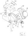
- ist eine perspektivische Ansicht einer ersten Ausführungsform eines erfindungsgemäßen Ölspiegelregulators.
- Fig. 2
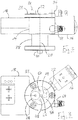
- ist eine Ansicht des Ölspiegelregulators von
Fig. 1 von unten. - Fig. 3
- ist eine Vorderansicht des Ölspiegelregulators von
Fig. 1 mit entferntem Schauglas und geschnittener Ringscheibe zur besseren Darstellung des Inneren einer Kammer des Ölspiegelregulators. - Fig. 4A
- ist eine Vorderansicht des Ölspiegelregulators von
Fig. 1 . - Fig. 4B
- ist die Schnittansicht B-B von
Fig. 4A . - Fig. 4C
- ist die Schnittansicht C-C von
Fig. 4A . - Fig. 4D
- ist eine perspektivische Ansicht des Schnitts B-B von
Fig. 4A . - Fig. 5
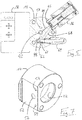
- ist eine Teilschnittansicht des Ölspiegelregulators von
Fig. 1 . - Fig. 6A
- ist eine perspektivische Ansicht einer zweiten Ausführungsform eines erfindungsgemäßen Ölspiegelregulators.
- Fig. 6B
- ist eine Seitenansicht des Ölspiegelregulators von
Fig. 6A . - Fig. 7
- ist eine perspektivische Ansicht eines Grundkörpers des Ölspiegelregulators von
Fig. 6A . - Fig. 8
- ist eine Vorderansicht einer dritten Ausführungsform eines erfindungsgemäßen Ölspiegelregulators mit entferntem Schauglas und geschnittener Ringscheibe zur besseren Darstellung des Inneren einer Kammer des Ölspiegelregulators.
- Fig. 9
- ist eine perspektivische Ansicht einer vierten Ausführungsform eines erfindungsgemäßen Ölspiegelregulators.
- Fig. 10A
- ist eine Vorderansicht einer fünften Ausführungsform eines erfindungsgemäßen Ölspiegelregulators.
- Fig. 10B
- ist die Schnittansicht B-B von
Fig. 10A . - Fig. 11
- ist eine perspektivische Ansicht einer sechsten Ausführungsform eines erfindungsgemäßen Ölspiegelregulators.
- Der Grundkörper 14 ist einstückig aus einem Metallmaterial gefertigt, und zwar mittels eines Drehverfahrens, sodass der Grundkörper 14, eine rotationssymmetrische, genauer gesagt kreiszylindrische, Grundform aufweist. Der Grundkörper 14 definiert entsprechend eine Symmetrieachse 20, welche mit der Längsmittelachse der kreiszylindrischen Grundform zusammenfällt. Die Symmetrieachse 20 definiert eine axiale Richtung, wohingegen rechtwinklig hierzu orientierte Richtungen als radial bezeichnet werden.
- Der Grundkörper 14 bildet in seinem Inneren eine Kammer 22 aus, die zur Aufnahme von Öl dient. Zur Ermittlung des Ölstands in der Kammer 22 ist ein Schwimmer 24 in der Kammer 22 angeordnet. Der Schwimmer 24 ist durch einen Auftriebskörper gebildet, welcher an dem einen Ende eines Arms 26 sitzt, dessen anderes Ende an einem Drehkörper 28 angebracht ist, welcher um eine zu Symmetrieachse 20 parallel versetzte Drehachse 30 in der Kammer 22 drehbar gelagert ist. Um die Lage des Schwimmers 24 und somit den Ölstand in der Kammer 22 optisch auslesen zu können, ist eine vordere Stirnseite des Grundkörpers 14 durch ein Schauglas 32 verschlossen, welches in einer Ringscheibe 34 sitzt, die mittels dreier Schrauben 36 an den Grundkörper 14 angeschraubt ist.
- An seiner dem Schauglas 32 abgewandten Rückseite bildet der Grundkörper 14 einen Flanschabschnitt 38 aus, welcher eine Befestigung des Ölspiegelregulators beispielsweise an einem Verdichter einer Kältemaschine oder Wärmepumpe ermöglicht. Der Flanschabschnitt 38 ist hohlzylindrisch ausgebildet und umgibt einen sich koaxial mit der Symmetrieachse 20 erstreckenden Rohrabschnitt 40, der in seinem Inneren einen Ölauslasskanal 42 definiert, welcher dazu dient, dem Verdichter Öl zuzuführen.
- Der Rohrabschnitt 40 ist von einem Ringspalt 44 umgeben, der an einen Ölsumpf des Verdichters anschließbar ist. Der Ölauslasskanal 42 und der Ringspalt 44 sind durch eine Wand 46 des Grundkörpers 14 von der Kammer 22 getrennt. Allerdings sind in der Wand 46 eine untere Öffnung 48 und eine obere Öffnung 50 ausgebildet, im dargestellten Ausführungsbeispiel in Form von gleichgroßen kreisrunden Bohrungen. Wie erwähnt beziehen sich die Bezeichnungen "oben" und "unten" in diesem Kontext auf den Einbauzustand des Ölspiegelregulators. Über die Bohrungen 48, 50 kommuniziert die Kammer 22 mit dem Ringspalt 44. Dabei dient insbesondere die untere Öffnung 48 für einen Ölaustausch zwischen der Kammer 22 und dem Ringspalt 44, während die obere Öffnung 50 üblicherweise für eine Entgasung der Kammer 22 sorgt.
- Das Elektronikmodul 18 ist an einer Außenseite des Grundkörpers 14 angebracht. Der Grundkörper 14 ist hierfür mit einer Flachfräsung versehen, welche eine ebene Fläche 52 definiert, die sich parallel zur Symmetrieachse 20 erstreckt und im eingebauten Zustand des Ölspiegelregulators im Wesentlichen vertikal orientiert ist. In der ebenen Fläche 52 sind geeignete Befestigungspunkte 54 zur Befestigung des Elektronikmoduls 18 vorgesehen. Auf der Höhe der Drehachse 30 des Drehkörpers 28 ist außerdem eine Tasche 56 für einen Hallsensor 58 des Elektronikmoduls18 ausgebildet. Bei der Montage des Elektronikmoduls 18 an dem Grundkörper 14 braucht der Hallsensor 58 des Elektronikmoduls18 also lediglich in die Tasche 56 des Grundkörpers 14 eingesetzt zu werden, um sicherzustellen, dass der Hallsensor 58 bezogen auf den Drehkörper 28 korrekt positioniert ist. Mithilfe des Hallsensors 58 kann sodann die Rotationslage des Drehkörpers 28 und somit die Lage des Schwimmers 24 in der Kammer 22, d.h. also letztlich der Ölstand der Kammer 22 und somit im Verdichter elektrisch erfasst werden.
- Detektiert das Elektronikmodul 18, dass der Ölstand in der Kammer 22 und somit im Ölsumpf des Verdichters unter einen vorbestimmten Schwellenwert sinkt, so kann das Elektronikmodul 18 das Magnetventil 16 ansteuern, um dem Verdichter Öl zuzuführen.
- Zu diesem Zweck ist ein Öleinlasskanal 60 in dem Grundkörper 14 ausgebildet, welcher durch eine von der dem Elektronikmodul 18 gegenüberliegenden Seite her kreissehnenartig in den Grundkörper 14 gesetzte Bohrung 62 und einen darin eingeschraubten Anschlussstutzen 64 definiert ist. Wie
Fig. 4 und5 zu entnehmen ist, verläuft der Öleinlasskanal 60 hinter der Kammer 22 und unterhalb der Symmetrieachse 20. - Das Magnetventil 16 sitzt in einer dem Elektronikmodul 18 gegenüberliegend und oberhalb des Öleinlasskanals 60 angeordneten, radial in den Grundkörper 14 eingebrachten Ventilaufnahme 66, sodass das Magnetventil 16 insgesamt radial zur Symmetrieachse 20 ausgerichtet ist. Im dargestellten Ausführungsbeispiel sind die Ventilaufnahme 66 und das Magnetventil 16 unter einem Winkel von etwa 45° zu dem Öleinlasskanal 60 orientiert.
- Ausgehend von der Ventilaufnahme 66 ist eine kreissehnenartig verlaufende Bohrung gesetzt, welche einen den Öleinlasskanal 60 mit dem Magnetventil 16 verbindenden ersten Kanalabschnitt 68 bildet. Dazu beabstandet ist ausgehend von der Ventilaufnahme 66 eine radial verlaufende zweite Bohrung gesetzt, welche einen zweiten Kanalabschnitt 70 bildet, der das Magnetventil 16 mit dem Ölauslasskanal 42 verbindet.
- Wird das Magnetventil 16 durch das Elektronikmodul 18 geöffnet, so kann Öl durch den Öleinlasskanal 60, den ersten Kanalabschnitt 68, das Magnetventil 16, den zweiten Kanalabschnitt 70 und schließlich den Ölauslasskanal 42 in den Verdichter strömen.
- Grundsätzlich ist es denkbar, dass der erste Kanalabschnitt 68 und der zweite Kanalabschnitt 70 in einer zur Symmetrieachse 20 rechtwinkligen Ebene liegen. Im vorliegenden Ausführungsbeispiel sind das Magnetventil 16 und der Öleinlasskanal 60 in axialer Richtung gesehen jedoch leicht versetzt zueinander angeordnet. Konkret liegt der Öleinlasskanal 60 zur Vermeidung einer Kollision mit der Kammer 22 in axialer Richtung gesehen etwas hinter dem Magnetventil 16. Insofern liegt bei der dargestellten Ausführungsform lediglich der zweite Kanalabschnitt 70 in einer zur Symmetrieachse 20 rechtwinkligen Ebene, während der erste Kanalabschnitt 68 zu dieser Ebene geringfügig geneigt ist.
- Wie bereits erwähnt bildet der Flanschabschnitt 38 bei der voranstehend beschriebenen ersten Ausführungsform einen integralen Bestandteil des Grundkörpers 14. Alternativ ist es aber auch möglich, den Flanschabschnitt 38 als ein von dem Grundkörper 14 separates Bauteil herzustellen und anschließend an dem Grundkörper 14 anzubringen, insbesondere anzuschrauben. Eine entsprechend ausgebildete zweite Ausführungsform, die sich ansonsten weiter nicht von der voranstehend beschriebenen ersten Ausführungsform unterscheidet, ist in
Fig. 6A und 6B gezeigt. Der dazugehörige Grundkörper 14 ist inFig. 7 dargestellt. Besonders gut erkennbar ist hierin die kreiszylindrische Grundform des Grundkörpers 14 sowie die durch Flachfräsen der Mantelfläche erzeugte ebene Fläche 52 für die Anbringung des Elektronikmoduls 18 mit den zur Fixierung des Elektronikmoduls 18 vorgesehenen Befestigungspunkten 54 sowie der Tasche 56 für den Hallsensor 58. - Eine dritte Ausführungsform des Ölspiegelregulators ist in
Fig. 8 gezeigt. Diese dritte Ausführungsform unterscheidet sich von der inFig. 6A und 6B gezeigten zweiten Ausführungsform lediglich in der Gestalt der zur Entgasung der Kammer 22 vorgesehenen oberen Öffnung 50 in der Wand 46 des Grundkörpers 14, während die für den Ölaustausch zwischen dem Ringsspalt 44 und der Kammer 22 vorgesehene untere Öffnung 48 nämlich wie zuvor durch eine kreisförmige Bohrung gebildet ist, weist die zur Entgasung dienende obere Öffnung 50 eine größere Querschnittsfläche als die untere Öffnung 48 auf. Konkret ist die obere Öffnung 50 hier in Form eines um die Symmetrieachse 20 herumgekrümmten Langlochs ausgebildet, was der oberen Öffnung 50 eine nierenförmige Gestalt verleiht. Die im Vergleich zur unteren Öffnung 48 größere Querschnittsfläche der oberen Öffnung 50 trägt zu einer effizienteren Entgasung der Kammer und reduzierten Gefahr von Schaumbildung in der Kammer 22 bei. - In
Fig. 9 ist eine vierte Ausführungsform eines Ölspiegelregulators dargestellt, welche sich von der inFig. 6A und 6B gezeigten zweiten Ausführungsform lediglich darin unterscheidet, dass der Grundkörper 14 auch an seiner Oberseite eine, insbesondere durch Flachfräsen erzeugte, ebene Fläche 72 aufweist, welche zumindest annähernd rechtwinklig zu der vertikalen ebenen Fläche 52 orientiert ist, die zur Befestigung des Elektronikmoduls 18 dient. Im Bereich der oberen ebenen Fläche 72 ist eine Wasserwaage 74, hier in Form einer Rundlibelle, in den Grundkörper 14, eingelassen. Die Wasserwaage 74 dient als Montagehilfe und erleichtert insbesondere eine korrekte Ausrichtung des Ölspiegelregulators, welche letztlich für eine zuverlässige Ölspiegelregulator unerlässlich ist. - Damit die Wasserwaage 74 zumindest annähernd bündig mit der ebenen Fläche 72 abschließt, ist eine entsprechende Vertiefung 76 in dem Grundkörper 14 vorgesehen. Im vorliegenden Ausführungsbeispiel ist die Wasserwaage 74 in die Vertiefung 76 eingeschraubt. Es ist aber auch denkbar, die Wasserwaage 74 in die Vertiefung 76 einzupressen oder einzukleben. Selbstverständlich kann die Wasserwaage 74 auch direkt auf der ebenen Fläche 72 angebracht werden, beispielsweise auf diese aufgeklebt werden. Des Weiteren ist eine lösbare Verbindung von Wasserwaage 74 und Grundkörper 14 vorstellbar, was es erlauben würde, die Wasserwaage 74 nach dem Einbau des Ölspiegelregulators abzunehmen und für die Justierung eines anderen Ölspiegelregulators zu verwenden.
- In
Fig. 10A und 10B ist eine fünfte Ausführungsform eines Ölspiegelregulators dargestellt, welche sich von der inFig. 6A und 6B gezeigten zweiten Ausführungsform lediglich in der Ausbildung des Elektronikmoduls 18 unterscheidet. Während das Elektronikmodul 18 der zweiten Ausführungsform nämlich ein aus zwei Gehäusehälften 78a, 78b zusammengesetztes Gehäuse 78 aufweist, in welchem die vorhandenen Elektronikbauteile untergebracht sind, handelt es sich bei dem Elektronikmodul 18 der fünften Ausführungsform um eine vergossene Elektronik, d.h. eine Leiterplatte 80 und darauf sitzende Elektronikbauteile 82 sind mit einem Harz umgossen, wodurch auf ein Gehäuse verzichtet werden kann. - In
Fig. 10B ist auch der Hallsensor 58 zu erkennen, der an der dem Grundkörper 14 zugewandten Außenseite des Elektronikmoduls 18 sitzt und in der Tasche 56 des Grundkörpers 14 aufgenommen ist. - In
Fig. 11 ist eine sechste Ausführungsform eines Ölspiegelregulators dargestellt, welche sich von der inFig. 6A und 6B gezeigten zweiten Ausführungsform darin unterscheidet, dass das Magnetventil 16 nicht schräg, d.h. unter einem Winkel von 45°, an dem Grundkörper 14 angebracht ist, sondern bezogen auf die Einbaulage des Ölspiegelregulators vertikal ausgerichtet ist, gewissermaßen also oben auf dem Grundkörper 14 sitzt und einen rechten Winkel mit dem Öleinlasskanal 60 bildet. Im weiteren Unterschied zur zweiten Ausführungsform verläuft der Öleinlasskanal 60 der inFig. 11 dargestellten sechsten Ausführungsform nicht unterhalb sondern oberhalb der Symmetrieachse 20, wie sich aus der Lage des Anschlussstutzens 64 unschwer erkennen lässt. Der sich von dem Magnetventil 16 zu dem Öleinlasskanal 60 erstreckende erste Kanalabschnitt 68 fällt bei dieser sechsten Ausführungsform also deutlich kürzer aus als bei der zweiten Ausführungsform, wohingegen sich der zweite Kanalabschnitt 70 wiederum radial von dem Magnetventil 16 zu dem Ölauslasskanal 42 hin erstreckt. - Abschließend sei darauf hingewiesen, dass die Ausbildung des Elektronikmoduls 18 grundsätzlich unabhängig von der Lage des Magnetventils 16 und auch unabhängig davon ist, ob der Grundkörper 14 und der Flanschabschnitt 38 einstückig ausgebildet oder separate Bauteile sind. Insbesondere können auch die erste bis vierte und sechs Ausführungsform mit einem vergossenen Elektronikmodul 18, wie es in
Fig. 10A und 10B gezeigt ist, ausgerüstet sein. Entsprechend kann mit Ausnahme der sechsten Ausführungsform, bei welcher das Magnetventil 16 oben auf dem Grundkörper 14 sitzt, jede der ersten bis dritten und fünften Ausführungsformen mit einer Wasserwaage 74 versehen sein. Schließlich kann ähnlich wie bei der vierten Ausführungsform jede der ersten bis dritten, fünften und sechsten Ausführungsformen eine obere Öffnung 50 zur Entgasung der Kammer 22 aufweisen, deren Querschnittsfläche größer ist als die der unteren Öffnung 48. -
- 14
- Grundkörper
- 16
- Magnetventil
- 18
- Elektronikmodul
- 20
- Symmetrieachse
- 22
- Kammer
- 24
- Schwimmer
- 26
- Arm
- 28
- Drehkörper
- 30
- Drehachse
- 32
- Schauglas
- 34
- Ringscheibe
- 36
- Schraube
- 38
- Flanschabschnitt
- 40
- Rohrabschnitt
- 42
- Ölauslasskanal
- 44
- Ringspalt
- 46
- Wand
- 48
- untere Öffnung
- 50
- obere Öffnung
- 52
- ebene Fläche
- 54
- Befestigungspunkt
- 56
- Tasche
- 58
- Hallsensor
- 60
- Öleinlasskanal
- 62
- Bohrung
- 64
- Anschlussstutzen
- 66
- Ventilaufnahme
- 68
- erster Kanalabschnitt
- 70
- zweiter Kanalabschnitt
- 72
- ebene Fläche
- 74
- Wasserwaage
- 76
- Vertiefung
- 78
- Gehäuse
- 78a
- Gehäusehälfte
- 78b
- Gehäusehälfte
- 80
- elektronisches Bauteil
- 82
- Leiterplatte
- 84
- Harz
Claims (15)
- Ölspiegelregulator miteinem Grundkörper (14),einer in dem Grundkörper (14) ausgebildeten, durch ein Schauglas (32) begrenzten und zur Aufnahme von Öl vorgesehenen Kammer (22), in welcher ein Schwimmer (24) angeordnet ist,einem Hallsensor (58) zur Erfassung der Lage des Schwimmers (24) innerhalb der Kammer (22),einem in dem Grundkörper (14) ausgebildeten Öleinlasskanal (60),einem in dem Grundkörper (14) ausgebildeten und mit der Kammer (22) kommunizierenden Ölauslasskanal (42),einem an dem Grundkörper (14) angebrachten und zwischen den Öleinlasskanal (60) und den Ölauslasskanal (42) geschalteten Magnetventil (16) zum Steuern eines Ölflusses von dem Öleinlasskanal (60) zu dem Ölauslasskanal (42), undeinem in dem Grundkörper (14) ausgebildeten Anbindungskanal (44) zum Anbinden der Kammer (22) an einen Ölsumpf eines Verdichters, wobei der Anbindungskanal (44) über eine untere Öffnung (48) und eine obere Öffnung (50) mit der Kammer (22) kommuniziert,dadurch gekennzeichnet,dass die obere Öffnung (50) eine größere Querschnittsfläche aufweist als die untere Öffnung (48).
- Ölspiegelregulator nach Anspruch 1,
dadurch gekennzeichnet,
dass die obere Öffnung (50) durch ein Langloch, beispielsweise ein gekrümmtes, insbesondere nierenförmig gekrümmtes, Langloch gebildet ist. - Ölspiegelregulator nach Anspruch 1,
dadurch gekennzeichnet,
dass sich die obere Öffnung (50) aus wenigstens zwei separaten Löchern zusammensetzt. - Ölspiegelregulator nach zumindest einem der vorherigen Ansprüche,
dadurch gekennzeichnet,
dass der Anbindungskanal (44) den Ölauslasskanal (42) ringförmig umgibt und/oder sich entlang einer Symmetrieachse (20) des Grundkörpers (14) erstreckt. - Ölspiegelregulator nach zumindest einem der vorherigen Ansprüche,
dadurch gekennzeichnet,
dass dem Grundkörper (14) eine bezüglich einer Symmetrieachse (20) rotationssymmetrische Grundform zugrunde liegt, insbesondere eine kreiszylindrische Grundform. - Ölspiegelregulator (42) nach zumindest einem der vorherigen Ansprüche,
dadurch gekennzeichnet,
dass sich der Ölauslasskanal (42) parallel zu einer Symmetrieachse (20) des Grundkörpers (14) und insbesondere koaxial zu dieser erstreckt. - Ölspiegelregulator nach zumindest einem der vorherigen Ansprüche,
dadurch gekennzeichnet,
dass das Magnetventil (16) radial zu einer Symmetrieachse (20) des Grundkörpers (14) ausgerichtet ist. - Ölspiegelregulator nach zumindest einem der vorherigen Ansprüche,
dadurch gekennzeichnet,
dass der Öleinlasskanal (60) und das Magnetventil (16) durch einen sich innerhalb des Grundkörpers (16) erstreckenden geraden ersten Kanalabschnitt (68) miteinander verbunden sind. - Ölspiegelregulator nach zumindest einem der vorherigen Ansprüche,
dadurch gekennzeichnet,
dass das Magnetventil (16) und der Ölauslasskanal (42) durch einen geraden zweiten Kanalabschnitt (70) miteinander verbunden sind, welcher sich radial zu einer Symmetrieachse (20) des Grundkörpers (14) in diesem erstreckt. - Ölspiegelregulator nach Anspruch 8 und 9,
dadurch gekennzeichnet,
dass der erste und zweite Kanalabschnitt (68, 70) eine Ebene aufspannen, die zumindest annähernd rechtwinklig zur Symmetrieachse (20) des Grundkörpers (14) ausgerichtet ist. - Ölspiegelregulator nach zumindest einem der vorherigen Ansprüche,
dadurch gekennzeichnet,
dass der Grundkörper (14) eine Tasche (56) für den Hallsensor (58) ausbildet. - Ölspiegelregulator nach zumindest einem der vorherigen Ansprüche,
dadurch gekennzeichnet,
dass ein, insbesondere vergossenes, Elektronikmodul (18) an dem Grundkörper (14) angebracht ist und insbesondere im Bereich einer Tasche (56) für den Hallsensor (58) angeordnet ist. - Ölspiegelregulator nach Anspruch 11 oder 12,
dadurch gekennzeichnet,
dass der Grundkörper (14) an seiner Außenseite eine sich parallel zu einer Symmetrieachse (20) erstreckende ebene Fläche (52) ausbildet, in welcher die Tasche (56) für den Hallsensor (58) und/oder das Elektronikmodul (18) angeordnet sind/ist. - Ölspiegelregulator nach zumindest einem der vorherigen Ansprüche,
dadurch gekennzeichnet,
dass eine Wasserwaage (74), beispielsweise mit Rundlibelle, an dem Grundkörper (14) angebracht ist, insbesondere an einer Oberseite des Grundkörpers (14). - Ölspiegelregulator nach zumindest einem der vorherigen Ansprüche,
dadurch gekennzeichnet,
dass der Grundkörper (14) einen Flansch und/oder Adapter (38) zur Anbringung des Ölspiegelregulators an einem Verdichter ausbildet, oder dass ein Flansch und/oder Adapter (38) zur Anbringung des Ölspiegelregulators an einem Verdichter an dem Grundkörper (14) angebracht, z.B. angeschraubt, ist.
Priority Applications (1)
| Application Number | Priority Date | Filing Date | Title |
|---|---|---|---|
| EP20165398.7A EP3885716B1 (de) | 2020-03-24 | 2020-03-24 | Ölspiegelregulator |
Applications Claiming Priority (1)
| Application Number | Priority Date | Filing Date | Title |
|---|---|---|---|
| EP20165398.7A EP3885716B1 (de) | 2020-03-24 | 2020-03-24 | Ölspiegelregulator |
Publications (2)
| Publication Number | Publication Date |
|---|---|
| EP3885716A1 true EP3885716A1 (de) | 2021-09-29 |
| EP3885716B1 EP3885716B1 (de) | 2022-09-07 |
Family
ID=69960498
Family Applications (1)
| Application Number | Title | Priority Date | Filing Date |
|---|---|---|---|
| EP20165398.7A Revoked EP3885716B1 (de) | 2020-03-24 | 2020-03-24 | Ölspiegelregulator |
Country Status (1)
| Country | Link |
|---|---|
| EP (1) | EP3885716B1 (de) |
Citations (6)
| Publication number | Priority date | Publication date | Assignee | Title |
|---|---|---|---|---|
| JPS6091218A (ja) * | 1983-10-26 | 1985-05-22 | Mitsui Toatsu Chem Inc | 内筒式液面計 |
| US5026954A (en) * | 1989-10-16 | 1991-06-25 | Hi-Stat Manufacturing Co., Inc. | Liquid level sensing switch assembly |
| US5911289A (en) * | 1994-06-17 | 1999-06-15 | Waller; Clive Gregory | Oil level control apparatus |
| US6125642A (en) * | 1999-07-13 | 2000-10-03 | Sporlan Valve Company | Oil level control system |
| DE102007012917A1 (de) * | 2007-03-19 | 2008-09-25 | Robert Bosch Gmbh | Vorrichtung und Verfahren zur Füllstandsmessung eines Fahrzeugtanks |
| WO2017098346A1 (en) * | 2015-12-07 | 2017-06-15 | Igloo Refrigerazione S.R.L. | Oil level signalling device for compressor and oil management apparatus, with removable detection and control unit |
Family Cites Families (4)
| Publication number | Priority date | Publication date | Assignee | Title |
|---|---|---|---|---|
| GB190522383A (en) | 1905-11-02 | 1906-04-19 | George Barker | A New or Improved Liquid Level Regulator. |
| US3134332A (en) | 1962-03-19 | 1964-05-26 | Robert E Nelson | Pump and liquid level regulator |
| US5542499A (en) | 1995-01-11 | 1996-08-06 | Ac&R Components, Inc. | Electromechanical oil level regulator |
| AUPO205096A0 (en) | 1996-09-02 | 1996-09-26 | Refrigerant Monitoring Systems Pty Ltd | Time delayed fluid level monitoring device |
-
2020
- 2020-03-24 EP EP20165398.7A patent/EP3885716B1/de not_active Revoked
Patent Citations (6)
| Publication number | Priority date | Publication date | Assignee | Title |
|---|---|---|---|---|
| JPS6091218A (ja) * | 1983-10-26 | 1985-05-22 | Mitsui Toatsu Chem Inc | 内筒式液面計 |
| US5026954A (en) * | 1989-10-16 | 1991-06-25 | Hi-Stat Manufacturing Co., Inc. | Liquid level sensing switch assembly |
| US5911289A (en) * | 1994-06-17 | 1999-06-15 | Waller; Clive Gregory | Oil level control apparatus |
| US6125642A (en) * | 1999-07-13 | 2000-10-03 | Sporlan Valve Company | Oil level control system |
| DE102007012917A1 (de) * | 2007-03-19 | 2008-09-25 | Robert Bosch Gmbh | Vorrichtung und Verfahren zur Füllstandsmessung eines Fahrzeugtanks |
| WO2017098346A1 (en) * | 2015-12-07 | 2017-06-15 | Igloo Refrigerazione S.R.L. | Oil level signalling device for compressor and oil management apparatus, with removable detection and control unit |
Also Published As
| Publication number | Publication date |
|---|---|
| EP3885716B1 (de) | 2022-09-07 |
Similar Documents
| Publication | Publication Date | Title |
|---|---|---|
| DE69902371T2 (de) | Schneidwerkzeug mit düse | |
| DE102009048010B3 (de) | Werkzeuginterface | |
| DE102011001446B4 (de) | Schnellwechseladapter für eine Lochsäge | |
| DE60308291T2 (de) | Tiefbohrwerkzeug | |
| EP0625395B1 (de) | Bohrwerkzeug für metallische Werkstoffe | |
| WO2003070408A1 (de) | Rundlaufschneidwerkzeug mit auswechselbarem schneideinsatz | |
| EP1100642A1 (de) | Bohrwerkzeug mit einem gegen lösen gesicherten, austauschbaren schneideinsatz | |
| EP2032295A1 (de) | Trennstelle zwischen zwei teilelementen eines drehenden werkzeugsystems | |
| CH663562A5 (de) | Kupplungsvorrichtung fuer modulare werkzeugsysteme. | |
| EP1474258A1 (de) | Maschinenreibahle | |
| EP0450026A1 (de) | Spiralbohrer | |
| DE69207464T2 (de) | Schneidwerkzeug | |
| EP3885715B1 (de) | Ölspiegelregulator | |
| DE112006002010B4 (de) | Vorrichtung zur Kühlmitteleinspeisung in einen Schaft eines Rundlaufwerkzeugs sowie ein Rundlaufwerkzeug, insbesondere Bohrer | |
| EP2535127A1 (de) | Werkzeug mit Feineinstellung | |
| EP3885716B1 (de) | Ölspiegelregulator | |
| DD290156A5 (de) | Bohrvorrichtung zur herstellung von bohrloechern mit hinterschneidung | |
| EP1287264A1 (de) | Hydraulisches gerät | |
| DE102004001970A1 (de) | Maschinenwerkzeug sowie Grundkörper und Schneidplatte für ein Maschinenwerkzeug | |
| EP1819470B1 (de) | Handwerkzeugmaschine, insbesondere bohrmaschine oder schrauber | |
| DE102008006233A1 (de) | Injektionsstutzen | |
| DE102008006234A1 (de) | Injektionskopf | |
| EP1609550A1 (de) | Verbindungssystem und Werkzeugteil | |
| EP1738849B1 (de) | Schaftfräser | |
| EP0258660A1 (de) | Einlippen-Vollbohrer |
Legal Events
| Date | Code | Title | Description |
|---|---|---|---|
| PUAI | Public reference made under article 153(3) epc to a published international application that has entered the european phase |
Free format text: ORIGINAL CODE: 0009012 |
|
| STAA | Information on the status of an ep patent application or granted ep patent |
Free format text: STATUS: REQUEST FOR EXAMINATION WAS MADE |
|
| 17P | Request for examination filed |
Effective date: 20210211 |
|
| AK | Designated contracting states |
Kind code of ref document: A1 Designated state(s): AL AT BE BG CH CY CZ DE DK EE ES FI FR GB GR HR HU IE IS IT LI LT LU LV MC MK MT NL NO PL PT RO RS SE SI SK SM TR |
|
| RIN1 | Information on inventor provided before grant (corrected) |
Inventor name: QUINN, MATTHEW Inventor name: FUHRMANN, CHRISTIAN Inventor name: NEPOVIM, RADOVAN |
|
| RIC1 | Information provided on ipc code assigned before grant |
Ipc: G05D 9/00 20060101ALN20220331BHEP Ipc: F25B 49/00 20060101ALN20220331BHEP Ipc: F25B 31/00 20060101ALN20220331BHEP Ipc: F16N 19/00 20060101ALN20220331BHEP Ipc: F01M 11/12 20060101ALN20220331BHEP Ipc: F01M 11/06 20060101ALN20220331BHEP Ipc: G01F 23/80 20220101ALI20220331BHEP Ipc: G01F 23/38 20060101ALI20220331BHEP Ipc: G01F 23/02 20060101ALI20220331BHEP Ipc: G01F 23/00 20060101AFI20220331BHEP |
|
| GRAP | Despatch of communication of intention to grant a patent |
Free format text: ORIGINAL CODE: EPIDOSNIGR1 |
|
| STAA | Information on the status of an ep patent application or granted ep patent |
Free format text: STATUS: GRANT OF PATENT IS INTENDED |
|
| RIC1 | Information provided on ipc code assigned before grant |
Ipc: G05D 9/00 20060101ALN20220502BHEP Ipc: F25B 49/00 20060101ALN20220502BHEP Ipc: F25B 31/00 20060101ALN20220502BHEP Ipc: F16N 19/00 20060101ALN20220502BHEP Ipc: F01M 11/12 20060101ALN20220502BHEP Ipc: F01M 11/06 20060101ALN20220502BHEP Ipc: G01F 23/80 20220101ALI20220502BHEP Ipc: G01F 23/38 20060101ALI20220502BHEP Ipc: G01F 23/02 20060101ALI20220502BHEP Ipc: G01F 23/00 20060101AFI20220502BHEP |
|
| INTG | Intention to grant announced |
Effective date: 20220518 |
|
| GRAS | Grant fee paid |
Free format text: ORIGINAL CODE: EPIDOSNIGR3 |
|
| GRAA | (expected) grant |
Free format text: ORIGINAL CODE: 0009210 |
|
| STAA | Information on the status of an ep patent application or granted ep patent |
Free format text: STATUS: THE PATENT HAS BEEN GRANTED |
|
| AK | Designated contracting states |
Kind code of ref document: B1 Designated state(s): AL AT BE BG CH CY CZ DE DK EE ES FI FR GB GR HR HU IE IS IT LI LT LU LV MC MK MT NL NO PL PT RO RS SE SI SK SM TR |
|
| REG | Reference to a national code |
Ref country code: GB Ref legal event code: FG4D Free format text: NOT ENGLISH |
|
| RIN1 | Information on inventor provided before grant (corrected) |
Inventor name: QUINN, MATTHEW Inventor name: FUHRMANN, CHRISTIAN Inventor name: NEPOVIM, RADOVAN |
|
| REG | Reference to a national code |
Ref country code: CH Ref legal event code: EP Ref country code: AT Ref legal event code: REF Ref document number: 1517412 Country of ref document: AT Kind code of ref document: T Effective date: 20220915 |
|
| REG | Reference to a national code |
Ref country code: DE Ref legal event code: R096 Ref document number: 502020001635 Country of ref document: DE |
|
| REG | Reference to a national code |
Ref country code: IE Ref legal event code: FG4D Free format text: LANGUAGE OF EP DOCUMENT: GERMAN |
|
| REG | Reference to a national code |
Ref country code: LT Ref legal event code: MG9D |
|
| REG | Reference to a national code |
Ref country code: NL Ref legal event code: MP Effective date: 20220907 |
|
| PG25 | Lapsed in a contracting state [announced via postgrant information from national office to epo] |
Ref country code: SE Free format text: LAPSE BECAUSE OF FAILURE TO SUBMIT A TRANSLATION OF THE DESCRIPTION OR TO PAY THE FEE WITHIN THE PRESCRIBED TIME-LIMIT Effective date: 20220907 Ref country code: RS Free format text: LAPSE BECAUSE OF FAILURE TO SUBMIT A TRANSLATION OF THE DESCRIPTION OR TO PAY THE FEE WITHIN THE PRESCRIBED TIME-LIMIT Effective date: 20220907 Ref country code: NO Free format text: LAPSE BECAUSE OF FAILURE TO SUBMIT A TRANSLATION OF THE DESCRIPTION OR TO PAY THE FEE WITHIN THE PRESCRIBED TIME-LIMIT Effective date: 20221207 Ref country code: LV Free format text: LAPSE BECAUSE OF FAILURE TO SUBMIT A TRANSLATION OF THE DESCRIPTION OR TO PAY THE FEE WITHIN THE PRESCRIBED TIME-LIMIT Effective date: 20220907 Ref country code: LT Free format text: LAPSE BECAUSE OF FAILURE TO SUBMIT A TRANSLATION OF THE DESCRIPTION OR TO PAY THE FEE WITHIN THE PRESCRIBED TIME-LIMIT Effective date: 20220907 Ref country code: FI Free format text: LAPSE BECAUSE OF FAILURE TO SUBMIT A TRANSLATION OF THE DESCRIPTION OR TO PAY THE FEE WITHIN THE PRESCRIBED TIME-LIMIT Effective date: 20220907 |
|
| PG25 | Lapsed in a contracting state [announced via postgrant information from national office to epo] |
Ref country code: HR Free format text: LAPSE BECAUSE OF FAILURE TO SUBMIT A TRANSLATION OF THE DESCRIPTION OR TO PAY THE FEE WITHIN THE PRESCRIBED TIME-LIMIT Effective date: 20220907 Ref country code: GR Free format text: LAPSE BECAUSE OF FAILURE TO SUBMIT A TRANSLATION OF THE DESCRIPTION OR TO PAY THE FEE WITHIN THE PRESCRIBED TIME-LIMIT Effective date: 20221208 |
|
| PG25 | Lapsed in a contracting state [announced via postgrant information from national office to epo] |
Ref country code: SM Free format text: LAPSE BECAUSE OF FAILURE TO SUBMIT A TRANSLATION OF THE DESCRIPTION OR TO PAY THE FEE WITHIN THE PRESCRIBED TIME-LIMIT Effective date: 20220907 Ref country code: RO Free format text: LAPSE BECAUSE OF FAILURE TO SUBMIT A TRANSLATION OF THE DESCRIPTION OR TO PAY THE FEE WITHIN THE PRESCRIBED TIME-LIMIT Effective date: 20220907 Ref country code: PT Free format text: LAPSE BECAUSE OF FAILURE TO SUBMIT A TRANSLATION OF THE DESCRIPTION OR TO PAY THE FEE WITHIN THE PRESCRIBED TIME-LIMIT Effective date: 20230109 Ref country code: ES Free format text: LAPSE BECAUSE OF FAILURE TO SUBMIT A TRANSLATION OF THE DESCRIPTION OR TO PAY THE FEE WITHIN THE PRESCRIBED TIME-LIMIT Effective date: 20220907 Ref country code: CZ Free format text: LAPSE BECAUSE OF FAILURE TO SUBMIT A TRANSLATION OF THE DESCRIPTION OR TO PAY THE FEE WITHIN THE PRESCRIBED TIME-LIMIT Effective date: 20220907 |
|
| PG25 | Lapsed in a contracting state [announced via postgrant information from national office to epo] |
Ref country code: SK Free format text: LAPSE BECAUSE OF FAILURE TO SUBMIT A TRANSLATION OF THE DESCRIPTION OR TO PAY THE FEE WITHIN THE PRESCRIBED TIME-LIMIT Effective date: 20220907 Ref country code: PL Free format text: LAPSE BECAUSE OF FAILURE TO SUBMIT A TRANSLATION OF THE DESCRIPTION OR TO PAY THE FEE WITHIN THE PRESCRIBED TIME-LIMIT Effective date: 20220907 Ref country code: IS Free format text: LAPSE BECAUSE OF FAILURE TO SUBMIT A TRANSLATION OF THE DESCRIPTION OR TO PAY THE FEE WITHIN THE PRESCRIBED TIME-LIMIT Effective date: 20230107 Ref country code: EE Free format text: LAPSE BECAUSE OF FAILURE TO SUBMIT A TRANSLATION OF THE DESCRIPTION OR TO PAY THE FEE WITHIN THE PRESCRIBED TIME-LIMIT Effective date: 20220907 |
|
| REG | Reference to a national code |
Ref country code: DE Ref legal event code: R026 Ref document number: 502020001635 Country of ref document: DE |
|
| PLBI | Opposition filed |
Free format text: ORIGINAL CODE: 0009260 |
|
| PLAB | Opposition data, opponent's data or that of the opponent's representative modified |
Free format text: ORIGINAL CODE: 0009299OPPO |
|
| PLAX | Notice of opposition and request to file observation + time limit sent |
Free format text: ORIGINAL CODE: EPIDOSNOBS2 |
|
| PG25 | Lapsed in a contracting state [announced via postgrant information from national office to epo] |
Ref country code: NL Free format text: LAPSE BECAUSE OF FAILURE TO SUBMIT A TRANSLATION OF THE DESCRIPTION OR TO PAY THE FEE WITHIN THE PRESCRIBED TIME-LIMIT Effective date: 20220907 Ref country code: AL Free format text: LAPSE BECAUSE OF FAILURE TO SUBMIT A TRANSLATION OF THE DESCRIPTION OR TO PAY THE FEE WITHIN THE PRESCRIBED TIME-LIMIT Effective date: 20220907 |
|
| 26 | Opposition filed |
Opponent name: BITZER KUEHLMASCHINENBAU GMBH Effective date: 20230607 Opponent name: DEKA CONTROLS GMBH Effective date: 20230606 |
|
| R26 | Opposition filed (corrected) |
Opponent name: BITZER KUEHLMASCHINENBAU GMBH Effective date: 20230607 |
|
| PG25 | Lapsed in a contracting state [announced via postgrant information from national office to epo] |
Ref country code: DK Free format text: LAPSE BECAUSE OF FAILURE TO SUBMIT A TRANSLATION OF THE DESCRIPTION OR TO PAY THE FEE WITHIN THE PRESCRIBED TIME-LIMIT Effective date: 20220907 |
|
| PG25 | Lapsed in a contracting state [announced via postgrant information from national office to epo] |
Ref country code: SI Free format text: LAPSE BECAUSE OF FAILURE TO SUBMIT A TRANSLATION OF THE DESCRIPTION OR TO PAY THE FEE WITHIN THE PRESCRIBED TIME-LIMIT Effective date: 20220907 |
|
| PLBB | Reply of patent proprietor to notice(s) of opposition received |
Free format text: ORIGINAL CODE: EPIDOSNOBS3 |
|
| PG25 | Lapsed in a contracting state [announced via postgrant information from national office to epo] |
Ref country code: MC Free format text: LAPSE BECAUSE OF FAILURE TO SUBMIT A TRANSLATION OF THE DESCRIPTION OR TO PAY THE FEE WITHIN THE PRESCRIBED TIME-LIMIT Effective date: 20220907 |
|
| REG | Reference to a national code |
Ref country code: CH Ref legal event code: PL |
|
| REG | Reference to a national code |
Ref country code: BE Ref legal event code: MM Effective date: 20230331 |
|
| PG25 | Lapsed in a contracting state [announced via postgrant information from national office to epo] |
Ref country code: LU Free format text: LAPSE BECAUSE OF NON-PAYMENT OF DUE FEES Effective date: 20230324 |
|
| REG | Reference to a national code |
Ref country code: IE Ref legal event code: MM4A |
|
| PG25 | Lapsed in a contracting state [announced via postgrant information from national office to epo] |
Ref country code: LI Free format text: LAPSE BECAUSE OF NON-PAYMENT OF DUE FEES Effective date: 20230331 Ref country code: CH Free format text: LAPSE BECAUSE OF NON-PAYMENT OF DUE FEES Effective date: 20230331 Ref country code: IE Free format text: LAPSE BECAUSE OF NON-PAYMENT OF DUE FEES Effective date: 20230324 |
|
| PG25 | Lapsed in a contracting state [announced via postgrant information from national office to epo] |
Ref country code: BE Free format text: LAPSE BECAUSE OF NON-PAYMENT OF DUE FEES Effective date: 20230331 |
|
| PGFP | Annual fee paid to national office [announced via postgrant information from national office to epo] |
Ref country code: DE Payment date: 20240220 Year of fee payment: 5 |
|
| PG25 | Lapsed in a contracting state [announced via postgrant information from national office to epo] |
Ref country code: IT Free format text: LAPSE BECAUSE OF FAILURE TO SUBMIT A TRANSLATION OF THE DESCRIPTION OR TO PAY THE FEE WITHIN THE PRESCRIBED TIME-LIMIT Effective date: 20220907 |
|
| RDAF | Communication despatched that patent is revoked |
Free format text: ORIGINAL CODE: EPIDOSNREV1 |
|
| PG25 | Lapsed in a contracting state [announced via postgrant information from national office to epo] |
Ref country code: BG Free format text: LAPSE BECAUSE OF FAILURE TO SUBMIT A TRANSLATION OF THE DESCRIPTION OR TO PAY THE FEE WITHIN THE PRESCRIBED TIME-LIMIT Effective date: 20220907 |
|
| PG25 | Lapsed in a contracting state [announced via postgrant information from national office to epo] |
Ref country code: BG Free format text: LAPSE BECAUSE OF FAILURE TO SUBMIT A TRANSLATION OF THE DESCRIPTION OR TO PAY THE FEE WITHIN THE PRESCRIBED TIME-LIMIT Effective date: 20220907 |
|
| APBP | Date of receipt of notice of appeal recorded |
Free format text: ORIGINAL CODE: EPIDOSNNOA2O |
|
| APAH | Appeal reference modified |
Free format text: ORIGINAL CODE: EPIDOSCREFNO |
|
| REG | Reference to a national code |
Ref country code: DE Ref legal event code: R103 Ref document number: 502020001635 Country of ref document: DE Ref country code: DE Ref legal event code: R064 Ref document number: 502020001635 Country of ref document: DE |
|
| APBU | Appeal procedure closed |
Free format text: ORIGINAL CODE: EPIDOSNNOA9O |
|
| RDAG | Patent revoked |
Free format text: ORIGINAL CODE: 0009271 |
|
| STAA | Information on the status of an ep patent application or granted ep patent |
Free format text: STATUS: PATENT REVOKED |
|
| REG | Reference to a national code |
Ref country code: CH Ref legal event code: PL |
|
| 27W | Patent revoked |
Effective date: 20250218 |
|
| GBPR | Gb: patent revoked under art. 102 of the ep convention designating the uk as contracting state |
Effective date: 20250218 |
|
| PGFP | Annual fee paid to national office [announced via postgrant information from national office to epo] |
Ref country code: AT Payment date: 20250417 Year of fee payment: 5 |
|
| PGFP | Annual fee paid to national office [announced via postgrant information from national office to epo] |
Ref country code: FR Payment date: 20250218 Year of fee payment: 6 |
|
| PGFP | Annual fee paid to national office [announced via postgrant information from national office to epo] |
Ref country code: GB Payment date: 20250221 Year of fee payment: 6 |
|
| REG | Reference to a national code |
Ref country code: AT Ref legal event code: MA03 Ref document number: 1517412 Country of ref document: AT Kind code of ref document: T Effective date: 20250218 |
|
| PG25 | Lapsed in a contracting state [announced via postgrant information from national office to epo] |
Ref country code: CY Free format text: LAPSE BECAUSE OF FAILURE TO SUBMIT A TRANSLATION OF THE DESCRIPTION OR TO PAY THE FEE WITHIN THE PRESCRIBED TIME-LIMIT; INVALID AB INITIO Effective date: 20200324 |
|
| PG25 | Lapsed in a contracting state [announced via postgrant information from national office to epo] |
Ref country code: HU Free format text: LAPSE BECAUSE OF FAILURE TO SUBMIT A TRANSLATION OF THE DESCRIPTION OR TO PAY THE FEE WITHIN THE PRESCRIBED TIME-LIMIT; INVALID AB INITIO Effective date: 20200324 |
|
| PG25 | Lapsed in a contracting state [announced via postgrant information from national office to epo] |
Ref country code: TR Free format text: LAPSE BECAUSE OF FAILURE TO SUBMIT A TRANSLATION OF THE DESCRIPTION OR TO PAY THE FEE WITHIN THE PRESCRIBED TIME-LIMIT Effective date: 20220907 |