EP3885622B1 - Rohranschluss und rohr mit dem rohranschluss - Google Patents
Rohranschluss und rohr mit dem rohranschluss Download PDFInfo
- Publication number
- EP3885622B1 EP3885622B1 EP21175368.6A EP21175368A EP3885622B1 EP 3885622 B1 EP3885622 B1 EP 3885622B1 EP 21175368 A EP21175368 A EP 21175368A EP 3885622 B1 EP3885622 B1 EP 3885622B1
- Authority
- EP
- European Patent Office
- Prior art keywords
- tube
- axial force
- resin coating
- tube fitting
- coating layer
- Prior art date
- Legal status (The legal status is an assumption and is not a legal conclusion. Google has not performed a legal analysis and makes no representation as to the accuracy of the status listed.)
- Active
Links
- 238000012360 testing method Methods 0.000 claims description 112
- 239000011347 resin Substances 0.000 claims description 88
- 229920005989 resin Polymers 0.000 claims description 88
- 239000011247 coating layer Substances 0.000 claims description 81
- 239000011248 coating agent Substances 0.000 claims description 46
- 238000000576 coating method Methods 0.000 claims description 46
- 239000010410 layer Substances 0.000 claims description 43
- 230000013011 mating Effects 0.000 claims description 43
- 239000000463 material Substances 0.000 claims description 38
- 230000007423 decrease Effects 0.000 claims description 33
- 229910052725 zinc Inorganic materials 0.000 claims description 30
- 239000011701 zinc Substances 0.000 claims description 30
- HCHKCACWOHOZIP-UHFFFAOYSA-N Zinc Chemical compound [Zn] HCHKCACWOHOZIP-UHFFFAOYSA-N 0.000 claims description 28
- 239000000126 substance Substances 0.000 claims description 25
- 230000008878 coupling Effects 0.000 claims description 22
- 238000010168 coupling process Methods 0.000 claims description 22
- 238000005859 coupling reaction Methods 0.000 claims description 22
- 239000004698 Polyethylene Substances 0.000 claims description 14
- -1 polyethylene Polymers 0.000 claims description 14
- 229920000573 polyethylene Polymers 0.000 claims description 14
- 239000000314 lubricant Substances 0.000 claims description 13
- 239000007787 solid Substances 0.000 claims description 11
- 239000002245 particle Substances 0.000 claims description 10
- 229910052751 metal Inorganic materials 0.000 claims description 9
- 239000002184 metal Substances 0.000 claims description 9
- 229910000990 Ni alloy Inorganic materials 0.000 claims description 8
- QELJHCBNGDEXLD-UHFFFAOYSA-N nickel zinc Chemical compound [Ni].[Zn] QELJHCBNGDEXLD-UHFFFAOYSA-N 0.000 claims description 8
- 230000007797 corrosion Effects 0.000 description 33
- 238000005260 corrosion Methods 0.000 description 33
- 238000005259 measurement Methods 0.000 description 23
- 238000012545 processing Methods 0.000 description 22
- 238000006243 chemical reaction Methods 0.000 description 17
- 238000000034 method Methods 0.000 description 14
- 238000007598 dipping method Methods 0.000 description 13
- 238000001035 drying Methods 0.000 description 12
- 238000003780 insertion Methods 0.000 description 12
- 230000037431 insertion Effects 0.000 description 12
- 230000000875 corresponding effect Effects 0.000 description 11
- 230000007246 mechanism Effects 0.000 description 9
- 238000007747 plating Methods 0.000 description 9
- 230000008859 change Effects 0.000 description 6
- 238000011156 evaluation Methods 0.000 description 6
- 239000003960 organic solvent Substances 0.000 description 6
- 230000002596 correlated effect Effects 0.000 description 5
- 239000012530 fluid Substances 0.000 description 5
- 238000004519 manufacturing process Methods 0.000 description 5
- 230000001105 regulatory effect Effects 0.000 description 5
- 238000002360 preparation method Methods 0.000 description 4
- UHOVQNZJYSORNB-UHFFFAOYSA-N Benzene Chemical compound C1=CC=CC=C1 UHOVQNZJYSORNB-UHFFFAOYSA-N 0.000 description 3
- 238000005452 bending Methods 0.000 description 3
- 230000015572 biosynthetic process Effects 0.000 description 3
- 150000001875 compounds Chemical class 0.000 description 3
- 230000006698 induction Effects 0.000 description 3
- 238000000691 measurement method Methods 0.000 description 3
- 230000008569 process Effects 0.000 description 3
- 238000005406 washing Methods 0.000 description 3
- VYZAMTAEIAYCRO-UHFFFAOYSA-N Chromium Chemical compound [Cr] VYZAMTAEIAYCRO-UHFFFAOYSA-N 0.000 description 2
- 239000004593 Epoxy Substances 0.000 description 2
- 229910000640 Fe alloy Inorganic materials 0.000 description 2
- PXHVJJICTQNCMI-UHFFFAOYSA-N Nickel Chemical compound [Ni] PXHVJJICTQNCMI-UHFFFAOYSA-N 0.000 description 2
- VYPSYNLAJGMNEJ-UHFFFAOYSA-N Silicium dioxide Chemical compound O=[Si]=O VYPSYNLAJGMNEJ-UHFFFAOYSA-N 0.000 description 2
- 230000009286 beneficial effect Effects 0.000 description 2
- 229910052804 chromium Inorganic materials 0.000 description 2
- 239000011651 chromium Substances 0.000 description 2
- 230000000052 comparative effect Effects 0.000 description 2
- NNBZCPXTIHJBJL-UHFFFAOYSA-N decalin Chemical compound C1CCCC2CCCCC21 NNBZCPXTIHJBJL-UHFFFAOYSA-N 0.000 description 2
- 238000003618 dip coating Methods 0.000 description 2
- 238000009434 installation Methods 0.000 description 2
- KFZAUHNPPZCSCR-UHFFFAOYSA-N iron zinc Chemical compound [Fe].[Zn] KFZAUHNPPZCSCR-UHFFFAOYSA-N 0.000 description 2
- 239000007788 liquid Substances 0.000 description 2
- 230000002093 peripheral effect Effects 0.000 description 2
- 229920003023 plastic Polymers 0.000 description 2
- 239000004033 plastic Substances 0.000 description 2
- 238000003825 pressing Methods 0.000 description 2
- 230000008439 repair process Effects 0.000 description 2
- 239000000758 substrate Substances 0.000 description 2
- 150000003751 zinc Chemical class 0.000 description 2
- 241001163841 Albugo ipomoeae-panduratae Species 0.000 description 1
- 229910052582 BN Inorganic materials 0.000 description 1
- PZNSFCLAULLKQX-UHFFFAOYSA-N Boron nitride Chemical compound N#B PZNSFCLAULLKQX-UHFFFAOYSA-N 0.000 description 1
- OKTJSMMVPCPJKN-UHFFFAOYSA-N Carbon Chemical compound [C] OKTJSMMVPCPJKN-UHFFFAOYSA-N 0.000 description 1
- ZOKXTWBITQBERF-UHFFFAOYSA-N Molybdenum Chemical compound [Mo] ZOKXTWBITQBERF-UHFFFAOYSA-N 0.000 description 1
- ISWSIDIOOBJBQZ-UHFFFAOYSA-N Phenol Chemical compound OC1=CC=CC=C1 ISWSIDIOOBJBQZ-UHFFFAOYSA-N 0.000 description 1
- 229910052581 Si3N4 Inorganic materials 0.000 description 1
- 229910000831 Steel Inorganic materials 0.000 description 1
- RTAQQCXQSZGOHL-UHFFFAOYSA-N Titanium Chemical compound [Ti] RTAQQCXQSZGOHL-UHFFFAOYSA-N 0.000 description 1
- NRTOMJZYCJJWKI-UHFFFAOYSA-N Titanium nitride Chemical compound [Ti]#N NRTOMJZYCJJWKI-UHFFFAOYSA-N 0.000 description 1
- QCWXUUIWCKQGHC-UHFFFAOYSA-N Zirconium Chemical compound [Zr] QCWXUUIWCKQGHC-UHFFFAOYSA-N 0.000 description 1
- 239000000853 adhesive Substances 0.000 description 1
- 230000001070 adhesive effect Effects 0.000 description 1
- 238000006757 chemical reactions by type Methods 0.000 description 1
- 229910017052 cobalt Inorganic materials 0.000 description 1
- 239000010941 cobalt Substances 0.000 description 1
- GUTLYIVDDKVIGB-UHFFFAOYSA-N cobalt atom Chemical compound [Co] GUTLYIVDDKVIGB-UHFFFAOYSA-N 0.000 description 1
- 238000013461 design Methods 0.000 description 1
- 238000011161 development Methods 0.000 description 1
- 238000009826 distribution Methods 0.000 description 1
- 230000000694 effects Effects 0.000 description 1
- 230000005489 elastic deformation Effects 0.000 description 1
- 230000002708 enhancing effect Effects 0.000 description 1
- 229910002804 graphite Inorganic materials 0.000 description 1
- 239000010439 graphite Substances 0.000 description 1
- 238000007654 immersion Methods 0.000 description 1
- 239000011133 lead Substances 0.000 description 1
- WPBNNNQJVZRUHP-UHFFFAOYSA-L manganese(2+);methyl n-[[2-(methoxycarbonylcarbamothioylamino)phenyl]carbamothioyl]carbamate;n-[2-(sulfidocarbothioylamino)ethyl]carbamodithioate Chemical compound [Mn+2].[S-]C(=S)NCCNC([S-])=S.COC(=O)NC(=S)NC1=CC=CC=C1NC(=S)NC(=O)OC WPBNNNQJVZRUHP-UHFFFAOYSA-L 0.000 description 1
- 229910052750 molybdenum Inorganic materials 0.000 description 1
- 239000011733 molybdenum Substances 0.000 description 1
- CWQXQMHSOZUFJS-UHFFFAOYSA-N molybdenum disulfide Chemical compound S=[Mo]=S CWQXQMHSOZUFJS-UHFFFAOYSA-N 0.000 description 1
- 229910052982 molybdenum disulfide Inorganic materials 0.000 description 1
- 229910052759 nickel Inorganic materials 0.000 description 1
- 230000008520 organization Effects 0.000 description 1
- 150000003839 salts Chemical class 0.000 description 1
- 235000012239 silicon dioxide Nutrition 0.000 description 1
- 239000000377 silicon dioxide Substances 0.000 description 1
- HQVNEWCFYHHQES-UHFFFAOYSA-N silicon nitride Chemical compound N12[Si]34N5[Si]62N3[Si]51N64 HQVNEWCFYHHQES-UHFFFAOYSA-N 0.000 description 1
- 239000007921 spray Substances 0.000 description 1
- 239000010959 steel Substances 0.000 description 1
- 238000004381 surface treatment Methods 0.000 description 1
- 238000010998 test method Methods 0.000 description 1
- 229910052719 titanium Inorganic materials 0.000 description 1
- 239000010936 titanium Substances 0.000 description 1
- WFKWXMTUELFFGS-UHFFFAOYSA-N tungsten Chemical compound [W] WFKWXMTUELFFGS-UHFFFAOYSA-N 0.000 description 1
- 229910052721 tungsten Inorganic materials 0.000 description 1
- 239000010937 tungsten Substances 0.000 description 1
- 229910052720 vanadium Inorganic materials 0.000 description 1
- GPPXJZIENCGNKB-UHFFFAOYSA-N vanadium Chemical compound [V]#[V] GPPXJZIENCGNKB-UHFFFAOYSA-N 0.000 description 1
- PXXNTAGJWPJAGM-UHFFFAOYSA-N vertaline Natural products C1C2C=3C=C(OC)C(OC)=CC=3OC(C=C3)=CC=C3CCC(=O)OC1CC1N2CCCC1 PXXNTAGJWPJAGM-UHFFFAOYSA-N 0.000 description 1
- 229910052726 zirconium Inorganic materials 0.000 description 1
Images


Classifications
-
- F—MECHANICAL ENGINEERING; LIGHTING; HEATING; WEAPONS; BLASTING
- F16—ENGINEERING ELEMENTS AND UNITS; GENERAL MEASURES FOR PRODUCING AND MAINTAINING EFFECTIVE FUNCTIONING OF MACHINES OR INSTALLATIONS; THERMAL INSULATION IN GENERAL
- F16L—PIPES; JOINTS OR FITTINGS FOR PIPES; SUPPORTS FOR PIPES, CABLES OR PROTECTIVE TUBING; MEANS FOR THERMAL INSULATION IN GENERAL
- F16L19/00—Joints in which sealing surfaces are pressed together by means of a member, e.g. a swivel nut, screwed on or into one of the joint parts
- F16L19/02—Pipe ends provided with collars or flanges, integral with the pipe or not, pressed together by a screwed member
- F16L19/025—Pipe ends provided with collars or flanges, integral with the pipe or not, pressed together by a screwed member the pipe ends having integral collars or flanges
-
- F—MECHANICAL ENGINEERING; LIGHTING; HEATING; WEAPONS; BLASTING
- F16—ENGINEERING ELEMENTS AND UNITS; GENERAL MEASURES FOR PRODUCING AND MAINTAINING EFFECTIVE FUNCTIONING OF MACHINES OR INSTALLATIONS; THERMAL INSULATION IN GENERAL
- F16L—PIPES; JOINTS OR FITTINGS FOR PIPES; SUPPORTS FOR PIPES, CABLES OR PROTECTIVE TUBING; MEANS FOR THERMAL INSULATION IN GENERAL
- F16L19/00—Joints in which sealing surfaces are pressed together by means of a member, e.g. a swivel nut, screwed on or into one of the joint parts
- F16L19/02—Pipe ends provided with collars or flanges, integral with the pipe or not, pressed together by a screwed member
- F16L19/0206—Pipe ends provided with collars or flanges, integral with the pipe or not, pressed together by a screwed member the collar not being integral with the pipe
-
- F—MECHANICAL ENGINEERING; LIGHTING; HEATING; WEAPONS; BLASTING
- F16—ENGINEERING ELEMENTS AND UNITS; GENERAL MEASURES FOR PRODUCING AND MAINTAINING EFFECTIVE FUNCTIONING OF MACHINES OR INSTALLATIONS; THERMAL INSULATION IN GENERAL
- F16L—PIPES; JOINTS OR FITTINGS FOR PIPES; SUPPORTS FOR PIPES, CABLES OR PROTECTIVE TUBING; MEANS FOR THERMAL INSULATION IN GENERAL
- F16L19/00—Joints in which sealing surfaces are pressed together by means of a member, e.g. a swivel nut, screwed on or into one of the joint parts
- F16L19/02—Pipe ends provided with collars or flanges, integral with the pipe or not, pressed together by a screwed member
- F16L19/0243—Pipe ends provided with collars or flanges, integral with the pipe or not, pressed together by a screwed member specially adapted for use with coated pipes
-
- B—PERFORMING OPERATIONS; TRANSPORTING
- B05—SPRAYING OR ATOMISING IN GENERAL; APPLYING FLUENT MATERIALS TO SURFACES, IN GENERAL
- B05C—APPARATUS FOR APPLYING FLUENT MATERIALS TO SURFACES, IN GENERAL
- B05C11/00—Component parts, details or accessories not specifically provided for in groups B05C1/00 - B05C9/00
- B05C11/10—Storage, supply or control of liquid or other fluent material; Recovery of excess liquid or other fluent material
- B05C11/1002—Means for controlling supply, i.e. flow or pressure, of liquid or other fluent material to the applying apparatus, e.g. valves
- B05C11/1005—Means for controlling supply, i.e. flow or pressure, of liquid or other fluent material to the applying apparatus, e.g. valves responsive to condition of liquid or other fluent material already applied to the surface, e.g. coating thickness, weight or pattern
-
- B—PERFORMING OPERATIONS; TRANSPORTING
- B05—SPRAYING OR ATOMISING IN GENERAL; APPLYING FLUENT MATERIALS TO SURFACES, IN GENERAL
- B05D—PROCESSES FOR APPLYING FLUENT MATERIALS TO SURFACES, IN GENERAL
- B05D5/00—Processes for applying liquids or other fluent materials to surfaces to obtain special surface effects, finishes or structures
-
- B—PERFORMING OPERATIONS; TRANSPORTING
- B05—SPRAYING OR ATOMISING IN GENERAL; APPLYING FLUENT MATERIALS TO SURFACES, IN GENERAL
- B05D—PROCESSES FOR APPLYING FLUENT MATERIALS TO SURFACES, IN GENERAL
- B05D7/00—Processes, other than flocking, specially adapted for applying liquids or other fluent materials to particular surfaces or for applying particular liquids or other fluent materials
- B05D7/24—Processes, other than flocking, specially adapted for applying liquids or other fluent materials to particular surfaces or for applying particular liquids or other fluent materials for applying particular liquids or other fluent materials
-
- B—PERFORMING OPERATIONS; TRANSPORTING
- B32—LAYERED PRODUCTS
- B32B—LAYERED PRODUCTS, i.e. PRODUCTS BUILT-UP OF STRATA OF FLAT OR NON-FLAT, e.g. CELLULAR OR HONEYCOMB, FORM
- B32B1/00—Layered products having a general shape other than plane
- B32B1/08—Tubular products
-
- B—PERFORMING OPERATIONS; TRANSPORTING
- B60—VEHICLES IN GENERAL
- B60T—VEHICLE BRAKE CONTROL SYSTEMS OR PARTS THEREOF; BRAKE CONTROL SYSTEMS OR PARTS THEREOF, IN GENERAL; ARRANGEMENT OF BRAKING ELEMENTS ON VEHICLES IN GENERAL; PORTABLE DEVICES FOR PREVENTING UNWANTED MOVEMENT OF VEHICLES; VEHICLE MODIFICATIONS TO FACILITATE COOLING OF BRAKES
- B60T17/00—Component parts, details, or accessories of power brake systems not covered by groups B60T8/00, B60T13/00 or B60T15/00, or presenting other characteristic features
- B60T17/04—Arrangements of piping, valves in the piping, e.g. cut-off valves, couplings or air hoses
- B60T17/043—Brake line couplings, air hoses and stopcocks
-
- F—MECHANICAL ENGINEERING; LIGHTING; HEATING; WEAPONS; BLASTING
- F16—ENGINEERING ELEMENTS AND UNITS; GENERAL MEASURES FOR PRODUCING AND MAINTAINING EFFECTIVE FUNCTIONING OF MACHINES OR INSTALLATIONS; THERMAL INSULATION IN GENERAL
- F16L—PIPES; JOINTS OR FITTINGS FOR PIPES; SUPPORTS FOR PIPES, CABLES OR PROTECTIVE TUBING; MEANS FOR THERMAL INSULATION IN GENERAL
- F16L19/00—Joints in which sealing surfaces are pressed together by means of a member, e.g. a swivel nut, screwed on or into one of the joint parts
- F16L19/02—Pipe ends provided with collars or flanges, integral with the pipe or not, pressed together by a screwed member
- F16L19/025—Pipe ends provided with collars or flanges, integral with the pipe or not, pressed together by a screwed member the pipe ends having integral collars or flanges
- F16L19/028—Pipe ends provided with collars or flanges, integral with the pipe or not, pressed together by a screwed member the pipe ends having integral collars or flanges the collars or flanges being obtained by deformation of the pipe wall
- F16L19/0283—Pipe ends provided with collars or flanges, integral with the pipe or not, pressed together by a screwed member the pipe ends having integral collars or flanges the collars or flanges being obtained by deformation of the pipe wall and having a bell-mouthed shape
-
- F—MECHANICAL ENGINEERING; LIGHTING; HEATING; WEAPONS; BLASTING
- F16—ENGINEERING ELEMENTS AND UNITS; GENERAL MEASURES FOR PRODUCING AND MAINTAINING EFFECTIVE FUNCTIONING OF MACHINES OR INSTALLATIONS; THERMAL INSULATION IN GENERAL
- F16L—PIPES; JOINTS OR FITTINGS FOR PIPES; SUPPORTS FOR PIPES, CABLES OR PROTECTIVE TUBING; MEANS FOR THERMAL INSULATION IN GENERAL
- F16L19/00—Joints in which sealing surfaces are pressed together by means of a member, e.g. a swivel nut, screwed on or into one of the joint parts
- F16L19/02—Pipe ends provided with collars or flanges, integral with the pipe or not, pressed together by a screwed member
- F16L19/025—Pipe ends provided with collars or flanges, integral with the pipe or not, pressed together by a screwed member the pipe ends having integral collars or flanges
- F16L19/028—Pipe ends provided with collars or flanges, integral with the pipe or not, pressed together by a screwed member the pipe ends having integral collars or flanges the collars or flanges being obtained by deformation of the pipe wall
- F16L19/0286—Pipe ends provided with collars or flanges, integral with the pipe or not, pressed together by a screwed member the pipe ends having integral collars or flanges the collars or flanges being obtained by deformation of the pipe wall and being formed as a flange
-
- F—MECHANICAL ENGINEERING; LIGHTING; HEATING; WEAPONS; BLASTING
- F16—ENGINEERING ELEMENTS AND UNITS; GENERAL MEASURES FOR PRODUCING AND MAINTAINING EFFECTIVE FUNCTIONING OF MACHINES OR INSTALLATIONS; THERMAL INSULATION IN GENERAL
- F16L—PIPES; JOINTS OR FITTINGS FOR PIPES; SUPPORTS FOR PIPES, CABLES OR PROTECTIVE TUBING; MEANS FOR THERMAL INSULATION IN GENERAL
- F16L58/00—Protection of pipes or pipe fittings against corrosion or incrustation
- F16L58/02—Protection of pipes or pipe fittings against corrosion or incrustation by means of internal or external coatings
- F16L58/04—Coatings characterised by the materials used
-
- F—MECHANICAL ENGINEERING; LIGHTING; HEATING; WEAPONS; BLASTING
- F16—ENGINEERING ELEMENTS AND UNITS; GENERAL MEASURES FOR PRODUCING AND MAINTAINING EFFECTIVE FUNCTIONING OF MACHINES OR INSTALLATIONS; THERMAL INSULATION IN GENERAL
- F16L—PIPES; JOINTS OR FITTINGS FOR PIPES; SUPPORTS FOR PIPES, CABLES OR PROTECTIVE TUBING; MEANS FOR THERMAL INSULATION IN GENERAL
- F16L58/00—Protection of pipes or pipe fittings against corrosion or incrustation
- F16L58/18—Protection of pipes or pipe fittings against corrosion or incrustation specially adapted for pipe fittings
- F16L58/184—Protection of pipes or pipe fittings against corrosion or incrustation specially adapted for pipe fittings for joints in which sealing surfaces are pressed together by means of a member, e.g. a swivel nut, screwed on or into one of the joint parts
-
- B—PERFORMING OPERATIONS; TRANSPORTING
- B05—SPRAYING OR ATOMISING IN GENERAL; APPLYING FLUENT MATERIALS TO SURFACES, IN GENERAL
- B05D—PROCESSES FOR APPLYING FLUENT MATERIALS TO SURFACES, IN GENERAL
- B05D2507/00—Polyolefins
- B05D2507/01—Polyethylene
-
- B—PERFORMING OPERATIONS; TRANSPORTING
- B32—LAYERED PRODUCTS
- B32B—LAYERED PRODUCTS, i.e. PRODUCTS BUILT-UP OF STRATA OF FLAT OR NON-FLAT, e.g. CELLULAR OR HONEYCOMB, FORM
- B32B2597/00—Tubular articles, e.g. hoses, pipes
Definitions
- the present invention relates to a tube fitting and to a tube equipped with a tube fitting.
- WO 2019/012444 A1 discloses a screw element for connecting pipes, wherein the screw element has at least one thread and at least one thread-free contact surface, wherein the thread is provided with a first coating in at least one area, wherein at least one thread-free contact surface is provided with a second coating in at least one area, wherein the first coating comprises at least 40 wt% of at least one epoxy compound, in particular at least one phenol-based epoxy compound and at least one lubricant.
- annular portion termed an ISO flare or a double flare or the like is formed upon the tube end of the tube. Since this annular portion projects radially outward from the tube and is larger than the inner diameter of the tube fitting, accordingly the tube fitting is prevented from coming off the tube end of the tube by the annular portion. Moreover, since a tube employed for piping on an automobile is bent to follow the layout of the bottom portion of the vehicle, accordingly the tube fitting is also prevented from coming off in the direction away from the tube end by the bent portion of the tube.
- the reaction force of the co-rotation torque acts in the direction to loosen the tube fitting which has been fastened, accordingly, if the co-rotation torque remains in the state with the tube attached to the vehicle, then loosening of the tube fitting may be induced by vibration of the vehicle. Accordingly, the upper limit value of the co-rotation torque that is generated when fastening the tube fitting is determined in consideration of the strength of the tube and in consideration of vibration of the vehicle.
- the co-rotation torque is at a maximum when the tube fitting is fastened for the first time, decreases the next time it is used, and tends not to change very much with the number of times it is subsequently used. Due to this, if the co-rotation torque is less than the upper limit value at the first fastening, then the co-rotation torque will not exceed this upper limit value when the tube fitting is re-used.
- the present inventors have found that a factor affecting the axial force decrease ratio due to re-use of the tube fitting and the co-rotation torque at the time of initial fastening is the thickness of the resin coating layer.
- an aspect of the present invention is for solving a problem to provide a tube fitting capable of providing an initial axial force that makes the co-rotation torque less than an upper limit value and of keeping the axial force decrease ratio low when the tube fitting is repeatedly fastened and released. It should be understood that it is not necessary that each of the aspects of the present invention solves all of the above problems.
- a tube fitting according to the present invention is capable of coupling a tube made from metal as defined in independent claim 1.
- the present invention it is possible to suppress decrease of the axial force upon re-use, and it is possible to obtain the desired coupling force during reuse even though the tube fitting is fastened with a tightening torque that is the same as that employed upon first use.
- the tube may be a brake tube that is employed as a brake conduit for an automobile.
- the predetermined tightening torque is in the range of 12.0 to 22.0 Nm
- the initial axial force F 1 satisfies a relation F 1 ⁇ 14.0. Since, in this case, it is guaranteed that the upper limit value for the co-rotation torque will not be exceeded, accordingly it is possible to prevent the induction of loosening of the tube fitting, while still avoiding causing damage to the brake tube.
- a zinc based plated layer may be formed upon the surfaces of the threaded portion and the contact portion respectively, the resin coating layer may be provided over the zinc based plated layer, and the frictional coefficient of the resin coating layer may be smaller than the frictional coefficient of the surfaces formed by the zinc based plated layer.
- the corrosion resistance of the tube fitting is enhanced.
- a zinc-nickel alloy plated layer is provided as the zinc based plated layer, then the enhancement of the corrosion resistance is particularly prominent.
- the resin coating layer may be made by adhering coating material including the polyethylene based substance, the lubricant, and the solid particles to the coated region, and the viscosity of the coating material may be in a range of 4.24 to 5.27 mPa ⁇ s at a temperature of 25°C measured using a rotational viscosimeter conforming to the ISO 2555:1990 standard and the rotational speed of whose spindle may be set to 60 rpm.
- the viscosity of the coating material may be in a range of 4.24 to 5.27 mPa ⁇ s at a temperature of 25°C measured using a rotational viscosimeter conforming to the ISO 2555:1990 standard and the rotational speed of whose spindle may be set to 60 rpm.
- a tube equipped with the tube fitting according to the present invention includes a tube made from metal, the tube being provided with a bent portion at a position remote from the annular portion projecting in the radially outward direction from the tube, and the tube fitting is installed upon an external periphery of the tube so as to be prevented from coming off by the annular portion and the bent portion. According to this aspect, it is possible to provide a tube equipped with a tube which performs the above mentioned effects.
- the surface of the threaded portion means the surface in the range where the screw thread is formed that is actually engaged with the internal thread of the mating member, or that is scheduled to engage with that internal thread.
- the surface of the contact portion means the contact surface that actually contacts the annular portion or the contact surface that is scheduled to contact the annular portion.
- “including the surfaces of the threaded portion and the contact portion” means including all or a part of the surface of the threaded portion, and including all or a portion of the surface of the contact portion.
- the resin coating layer may be made by adhering coating material including the polyethylene based substance, the lubricant, and the solid particles to the coated region,
- the brake tubes of an automobile are employed as conduits that transmit fluid pressure generated by a master cylinder to brake units that are provided to each of the vehicle wheels.
- an ABS unit and/or an ESC unit are provided between the master cylinder and the brake units, and brake tubes are also employed to connect between these units.
- a plurality of brake tubes having different diameters may be selected according to various conditions such as pressure resistance and so on required between these units.
- a group of brake tubes BT are processed by being bent according to the layout of the underside of an automobile, are gathered together and held by, for example, clamps C made from resin, and are supplied to an automobile assembly line as an integrated component for assembly.
- each of the brake tubes BT is made as a double-walled wrapped tube made from metal plate such as steel sheet or the like, which has excellent pressure capacity.
- a tube with outer diameter ⁇ from 4.76 to 8.00 mm may be selected.
- a flare nut FN is installed on each of the brake tubes BT, the flare unit FN being suited for an outer diameter of the brake tube BT.
- the operator implements coupling of the brake tubes BT collectively by fastening the flare nuts FN installed upon the brake tubes BT to each of the units mentioned above with a common tightening torque that is predetermined.
- Tube end processing for high pressure is performed upon the tube end of each of the brake tubes BT in its state with its corresponding flare nuts FN installed upon it.
- tube end processing for high pressure there is tube end processing in which an ISO flare as prescribed by the International Organization for Standardization (ISO) is formed, or an annular portion Rp such as a double flare or the like as prescribed by the Japan Automobile Manufacturers Association (JASO) is formed.
- ISO International Organization for Standardization
- JASO Japan Automobile Manufacturers Association
- a tube end processing and a bending processing are implemented.
- the annular portions Rp are formed in the state in which the flare nuts FN are installed on the periphery of the brake tube BT, and in the bending processing bent portions Bp are formed upon the brake tube BT. Due to this, the flare nuts FN are prevented from coming off from the brake tube BT by the annular portions Rp, and by the bent portions Bp that are provided in positions remote from those annular portions Rp.
- Fig. 2 shows a flare nut 1A that is suitable for an ISO flare.
- This flare nut 1A corresponds to an example of the "tube fitting" of the present invention.
- the flare nut 1A is a hollow tube fitting that is formed with a through hole 10 through which a tube can be inserted.
- the flare nut 1A includes a threaded portion 12 upon which an external thread 12a is formed, a head portion 13 that is provided at one end side of the threaded portion 12, and a contact portion 14 that is provided at the other end side of the threaded portion 12.
- the head portion 13, the threaded portion 12, and the contact portion 14 are all penetrated by the through hole 10 that extends in the direction of the center line CL1.
- the through hole 10 of the shown flare nut 1A is formed to have an inner diameter that is constant along its axial direction, but this could be varied; for example, instead of this through hole 10, there could be provided a through hole having the shape of a stepped hole whose inner diameter changes at a predetermined location in its axial direction.
- the external thread 12a formed upon the threaded portion 12 may be a standard ISO metric coarse thread, and is engaged with a corresponding internal thread 12b formed in the mating member (refer to Fig. 4 ).
- this external thread 12a could be changed to a metric fine pitch thread according to the same standard. Since the lead angle of a fine pitch thread is small compared to that of a coarse thread, accordingly, by changing to a fine pitch thread, it is possible to provide a flare nut that is less likely to loosen under the same axial force.
- the size of the threaded portion 12 of the flare nut 1A to be applied to the brake tube BT described above there is a tendency for the size of the screw employed to be larger, the larger is the outer diameter of the tube to be installed.
- its nominal diameter is generally from M10 to M14, in other words its outer diameter is generally in the range of 10.0 to 14.0 mm.
- a thread with nominal diameter in the range of 3/8" to 1/2" (around 9.53 to 12.7 mm) is employed.
- the outer diameter of the external thread 12a that can be employed for the flare nut 1A is in the range of 9.53 to 14.0 mm.
- the head portion 13 is a location where a tightening torque is inputted during fastening, and has the shape of a standardized hexagon so that it can be fastened with a conventional tool such as a flare nut wrench or the like.
- the size of the head portion 13 is selected to match the size of the threaded portion 12, but, unlike the case with the head portion of a standardized bolt, it may be communalized to some extent in order to reduce the number of tool changes.
- the contact portion 14 is provided at the end portion of the flare nut 1A along the center line CL1 at the right side of Fig. 2 , or, to put it in another manner, is provided at the end portion of the flare nut 1A in the direction of progression of the external thread 12a when the flare nut 1A is being fastened.
- the contact portion 14 has the function of while contacting against an annular portion 16 that is formed as an ISO flare on the brake tube BT (refer to Fig. 3 ), pressing that annular portion 16 against the mating member.
- an annular portion 16 that is formed as an ISO flare on the brake tube BT (refer to Fig. 3 ), pressing that annular portion 16 against the mating member.
- the contact portion 14 includes a cylindrical portion that extends from the threaded portion 12 to the end of the flare nut 1A.
- a chamfered portion 10a is provided at the boundary portion between the contact portion 14 and the through hole 10, and has an inclination of about 45° with respect to the direction of the center line CL1. Due to this chamfered portion 10a, interference between the tube exterior and the flare nut 1A at the time of fastening and stress concentration at the boundary portion between the through hole 10 and the contact portion 14 are mitigated.
- the chamfered portion 10a has a conical surface in which the ridge lines appearing in a cross section containing the center line CL1 are straight lines. However, instead of this chamfered portion 10a, it would also be acceptable to change this region to a processed portion having a curved surface whose ridge lines consist of curves described by one or a plurality of circular arcs convex toward the center.
- the inner diameter of the contact portion 14 is determined by the inner diameter of the through hole 10. If, for example, the outer diameter ⁇ of the brake tube BT is 4.76 mm, then the inner diameter d of the contact portion 14 may be set to 4.98 mm; if the outer diameter ⁇ is 6.0 mm, then the inner diameter d may be set to 6.24 mm; if the outer diameter ⁇ is 6.35 mm, then the inner diameter d may be set to 6.59 mm; and, if the outer diameter ⁇ is 8.0 mm, then the inner diameter d may be set to 8.29 mm. For example, an error of +0.15 mm in the inner diameter d of the contact portion 14 may be permitted. Accordingly, the contact portion 14 employed for the flare nut 1A can have a range of inner diameter d of 4.98 to 8.44 mm.
- the annular portion 16 is formed at the tube end of the brake tube BT.
- a resin coating layer BTa on the brake tube BT is detached from the tube end of the brake tube BT over a predetermined range in the longitudinal direction of the tube axis Tx around its circumferential direction, and then the annular portion 16 made in the shape of an ISO flare is formed upon the end portion of a portion BTb from which the resin coating layer BTa has thus been detached, so as to project in the radially outward direction orthogonally to the tube axis Tx.
- the annular portion 16 may simply be formed upon the end portion of the brake tube BT without particularly detaching the resin coating layer BTa.
- the master cylinder MC1 which is an example of a mating member, has a housing 40.
- An insertion hole 41 is formed in the housing 40, and the brake tube BT is inserted thereinto.
- the insertion hole 41 opens to the exterior of the housing 40, and its end opposite to its opening portion communicates with a fluid passage 42 formed in the housing 40.
- the fluid passage 42 opens to the bottom portion 43 of the insertion hole 41.
- This bottom portion 43 is formed in a recessed shape into the interior side of the housing 40 to match the shape of the annular portion 16 on the brake tube BT.
- An internal thread 12b that engages with the external thread 12a of the flare nut 1A is formed on the inner peripheral surface of the insertion hole 41 formed in the housing 40.
- the brake tube BT is inserted so that the annular portion 16 of the brake tube BT abuts the bottom portion 43 of the insertion hole 41.
- the flare nut 1A is approached close to the insertion hole 16, so that the external thread 12a of the threaded portion 21 and the internal thread 12b of the housing 40 engage together.
- the flare nut 1A is rotated in the fastening direction to a sufficient extent, its contact portion 14 contacts against the annular portion 16.
- the flare nut 1A is further tightened up while its contact portion 14 is in contact with the annular portion 16, the annular portion 16 is pressed against the bottom portion 43 by the contact portion 14.
- the annular portion 16 is sandwiched between the contact portion 14 and the bottom portion 43, and gradually deforms while transitioning from elastic deformation to plastic deformation. Due to this, the brake tube BT is coupled to the master cylinder MC1 in a liquid-tight manner.
- the coupling force for the brake tube BT is determined by the maximum axial force that acts during this type of fastening operation.
- a resin coating layer 18 is provided upon the flare nut 1A so as to increase or stabilize the axial force when it is fastened.
- the flare nut 1A has a surface 17 where a zinc based plated layer P1 is formed on a metallic base M1, and the resin coating layer 18 is provided upon this surface 17.
- This zinc based plated layer P1 is principally provided in order to enhance the corrosion resistance.
- One of zinc plating, zinc-iron alloy plating, or zinc-nickel alloy plating may be performed in order to form the zinc based plated layer P1.
- a zinc-nickel alloy plated layer is provided as the zinc based plated layer P1.
- the resin coating layer 18 is formed on, at least, a coated region R that includes the surfaces of the threaded portion 12 and the contact portion 14 (refer to Fig. 2 ).
- the coated region R is set over the entire surface of the flare nut 1A.
- the coated region R is set over the surfaces of the threaded portion 12, the head portion 13, and the contact portion 14 of the flare nut 1A, and over the inner circumferential surface of the flare nut 1A which the through hole 10 is pierced through.
- the resin coating layer 18 is formed by adhering, to the coated region R, a coating material C that includes as components a polyethylene based substance, a lubricant, and solid particles, and whose viscosity is adjusted to a predetermined level.
- the resin coating layer 18 includes the polyethylene based substance, the lubricant, and the solid particles
- polyethylene or a polyethylene copolymer may be selected for the polyethylene based substance.
- polyethylene wax, molybdenum disulfide, graphite, or boron nitride may be selected for the lubricant.
- the lubricant may be solid, or may be liquid.
- silicon dioxide, silicon nitride, or titanium nitride may be selected for the solid particles.
- the resin coating layer 18 it would also be acceptable for the resin coating layer 18 to be provided upon the surface 17 where the zinc based plated layer P1 has been subjected to chemical conversion treatment. To put it in another manner, it would be acceptable to arrange for a chemical conversion treatment layer to be present between the zinc based plated layer P1 and the resin coating layer 18. Due to this, the adherence between the surface 17 and the resin coating layer 18 is enhanced.
- Metallic atoms selected from titanium, zirconium, molybdenum, tungsten, vanadium, manganese, nickel, cobalt, chromium, and lead may be included in this chemical conversion treatment layer. Moreover, some of these metallic atoms may be included in the chemical conversion treatment layer as compounds such as oxides or the like.
- the chemical conversion treatment layer may be a chromium-free chemical conversion treatment layer.
- the chemical conversion treatment process for forming the chemical conversion treatment layer may be a reaction type process or an application type process, and may be a trivalent chromium chemical conversion treatment or a chromium-free chemical conversion treatment. It should be understood that the frictional coefficient of the resin coating layer 18 is smaller than the frictional coefficient of the surface 17 where the zinc based plated layer P1 or the chemical conversion treatment layer is formed.
- a preparation step A an untreated nut 1' upon which the plating processing described above has been performed but upon which no resin coating layer 18 is formed is prepared. A plural number of these untreated nuts 1' may be prepared. These prepared untreated nuts 1' are put into a processing basket 30 that has a mesh of a predetermined size. The next coating step B is performed with the untreated nuts 1' held in this processing basket 30.
- the coating step B includes a dipping step b1 of dipping the untreated nuts 1' into a coating material C, and a drying step b2 of drying the coating material C that is adhered to the untreated nuts 1'.
- the processing basket 30 containing the untreated nuts 1' is submerged from above into a dipping bath 31 in which coating material C is held to a predetermined level.
- the dipping bath 31 has the function of regulating the temperature of the liquid held in the dipping bath 31.
- the temperature of the coating material C may be regulated to be within the range of 30°C to 40°C.
- a sufficient amount of the coating material C is contained in the dipping bath 31 so that it is possible to ignore change of the temperature of the coating material C due to the untreated nuts 1', which are the objects to be processed, being dipped thereinto.
- the processing basket 30 that has been submerged into the dipping bath 31 is pulled up out from the dipping bath 31, and then the drying step b2 is implemented.
- the processing basket 30 with the untreated nuts 1' held therein is put into a drier 32.
- the drier 32 has a processing space 33 whose temperature can be adjusted to be within a predetermined temperature range, and a rotation mechanism 34 that rotates around its axial line Ax while holding the processing basket 30.
- the processing basket 30 held by the rotation mechanism 34 is rotated at a predetermined speed while the temperature within the processing space 33 is held at the predetermined temperature.
- the rotation mechanism 34 is capable of changing the rotational speed.
- the rotational speed may be controlled within the range of 100 rpm to 900 rpm.
- the time period for processing by the drier 32 is set as appropriate. As a result, excess coating material C is dragged off by the centrifugal force of the rotation mechanism 34, and the coating material C that adheres to the coated regions R is dried and fixated.
- the flare nut 1A provided with the resin coating layer 18 is manufactured by performing this drying step b2.
- the thickness of the resin coating layer 18 provided upon the flare nut 1A is controlled.
- the thickness of the resin coating layer 18 is understood to be a factor that exerts an influence upon the mechanical characteristics of the flare nut 1A, such as its axial force and so on.
- the thickness of the resin coating layer 18 also exerts an influence upon the corrosion resistance of the flare nut 1A.
- the thickness of the resin coating layer 18 can be controlled by preparing a coating material C whose viscosity is regulated, and moreover by regulating the temperature of the coating material C when the workpieces (i.e. the untreated nuts) are immersed therein.
- the thickness of the resin coating layer 18 can also be controlled by, during the drying step b2 described above, regulating the temperature within the processing space 33 and the rotational speed of the rotation mechanism 34.
- the parameters that control the thickness of the resin coating layer 18 are the viscosity of the coating material C, the temperature during dipping, the temperature during drying, and the rotational speed of the rotation mechanism 34. It should be understood that, since the thickness of the resin coating layer 18 does not become uniform without any dependence upon the location upon the flare nut 1A, accordingly the thickness of the resin coating layer 18 is quantitatively controlled and managed by employing a mass per unit area that will be described hereinafter as a physical quantity that is correlated with this thickness.
- Fig. 7 shows a flare nut 1B that is suitable for a double flare (JASO flare).
- This flare nut 1B corresponds to an example of the "tube fitting" of the present invention.
- the flare nut 1B is a hollow tube fitting in which is formed a through hole 20 into which a tube can be inserted.
- the flare nut 1B includes a threaded portion 22 upon which an external thread 22a is formed, a head portion 23 that is provided at one end side of the threaded portion 22, and a contact portion 24 that is provided at the other end side of the threaded portion 22.
- the head portion 23, the threaded portion 22, and the contact portion 24 are penetrated by the through hole 20 that extends in the direction of the center line CL2.
- the through hole 20 is formed to have an inner diameter that is constant along its axial direction, but this could be varied; for example, instead of this through hole 20, there could be provided a through hole having the shape of a stepped hole whose inner diameter changes at a predetermined location in its axial direction.
- the external thread 22a formed upon the threaded portion 22 has the same specifications as the external thread 12a provided upon the threaded portion 12 of the flare nut 1A of the first embodiment: the outer diameter of the external thread 22a that can be employed for this flare nut 1B is in the range of 9.53 to 14.0 mm.
- the specification of the head portion 23 is also the same as the specification of the head portion 13 of the flare nut 1A.
- the specification of the contact portion 24 is also the same as the specification of the contact portion 14 of the flare nut 1A: the inner diameter d of the contact portion 24 that can be employed for this flare nut 1B is in the range of 4.98 to 8.44 mm.
- the contact portion 24 is provided at the end portion of the flare nut 1B along the center line CL2 at the right side of Fig. 7 , or, to put it in another manner, is provided at the end portion of the flare nut 1B in the direction of progression of the external thread 22a when the flare nut 1B is being fastened.
- the contact portion 24 has the function of while contacting against an annular portion 26 that is formed as a double flare on the brake tube BT (refer to Fig. 8 ), pressing that annular portion 26 against the mating member.
- the contact portion 24 is provided in the vicinity of the very end of the threaded portion 22, and no clearly defined cylindrical portion like the contact portion 14 of the flare nut 1A is present.
- the contact portion 24 is provided with a contact surface 24a that is formed as a conical surface having an inclination of about 42° with respect to the axial direction.
- the annular portion 26 is formed at the tube end of the brake tube BT.
- a resin coating layer BTa on the brake tube BT is detached from the tube end of the brake tube BT over a predetermined range in the longitudinal direction of the tube axis Tx around its circumferential direction, and then the annular portion 26 made in a double flare shape is formed upon the end portion of a portion BTb from which the resin coating layer Bta has thus been detached, so as to project in the radially outward direction orthogonally to the tube axis Tx.
- the annular portion 26 may simply be formed upon the end portion of the brake tube BT without detaching the resin coating layer BTa.
- An insertion hole 51 having the structure shown in Fig. 9 is formed in a mating member to which the brake tube BT formed with the annular portion 26 is to be coupled.
- the insertion hole 51 may be formed in a master cylinder MC2, which is an example of such a mating member.
- the insertion hole 51 opens to the exterior of a housing 50, and its end opposite to its opening portion communicates with a fluid passage 52 formed in the housing 50.
- the fluid passage 52 opens to the bottom portion 53 of the insertion hole 51.
- This bottom portion 53 is formed in a shape that projects toward the exterior, so as to match the shape of the annular portion 26 on the brake tube BT.
- An internal thread 22b that engages with the external thread 22a of the flare nut 1B is formed on the inner peripheral surface of the insertion hole 51 formed in the housing 50.
- the way in which the brake tube BT is coupled by using the flare nut 1B is the same as in the case described above of the flare nut 1A, and accordingly explanation thereof will be omitted.
- a resin coating layer 28 is provided upon the flare nut 1B.
- the flare nut 1B has a surface 27 where a zinc based plated layer P2 is formed on a metallic base M2, and the resin coating layer 28 is provided upon this surface 27.
- This zinc based plated layer P2 is principally provided in order to enhance the corrosion resistance.
- One of zinc plating, zinc-iron alloy plating, or zinc-nickel alloy plating may be performed in order to form the zinc based plated layer P2.
- a zinc-nickel alloy plated layer is provided as the zinc based plated layer P2.
- the frictional coefficient of the resin coating layer 28 is smaller than the frictional coefficient of the surface 27 where the zinc based plated layer P2 or the chemical conversion treatment layer is formed.
- the way in which the resin coating layer 28 is formed is the same as in the case of the formation method shown in Fig. 6 .
- coating materials C1 through C4 of four different types were employed for forming resin coating layers upon flare nuts of three different types having different shapes and sizes, and these were classified into groups G1 through G12, so as to result in a total of twelve types.
- the dip coating method described above was employed as the method for forming the resin coating layers.
- Each of the groups G1 through G12 includes a plurality of samples having different resin coating layer thicknesses.
- the parameters that control the thickness of the resin coating layer are the viscosity of the coating material, the temperature during dipping, the temperature during drying, and the rotational speed of the rotation mechanism provided in the drier.
- a plurality of samples were prepared for each of the groups G1 through G12, the plurality of samples having different resin coating layer thicknesses.
- the thickness of the resin coating layer was quantified using a parameter mass per unit area w (g/m2) described hereinafter, which correlated with the thickness of the resin coating layer.
- the viscosity of each of the coating materials was measured by the following method.
- the viscosities of the coating materials C1 through C4 at 25°C were as follows:
- Each of the coating materials C1 through C4 contained the polyethylene based substance, the lubricant, and the solid particles described above as common components.
- the thickness of the resin coating layer correlates with the mass of substance adhering to the coated region. Accordingly, a value mass per unit area w (g/m 2 ) obtained by dividing the difference in mass between a state with the resin coating layer and a state without the resin coating layer by the surface area of the coated region was defined as a physical quantity correlated with the thickness of the resin coating layer. This mass per unit area w was employed for quantifying the thickness of the resin coating layer.
- the mass per unit area w was calculated by dividing the mass difference between the mass of the flare nut before the resin coating treatment and the mass of the flare nut after formation of the resin coating layer, by the total surface area of the flare nut. It should be understood that, conversely to the above method, it would also be possible to calculate the mass per unit area w by dividing the mass difference between the mass of the flare nut with the resin coating layer formed thereupon and the mass of the flare nut after removal of the resin coating layer, by the total surface area of the flare nut.
- the method may be employed of dipping the flare nut with the resin coating layer formed thereupon into an organic solvent at high temperature, and then, after it has been dipped, washing the flare nut using an organic solvent separately prepared for washing, and drying it.
- an organic solvent that is capable of dissolving polyethylene, such as benzene or decalin or the like may be employed.
- the time intervals for this dipping and this drying may be set to such a level that the flare nut from which the resin coating layer has been removed may be identified with the flare nut before the resin coating treatment.
- the time period for immersion in the organic solvent may be five hours, and, after washing with the organic solvent, the drying time period may be one hour.
- the flare nut from which the resin coating layer has been removed by the above treatment can be identified with the flare nut before the resin coating treatment.
- the total surface area of the flare nut was calculated on the basis of the design drawings for the flare nut, by employing a surface area calculation function incorporated in CAD software. By employing this function, the surface area can be calculated for flare nuts of any desired range.
- sample numbers #101 to #421 were assigned to the samples, in order to distinguish them from one another. It should be understood that the first digit of the sample number was assigned so as to correspond to the type of its coating material C1 through C4.
- the axial force measurement device shown in Fig. 12 was employed for measuring the axial force of each of the samples.
- Fig. 12 schematically shows the structure of this axial force measurement device 100.
- a testing tube T which corresponds to the brake tube BT, is set into the axial force measurement device 100.
- the testing tube T is mounted in the axial force measurement device 100 so that the axis Tx of this tube and a reference axis SAx coincide.
- a sample S of a flare nut is installed upon the testing tube T, and a testing annular portion TR is formed at the end of the testing tube T.
- the axial force measurement device 100 then performs tightening operation upon the sample S until a predetermined tightening torque is reached, and thereby couples the testing tube T to a testing member TM, which corresponds to the mating member. And the axial force measurement device 100 measures the axial force and other physical quantities with respect to the sample S during the tightening operation.
- the axial force measurement device 100 includes a frame 101, and, as one example, this frame 101 is installed on the floor portion or the like of a test room.
- Each of a tightening actuation unit 102 that performs a tightening operation upon the sample S, a mating member holding unit 103 that holds the testing member TM, and a tube holding unit 103 that holds the testing tube T is provided to the frame 101 of the axial force measurement device 100.
- the tightening actuation unit 102, the mating member holding unit 104, and the tube holding unit 104 are provided to the frame 101 so as to be aligned along the direction of the reference axis SAx.
- the tightening actuation unit 102 includes a tool 110 that is fitted to the head portion of the sample S, a motor 111 that rotationally drives the tool 110 around the reference axis SAx, and a tightening torque sensor 112 that outputs a signal corresponding to the rotational drive resistance of the tool 110.
- the mating member holding unit 103 holds the testing member TM in a first jig 103a and a second jig 103b that are separated in the direction of the reference axis SAx.
- the testing member TM is separated in the direction of the reference axis SAx, with one first part TMa thereof being held in the first jig 103a and another second part TMb thereof being held in the second jig 103b.
- the first part TMa has a screw hole 115 in which is formed an internal thread 115b that engages with the external thread on the sample S.
- the second part TMb has a bottom portion 116 against which the testing annular portion TR of the testing tube T is pressed.
- the first jig 103a and the second jig 103b can hold the screw hole 115 of the first part TMa and the bottom portion 116 of the second part TMb so that they abut one another concentrically.
- the first jig 103a is fixed to the frame 101.
- the tube holding unit 104 includes a fixing mechanism 118 that clamps to a fixed position set at a predetermined distance (for example 0.3 m) from the end of the testing tube T, and a co-rotation torque sensor 119 that outputs a signal corresponding to the torque around the reference axis SAx generated upon the fixing mechanism 118.
- the sample S engages with and screws into the internal thread 115b formed upon the first part TMa of the testing member TM, and the testing annular portion TR is pushed against the bottom portion 116 formed on the second part TMb. Due to this, a force is applied between the first part TMa and the second part TMb to pull them apart from one another in the direction of the reference axis SAx.
- the first part TMa Due to the fact that the first part TMa is held in the first jig 103a which is fixed to the frame 101, it cannot shift in the direction of the reference axis SAx, while, due to the fact that the second part TMb is held in the second jig 103b, it is restricted from movement in the direction of the reference axis SAx by the load cell 117 which is interposed between the second jig 103b and the frame 101.
- the load imposed upon the second part TMb corresponds to the reaction force of the axial force upon the sample S, accordingly the value detected by the load cell 117 can be treated as the measured value of the axial force.
- the axial force of the sample S can be measured directly on the basis of the output signal of the load cell 117, without employing any calculation founded upon the tightening torque.
- the signals from the tightening torque sensor 112, the load cell 117, and the co-rotation torque sensor 119 are inputted to a control device 120.
- the control device 120 may be a personal computer.
- the control device 120 performs predetermined processing upon the input signals from the sensors, and stores as measurement results. data in which the axial force and the co-rotation torque are associated with the tightening torque inputted to the sample S, and moreover, according to requirements, may output those measurement results to an output device, for example to a display or the like.
- the tightening torque during fastening by the tightening actuation unit 102 may be set to a value within the range of 12.0 Nm to 22.0 Nm, for example to 17.0 Nm.
- the operation described above was the first fastening test, and similar fastening test (without exchanging the testing tube T and the sample S) including the tightening operation, the measurement of the axial force and so on, and the release operation was repeated a total of five times.
- the axial force and the co-rotation torque measured by the axial force measurement device 100 were acquired and recorded as measurement values.
- the interval between the fastening tests was, for example, 60 seconds.
- the number of times the fastening test was repeated was determined on the basis of a limit for the number of times that the brake tube of an automobile is likely to be taken off and replaced during the entire period of time from when the automobile is new until it is finally scrapped. Although the chance for the brake tube of an automobile to be taken off does not occur frequently, this limit was estimated on the basis of a discrete probability distribution with the number of times of removal being a random variable.
- three elements that are the ABS unit, the master cylinder, and the brake unit, were supposed to be the mating members to which the brake tube is coupled, and, under the assumption that the brake tube and the flare nut must necessarily be re-used in the event of a fault in any one of these three elements, the probability of the occurrence of a fault in any of these elements, the number of coupling points of the brake tube, the average value of the time period from when the vehicle is new to when it is finally scrapped, and other parameters were considered. Based upon the above, it was considered that the probability of a brake tube being taken off six times or more than six times was so low as to be negligible. Accordingly, the number of times the fastening test was repeated was set to be less than six times, i.e. five times.
- F 1 (kN) is the initial axial force, which is the maximum axial force that is generated during the first fastening test.
- F n (kN) is the n-th axial force, which is the maximum axial force that is generated during the n-th fastening test (where 1 ⁇ n ⁇ 6).
- Formula (1) is conditional upon the condition that the relation 0 ⁇ F n ⁇ F( n-1 ) is satisfied, where the (n-1)-th axial force that is generated during the (n-1)-th fastening test is F n-1 . Accordingly, ⁇ >0.
- Reference Standard "a” stipulates the upper limit value of the initial axial force F 1 .
- This upper limit value is determined on the basis of the upper limit value for the co-rotation torque.
- This upper limit value for the co-rotation torque is determined in consideration of the strength of the tube and the vibration of the vehicle, and, for example, may be 1.0 Nm.
- the co-rotation torque and the axial force are correlated, and the axial force that corresponds to the upper limit value of the co-rotation torque is uniquely determined.
- This axial force for example, may be 14.0 kN.
- the co-rotation torque is maximum at the time of first fastening accompanying plastic deformation of the annular portion formed upon the tube and is reduced when the flare nut is re-used, but does not tend further to change much in dependence upon the number of times of further re-use. Accordingly, due to the axial force matching Reference Standard "a", it is guaranteed that the co-rotation torque will be less than the upper limit value even when the flare nut is re-used. It should be understood that the lower limit value of the initial axial force F 1 is set so that it is possible to ensure the required coupling force for the tube, even if the axial force decreases when the flare nut is re-used.
- the lower limit value for the initial axial force F 1 is 10.0 kN, more preferable for it to be 11.0 kN, and yet more preferable for it to be 12.0 kN.
- the initial axial force F 1 it is preferable for the initial axial force F 1 to satisfy 10.0 ⁇ F 1 ⁇ 14.0, more preferable for it to satisfy 11.0 ⁇ F 1 ⁇ 14.0, and yet more preferable for it to satisfy 12.0 ⁇ F 1 ⁇ 14.0.
- Reference Standard "b” stipulates the upper limit value of the axial force decrease ratio ⁇ . If, as one example, the axial force decrease ratio ⁇ is greater than or equal to 1.75 kN/turn, then, upon re-use, the axial force will often drop below the lower limit value even if the flare nut is fastened with the same tightening torque as when it was fastened for the first time.
- the lower limit value of this axial force is set on the basis of the lower limit value for the coupling force required for the brake tube.
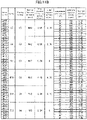
- Figs. 14A and 14B The results of evaluation are shown in Figs. 14A and 14B .
- the samples are arranged in order from the smallest mass per unit area w to the largest, and passed samples that conform both to Reference Standard "a” and Reference Standard “b” and rejected samples for which at least one of these Reference Standard “a” and Reference Standard “b” is not met are shown together.
- Figs. 14A and 14B with respect to respective Reference Standard “a” and Reference Standard “b”, cases for which the corresponding standard is met are shown by “y”, while cases for which the corresponding standard is not met are shown by "n”.
- cases for which both Reference Standard "a” and Reference Standard “b” are met are shown by "YES", while cases for which at least one of Reference Standard "a” or Reference Standard “b” is not met are shown by "NO".
- the mass per unit area w of the passed samples is within the range 0.79 ⁇ w ⁇ 10.07.
- mass production of the flare nuts it is beneficial in terms of production cost to keep the amount of coating material used as small as possible.
- the upper limit value of the mass per unit area w is, for example, less than 9.00 g/m 2 , more preferable for it to be less than 7.50 g/m 2 , and even more preferable for it to be less than 6.00 g/m 2 .
- 0.79 ⁇ w ⁇ 9.00 is preferable, 0.79 ⁇ w ⁇ 7.50 is more preferable, and 0.79 ⁇ w ⁇ 6.00 is even more preferable.
- the mass per unit area w is within any of the ranges described above, the mechanical characteristics required for the flare nut are satisfied. However, it has been found that, if the mass per unit area w is too low, although the mechanical characteristics for the flare nut are satisfied, there is a problem with the corrosion resistance of the flare nut when it is re-used.
- a predetermined number of flare nuts were prepared to perform the fastening test mentioned above upon the flare nuts and test sample groups for which different numbers of trials were performed were created in the following manner.
- the predetermined number of flare nuts having the same dimensions and shapes but with different values of mass per unit area w were prepared, and the fastening test described above was performed upon these flare nuts.
- an unused comparative sample group of flare nuts was prepared having the same dimensions and shapes as the above test sample groups, but different values of mass per unit area w.
- Corrosion testing was performed for each of the test sample groups and the comparison sample group. This testing conformed to the SST (Salt Spray Test) stipulated by JASO 104-86. To summarize the test results, the relationship between corrosion resistance and mass per unit area shown in Fig. 15 was found. The time period (in hours) from the start of the test to the development of white rusting, which indicates the corrosion resistance of the flare nut, is shown along the vertical axis in Fig. 15 . And the mass per unit area w, which is correlated with the thickness of the resin coating layer, is shown along the horizontal axis in Fig. 15 .
- the mass per unit area w is greater than 1.20
- the condition obtained by the fastening tests is 0.79 ⁇ w ⁇ 10.07
- the condition obtained by the corrosion resistance tests is 1.20 ⁇ w. Accordingly, in relation to the mass per unit area w, at least the following Formula (2) is satisfied: 1.20 ⁇ w ⁇ 10.07
- the present invention is not limited to the embodiments described above; it may be implemented in various forms.
- the flare nuts were used upon brake tubes made from metal, but the subject for use of the flare nuts is not limited to being brake tube.
- tubes of various types made from metal, such as vapor tubes or the like may also be employed as subjects.
- Each of the flare nuts 1A, 1B is only an example of a tube fitting that is used for coupling to a metallic tube.
- the present invention can also be applied to flare nuts having shapes different from those shown in the figures, provided that the external thread has an outer diameter of 9.53 through 14.0 mm and the contact portion has an inner diameter of 4.98 through 8.44 mm.
- the coated region R according to the embodiments described above are provided upon the entire surfaces of the flare nut, in other words upon the entire surfaces of the threaded portion, of the head portion, and of the contact portion, and upon the entire inner circumferential surface of the flare nut which a through hole is pierced through.
- the fact that the coated region is provided over these entire surfaces is only an example.
- the coated region may be limited to being provided only upon the surface of the threaded portion and upon the surface of the contact portion.
- the inner circumferential surface of the flare nut which a through hole is pierced through and the surface of the head portion are excluded from the coated region.
- the coated region may not be always set upon the entire surfaces of the threaded portion and the contact portion.
- the coated region might be set only upon portions of the surfaces of the threaded portion and the contact portion.
- the coated region could preferably be set upon an at least 40% portion of the surface of the threaded portion, more preferably could be set upon an at least 60% portion thereof, and even more preferably could be set upon an at least 80% portion thereof.
- the coated region could preferably be set upon an at least 40% portion of the surface of the contact portion, more preferably could be set upon an at least 60% portion thereof, and even more preferably could be set upon an at least 80% portion thereof.
- the surface of the threaded portion is meant the surface of the range over which the screw thread is formed that is actually engaged with the internal screw thread of the mating member, or that is scheduled to be engaged with that internal screw thread.
- the surface of the contact portion is meant the contact surface that is actually in contact with the annular portion, or that is scheduled to be in contact with the annular portion.
- the embodiments described above are only examples in which the resin coating layer 18 is provided upon the surface 17 upon which the zinc based plated layer P1 is provided, and in which the resin coating layer 28 is provided upon the surface 27 upon which the zinc based plated layer P2 is provided.
- the present invention it would also be possible to implement the present invention by employing a metallic substrate upon which no chemical surface processing such as plating or the like has been performed as the surface of a tube fitting, and by providing a resin coating layer upon that surface. Even with this arrangement, the frictional coefficient of the resin coating layer will be smaller than the frictional coefficient of the surface of the metallic substrate.
- a tube equipped with a tube fitting includes: a tube made from metal, the tube being provided with an annular portion upon an end portion thereof, the annular portion projecting in the radially outward direction from the tube, and provided with a bent portion at a position remote from the annular portion; and a tube fitting that is installed upon the external periphery of the tube so as to be prevented from coming off by the annular portion and the bent portion, and that can couple the tube to a mating member by being fastened to the mating member in the state of contacting the annular portion; wherein the tube fitting includes: a threaded portion upon which is formed an external thread that engages with an internal thread provided in the mating member; a contact portion that is provided at the end portion of the tube fitting in the direction of progression of the external thread when the tube fitting is being fastened, and that, when the tube fitting is fastened to the mating member, contacts the annular portion and presses the annular portion against the mating member; and a threaded portion upon which is formed an external thread that engages
- a relation 0.79 ⁇ w ⁇ 10.07 is satisfied with respect to the mass per unit area w, and accordingly, in a case that fastening and release are repeated, it is possible to obtain an initial axial force which keeps a co-rotation torque less than the upper limit value, and moreover it is possible to keep the axial force decrease ratio low.
- a relation 1.20 ⁇ w ⁇ 10.07 may be satisfied with respect to the mass per unit area w.
- this aspect in a case that fastening and release are repeated, it is possible to obtain an initial axial force which keeps a co-rotation torque less than the upper limit value, and moreover it is possible to keep the axial force decrease ratio low; and furthermore it is possible to ensure a corrosion resistance during re-use of the tube fitting that is equivalent to the corrosion resistance upon first use.
- the tube may be a brake tube that is employed as a brake conduit for an automobile, and, when a testing member corresponding to the mating member and a testing tube having the same outer diameter as the tube and having a testing annular portion corresponding to the annular portion may be prepared, and when a fastening test is repeated n times (where 1 ⁇ n ⁇ 6), the fastening test including: fastening operation to fasten the tube fitting to the testing member with a tightening torque in the range of 12.0 to 22.0 Nm, in the state in which the contact portion is contacted against the testing annular portion; and release operation to release the coupling of the testing tube from the testing member by loosening its fastening state after the tightening operation: if the maximum axial force generated in the first performance of the fastening test is termed the initial axial force F 1 (kN) and the maximum axial force generated in the n-th performance of the fastening test is termed the n-th axial force F n (kN), and if
- the relation 0 ⁇ 1.75 is satisfied with respect to the axial force decrease ratio ⁇ , accordingly it is possible to prevent decrease of the axial force during re-use, and it is possible to obtain the desired coupling force during re-use even when frightening is performed with the same tightening torque as that employed upon initial use.
- the relation F 1 ⁇ 14.0 is satisfied with respect to the initial axial force F 1 , accordingly it is possible to guarantee that the upper limit value for the co-rotation torque is not exceeded, and it is possible to prevent induction of loosening of the tube fitting while still avoiding damage to the tube that is employed as a brake conduit.
- a zinc based plated layer may be formed upon the surfaces of the threaded portion and the contact portion, the resin coating layer may be provided over the zinc based plated layer, a zinc-nickel alloy plated layer may be provided as the zinc based plated layer, and the frictional coefficient of the resin coating layer may be smaller than the frictional coefficient of the surfaces formed by the zinc based plated layer. Since, according to this aspect, a zinc-nickel alloy plated layer is provided as the zinc based layer, accordingly enhancement of the corrosion resistance is prominent.
- a tube fitting according to the present invention disclosed is capable of coupling a tube made from metal and provided with an annular portion upon an end portion thereof, to a mating member by being installed upon the external periphery of the tube and by being fastened to the mating member in the state of contacting the annular portion, the annular portion projecting in the radially outward direction from the tube, the tube fitting including: a threaded portion upon which is formed an external thread that engages with an internal thread provided in the mating member; a contact portion that is provided at the end portion of the tube fitting in the direction of progression of the external thread when the tube fitting is being fastened, and that, when the tube fitting is fastened to the mating member, contacts the annular portion to press the annular portion against the mating member; and a resin coating layer provided over a coated region that includes the surfaces of the threaded portion and the contact portion; and wherein: the tube is a brake tube that is employed as a brake conduit for an automobile; a through hole extending in a direction parallel to the direction of
- the relation 0 ⁇ 1.75 is satisfied in relation to the axial force decrease ratio ⁇ , accordingly it is possible to prevent decrease of the axial force during re-use, and it is possible to obtain the desired coupling force during re-use even when fastening is performed with the same tightening torque as that employed upon initial use.
- the relation F 1 ⁇ 14.0 is satisfied in relation to the initial axial force F 1 , accordingly it is possible to guarantee that the upper limit value for the co-rotation torque is not exceeded, and it is possible to prevent induction of loosening of the tube fitting while still avoiding damage to the tube that is employed as a brake conduit.
- the range for the mass per unit area w may be 0.79 ⁇ w ⁇ 10.07. According to this tube fitting, when fastening and release are repeated, it is possible to obtain the initial axial force while keeping the co-rotation torque less than the upper limit value, and moreover it is possible to keep the axial force decrease ratio low.
- a relation 1.20 ⁇ w ⁇ 10.07 may be satisfied with respect to the mass per unit area w.
- this aspect in a case that fastening and release are repeated, it is possible to obtain an initial axial force which keeps a co-rotation torque less than the upper limit value, and moreover it is possible to keep the axial force decrease ratio low; and furthermore it is possible to ensure a corrosion resistance during re-use of the tube fitting that is equivalent to the corrosion resistance upon first use.
- a relation 0.79 ⁇ w ⁇ 9.00, a relation 0.79 ⁇ w ⁇ 7.50, or a relation 0.79 ⁇ w ⁇ 6.00 may be satisfied with respect to the mass per unit area w.
- mass production of flare nuts it is beneficial in terms of production cost that the smaller the upper limit of the mass per unit area w is, the smaller the amount of coating material used becomes.
- An axial force measurement device includes: a frame; a tightening actuation unit that performs tightening operation upon a screw type tube fitting installed upon a tube upon which is formed an annular portion projecting in the radially outward direction from the tube; and a mating member holding unit that holds a testing member into which the tube fitting is screwed and that is coupled to the tube, with the tightening actuation unit and the mating member holding unit being provided to the frame in line along the direction of a reference axis that extends in the direction of the center line of the tube fitting and the tube axis of the tube, wherein the testing member has: a first part through which is pierced a screw hole in which an internal thread that engages with the tube fitting is formed; and a second part having a bottom portion against which the annular portion of the tube is pressed; and the mating member holding unit holds the first part and the second part in a state in which the screw hole of the first part and the
- the axial force of a screw type tube fitting is calculated by dividing the tightening torque by the torque coefficient and the nominal diameter of the screw. Since the torque coefficient is not constant and is set to an appropriate value by experience, the axial force that is calculated is only an approximate value. Due to this, in order to acquire the axial force of the tube fitting accurately, a device that can measure the axial force of the tube fitting directly is required. According to this axial force measurement device, when the tube fitting installed upon the tube is screwed into the member for testing, the tube fitting advances while engaging with the internal thread of the first part, and the annular portion presses against the second part. Due to this, a separating force acts upon the first part and the second part to pull them apart in the direction of the reference axis.
- One of the first part and the second part is held so that it cannot shift in the direction of the reference axis, while movement of the other one of the first part and the second part is restricted in the direction of the reference axis in a state that a load cell is interposed. Due to this, the load in the direction of the reference axis that acts upon that other one of the first part and the second part corresponds to the reaction force of the axial force of the tube fitting. Accordingly, it is possible directly to acquire the axial force of the tube fitting as a measurement value on the basis of the output signal of the load cell, irrespective of any calculation based upon the tightening torque.
- the mating member holding unit may have a first jig (103a) that, along with holding either one of the first part and the second part, is fixed to the frame, and a second jig (103b) of which movement, along with holding the other one of the first part and the second part, is restrained in the direction of the reference axis with the load cell being imposed.
- a further measurement method of axial force is a measurement method of axial force of a tube fitting, where the axial force generated upon a screw type tube fitting is measured, the tube fitting being screwed into a testing member in a state that the tube fitting is installed upon a tube upon which is formed an annular portion projecting radially outward from the tube, the measurement method including: a first step of providing as the testing member, a first part through which is pierced a screw hole in which an internal thread that engages with the tube fitting is formed and a second part having a bottom portion against which the annular portion of the tube is pressed in line along a direction of a reference axis extending in a direction of a tube axis of the tube, so that the screw hole and the bottom portion are in a concentric state; a second step of holding one of the first and second parts provided in line along the direction of the reference axis in a state in which the one of the first and second parts cannot shift in the direction of the reference axis,
Claims (5)
- Rohrverbindung (1A; 1B), die in der Lage ist, ein Rohr (BT), das aus Metall hergestellt ist und mit einem ringförmigen Abschnitt (16; 26) auf einem Endteil davon versehen ist, an ein Gegenstück (MC1; MC2) zu koppeln, indem sie auf einem Außenumfang des Rohrs (BT) montiert wird und indem sie in Berührungszustand mit dem ringförmigen Abschnitt (16; 26) an dem Gegenstück (MC1, MC2) befestigt wird, wobei der ringförmige Abschnitt in eine radiale Richtung nach außen von dem Rohr (BT) vorsteht, wobei die Rohrverbindung (1A; 1B) Folgendes aufweist:einen Gewindeabschnitt (12; 22) auf dem ein Außengewinde (12a; 12a) gebildet ist, das mit einem Innengewinde (12b; 22b), das in dem Gegenstück (MC1; MC2) vorgesehen ist, eingreift;einen Kontaktabschnitt (14; 24), der an dem Endteil der Rohrverbindung in der Verlaufsrichtung des Außengewindes (12a; 22a) vorgesehen ist, wenn die Rohrverbindung befestigt wird, und der, wenn die Rohrverbindung (1A; 1B) an dem Gegenstück (MC1; MC2) befestigt wird, mit dem ringförmigen Abschnitt (16; 26) in Berührung ist, um den ringförmigen Abschnitt (16; 26) gegen das Gegenstück (MC1; MC2) zu drücken; undeine Harzbeschichtungsschicht (18; 28), die über einen beschichteten Bereich (R), der die Oberflächen (17; 27) des Gewindeabschnitts (12; 22) und des Kontaktabschnitts (14; 24) aufweist, vorgesehen ist; undwobei: das Rohr ist ein Bremsrohr, das als eine Bremsleitung für ein Kraftfahrzeug eingesetzt wird;wobei das Rohr ferner ein Durchgangsloch (10; 20), das sich in einer Richtung parallel zu der Verlaufsrichtung erstreckt, aufweist, wobei das Durchgangsloch durch sowohl den Gewindeabschnitt (12; 22) als auch den Kontaktabschnitt (14; 24) durchstoßen wird,wobei das Außengewinde (12a; 22a) einen Außendurchmesser von 9,53 bis 14,0 mm aufweist und der Kontaktabschnitt (14; 24) einen Innendurchmesser von 4,98 bis 8,44 mm aufweist;wobei die Harzbeschichtungsschicht (18; 28) eine Substanz auf Polyethylenbasis, ein Schmiermittel und Feststoffteilchen aufweist; und, wenn die Masse per Einheitsfläche w (g/ m2) als ein Wert, der durch Dividieren der Massendifferenz zwischen einem Zustand mit der Harzbeschichtungsschicht (18; 28) und einem Zustand ohne der Harzbeschichtungsschicht (18; 28) durch eine Oberflächenfläche des beschichteten Bereichs erhalten wird, definiert ist,wobei die Rohrverbindung (1A; 1B) dadurch gekennzeichnet ist, dass,wenn ein Prüfstück (TM), das dem Gegenstück (MC1; MC2) entspricht, und ein Prüfrohr (T), das den gleichen Außendurchmesser wie das Rohr (BT) aufweist und einen ringförmigen Prüfabschnitt (TR) entsprechend dem ringförmigen Abschnitt (16; 26) aufweist, vorbereitet werden, und eine Befestigungsprüfung n-mal (wobei 1<n<6) wiederholt wird, die Befestigungsprüfung Folgendes aufweist: Befestigungsvorgang zum Befestigen der Rohrverbindung (1A; 1B) an dem Prüfstück (TM) mit einem Festziehdrehmoment in dem Bereich von 12,0 bis 2,0 Nm in dem Zustand, in dem der Kontaktabschnitt an dem ringförmigen Abschnitt (TR) anliegt; und Freigabevorgang zum Lösen der Kopplung des Prüfrohrs (T) von dem Prüfstück (TM) durch Lockern eines Befestigungszustands nach dem Befestigungsvorgang,falls die maximale Axialkraft, die bei der ersten Durchführung der Befestigungsprüfung erzeugt wird, als die anfängliche Axialkraft F1 (kN) bestimmt wird, und die maximale Axialkraft, die bei einer n-ten Durchführung der Befestigungsprüfung erzeugt wird, als die n-te Axialkraft FN (kN) bestimmt wird, und falls ein Wert, der durch -(Fn-F1)/(n-1) erhalten wird, als das Axialkraftabnahmeverhältnis a (kN/turn) bestimmt wird, wird der Bereich der Masse per Einheitsfläche w derart bestimmt, dass die Verhältnisse F1<14,0 und 0<α<1,75 erfüllt werden.
- Rohrverbindung nach Anspruch 1, wobei:eine plattierte Schicht (P1, P2) auf Zinkbasis jeweils auf den Oberflächen (17; 27) des Gewindeabschnitts (12; 22) und des Kontaktabschnitts (14; 24) gebildet wird und die Harzbeschichtungsschicht (18; 28) über der plattierten Schicht (P1, P2) auf Zinkbasis vorgesehen ist; undein Reibungskoeffizient der Harzbeschichtungsschicht (18; 28) kleiner als ein Reibungskoeffizient der Oberflächen (17; 27), die durch die plattierte Schicht (P1, P2) auf Zinkbasis gebildet werden, ist.
- Rohrverbindung nach Anspruch 2, wobei eine mit Zink-Nickellegierung plattierte Schicht als die plattierte Schicht (P1, P2) auf Zinkbasis vorgesehen ist.
- Rohrverbindung nach einem der Ansprüche 1 bis 3, wobeidie Harzbeschichtungsschicht (18; 28) durch Haften von Beschichtungsmaterial (C1 bis C4), das die Substanz auf Polyethylenbasis, das Schmiermittel und die Feststoffteilchen aufweist, an den beschichteten Bereich (R) erzeugt wird, undeine Viskosität des Beschichtungsmaterials (C1 bis C4) in einem Bereich von 4,24 bis 5,27 mPa·s bei einer Temperatur von 25°C liegt, gemessen unter Verwendung eines Rotationsviskosimeters, das eine Spindel aufweist und ISO-Norm 2555:1990 erfüllt, wobei eine Drehzahl der Spindel auf 60 U/min eingestellt ist.
- Rohr, das mit einer Rohrverbindung (1A; 1B) nach einem der Ansprüche 1 bis 4 ausgestattet ist, wobeidas Rohr (BT) aus Metall hergestellt ist und mit einem gebogenen Abschnitt (Bp) an einer Stelle entfernt von dem ringförmigen Abschnitt (16; 26) versehen ist, unddie Rohrverbindung (1A; 1B) derart auf einem Außenumfang des Rohrs montiert ist, dass verhindert wird, dass sie sich von dem ringförmigen Abschnitt (16; 26) und dem gebogenen Abschnitt (Bp) löst.
Applications Claiming Priority (2)
| Application Number | Priority Date | Filing Date | Title |
|---|---|---|---|
| JP2019045239A JP6566376B1 (ja) | 2019-02-22 | 2019-02-22 | 管継手及び管継手付きチューブ並びに管継手の製造方法 |
| EP20158202.0A EP3699472B1 (de) | 2019-02-22 | 2020-02-19 | Rohrverbindung, rohr mit einer rohrverbindung und verfahren zur herstellung einer rohrverbindung |
Related Parent Applications (2)
| Application Number | Title | Priority Date | Filing Date |
|---|---|---|---|
| EP20158202.0A Division EP3699472B1 (de) | 2019-02-22 | 2020-02-19 | Rohrverbindung, rohr mit einer rohrverbindung und verfahren zur herstellung einer rohrverbindung |
| EP20158202.0A Division-Into EP3699472B1 (de) | 2019-02-22 | 2020-02-19 | Rohrverbindung, rohr mit einer rohrverbindung und verfahren zur herstellung einer rohrverbindung |
Publications (2)
| Publication Number | Publication Date |
|---|---|
| EP3885622A1 EP3885622A1 (de) | 2021-09-29 |
| EP3885622B1 true EP3885622B1 (de) | 2022-06-29 |
Family
ID=67766603
Family Applications (3)
| Application Number | Title | Priority Date | Filing Date |
|---|---|---|---|
| EP21175341.3A Active EP3892903B1 (de) | 2019-02-22 | 2020-02-19 | Axialkraftmessvorrichtung und messverfahren von axialkraft |
| EP21175368.6A Active EP3885622B1 (de) | 2019-02-22 | 2020-02-19 | Rohranschluss und rohr mit dem rohranschluss |
| EP20158202.0A Active EP3699472B1 (de) | 2019-02-22 | 2020-02-19 | Rohrverbindung, rohr mit einer rohrverbindung und verfahren zur herstellung einer rohrverbindung |
Family Applications Before (1)
| Application Number | Title | Priority Date | Filing Date |
|---|---|---|---|
| EP21175341.3A Active EP3892903B1 (de) | 2019-02-22 | 2020-02-19 | Axialkraftmessvorrichtung und messverfahren von axialkraft |
Family Applications After (1)
| Application Number | Title | Priority Date | Filing Date |
|---|---|---|---|
| EP20158202.0A Active EP3699472B1 (de) | 2019-02-22 | 2020-02-19 | Rohrverbindung, rohr mit einer rohrverbindung und verfahren zur herstellung einer rohrverbindung |
Country Status (4)
| Country | Link |
|---|---|
| US (3) | US11879572B2 (de) |
| EP (3) | EP3892903B1 (de) |
| JP (1) | JP6566376B1 (de) |
| CN (3) | CN111609229B (de) |
Families Citing this family (4)
| Publication number | Priority date | Publication date | Assignee | Title |
|---|---|---|---|---|
| JP7127760B2 (ja) * | 2019-06-20 | 2022-08-30 | 三桜工業株式会社 | 管継手の軸力測定装置及び軸力測定方法 |
| JP2021028535A (ja) | 2019-08-09 | 2021-02-25 | 三桜工業株式会社 | 管継手及び管継手付きチューブ |
| JP2022124434A (ja) * | 2021-02-15 | 2022-08-25 | 三桜工業株式会社 | チューブ曲げ加工システム |
| CN115158269B (zh) * | 2022-07-11 | 2023-07-07 | 东风柳州汽车有限公司 | 一种abs轮速传感器的固定压紧装置 |
Citations (1)
| Publication number | Priority date | Publication date | Assignee | Title |
|---|---|---|---|---|
| DE202017104112U1 (de) * | 2017-07-11 | 2017-07-30 | Ti Automotive (Heidelberg) Gmbh | Schraubelement für den Anschluss von Rohrleitungen und Rohranschlusseinrichtung |
Family Cites Families (47)
| Publication number | Priority date | Publication date | Assignee | Title |
|---|---|---|---|---|
| WO1996010710A1 (fr) * | 1994-10-04 | 1996-04-11 | Nippon Steel Corporation | Union de tuyaux d'acier presentant une resistance elevee au grippage et traitement de surface destine a cet effet |
| JP2000074764A (ja) * | 1998-08-31 | 2000-03-14 | Toshiba Tungaloy Co Ltd | ボルト軸力の測定用ソケット及びトルクレンチ並びにボルト軸力計 |
| US6446510B1 (en) | 2000-07-24 | 2002-09-10 | Kulite Semiconductor Products, Inc. | Force transducer assembly |
| JP3871885B2 (ja) * | 2001-01-09 | 2007-01-24 | 三桜工業株式会社 | 配管用継手 |
| PL203768B1 (pl) * | 2002-05-31 | 2009-11-30 | Sumitomo Metal Ind | Połączenie gwintowe rur stalowych |
| US7025752B2 (en) * | 2002-11-06 | 2006-04-11 | Advanced Cardiovascular Systems, Inc. | Reduced slippage balloon catheter and method of using same |
| JP4646103B2 (ja) * | 2003-06-24 | 2011-03-09 | コニカミノルタエムジー株式会社 | カチオン重合性組成物の保存方法及びそれに用いる保存容器 |
| JP4296418B2 (ja) * | 2004-03-05 | 2009-07-15 | 株式会社阪村機械製作所 | 軸力保障ボルトの検査システム |
| US20050229992A1 (en) * | 2004-04-06 | 2005-10-20 | Mckeen Laurence W | Lined vessels for conveying chemicals |
| JP4599874B2 (ja) * | 2004-04-06 | 2010-12-15 | 住友金属工業株式会社 | 油井管用ねじ継手、及びその製造方法 |
| US7883118B2 (en) * | 2005-03-29 | 2011-02-08 | Sumitomo Metal Industries, Ltd. | Threaded joint for steel pipes |
| CN101341273A (zh) * | 2005-11-01 | 2009-01-07 | 三樱工业株式会社 | 汽车配管用钢管 |
| US7842403B2 (en) * | 2006-02-23 | 2010-11-30 | Atotech Deutschland Gmbh | Antifriction coatings, methods of producing such coatings and articles including such coatings |
| JP5028923B2 (ja) * | 2006-09-14 | 2012-09-19 | 住友金属工業株式会社 | 鋼管用ねじ継手 |
| JP2008078037A (ja) * | 2006-09-22 | 2008-04-03 | Sumitomo Electric Ind Ltd | 電池用電極基板および電池用電極 |
| CN100494758C (zh) * | 2007-03-20 | 2009-06-03 | 应建明 | 一种空间对接机构用保温隔热软罩的制备方法 |
| EP2216576B1 (de) * | 2007-12-04 | 2017-09-20 | Nippon Steel & Sumitomo Metal Corporation | Rohrschraubverbindung |
| CN102066710B (zh) * | 2008-04-16 | 2018-06-22 | 米提亚·维克托·辛德克斯 | 新型往复式机器和其它装置 |
| DE502008001944D1 (de) | 2008-06-17 | 2011-01-13 | Ti Automotive Heidelberg Gmbh | Schraubelement und Rohranschlusseinrichtung für den Anschluss von Rohrleitungen |
| US9109728B2 (en) * | 2008-08-05 | 2015-08-18 | Nippon Pillar Packaging Co., Ltd. | Resinous pipe joint |
| JP2010242195A (ja) * | 2009-04-09 | 2010-10-28 | Kobe Steel Ltd | 異種金属接触腐食に対する防食性に優れた表面処理金属材及びその表面処理金属材を備えた異材接合体 |
| JP5369986B2 (ja) * | 2009-08-07 | 2013-12-18 | 新日鐵住金株式会社 | 塗装金属材とそれを用いてなる筐体 |
| CN101994892A (zh) * | 2009-08-12 | 2011-03-30 | 东丽纤维研究所(中国)有限公司 | 一种金属管道保护补强系统 |
| FR2950667B1 (fr) * | 2009-09-30 | 2011-12-16 | Vallourec Mannesmann Oil & Gas | Composant filete tubulaire resistant au grippage et procede de revetement d'un tel composant |
| KR101156050B1 (ko) * | 2010-01-15 | 2012-07-03 | 한국전력기술 주식회사 | 배관 지지물에 작용하는 하중 측정장치 |
| EP2360405A1 (de) * | 2010-02-19 | 2011-08-24 | TI Automotive (Heidelberg) GmbH | Rohranschlusseinrichtung |
| JP5369050B2 (ja) * | 2010-05-20 | 2013-12-18 | 住友電気工業株式会社 | 高耐食性を有する金属多孔体 |
| CN102278568B (zh) * | 2011-08-19 | 2012-12-19 | 新兴铸管股份有限公司 | 一种具有防水保护层的球墨铸铁管及其生产工艺 |
| AT512806B1 (de) * | 2012-04-23 | 2014-01-15 | Bsw Machinery Handels Gmbh | Gewebe für die Herstellung von Säcken |
| EP2679873B1 (de) * | 2012-06-29 | 2017-05-31 | TI Automotive (Heidelberg) GmbH | Verbindungsaggregat aus einer Kraftfahrzeugrohrleitung und einem Verbindungsfitting |
| DE102012108433C9 (de) * | 2012-09-10 | 2022-11-24 | Cooper-Standard Automotive (Deutschland) Gmbh | Rohrschraube zur Befestigung einer Rohrleitung und ein Verfahren zur Herstellung einer solchen Rohrschraube |
| CN102996975A (zh) * | 2012-12-17 | 2013-03-27 | 济南玫德铸造有限公司 | 带有双重镀层的管件及其制造方法 |
| CN104142203B (zh) * | 2013-07-12 | 2016-06-01 | 河南航天精工制造有限公司 | 高锁螺母松脱力矩测试方法及该测试用卸载轴向力的工装 |
| JP6363084B2 (ja) * | 2013-09-13 | 2018-07-25 | 新日鐵住金ステンレス株式会社 | 廉価で塩害耐食性に優れた自動車用部材の製造方法、自動車用部材、給油管の製造方法および給油管 |
| DE202014102663U1 (de) * | 2014-06-06 | 2014-06-24 | Ti Automotive (Heidelberg) Gmbh | Schraubelement für den Anschluss von Rohrleitungen und Rohranschlusseinrichtung mit diesem Schraubelement |
| US10072778B2 (en) * | 2015-01-08 | 2018-09-11 | Toyota Motor Engineering & Manufacturing North America, Inc. | Tube nut assembly |
| EP3255695A4 (de) * | 2015-02-04 | 2018-10-24 | Toppan Printing Co., Ltd. | Stromspeicherzellenaussengehäusematerial |
| FR3035474B1 (fr) * | 2015-04-23 | 2017-04-28 | Vallourec Oil & Gas France | Element filete tubulaire dote d'un revetement metallique anticorrosion et antigrippage |
| DE102015007867A1 (de) * | 2015-06-10 | 2016-12-15 | ISPT GmbH&Co. KG | Verfahren und Vorrichtung zur Ermittlung charakteristischer Materialkennwerte, insbesondere von Fließkurven von Leichtbauwerkstoffen, insbesondere für das Strangpressen |
| CN105092129B (zh) * | 2015-07-09 | 2018-07-24 | 广东肯富来泵业股份有限公司 | 一种旋转机械的轴向力测试装置及其测试方法 |
| DE102015214193A1 (de) * | 2015-07-27 | 2017-02-02 | Tesa Se | Klebeband für den fliegenden Rollenwechsel |
| EA201890656A1 (ru) * | 2015-09-18 | 2018-11-30 | Ниппон Стил Энд Сумитомо Метал Корпорейшн | Композиция, резьбовое соединение для труб, содержащее покрытие из твердой смазки, сформированное из этой композиции, и способ создания резьбового соединения для труб |
| AR106975A1 (es) * | 2015-12-25 | 2018-03-07 | Nippon Steel & Sumitomo Metal Corp | Conexión roscada para caño o tubo y método para producir la conexión roscada para caño o tubo |
| CN106439260B (zh) * | 2016-12-07 | 2019-04-23 | 大连圣洁热处理科技发展有限公司 | 一种具有复合层结构的球墨铸铁管及其制备方法 |
| KR101737760B1 (ko) * | 2016-12-15 | 2017-05-22 | 김진춘 | 하이브리드 하수관 보강 튜브, 그리고 이의 제조 방법 및 조성물 |
| WO2018216497A1 (ja) * | 2017-05-22 | 2018-11-29 | 新日鐵住金株式会社 | 管用ねじ継手及び管用ねじ継手の製造方法 |
| CN108458825A (zh) * | 2018-02-28 | 2018-08-28 | 易克威系统株式会社 | 螺丝的轴向力和摩擦扭矩测量装置及利用该装置的测量方法 |
-
2019
- 2019-02-22 JP JP2019045239A patent/JP6566376B1/ja active Active
-
2020
- 2020-02-13 CN CN202010090742.3A patent/CN111609229B/zh active Active
- 2020-02-13 CN CN202111062038.8A patent/CN113834594B/zh active Active
- 2020-02-13 CN CN202111061575.0A patent/CN113833916B/zh active Active
- 2020-02-19 US US16/794,969 patent/US11879572B2/en active Active
- 2020-02-19 EP EP21175341.3A patent/EP3892903B1/de active Active
- 2020-02-19 EP EP21175368.6A patent/EP3885622B1/de active Active
- 2020-02-19 EP EP20158202.0A patent/EP3699472B1/de active Active
-
2023
- 2023-11-22 US US18/517,790 patent/US20240084935A1/en active Pending
- 2023-11-22 US US18/517,598 patent/US20240093812A1/en active Pending
Patent Citations (1)
| Publication number | Priority date | Publication date | Assignee | Title |
|---|---|---|---|---|
| DE202017104112U1 (de) * | 2017-07-11 | 2017-07-30 | Ti Automotive (Heidelberg) Gmbh | Schraubelement für den Anschluss von Rohrleitungen und Rohranschlusseinrichtung |
Also Published As
| Publication number | Publication date |
|---|---|
| EP3885622A1 (de) | 2021-09-29 |
| US20200271251A1 (en) | 2020-08-27 |
| CN113833916B (zh) | 2023-02-10 |
| JP6566376B1 (ja) | 2019-08-28 |
| CN113833916A (zh) | 2021-12-24 |
| EP3892903B1 (de) | 2022-06-29 |
| US20240084935A1 (en) | 2024-03-14 |
| CN113834594B (zh) | 2024-03-26 |
| CN111609229B (zh) | 2021-10-15 |
| US11879572B2 (en) | 2024-01-23 |
| EP3699472B1 (de) | 2021-07-21 |
| EP3892903A1 (de) | 2021-10-13 |
| US20240093812A1 (en) | 2024-03-21 |
| JP2020133891A (ja) | 2020-08-31 |
| CN113834594A (zh) | 2021-12-24 |
| CN111609229A (zh) | 2020-09-01 |
| EP3699472A1 (de) | 2020-08-26 |
Similar Documents
| Publication | Publication Date | Title |
|---|---|---|
| EP3885622B1 (de) | Rohranschluss und rohr mit dem rohranschluss | |
| KR101947951B1 (ko) | 관 접속용의 나사 요소와 이 나사 요소를 구비한 관 접속 장치 | |
| TWI423881B (zh) | 抗摩擦塗料、此塗料之製法及包含此塗料之物件 | |
| JP2011137539A (ja) | ブレーキドラムとホイールの取付けツール | |
| US20190277329A1 (en) | Low profile nylon insert lock nut | |
| US8425169B2 (en) | Securing element for screw connections and its use | |
| JP7127760B2 (ja) | 管継手の軸力測定装置及び軸力測定方法 | |
| JP7221486B2 (ja) | 管継手及び管継手付きチューブ | |
| EP4012202A1 (de) | Rohrverbindung und rohr mit einer rohrverbindung | |
| JP2008540961A (ja) | 管連結部の新規な処理方法および設計方法 | |
| JP2020133895A (ja) | 管継手及び管継手付きチューブ並びに管継手の製造方法 | |
| Croccolo et al. | An experimental study on the response of a threadlocker, involving different materials, screw dimensions and thread proportioning | |
| CN208281340U (zh) | 一种连接紧固装置 | |
| CN108019400B (zh) | 一种带有防滑凸起型垫圈与压力传感器的法兰及制造方法 | |
| US11555514B2 (en) | Attachment unit | |
| US20070243044A1 (en) | Wear resistant nut | |
| CN111720405A (zh) | 一种螺栓和自锁螺母组件 | |
| Hoernig et al. | Torque vibrations in automatized screw assembly: Reasons, elimination and virtual testing | |
| JP2018508719A (ja) | 非対称的なコーティングを備える分離可能なねじ式接続部 | |
| CN115885125A (zh) | 用于涂覆螺钉元件的方法、螺钉元件和管道连接装置 | |
| EP4081717A1 (de) | Scharnierhalteranordnung | |
| Westphal | An optimized coating system for fasteners with metric threads | |
| Hua et al. | Degradation of W-DLC Coatings in rolling/sliding applications |
Legal Events
| Date | Code | Title | Description |
|---|---|---|---|
| PUAI | Public reference made under article 153(3) epc to a published international application that has entered the european phase |
Free format text: ORIGINAL CODE: 0009012 |
|
| STAA | Information on the status of an ep patent application or granted ep patent |
Free format text: STATUS: REQUEST FOR EXAMINATION WAS MADE |
|
| 17P | Request for examination filed |
Effective date: 20210608 |
|
| AC | Divisional application: reference to earlier application |
Ref document number: 3699472 Country of ref document: EP Kind code of ref document: P |
|
| AK | Designated contracting states |
Kind code of ref document: A1 Designated state(s): AL AT BE BG CH CY CZ DE DK EE ES FI FR GB GR HR HU IE IS IT LI LT LU LV MC MK MT NL NO PL PT RO RS SE SI SK SM TR |
|
| GRAP | Despatch of communication of intention to grant a patent |
Free format text: ORIGINAL CODE: EPIDOSNIGR1 |
|
| STAA | Information on the status of an ep patent application or granted ep patent |
Free format text: STATUS: GRANT OF PATENT IS INTENDED |
|
| INTG | Intention to grant announced |
Effective date: 20220322 |
|
| GRAS | Grant fee paid |
Free format text: ORIGINAL CODE: EPIDOSNIGR3 |
|
| GRAA | (expected) grant |
Free format text: ORIGINAL CODE: 0009210 |
|
| STAA | Information on the status of an ep patent application or granted ep patent |
Free format text: STATUS: THE PATENT HAS BEEN GRANTED |
|
| AC | Divisional application: reference to earlier application |
Ref document number: 3699472 Country of ref document: EP Kind code of ref document: P |
|
| AK | Designated contracting states |
Kind code of ref document: B1 Designated state(s): AL AT BE BG CH CY CZ DE DK EE ES FI FR GB GR HR HU IE IS IT LI LT LU LV MC MK MT NL NO PL PT RO RS SE SI SK SM TR |
|
| REG | Reference to a national code |
Ref country code: CH Ref legal event code: EP |
|
| REG | Reference to a national code |
Ref country code: DE Ref legal event code: R096 Ref document number: 602020003811 Country of ref document: DE |
|
| REG | Reference to a national code |
Ref country code: AT Ref legal event code: REF Ref document number: 1501557 Country of ref document: AT Kind code of ref document: T Effective date: 20220715 |
|
| REG | Reference to a national code |
Ref country code: IE Ref legal event code: FG4D |
|
| REG | Reference to a national code |
Ref country code: LT Ref legal event code: MG9D |
|
| PG25 | Lapsed in a contracting state [announced via postgrant information from national office to epo] |
Ref country code: SE Free format text: LAPSE BECAUSE OF FAILURE TO SUBMIT A TRANSLATION OF THE DESCRIPTION OR TO PAY THE FEE WITHIN THE PRESCRIBED TIME-LIMIT Effective date: 20220629 Ref country code: NO Free format text: LAPSE BECAUSE OF FAILURE TO SUBMIT A TRANSLATION OF THE DESCRIPTION OR TO PAY THE FEE WITHIN THE PRESCRIBED TIME-LIMIT Effective date: 20220929 Ref country code: LT Free format text: LAPSE BECAUSE OF FAILURE TO SUBMIT A TRANSLATION OF THE DESCRIPTION OR TO PAY THE FEE WITHIN THE PRESCRIBED TIME-LIMIT Effective date: 20220629 Ref country code: HR Free format text: LAPSE BECAUSE OF FAILURE TO SUBMIT A TRANSLATION OF THE DESCRIPTION OR TO PAY THE FEE WITHIN THE PRESCRIBED TIME-LIMIT Effective date: 20220629 Ref country code: GR Free format text: LAPSE BECAUSE OF FAILURE TO SUBMIT A TRANSLATION OF THE DESCRIPTION OR TO PAY THE FEE WITHIN THE PRESCRIBED TIME-LIMIT Effective date: 20220930 Ref country code: FI Free format text: LAPSE BECAUSE OF FAILURE TO SUBMIT A TRANSLATION OF THE DESCRIPTION OR TO PAY THE FEE WITHIN THE PRESCRIBED TIME-LIMIT Effective date: 20220629 Ref country code: BG Free format text: LAPSE BECAUSE OF FAILURE TO SUBMIT A TRANSLATION OF THE DESCRIPTION OR TO PAY THE FEE WITHIN THE PRESCRIBED TIME-LIMIT Effective date: 20220929 |
|
| REG | Reference to a national code |
Ref country code: NL Ref legal event code: MP Effective date: 20220629 |
|
| REG | Reference to a national code |
Ref country code: AT Ref legal event code: MK05 Ref document number: 1501557 Country of ref document: AT Kind code of ref document: T Effective date: 20220629 |
|
| PG25 | Lapsed in a contracting state [announced via postgrant information from national office to epo] |
Ref country code: RS Free format text: LAPSE BECAUSE OF FAILURE TO SUBMIT A TRANSLATION OF THE DESCRIPTION OR TO PAY THE FEE WITHIN THE PRESCRIBED TIME-LIMIT Effective date: 20220629 Ref country code: LV Free format text: LAPSE BECAUSE OF FAILURE TO SUBMIT A TRANSLATION OF THE DESCRIPTION OR TO PAY THE FEE WITHIN THE PRESCRIBED TIME-LIMIT Effective date: 20220629 |
|
| PG25 | Lapsed in a contracting state [announced via postgrant information from national office to epo] |
Ref country code: NL Free format text: LAPSE BECAUSE OF FAILURE TO SUBMIT A TRANSLATION OF THE DESCRIPTION OR TO PAY THE FEE WITHIN THE PRESCRIBED TIME-LIMIT Effective date: 20220629 |
|
| PG25 | Lapsed in a contracting state [announced via postgrant information from national office to epo] |
Ref country code: SM Free format text: LAPSE BECAUSE OF FAILURE TO SUBMIT A TRANSLATION OF THE DESCRIPTION OR TO PAY THE FEE WITHIN THE PRESCRIBED TIME-LIMIT Effective date: 20220629 Ref country code: SK Free format text: LAPSE BECAUSE OF FAILURE TO SUBMIT A TRANSLATION OF THE DESCRIPTION OR TO PAY THE FEE WITHIN THE PRESCRIBED TIME-LIMIT Effective date: 20220629 Ref country code: RO Free format text: LAPSE BECAUSE OF FAILURE TO SUBMIT A TRANSLATION OF THE DESCRIPTION OR TO PAY THE FEE WITHIN THE PRESCRIBED TIME-LIMIT Effective date: 20220629 Ref country code: PT Free format text: LAPSE BECAUSE OF FAILURE TO SUBMIT A TRANSLATION OF THE DESCRIPTION OR TO PAY THE FEE WITHIN THE PRESCRIBED TIME-LIMIT Effective date: 20221031 Ref country code: ES Free format text: LAPSE BECAUSE OF FAILURE TO SUBMIT A TRANSLATION OF THE DESCRIPTION OR TO PAY THE FEE WITHIN THE PRESCRIBED TIME-LIMIT Effective date: 20220629 Ref country code: EE Free format text: LAPSE BECAUSE OF FAILURE TO SUBMIT A TRANSLATION OF THE DESCRIPTION OR TO PAY THE FEE WITHIN THE PRESCRIBED TIME-LIMIT Effective date: 20220629 Ref country code: AT Free format text: LAPSE BECAUSE OF FAILURE TO SUBMIT A TRANSLATION OF THE DESCRIPTION OR TO PAY THE FEE WITHIN THE PRESCRIBED TIME-LIMIT Effective date: 20220629 |
|
| PG25 | Lapsed in a contracting state [announced via postgrant information from national office to epo] |
Ref country code: PL Free format text: LAPSE BECAUSE OF FAILURE TO SUBMIT A TRANSLATION OF THE DESCRIPTION OR TO PAY THE FEE WITHIN THE PRESCRIBED TIME-LIMIT Effective date: 20220629 Ref country code: IS Free format text: LAPSE BECAUSE OF FAILURE TO SUBMIT A TRANSLATION OF THE DESCRIPTION OR TO PAY THE FEE WITHIN THE PRESCRIBED TIME-LIMIT Effective date: 20221029 |
|
| REG | Reference to a national code |
Ref country code: DE Ref legal event code: R097 Ref document number: 602020003811 Country of ref document: DE |
|
| PG25 | Lapsed in a contracting state [announced via postgrant information from national office to epo] |
Ref country code: AL Free format text: LAPSE BECAUSE OF FAILURE TO SUBMIT A TRANSLATION OF THE DESCRIPTION OR TO PAY THE FEE WITHIN THE PRESCRIBED TIME-LIMIT Effective date: 20220629 |
|
| PG25 | Lapsed in a contracting state [announced via postgrant information from national office to epo] |
Ref country code: DK Free format text: LAPSE BECAUSE OF FAILURE TO SUBMIT A TRANSLATION OF THE DESCRIPTION OR TO PAY THE FEE WITHIN THE PRESCRIBED TIME-LIMIT Effective date: 20220629 Ref country code: CZ Free format text: LAPSE BECAUSE OF FAILURE TO SUBMIT A TRANSLATION OF THE DESCRIPTION OR TO PAY THE FEE WITHIN THE PRESCRIBED TIME-LIMIT Effective date: 20220629 |
|
| PGFP | Annual fee paid to national office [announced via postgrant information from national office to epo] |
Ref country code: FR Payment date: 20230208 Year of fee payment: 4 |
|
| PLBE | No opposition filed within time limit |
Free format text: ORIGINAL CODE: 0009261 |
|
| STAA | Information on the status of an ep patent application or granted ep patent |
Free format text: STATUS: NO OPPOSITION FILED WITHIN TIME LIMIT |
|
| PGFP | Annual fee paid to national office [announced via postgrant information from national office to epo] |
Ref country code: DE Payment date: 20230228 Year of fee payment: 4 |
|
| 26N | No opposition filed |
Effective date: 20230330 |
|
| PG25 | Lapsed in a contracting state [announced via postgrant information from national office to epo] |
Ref country code: SI Free format text: LAPSE BECAUSE OF FAILURE TO SUBMIT A TRANSLATION OF THE DESCRIPTION OR TO PAY THE FEE WITHIN THE PRESCRIBED TIME-LIMIT Effective date: 20220629 |
|
| PG25 | Lapsed in a contracting state [announced via postgrant information from national office to epo] |
Ref country code: MC Free format text: LAPSE BECAUSE OF FAILURE TO SUBMIT A TRANSLATION OF THE DESCRIPTION OR TO PAY THE FEE WITHIN THE PRESCRIBED TIME-LIMIT Effective date: 20220629 |
|
| REG | Reference to a national code |
Ref country code: CH Ref legal event code: PL |
|
| REG | Reference to a national code |
Ref country code: BE Ref legal event code: MM Effective date: 20230228 |
|
| PG25 | Lapsed in a contracting state [announced via postgrant information from national office to epo] |
Ref country code: LU Free format text: LAPSE BECAUSE OF NON-PAYMENT OF DUE FEES Effective date: 20230219 Ref country code: LI Free format text: LAPSE BECAUSE OF NON-PAYMENT OF DUE FEES Effective date: 20230228 Ref country code: CH Free format text: LAPSE BECAUSE OF NON-PAYMENT OF DUE FEES Effective date: 20230228 |
|
| REG | Reference to a national code |
Ref country code: IE Ref legal event code: MM4A |
|
| PG25 | Lapsed in a contracting state [announced via postgrant information from national office to epo] |
Ref country code: IT Free format text: LAPSE BECAUSE OF FAILURE TO SUBMIT A TRANSLATION OF THE DESCRIPTION OR TO PAY THE FEE WITHIN THE PRESCRIBED TIME-LIMIT Effective date: 20220629 Ref country code: IE Free format text: LAPSE BECAUSE OF NON-PAYMENT OF DUE FEES Effective date: 20230219 |
|
| PG25 | Lapsed in a contracting state [announced via postgrant information from national office to epo] |
Ref country code: BE Free format text: LAPSE BECAUSE OF NON-PAYMENT OF DUE FEES Effective date: 20230228 |