EP3885588A1 - Isolierhülse - Google Patents
Isolierhülse Download PDFInfo
- Publication number
- EP3885588A1 EP3885588A1 EP21159814.9A EP21159814A EP3885588A1 EP 3885588 A1 EP3885588 A1 EP 3885588A1 EP 21159814 A EP21159814 A EP 21159814A EP 3885588 A1 EP3885588 A1 EP 3885588A1
- Authority
- EP
- European Patent Office
- Prior art keywords
- sleeve
- tabs
- insulating sleeve
- tab
- insulating
- Prior art date
- Legal status (The legal status is an assumption and is not a legal conclusion. Google has not performed a legal analysis and makes no representation as to the accuracy of the status listed.)
- Granted
Links
Images


Classifications
-
- F—MECHANICAL ENGINEERING; LIGHTING; HEATING; WEAPONS; BLASTING
- F16—ENGINEERING ELEMENTS AND UNITS; GENERAL MEASURES FOR PRODUCING AND MAINTAINING EFFECTIVE FUNCTIONING OF MACHINES OR INSTALLATIONS; THERMAL INSULATION IN GENERAL
- F16B—DEVICES FOR FASTENING OR SECURING CONSTRUCTIONAL ELEMENTS OR MACHINE PARTS TOGETHER, e.g. NAILS, BOLTS, CIRCLIPS, CLAMPS, CLIPS OR WEDGES; JOINTS OR JOINTING
- F16B19/00—Bolts without screw-thread; Pins, including deformable elements; Rivets
- F16B19/02—Bolts or sleeves for positioning of machine parts, e.g. notched taper pins, fitting pins, sleeves, eccentric positioning rings
-
- F—MECHANICAL ENGINEERING; LIGHTING; HEATING; WEAPONS; BLASTING
- F16—ENGINEERING ELEMENTS AND UNITS; GENERAL MEASURES FOR PRODUCING AND MAINTAINING EFFECTIVE FUNCTIONING OF MACHINES OR INSTALLATIONS; THERMAL INSULATION IN GENERAL
- F16B—DEVICES FOR FASTENING OR SECURING CONSTRUCTIONAL ELEMENTS OR MACHINE PARTS TOGETHER, e.g. NAILS, BOLTS, CIRCLIPS, CLAMPS, CLIPS OR WEDGES; JOINTS OR JOINTING
- F16B5/00—Joining sheets or plates, e.g. panels, to one another or to strips or bars parallel to them
- F16B5/02—Joining sheets or plates, e.g. panels, to one another or to strips or bars parallel to them by means of fastening members using screw-thread
- F16B5/0258—Joining sheets or plates, e.g. panels, to one another or to strips or bars parallel to them by means of fastening members using screw-thread using resiliently deformable sleeves, grommets or inserts
-
- H—ELECTRICITY
- H01—ELECTRIC ELEMENTS
- H01B—CABLES; CONDUCTORS; INSULATORS; SELECTION OF MATERIALS FOR THEIR CONDUCTIVE, INSULATING OR DIELECTRIC PROPERTIES
- H01B17/00—Insulators or insulating bodies characterised by their form
- H01B17/56—Insulating bodies
-
- H—ELECTRICITY
- H02—GENERATION; CONVERSION OR DISTRIBUTION OF ELECTRIC POWER
- H02G—INSTALLATION OF ELECTRIC CABLES OR LINES, OR OF COMBINED OPTICAL AND ELECTRIC CABLES OR LINES
- H02G3/00—Installations of electric cables or lines or protective tubing therefor in or on buildings, equivalent structures or vehicles
- H02G3/22—Installations of cables or lines through walls, floors or ceilings, e.g. into buildings
Definitions
- the invention relates to an insulating sleeve with the features of the preamble of claim 1 and a fastening arrangement with such an insulating sleeve.
- the insulating sleeve according to the invention is specifically intended for an electrically insulated fastening of a holder of an overhead line of an electric railway or tram in tunnels.
- Overhead lines are fastened with rod-shaped or ladder-like or grid-like supports, which in turn are fastened to holding plates.
- the retaining plates are fastened in the tunnel with typically three or four rod-shaped anchors which are anchored in a tunnel ceiling or a tunnel wall.
- the retaining plates have through holes through which the anchors penetrate.
- An insulating sleeve according to the invention is arranged on each of the anchors and in the through holes and electrically isolates the anchors and the holding plate from one another.
- the insulating sleeve according to the invention is not a high-voltage insulator, but the carrier is electrically isolated from the overhead line and / or from the retaining plate with a high-voltage insulator.
- the insulating sleeve according to the invention is intended to prevent leakage currents between the holding plate and the armature.
- the insulating sleeve according to the invention is not limited to the aforementioned purpose.
- the insulating sleeve can be used in systems with highly sensitive electrical components. With such sensitive components, it is important that leakage currents are almost completely avoided, for which the insulating sleeve according to the invention is suitable.
- the insulating sleeve according to the invention enables an efficient, electrically insulated arrangement of an attachment part having a through hole on a rod-shaped armature which extends through the through hole.
- An anchor can be, for example, a composite or expansion anchor for anchoring in concrete or a screw that is screwed into an anchor base or braced by means of a nut.
- the patent discloses a simple insulating sleeve GB 178 849 .
- This insulating sleeve consists of two nested, that is to say telescopic, tubular sleeves made of an electrically insulating material, the axial length of which can be adjusted by axially displacing the two sleeves.
- the object of the invention is to propose an insulating sleeve for electrically insulated fastening of an attachment part having a through hole on a rod-shaped armature that extends through the through hole.
- the insulating sleeve according to the invention has two sleeve parts which can be telescoped into one another.
- Telescopic means that the sleeve parts can be displaced relative to one another, so that a length of the insulating sleeve changes.
- the "length" of the insulating sleeve is the dimension in which the sleeve extends in the direction in which an anchor passes through the insulating sleeve after assembly. Telescoping is therefore carried out in the longitudinal direction, that is, in the direction. in which the insulating sleeve extends along a longitudinal axis.
- Each sleeve part has a pipe section and at least one tab.
- the pipe sections of the sleeve parts are closed in the circumferential direction about the longitudinal axis.
- the tabs of the sleeve parts protrude from the respective tube section of the sleeve part, in particular in or against the longitudinal axis.
- the tab of one sleeve part slides on or in the pipe section of the other sleeve part.
- the tabs abut one another in the circumferential direction of the two sleeve parts or engage between one another, so that they form a full-area jacket surface that is closed in the circumferential direction.
- the closed outer surface ensures efficient electrical insulation between attachment and armature and no or only very low leakage currents can flow between attachment and armature.
- the two sleeve parts of the insulating sleeve according to the invention can be inserted from opposite sides into a through hole of an attachment, the two sleeve parts also being plugged together at the same time to form the insulating sleeve. Because the sleeve parts can be telescoped, a length of the insulating sleeve can be adapted to a thickness of the attachment part. Since the tabs slide over or in the pipe section of the other tab when telescoping, the outer surface of the insulating sleeve according to the invention remains closed when telescoping.
- the attachment can be placed on a rod-shaped anchor that is already fastened in the anchor base, so that the anchor reaches through the insulating sleeve in the through hole.
- the anchor can be pushed through the insulating sleeve for anchoring in an anchor base.
- the insulating sleeve electrically isolates the attachment from the armature. It forms an electrically insulating sheath of the armature, which is closed in the circumferential direction and in the axial direction, in the through hole of the attachment, whereby leakage currents are prevented or at least greatly reduced.
- the insulating sleeve forms a fastening arrangement according to the invention.
- the two sleeve parts are preferably non-rotatably relative to one another, “non-rotatably” here means that the two sleeve parts cannot be rotated relative to one another about the longitudinal axis.
- the torsional strength is due to the fact that the tabs of the sleeve parts bear against one another in the circumferential direction of the two sleeve parts.
- a preferred embodiment of the invention provides a radial flange on one and preferably on both sleeve parts.
- the radial flange electrically isolates the attachment from, for example, a nut screwed onto the rod-shaped armature.
- the radial flange (s) can serve as stop elements, whereby maximum telescoping capability is limited to the thickness of the attachment.
- the insulating sleeves can be telescoped into one another to such an extent that the respective radial flange comes into contact with the attachment.
- one embodiment of the invention provides a holder on an outside of the sleeve part with which the washer is coaxial with the pipe section can be attached to the sleeve part.
- the holder is preferably a snap device into which the washer can be snapped.
- “Outside” refers to a state of the two sleeve parts of the insulating sleeve assembled in the intended manner.
- the outside of the sleeve part is on the outside when the two sleeve parts are put together as intended.
- the washer and / or the sleeve part or the insulating sleeve can also consist of materials other than metal or plastic.
- One or both sleeve parts of the insulating sleeve can have a holder for a concentric arrangement of a washer.
- the bracket simplifies assembly. If the attachment is attached to the anchor base by means of the anchor and the insulating sleeve according to the invention, the washer will hold by itself and the bracket is no longer required.
- the radial flange of one sleeve part has an opening for each tab of the other sleeve part, through which the at least one tab of the other sleeve part can pass.
- the two sleeve parts can not only be pushed together until the tab (s) of one sleeve part abut the radial flange of the other sleeve part, but the two sleeve parts can be pushed together further, with the tab (s) of one sleeve part passing through the opening (s) in the radial flange of the step through the other part of the sleeve.
- the openings increase a telescopic length or the displacement path of the two sleeve parts against each other.
- the openings can have the shape of a cross section of the respectively assigned tab. Larger openings are also possible.
- the two sleeve parts are identical, so that they can be plugged together in mirror image. This eliminates the need to manufacture different sleeve parts and there is no need to choose different sleeve parts for plugging together. In addition, both sleeve parts can be produced with the same injection molding tool.
- the sleeve parts can each have a tab that extends, for example, 180 ° in the circumferential direction, or the sleeve parts each have several tabs, which preferably extend less far in the circumferential direction according to their number.
- the tabs of one sleeve part are axially symmetrical to the free spaces between the tabs of the other sleeve part, so that the tabs of one sleeve part engage in the free spaces between the tabs of the other sleeve part and the tabs of the two sleeve parts that engage between each other together one in the circumferential direction form closed, tubular insulation.
- the number of tabs is thus equal to the number of free spaces.
- the tabs in this embodiment of the invention are axially symmetrical to the free spaces, and if there is an even number of tabs and free spaces between the tabs per sleeve part, the tabs in this embodiment of the invention are axially symmetrical to one another.
- a preferred embodiment of the invention provides that the sleeve parts have several tabs which are arranged evenly distributed over a circumference and which extend in the circumferential direction to the same extent as their distances from one another in the circumferential direction or as the width of their free spaces between the tabs.
- This embodiment of the invention enables identical sleeve parts that can be plugged together in such a way that the tabs of one sleeve part engage in the free spaces formed by the spaces between the tabs of the other sleeve part and the tabs bridge the spaces between the tabs of the other sleeve part without a gap, so that a tubular insulation that is closed in the circumferential direction is formed.
- the tabs of the two sleeve parts are preferably concentric with one another and with the pipe sections and the pipe sections are coaxial with one another.
- the at least one tab is also preferably in the shape of a cylinder shell and the pipe section is cylindrical, although other round and / or angular shapes are possible.
- the at least one tab is arranged without a gap inside or outside on a circumference of the pipe section.
- one embodiment of the invention provides a snap device which releasably holds the two sleeve parts against one another in fixed sliding positions against displacement.
- the snap device can, for example, have a rack-like profile running in a longitudinal direction on the inside or outside of at least one tab of a sleeve part, which engages in a complementary profile, also running in the longitudinal direction, on the outside or inside of the pipe section of the other sleeve part.
- the profiles can be disengaged by an axial force and the two sleeve parts can be moved against each other until they snap into each other again.
- FIGS 1a and 1b show a sleeve part 1 of an insulating sleeve 2 according to the invention.
- the sleeve part 1 consists of plastic or another electrically insulating material.
- Two preferably identical sleeve parts 1 are plugged together to form the insulating sleeve 2, as is the case Figure 1c shows.
- the sleeve part 1 has a radial flange 3 in the form of a perforated disk, from which a pipe section 4 protrudes.
- the sleeve part 1 On an outer circumference of the pipe section 4, the sleeve part 1 has a tab 5 which extends approximately twice as far away from the radial flange 3 as the pipe section 4.
- the radial flange 3, the pipe section 4 and the tab 5 are concentric and integral with one another to each other.
- the pipe section 4 is cylindrical and the bracket 5 is cylindrical, an inner diameter of the pipe section 4 is the same size as a diameter of a central hole of the radial flange 3, and an inner diameter of the bracket 5 is as large as an outer diameter of the pipe section 4, with an inner circumference of the Tab 5 is located on an outer circumference of the pipe section 4 without a gap.
- the described shapes and arrangements of the radial flange 3, the pipe section 4 and the tab 5 apply to the illustrated and described exemplary embodiment and also to the two further exemplary embodiments of the invention, but are not mandatory for the invention. Other shapes and arrangements of the radial flange 3, the pipe section 4 and the tab 5 are possible.
- a multi-piece design of the sleeve part 1 is also possible.
- the tab 5 extends over 180 ° in the circumferential direction, so it has the shape of a semi-cylindrical shell.
- the radial flange 3 has an opening 6 which coaxially encloses the pipe section 4 in a circumferential section which the tab 5 leaves free.
- the opening 6 is so large and so arranged that the tab 5 of another, identical sleeve part 1 can pass through.
- the opening 6 has the shape of a cross section of the tab 5, that is, in the exemplary embodiment, the opening 6 is a semicircular arc-shaped slot which has the same diameter as the tab 5, which is as wide as the tab 5 and which is extends over the circumferential section which the tab 5 leaves free.
- two identical sleeve parts 1 are inserted from opposite sides into a through hole 7 of an attachment part 8, whereby the two sleeve parts 1 also become the insulating sleeve 2 according to the invention are plugged together.
- the tab 5 of one sleeve part 1 slides on the outer circumference of the pipe section 4 of the other sleeve part 1, whereby the two sleeve parts 1 are axially displaceable in the longitudinal direction, which can also be referred to as "telescopic".
- the two semi-cylindrical shell-shaped tabs 5 complement one another to form a tubular sleeve closed in the circumferential direction, that is to say they have a full-surface lateral surface. Together with the pipe sections 4, the tabs 5 form a continuous tubular sleeve, even in the axial direction, without interruption between the radial flanges 5 of the two sleeve parts 1.
- the two sleeve parts 1 can be pushed together until their pipe sections 4 butt against each other.
- the tabs 5 can pass through the openings 6 in the radial flanges 3, so that the tabs 5 do not restrict the two sleeve parts 1 from being pushed together.
- the two sleeve parts 1 are pushed together so far that their radial flanges 3 rest on both sides of the attachment 8, whereby an axial length of the insulating sleeve 2 is adapted to a thickness of the attachment 8.
- the attachment 8 With its through hole 7, in which the insulating sleeve 2 is located, is placed in the longitudinal direction on a rod-shaped armature 9 which extends through the through hole 7 in the longitudinal direction.
- the attachment 8 is fixed on the anchor 9 with nuts 10, which are or will be screwed onto the armature 9 on both sides of the attachment 8. Washers 11 can be arranged between the nuts 10 and the radial flanges 3 of the insulating sleeve 2.
- the insulating sleeve 2 electrically isolates the attachment 8 both in the through hole 7 and in the edge areas of surfaces of the attachment 8 surrounding the through hole 7 from the armature 9 which extends through the through hole 7.
- the tabs 5 which engage between each other and the pipe sections 4 of the two sleeve parts 1 form a tubular, electrical insulation that is closed in the circumferential direction and in the axial direction between the armature 9 and the attachment 8 and the radial flanges 3 form insulating washers on the surfaces of the attachment 8.
- the attachment 8 is a holding plate to which a holding arm (not shown) or the like for fastening an overhead line of an electric road or railroad can be fastened.
- the anchor 9 is a rod-shaped anchor which is anchored in an anchor base 12, for example in a tunnel wall or tunnel ceiling of a tunnel.
- the holding plate forming the attachment 8 has three or four through holes 7, into each of which an insulating sleeve 2 is inserted and to which it is fastened with an anchor as anchor 9.
- the insulating sleeve 2 is not a high-voltage insulator, but rather insulates the attachment 8 electrically against leakage currents from the armature 9.
- the holding arm, not shown, for fastening the overhead line has a high-voltage insulator.
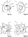
- each sleeve part 1 shows Figures 2a to 2d a radial flange 3 in the form of a perforated disk, a pipe section 4 projecting concentrically therefrom, and tabs 5 likewise arranged concentrically on an outer circumference of the pipe section 4.
- each sleeve part 1 shows Figures 2a to 2d two instead of one tab 5.
- the tabs 5 are arranged evenly distributed over a circumference and the distances between the tabs 5 in the circumferential direction are as large as the tabs 5 extend in the circumferential direction. That is, the two tabs 5 of each sleeve part 1 from Figures 2a to 2d are quarter-cylinder shell-shaped and extend over 90 ° in the circumferential direction, so that there is a distance of 90 ° in the circumferential direction between the tabs 5 of a sleeve part 1.
- the tabs 5 of another, identical sleeve part 1 engage when the two sleeve parts 1 are plugged together to form the insulating sleeve 2 according to the invention.
- the two sleeve parts 1 plugged together to form the insulating sleeve 2 show the Figures 2c and 2b .
- the lugs 5 of a sleeve part 1 can also be designed as axially symmetrical to the lugs 5 of another sleeve part 1 if the sleeve parts 1 have an even number of lugs 5, and as axially symmetrical to the free spaces between the lugs 5 of the other sleeve part 1 if the sleeve parts 1 have an odd number of tabs 5, can be considered.
- the radial flange 3 of a sleeve part 1 has an opening 6 for each of the two tabs 5 of the other sleeve part 1, which is in Figures 2a to 2d extends over a quarter circle.
- the insulating sleeve 2 or its sleeve parts 1 are made of Figures 2a to 2d consistent with that out Figures 1a to 1c trained and functions in the same way.
- the sleeve parts 1 While in Figures 1a to 1c holding the two sleeve parts 1 together in a clamping manner, the sleeve parts 1 show Figures 2a to 2d a snap device 13 to hold them against unintentional displacement against each other.
- the snap device 13 has a first rack-like profile 14 on the inside of an inner circumference of the tabs 5, which extends axially parallel and which interacts with a second rack-like profile 15 on the outer circumference of the pipe section 4 of the other sleeve part 1.
- the rack-like profiles 14, 15 interlock and hold the two sleeve parts 1 against one another against displacement.
- the two rack-like profiles 14, 15 disengage so that the sleeve parts 1 can be axially displaced relative to one another.
- the rack-like profiles 14, 15, which form the snap device 13, snap into one another again.
- the two sleeve parts 1 of the insulating sleeve 2 consist of Figures 2a to 2d in addition to the snap device 13, also hold them together in a clamping manner to prevent unintentional displacement.
- the sleeve part 1 has three cylindrical shell-shaped tabs 5 which each extend over 60 ° in the circumferential direction and between which there are free spaces of also 60 ° in the circumferential direction.
- the openings 6 in the radial flange 3 are circular arc-shaped slots which extend over the free space between the tabs 5, that is also over 60 ° in the circumferential direction.
- Embodiments of the insulating sleeve 2 according to the invention with sleeve parts 1 which have four or more tabs 5 are possible (not shown).
- FIG. 1 shows that in Figures 4a, b
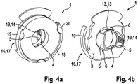
- the sleeve part 1 shown additionally has a snap device 16 as a holder 17 for a washer 18. Otherwise the sleeve parts are in Figures 2a, b and 4a, b identical.
- the snap device 16 or bracket 17 holds the washer 18 on an outside of the radial flange 3 concentric to the pipe section 4. The outside is facing away from the pipe section 4 and the tabs 5 and is located on mutually opposite outer sides or end faces of the insulating sleeve 2, if two sleeve parts 1 like provided to the insulating sleeve 2 are assembled.
- the snap device 16 forming the holder 17 for the washer 18 has, in the exemplary embodiment, two circular arc-shaped, radially resilient spring arms 19 on a circumference of the radial flange 3, which the washer 18, when it is snapped into place between the spring arms 19, over a circumference of more than 180 ° encompass.
- the spring arms 19 or the snap device 16 or holder 17 - in the exemplary embodiment three - have radially inwardly projecting retaining tabs 20, which the washer 18 on a radial flange 3 facing away Reach over the side and thereby hold it on the radial flange 3.
- the sleeve part 1 is made of Figures 2a, b does not have - the sleeve parts 1 from Figures 2a, b and Figures 4a, b identical, so to explain the Figures 4a, b in addition to the explanations of Figures 2a , b or the other figures can be referred to.
Landscapes
- Engineering & Computer Science (AREA)
- General Engineering & Computer Science (AREA)
- Mechanical Engineering (AREA)
- Insulating Bodies (AREA)
Abstract
Description
- Die Erfindung betrifft eine Isolierhülse mit den Merkmalen des Oberbegriffs des Anspruchs 1 und eine Befestigungsanordnung mit einer solchen Isolierhülse.
- Die erfindungsgemäße Isolierhülse ist speziell für eine elektrisch isolierte Befestigung einer Halterung einer Oberleitung einer elektrischen Eisen- oder Straßenbahn in Tunneln vorgesehen. Oberleitungen werden mit stangenförmigen oder leiter- oder gitterartigen Trägern befestigt, die ihrerseits an Halteplatten befestigt werden. Die Halteplatten werden mit typischerweise drei oder vier stangenförmigen Ankern, die in einer Tunneldecke oder einer Tunnelwand verankert sind, im Tunnel befestigt. Dazu weisen die Halteplatten Durchgangslöcher auf, die von den Ankern durchgriffen werden. Auf den Ankern und in den Durchgangslöchern wird jeweils eine erfindungsgemäße Isolierhülse angeordnet, die die Anker und die Halteplatte elektrisch voneinander isoliert. Die erfindungsgemäße Isolierhülse ist kein Hochspannungsisolator, sondern es wird der Träger mit einem Hochspannungsisolator elektrisch von der Oberleitung und/oder von der Halteplatte isoliert. Die erfindungsgemäße Isolierhülse soll Kriechströme zwischen der Halteplatte und dem Anker verhindern. Die erfindungsgemäße Isolierhülse ist nicht auf den zuvor genannten Einsatzzweck beschränkt. Insbesondere ist ein Einsatz der Isolierhülse in Systemen mit hoch sensiblen elektrischen Bauteilen möglich. Bei derart sensiblen Bauteilen ist es wichtig, dass Kriechströme nahezu gänzlich vermieden werden, wozu die erfindungsgemäße Isolierhülse geeignet ist.
- Allgemein ermöglicht die erfindungsgemäße Isolierhülse eine effiziente elektrisch isolierte Anordnung eines ein Durchgangsloch aufweisenden Anbauteils auf einem stangenförmigen Anker, der das Durchgangsloch durchgreift. Ein Anker kann beispielsweise eine Verbund- oder Spreizanker zu Verankerung in Beton oder eine Schraube sein, die in einen Ankergrund eingeschraubt oder mittels eine Mutter verspannt wird.
- Eine einfache Isolierhülse offenbart das Patent
GB 178 849 - Aufgabe der Erfindung ist, eine Isolierhülse zu einer elektrisch isolierten Befestigung eines ein Durchgangsloch aufweisenden Anbauteils auf einem stangenförmigen, das Durchgangsloch durchgreifenden Anker vorzuschlagen.
- Diese Aufgabe wird erfindungsgemäß durch die Merkmale des Anspruchs 1 gelöst. Die erfindungsgemäße Isolierhülse weist zwei ineinander teleskopierbare Hülsenteile auf. "Teleskopierbar" bedeutet, dass die Hülsenteile gegeneinander verschiebbar sind, so dass sich eine Länge der Isolierhülse ändert. Die "Länge" der Isolierhülse ist die Abmessung, in der sich die Hülse in der Richtung erstreckt, in die nach der Montage ein Anker die Isolierhülse durchgreift. Das Teleskopieren erfolgt somit in Längsrichtung, also in der Richtung. in der sich die Isolierhülse entlang einer Längsachse erstreckt. Jedes Hülsenteil weist einen Rohrabschnitt und mindestens eine Lasche auf. Insbesondere sind die Rohrabschnitte der Hülsenteile in Umfangsrichtung um die Längsachse geschlossen. Die Laschen der Hülsenteile stehen insbesondere in beziehungsweise entgegen der Längsachse von dem jeweiligen Rohrabschnitt des Hülsenteils ab. Beim Teleskopieren gleitet die Lasche eines Hülsenteils auf oder in dem Rohrabschnitt des anderen Hülsenteils. Insbesondere liegen die Laschen in Umfangsrichtung der beiden Hülsenteile aneinander an beziehungsweise greifen zwischen einander, so dass sie eine vollflächige, in Umfangsrichtung geschlossene Mantelfläche bilden. Durch die geschlossene Mantelfläche ist eine effiziente elektrische Isolierung zwischen Anbauteil und Anker gewährleistet und es können keine oder nur sehr geringe Kriechströme zwischen Anbauteil und Anker fließen.
- Die beiden Hülsenteile der erfindungsgemäßen Isolierhülse lassen sich von gegenüberliegenden Seiten in ein Durchgangsloch eines Anbauteils stecken, wobei die beiden Hülsenteile zugleich auch zu der Isolierhülse zusammengesteckt werden. Aufgrund der Teleskopierbarkeit der Hülsenteile kann eine Länge der Isolierhülse an eine Dicke des Anbauteils angepasst werden. Da die Laschen beim Teleskopieren über oder in dem Rohrabschnitt der anderen Lasche gleitet, ist bleibt die Mantelfläche der erfindungsgemäßen Isolierhülse beim Teleskopieren geschlossen. Zu seiner Befestigung lässt sich das Anbauteil auf einen stangenförmigen, bereits im Ankergrund befestigten Anker aufsetzen, so dass der Anker die Isolierhülse in dem Durchgangsloch durchgreift. Alternativ kann der Anker zu einer Verankerung in einem Ankergrund durch die Isolierhülse durchgesteckt werden. Die Isolierhülse isoliert das Anbauteil elektrisch von dem Anker. Sie bildet eine in Umfangsrichtung und in axialer Richtung geschlossene, elektrisch isolierende Hülle des Ankers in dem Durchgangsloch des Anbauteils, wodurch Kriechströme verhindert oder zumindest stark reduziert sind. Mit dem Anbauteil und dem Anker bildet die Isolierhülse eine Befestigungsanordnung gemäß der Erfindung.
- Vorzugsweise sind die beiden Hülsenteile drehfest zueinander, wobei "drehfest" hier meint, dass die beiden Hülsenteile nicht relativ zueinander um die Längsachse gedreht werden können. Insbesondere ist die Drehfestigkeit dadurch bedingt, dass die Laschen der Hülsenteile in Umfangsrichtung der beiden Hülsenteile aneinander anliegen.
- Eine bevorzugte Ausgestaltung der Erfindung sieht einen Radialflansch an einem und vorzugsweise an beiden Hülsenteilen vor. Der Radialflansch isoliert das Anbauteil elektrisch von beispielsweise einer auf den stangenförmigen Anker geschraubten Mutter. Zudem können der beziehungsweise die Radialflansche als Anschlagelemente dienen, wodurch eine maximale Teleskopierbarkeit auf die Dicke des Anbauteils beschränkt ist. Die Isolierhülsen sind insbesondere derart weit ineinander teleskopierbar, bis der jeweilige Radialflansch in Anlage zu dem Anbauteil tritt.
- Um eine Unterlegscheibe beispielsweise aus Metall an einem Hülsenteil der Isolierhülse, wenn das Hülsenteil und/oder die Isolierhülse beispielsweise aus Kunststoff bestehen, anordnen zu können, sieht eine Ausgestaltung der Erfindung eine Halterung an einer Außenseite des Hülsenteils vor, mit der die Unterlegscheibe koaxial zum Rohrabschnitt an dem Hülsenteil befestigbar ist. Vorzugsweise ist die Halterung eine Schnappeinrichtung, in die die Unterlegscheibe einschnappbar ist. "Außenseite" bezieht sich auf einen in vorgesehener Weise zusammengesetzten Zustand der beiden Hülsenteile der Isolierhülse. Die Außenseite des Hülsenteils befindet sich außen, wenn die beiden Hülsenteile wie vorgesehen zusammengesetzt sind. Die Unterlegscheibe und/oder das Hülsenteil beziehungsweise die Isolierhülse können auch aus anderen Materialien als aus Metall beziehungsweise Kunststoff bestehen. Es kann ein oder es können beide Hülsenteile der Isolierhülse eine Halterung zu einer konzentrischen Anordnung einer Unterlegscheibe aufweisen. Die Halterung vereinfacht die Montage. Ist das Anbauteil mittels des Ankers und der erfindungsgemäßen Isolierhülse am Ankergrund befestigt, hält die Unterlegscheibe von selbst und die Halterung wird nicht mehr benötigt.
- Eine Weiterbildung sieht vor, dass der Radialflansch des einen Hülsenteils einen Durchbruch für jede Lasche des anderen Hülsenteils aufweist, durch den die mindestens eine Lasche des anderen Hülsenteils durchtreten kann. Dadurch lassen sich die beiden Hülsenteile nicht nur bis zu einem Anstoßen der Lasche/n des einen Hülsenteils am Radialflansch des anderen Hülsenteils zusammenschieben sondern die beiden Hülsenteile lassen sich weiter zusammenschieben, wobei die Lasche/n des einen Hülsenteils durch den oder die Durchbrüche im Radialflansch des anderen Hülsenteils durchtreten. Die Durchbrüche vergrößern eine teleskopierbare Länge beziehungsweise den Verschiebeweg der beiden Hülsenteile gegeneinander. Die Durchbrüche können die Form eines Querschnitts der jeweils zugeordneten Lasche aufweisen. Möglich sind auch größere Durchbrüche.
- In bevorzugter Ausgestaltung der Erfindung sind die beiden Hülsenteile identisch, so dass sie sich spiegelverkehrt zusammenstecken lassen. Das erübrigt die Herstellung unterschiedlicher Hülsenteile und es müssen keine unterschiedlichen Hülsenteile zum Zusammenstecken ausgesucht werden. Zudem sind beide Hülsenteile mit demselben Spritzgusswerkzeug herstellbar.
- Die Hülsenteile können jeweils eine Lasche aufweisen, die sich beispielsweise um 180° in Umfangsrichtung erstreckt, oder die Hülsenteile weisen jeweils mehrere Laschen auf, die sich vorzugsweise entsprechend ihrer Anzahl weniger weit in der Umfangsrichtung erstrecken.
- In bevorzugter Ausgestaltung der Erfindung sind die Laschen eines Hülsenteils achsspiegelsymmetrisch zu Freiräumen zwischen den Laschen des anderen Hülsenteils, so dass die Laschen des einen Hülsenteils in die Freiräume zwischen den Laschen des anderen Hülsenteils greifen und die zwischen einander greifenden Laschen der beiden Hülsenteile zusammen eine in Umfangsrichtung geschlossene, rohrförmige Isolierung bilden. Bei jedem Hülsenteil ist somit die Anzahl der Laschen gleich der Anzahl der Freiräume. Bei einer ungeraden Anzahl Laschen und Freiräumen zwischen den Laschen je Hülsenteil sind bei dieser Ausgestaltung der Erfindung die Laschen achsspiegelsymmetrisch zu den Freiräumen, und bei einer geraden Anzahl Laschen und Freiräumen zwischen den Laschen je Hülsenteil sind bei dieser Ausgestaltung der Erfindung die Laschen achsspiegelsymmetrisch zueinander.
- Eine bevorzugte Ausgestaltung der Erfindung sieht vor, dass die Hülsenteile mehrere Laschen aufweisen, die gleichmäßig über einen Umfang verteilt angeordnet sind und die sich in der Umfangsrichtung gleich weit erstrecken wie ihre Abstände in der Umfangsrichtung voneinander beziehungsweise wie die Breite ihrer Freiräume zwischen den Laschen. Diese Ausgestaltung der Erfindung ermöglicht identische Hülsenteile, die so zusammensteckbar sind, dass die Laschen des einen Hülsenteils in die von den Abständen zwischen den Laschen des anderen Hülsenteils gebildete Freiräume greifen und die Laschen die Abstände zwischen den Laschen des anderen Hülsenteils ohne Zwischenraum überbrücken, so dass eine in Umfangsrichtung geschlossene, rohrförmige Isolierung gebildet ist.
- Vorzugsweise sind die Laschen der beiden Hülsenteile konzentrisch zueinander und zu den Rohrabschnitten und die Rohrabschnitte gleichachsig zueinander.
- Ebenfalls vorzugsweise ist die mindestens eine Lasche zylinderschalenförmig und der Rohrabschnitt zylindrisch, wenngleich andere, runde und/oder eckige Formen möglich sind.
- Bei bevorzugten Ausgestaltungen der Erfindung ist die mindestens eine Lasche ohne Zwischenraum innen oder außen an einem Umfang des Rohrabschnitts angeordnet.
- Um eine eingestellte Länge der Isolierhülse fixieren zu können, sieht eine Ausgestaltung der Erfindung eine Schnappeinrichtung vor, die die beiden Hülsenteile in festgelegten Schiebestellungen lösbar gegen Verschieben aneinander hält. Die Schnappeinrichtung kann beispielsweise ein zahnstangenartiges, in einer Längsrichtung verlaufendes Profil innen oder außen an mindestens einer Lasche eines Hülsenteils aufweisen, das in ein komplementäres, ebenfalls in der Längsrichtung verlaufendes Profil außen oder innen an dem Rohrabschnitt des anderen Hülsenteils greift. Durch eine Axialkraft lassen sich die Profile außer Eingriff bringen und die beiden Hülsenteile gegeneinander verschieben, bis sie wieder ineinander schnappen.
- Die vorstehend in der Beschreibung genannten Merkmale und Merkmalskombinationen, Ausführungen und Ausgestaltungen der Erfindung, sowie die nachfolgend in der Figurenbeschreibung genannten und/oder in einer Figur gezeichneten Merkmale und Merkmalskombinationen sind nicht nur in der jeweils angegebenen oder gezeichneten Kombination, sondern auch in grundsätzlich beliebigen anderen Kombinationen oder aber einzeln verwendbar. Es sind Ausführungen der Erfindung möglich, die nicht alle Merkmale eines abhängigen Anspruchs aufweisen. Auch können einzelne Merkmale eines Anspruchs durch andere offenbarte Merkmale oder Merkmalskombinationen ersetzt werden. Ausführungen der Erfindung, die nicht alle Merkmale des oder der Ausführungsbeispiele, sondern einen grundsätzlich beliebigen Teil der gekennzeichneten Merkmale eines Ausführungsbeispiels gegebenenfalls in Kombination mit einem, mehreren oder allen Merkmalen eines oder mehrerer weiterer Ausführungsbeispiele aufweisen, sind möglich.
- Die Erfindung wird nachfolgend anhand dreier in der Zeichnung dargestellter Ausführungsbeispiele näher erläutert. Es zeigen:
- Figur 1a
- eine perspektivische Darstellung eines Hülsenteils einer erfindungsgemäßen Isolierhülse;
- Figur 1b
- das Hülsenteil aus
Figur 1 mit anderer Blickrichtung; - Figur 1c
- einen Achsschnitt einer Befestigungsanordnung gemäß der Erfindung mit einer aus zwei Hülsenteilen gemäß
Figuren 1a und 1b zusammengesteckten Isolierhülse; - Figur 2a
- eine perspektivische Darstellung eines Hülsenteils eines zweiten Ausführungsbeispiels einer erfindungsgemäßen Isolierhülse;
- Figur 2b
- das Hülsenteil aus
Figur 2a mit anderer Blickrichtung; - Figur 2c
- die aus zwei Hülsenteilen gemäß
Figuren 2a und 2b zusammengesteckte Isolierhülse in perspektivischer Darstellung; - Figur 2d
- die Isolierhülse aus
Figur 2c mit anderer Blickrichtung; - Figur 3a
- eine perspektivische Darstellung eines Hülsenteils eines dritten Ausführungsbeispiels einer erfindungsgemäßen Isolierhülse;
- Figur 3b
- das Hülsenteil aus
Figur 3a mit anderer Blickrichtung; - Figur 3c
- die aus zwei Hülsenteilen gemäß
Figuren 3a und 3b zusammengesteckte Isolierhülse in perspektivischer Darstellung; - Figur 4a
- eine perspektivische Darstellung eines Hülsenteils eines vierten Ausführungsbeispiels einer erfindungsgemäßen Isolierhülse; und
- Figur 4b
- das Hülsenteil aus
Figur 4a mit anderer Blickrichtung. - Grundsätzlich sind in den Figuren gleiche Teile mit gleichen Bezugszahlen versehen.
- Die
Figuren 1a und 1b zeigen ein Hülsenteil 1 einer erfindungsgemäßen Isolierhülse 2. Das Hülsenteil 1 besteht aus Kunststoff oder einem anderen elektrisch isolierenden Werkstoff. Es werden zwei vorzugsweise identische Hülsenteile 1 zu der Isolierhülse 2 zusammengesteckt, wie esFigur 1c zeigt. - Das Hülsenteil 1 weist einen lochscheibenförmigen Radialflansch 3, von dem ein Rohrabschnitt 4 absteht, auf. An einem Außenumfang des Rohrabschnitts 4 weist das Hülsenteil 1 eine Lasche 5 auf, die sich ungefähr doppelt so weit von dem Radialflansch 3 weg erstreckt wie der Rohrabschnitt 4. Im Ausführungsbeispiel sind der Radialflansch 3, der Rohrabschnitt 4 und die Lasche 5 einstückig miteinander und konzentrisch zueinander. Der Rohrabschnitt 4 ist zylinderrohrförmig und die Lasche 5 ist zylinderschalenförmig, ein Innendurchmesser des Rohrabschnitts 4 ist gleich groß wie ein Durchmesser eines Mittellochs des Radialflansches 3, und ein Innendurchmesser der Lasche 5 ist so groß wie ein Außendurchmesser des Rohrabschnitts 4, wobei sich ein Innenumfang der Lasche 5 ohne Zwischenraum an einem Außenumfang des Rohrabschnitts 4 befindet. Die beschriebenen Formen und Anordnungen des Radialflansches 3, des Rohrabschnitts 4 und der Lasche 5 gelten für das dargestellte und beschriebene Ausführungsbeispiel und auch für die beiden weiteren Ausführungsbeispiele der Erfindung, sind allerdings nicht zwingend für die Erfindung. Andere Formen und Anordnungen des Radialflansches 3, des Rohrabschnitts 4 und der Lasche 5 sind möglich. Ebenfalls ist eine mehrstückige Ausführung des Hülsenteils 1 möglich.
- In
Figuren 1a bis 1c erstreckt sich die Lasche 5 über 180° in Umfangsrichtung, hat also die Form einer Halbzylinderschale. Der Radialflansch 3 weist einen den Rohrabschnitt 4 koaxial umschließenden Durchbruch 6 in einem Umfangsabschnitt auf, den die Lasche 5 frei lässt. Der Durchbruch 6 ist so groß und so angeordnet, dass die Lasche 5 eines anderen, identischen Hülsenteils 1 durchtreten kann. Im Ausführungsbeispiel weist der Durchbruch 6 die Form eines Querschnitts der Lasche 5 auf, das heißt, im Ausführungsbeispiel ist der Durchbruch 6 ein halbkreisbogenförmiger Schlitz, der den gleichen Durchmesser wie die Lasche 5 aufweist, der so breit wie die Lasche 5 dick ist und der sich über den Umfangsabschnitt erstreckt, den die Lasche 5 frei lässt. - Zur Herstellung einer erfindungsgemäßen Befestigungsanordnung werden zwei identische Hülsenteile 1 von gegenüberliegenden Seiten in ein Durchgangsloch 7 eines Anbauteils 8 gesteckt, wodurch zugleich auch die beiden Hülsenteile 1 zu der erfindungsgemäßen Isolierhülse 2 zusammengesteckt werden. Beim Zusammenstecken der beiden Hülsenteile 1 gleitet die Lasche 5 des einen Hülsenteils 1 auf dem Außenumfang des Rohrabschnitts 4 des anderen Hülsenteils 1, wodurch die beiden Hülsenteile 1 axial in Längsrichtung verschiebbar aneinander geführt sind, was auch als "teleskopierbar" bezeichnet werden kann. Die beiden halbzylinderschalenförmigen Laschen 5 ergänzen sich zu einer in Umfangsrichtung geschlossenen, rohrförmigen Hülse, das heißt, sie weisen eine vollflächige Mantelfläche auf. Zusammen mit den Rohrabschnitten 4 bilden die Laschen 5 eine auch in axialer Richtung ohne Unterbrechung zwischen den Radialflanschen 5 der beiden Hülsenteile 1 durchgehende rohrförmige Hülse.
- Achsparallele Längsränder der halbzylinderschalenförmigen Laschen 5 liegen aneinander an, wodurch die beiden Hülsenteile 1 drehfest miteinander sind.
- Die beiden Hülsenteile 1 lassen sich soweit zusammenschieben, bis ihre Rohrabschnitte 4 aneinanderstoßen. Die Laschen 5 können durch die Durchbrüche 6 in den Radialflanschen 3 durchtreten, so dass die Laschen 5 das Zusammenschieben der beiden Hülsenteile 1 nicht beschränken. Die beiden Hülsenteile 1 werden so weit zusammengeschoben, dass ihre Radialflansche 3 an beiden Seiten des Anbauteils 8 anliegen, wodurch eine axiale Länge der Isolierhülse 2 an eine Dicke des Anbauteils 8 angepasst wird.
- Zu seiner Befestigung wird das Anbauteil 8 mit seinem Durchgangsloch 7, in dem sich die Isolierhülse 2 befindet, in Längsrichtung auf einen stangenförmigen Anker 9 aufgesetzt, der das Durchgangsloch 7 in Längsrichtung durchgreift. Mit Muttern 10, die beiderseits des Anbauteils 8 auf den Anker 9 geschraubt sind beziehungsweise werden, wird das Anbauteil 8 auf dem Anker 9 festgelegt. Zwischen den Muttern 10 und den Radialflanschen 3 der Isolierhülse 2 können Unterlegscheiben 11 angeordnet werden.
- Die erfindungsgemäße Isolierhülse 2 isoliert das Anbauteil 8 sowohl im Durchgangsloch 7 als auch in das Durchgangsloch 7 umschließenden Randbereichen von Oberflächen des Anbauteils 8 elektrisch von dem das Durchgangsloch 7 durchgreifenden Anker 9. Die zwischen einander greifenden Laschen 5 und die Rohrabschnitte 4 der beiden Hülsenteile 1 bilden eine in Umfangsrichtung und in axialer Richtung geschlossene, rohrförmige, elektrische Isolierung zwischen dem Anker 9 und dem Anbauteil 8 und die Radialflansche 3 bilden Isolierscheiben auf den Oberflächen des Anbauteils 8.
- Im Ausführungsbeispiel ist das Anbauteil 8 eine Halteplatte, an der ein nicht dargestellter Haltearm oder dergleichen zur Befestigung einer Oberleitung einer elektrischen Straßen- oder Eisenbahn befestigt werden kann. Der Anker 9 ist im Ausführungsbeispiel ein stangenförmiger Anker, der in einem Ankergrund 12, beispielsweise in einer Tunnelwand oder Tunneldecke eines Tunnels, verankert ist. Die das Anbauteil 8 bildende Halteplatte weist drei oder vier Durchgangslöcher 7 auf, in die jeweils eine Isolierhülse 2 eingesetzt wird und an denen sie mit jeweils einem Anker als Anker 9 befestigt wird. Die Isolierhülse 2 ist kein Hochspannungsisolator, sondern isoliert das Anbauteil 8 elektrisch gegen Kriechströme von dem Anker 9. Der nicht dargestellte Haltearm zur Befestigung der Oberleitung weist einen Hochspannungsisolator auf.
- Die in
Figuren 2a bis 2d dargestellte, erfindungsgemäße Isolierhülse 2 weist wie die Isolierhülse 2 ausFiguren 1a bis 1c zwei identische, aus einem elektrisch isolierenden Werkstoff bestehende Hülsenteile 1 auf, die teleskopierbar zusammengesteckt sind. Wie inFiguren 1a bis 1c weist jedes Hülsenteil 1 ausFiguren 2a bis 2d einen lochscheibenförmigen Radialflansch 3, einen konzentrisch von ihm abstehenden Rohrabschnitt 4 und ebenfalls konzentrisch an einem Außenumfang des Rohrabschnitts 4 angeordnete Laschen 5 auf. Im Unterschied zuFiguren 1a bis 1c weist jedes Hülsenteil 1 ausFiguren 2a bis 2d zwei anstatt eine Lasche 5 auf. Die Laschen 5 sind gleichmäßig über einen Umfang verteilt angeordnet und Abstände zwischen den Laschen 5 in Umfangsrichtung sind so groß, wie sich die Laschen 5 in der Umfangsrichtung erstrecken. Das heißt, die beiden Laschen 5 jedes Hülsenteils 1 ausFiguren 2a bis 2d sind viertelzylinderschalenförmig und erstrecken sich über 90° in Umfangsrichtung, so dass ein Abstand von 90° in der Umfangsrichtung zwischen den Laschen 5 eines Hülsenteils 1 besteht. In diesen Abstand, der auch als Freiraum zwischen den Laschen 5 eines Hülsenteils 1 aufgefasst werden kann, greifen die Laschen 5 eines anderen, identischen Hülsenteils 1, wenn die beiden Hülsenteile 1 zu der erfindungsgemäßen Isolierhülse 2 zusammengesteckt sind. Die beiden zu der Isolierhülse 2 zusammengesteckten Hülsenteile 1 zeigen dieFiguren 2c und 2b . Die Laschen 5 eines Hülsenteils 1 können auch als achspiegelsymmetrisch zu den Laschen 5 eines anderen Hülsenteils 1, wenn die Hülsenteile 1 eine gerade Anzahl an Laschen 5 aufweisen, und als achspiegelsymmetrisch zu den Freiräumen zwischen den Laschen 5 des anderen Hülsenteils 1, wenn die Hülsenteile 1 eine ungerade Anzahl an Laschen 5 aufweisen, aufgefasst werden. - Der Radialflansch 3 eines Hülsenteils 1 weist für jede der beiden Laschen 5 des anderen Hülsenteils 1 einen Durchbruch 6 auf, der sich in
Figuren 2a bis 2d über einen Viertelkreis erstreckt. - Im Übrigen ist die Isolierhülse 2 beziehungsweise sind ihre Hülsenteile 1 aus
Figuren 2a bis 2d übereinstimmend mit derjenigen ausFiguren 1a bis 1c ausgebildet und funktioniert in gleicher Weise. Ergänzend werden zur Erläuterung derFiguren 2a bis 2d die Erläuterungen derFiguren 1a bis 1c in Bezug genommen. - Während in
Figuren 1a bis 1c die beiden Hülsenteile 1 klemmend aneinanderhalten, weisen die Hülsenteile 1 ausFiguren 2a bis 2d eine Schnappeinrichtung 13 auf, um sie gegen unbeabsichtigte Verschiebung gegeneinander zu halten. Die Schnappeinrichtung 13 weist ein erstes zahnstangenartiges Profil 14 innen an einem Innenumfang der Laschen 5 auf, das sich achsparallel erstreckt und das mit einem zweiten zahnstangenartigen Profil 15 am Außenumfang des Rohrabschnitts 4 des anderen Hülsenteils 1 zusammenwirkt. Die zahnstangenartigen Profile 14, 15 greifen ineinander und halten die beiden Hülsenteile 1 gegen Verschieben aneinander. Durch eine auf die beiden Hülsenteile 1 ausgeübte Axialkraft treten die beiden zahnstangenartigen Profile 14, 15 außer Eingriff, so dass sich die Hülsenteile 1 axial gegeneinander verschieben lassen. Bei Beendigung der Verschiebung schnappen die zahnstangenartigen Profile 14, 15, die die Schnappeinrichtung 13 bilden, wieder ineinander. Möglich, allerdings nicht zwingend, ist, dass die beiden Hülsenteile 1 der Isolierhülse 2 ausFiguren 2a bis 2d zusätzlich zur Schnappeinrichtung 13 auch klemmend gegen unbeabsichtigte Verschiebung aneinanderhalten. - Bei der in
Figuren 3a bis 3c gezeigten Ausführungsform der Erfindung weist das Hülsenteil 1 drei zylinderschalenförmige Laschen 5 auf, die sich jeweils über 60° in Umfangsrichtung erstrecken und zwischen denen Freiräume von ebenfalls 60° in der Umfangsrichtung bestehen. Die Durchbrüche 6 im Radialflansch 3 sind kreisbogenförmige Schlitze, die sich über den Freiraum zwischen den Laschen 5, das heißt ebenfalls über 60° in Umfangsrichtung erstrecken. Ergänzend zur Erläuterung derFiguren 3a bis 3c werden die Erläuterungen derFiguren 1a bis 1c und2a bis 2d in Bezug genommen. - Ausführungen der erfindungsgemäßen Isolierhülse 2 mit Hülsenteilen 1, die vier oder mehr Laschen 5 aufweisen, sind möglich (nicht dargestellt).
- Im Vergleich mit
Figuren 2a, b weist das inFiguren 4a, b gezeigte Hülsenteil 1 zusätzlich eine Schnappeinrichtung 16 als Halterung 17 für eine Unterlegscheibe 18 auf. Ansonsten sind die Hülsenteile inFiguren 2a, b und4a, b identisch. Die Schnappeinrichtung 16 beziehungsweise Halterung 17 hält die Unterlegscheibe 18 auf einer Außenseite des Radialflansches 3 konzentrisch zum Rohrabschnitt 4. Die Außenseite ist dem Rohrabschnitt 4 und den Laschen 5 abgewandt und befindet sich an einander abgewandten Außenseiten oder Stirnseiten der Isolierhülse 2, wenn zwei Hülsenteile 1 wie vorgesehen zu der Isolierhülse 2 zusammengesetzt sind. - Die die Halterung 17 für die Unterlegscheibe 18 bildende Schnappeinrichtung 16 weist im Ausführungsbeispiel zwei kreisbogenförmige, radial federnde Federarme 19 an einem Umfang des Radialflansches 3 auf, die die Unterlegscheibe 18, wenn sie zwischen die Federarme 19 eingeschnappt ist, auf einem Umfang von mehr als 180° umgreifen.
- In einem Abstand von dem Radialflansch 3, der einer Dicke der Unterlegscheibe 18 entspricht, weisen die Federarme 19 beziehungsweise die Schnappeinrichtung 16 oder Halterung 17 - im Ausführungsbeispiel drei - radial nach innen stehende Haltelaschen 20 auf, die die Unterlegscheibe 18 auf einer dem Radialflansch 3 abgewandten Seite übergreifen und dadurch an dem Radialflansch 3 halten.
- Wie oben beschrieben sind - mit Ausnahme der Schnappeinrichtung 16 beziehungsweise Halterung 17 für die Unterlegscheibe 18, die das Hülsenteil 1 aus
Figuren 2a, b nicht aufweist - die Hülsenteile 1 ausFiguren 2a, b undFiguren 4a, b identisch, so dass zur Erläuterung derFiguren 4a, b ergänzend auf die Erläuterungen derFiguren 2a , b beziehungsweise auch der anderen Figuren verwiesen werden kann. -
- 1
- Hülsenteil
- 2
- Isolierhülse
- 3
- Radialflansch
- 4
- Rohrabschnitt
- 5
- Lasche
- 6
- Durchbruch
- 7
- Durchgangsloch
- 8
- Anbauteil
- 9
- Anker
- 10
- Mutter
- 11
- Unterlegscheibe
- 12
- Ankergrund
- 13
- Schnappeinrichtung
- 14
- erstes zahnstangenartiges Profil
- 15
- zweites zahnstangenartiges Profil
- 16
- Schnappeinrichtung
- 17
- Halterung
- 18
- Unterlegscheibe
- 19
- Federarm
- 20
- Haltelasche
Claims (13)
- Isolierhülse aus einem elektrisch isolierenden Werkstoff zu einer elektrisch isolierten Befestigung eines ein Durchgangsloch (7) aufweisenden Anbauteils (8) auf einem stangenförmigen, das Durchgangsloch (7) durchgreifenden Anker (9), wobei die Isolierhülse (2) ein erstes und ein zweites Hülsenteil (1) umfasst, die ineinander teleskopierbar sind, sodass die Isolierhülse (2) eine vollflächige Mantelfläche aufweist, wobei jedes der Hülsenteile (1) einen Rohrabschnitt (4) aufweist, wobei jedes der Hülsenteile (1) mindestens eine Lasche (5) aufweist, und wobei jeweils die Lasche (5) eines der Hülsenteile (1) über oder in dem Rohrabschnitt (4) des anderen Hülsenteils (1) gleitet.
- Isolierhülse nach Anspruch 1, dadurch gekennzeichnet, dass das erste und das zweite Hülsenteil (1) drehfest zueinander sind.
- Isolierhülse nach Anspruch 1 oder 2, dadurch gekennzeichnet, dass das erste und/oder das zweite Hülsenteil (1) einen Radialflansch (3) aufweist.
- Isolierhülse nach einem oder mehreren der Ansprüche 1 bis 3, dadurch gekennzeichnet, dass ein Hülsenteil (1) eine Halterung (17) für eine Unterlegscheibe (18) aufweist, die die Unterlegscheibe (18) koaxial zu ihrem Rohrabschnitt (4) auf einer der Lasche (5) abgewandten Außenseite des einen Hülsenteils (1) hält.
- Isolierhülse nach Anspruch 4, dadurch gekennzeichnet, dass die Halterung (17) eine Schnappeinrichtung (16) aufweist, in die die Unterlegscheibe (18) eingeschnappt ist.
- Isolierhülse nach einem oder mehreren der Ansprüche 3 bis 5, dadurch gekennzeichnet, dass der Radialflansch (3) eines der Hülsenteile (1) einen Durchbruch (6) für jede Lasche (5) des anderen Hülsenteils (1) aufweist, durch den die mindestens eine Lasche (5) des anderen Hülsenteils (1) durchtreten kann.
- Isolierhülse nach einem oder mehreren der vorhergehenden Ansprüche, dadurch gekennzeichnet, dass die Hülsenteile (1) identisch sind.
- Isolierhülse nach einem oder mehreren der vorhergehenden Ansprüche, dadurch gekennzeichnet, dass die Hülsenteile (1) mehrere Laschen (5) aufweisen.
- Isolierhülse nach einem oder mehreren der vorhergehenden Ansprüche, dadurch gekennzeichnet, dass die Lasche (5) oder die Laschen (5) eines der Hülsenteile (1) achsspiegelsymmetrisch zu der Lasche (5) oder den Laschen (5) oder zu Freiräumen zwischen der Lasche (5) oder den Laschen (5) des anderen Hülsenteils (1) sind, so dass die Lasche (5) oder die Laschen (5) des einen Hülsenteils (1) in die Freiräume zwischen der Lasche (5) oder den Laschen (5) des anderen Hülsenteils (1) greifen und die Laschen (5) beider Hülsenteile (1) eine in Umfangsrichtung geschlossene, rohrförmige Isolierung bilden.
- Isolierhülse nach einem oder mehreren der vorhergehenden Ansprüche, dadurch gekennzeichnet, dass die Hülsenteile (1) mehrere Laschen (5) aufweisen, die gleichmäßig über einen Umfang verteilt angeordnet sind und die sich in der Umfangsrichtung gleich weit erstrecken wie ihre Abstände in der Umfangsrichtung voneinander.
- Isolierhülse nach einem oder mehreren der vorhergehenden Ansprüche, dadurch gekennzeichnet, dass die mindestens eine Lasche (5) zylinderschalenförmig und der Rohrabschnitt (4) zylindrisch ist.
- Isolierhülse nach einem oder mehreren der vorhergehenden Ansprüche, dadurch gekennzeichnet, dass die Hülsenteile (1) eine Schnappeinrichtung (13) aufweisen, die die Hülsenteile (1) in festgelegten Schiebestellungen lösbar gegen Verschieben aneinanderhält.
- Befestigungsanordnung mit einer Isolierhülse (2) nach einem oder mehreren der vorhergehenden Ansprüche, dadurch gekennzeichnet, dass die Isolierhülse (2) auf einem stangenförmigen Anker (9) und in einem Durchgangsloch (7) eines Anbauteils (8) angeordnet ist.
Applications Claiming Priority (2)
| Application Number | Priority Date | Filing Date | Title |
|---|---|---|---|
| DE102020107989 | 2020-03-24 | ||
| DE102021104335.2A DE102021104335A1 (de) | 2020-03-24 | 2021-02-24 | Isolierhülse |
Publications (3)
| Publication Number | Publication Date |
|---|---|
| EP3885588A1 true EP3885588A1 (de) | 2021-09-29 |
| EP3885588C0 EP3885588C0 (de) | 2023-06-07 |
| EP3885588B1 EP3885588B1 (de) | 2023-06-07 |
Family
ID=74844750
Family Applications (1)
| Application Number | Title | Priority Date | Filing Date |
|---|---|---|---|
| EP21159814.9A Active EP3885588B1 (de) | 2020-03-24 | 2021-03-01 | Isolierhülse |
Country Status (1)
| Country | Link |
|---|---|
| EP (1) | EP3885588B1 (de) |
Cited By (1)
| Publication number | Priority date | Publication date | Assignee | Title |
|---|---|---|---|---|
| EP4417846A1 (de) * | 2023-02-20 | 2024-08-21 | DOYMA GmbH & Co | Wärmeübertrager-wanddurchführung für wärmeübertrager-systeme, verschlusseinheit und wärmeübertrager-system mit selbiger |
Citations (6)
| Publication number | Priority date | Publication date | Assignee | Title |
|---|---|---|---|---|
| GB178849A (en) | 1921-04-21 | 1922-10-19 | Haefely & Cie Ag Emil | Improvements relating to insulating sleeves for electric transformers and the like |
| EP0476513B1 (de) * | 1990-09-15 | 1994-08-03 | Schütz-Werke GmbH & Co. KG. | Längenverstellbarer Gabelbaum für Surfbretter |
| WO2004098352A1 (ja) * | 2003-05-07 | 2004-11-18 | Sugatsune Kogyo Co., Ltd. | 配線挿通孔用キャップ |
| US9741474B2 (en) * | 2015-09-25 | 2017-08-22 | The Boeing Company | Two-part snap-together feedthroughs |
| CN108386431A (zh) * | 2018-05-26 | 2018-08-10 | 丁涌 | 一种特殊的长度可调节伸缩销钉 |
| CN110748541A (zh) * | 2018-07-24 | 2020-02-04 | 苏州微创骨科医疗工具有限公司 | 医疗器械 |
-
2021
- 2021-03-01 EP EP21159814.9A patent/EP3885588B1/de active Active
Patent Citations (6)
| Publication number | Priority date | Publication date | Assignee | Title |
|---|---|---|---|---|
| GB178849A (en) | 1921-04-21 | 1922-10-19 | Haefely & Cie Ag Emil | Improvements relating to insulating sleeves for electric transformers and the like |
| EP0476513B1 (de) * | 1990-09-15 | 1994-08-03 | Schütz-Werke GmbH & Co. KG. | Längenverstellbarer Gabelbaum für Surfbretter |
| WO2004098352A1 (ja) * | 2003-05-07 | 2004-11-18 | Sugatsune Kogyo Co., Ltd. | 配線挿通孔用キャップ |
| US9741474B2 (en) * | 2015-09-25 | 2017-08-22 | The Boeing Company | Two-part snap-together feedthroughs |
| CN108386431A (zh) * | 2018-05-26 | 2018-08-10 | 丁涌 | 一种特殊的长度可调节伸缩销钉 |
| CN110748541A (zh) * | 2018-07-24 | 2020-02-04 | 苏州微创骨科医疗工具有限公司 | 医疗器械 |
Cited By (1)
| Publication number | Priority date | Publication date | Assignee | Title |
|---|---|---|---|---|
| EP4417846A1 (de) * | 2023-02-20 | 2024-08-21 | DOYMA GmbH & Co | Wärmeübertrager-wanddurchführung für wärmeübertrager-systeme, verschlusseinheit und wärmeübertrager-system mit selbiger |
Also Published As
| Publication number | Publication date |
|---|---|
| EP3885588C0 (de) | 2023-06-07 |
| EP3885588B1 (de) | 2023-06-07 |
Similar Documents
| Publication | Publication Date | Title |
|---|---|---|
| EP0613225B1 (de) | Abstandhalter für Leitungen, insbesondere elektrische Leitungsbündel in Flugzeugen | |
| EP1426635B1 (de) | Befestigungssystem | |
| DE3018119C2 (de) | Mit Zugentlastung versehene Kabeleinführung für Gehäuse elektrischer Maschinen und Geräte | |
| EP3586018B1 (de) | Befestigungsvorrichtung und befestigungsbaugruppe | |
| DE102016222795A1 (de) | Lenkwelle für ein Kraftfahrzeug | |
| DE102017127750A1 (de) | Drahtgewindeeinsatz | |
| EP0477713B1 (de) | Vorrichtung zur Befestigung eines insbesondere rohrförmigen Bauteils an einer Wand oder dergleichen | |
| DE102014110192A1 (de) | Befestiger für eine Montageschiene | |
| EP3885588B1 (de) | Isolierhülse | |
| EP1440633A2 (de) | Säuleneinheit | |
| DE102021104335A1 (de) | Isolierhülse | |
| DE10200376A1 (de) | Befestigungsvorrichtung | |
| DE102004029910B3 (de) | Anschlussrohr, insbesondere für ein Luftführungssystem in einem Fahrzeug | |
| DE19615130A1 (de) | Selbstspannender Befestigungsring | |
| AT523312A1 (de) | Haltevorrichtung für einen Temperaturfühler, Tauchrohr mit einer solchen Haltevorrichtung sowie Vorrichtung mit einem solchen Tauchrohr | |
| EP0234283A1 (de) | Druckaufbaudorn zum druckdichten Befestigen eines Rohres in einer Öffnung eines Rohrbodens | |
| EP2022932A1 (de) | Zugkopf | |
| EP1239207B2 (de) | Federbandelement | |
| DE102016119519A1 (de) | Lenksäulenmodul für ein Fahrzeug, Lenksäulenanordnung, Fahrzeug und Verfahren zum Zusammenbau einer Lenksäulenanordnung | |
| DE102010048226A1 (de) | Verbindungsvorrichtung für zwei sich abschnittsweise überlappende Leitungen | |
| DE102014103717A1 (de) | Spreizanker | |
| DE2943625C2 (de) | Rohrschelle | |
| EP2017523B1 (de) | Halterung für Rohre | |
| EP4350916A1 (de) | Flammendichte kabeldurchführung, container und schienenfahrzeug mit einer flammendichten kabeldurchführung, sowie verwendung einer schaumstoffdichtung | |
| WO1998036140A1 (de) | Fassaden-befestigungsvorrichtung |
Legal Events
| Date | Code | Title | Description |
|---|---|---|---|
| PUAI | Public reference made under article 153(3) epc to a published international application that has entered the european phase |
Free format text: ORIGINAL CODE: 0009012 |
|
| STAA | Information on the status of an ep patent application or granted ep patent |
Free format text: STATUS: THE APPLICATION HAS BEEN PUBLISHED |
|
| AK | Designated contracting states |
Kind code of ref document: A1 Designated state(s): AL AT BE BG CH CY CZ DE DK EE ES FI FR GB GR HR HU IE IS IT LI LT LU LV MC MK MT NL NO PL PT RO RS SE SI SK SM TR |
|
| STAA | Information on the status of an ep patent application or granted ep patent |
Free format text: STATUS: REQUEST FOR EXAMINATION WAS MADE |
|
| 17P | Request for examination filed |
Effective date: 20220324 |
|
| RBV | Designated contracting states (corrected) |
Designated state(s): AL AT BE BG CH CY CZ DE DK EE ES FI FR GB GR HR HU IE IS IT LI LT LU LV MC MK MT NL NO PL PT RO RS SE SI SK SM TR |
|
| GRAP | Despatch of communication of intention to grant a patent |
Free format text: ORIGINAL CODE: EPIDOSNIGR1 |
|
| STAA | Information on the status of an ep patent application or granted ep patent |
Free format text: STATUS: GRANT OF PATENT IS INTENDED |
|
| RIC1 | Information provided on ipc code assigned before grant |
Ipc: H01B 17/56 19680901ALN20230104BHEP Ipc: H02G 3/22 19680901ALI20230104BHEP Ipc: F16B 19/02 19680901ALI20230104BHEP Ipc: F16B 5/02 19680901AFI20230104BHEP |
|
| INTG | Intention to grant announced |
Effective date: 20230120 |
|
| GRAS | Grant fee paid |
Free format text: ORIGINAL CODE: EPIDOSNIGR3 |
|
| GRAA | (expected) grant |
Free format text: ORIGINAL CODE: 0009210 |
|
| STAA | Information on the status of an ep patent application or granted ep patent |
Free format text: STATUS: THE PATENT HAS BEEN GRANTED |
|
| AK | Designated contracting states |
Kind code of ref document: B1 Designated state(s): AL AT BE BG CH CY CZ DE DK EE ES FI FR GB GR HR HU IE IS IT LI LT LU LV MC MK MT NL NO PL PT RO RS SE SI SK SM TR |
|
| REG | Reference to a national code |
Ref country code: GB Ref legal event code: FG4D Free format text: NOT ENGLISH |
|
| REG | Reference to a national code |
Ref country code: CH Ref legal event code: EP Ref country code: AT Ref legal event code: REF Ref document number: 1575882 Country of ref document: AT Kind code of ref document: T Effective date: 20230615 Ref country code: DE Ref legal event code: R096 Ref document number: 502021000746 Country of ref document: DE |
|
| U01 | Request for unitary effect filed |
Effective date: 20230607 |
|
| U07 | Unitary effect registered |
Designated state(s): AT BE BG DE DK EE FI FR IT LT LU LV MT NL PT SE SI Effective date: 20230612 |
|
| REG | Reference to a national code |
Ref country code: LT Ref legal event code: MG9D |
|
| PG25 | Lapsed in a contracting state [announced via postgrant information from national office to epo] |
Ref country code: NO Free format text: LAPSE BECAUSE OF FAILURE TO SUBMIT A TRANSLATION OF THE DESCRIPTION OR TO PAY THE FEE WITHIN THE PRESCRIBED TIME-LIMIT Effective date: 20230907 Ref country code: ES Free format text: LAPSE BECAUSE OF FAILURE TO SUBMIT A TRANSLATION OF THE DESCRIPTION OR TO PAY THE FEE WITHIN THE PRESCRIBED TIME-LIMIT Effective date: 20230607 |
|
| PG25 | Lapsed in a contracting state [announced via postgrant information from national office to epo] |
Ref country code: RS Free format text: LAPSE BECAUSE OF FAILURE TO SUBMIT A TRANSLATION OF THE DESCRIPTION OR TO PAY THE FEE WITHIN THE PRESCRIBED TIME-LIMIT Effective date: 20230607 Ref country code: HR Free format text: LAPSE BECAUSE OF FAILURE TO SUBMIT A TRANSLATION OF THE DESCRIPTION OR TO PAY THE FEE WITHIN THE PRESCRIBED TIME-LIMIT Effective date: 20230607 Ref country code: GR Free format text: LAPSE BECAUSE OF FAILURE TO SUBMIT A TRANSLATION OF THE DESCRIPTION OR TO PAY THE FEE WITHIN THE PRESCRIBED TIME-LIMIT Effective date: 20230908 |
|
| PG25 | Lapsed in a contracting state [announced via postgrant information from national office to epo] |
Ref country code: SK Free format text: LAPSE BECAUSE OF FAILURE TO SUBMIT A TRANSLATION OF THE DESCRIPTION OR TO PAY THE FEE WITHIN THE PRESCRIBED TIME-LIMIT Effective date: 20230607 |
|
| PG25 | Lapsed in a contracting state [announced via postgrant information from national office to epo] |
Ref country code: IS Free format text: LAPSE BECAUSE OF FAILURE TO SUBMIT A TRANSLATION OF THE DESCRIPTION OR TO PAY THE FEE WITHIN THE PRESCRIBED TIME-LIMIT Effective date: 20231007 |
|
| PG25 | Lapsed in a contracting state [announced via postgrant information from national office to epo] |
Ref country code: SM Free format text: LAPSE BECAUSE OF FAILURE TO SUBMIT A TRANSLATION OF THE DESCRIPTION OR TO PAY THE FEE WITHIN THE PRESCRIBED TIME-LIMIT Effective date: 20230607 Ref country code: SK Free format text: LAPSE BECAUSE OF FAILURE TO SUBMIT A TRANSLATION OF THE DESCRIPTION OR TO PAY THE FEE WITHIN THE PRESCRIBED TIME-LIMIT Effective date: 20230607 Ref country code: RO Free format text: LAPSE BECAUSE OF FAILURE TO SUBMIT A TRANSLATION OF THE DESCRIPTION OR TO PAY THE FEE WITHIN THE PRESCRIBED TIME-LIMIT Effective date: 20230607 Ref country code: IS Free format text: LAPSE BECAUSE OF FAILURE TO SUBMIT A TRANSLATION OF THE DESCRIPTION OR TO PAY THE FEE WITHIN THE PRESCRIBED TIME-LIMIT Effective date: 20231007 Ref country code: CZ Free format text: LAPSE BECAUSE OF FAILURE TO SUBMIT A TRANSLATION OF THE DESCRIPTION OR TO PAY THE FEE WITHIN THE PRESCRIBED TIME-LIMIT Effective date: 20230607 |
|
| PG25 | Lapsed in a contracting state [announced via postgrant information from national office to epo] |
Ref country code: PL Free format text: LAPSE BECAUSE OF FAILURE TO SUBMIT A TRANSLATION OF THE DESCRIPTION OR TO PAY THE FEE WITHIN THE PRESCRIBED TIME-LIMIT Effective date: 20230607 |
|
| REG | Reference to a national code |
Ref country code: DE Ref legal event code: R097 Ref document number: 502021000746 Country of ref document: DE |
|
| U20 | Renewal fee for the european patent with unitary effect paid |
Year of fee payment: 4 Effective date: 20240206 |
|
| PLBE | No opposition filed within time limit |
Free format text: ORIGINAL CODE: 0009261 |
|
| STAA | Information on the status of an ep patent application or granted ep patent |
Free format text: STATUS: NO OPPOSITION FILED WITHIN TIME LIMIT |
|
| 26N | No opposition filed |
Effective date: 20240308 |
|
| REG | Reference to a national code |
Ref country code: CH Ref legal event code: PL |
|
| PG25 | Lapsed in a contracting state [announced via postgrant information from national office to epo] |
Ref country code: MC Free format text: LAPSE BECAUSE OF FAILURE TO SUBMIT A TRANSLATION OF THE DESCRIPTION OR TO PAY THE FEE WITHIN THE PRESCRIBED TIME-LIMIT Effective date: 20230607 |
|
| PG25 | Lapsed in a contracting state [announced via postgrant information from national office to epo] |
Ref country code: MC Free format text: LAPSE BECAUSE OF FAILURE TO SUBMIT A TRANSLATION OF THE DESCRIPTION OR TO PAY THE FEE WITHIN THE PRESCRIBED TIME-LIMIT Effective date: 20230607 |
|
| PG25 | Lapsed in a contracting state [announced via postgrant information from national office to epo] |
Ref country code: IE Free format text: LAPSE BECAUSE OF NON-PAYMENT OF DUE FEES Effective date: 20240301 |
|
| PG25 | Lapsed in a contracting state [announced via postgrant information from national office to epo] |
Ref country code: IE Free format text: LAPSE BECAUSE OF NON-PAYMENT OF DUE FEES Effective date: 20240301 Ref country code: CH Free format text: LAPSE BECAUSE OF NON-PAYMENT OF DUE FEES Effective date: 20240331 |
|
| U20 | Renewal fee for the european patent with unitary effect paid |
Year of fee payment: 5 Effective date: 20250219 |
|
| PG25 | Lapsed in a contracting state [announced via postgrant information from national office to epo] |
Ref country code: CY Free format text: LAPSE BECAUSE OF FAILURE TO SUBMIT A TRANSLATION OF THE DESCRIPTION OR TO PAY THE FEE WITHIN THE PRESCRIBED TIME-LIMIT; INVALID AB INITIO Effective date: 20210301 |
|
| PG25 | Lapsed in a contracting state [announced via postgrant information from national office to epo] |
Ref country code: HU Free format text: LAPSE BECAUSE OF FAILURE TO SUBMIT A TRANSLATION OF THE DESCRIPTION OR TO PAY THE FEE WITHIN THE PRESCRIBED TIME-LIMIT; INVALID AB INITIO Effective date: 20210301 |
|
| GBPC | Gb: european patent ceased through non-payment of renewal fee |
Effective date: 20250301 |
|
| PG25 | Lapsed in a contracting state [announced via postgrant information from national office to epo] |
Ref country code: TR Free format text: LAPSE BECAUSE OF FAILURE TO SUBMIT A TRANSLATION OF THE DESCRIPTION OR TO PAY THE FEE WITHIN THE PRESCRIBED TIME-LIMIT Effective date: 20230607 |
|
| PG25 | Lapsed in a contracting state [announced via postgrant information from national office to epo] |
Ref country code: GB Free format text: LAPSE BECAUSE OF NON-PAYMENT OF DUE FEES Effective date: 20250301 |