EP2017523B1 - Halterung für Rohre - Google Patents
Halterung für Rohre Download PDFInfo
- Publication number
- EP2017523B1 EP2017523B1 EP08160571A EP08160571A EP2017523B1 EP 2017523 B1 EP2017523 B1 EP 2017523B1 EP 08160571 A EP08160571 A EP 08160571A EP 08160571 A EP08160571 A EP 08160571A EP 2017523 B1 EP2017523 B1 EP 2017523B1
- Authority
- EP
- European Patent Office
- Prior art keywords
- suspension
- insulating
- holder
- pipes
- pipe
- Prior art date
- Legal status (The legal status is an assumption and is not a legal conclusion. Google has not performed a legal analysis and makes no representation as to the accuracy of the status listed.)
- Not-in-force
Links
- 239000000725 suspension Substances 0.000 claims abstract description 12
- 229920005830 Polyurethane Foam Polymers 0.000 claims description 5
- 239000011496 polyurethane foam Substances 0.000 claims description 4
- 238000010276 construction Methods 0.000 abstract description 2
- 238000002955 isolation Methods 0.000 abstract 3
- 238000009413 insulation Methods 0.000 description 8
- 230000005540 biological transmission Effects 0.000 description 1
- 230000015572 biosynthetic process Effects 0.000 description 1
- 230000005494 condensation Effects 0.000 description 1
- 238000009833 condensation Methods 0.000 description 1
- 238000010438 heat treatment Methods 0.000 description 1
- 238000011065 in-situ storage Methods 0.000 description 1
- 238000003780 insertion Methods 0.000 description 1
- 230000037431 insertion Effects 0.000 description 1
- 238000009434 installation Methods 0.000 description 1
- 239000011810 insulating material Substances 0.000 description 1
- 238000012423 maintenance Methods 0.000 description 1
- 238000004519 manufacturing process Methods 0.000 description 1
- 239000000463 material Substances 0.000 description 1
- 239000002184 metal Substances 0.000 description 1
- XLYOFNOQVPJJNP-UHFFFAOYSA-N water Substances O XLYOFNOQVPJJNP-UHFFFAOYSA-N 0.000 description 1
Images
Classifications
-
- F—MECHANICAL ENGINEERING; LIGHTING; HEATING; WEAPONS; BLASTING
- F16—ENGINEERING ELEMENTS AND UNITS; GENERAL MEASURES FOR PRODUCING AND MAINTAINING EFFECTIVE FUNCTIONING OF MACHINES OR INSTALLATIONS; THERMAL INSULATION IN GENERAL
- F16L—PIPES; JOINTS OR FITTINGS FOR PIPES; SUPPORTS FOR PIPES, CABLES OR PROTECTIVE TUBING; MEANS FOR THERMAL INSULATION IN GENERAL
- F16L59/00—Thermal insulation in general
- F16L59/12—Arrangements for supporting insulation from the wall or body insulated, e.g. by means of spacers between pipe and heat-insulating material; Arrangements specially adapted for supporting insulated bodies
- F16L59/135—Hangers or supports specially adapted for insulated pipes
Definitions
- the present invention relates to a holder for pipes the preamble of claim 1.
- a holder for pipes the preamble of claim 1.
- Such a holder is known from the DE 94 21 308 U1 ,
- the FR 2 442 366 A shows a holder for a pipe, in which a holding foot with a first half-shell is attached to a wall and the tube is held by a second half-shell on the holding foot.
- the holding foot is formed integrally, which is particularly possible if an insulation effect is not up for discussion.
- Object of the present invention is to develop a device of the type described above so that a simple construction is achieved. In addition, the assembly should be facilitated.
- a particular advantage of the solution according to the invention is that after the attachment of the tube with the holder according to the invention a complete insulation can be easily made. Due to the smooth end faces, it is only necessary to insert cylindrical insulation elements between the brackets to achieve a continuous insulation without cold spots. At the same time, a material with high thermal resistance can be used in the holder according to the invention, since little attention has to be paid to the mechanical strength. This is due to the fact that a separate suspension is provided which can easily accommodate the relatively large forces.
- the insulating elements are constructed on polyurethane foam. In this way, a very high insulating effect is achieved while achieving the minimum requirement for the structural strength to allow a stable mounting. Due to the transmission of power via the plate to the first insulating a corresponding distribution is already achieved, so that voltage spikes are largely avoided.
- the dividing plane of the two insulating elements in the region of the tube is displaced away from the suspension with respect to the tube axis. In this way, it is achieved that the tube is already clamped in the first insulating element to a certain extent, so that the tube does not have to be held during assembly, which greatly facilitates the work.
- the holder consists of a first insulating member 1 and a second insulating member 2, which are positively connected with each other and are formed together substantially cylindrical.
- a pipe 3 Coaxially to the two insulating elements 1, 2, a pipe 3 is received, which is to be attached to a building part 5, such as a false ceiling.
- a suspension 4 is screwed, which is connected to the first insulating element 1. This connection is made via a mounted on the suspension plate 4 6, which is received and held in a corresponding recess 7 of the first insulating member 1.
- a dovetail joint 8 secures the second insulating element 2 in a form-locking manner on the first insulating element 1, wherein the term "positive fit” primarily refers to the direction perpendicular to the position of use. In the axial direction, the two insulating elements 1, 2 are mutually displaceable.
- the graduation plane 16 is downwardly opposite the tube axis 17, i. moved away from the holder 4, so that the first insulating 1, the tube 3 clamped surrounds and holds at least during assembly to a certain extent, so that no support of the tube is required until completion.
- the two insulation elements 1, 2 are made of PU foam having a density of at least 80 kg / m 3 .
- the density should be at least 120 kg / m 3.
- the present invention makes it possible to simplify the attachment of pipes and to provide a cost-effective and thermally advantageous solution.
Landscapes
- Engineering & Computer Science (AREA)
- General Engineering & Computer Science (AREA)
- Mechanical Engineering (AREA)
- Supports For Pipes And Cables (AREA)
- Thermal Insulation (AREA)
- Vehicle Body Suspensions (AREA)
- Gripping On Spindles (AREA)
Description
- Die vorliegende Erfindung betrifft eine Halterung für Rohre dem Oberbegriff von Patentanspruch 1. Eine derartige Halterung ist bekannt aus der
DE 94 21 308 U1 . - Wasserrohre, Heizungsrohre oder dgl. werden in Gebäuden oft von Zwischendecken abgehängt, was eine sehr einfache Montage ermöglicht und die Wartung vereinfacht. Zumeist ist es in solchen Fällen erforderlich, eine thermische Isolierung vorzusehen, um Wärmeverluste zu vermeiden und die Bildung von Kondenswasser zu verhindern. Im Bereich der Aufhängungen wird eine solche Isolierung zumeist so durchgeführt, dass zwei kurze Halbschalen aus einem Isoliermaterial um das Rohr gelegt werden und mit einem ringförmigen Bauteil umschlossen werden, an dem die Halterung befestigt wird. Der ringförmige Bauteil ist dabei in der Regel zweiteilig und aus Metall hergestellt, um die notwendigen Belastungen aufnehmen zu können und in situ montiert werden zu können. Herstellung und Montage sind dabei relativ aufwendig kostenintensiv.
- Die
FR 2 442 366 A - Weiters ist aus der
DE 86 28 193 U eine Rohrklemme bekannt, die ebenfalls aus einem einstückigen Halteteil mit einem darauf befestigbaren Schließbügel besteht. Auch hier wird keine Rücksicht auf allfällige thermische Isolation genommen. - Aufgabe der vorliegenden Erfindung ist es, eine Vorrichtung der oben beschriebenen Art so weiterzubilden, dass ein einfacher Aufbau erreicht wird. Darüber hinaus soll die Montage erleichtert werden.
- Erfindungsgemäß werden diese Aufgaben durch die Merkmale von Patentanspruch 1 gelöst.
- Auf diese Weise ist es möglich, den Haltering, der bei der herkömmlichen Lösung benötigt wird, zu vermeiden, was nicht nur die Einsparung eines Bauteils ermöglicht, sondern auch die Montage vereinfacht. Dabei wird zunächst die Aufhängung mit dem daran befestigten ersten Isolierelement am Bauwerk befestigt und danach das Rohr verlegt. Durch einfaches axiales Einschieben des weiteren Isolierelements kann dann die endgültige Befestigung vorgenommen werden.
- Ein besonderer Vorteil der erfindungsgemäßen Lösung besteht darin, dass nach der Befestigung des Rohrs mit der erfindungsgemäßen Halterung eine vollständige Isolation leicht vorgenommen werden kann. Durch die glatten Stirnflächen ist es lediglich erforderlich zylindrische Isolationselemente zwischen die Halterungen einzufügen, um eine durchgängige Isolierung ohne Kältebrücken zu erreichen. Gleichzeitig kann bei der erfindungsgemäßen Halterung ein Material mit hohem thermischen Widerstand verwendet werden, da auf die mechanische Festigkeit nur wenig Rücksicht genommen werden muss. Dies liegt an der Tatsache, dass eine separate Aufhängung vorgesehen ist, die die relativ großen Kräfte problemlos aufnehmen kann.
- Vorzugsweise sind die Isolierelemente auf Polyurethan-Schaum aufgebaut. Auf diese Weise wird eine sehr hohe Isolierwirkung erreicht und gleichzeitig das Mindesterfordernis für die Strukturfestigkeit erzielt, um eine stabile Halterung zu ermöglichen. Durch die Kraftübertragung über die Platte auf das erste Isolierelement wird bereits eine entsprechende Verteilung erreicht, so dass Spannungsspitzen weitgehend vermieden werden.
- Als besonders vorteilhaft im Sinne eines optimalen Kompromisses zwischen Festigkeit und Isolierwerten hat es sich herausgestellt, wenn die Dichte des Polyurethan-Schaumes zwischen 80 kg/m3 und 200 kg/m3 liegt.
- Von besonderem Vorteil ist es, wenn die Teilungsebene der beiden Isolierelemente im Bereichs der Rohrs gegenüber der Rohrachse von der Aufhängung weg verschoben ist. Auf diese Weise wird erreicht, dass des Rohr bereits im ersten Isolierelement in einem gewissen Ausmaß festgeklemmt ist, so dass das Rohr während der Montage nicht mehr gehalten werden muss, was die Arbeiten wesentlich erleichtert.
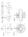
- In der Folge wird die Erfindung anhand des in den Figuren dargestellten Ausführungsbeispiels näher erläutert. Es zeigen schematisch:
- Fig. 1
- eine erste Ausführung der erfindungsgemäßen Halterung in einer Draufsicht;
- Fig. 2
- einen Schnitt nach Linie II-II in
Fig. 1 ; - Fig. 3
- einen Schnitt nach Linie III-III in
Fig. 1 ; und - Fig. 4
- eine seitliche Ansicht in montiertem Zustand.
- Die Halterung besteht aus einem ersten Isolierelement 1 und einem zweiten Isolierelement 2, die formschlüssig miteinander verbindbar sind und gemeinsam im Wesentlichen zylindrisch ausgebildet sind. Koaxial zu den beiden Isolierelementen 1, 2 ist eine Rohrleitung 3 aufgenommen, die an einem Gebäudeteil 5, wie etwa einer Zwischendecke, zu befestigen ist. In diesem Gebäudeteil 5 ist eine Aufhängung 4 eingeschraubt, die mit dem ersten Isolierelement 1 verbunden ist. Diese Verbindung erfolgt über eine an der Aufhängung 4 angebrachte Platte 6, die in einer entsprechenden Ausnehmung 7 des ersten Isolierelementes 1 aufgenommen und gehalten ist.
- Eine Schwalbenschwanzverbindung 8 sichert das zweite Isolierelement 2 formschlüssig am ersten Isolierelement 1, wobei sich der Begriff "formschlüssig" primär auf die in Gebrauchslage senkrechte Richtung bezieht. In Axialrichtung sind die beiden Isolierelemente 1, 2 gegeneinander verschiebbar. Die Teilungsebene 16 ist gegenüber der Rohrachse 17 nach unten, d.h. weg von der Halterung 4 verschoben, so dass das erste Isolierelement 1 das Rohr 3 klemmend umschließt und zumindest während der Montage in einem gewissen Ausmaß festhält, so dass bis zur Fertigstellung keine Unterstützung des Rohrs erforderlich ist.
- Nachdem der in
Fig. 1 dargestellte Zustand erreicht wird, kann das Rohr 3, das nunmehr bereits fest am Gebäude 5 angebracht ist, weiter isoliert werden, was einfach möglich ist, da lediglich zylindrische Isolierelemente zwischen die Halterungen eingefügt werden müssen. - Die beiden Isolationselemente 1, 2 sind aus PU-Schaum hergestellt, der eine Dichte von mindestens 80 kg/m3 aufweist. Für Rohre mit größerem Durchmesser oder kritischere Anwendungen sollte die Dichte mindestens 120 kg/m3 betragen.
- Die vorliegende Erfindung ermöglicht es, die Befestigung von Rohren zu vereinfachen und eine kostengünstige und thermisch vorteilhafte Lösung anzugeben.
Claims (4)
- Halterung für Rohre (3), mit einer an einem Bauwerksteil befestigbaren Aufhängung (4) und mit mindestens zwei im Wesentlichen als Halbschalen ausgebildeten Isolierelementen (1, 2), die unter Verwendung einer Schwalbenschwanzverbindung (8) formschlüssig miteinander zu einem zylindrischen Bauteil verbindbar sind, wobei die Aufhängung (4) durch eine Öffnung (9) des ersten Isolierelementes (1) hindurchgeführt ist, dadurch gekennzeichnet, dass die Aufhängung (4) das erste Isolierelement (1) mit einer Platte (6) trägt, um das Rohr ohne weiteren Haltering zu halten.
- Halterung nach Anspruch 1, dadurch gekennzeichnet, dass die Teilungsebene (16) der beiden Isolierelemente (1, 2) im Bereichs der Rohrs (3) gegenüber der Rohrachse (17) von der Aufhängung (4) weg verschoben ist.
- Halterung nach Anspruch 1 oder 2, dadurch gekennzeichnet, dass die Isolierelemente (1, 2) auf Polyurethan-Schaum aufgebaut sind.
- Halterung nach Anspruch 3, dadurch gekennzeichnet, dass der Polyurethan-Schaum der Isolierelemente (1, 2) eine Dichte aufweist, die zwischen 80 kg/m3 und 200 kg/m3 liegt.
Applications Claiming Priority (1)
| Application Number | Priority Date | Filing Date | Title |
|---|---|---|---|
| AT0112707A AT505083B1 (de) | 2007-07-17 | 2007-07-17 | Halterung für rohre |
Publications (2)
| Publication Number | Publication Date |
|---|---|
| EP2017523A1 EP2017523A1 (de) | 2009-01-21 |
| EP2017523B1 true EP2017523B1 (de) | 2010-09-15 |
Family
ID=39790016
Family Applications (1)
| Application Number | Title | Priority Date | Filing Date |
|---|---|---|---|
| EP08160571A Not-in-force EP2017523B1 (de) | 2007-07-17 | 2008-07-16 | Halterung für Rohre |
Country Status (3)
| Country | Link |
|---|---|
| EP (1) | EP2017523B1 (de) |
| AT (2) | AT505083B1 (de) |
| DE (1) | DE502008001293D1 (de) |
Families Citing this family (1)
| Publication number | Priority date | Publication date | Assignee | Title |
|---|---|---|---|---|
| AT11429U1 (de) | 2009-09-25 | 2010-10-15 | Aqotec Gmbh | Isolierungs-halbschalenkörper |
Family Cites Families (12)
| Publication number | Priority date | Publication date | Assignee | Title |
|---|---|---|---|---|
| FR862681A (fr) * | 1939-09-01 | 1941-03-12 | Cie Reunies Glaces Et Verres | Enveloppes isolantes pour tuyaux et autres corps à surface courbe |
| FR967109A (fr) * | 1948-06-01 | 1950-10-26 | Collier pour l'installation de canalisations | |
| FR92914E (fr) * | 1966-03-12 | 1969-01-17 | Metal Usine Soc Ind Du | Collier de serrage pour tubes ou objects similaires. |
| CH494915A (fr) * | 1968-02-23 | 1970-08-15 | Liber Jean Claude | Collier de fixation de canalisations, câbles électriques ou analogues |
| CH564722A5 (de) * | 1973-04-06 | 1975-07-31 | Schibig Arthur | |
| CH571675A5 (de) * | 1973-11-15 | 1976-01-15 | Ehb Ag | |
| FR2442366A1 (fr) * | 1978-11-27 | 1980-06-20 | Monnier Georges | Collier de fixation de tubes, cables, tringles et analogues sur un support quelconque |
| DE8628193U1 (de) * | 1986-10-22 | 1986-12-04 | Besloten Vennootschap met beperkte aansprakelijkheid Kunststoffenfabriek L'Insigne, Oud Alblas | Rohrklemme |
| CH672537A5 (de) * | 1987-06-03 | 1989-11-30 | Korkstein Ag | |
| US5381833A (en) * | 1992-03-18 | 1995-01-17 | Cummings; Richard | Insulated pipe assembly and pipe support therefor |
| DE9421308U1 (de) * | 1994-07-30 | 1995-08-31 | J. Van Walraven Holding B.V., Mijdrecht | Isolierung für von einer Dämmung umschlossene Rohre im Bereich der Rohrbefestigung (Fall 1) |
| DE102004053374B4 (de) * | 2004-11-02 | 2014-06-12 | Basf Se | Polyurethanhartschaumstoffe enthaltend Acrylate sowie Verfahren zu deren Herstellung |
-
2007
- 2007-07-17 AT AT0112707A patent/AT505083B1/de not_active IP Right Cessation
-
2008
- 2008-07-16 DE DE502008001293T patent/DE502008001293D1/de active Active
- 2008-07-16 AT AT08160571T patent/ATE481598T1/de active
- 2008-07-16 EP EP08160571A patent/EP2017523B1/de not_active Not-in-force
Also Published As
| Publication number | Publication date |
|---|---|
| DE502008001293D1 (de) | 2010-10-28 |
| ATE481598T1 (de) | 2010-10-15 |
| EP2017523A1 (de) | 2009-01-21 |
| AT505083B1 (de) | 2008-10-15 |
| AT505083A4 (de) | 2008-10-15 |
Similar Documents
| Publication | Publication Date | Title |
|---|---|---|
| DE102010061139A1 (de) | Adapter zur Befestigung von Gegenständen an Wänden, bei denen an der Anbauseite eine nicht tragfähige Schicht angeordnet ist | |
| DE19918153C2 (de) | Installationsbauelement | |
| AT526367B1 (de) | Verankerungselement | |
| CH678076A5 (en) | Insulating collar for reinforced concrete joints - has steel sleeves welded to one side with plastic collars on the other | |
| DE29906645U1 (de) | Durchführungs-Vorrichtung zum abgedichteten Durchführen mindestens einer Leistung durch einen in der Wand o.dgl. ausgebildeten Durchbruch | |
| EP2017523B1 (de) | Halterung für Rohre | |
| EP2122084B1 (de) | Teilesatz umfassend eine Befestigungsvorrichtung und einen Anker | |
| DE102004029910B3 (de) | Anschlussrohr, insbesondere für ein Luftführungssystem in einem Fahrzeug | |
| EP2982896A1 (de) | Hochschalldämmende rohrbefestigungsvorrichtung | |
| EP4242393B1 (de) | Verankerungselement | |
| EP0447936A2 (de) | Vorrichtung zur Befestigung von Installationselementen | |
| EP0963496B1 (de) | Fassaden-befestigungsvorrichtung | |
| DE202013002916U1 (de) | Brandschutzvorrichtung zum brandsicheren Abschotten einer Rohrverbindung | |
| EP2549167B1 (de) | Thermisch isolierende Rohrschelle | |
| EP2017522B1 (de) | Halterung für Rohre | |
| EP1278018B1 (de) | Abdeckelement | |
| DE10029475B4 (de) | Vorrichtung zur Anbringung und axialen Festlegung einer Rohrleitung | |
| DE3832399A1 (de) | Rohrhalter und verfahren zur rohrmontage mittels eines rohrhalters | |
| AT524323B1 (de) | Leitungssystem zum Zu- und/oder Ableiten zumindest eines Versorgungsmediums an eine, oder von einer Geschossebene eines Gebäudes | |
| DE19834941B4 (de) | Brandschutzvorrichtung für eine Rohrdurchführung zum Durchführen von Leitungen durch eine Montagewand aus Gipskartonplatten | |
| DE10211072B4 (de) | Halteeinrichtung für eine Leitungsvorrichtung | |
| EP4390156A1 (de) | Befestigungsverfahren eines kanals und eine vertikalbefestigung mit gewinderohr dafür | |
| EP1752669B1 (de) | Kälteschützende, feuerbeständige Verbindung | |
| DE4336964C1 (de) | Vorrichtung zur Reduzierung der Schallübertragung | |
| WO2023031208A1 (de) | Tellerankersystem zur klebenden verankerung von platten eines wandschalungssystems, wandschalungssystem, wand, verwendung eines wandschalungssystems zur herstellung eines bauwerks und verfahren zur herstellung eines bauwerks |
Legal Events
| Date | Code | Title | Description |
|---|---|---|---|
| PUAI | Public reference made under article 153(3) epc to a published international application that has entered the european phase |
Free format text: ORIGINAL CODE: 0009012 |
|
| AK | Designated contracting states |
Kind code of ref document: A1 Designated state(s): AT BE BG CH CY CZ DE DK EE ES FI FR GB GR HR HU IE IS IT LI LT LU LV MC MT NL NO PL PT RO SE SI SK TR |
|
| AX | Request for extension of the european patent |
Extension state: AL BA MK RS |
|
| 17P | Request for examination filed |
Effective date: 20090701 |
|
| AKX | Designation fees paid |
Designated state(s): AT BE BG CH CY CZ DE DK EE ES FI FR GB GR HR HU IE IS IT LI LT LU LV MC MT NL NO PL PT RO SE SI SK TR |
|
| GRAP | Despatch of communication of intention to grant a patent |
Free format text: ORIGINAL CODE: EPIDOSNIGR1 |
|
| GRAS | Grant fee paid |
Free format text: ORIGINAL CODE: EPIDOSNIGR3 |
|
| GRAA | (expected) grant |
Free format text: ORIGINAL CODE: 0009210 |
|
| AK | Designated contracting states |
Kind code of ref document: B1 Designated state(s): AT BE BG CH CY CZ DE DK EE ES FI FR GB GR HR HU IE IS IT LI LT LU LV MC MT NL NO PL PT RO SE SI SK TR |
|
| REG | Reference to a national code |
Ref country code: GB Ref legal event code: FG4D Free format text: NOT ENGLISH Ref country code: CH Ref legal event code: EP |
|
| REG | Reference to a national code |
Ref country code: IE Ref legal event code: FG4D Free format text: LANGUAGE OF EP DOCUMENT: GERMAN |
|
| REF | Corresponds to: |
Ref document number: 502008001293 Country of ref document: DE Date of ref document: 20101028 Kind code of ref document: P |
|
| REG | Reference to a national code |
Ref country code: NL Ref legal event code: VDEP Effective date: 20100915 |
|
| PG25 | Lapsed in a contracting state [announced via postgrant information from national office to epo] |
Ref country code: LT Free format text: LAPSE BECAUSE OF FAILURE TO SUBMIT A TRANSLATION OF THE DESCRIPTION OR TO PAY THE FEE WITHIN THE PRESCRIBED TIME-LIMIT Effective date: 20100915 Ref country code: NO Free format text: LAPSE BECAUSE OF FAILURE TO SUBMIT A TRANSLATION OF THE DESCRIPTION OR TO PAY THE FEE WITHIN THE PRESCRIBED TIME-LIMIT Effective date: 20101215 Ref country code: FI Free format text: LAPSE BECAUSE OF FAILURE TO SUBMIT A TRANSLATION OF THE DESCRIPTION OR TO PAY THE FEE WITHIN THE PRESCRIBED TIME-LIMIT Effective date: 20100915 |
|
| LTIE | Lt: invalidation of european patent or patent extension |
Effective date: 20100915 |
|
| PG25 | Lapsed in a contracting state [announced via postgrant information from national office to epo] |
Ref country code: SI Free format text: LAPSE BECAUSE OF FAILURE TO SUBMIT A TRANSLATION OF THE DESCRIPTION OR TO PAY THE FEE WITHIN THE PRESCRIBED TIME-LIMIT Effective date: 20100915 Ref country code: CY Free format text: LAPSE BECAUSE OF FAILURE TO SUBMIT A TRANSLATION OF THE DESCRIPTION OR TO PAY THE FEE WITHIN THE PRESCRIBED TIME-LIMIT Effective date: 20100915 Ref country code: HR Free format text: LAPSE BECAUSE OF FAILURE TO SUBMIT A TRANSLATION OF THE DESCRIPTION OR TO PAY THE FEE WITHIN THE PRESCRIBED TIME-LIMIT Effective date: 20100915 Ref country code: PL Free format text: LAPSE BECAUSE OF FAILURE TO SUBMIT A TRANSLATION OF THE DESCRIPTION OR TO PAY THE FEE WITHIN THE PRESCRIBED TIME-LIMIT Effective date: 20100915 |
|
| PG25 | Lapsed in a contracting state [announced via postgrant information from national office to epo] |
Ref country code: LV Free format text: LAPSE BECAUSE OF FAILURE TO SUBMIT A TRANSLATION OF THE DESCRIPTION OR TO PAY THE FEE WITHIN THE PRESCRIBED TIME-LIMIT Effective date: 20100915 Ref country code: SE Free format text: LAPSE BECAUSE OF FAILURE TO SUBMIT A TRANSLATION OF THE DESCRIPTION OR TO PAY THE FEE WITHIN THE PRESCRIBED TIME-LIMIT Effective date: 20100915 Ref country code: GR Free format text: LAPSE BECAUSE OF FAILURE TO SUBMIT A TRANSLATION OF THE DESCRIPTION OR TO PAY THE FEE WITHIN THE PRESCRIBED TIME-LIMIT Effective date: 20101216 |
|
| REG | Reference to a national code |
Ref country code: IE Ref legal event code: FD4D |
|
| PG25 | Lapsed in a contracting state [announced via postgrant information from national office to epo] |
Ref country code: IE Free format text: LAPSE BECAUSE OF FAILURE TO SUBMIT A TRANSLATION OF THE DESCRIPTION OR TO PAY THE FEE WITHIN THE PRESCRIBED TIME-LIMIT Effective date: 20100915 |
|
| PG25 | Lapsed in a contracting state [announced via postgrant information from national office to epo] |
Ref country code: CZ Free format text: LAPSE BECAUSE OF FAILURE TO SUBMIT A TRANSLATION OF THE DESCRIPTION OR TO PAY THE FEE WITHIN THE PRESCRIBED TIME-LIMIT Effective date: 20100915 Ref country code: RO Free format text: LAPSE BECAUSE OF FAILURE TO SUBMIT A TRANSLATION OF THE DESCRIPTION OR TO PAY THE FEE WITHIN THE PRESCRIBED TIME-LIMIT Effective date: 20100915 Ref country code: IS Free format text: LAPSE BECAUSE OF FAILURE TO SUBMIT A TRANSLATION OF THE DESCRIPTION OR TO PAY THE FEE WITHIN THE PRESCRIBED TIME-LIMIT Effective date: 20110115 Ref country code: NL Free format text: LAPSE BECAUSE OF FAILURE TO SUBMIT A TRANSLATION OF THE DESCRIPTION OR TO PAY THE FEE WITHIN THE PRESCRIBED TIME-LIMIT Effective date: 20100915 Ref country code: EE Free format text: LAPSE BECAUSE OF FAILURE TO SUBMIT A TRANSLATION OF THE DESCRIPTION OR TO PAY THE FEE WITHIN THE PRESCRIBED TIME-LIMIT Effective date: 20100915 Ref country code: PT Free format text: LAPSE BECAUSE OF FAILURE TO SUBMIT A TRANSLATION OF THE DESCRIPTION OR TO PAY THE FEE WITHIN THE PRESCRIBED TIME-LIMIT Effective date: 20110117 Ref country code: SK Free format text: LAPSE BECAUSE OF FAILURE TO SUBMIT A TRANSLATION OF THE DESCRIPTION OR TO PAY THE FEE WITHIN THE PRESCRIBED TIME-LIMIT Effective date: 20100915 Ref country code: IT Free format text: LAPSE BECAUSE OF FAILURE TO SUBMIT A TRANSLATION OF THE DESCRIPTION OR TO PAY THE FEE WITHIN THE PRESCRIBED TIME-LIMIT Effective date: 20100915 |
|
| PG25 | Lapsed in a contracting state [announced via postgrant information from national office to epo] |
Ref country code: ES Free format text: LAPSE BECAUSE OF FAILURE TO SUBMIT A TRANSLATION OF THE DESCRIPTION OR TO PAY THE FEE WITHIN THE PRESCRIBED TIME-LIMIT Effective date: 20101226 |
|
| PLBE | No opposition filed within time limit |
Free format text: ORIGINAL CODE: 0009261 |
|
| STAA | Information on the status of an ep patent application or granted ep patent |
Free format text: STATUS: NO OPPOSITION FILED WITHIN TIME LIMIT |
|
| 26N | No opposition filed |
Effective date: 20110616 |
|
| PG25 | Lapsed in a contracting state [announced via postgrant information from national office to epo] |
Ref country code: DK Free format text: LAPSE BECAUSE OF FAILURE TO SUBMIT A TRANSLATION OF THE DESCRIPTION OR TO PAY THE FEE WITHIN THE PRESCRIBED TIME-LIMIT Effective date: 20100915 |
|
| REG | Reference to a national code |
Ref country code: DE Ref legal event code: R097 Ref document number: 502008001293 Country of ref document: DE Effective date: 20110616 |
|
| PG25 | Lapsed in a contracting state [announced via postgrant information from national office to epo] |
Ref country code: MT Free format text: LAPSE BECAUSE OF FAILURE TO SUBMIT A TRANSLATION OF THE DESCRIPTION OR TO PAY THE FEE WITHIN THE PRESCRIBED TIME-LIMIT Effective date: 20100915 |
|
| BERE | Be: lapsed |
Owner name: MIKL, JOSEF Effective date: 20110731 |
|
| PG25 | Lapsed in a contracting state [announced via postgrant information from national office to epo] |
Ref country code: MC Free format text: LAPSE BECAUSE OF NON-PAYMENT OF DUE FEES Effective date: 20110731 |
|
| REG | Reference to a national code |
Ref country code: FR Ref legal event code: ST Effective date: 20120330 |
|
| PG25 | Lapsed in a contracting state [announced via postgrant information from national office to epo] |
Ref country code: BE Free format text: LAPSE BECAUSE OF NON-PAYMENT OF DUE FEES Effective date: 20110731 Ref country code: FR Free format text: LAPSE BECAUSE OF NON-PAYMENT OF DUE FEES Effective date: 20110801 |
|
| PGFP | Annual fee paid to national office [announced via postgrant information from national office to epo] |
Ref country code: DE Payment date: 20120629 Year of fee payment: 5 |
|
| REG | Reference to a national code |
Ref country code: CH Ref legal event code: PL |
|
| GBPC | Gb: european patent ceased through non-payment of renewal fee |
Effective date: 20120716 |
|
| PG25 | Lapsed in a contracting state [announced via postgrant information from national office to epo] |
Ref country code: GB Free format text: LAPSE BECAUSE OF NON-PAYMENT OF DUE FEES Effective date: 20120716 Ref country code: LI Free format text: LAPSE BECAUSE OF NON-PAYMENT OF DUE FEES Effective date: 20120731 Ref country code: CH Free format text: LAPSE BECAUSE OF NON-PAYMENT OF DUE FEES Effective date: 20120731 |
|
| PG25 | Lapsed in a contracting state [announced via postgrant information from national office to epo] |
Ref country code: LU Free format text: LAPSE BECAUSE OF NON-PAYMENT OF DUE FEES Effective date: 20110716 |
|
| PG25 | Lapsed in a contracting state [announced via postgrant information from national office to epo] |
Ref country code: BG Free format text: LAPSE BECAUSE OF FAILURE TO SUBMIT A TRANSLATION OF THE DESCRIPTION OR TO PAY THE FEE WITHIN THE PRESCRIBED TIME-LIMIT Effective date: 20101215 Ref country code: TR Free format text: LAPSE BECAUSE OF FAILURE TO SUBMIT A TRANSLATION OF THE DESCRIPTION OR TO PAY THE FEE WITHIN THE PRESCRIBED TIME-LIMIT Effective date: 20100915 |
|
| PG25 | Lapsed in a contracting state [announced via postgrant information from national office to epo] |
Ref country code: HU Free format text: LAPSE BECAUSE OF FAILURE TO SUBMIT A TRANSLATION OF THE DESCRIPTION OR TO PAY THE FEE WITHIN THE PRESCRIBED TIME-LIMIT Effective date: 20100915 |
|
| PG25 | Lapsed in a contracting state [announced via postgrant information from national office to epo] |
Ref country code: DE Free format text: LAPSE BECAUSE OF NON-PAYMENT OF DUE FEES Effective date: 20140201 |
|
| REG | Reference to a national code |
Ref country code: DE Ref legal event code: R119 Ref document number: 502008001293 Country of ref document: DE Effective date: 20140201 |
|
| REG | Reference to a national code |
Ref country code: AT Ref legal event code: MM01 Ref document number: 481598 Country of ref document: AT Kind code of ref document: T Effective date: 20130716 |
|
| PG25 | Lapsed in a contracting state [announced via postgrant information from national office to epo] |
Ref country code: AT Free format text: LAPSE BECAUSE OF NON-PAYMENT OF DUE FEES Effective date: 20130716 |