EP3885193B1 - Straddled vehicle - Google Patents
Straddled vehicle Download PDFInfo
- Publication number
- EP3885193B1 EP3885193B1 EP21157854.7A EP21157854A EP3885193B1 EP 3885193 B1 EP3885193 B1 EP 3885193B1 EP 21157854 A EP21157854 A EP 21157854A EP 3885193 B1 EP3885193 B1 EP 3885193B1
- Authority
- EP
- European Patent Office
- Prior art keywords
- light
- vehicle
- headlight
- cover
- regard
- Prior art date
- Legal status (The legal status is an assumption and is not a legal conclusion. Google has not performed a legal analysis and makes no representation as to the accuracy of the status listed.)
- Active
Links
- 238000005192 partition Methods 0.000 description 3
- 230000003287 optical effect Effects 0.000 description 2
- 239000011347 resin Substances 0.000 description 2
- 229920005989 resin Polymers 0.000 description 2
- 239000004925 Acrylic resin Substances 0.000 description 1
- 229920000178 Acrylic resin Polymers 0.000 description 1
- 230000015556 catabolic process Effects 0.000 description 1
- 238000002485 combustion reaction Methods 0.000 description 1
- 238000006731 degradation reaction Methods 0.000 description 1
- 230000001419 dependent effect Effects 0.000 description 1
- 238000007493 shaping process Methods 0.000 description 1
- 239000012780 transparent material Substances 0.000 description 1
Images


Classifications
-
- B—PERFORMING OPERATIONS; TRANSPORTING
- B60—VEHICLES IN GENERAL
- B60Q—ARRANGEMENT OF SIGNALLING OR LIGHTING DEVICES, THE MOUNTING OR SUPPORTING THEREOF OR CIRCUITS THEREFOR, FOR VEHICLES IN GENERAL
- B60Q1/00—Arrangement of optical signalling or lighting devices, the mounting or supporting thereof or circuits therefor
- B60Q1/0029—Spatial arrangement
- B60Q1/0035—Spatial arrangement relative to the vehicle
-
- B—PERFORMING OPERATIONS; TRANSPORTING
- B60—VEHICLES IN GENERAL
- B60Q—ARRANGEMENT OF SIGNALLING OR LIGHTING DEVICES, THE MOUNTING OR SUPPORTING THEREOF OR CIRCUITS THEREFOR, FOR VEHICLES IN GENERAL
- B60Q1/00—Arrangement of optical signalling or lighting devices, the mounting or supporting thereof or circuits therefor
- B60Q1/0029—Spatial arrangement
- B60Q1/0041—Spatial arrangement of several lamps in relation to each other
-
- B—PERFORMING OPERATIONS; TRANSPORTING
- B62—LAND VEHICLES FOR TRAVELLING OTHERWISE THAN ON RAILS
- B62J—CYCLE SADDLES OR SEATS; AUXILIARY DEVICES OR ACCESSORIES SPECIALLY ADAPTED TO CYCLES AND NOT OTHERWISE PROVIDED FOR, e.g. ARTICLE CARRIERS OR CYCLE PROTECTORS
- B62J6/00—Arrangement of optical signalling or lighting devices on cycles; Mounting or supporting thereof; Circuits therefor
- B62J6/02—Headlights
- B62J6/022—Headlights specially adapted for motorcycles or the like
- B62J6/026—Headlights specially adapted for motorcycles or the like characterised by the structure, e.g. casings
-
- F—MECHANICAL ENGINEERING; LIGHTING; HEATING; WEAPONS; BLASTING
- F21—LIGHTING
- F21S—NON-PORTABLE LIGHTING DEVICES; SYSTEMS THEREOF; VEHICLE LIGHTING DEVICES SPECIALLY ADAPTED FOR VEHICLE EXTERIORS
- F21S43/00—Signalling devices specially adapted for vehicle exteriors, e.g. brake lamps, direction indicator lights or reversing lights
- F21S43/20—Signalling devices specially adapted for vehicle exteriors, e.g. brake lamps, direction indicator lights or reversing lights characterised by refractors, transparent cover plates, light guides or filters
- F21S43/26—Refractors, transparent cover plates, light guides or filters not provided in groups F21S43/235 - F21S43/255
-
- B—PERFORMING OPERATIONS; TRANSPORTING
- B62—LAND VEHICLES FOR TRAVELLING OTHERWISE THAN ON RAILS
- B62K—CYCLES; CYCLE FRAMES; CYCLE STEERING DEVICES; RIDER-OPERATED TERMINAL CONTROLS SPECIALLY ADAPTED FOR CYCLES; CYCLE AXLE SUSPENSIONS; CYCLE SIDE-CARS, FORECARS, OR THE LIKE
- B62K2202/00—Motorised scooters
Definitions
- the present invention relates to a straddled vehicle.
- straddled vehicle including a position light and a headlight.
- a position light is disposed in the vicinity of a headlight.
- the position light extends from a middle portion of a front cover to be narrowly elongated in both obliquely upward directions.
- the position light includes an outer lens, light guiding members, and subordinate lighting bodies.
- the light guiding members are disposed behind the outer lens and guide light emitted from the subordinate lighting bodies.
- Another straddle type vehicle with the features of the preamble of claim 1 is shown in JP 2017-224445A .
- the position light if narrowly shaped, exerts low distinguishability when disposed near the headlight as described above.
- the light guides are required to be widely shaped as well. This results in enlargement of light sources.
- LEDs light-emitting diodes
- the LEDs are narrow in directivity.
- a large number of LEDs are required when used for such an elongated position light as described above.
- a straddled vehicle includes a head pipe, a steering device, a front wheel, a front cover, and a headlight unit.
- the steering device is turnably supported by the head pipe.
- the front wheel is rotatably supported by the steering device.
- the front cover is disposed in front of the head pipe.
- the headlight unit is disposed in the front cover.
- the headlight unit includes a headlight portion, a first position light portion, a housing, and a clear cover.
- the housing holds the headlight portion and the first position light portion.
- the clear cover is disposed in front of the headlight portion and the first position light portion.
- the clear cover allows light to transmit therethrough.
- the first position light portion is disposed above the headlight portion.
- the first position light portion includes a light source, a first light guide, and a first light diffuser.
- the first light guide is disposed behind the clear cover.
- the first light guide extends along a longitudinal direction of the clear cover.
- the first light guide guides light emitted from the light source.
- the first light diffuser is disposed behind the clear cover and in front of the first light guide.
- the first light diffuser extends along the longitudinal direction of the clear cover.
- the first light diffuser have a greater width than the first light guide.
- the light emitted from the light source is guided by the first light guide. Because of this, even when the first position light portion has an elongated shape, the light source can be inhibited from being increased in number. Moreover, the light emitted from the first light guide is diffused by the first light diffuser having the greater width than the first light guide. Accordingly, the light source and the first light guide can be inhibited from being enlarged, and simultaneously, the first position light portion can be enhanced in distinguishability.
- the first position light portion may further include a light shading portion dividing right and left the first light diffuser.
- the first position light portion appears as if it were composed of a plurality of position lights. Because of this, the first position light portion can be enhanced in distinguishability.
- the first position light portion may adjoin an upper edge of the headlight portion.
- the headlight unit can be made compact. Besides, even when the first position light portion adjoins the headlight portion, degradation in distinguishability of the first position light portion can be inhibited by both the first light guide and the first light diffuser described above.
- the headlight portion may include a first headlight portion and a second headlight portion.
- the first headlight portion may extend leftward and obliquely upward from a middle portion of the front cover.
- the second headlight portion may extend rightward and obliquely upward from the middle portion of the front cover.
- the first position light portion may be disposed above the first headlight portion.
- the headlight unit may further include a second position light portion.
- the second position light portion may be disposed above the second headlight portion. In this case, the position light portions can be further enhanced in distinguishability by the first and second position light portions.
- the second position light portion may include a second light guide and a second light diffuser.
- the second light guide may be disposed behind the clear cover.
- the second light guide may extend along the longitudinal direction of the clear cover.
- the second light diffuser may be disposed behind the clear cover and in front of the second light guide.
- the second light diffuser may extend along the longitudinal direction of the clear cover and may have a greater width than the second light guide. In this case, the light source and the second light guide can be inhibited from being enlarged, and simultaneously, the second position light portion can be enhanced in distinguishability.
- the light source may be disposed between the first light guide and the second light guide.
- the first and second position light portions can be lit up by the light source shared therebetween. Accordingly, the light source can be further inhibited from being enlarged and increased in number.
- the first headlight portion may include a first inner light and a first outer light.
- the first inner light may include a first inner light source.
- the first outer light may include a first outer light source.
- the first outer light may be disposed on a left side of the first inner light.
- the second headlight portion may include a second inner light and a second outer light.
- the second inner light may include a second inner light source.
- the second outer light may include a second outer light source.
- the second outer light may be disposed on a right side of the second inner light. In this case, a range of light emitted by the first and second headlight portions can be extended.
- the first inner light and the second inner light may be low-beam lights.
- the first outer light and the second outer light may be high-beam lights.
- FIG. 1 is a side view of a straddled vehicle 1 according to the embodiment.
- the straddled vehicle 1 according to the present embodiment is a scooter-type vehicle.
- the straddled vehicle 1 includes a vehicle body frame 2, a steering device 3, a front wheel 4, a seat 5, a power unit 6, and a rear wheel 7.
- front and rear with regard to a front-and-rear direction of the vehicle right and left with regard to a right-and-left direction of the vehicle, above and below with regard to an up-and-down direction of the vehicle are defined as indicating front, rear, right, left, upward and downward directions seen from a driver seated on the seat 5.
- the vehicle body frame 2 includes a head pipe 11, a down frame 12, a lower frame 13 and a rear frame 14.
- the head pipe 11 is disposed in the middle of the vehicle in a right-and-left direction.
- the head pipe 11 extends forward and downward.
- the down frame 12 extends downward from the head pipe 11.
- the lower frame 13 extends backward from a lower portion of the down frame 12.
- the rear frame 14 extends backward and upward from a rear portion of the down frame 12.
- the steering device 3 is supported by the head pipe 11 so as to be turnable.
- the steering device 3 supports the front wheel 4 such that the front wheel 4 is rotatable.
- the steering device 3 includes a front fork 16 and a handle member 17.
- the front fork 16 is supported by the head pipe 11 so as to be turnable.
- the front wheel 4 is supported by the front fork 16 so as to be rotatable.
- the handle member 17 can be operated by the driver in order to turn the front wheel 4.
- the handle member 17 extends in the right-and-left direction.
- the seat 5 is disposed behind the head pipe 11.
- the seat 5 is disposed above the rear frame 14.
- the power unit 6 is disposed below the seat 5.
- the power unit 6 includes, for instance, an internal combustion engine. Alternatively, the power unit 6 may include an electric motor.
- the rear wheel 7 is supported by the power unit 6 so as to be rotatable.
- the straddled vehicle 1 includes a front cover 21, a leg shield 22, a side cover 23, and a handle cover 24.
- the front cover 21 is fixed to the vehicle body frame 2.
- the front cover 21 is disposed in front of the head pipe 11.
- FIG. 2 is a front view of the front cover 21. As shown in FIG. 2 , the front cover 21 overlaps the head pipe 11 as seen in a vehicle front view.
- the leg shield 22 is disposed behind the front cover 21.
- the side cover 23 is disposed below the seat 5.
- the side cover 23 covers the rear frame 14 from lateral sides.
- the side cover 23 is disposed between the leg shield 22 and the seat 5.
- the handle cover 24 covers part of the handle member 17.
- the handle cover 24 is located above the front cover 21.
- the handle cover 24 is located above the head pipe 11.
- the handle cover 24 is turnable together with the handle member 17 with respect to the front cover 21.
- the straddled vehicle 1 includes a headlight unit 30.
- the headlight unit 30 is disposed in the front cover 21.
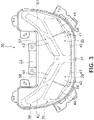
- FIG. 3 is a front view of the headlight unit 30.
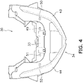
- FIG. 4 is a top view of the headlight unit 30.
- the headlight unit 30 includes a headlight portion 31, a position light portion 32, a housing 33, and a clear cover 34.
- the housing 33 is disposed behind the headlight portion 31 and the position light portion 32.
- the housing 33 holds the headlight portion 31 and the position light portion 32.
- the clear cover 34 is disposed in front of the headlight portion 31 and the position light portion 32.
- the clear cover 34 is made of transparent material and allows light to transmit therethrough.
- the headlight portion 31 includes a first headlight portion 35 and a second headlight portion 36.
- the first headlight portion 35 is disposed leftward of the center of the vehicle in the right-and-left direction. As seen in the vehicle front view, the first headlight portion 35 extends leftward and obliquely upward from a middle portion of the front cover 21 in the right-and-left direction.
- the second headlight portion 36 is disposed rightward of the center of the vehicle in the right-and-left direction. As seen in the vehicle front view, the second headlight portion 36 extends rightward and obliquely upward from the middle portion of the front cover 21 in the right-and-left direction.
- the position light portion 32 is disposed above the headlight portion 31.
- the position light portion 32 includes a first position light portion 37 and a second position light portion 38.
- the first position light portion 37 is disposed above the first headlight portion 35. As shown in FIG. 2 , the first position light portion 37 adjoins an upper edge 351 of the first headlight portion 35. The first position light portion 37 extends along the upper edge 351 of the first headlight portion 35.
- the second position light portion 38 is disposed above the second headlight portion 36. The second position light portion 38 adjoins an upper edge 361 of the second headlight portion 36. The second position light portion 38 extends along the upper edge 361 of the second headlight portion 36.
- the first position light portion 37 extends to a position leftward of the first headlight portion 35.
- an outer lateral end 371 of the first position light portion 37 is located laterally outside an outer lateral end 352 of the first headlight portion 35.
- the second position light portion 38 extends to a position rightward of the second headlight portion 36.
- an outer lateral end 381 of the second position light portion 38 is located laterally outside an outer lateral end 362 of the second headlight portion 36.
- the clear cover 34 includes a first headlight cover 41, a second headlight cover 42, a first position light cover 43, and a second position light cover 44.
- the first headlight cover 41 is disposed in front of the first headlight portion 35. As seen in the vehicle front view, the first headlight cover 41 overlaps the first headlight portion 35.
- the second headlight cover 42 is disposed in front of the second headlight portion 36. As seen in the vehicle front view, the second headlight cover 42 overlaps the second headlight portion 36.
- the first position light cover 43 is disposed in front of the first position light portion 37. As seen in the vehicle front view, the first position light cover 43 overlaps the first position light portion 37.
- the second position light cover 44 is disposed in front of the second position light portion 38. As seen in the vehicle front view, the second position light cover 44 overlaps the second position light portion 38.
- the first headlight cover 41, the second headlight cover 42, the first position light cover 43, and the second position light cover 44 are integrally provided.
- the front cover 21 includes a headlight opening 25.
- the headlight unit 30 is exposed outside through the headlight opening 25.
- the headlight opening 25 includes a first opening 26 and a second opening 27.
- the first headlight portion 35 and the first position light portion 37 are exposed outside through the first opening 26.
- the second headlight portion 36 and the second position light portion 38 are exposed outside through the second opening 27.
- the front cover 21 includes an upper protruding portion 211 and a lower protruding portion 212.
- the upper protruding portion 211 protrudes downward from the upper edge of the headlight opening 25.
- the lower protruding portion 212 protrudes upward from the lower edge of the headlight opening 25.
- the upper and lower protruding portions 211 and 212 are connected to each other.
- the upper and lower protruding portions 211 and 212 overlap the clear cover 34.
- the upper and lower protruding portions 211 and 212 are located between the first and second openings 26 and 27.
- the upper and lower protruding portions 211 and 212 divide the headlight opening 25 into the first and second openings 26 and 27.
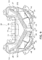
- FIG. 5 is a front view of the headlight unit 30 that the clear cover 34 is detached.
- the first headlight portion 35 includes a first inner light 45 and a first outer light 46.
- the first outer light 46 is disposed on the left side of the first inner light 45.
- the second headlight portion 36 includes a second inner light 47 and a second outer light 48.
- the second outer light 48 is disposed on the right side of the second inner light 47.
- the first inner light 45 includes a first inner light source 49.
- the first outer light 46 includes a first outer light source 50.
- the second inner light 47 includes a second inner light source 51.
- the second outer light 48 includes a second outer light source 52.
- the first and second inner light sources 49 and 51 and the first and second outer light sources 50 and 52 are, for instance, light-emitting diodes (LEDs).
- the first and second inner light sources 49 and 51 and the first and second outer light sources 50 and 52 may be light bulbs.
- the first inner light 45 includes a first inner reflector 53.
- the first inner reflector 53 reflects light emitted from the first inner light source 49.
- the first outer light 46 includes a first outer reflector 54.
- the first outer reflector 54 reflects light emitted from the first outer light source 50.
- the second inner light 47 includes a second inner reflector 55.
- the second inner reflector 55 reflects light emitted from the second inner light source 51.
- the second outer light 48 includes a second outer reflector 56.
- the second outer reflector 56 reflects light emitted from the second outer light source 52.
- the first and second inner lights 45 and 47 are disposed inside the first and second outer lights 46 and 48 in the right-and-left direction of the vehicle.
- the first and second inner lights 45 and 47 are divided from each other through a middle partition 57.
- the first outer light 46 and the first inner light 45 are divided from each other through a first partition 58.
- the second outer light 48 and the second inner light 47 are divided from each other through a second partition 59.
- the first and second inner lights 45 and 47 are low-beam lights.
- the first and second outer lights 46 and 48 are high-beam lights.
- the optical axis of the first outer light source 50 is oriented more upward than that of the first inner light source 49.
- the optical axis of the second outer light source 52 is oriented more upward than that of the second inner light source 51.
- the position light portion 32 includes an inner cover 60, a first light diffuser 61, and a second light diffuser 62.
- the inner cover 60 and the first and second light diffusers 61 and 62 are disposed behind the clear cover 34.
- the inner cover 60 is disposed in front of the first and second light diffusers 61 and 62.
- the inner cover 60 covers part of the first and second light diffusers 61 and 62 from ahead.
- the inner cover 60 includes a first cover portion 63 and a second cover portion 64.
- the first and second cover portions 63 and 64 are integrally provided. As seen in the vehicle front view, the first cover portion 63 overlaps part of the first light diffuser 61.
- the second cover portion 64 overlaps part of the second light diffuser 62.
- the first cover portion 63 and the first light diffuser 61 are included in the first position light portion 37.
- the second cover portion 64 and the second light diffuser 62 are included in the second position light portion 38.
- the first and second light diffusers 61 and 62 are separated from each other.
- the first light diffuser 61 extends along a longitudinal direction of the first position light cover 43.
- the second light diffuser 62 extends along a longitudinal direction of the second position light cover 44.
- the first light diffuser 61 extends leftward and obliquely upward from a middle portion of the headlight unit 30.
- the second light diffuser 62 extends rightward and obliquely upward from the middle portion of the headlight unit 30.
- the first light diffuser 61 extends to a position leftward of the first headlight portion 35.
- an outer lateral end 611 of the first light diffuser 61 is located laterally outside the outer lateral end 352 of the first headlight portion 35.
- the second light diffuser 62 extends to a position rightward of the second headlight portion 36.
- an outer lateral end 621 of the second light diffuser 62 is located laterally outside the outer lateral end 362 of the second headlight portion 36.
- the first and second light diffusers 61 and 62 are made of, for instance, light diffusive resin.
- the first light diffuser 61 allows light, incident thereinto from behind, to forwardly transmit therethrough in a diffused manner.
- the second light diffuser 62 allows light, incident thereinto from behind, to forwardly transmit therethrough in a diffused manner.
- the first cover portion 63 includes a first inner opening 65, a first outer opening 66, and a first light shading portion 67.
- the first inner opening 65 is disposed above the first inner light 45.
- the first outer opening 66 is disposed on the left side of the first inner opening 65.
- the first outer opening 66 is disposed above the first outer light 46.
- FIG. 6 is a cross-sectional view of FIG. 5 taken along line VI-VI. As shown in FIG. 6 , the first light diffuser 61 is forwardly exposed from the first cover portion 63 through the first inner opening 65.
- FIG. 7 is a cross-sectional view of FIG. 5 taken along line VII-VII. As shown in FIG. 7 , the first light diffuser 61 is forwardly exposed from the first cover portion 63 through the first outer opening 66.
- the first light shading portion 67 is disposed between the first inner opening 65 and the first outer opening 66. As seen in the vehicle front view, the first light shading portion 67 extends leftward and obliquely upward. As seen in the vehicle front view, the first light shading portion 67 overlaps the first light diffuser 61. The first light shading portion 67 divides right and left the first light diffuser 61.
- FIG. 8 is a cross-sectional view of FIG. 5 taken along line VIII-VIII. As shown in FIG. 8 , the first light diffuser 61 includes a first recessed portion 68. The first recessed portion 68 is recessed backward from the front surface of the first light diffuser 61. The first recessed portion 68 is disposed in opposition to the first light shading portion 67. The first light shading portion 67 is at least in part disposed within the first recessed portion 68.
- the second cover portion 64 has a structure bilaterally symmetric to that of the first cover portion 63.
- the second cover portion 64 includes a second inner opening 69, a second outer opening 70, and a second light shading portion 71.
- the second inner opening 69 is disposed above the second inner light 47.
- the second outer opening 70 is disposed on the right side of the second inner opening 69.
- the second outer opening 70 is disposed above the second outer light 48.
- the second light diffuser 62 is forwardly exposed from the second cover portion 64 through the second inner opening 69.
- the second light diffuser 62 is forwardly exposed from the second cover portion 64 through the second outer opening 70.
- the second light shading portion 71 is disposed between the second inner opening 69 and the second outer opening 70. As seen in the vehicle front view, the second light shading portion 71 extends rightward and obliquely upward. As seen in the vehicle front view, the second light shading portion 71 overlaps the second light diffuser 62. The second light shading portion 71 divides right and left the second light diffuser 62.
- FIG. 9 is a front view of the headlight unit 30 that the inner cover 60, the first light diffuser 61, and the second light diffuser 62 are detached.
- the position light portion 32 includes a support member 72, a first light guide 73, a second light guide 74, and a light source 75.
- the support member 72 is disposed behind the inner cover 60.
- the support member 72 is disposed in front of the housing 33.
- the support member 72 supports the first light guide 73, the second light guide 74, and the light source 75.
- the support member 72 is disposed behind the first and second light guides 73 and 74.
- the support member 72 includes a first support portion 76 and a second support portion 77.
- the first and second support portions 76 and 77 are integrally provided.
- the first support portion 76 supports the first light guide 73.
- the second support portion 77 supports the second light guide 74.
- the first support portion 76 and the first light guide 73 are included in the first position light portion 37.
- the second support portion 77 and the second light guide 74 are included in the second position light portion 38.
- the first and second light guides 73 and 74 are separated from each other.
- the first light guide 73 extends along the longitudinal direction of the first position light cover 43.
- the second light guide 74 extends along the longitudinal direction of the second position light cover 44.
- the first light guide 73 extends leftward and obliquely upward from the middle portion of the headlight unit 30.
- the second light guide 74 extends rightward and obliquely upward from the middle portion of the headlight unit 30.
- the first light guide 73 extends to a position leftward of the first headlight portion 35.
- an outer lateral end 731 of the first light guide 73 is located laterally outside the outer lateral end 352 of the first headlight portion 35.
- the second light guide 74 extends to a position rightward of the second headlight portion 36.
- an outer lateral end 741 of the second light guide 74 is located laterally outside the outer lateral end 362 of the second headlight portion 36.
- the light source 75 is shared between the first and second position light portions 37 and 38.
- the light source 75 is, for instance, an LED.
- the light source 75 may be a light bulb.
- the light source 75 is disposed between the first and second light guides 73 and 74.
- the light source 75 is disposed in opposition to one end of the first light guide 73.
- the light source 75 is disposed in opposition to one end of the second light guide 74.
- the first and second light guides 73 and 74 are each made of, for instance, resin such as acrylic resin.
- the first and second light guides 73 and 74 are each processed to reflect light in the interior thereof.
- the first light guide 73 entirely emits light, while guiding light emitted from the light source 75 in the longitudinal direction of the first light guide 73.
- the second light guide 74 entirely emits light, while guiding the light emitted from the light source 75 in the longitudinal direction of the second light guide 74.
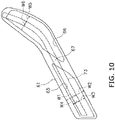
- FIG. 10 is a front view of the first light diffuser 61 and the first light guide 73.
- the first light diffuser 61 overlaps the first light guide 73.
- the first light diffuser 61 overlaps the entirety of the first light guide 73.
- the first light diffuser 61 may overlap part of the first light guide 73.
- the first light guide 73 is shaped to be narrower than the first light diffuser 61.
- the first light diffuser 61 has a width W2 greater than a width W1 of the first light guide 73.
- W2 means a dimension in a perpendicular direction to a tangent line of the upper or lower edge of the first light diffuser 61 as seen in the vehicle front view.
- width may mean a dimension in a perpendicular direction to a tangent line of the upper or lower edge of the first light guide 73 as seen in the vehicle front view.
- the term “width” may mean a dimension in the vehicle up-and-down direction as seen in the vehicle front view.
- the first light guide 73 has a width W4 less than a width W3 of the first inner opening 65 at least in a range thereof overlapping the first inner opening 65.
- the first light guide 73 has a width W6 less than a width W5 of the first outer opening 66 at least in a range overlapping the first outer opening 66.
- the second light diffuser 62 is disposed in front of the second light guide 74.
- FIG. 11 is a front view of the second light diffuser 62 and the second light guide 74. As seen in the vehicle front view shown in FIG. 11 , the second light diffuser 62 overlaps the second light guide 74. As seen in the vehicle front view, the second light diffuser 62 overlaps the entirety of the second light guide 74. Alternatively, as seen in the vehicle front view, the second light diffuser 62 may overlap part of the second light guide 74.
- the second light guide 74 is shaped to be narrower than the second light diffuser 62. In other words, the second light diffuser 62 has a width W12 greater than a width W11 of the second light guide 74.
- the second light guide 74 has a width W14 less than a width W13 of the second inner opening 69 at least in a range thereof overlapping the second inner opening 69.
- the second light guide 74 has a width W16 less than a width 15 of the second outer opening 70 at least in a range thereof overlapping the second outer opening 70.
- the light emitted from the light source 75 is guided by the first light guide 73. Because of this, even when the first position light portion 37 has an elongated shape, the light source 75 is inhibited from being increased in number. Moreover, the light emitted from the first light guide 73 is diffused by the first light diffuser 61 having the greater width than the first light guide 73. Accordingly, the light source 75 and the first light guide 73 can be inhibited from being enlarged, and simultaneously, the first position light portion 37 can be enhanced in distinguishability. As is the same with the first position light portion 37, the second position light portion 38 can be also enhanced in distinguishability.
- the light emitted from the first light guide 73 is diffused by the first light diffuser 61 and is then blocked at the first light shading portion 67. Because of this, as shown in FIG. 2 , in lighting up the first position light portion 37, the light of the first position light portion 37 is divided right and left, while being shaded at the position of the first light shading portion 67. Accordingly, the first position light portion 37 appears as if it were composed of a plurality of lights. Because of this, the first position light portion 37 can be enhanced in distinguishability without increasing the number of light sources. As is the same with the first position light portion 37, the second position light portion 38 can be also enhanced in distinguishability.
- the straddled vehicle 1 is not limited to the scooter-type vehicle, and alternatively, may be another type of vehicle such as a moped.
- the structure of the straddled vehicle 1 is not limited to that in the embodiment described above and may be changed.
- the straddled vehicle 1 may have a structure with a flat footboard provided between the seat 5 and the leg shield 22.
- the flat footboard may be entirely flat in the right-and-left direction of the straddled vehicle 1.
- the number of front wheels is not limited to one, and alternatively, may be greater than one.
- the number of rear wheels is not limited to one, and alternatively, may be greater than one.
- the structure of the vehicle body frame 2 is not limited to that in the embodiment described above and may be changed.
- the shape of the down frame 12, the lower frame 13, or the rear frame 14 may be changed.
- the structure of the front cover 21 is not limited to that in the embodiment described above and may be changed.
- the structure of the headlight unit 30 is not limited to that in the embodiment described above and may be changed.
- the layout of the high-beam lights and the low-beam lights may be changed from that described above.
- the clear cover 34 is not limited to an integrated member.
- the housing 33 is not limited to an integrated member, and alternatively, may be divided into a plurality of members.
- the first and second cover portions 63 and 64 may be separated from each other.
- the first and second support portions 76 and 77 may be separated from each other.
- the structure of the position light portion 32 is not limited to that in the embodiment described above and may be changed.
- the shape or layout of the first light diffuser 61 and the first light guide 73 may be changed.
- the shape or layout of the second light diffuser 62 and the second light guide 74 may be changed.
- the light source 75 may not be shared between the first position light portion 37 and the second position light portion 38.
- a light source may be provided for each of the first and second position light portions 37 and 38.
- the shape or layout of the first and second light shading portions 67 and 71 may be changed. Alternatively, the first and second light shading portions 67 and 71 may be omitted.
Landscapes
- Engineering & Computer Science (AREA)
- Mechanical Engineering (AREA)
- General Engineering & Computer Science (AREA)
- Non-Portable Lighting Devices Or Systems Thereof (AREA)
- Lighting Device Outwards From Vehicle And Optical Signal (AREA)
Description
- The present invention relates to a straddled vehicle.
- There is a type of straddled vehicle including a position light and a headlight. For example,
PCT International Patent Application Publication No. WO2018/180352 describes that a position light is disposed in the vicinity of a headlight. The position light extends from a middle portion of a front cover to be narrowly elongated in both obliquely upward directions. The position light includes an outer lens, light guiding members, and subordinate lighting bodies. The light guiding members are disposed behind the outer lens and guide light emitted from the subordinate lighting bodies. Another straddle type vehicle with the features of the preamble ofclaim 1 is shown inJP 2017-224445A - The position light, if narrowly shaped, exerts low distinguishability when disposed near the headlight as described above. However, in widely shaping the position light, the light guides are required to be widely shaped as well. This results in enlargement of light sources.
- Incidentally, in recent years, light-emitting diodes (LEDs) have been used as light sources for position lights. However, the LEDs are narrow in directivity. Hence, a large number of LEDs are required when used for such an elongated position light as described above. This results in increase in cost of the LEDs. Besides, this results in expansion of a space for disposing the large number of LEDs and a board for attaching these LEDs.
- It is an object of the present invention to provide a straddled vehicle that can inhibit a light source from being enlarged and increased in number, and simultaneously, to enhance distinguishability of a position light. According to the present invention said object is solved by a straddled vehicle having the features of
independent claim 1. Preferred embodiments are laid down in the dependent claims. - A straddled vehicle according to an aspect of the present teaching includes a head pipe, a steering device, a front wheel, a front cover, and a headlight unit. The steering device is turnably supported by the head pipe. The front wheel is rotatably supported by the steering device. The front cover is disposed in front of the head pipe. The headlight unit is disposed in the front cover.
- The headlight unit includes a headlight portion, a first position light portion, a housing, and a clear cover. The housing holds the headlight portion and the first position light portion. The clear cover is disposed in front of the headlight portion and the first position light portion. The clear cover allows light to transmit therethrough. The first position light portion is disposed above the headlight portion. The first position light portion includes a light source, a first light guide, and a first light diffuser. The first light guide is disposed behind the clear cover. The first light guide extends along a longitudinal direction of the clear cover. The first light guide guides light emitted from the light source. The first light diffuser is disposed behind the clear cover and in front of the first light guide. The first light diffuser extends along the longitudinal direction of the clear cover. The first light diffuser have a greater width than the first light guide.
- In the straddled vehicle according to the present aspect, the light emitted from the light source is guided by the first light guide. Because of this, even when the first position light portion has an elongated shape, the light source can be inhibited from being increased in number. Moreover, the light emitted from the first light guide is diffused by the first light diffuser having the greater width than the first light guide. Accordingly, the light source and the first light guide can be inhibited from being enlarged, and simultaneously, the first position light portion can be enhanced in distinguishability.
- The first position light portion may further include a light shading portion dividing right and left the first light diffuser. In this case, the first position light portion appears as if it were composed of a plurality of position lights. Because of this, the first position light portion can be enhanced in distinguishability.
- The first position light portion may adjoin an upper edge of the headlight portion. In this case, the headlight unit can be made compact. Besides, even when the first position light portion adjoins the headlight portion, degradation in distinguishability of the first position light portion can be inhibited by both the first light guide and the first light diffuser described above.
- The headlight portion may include a first headlight portion and a second headlight portion. The first headlight portion may extend leftward and obliquely upward from a middle portion of the front cover. The second headlight portion may extend rightward and obliquely upward from the middle portion of the front cover. The first position light portion may be disposed above the first headlight portion. The headlight unit may further include a second position light portion. The second position light portion may be disposed above the second headlight portion. In this case, the position light portions can be further enhanced in distinguishability by the first and second position light portions.
- The second position light portion may include a second light guide and a second light diffuser. The second light guide may be disposed behind the clear cover. The second light guide may extend along the longitudinal direction of the clear cover. The second light diffuser may be disposed behind the clear cover and in front of the second light guide. The second light diffuser may extend along the longitudinal direction of the clear cover and may have a greater width than the second light guide. In this case, the light source and the second light guide can be inhibited from being enlarged, and simultaneously, the second position light portion can be enhanced in distinguishability.
- The light source may be disposed between the first light guide and the second light guide. In this case, the first and second position light portions can be lit up by the light source shared therebetween. Accordingly, the light source can be further inhibited from being enlarged and increased in number.
- The first headlight portion may include a first inner light and a first outer light. The first inner light may include a first inner light source. The first outer light may include a first outer light source. The first outer light may be disposed on a left side of the first inner light. The second headlight portion may include a second inner light and a second outer light. The second inner light may include a second inner light source. The second outer light may include a second outer light source. The second outer light may be disposed on a right side of the second inner light. In this case, a range of light emitted by the first and second headlight portions can be extended.
- The first inner light and the second inner light may be low-beam lights. The first outer light and the second outer light may be high-beam lights.
-
-
FIG. 1 is a side view of a straddled vehicle according to an embodiment. -
FIG. 2 is a front view of a front cover. -
FIG. 3 is a front view of a headlight unit. -
FIG. 4 is a top view of the headlight unit. -
FIG. 5 is a front view of the headlight unit that a clear cover is detached. -
FIG. 6 is a cross-sectional view ofFIG. 5 taken along line VI-VI. -
FIG. 7 is a cross-sectional view ofFIG. 5 taken along line VII-VII. -
FIG. 8 is a cross-sectional view ofFIG. 5 taken along line VIII-VIII. -
FIG. 9 is a front view of the headlight unit that an inner cover, a first light diffuser, and a second light diffuser are detached. -
FIG. 10 is a front view of the first light diffuser and a first light guide. -
FIG. 11 is a front view of the second light diffuser and a second light guide. - A straddled vehicle according to an embodiment of the present teaching will be hereinafter explained with reference to drawings.
FIG. 1 is a side view of a straddledvehicle 1 according to the embodiment. The straddledvehicle 1 according to the present embodiment is a scooter-type vehicle. As shown inFIG. 1 , the straddledvehicle 1 includes avehicle body frame 2, asteering device 3, afront wheel 4, aseat 5, apower unit 6, and arear wheel 7. It should be noted that in the following explanation, front and rear with regard to a front-and-rear direction of the vehicle, right and left with regard to a right-and-left direction of the vehicle, above and below with regard to an up-and-down direction of the vehicle are defined as indicating front, rear, right, left, upward and downward directions seen from a driver seated on theseat 5. - The
vehicle body frame 2 includes ahead pipe 11, adown frame 12, alower frame 13 and arear frame 14. Thehead pipe 11 is disposed in the middle of the vehicle in a right-and-left direction. Thehead pipe 11 extends forward and downward. The downframe 12 extends downward from thehead pipe 11. Thelower frame 13 extends backward from a lower portion of thedown frame 12. Therear frame 14 extends backward and upward from a rear portion of thedown frame 12. - The
steering device 3 is supported by thehead pipe 11 so as to be turnable. Thesteering device 3 supports thefront wheel 4 such that thefront wheel 4 is rotatable. Thesteering device 3 includes afront fork 16 and ahandle member 17. Thefront fork 16 is supported by thehead pipe 11 so as to be turnable. Thefront wheel 4 is supported by thefront fork 16 so as to be rotatable. Thehandle member 17 can be operated by the driver in order to turn thefront wheel 4. Thehandle member 17 extends in the right-and-left direction. - The
seat 5 is disposed behind thehead pipe 11. Theseat 5 is disposed above therear frame 14. Thepower unit 6 is disposed below theseat 5. Thepower unit 6 includes, for instance, an internal combustion engine. Alternatively, thepower unit 6 may include an electric motor. Therear wheel 7 is supported by thepower unit 6 so as to be rotatable. - The straddled
vehicle 1 includes afront cover 21, aleg shield 22, aside cover 23, and ahandle cover 24. Thefront cover 21 is fixed to thevehicle body frame 2. Thefront cover 21 is disposed in front of thehead pipe 11.FIG. 2 is a front view of thefront cover 21. As shown inFIG. 2 , thefront cover 21 overlaps thehead pipe 11 as seen in a vehicle front view. - As shown in
FIG. 1 , theleg shield 22 is disposed behind thefront cover 21. The side cover 23 is disposed below theseat 5. The side cover 23 covers therear frame 14 from lateral sides. The side cover 23 is disposed between theleg shield 22 and theseat 5. - The
handle cover 24 covers part of thehandle member 17. Thehandle cover 24 is located above thefront cover 21. Thehandle cover 24 is located above thehead pipe 11. Thehandle cover 24 is turnable together with thehandle member 17 with respect to thefront cover 21. - The straddled
vehicle 1 includes aheadlight unit 30. Theheadlight unit 30 is disposed in thefront cover 21.FIG. 3 is a front view of theheadlight unit 30.FIG. 4 is a top view of theheadlight unit 30. As shown inFIGS. 2 and3 , theheadlight unit 30 includes aheadlight portion 31, a positionlight portion 32, ahousing 33, and aclear cover 34. Thehousing 33 is disposed behind theheadlight portion 31 and the positionlight portion 32. Thehousing 33 holds theheadlight portion 31 and the positionlight portion 32. Theclear cover 34 is disposed in front of theheadlight portion 31 and the positionlight portion 32. Theclear cover 34 is made of transparent material and allows light to transmit therethrough. - The
headlight portion 31 includes afirst headlight portion 35 and asecond headlight portion 36. Thefirst headlight portion 35 is disposed leftward of the center of the vehicle in the right-and-left direction. As seen in the vehicle front view, thefirst headlight portion 35 extends leftward and obliquely upward from a middle portion of thefront cover 21 in the right-and-left direction. Thesecond headlight portion 36 is disposed rightward of the center of the vehicle in the right-and-left direction. As seen in the vehicle front view, thesecond headlight portion 36 extends rightward and obliquely upward from the middle portion of thefront cover 21 in the right-and-left direction. - The position
light portion 32 is disposed above theheadlight portion 31. The positionlight portion 32 includes a first positionlight portion 37 and a second positionlight portion 38. The first positionlight portion 37 is disposed above thefirst headlight portion 35. As shown inFIG. 2 , the first positionlight portion 37 adjoins anupper edge 351 of thefirst headlight portion 35. The first positionlight portion 37 extends along theupper edge 351 of thefirst headlight portion 35. The second positionlight portion 38 is disposed above thesecond headlight portion 36. The second positionlight portion 38 adjoins anupper edge 361 of thesecond headlight portion 36. The second positionlight portion 38 extends along theupper edge 361 of thesecond headlight portion 36. - As seen in the vehicle front view, the first position
light portion 37 extends to a position leftward of thefirst headlight portion 35. In other words, as seen in the vehicle front view, an outerlateral end 371 of the first positionlight portion 37 is located laterally outside an outerlateral end 352 of thefirst headlight portion 35. As seen in the vehicle front view, the second positionlight portion 38 extends to a position rightward of thesecond headlight portion 36. In other words, as seen in the vehicle front view, an outerlateral end 381 of the second positionlight portion 38 is located laterally outside an outerlateral end 362 of thesecond headlight portion 36. - As shown in
FIG. 3 , theclear cover 34 includes afirst headlight cover 41, asecond headlight cover 42, a first positionlight cover 43, and a second positionlight cover 44. Thefirst headlight cover 41 is disposed in front of thefirst headlight portion 35. As seen in the vehicle front view, thefirst headlight cover 41 overlaps thefirst headlight portion 35. Thesecond headlight cover 42 is disposed in front of thesecond headlight portion 36. As seen in the vehicle front view, thesecond headlight cover 42 overlaps thesecond headlight portion 36. The first positionlight cover 43 is disposed in front of the first positionlight portion 37. As seen in the vehicle front view, the first positionlight cover 43 overlaps the first positionlight portion 37. The second positionlight cover 44 is disposed in front of the second positionlight portion 38. As seen in the vehicle front view, the second positionlight cover 44 overlaps the second positionlight portion 38. Thefirst headlight cover 41, thesecond headlight cover 42, the first positionlight cover 43, and the second positionlight cover 44 are integrally provided. - As shown in
FIG. 2 , thefront cover 21 includes aheadlight opening 25. Theheadlight unit 30 is exposed outside through theheadlight opening 25. Theheadlight opening 25 includes afirst opening 26 and asecond opening 27. Thefirst headlight portion 35 and the first positionlight portion 37 are exposed outside through thefirst opening 26. Thesecond headlight portion 36 and the second positionlight portion 38 are exposed outside through thesecond opening 27. Thefront cover 21 includes an upper protrudingportion 211 and a lower protrudingportion 212. The upper protrudingportion 211 protrudes downward from the upper edge of theheadlight opening 25. Thelower protruding portion 212 protrudes upward from the lower edge of theheadlight opening 25. The upper and lower protrudingportions portions clear cover 34. The upper and lower protrudingportions second openings portions headlight opening 25 into the first andsecond openings -
FIG. 5 is a front view of theheadlight unit 30 that theclear cover 34 is detached. As shown inFIG. 5 , thefirst headlight portion 35 includes a firstinner light 45 and a firstouter light 46. The firstouter light 46 is disposed on the left side of the firstinner light 45. Thesecond headlight portion 36 includes a secondinner light 47 and a secondouter light 48. The secondouter light 48 is disposed on the right side of the secondinner light 47. - As shown in
FIG. 4 , the firstinner light 45 includes a firstinner light source 49. The firstouter light 46 includes a first outerlight source 50. The secondinner light 47 includes a secondinner light source 51. The secondouter light 48 includes a second outerlight source 52. The first and secondinner light sources light sources inner light sources light sources - As shown in
FIG. 5 , the firstinner light 45 includes a firstinner reflector 53. The firstinner reflector 53 reflects light emitted from the firstinner light source 49. The firstouter light 46 includes a firstouter reflector 54. The firstouter reflector 54 reflects light emitted from the first outerlight source 50. The secondinner light 47 includes a secondinner reflector 55. The secondinner reflector 55 reflects light emitted from the secondinner light source 51. The secondouter light 48 includes a secondouter reflector 56. The secondouter reflector 56 reflects light emitted from the second outerlight source 52. - The first and second
inner lights outer lights inner lights middle partition 57. The firstouter light 46 and the firstinner light 45 are divided from each other through afirst partition 58. The secondouter light 48 and the secondinner light 47 are divided from each other through asecond partition 59. The first and secondinner lights outer lights light source 50 is oriented more upward than that of the firstinner light source 49. The optical axis of the second outerlight source 52 is oriented more upward than that of the secondinner light source 51. - As shown in
FIG. 5 , the positionlight portion 32 includes aninner cover 60, afirst light diffuser 61, and a secondlight diffuser 62. Theinner cover 60 and the first and secondlight diffusers clear cover 34. Theinner cover 60 is disposed in front of the first and secondlight diffusers inner cover 60 covers part of the first and secondlight diffusers inner cover 60 includes afirst cover portion 63 and asecond cover portion 64. The first andsecond cover portions first cover portion 63 overlaps part of thefirst light diffuser 61. As seen in the vehicle front view, thesecond cover portion 64 overlaps part of the secondlight diffuser 62. Thefirst cover portion 63 and thefirst light diffuser 61 are included in the first positionlight portion 37. Thesecond cover portion 64 and the secondlight diffuser 62 are included in the second positionlight portion 38. - The first and second
light diffusers first light diffuser 61 extends along a longitudinal direction of the first positionlight cover 43. The secondlight diffuser 62 extends along a longitudinal direction of the second positionlight cover 44. As seen in the vehicle front view, thefirst light diffuser 61 extends leftward and obliquely upward from a middle portion of theheadlight unit 30. As seen in the vehicle front view, the secondlight diffuser 62 extends rightward and obliquely upward from the middle portion of theheadlight unit 30. Thefirst light diffuser 61 extends to a position leftward of thefirst headlight portion 35. In other words, as seen in the vehicle front view, an outerlateral end 611 of thefirst light diffuser 61 is located laterally outside the outerlateral end 352 of thefirst headlight portion 35. The secondlight diffuser 62 extends to a position rightward of thesecond headlight portion 36. In other words, as seen in the vehicle front view, an outerlateral end 621 of the secondlight diffuser 62 is located laterally outside the outerlateral end 362 of thesecond headlight portion 36. - The first and second
light diffusers first light diffuser 61 allows light, incident thereinto from behind, to forwardly transmit therethrough in a diffused manner. The secondlight diffuser 62 allows light, incident thereinto from behind, to forwardly transmit therethrough in a diffused manner. - The
first cover portion 63 includes a firstinner opening 65, a firstouter opening 66, and a firstlight shading portion 67. The firstinner opening 65 is disposed above the firstinner light 45. The firstouter opening 66 is disposed on the left side of the firstinner opening 65. The firstouter opening 66 is disposed above the firstouter light 46.FIG. 6 is a cross-sectional view ofFIG. 5 taken along line VI-VI. As shown inFIG. 6 , thefirst light diffuser 61 is forwardly exposed from thefirst cover portion 63 through the firstinner opening 65.FIG. 7 is a cross-sectional view ofFIG. 5 taken along line VII-VII. As shown inFIG. 7 , thefirst light diffuser 61 is forwardly exposed from thefirst cover portion 63 through the firstouter opening 66. - As seen in the vehicle front view, the first
light shading portion 67 is disposed between the firstinner opening 65 and the firstouter opening 66. As seen in the vehicle front view, the firstlight shading portion 67 extends leftward and obliquely upward. As seen in the vehicle front view, the firstlight shading portion 67 overlaps thefirst light diffuser 61. The firstlight shading portion 67 divides right and left thefirst light diffuser 61.FIG. 8 is a cross-sectional view ofFIG. 5 taken along line VIII-VIII. As shown inFIG. 8 , thefirst light diffuser 61 includes a first recessedportion 68. The first recessedportion 68 is recessed backward from the front surface of thefirst light diffuser 61. The first recessedportion 68 is disposed in opposition to the firstlight shading portion 67. The firstlight shading portion 67 is at least in part disposed within the first recessedportion 68. - As shown in
FIG. 5 , thesecond cover portion 64 has a structure bilaterally symmetric to that of thefirst cover portion 63. Thesecond cover portion 64 includes a secondinner opening 69, a secondouter opening 70, and a secondlight shading portion 71. The secondinner opening 69 is disposed above the secondinner light 47. The secondouter opening 70 is disposed on the right side of the secondinner opening 69. The secondouter opening 70 is disposed above the secondouter light 48. The secondlight diffuser 62 is forwardly exposed from thesecond cover portion 64 through the secondinner opening 69. The secondlight diffuser 62 is forwardly exposed from thesecond cover portion 64 through the secondouter opening 70. As seen in the vehicle front view, the secondlight shading portion 71 is disposed between the secondinner opening 69 and the secondouter opening 70. As seen in the vehicle front view, the secondlight shading portion 71 extends rightward and obliquely upward. As seen in the vehicle front view, the secondlight shading portion 71 overlaps the secondlight diffuser 62. The secondlight shading portion 71 divides right and left the secondlight diffuser 62. -
FIG. 9 is a front view of theheadlight unit 30 that theinner cover 60, thefirst light diffuser 61, and the secondlight diffuser 62 are detached. As shown inFIG. 9 , the positionlight portion 32 includes asupport member 72, afirst light guide 73, a secondlight guide 74, and alight source 75. Thesupport member 72 is disposed behind theinner cover 60. Thesupport member 72 is disposed in front of thehousing 33. Thesupport member 72 supports thefirst light guide 73, the secondlight guide 74, and thelight source 75. Thesupport member 72 is disposed behind the first and second light guides 73 and 74. - The
support member 72 includes afirst support portion 76 and asecond support portion 77. The first andsecond support portions first support portion 76 supports thefirst light guide 73. Thesecond support portion 77 supports the secondlight guide 74. Thefirst support portion 76 and thefirst light guide 73 are included in the first positionlight portion 37. Thesecond support portion 77 and the secondlight guide 74 are included in the second positionlight portion 38. - The first and second light guides 73 and 74 are separated from each other. The
first light guide 73 extends along the longitudinal direction of the first positionlight cover 43. The secondlight guide 74 extends along the longitudinal direction of the second positionlight cover 44. As seen in the vehicle front view, thefirst light guide 73 extends leftward and obliquely upward from the middle portion of theheadlight unit 30. As seen in the vehicle front view, the secondlight guide 74 extends rightward and obliquely upward from the middle portion of theheadlight unit 30. Thefirst light guide 73 extends to a position leftward of thefirst headlight portion 35. In other words, as seen in the vehicle front view, an outerlateral end 731 of thefirst light guide 73 is located laterally outside the outerlateral end 352 of thefirst headlight portion 35. The secondlight guide 74 extends to a position rightward of thesecond headlight portion 36. In other words, as seen in the vehicle front view, an outerlateral end 741 of the secondlight guide 74 is located laterally outside the outerlateral end 362 of thesecond headlight portion 36. - The
light source 75 is shared between the first and second positionlight portions light source 75 is, for instance, an LED. Alternatively, thelight source 75 may be a light bulb. Thelight source 75 is disposed between the first and second light guides 73 and 74. Thelight source 75 is disposed in opposition to one end of thefirst light guide 73. Thelight source 75 is disposed in opposition to one end of the secondlight guide 74. The first and second light guides 73 and 74 are each made of, for instance, resin such as acrylic resin. The first and second light guides 73 and 74 are each processed to reflect light in the interior thereof. Thefirst light guide 73 entirely emits light, while guiding light emitted from thelight source 75 in the longitudinal direction of thefirst light guide 73. The secondlight guide 74 entirely emits light, while guiding the light emitted from thelight source 75 in the longitudinal direction of the secondlight guide 74. - As shown in
FIGS. 6 and7 , thefirst light diffuser 61 is disposed in front of thefirst light guide 73.FIG. 10 is a front view of thefirst light diffuser 61 and thefirst light guide 73. As seen in the vehicle front view shown inFIG. 10 , thefirst light diffuser 61 overlaps thefirst light guide 73. As seen in the vehicle front view, thefirst light diffuser 61 overlaps the entirety of thefirst light guide 73. Alternatively, as seen in the vehicle front view, thefirst light diffuser 61 may overlap part of thefirst light guide 73. - The
first light guide 73 is shaped to be narrower than thefirst light diffuser 61. In other words, thefirst light diffuser 61 has a width W2 greater than a width W1 of thefirst light guide 73. It should be noted that the term "width" means a dimension in a perpendicular direction to a tangent line of the upper or lower edge of thefirst light diffuser 61 as seen in the vehicle front view. Alternatively, the term "width" may mean a dimension in a perpendicular direction to a tangent line of the upper or lower edge of thefirst light guide 73 as seen in the vehicle front view. Yet alternatively, the term "width" may mean a dimension in the vehicle up-and-down direction as seen in the vehicle front view. Thefirst light guide 73 has a width W4 less than a width W3 of the firstinner opening 65 at least in a range thereof overlapping the firstinner opening 65. Thefirst light guide 73 has a width W6 less than a width W5 of the firstouter opening 66 at least in a range overlapping the firstouter opening 66. - The second
light diffuser 62 is disposed in front of the secondlight guide 74.FIG. 11 is a front view of the secondlight diffuser 62 and the secondlight guide 74. As seen in the vehicle front view shown inFIG. 11 , the secondlight diffuser 62 overlaps the secondlight guide 74. As seen in the vehicle front view, the secondlight diffuser 62 overlaps the entirety of the secondlight guide 74. Alternatively, as seen in the vehicle front view, the secondlight diffuser 62 may overlap part of the secondlight guide 74. The secondlight guide 74 is shaped to be narrower than the secondlight diffuser 62. In other words, the secondlight diffuser 62 has a width W12 greater than a width W11 of the secondlight guide 74. The secondlight guide 74 has a width W14 less than a width W13 of the secondinner opening 69 at least in a range thereof overlapping the secondinner opening 69. The secondlight guide 74 has a width W16 less than a width 15 of the secondouter opening 70 at least in a range thereof overlapping the secondouter opening 70. - In the straddled
vehicle 1 according to the present embodiment explained above, the light emitted from thelight source 75 is guided by thefirst light guide 73. Because of this, even when the first positionlight portion 37 has an elongated shape, thelight source 75 is inhibited from being increased in number. Moreover, the light emitted from thefirst light guide 73 is diffused by thefirst light diffuser 61 having the greater width than thefirst light guide 73. Accordingly, thelight source 75 and thefirst light guide 73 can be inhibited from being enlarged, and simultaneously, the first positionlight portion 37 can be enhanced in distinguishability. As is the same with the first positionlight portion 37, the second positionlight portion 38 can be also enhanced in distinguishability. - The light emitted from the
first light guide 73 is diffused by thefirst light diffuser 61 and is then blocked at the firstlight shading portion 67. Because of this, as shown inFIG. 2 , in lighting up the first positionlight portion 37, the light of the first positionlight portion 37 is divided right and left, while being shaded at the position of the firstlight shading portion 67. Accordingly, the first positionlight portion 37 appears as if it were composed of a plurality of lights. Because of this, the first positionlight portion 37 can be enhanced in distinguishability without increasing the number of light sources. As is the same with the first positionlight portion 37, the second positionlight portion 38 can be also enhanced in distinguishability. - One embodiment of the present teaching has been explained above. However, the present teaching is not limited to the embodiment described above, and a variety of changes can be made within the scope of the appended claims.
- The straddled
vehicle 1 is not limited to the scooter-type vehicle, and alternatively, may be another type of vehicle such as a moped. The structure of the straddledvehicle 1 is not limited to that in the embodiment described above and may be changed. For example, the straddledvehicle 1 may have a structure with a flat footboard provided between theseat 5 and theleg shield 22. The flat footboard may be entirely flat in the right-and-left direction of the straddledvehicle 1. - The number of front wheels is not limited to one, and alternatively, may be greater than one. The number of rear wheels is not limited to one, and alternatively, may be greater than one. The structure of the
vehicle body frame 2 is not limited to that in the embodiment described above and may be changed. For example, the shape of thedown frame 12, thelower frame 13, or therear frame 14 may be changed. The structure of thefront cover 21 is not limited to that in the embodiment described above and may be changed. - The structure of the
headlight unit 30 is not limited to that in the embodiment described above and may be changed. For example, in theheadlight portion 31, the layout of the high-beam lights and the low-beam lights may be changed from that described above. Theclear cover 34 is not limited to an integrated member. Thehousing 33 is not limited to an integrated member, and alternatively, may be divided into a plurality of members. The first andsecond cover portions second support portions - The structure of the position
light portion 32 is not limited to that in the embodiment described above and may be changed. For example, the shape or layout of thefirst light diffuser 61 and thefirst light guide 73 may be changed. The shape or layout of the secondlight diffuser 62 and the secondlight guide 74 may be changed. Thelight source 75 may not be shared between the first positionlight portion 37 and the second positionlight portion 38. A light source may be provided for each of the first and second positionlight portions light shading portions light shading portions -
- 3
- Steering device
- 4
- Front wheel
- 11
- Head pipe
- 21
- Front cover
- 30
- Headlight unit
- 31
- Headlight portion
- 33
- Housing
- 34
- Clear cover
- 35
- First headlight portion
- 36
- Second headlight potion
- 37
- First position light portion
- 45
- First inner light
- 46
- First outer light
- 47
- Second inner light
- 48
- Second outer light
- 61
- First light diffuser
- 62
- Second light diffuser
- 67
- First light shading portion
- 75
- Light source
- 73
- First light guide
- 74
- Second light guide
Claims (10)
- A straddled vehicle (1) comprising:a head pipe (11);a steering device (3) turnably supported by the head pipe (11);a front wheel (4) rotatably supported by the steering device (3);a front cover (21) disposed in front of the head pipe (11); anda headlight unit (30) disposed in the front cover (21), whereinthe headlight unit (30) includesa headlight portion (31),a first position light portion (37),a housing (33) holding the headlight portion (31) and the first position light portion (37), anda clear cover (34) disposed in front of the headlight portion (31) and the first position light portion (37) with regard to a front-and-rear direction of the vehicle, the clear cover (34) allowing light to transmit therethrough,the first position light portion (37) is disposed above the headlight portion (31) with regard to an up-and-down direction of the vehicle, andthe first position light portion (37) includesa light source,a first light guide (73) disposed behind the clear cover (34) with regard to the front-and-rear direction of the vehicle, the first light guide (73) extending along a longitudinal direction of the clear cover (34), the first light guide (73) guiding light emitted from the light source, anda first light diffuser (61) disposed behind the clear cover with regard to the front-and-rear direction of the vehicle, the first light diffuser (61) extending along the longitudinal direction of the clear cover (34), characterised bythe first light diffuser being disposed in front of the first light guide (73) and the first light diffuser (61) having a greater width than the first light guide (73).
- The straddled vehicle (1) according to claim 1, wherein the first position light portion (37) further includes a first light shading portion (67) dividing right and left the first light diffuser (61) with regard to a right-and-left direction of the vehicle.
- The straddled vehicle (1) according to claim 1 or 2, wherein the first position light portion (37) adjoins an upper edge of the headlight portion (31) with regard to the up-and-down direction of the vehicle.
- The straddled vehicle (1) according to any of claims 1 to 3, wherein the headlight portion (31) includesa first headlight portion (35) extending leftward with regard to the right-and-left direction of the vehicle and obliquely upward with regard to the up-and-down direction of the vehicle from a middle portion of the front cover (21), anda second headlight portion (36) extending rightward with regard to the right-and-left direction of the vehicle and obliquely upward with regard to the up-and-down direction of the vehicle from the middle portion of the front cover (21),the first position light portion (37) is disposed above the first headlight portion (35) with regard to the up-and-down direction of the vehicle, andthe headlight unit (30) further includes a second position light portion (38) disposed above the second headlight portion (36) with regard to the up-and-down direction of the vehicle.
- The straddled vehicle (1) according to claim 4, wherein the second position light portion (38) includesa second light guide (74) disposed behind the clear cover (34) with regard to the front-and-rear direction of the vehicle, the second light guide (74) extending along the longitudinal direction of the clear cover (34), anda second light diffuser (62) disposed behind the clear cover (34) and in front of the second light guide (74) with regard to the front-and-rear direction of the vehicle, the second light diffuser (62) extending along the longitudinal direction of the clear cover (34), the second light diffuser (62) having a greater width than the second light guide (74).
- The straddled vehicle (1) according to claim 5, wherein the second position light portion (38) further includes a second light shading portion (71) dividing right and left the second light diffuser (62) with regard to the right-and-left direction of the vehicle.
- The straddled vehicle (1) according to claim 5 or 6, wherein the second position light portion (38) adjoins an upper edge of the headlight portion (31) with regard to the up-and-down direction of the vehicle.
- The straddled vehicle (1) according to any of claims 5 to 7, wherein the light source is disposed between the first light guide (73) and the second light guide (74) with regard to the right-and-left direction of the vehicle.
- The straddled vehicle (1) according to any of claims 4 to 8, wherein the first headlight portion (35) includesa first inner light (45) including a first inner light source (49), anda first outer light (46) including a first outer light source (50), the first outer light (46) disposed on a left side of the first inner light (45),the second headlight portion (36) includesa second inner light (47) including a second inner light source (51), anda second outer light (48) including a second outer light source (52), the second outer light (48) disposed on a right side of the second inner light (47) with regard to the right-and-left direction of the vehicle.
- The straddled vehicle (1) according to claim 9, wherein the first inner light (45) andthe second inner light (47) are low-beam lights, andthe first outer light (46) and the second outer light (48) are high-beam lights.
Applications Claiming Priority (1)
| Application Number | Priority Date | Filing Date | Title |
|---|---|---|---|
| JP2020054151A JP2021154766A (en) | 2020-03-25 | 2020-03-25 | Saddled vehicle |
Publications (2)
| Publication Number | Publication Date |
|---|---|
| EP3885193A1 EP3885193A1 (en) | 2021-09-29 |
| EP3885193B1 true EP3885193B1 (en) | 2022-06-15 |
Family
ID=74668691
Family Applications (1)
| Application Number | Title | Priority Date | Filing Date |
|---|---|---|---|
| EP21157854.7A Active EP3885193B1 (en) | 2020-03-25 | 2021-02-18 | Straddled vehicle |
Country Status (3)
| Country | Link |
|---|---|
| EP (1) | EP3885193B1 (en) |
| JP (1) | JP2021154766A (en) |
| PH (1) | PH12021050125A1 (en) |
Families Citing this family (1)
| Publication number | Priority date | Publication date | Assignee | Title |
|---|---|---|---|---|
| JP7539424B2 (en) | 2022-01-31 | 2024-08-23 | 本田技研工業株式会社 | Saddle type vehicle |
Family Cites Families (4)
| Publication number | Priority date | Publication date | Assignee | Title |
|---|---|---|---|---|
| CN108025780B (en) * | 2015-09-22 | 2020-02-21 | 本田技研工业株式会社 | Position lamp structure of motorcycle |
| JP6192238B2 (en) * | 2015-09-30 | 2017-09-06 | 本田技研工業株式会社 | Motorcycle |
| JP6309567B2 (en) * | 2016-06-14 | 2018-04-11 | 本田技研工業株式会社 | Vehicle headlamp |
| JP6761538B2 (en) | 2017-03-30 | 2020-09-23 | 本田技研工業株式会社 | Headlight device for saddle-mounted vehicles |
-
2020
- 2020-03-25 JP JP2020054151A patent/JP2021154766A/en active Pending
-
2021
- 2021-02-18 EP EP21157854.7A patent/EP3885193B1/en active Active
- 2021-03-25 PH PH12021050125A patent/PH12021050125A1/en unknown
Also Published As
| Publication number | Publication date |
|---|---|
| PH12021050125A1 (en) | 2022-01-10 |
| EP3885193A1 (en) | 2021-09-29 |
| JP2021154766A (en) | 2021-10-07 |
Similar Documents
| Publication | Publication Date | Title |
|---|---|---|
| JP5531153B2 (en) | LIGHTING DEVICE FOR VEHICLE AND MOUNTING STRUCTURE FOR THE DEVICE | |
| US7182494B2 (en) | Rear lamp unit for vehicle | |
| CN107429893B (en) | Front shining lamp | |
| US11453452B2 (en) | Straddled vehicle and lighting device for straddled vehicle | |
| TW201348053A (en) | Saddle riding type vehicle | |
| JP5011094B2 (en) | Vehicle lighting structure | |
| EP3885193B1 (en) | Straddled vehicle | |
| JP7171413B2 (en) | vehicle lamp | |
| CN110461694B (en) | Headlamp device for saddle-ride type vehicle | |
| CN107429898B (en) | Front shining lamp | |
| WO2019187427A1 (en) | Cornering light for saddle-type vehicle | |
| EP3150431B1 (en) | Two-wheeled motor vehicle | |
| EP3225520B1 (en) | Straddled vehicle | |
| CN112577017A (en) | Head lamp device | |
| CN110475709B (en) | Headlamp device for saddle-ride type vehicle | |
| EP3560805B1 (en) | Straddled vehicle | |
| CN110462284B (en) | Lighting device for saddle-riding type vehicle | |
| CN110476007B (en) | Headlamp device for saddle-ride type vehicle | |
| WO2022163442A1 (en) | Saddle-ride type vehicle | |
| EP3575195B1 (en) | Straddled vehicle | |
| CN111256091A (en) | Lighting device for vehicle | |
| JP7499674B2 (en) | Lighting equipment structure | |
| EP3901516B1 (en) | Straddled vehicle | |
| CN110316288B (en) | Saddle-riding type vehicle | |
| WO2024150756A1 (en) | Saddle type vehicle lamp and saddle type vehicle |
Legal Events
| Date | Code | Title | Description |
|---|---|---|---|
| PUAI | Public reference made under article 153(3) epc to a published international application that has entered the european phase |
Free format text: ORIGINAL CODE: 0009012 |
|
| STAA | Information on the status of an ep patent application or granted ep patent |
Free format text: STATUS: REQUEST FOR EXAMINATION WAS MADE |
|
| 17P | Request for examination filed |
Effective date: 20210218 |
|
| AK | Designated contracting states |
Kind code of ref document: A1 Designated state(s): AL AT BE BG CH CY CZ DE DK EE ES FI FR GB GR HR HU IE IS IT LI LT LU LV MC MK MT NL NO PL PT RO RS SE SI SK SM TR |
|
| RBV | Designated contracting states (corrected) |
Designated state(s): AL AT BE BG CH CY CZ DE DK EE ES FI FR GB GR HR HU IE IS IT LI LT LU LV MC MK MT NL NO PL PT RO RS SE SI SK SM TR |
|
| REG | Reference to a national code |
Ref country code: DE Ref legal event code: R079 Ref document number: 602021000137 Country of ref document: DE Free format text: PREVIOUS MAIN CLASS: B60Q0001000000 Ipc: B62J0006026000 |
|
| RIC1 | Information provided on ipc code assigned before grant |
Ipc: F21S 43/20 20180101ALI20211201BHEP Ipc: B60Q 1/00 20060101ALI20211201BHEP Ipc: B62J 6/026 20200101AFI20211201BHEP |
|
| GRAP | Despatch of communication of intention to grant a patent |
Free format text: ORIGINAL CODE: EPIDOSNIGR1 |
|
| STAA | Information on the status of an ep patent application or granted ep patent |
Free format text: STATUS: GRANT OF PATENT IS INTENDED |
|
| INTG | Intention to grant announced |
Effective date: 20220209 |
|
| GRAS | Grant fee paid |
Free format text: ORIGINAL CODE: EPIDOSNIGR3 |
|
| GRAA | (expected) grant |
Free format text: ORIGINAL CODE: 0009210 |
|
| STAA | Information on the status of an ep patent application or granted ep patent |
Free format text: STATUS: THE PATENT HAS BEEN GRANTED |
|
| AK | Designated contracting states |
Kind code of ref document: B1 Designated state(s): AL AT BE BG CH CY CZ DE DK EE ES FI FR GB GR HR HU IE IS IT LI LT LU LV MC MK MT NL NO PL PT RO RS SE SI SK SM TR |
|
| REG | Reference to a national code |
Ref country code: CH Ref legal event code: EP Ref country code: GB Ref legal event code: FG4D |
|
| REG | Reference to a national code |
Ref country code: IE Ref legal event code: FG4D |
|
| REG | Reference to a national code |
Ref country code: DE Ref legal event code: R096 Ref document number: 602021000137 Country of ref document: DE |
|
| REG | Reference to a national code |
Ref country code: AT Ref legal event code: REF Ref document number: 1498236 Country of ref document: AT Kind code of ref document: T Effective date: 20220715 |
|
| REG | Reference to a national code |
Ref country code: LT Ref legal event code: MG9D |
|
| REG | Reference to a national code |
Ref country code: NL Ref legal event code: MP Effective date: 20220615 |
|
| PG25 | Lapsed in a contracting state [announced via postgrant information from national office to epo] |
Ref country code: SE Free format text: LAPSE BECAUSE OF FAILURE TO SUBMIT A TRANSLATION OF THE DESCRIPTION OR TO PAY THE FEE WITHIN THE PRESCRIBED TIME-LIMIT Effective date: 20220615 Ref country code: NO Free format text: LAPSE BECAUSE OF FAILURE TO SUBMIT A TRANSLATION OF THE DESCRIPTION OR TO PAY THE FEE WITHIN THE PRESCRIBED TIME-LIMIT Effective date: 20220915 Ref country code: LT Free format text: LAPSE BECAUSE OF FAILURE TO SUBMIT A TRANSLATION OF THE DESCRIPTION OR TO PAY THE FEE WITHIN THE PRESCRIBED TIME-LIMIT Effective date: 20220615 Ref country code: HR Free format text: LAPSE BECAUSE OF FAILURE TO SUBMIT A TRANSLATION OF THE DESCRIPTION OR TO PAY THE FEE WITHIN THE PRESCRIBED TIME-LIMIT Effective date: 20220615 Ref country code: GR Free format text: LAPSE BECAUSE OF FAILURE TO SUBMIT A TRANSLATION OF THE DESCRIPTION OR TO PAY THE FEE WITHIN THE PRESCRIBED TIME-LIMIT Effective date: 20220916 Ref country code: FI Free format text: LAPSE BECAUSE OF FAILURE TO SUBMIT A TRANSLATION OF THE DESCRIPTION OR TO PAY THE FEE WITHIN THE PRESCRIBED TIME-LIMIT Effective date: 20220615 Ref country code: BG Free format text: LAPSE BECAUSE OF FAILURE TO SUBMIT A TRANSLATION OF THE DESCRIPTION OR TO PAY THE FEE WITHIN THE PRESCRIBED TIME-LIMIT Effective date: 20220915 |
|
| REG | Reference to a national code |
Ref country code: AT Ref legal event code: MK05 Ref document number: 1498236 Country of ref document: AT Kind code of ref document: T Effective date: 20220615 |
|
| PG25 | Lapsed in a contracting state [announced via postgrant information from national office to epo] |
Ref country code: RS Free format text: LAPSE BECAUSE OF FAILURE TO SUBMIT A TRANSLATION OF THE DESCRIPTION OR TO PAY THE FEE WITHIN THE PRESCRIBED TIME-LIMIT Effective date: 20220615 Ref country code: LV Free format text: LAPSE BECAUSE OF FAILURE TO SUBMIT A TRANSLATION OF THE DESCRIPTION OR TO PAY THE FEE WITHIN THE PRESCRIBED TIME-LIMIT Effective date: 20220615 |
|
| PG25 | Lapsed in a contracting state [announced via postgrant information from national office to epo] |
Ref country code: NL Free format text: LAPSE BECAUSE OF FAILURE TO SUBMIT A TRANSLATION OF THE DESCRIPTION OR TO PAY THE FEE WITHIN THE PRESCRIBED TIME-LIMIT Effective date: 20220615 |
|
| PG25 | Lapsed in a contracting state [announced via postgrant information from national office to epo] |
Ref country code: SM Free format text: LAPSE BECAUSE OF FAILURE TO SUBMIT A TRANSLATION OF THE DESCRIPTION OR TO PAY THE FEE WITHIN THE PRESCRIBED TIME-LIMIT Effective date: 20220615 Ref country code: SK Free format text: LAPSE BECAUSE OF FAILURE TO SUBMIT A TRANSLATION OF THE DESCRIPTION OR TO PAY THE FEE WITHIN THE PRESCRIBED TIME-LIMIT Effective date: 20220615 Ref country code: RO Free format text: LAPSE BECAUSE OF FAILURE TO SUBMIT A TRANSLATION OF THE DESCRIPTION OR TO PAY THE FEE WITHIN THE PRESCRIBED TIME-LIMIT Effective date: 20220615 Ref country code: PT Free format text: LAPSE BECAUSE OF FAILURE TO SUBMIT A TRANSLATION OF THE DESCRIPTION OR TO PAY THE FEE WITHIN THE PRESCRIBED TIME-LIMIT Effective date: 20221017 Ref country code: ES Free format text: LAPSE BECAUSE OF FAILURE TO SUBMIT A TRANSLATION OF THE DESCRIPTION OR TO PAY THE FEE WITHIN THE PRESCRIBED TIME-LIMIT Effective date: 20220615 Ref country code: EE Free format text: LAPSE BECAUSE OF FAILURE TO SUBMIT A TRANSLATION OF THE DESCRIPTION OR TO PAY THE FEE WITHIN THE PRESCRIBED TIME-LIMIT Effective date: 20220615 Ref country code: CZ Free format text: LAPSE BECAUSE OF FAILURE TO SUBMIT A TRANSLATION OF THE DESCRIPTION OR TO PAY THE FEE WITHIN THE PRESCRIBED TIME-LIMIT Effective date: 20220615 Ref country code: AT Free format text: LAPSE BECAUSE OF FAILURE TO SUBMIT A TRANSLATION OF THE DESCRIPTION OR TO PAY THE FEE WITHIN THE PRESCRIBED TIME-LIMIT Effective date: 20220615 |
|
| PG25 | Lapsed in a contracting state [announced via postgrant information from national office to epo] |
Ref country code: PL Free format text: LAPSE BECAUSE OF FAILURE TO SUBMIT A TRANSLATION OF THE DESCRIPTION OR TO PAY THE FEE WITHIN THE PRESCRIBED TIME-LIMIT Effective date: 20220615 Ref country code: IS Free format text: LAPSE BECAUSE OF FAILURE TO SUBMIT A TRANSLATION OF THE DESCRIPTION OR TO PAY THE FEE WITHIN THE PRESCRIBED TIME-LIMIT Effective date: 20221015 |
|
| REG | Reference to a national code |
Ref country code: DE Ref legal event code: R097 Ref document number: 602021000137 Country of ref document: DE |
|
| PG25 | Lapsed in a contracting state [announced via postgrant information from national office to epo] |
Ref country code: AL Free format text: LAPSE BECAUSE OF FAILURE TO SUBMIT A TRANSLATION OF THE DESCRIPTION OR TO PAY THE FEE WITHIN THE PRESCRIBED TIME-LIMIT Effective date: 20220615 |
|
| PLBE | No opposition filed within time limit |
Free format text: ORIGINAL CODE: 0009261 |
|
| STAA | Information on the status of an ep patent application or granted ep patent |
Free format text: STATUS: NO OPPOSITION FILED WITHIN TIME LIMIT |
|
| PG25 | Lapsed in a contracting state [announced via postgrant information from national office to epo] |
Ref country code: DK Free format text: LAPSE BECAUSE OF FAILURE TO SUBMIT A TRANSLATION OF THE DESCRIPTION OR TO PAY THE FEE WITHIN THE PRESCRIBED TIME-LIMIT Effective date: 20220615 |
|
| 26N | No opposition filed |
Effective date: 20230316 |
|
| P01 | Opt-out of the competence of the unified patent court (upc) registered |
Effective date: 20230527 |
|
| PG25 | Lapsed in a contracting state [announced via postgrant information from national office to epo] |
Ref country code: MC Free format text: LAPSE BECAUSE OF FAILURE TO SUBMIT A TRANSLATION OF THE DESCRIPTION OR TO PAY THE FEE WITHIN THE PRESCRIBED TIME-LIMIT Effective date: 20220615 |
|
| REG | Reference to a national code |
Ref country code: BE Ref legal event code: MM Effective date: 20230228 |
|
| PG25 | Lapsed in a contracting state [announced via postgrant information from national office to epo] |
Ref country code: LU Free format text: LAPSE BECAUSE OF NON-PAYMENT OF DUE FEES Effective date: 20230218 |
|
| REG | Reference to a national code |
Ref country code: IE Ref legal event code: MM4A |
|
| PG25 | Lapsed in a contracting state [announced via postgrant information from national office to epo] |
Ref country code: IE Free format text: LAPSE BECAUSE OF NON-PAYMENT OF DUE FEES Effective date: 20230218 |
|
| PG25 | Lapsed in a contracting state [announced via postgrant information from national office to epo] |
Ref country code: BE Free format text: LAPSE BECAUSE OF NON-PAYMENT OF DUE FEES Effective date: 20230228 |
|
| PGFP | Annual fee paid to national office [announced via postgrant information from national office to epo] |
Ref country code: DE Payment date: 20240219 Year of fee payment: 4 |
|
| PGFP | Annual fee paid to national office [announced via postgrant information from national office to epo] |
Ref country code: IT Payment date: 20240229 Year of fee payment: 4 Ref country code: FR Payment date: 20240222 Year of fee payment: 4 |