EP3560805B1 - Straddled vehicle - Google Patents
Straddled vehicle Download PDFInfo
- Publication number
- EP3560805B1 EP3560805B1 EP19165791.5A EP19165791A EP3560805B1 EP 3560805 B1 EP3560805 B1 EP 3560805B1 EP 19165791 A EP19165791 A EP 19165791A EP 3560805 B1 EP3560805 B1 EP 3560805B1
- Authority
- EP
- European Patent Office
- Prior art keywords
- headlight
- vehicle
- view
- cover
- light
- Prior art date
- Legal status (The legal status is an assumption and is not a legal conclusion. Google has not performed a legal analysis and makes no representation as to the accuracy of the status listed.)
- Active
Links
- 239000000725 suspension Substances 0.000 claims description 126
- 241001417501 Lobotidae Species 0.000 description 33
- 239000002828 fuel tank Substances 0.000 description 10
- 230000014509 gene expression Effects 0.000 description 8
- 238000010276 construction Methods 0.000 description 6
- 230000001603 reducing effect Effects 0.000 description 4
- 230000000903 blocking effect Effects 0.000 description 3
- 230000004397 blinking Effects 0.000 description 2
- 210000003127 knee Anatomy 0.000 description 2
- 239000004065 semiconductor Substances 0.000 description 2
- 229920003002 synthetic resin Polymers 0.000 description 2
- 239000000057 synthetic resin Substances 0.000 description 2
- 239000012780 transparent material Substances 0.000 description 2
- 238000002485 combustion reaction Methods 0.000 description 1
- 230000001419 dependent effect Effects 0.000 description 1
- 230000000694 effects Effects 0.000 description 1
- 238000005401 electroluminescence Methods 0.000 description 1
- 238000009434 installation Methods 0.000 description 1
- 230000001788 irregular Effects 0.000 description 1
- 210000002414 leg Anatomy 0.000 description 1
- 239000002184 metal Substances 0.000 description 1
- 230000003287 optical effect Effects 0.000 description 1
Images


Classifications
-
- B—PERFORMING OPERATIONS; TRANSPORTING
- B62—LAND VEHICLES FOR TRAVELLING OTHERWISE THAN ON RAILS
- B62J—CYCLE SADDLES OR SEATS; AUXILIARY DEVICES OR ACCESSORIES SPECIALLY ADAPTED TO CYCLES AND NOT OTHERWISE PROVIDED FOR, e.g. ARTICLE CARRIERS OR CYCLE PROTECTORS
- B62J17/00—Weather guards for riders; Fairings or stream-lining parts not otherwise provided for
-
- B—PERFORMING OPERATIONS; TRANSPORTING
- B62—LAND VEHICLES FOR TRAVELLING OTHERWISE THAN ON RAILS
- B62J—CYCLE SADDLES OR SEATS; AUXILIARY DEVICES OR ACCESSORIES SPECIALLY ADAPTED TO CYCLES AND NOT OTHERWISE PROVIDED FOR, e.g. ARTICLE CARRIERS OR CYCLE PROTECTORS
- B62J6/00—Arrangement of optical signalling or lighting devices on cycles; Mounting or supporting thereof; Circuits therefor
- B62J6/02—Headlights
- B62J6/022—Headlights specially adapted for motorcycles or the like
- B62J6/026—Headlights specially adapted for motorcycles or the like characterised by the structure, e.g. casings
Definitions
- This invention relates to a straddled vehicle having a headlight.
- a straddled vehicle including a lighting module.
- the lighting module has a light source, a casing, and a lens.
- the casing stores the light source.
- the lens is attached to the casing.
- the straddled vehicle further includes a housing, an outer cover, and a front cowl.
- the housing stores the lighting module.
- the housing covers an upper part, a lower part, a right part, and a left part of the lighting module.
- the outer cover is attached to the housing.
- the outer cover covers a front part of the lighting module.
- the front cowl has an opening.
- the outer cover is disposed in the opening of the front cowl.
- the front cowl surrounds edges of the outer cover.
- the front cowl is in contact with the edges of the outer cover.
- JP 2013-86723 A discloses a straddled vehicle including a headlight.
- the headlight has an LED (light emitting diode), a support case, and a lens.
- the support case stores the LED.
- the lens is attached to the support case.
- the straddled vehicle further includes a duct and a front cowl.
- the duct stores the headlight.
- the duct extends in a longitudinal direction.
- the duct has a front end opened forward.
- the headlight is located more rearward than the front end of the duct.
- the headlight is located more forward than a rear end of the duct.
- the duct covers an upper part, a lower part, a right part, and a left part of the headlight.
- the front cowl has an opening.
- the front end of the duct is located in the opening of the front cowl.
- the front cowl surrounds the front end of the duct.
- the front cowl is connected to the front end of the
- the lighting module of WO 2015/190332 A will be called "headlight” herein.
- headlights have been reduced in size. The smaller headlight provides the higher degree of freedom for locating the headlight. It has been considered to install a headlight in a space further opened to the exterior of the straddled vehicle.
- document DE102007013309 shows another known straddled vehicle comprising: a head tube; a steering device supported by the head tube, the steering device is rotatable relative to the head tube, the steering device includes a handlebar disposed on an upper part of the steering device, a front axle is supported by a lower part of the steering device, a front wheel is supported by the front axle, the head tube has a rear end and a lower end, the lower end is located more forward and lower than the rear end; a headlight supported by the steering device, the headlight is located in front of the head tube in the side view of the vehicle and overlaps the head tube in the front view of the vehicle; the steering device including: a right front suspension located more rightward than the head tube; a left front suspension located more leftward than the head tube; and a bracket connecting the right front suspension and the left front suspension; the headlight including: a light source; a housing storing the light source; and a convex lens attached to the housing, the convex lens is exposed to the exterior of
- the new problem is that the light from the headlight leaks to the vicinity of the rider.
- the rider may be unable to ride the straddled vehicle comfortably. That is, the new problem may reduce the rider's comfort.
- the cause of the new problem is part of the light from the headlight striking on and reflecting from other components of the straddled vehicle.
- the headlight not only emits light forward of the headlight, but also slightly emits light upward, downward, rightward, and leftward of the headlight. Further, the headlight may emit light from the surface of the lens also in directions approximating tangents of the lens surface. The headlight may therefore emit light also rearward of the headlight. Particularly when the lens is a convex lens, the headlight emits light over a larger range.
- the headlight is installed in a further opened space. Consequently, the light of the headlight emitted in the directions other than forward of the headlight easily strikes upon other components of the straddled vehicle.
- the other components include a steering device, for example.
- the other components may also be a bracket provided for the steering device, for example.
- the light of the headlight striking on such other components can reflect therefrom to scatter to the vicinity of the rider.
- the other components are formed of glossy metal, the reflected light can be very strong to affect the rider's comfort.
- a straddled vehicle that comprises: a head tube; a steering device supported by the head tube, the steering device is rotatable relative to the head tube, the steering device includes a handlebar disposed on an upper part of the steering device, a front axle is supported by a lower part of the steering device, a front wheel is supported by the front axle, the head tube has a rear end and a lower end, the lower end is located more forward and lower than the rear end; a headlight supported by the steering device, the headlight is located in front of the head tube in the side view of the vehicle and overlaps the head tube in the front view of the vehicle; the steering device including: a right front suspension located more rightward than the head tube; a left front suspension located more leftward than the head tube; and a bracket connecting the right front suspension and the left front suspension; the headlight including: a light source; a housing storing the light source; and a convex lens attached to the housing, the convex lens is exposed to the exterior of the straddle
- the headlight is located above the bracket in the front view of the vehicle.
- the leakproof cover includes the first shielding portion.
- the first shielding portion is located below the convex lens.
- the first shielding portion can therefore block light emitted downward from the headlight. This can inhibit the light from the headlight from striking upon the bracket. As a result, the quantity of light from the headlight which reflects upon the bracket to scatter to the vicinity of the rider can be reduced.
- leakage of the light of the headlight can be reduced conveniently. That is, according to this straddled vehicle, the headlight can be installed in a further opened space, while reducing leakage of the light of the headlight.
- the first shielding portion is located higher than the bracket; and the first shielding portion overlaps at least part of the convex lens in a plan view of the vehicle. Since the first shielding portion is located in this way, the first shielding portion can block the light from the headlight before the light reaches the bracket. This can conveniently reduce the light of the headlight scattering to the vicinity of the rider.
- the leakproof cover is shaped not to cover an upper part of the headlight. This allows the headlight to be installed in a further opened space.
- the leakproof cover is located in a position spaced from the headlight. This allows the headlight to be installed in a further opened space.
- the leakproof cover as a whole is located higher than the bracket. According to this, the leakproof cover can efficiently reduce the quantity of light from the headlight striking upon the bracket.
- the bracket has an upper surface sloping rearward and downward.
- the upper surface of the bracket sloping rearward and downward can easily reflect the light from the headlight toward the vicinity of the rider.
- the leakproof cover can reduce the quantity of light from the headlight striking upon the bracket.
- the leakproof cover exhibits all the higher utility.
- the above straddled vehicle further comprises a top cover located above the headlight.
- the top cover located above the headlight can block the light emitted upward from the headlight. The quantity of light from the headlight scattering to the vicinity of the rider can therefore be further reduced.
- the top cover is located in a position spaced from the headlight. Consequently, the headlight can be installed in a further opened space.
- the above straddled vehicle further comprises a clearance space formed below the top cover and above the headlight, wherein the clearance space is open forward, rightward and leftward. Since the straddled vehicle provides the clearance space, the headlight can be installed in a further opened space. Further, since the clearance space is open forward, rightward, and leftward, the headlight can be installed in a still further opened space.
- the top cover does not overlap the right front suspension, the left front suspension, or the bracket in a side view of the vehicle. According to this, the size of the top cover is relatively small. The headlight can therefore be installed in a further opened space.
- the above straddled vehicle further comprises position lights supported by the top cover; wherein the position lights are located in positions spaced from the headlight. Since the position lights are supported by the top cover, the position lights can be installed conveniently. Since the position lights are located in positions spaced from the headlight, the headlight can be located in a further opened space.
- the position lights include a right position light, and a left position light located leftward of the right position light; the right position light and the left position light being located higher than the convex lens; the right position light being located more rightward than the convex lens; the left position light being located more leftward than the convex lens. Since the position lights include the right position light and left position light, visibility of the position lights can be improved. Since the right position light is located higher and more rightward than the headlight, the right position light can conveniently be located in a position spaced from the headlight. Since the left position light is located higher and more leftward than the headlight, the left position light can conveniently be located in a position spaced from the headlight.
- the right position light has an elongated shape extending substantially horizontally in the front view of the vehicle; and the left position light has an elongated shape extending substantially horizontally in the front view of the vehicle. This can improve visibility of the right position light and left position light.
- the above straddled vehicle further comprises a meter unit having at least part thereof located above the top cover in the front view of the vehicle.
- the top cover can further reduce the quantity of light from the headlight scattering to the vicinity of the meter unit.
- the above straddled vehicle further comprises electric wiring having at least part thereof located more forward than a rear end of the head tube, more rearward than the headlight, and higher than the headlight. Consequently, the electric wiring can effectively reduce the quantity of light from the headlight scattering to the vicinity of the rider.
- a straddled vehicle 1 according to the present teaching will be described hereinafter with reference to the drawings.
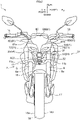
- Fig. 1 is a left side view of a straddled vehicle according to an embodiment.
- Fig. 2 is a front view of the straddled vehicle.
- Fig. 3 is a left side view of a portion of the straddled vehicle.
- Figs. 1 to 3 show a longitudinal direction X, a transverse direction Y, and an up-down direction Z of the straddled vehicle 1.
- the longitudinal direction X, transverse direction Y, and up-down direction Z are defined with reference to a rider mounted on the straddled vehicle 1.
- the longitudinal direction X, transverse direction Y, and up-down direction Z are perpendicular to one another.
- forward and “rearward” include not only directions parallel to the longitudinal direction X but also directions close to the longitudinal direction X.
- the directions close to the longitudinal direction X are, for example, directions at angles not exceeding 45 degrees to the longitudinal direction X.
- “rightward” and “leftward” include not only directions parallel to the transverse direction Y but also directions close to the transverse direction Y.
- upward and downward include not only directions parallel to the up-down direction Z but also directions close to the up-down direction Z.
- the drawings show, by way of reference, forward, rearward, upward, downward, rightward, and leftward as appropriate.
- member A is located rightward / leftward of member B" without reference to a looking direction provides not only a position of member A relative to member B in the transverse direction Y, but also a position of member A relative to member B in the longitudinal direction X, and a position of member A relative to member B in the up-down direction Z. In this positional relationship, member A overlaps at least part of member B in a side view of the vehicle.
- member A is located rightward / leftward of member B in a plan view of the vehicle
- the front end of member A is located more forward than the rear end of member B, and the rear end of member A is located more rearward than the front end of member B.
- this expression does not provide a position of member A relative to member B in the up-down direction Z.
- member A is located rightward / leftward of member B in a front view of the vehicle
- the upper end of member A is located higher than the lower end of member B, and the lower end of member A is located lower than the upper end of member B.
- this expression does not provide a position of member A relative to member B in the longitudinal direction X.
- member A is located forward / rearward of member B in a plan view of the vehicle” or "member A is located above / below member B in a front view of the vehicle” indicates that the right end of member A is located more rightward than the left end of member B, and that the left end of member A is located more leftward than the right end of member B.
- the straddled vehicle 1 is a street type vehicle, for example.
- the rider is mounted on the straddled vehicle 1 and controls the straddled vehicle 1.
- the straddled vehicle 1 can make turns as the straddled vehicle 1 leans right or left.
- the straddled vehicle 1 has a body frame 3.
- the body frame 3 includes a head tube 4.
- the head tube 4 is located at the front of the straddled vehicle 1.
- the head tube 4 extends forward and downward in a side view of the vehicle.
- the body frame 3 includes a left main frame 5L.
- the left main frame 5L is connected to the head tube 4.
- the left main frame 5L extends rearward from the head tube 4. More particularly, the left main frame 5L extends rearward and downward from the head tube 4 in the side view of the vehicle.
- the body frame 3 further includes a right main frame (not shown).
- the right main frame is located rightward of the left main frame 5L.
- the right main frame overlaps the left main frame 5L in the side view of the vehicle.
- the right main frame is connected to the head tube 4.
- the right main frame extends rearward from the head tube 4.
- the straddled vehicle 1 has a steering device 7, a front axle 17, and a front wheel 18.
- the steering device 7 is supported by the head tube 4.
- the steering device 7 is rotatable relative to the head tube 4.
- the steering device 7 includes a handlebar 16 disposed on an upper part of the steering device 7.
- the handlebar 16 is operated by the driver (rider) of the straddled vehicle 1.
- the front axle 17 is supported by a lower part of the steering device 7.
- the front wheel 18 is supported by the front axle 17.
- the steering device 7 has a right front suspension 8 and a left front suspension 9.
- the right front suspension 8 is located rightward of the left front suspension 9.
- the right front suspension 8 is located more rightward than the head tube 4.
- the left front suspension 9 is located more leftward than the head tube 4.
- the right front suspension 8 is located rightward of the front wheel 18.
- the left front suspension 9 is located leftward of the front wheel 18. Both the right front suspension 8 and left front suspension 9 support the front axle 17.
- the left front suspension 9 overlaps the head tube 4 in the side view of the vehicle.
- the left front suspension 9 extends downward and forward in the side view of the vehicle.
- the right front suspension 8 has the same construction and shape as the left front suspension 9 except for being symmetric.
- the right front suspension 8 overlaps the left front suspension 9 in the side view of the vehicle.
- the right front suspension 8 overlaps the head tube 4 in the side view of the vehicle.
- the right front suspension 8 extends downward and forward in the side view of the vehicle.
- the steering device 7 has an under bracket 11.
- the under bracket 11 connects the right front suspension 8 and left front suspension 9.
- the under bracket 11 is located below the head tube 4.
- the under bracket 11 is located above the front wheel 18.
- the under bracket 11 has an upper surface 12.
- the upper surface 12 is clearly seen in Fig. 14 also.
- the upper surface 12 extends in the transverse direction Y between the right front suspension 8 and left front suspension 9.
- the upper surface 12 slopes rearward and downward.
- the upper surface 12 is substantially orthogonal to the extending direction of the left front suspension 9.
- the under bracket 11 is an example of the bracket according to the present teaching.
- the steering device 7 has an upper bracket 13.
- the upper bracket 13 is located higher than the under bracket 11.
- the upper bracket 13 is located above the head tube 4.
- the upper bracket 13 connects the right front suspension 8 and left front suspension 9.
- the steering device 7 has a steering shaft 15.
- the steering shaft 15 is shown in Fig. 14 .
- the steering shaft 15 is mounted in the head tube 4.
- the steering shaft 15 connects the under bracket 11 and upper bracket 13.
- FIG. 1 A portion of the right front suspension 8 located higher than the under bracket 11 will be called “upper right portion”. A portion of the left front suspension 9 located higher than the under bracket 11 will be called “upper left portion”. At least part of the upper right portion is visible in the side view of the vehicle. That is, at least part of the upper right portion is exposed in the side view of the vehicle. Similarly, at least part of the upper left portion is visible in the side view of the vehicle. At least part of the under bracket 11 is visible in the side view of the vehicle.
- FIG. 2 At least part of the upper right portion is visible in the front view of the vehicle. At least part of the upper left portion is visible in the front view of the vehicle. At least part of the under bracket 11 is visible in the front view of the vehicle.
- the straddled vehicle 1 has a front fender 19.
- the front fender 19 is located above the front wheel 18.
- the front fender 19 covers an upper part of the front wheel 18.
- the front fender 19 is located below the head tube 4.
- the front fender 19 is located below the under bracket 11.
- the front fender 19 is supported by the steering device 7.
- the front fender 19 is supported by the right front suspension 8 and left front suspension 9.
- the front fender 19 has a front end 19a and a rear end 19b.
- the front fender 19 extends in the longitudinal direction X between the front end 19a and rear end 19b.
- the front end 19a is located in front of the left front suspension 9 in the side view of the vehicle.
- the rear end 19b is located behind the left front suspension 9 in the side view of the vehicle.
- the front fender 19 includes a portion located in front of the left front suspension 9 and a portion located behind the left front suspension 9 in the side view of the vehicle.
- the straddled vehicle 1 has an engine 21.
- the engine 21 generates power for running the straddled vehicle 1.
- the straddled vehicle 1 has a tank cover 22 and a fuel tank (not shown).
- the tank cover 22 is located above the engine 21 in the side view of the vehicle. At least part of the tank cover 22 is located above the left main frame 5L in the side view of the vehicle.
- the tank cover 22 is located in a position overlapping the fuel tank in the side view of the vehicle.
- the tank cover 22 covers sides of the fuel tank.
- the fuel tank is located above the engine 21 in the side view of the vehicle.
- the fuel tank is located above the left main frame 5L in the side view of the vehicle.
- the fuel tank is supported by the left main frame 5L and right main frame.
- Fig. 3 omits illustration of the tank cover 22 and the fuel tank.
- the straddled vehicle 1 has a seat 23.
- the seat 23 is located behind the fuel tank. At least part of the seat 23 is located in the same height position as the fuel tank.
- the driver (rider) of the straddled vehicle 1 sits straddling the seat 23, puts on a knee grip, and grasps the handlebar 16.
- the knee grip is a holding of part of the straddled vehicle 1 between the driver's (rider's) legs.
- the part of the straddled vehicle 1 is at least part of the right main frame, left main frame 5L, tank cover 22, and fuel tank, for example.
- the straddled vehicle 1 has one headlight 31.
- the headlight 31 emits light ahead of the straddled vehicle 1.
- the straddled vehicle 1 has a leakproof cover 51 and a top cover 61.
- the leakproof cover 51 reduces leakage of the light of the headlight 31.
- the top cover 61 also reduces leakage of the light of the headlight 31.
- the headlight 31, leakproof cover 51, top cover 61, and constructions relating to these will be described hereinafter.
- Figs. 1 and 3 At least part of the headlight 31 is visible in the side view of the vehicle. More particularly, the same headlight 31 is visible in the right side view and the left side view. The size of the headlight 31 is relatively small.
- the headlight 31 overlaps the head tube 4 in the front view of the vehicle.
- the headlight 31 is located more leftward than the right front suspension 8.
- the headlight 31 is located more rightward than the left front suspension 9.
- the headlight 31 is located above the under bracket 11 in the front view of the vehicle.
- the under bracket 11 has a right end 11a and a left end 11b.
- the headlight 31 is located more leftward than the right end 11a and more rightward than the left end 11b.
- the headlight 31 is located above the front fender 19 in the front view of the vehicle.
- the headlight 31 is located above the front wheel 18 in the front view of the vehicle.
- the front wheel 18 has a right end 18a and a left end 18b.
- the headlight 31 is located more leftward than the right end 18a and more rightward than the left end 18b.
- the headlight 31 is located in front of the head tube 4 in the side view of the vehicle.
- the head tube 4 has a rear end 4a and a lower end 4b.
- the lower end 4b is located more forward and lower than the rear end 4a.
- the headlight 31 is located lower than the rear end 4a.
- the headlight 31 is located higher than the lower end 4b.
- the headlight 31 has a portion overlapping the left front suspension 9 and a portion located in front of the left front suspension 9 in the side view of the vehicle.
- the left front suspension 9 has a rear edge 9b in the side view of the vehicle.
- the rear edge 9b extends downward and forward in the side view of the vehicle.
- the headlight 31 is located in front of the rear edge 9b in the side view of the vehicle.
- the left front suspension 9 has an upper end 9c.
- the headlight 31 is located lower than the upper end 9c.
- the headlight 31 is located above the under bracket 11 in the side view of the vehicle.
- the headlight 31 includes a portion located more forward than the under bracket 11.
- the under bracket 11 has a front end 11c and a rear end 11d.
- the under bracket 11 extends in the longitudinal direction X between the front end 11c and rear end 11d.
- the headlight 31 has a front end 31a and a rear end 31b.
- the headlight 31 extends in the longitudinal direction X between the front end 31a and rear end 31b.
- the front end 31a of the headlight 31 is located more forward than the under bracket 11.
- the rear end 31b of the headlight 31 is located more rearward than the front end 11c of the under bracket 11 and more forward than the rear end 11d of the under bracket 11.
- the headlight 31 is located lower and more forward than the upper bracket 13.
- the headlight 31 is located more rearward than the front end 19a of the front fender 19.
- Fig. 4 is a perspective view of the headlight 31.
- Fig. 5 is a sectional view of the headlight 31 cut through a plane perpendicular to the transverse direction Y.
- the headlight 31 is the projector type as described in detail hereinafter.
- the headlight 31 can therefore easily be reduced in size while securing the quantity of light of the headlight 31.
- the headlight 31 has a light source 32, a housing 34, and a convex lens 38.
- the light source 32 emits light.
- the housing 34 stores the light source 32.
- the convex lens 38 is attached to the housing 34.
- Fig. 5 omits hatches showing a section of the convex lens 38.
- the light source 32 is a semiconductor light source, for example.
- the semiconductor light source is at least one of a light emitting diode (LED), an organic electroluminescence element, and a laser diode, for example.
- the light emitted from the light source 32 desirably has high directivity.
- the light emitted from the light source 32 desirably has high straight traveling performance.
- the number of light sources 32 stored in the housing 34 may be one or more.
- the light source 32 is limited to the light source of the headlight 31.
- the housing 34 does not store any light sources other than the light source 32 of the headlight 31.
- the housing 34 does not store light sources for position lights.
- the light source 32 of the headlight 31 will be described.
- the light source 32 of the headlight 31 mainly emits light for securing visibility for the rider. For example, even when it is dark around the straddled vehicle 1 (e.g. at night), the rider can easily see the traveling surface ahead of the straddled vehicle 1 by the light from the light source 32 of the headlight 31.
- the light source 32 of the headlight 31 may be a light source for high beams, or may be a light source for low beams, for example.
- the light sources for the position lights mainly emit light for securing conspicuity of the straddled vehicle 1.
- a third party other than the riders (including the driver) on the straddled vehicle 1 can easily recognize the size (e.g. the vehicle width) of the straddled vehicle 1 by the light of the light sources for the position lights.
- the headlight 31 has a base plate 33.
- the light source 32 is installed on a front face of the base plate 33.
- the base plate 33 is also stored in the housing 34.
- the housing 34 has a box portion 35 and an interior space 36.
- the box portion 35 has a substantially rectangular shape in the plan view and side view of the vehicle.
- the box portion 35 has a light blocking property. That is, the box portion 35 does not transmit light.
- the interior space 36 is formed inside the box portion 35.
- the box portion 35 has an opening formed in a front face thereof.
- the light source 32 and base plate 33 are arranged in the interior space 36.
- the box portion 35 covers an upper part, a lower part, a right part, a left part, and a rear part of the light source 32.
- the housing 34 has a heat radiator 37.
- the heat radiator 37 is connected to the box portion 35.
- the heat radiator 37 includes upper radiator fins 37a and left heat radiator fins 37b.
- the upper radiator fins 37a are connected to an upper surface of the box portion 35.
- the upper radiator fins 37a project upward from the box portion 35.
- the left radiator fins 37b are connected to a left side of the box portion 35.
- the left radiator fins 37b project leftward from the box portion 35.
- the heat radiator 37 further includes right radiator fins 37c.
- the right radiator fins 37c are shown in Fig. 7 .
- the convex lens 38 transmits light.
- the convex lens 38 refracts light.
- the convex lens 38 has a substantially hemispherical shape in the side view and plan view of the vehicle.
- the convex lens 38 has a front face 39 and a rear face 40.
- the front face 39 is curved to bulge forward.
- the front face 39 is curved to have a substantially hemispherical shape in the side view and plan view of the vehicle.
- the front face 39 includes the front end 31a of the headlight 31. That is, a front end of the front face 39 corresponds to the front end 31a of the headlight 31.
- the rear face 40 is located behind the front face 39.
- the rear face 40 is substantially flat.
- the rear face 40 is substantially perpendicular to the longitudinal direction X.
- Fig. 6 is a front view of a portion of the straddled vehicle 1.
- the convex lens 38 has a substantially rectangular shape in the front view of the vehicle.
- the convex lens 38 has a substantially square shape in the front view of the vehicle.
- the front end 31a is located substantially at the center of the convex lens 38 in the front view of the vehicle.
- the convex lens 38 has an edge portion 41.
- the edge portion 41 is located around the front end 31a in the front view of the vehicle.
- the edge portion 41 has a substantially rectangular shape in the front view of the vehicle.
- the headlight 31 has a flange 42.
- the flange 42 is located around the convex lens 38 in the front view of the vehicle.
- the flange 42 is connected to the convex lens 38.
- the flange 42 is connected to the edge portion 41.
- the flange 42 extends upward, downward, rightward, and leftward from the edge portion 41 in the front view of the vehicle.
- the flange 42 has a substantially rectangular shape in the front view of the vehicle.
- the edge portion 41 is located more rearward than the front end 31a.
- the flange 42 is located more rearward than the front end 31a.
- the flange 42 extends upward and downward from the edge portion 41 in the side view of the vehicle.
- the convex lens 38 is attached to a front face of the housing 34. More particularly, the flange 42 is in contact with the front face of the box portion 35. The flange 42 is joined to the box portion 35. Thus, the convex lens 38 is connected to the box portion 35 through the flange 42.
- the convex lens 38 is located in front of the light source 32.
- the convex lens 38 closes the interior space 36.
- the interior space 36 is demarcated only by the box portion 35 and convex lens 38.
- the convex lens 38 (specifically the front face 39) is exposed to the exterior of the straddled vehicle 1.
- the headlight 31 does not have a member (e.g. a clear cover) that covers an area in front of the convex lens 38.
- the straddled vehicle 1 does not also have a member (e.g. a clear cover) that covers the area in front of the convex lens 38.
- Fig. 5 schematically shows, in broken lines, light traveling forward of the headlight 31 from the light source 32.
- the light is emitted from the light source 32.
- the light passes through the convex lens 38.
- the light travels from the rear face 40 of the convex lens 38 to the front face 39 of the convex lens 38.
- the light is refracted.
- the light is emitted from the front face 39.
- the light travels forward from the front face 39.
- the light traveling forward from the front face 39 is parallel light, for example.
- Fig. 5 shows, in alternate long and short dash lines, light traveling from the front face 39 in directions other than forward of the headlight 31.
- a fraction of the light may travel from the front face 39 in at least one of upward, downward, rightward and leftward directions of the headlight 31.
- part of the light emitted from the front face 39 may travel in directions approximate to tangents to the front face 39. For example, therefore, a fraction of light may travel from the front face 39 rearward of the headlight 31.
- the convex lens 38 is located more forward than the left front suspension 9.
- the convex lens 38 is located more forward than the under bracket 11.
- Part of the convex lens 38 is visible in the side view of the vehicle. Specifically, an upper part of the convex lens 38 is visible in the side view of the vehicle.
- the front end 31a of the headlight 31 is visible in the side view of the vehicle.
- Part of the housing 34 is visible in the side view of the vehicle.
- Part of the flange 42 is visible in the side view of the vehicle.
- the convex lens 38 is visible in the front view of the vehicle.
- the flange 42 is visible in the front view of the vehicle.
- the upper radiator fins 37a are visible in the front view of the vehicle.
- the leakproof cover 51 has at least a light reducing property. In this embodiment, the leakproof cover 51 has a light blocking property. That is, the leakproof cover 51 does not transmit light.
- the leakproof cover 51 is formed of a non-transparent material.
- the leakproof cover 51 is formed of a colored synthetic resin, for example.
- the leakproof cover 51 overlaps the head tube 4 in the front view of the vehicle.
- the leakproof cover 51 overlaps the right front suspension 8 and left front suspension 9 in the front view of the vehicle.
- the leakproof cover 51 is located leftward of a right edge 8a of the right front suspension 8 in the front view of the vehicle.
- the leakproof cover 51 is located rightward of a left edge 9a of the left front suspension 9 in the front view of the vehicle.
- the leakproof cover 51 is located above the under bracket 11 in the front view of the vehicle.
- the leakproof cover 51 is located more leftward than the right end 11a of the under bracket 11 and more rightward than the left end 11b of the under bracket 11.
- the leakproof cover 51 is located in front of the head tube 4 in the side view of the vehicle.
- the leakproof cover 51 is located lower than the rear end 4a of the head tube 4, and higher than the lower end 4b of the head tube 4.
- the leakproof cover 51 includes a portion located in front of the left front suspension 9 and a portion overlapping the left front suspension 9 in the side view of the vehicle.
- the leakproof cover 51 does not include a portion located behind the left front suspension 9 in the side view of the vehicle.
- the leakproof cover 51 is located in front of the rear edge 9b of the left front suspension 9 in the side view of the vehicle.
- the leakproof cover 51 is located lower than the upper end 9c of the left front suspension 9.
- the leakproof cover 51 is located above the under bracket 11 in the side view of the vehicle.
- the leakproof cover 51 includes a portion located more forward than the under bracket 11.
- the leakproof cover 51 has front ends 51a and a rear end 51b.
- the leakproof cover 51 extends in the longitudinal direction X between the front ends 51a and rear end 51b.
- the front ends 51a of the leakproof cover 51 are located more forward than the under bracket 11.
- the rear end 51b of the leakproof cover 51 is located more rearward than the front end 11c of the under bracket 11, and more forward than the rear end 11d of the under bracket 11.
- the leakproof cover 51 is located more forward and lower than the upper bracket 13.
- the leakproof cover 51 does not overlap the head tube 4, under bracket 11, or upper bracket 13 in the side view of the vehicle.
- the leakproof cover 51 is located more rearward than the front end 19a of the front fender 19.
- the leakproof cover 51 overlaps part of the headlight 31 in the side view of the vehicle.
- the leakproof cover 51 overlaps part of the convex lens 38 in the side view of the vehicle.
- the leakproof cover 51 overlaps part of the housing 34 in the side view of the vehicle.
- the front ends 51a of the leakproof cover 51 are located more forward than the front end 31a of the headlight 31.
- the front ends 51a and rear end 51b of the leakproof cover 51 are located lower than the front end 31a of the headlight 31, respectively.
- the rear end 51b of the leakproof cover 51 is located more rearward than the convex lens 38.
- the rear end 51b of the leakproof cover 51 is located more forward than the rear end 31b of the headlight 31.
- the leakproof cover 51 is located below the headlight 31 in the front view of the vehicle. Specifically, the leakproof cover 51 includes a portion located below the headlight 31, a portion located rightward of the headlight 31, and a portion located leftward of the headlight 31 in the front view of the vehicle. The leakproof cover 51 does not include a portion located above the headlight 31 in the front view of the vehicle.
- the leakproof cover 51 is substantially U-shaped in the front view of the vehicle.
- the leakproof cover 51 has a shape covering a lower part, a right part, and a left part of the headlight 31 in the front view of the vehicle.
- the leakproof cover 51 is shaped not to cover an upper part of the headlight 31. More particularly, the leakproof cover 51 is shaped not to cover an upper part, a front part, or a rear part of the headlight 31.
- the leakproof cover 51 is located in a position spaced from the headlight 31. That is, the leakproof cover 51 is located in a position out of contact with the headlight 31.
- the leakproof cover 51 does not overlap the convex lens 38 in the front view of the vehicle.
- the leakproof cover 51 does not surround the convex lens 38 to close the circumference of the latter.
- the leakproof cover 51 does not contact the edge portion 41 of the convex lens 38.
- the leakproof cover 51 does not overlap the flange 42 in the front view of the vehicle.
- the leakproof cover 51 has a first shielding portion 52.
- the first shielding portion 52 is located below the convex lens 38.
- the first shielding portion 52 is located higher than the under bracket 11.
- the first shielding portion 52 is, in the front view of the vehicle, located leftward of the right front suspension 8 and rightward of the left front suspension 9.
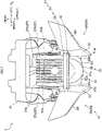
- Fig. 7 is a plan view of the headlight 31 and leakproof cover 51.
- Fig. 8 is a bottom view of the headlight 31, leakproof cover 51, and top cover 61.
- the first shielding portion 52 overlaps part of the convex lens 38 in the plan view of the vehicle. Specifically, the first shielding portion 52 overlaps most portions of the convex lens 38 in the plan view of the vehicle.
- the front end 31a of the headlight 31 is located more forward than the first shielding portion 52.
- the first shielding portion 52 does not overlap parts of the convex lens 38 located near the front end 31a of the headlight 31 in the plan view of the vehicle.
- the first shielding portion 52 has a substantially horizontal plate shape.
- the first shielding portion 52 has a front edge 52a and a rear edge 52b in the plan view of the vehicle.
- the front edge 52a is located in front of most portions of the convex lens 38 in the plan view of the vehicle.
- the front edge 52a is curved to bulge forward in the plan view of the vehicle.
- the front edge 52a is curved more gently than the convex lens 38 in the plan view of the vehicle.
- the rear edge 52b is located behind the convex lens 38 in the plan view of the vehicle.
- the first shielding portion 52 extends substantially in the longitudinal direction X between the front edge 52a and rear edge 52b in the plan view of the vehicle.
- the first shielding portion 52 has a right edge 52c and a left edge 52d in the plan view of the vehicle.
- the right edge 52c is located rightward of the convex lens 38 in the plan view of the vehicle.
- the left edge 52d is located leftward of the convex lens 38 in the plan view of the vehicle.
- the first shielding portion 52 extends substantially in the transverse direction Y between the right edge 52c and left edge 52d in the plan view of the vehicle.
- the first shielding portion 52 overlaps part of the housing 34 in the plan view of the vehicle.
- the first shielding portion 52 is located in front of the rear end 31b of the headlight 31 in the plan view of the vehicle.
- the first shielding portion 52 has an upper surface 53.
- the upper surface 53 is substantially level in the front view of the vehicle. More strictly, the upper surface 53 is slightly curved to bulge downward in the front view of the vehicle.
- the upper surface 53 is located higher than the under bracket 11.
- the leakproof cover 51 has a second shielding portion 54.
- the second shielding portion 54 is located rightward of the convex lens 38 and leftward of the convex lens 38.
- the second shielding portion 54 is located higher than the under bracket 11.
- the second shielding portion 54 has a right shielding portion 55 and a left shielding portion 56.
- the right shielding portion 55 is located rightward of the convex lens 38.
- the left shielding portion 56 is located leftward of the convex lens 38.
- Part of the right shielding portion 55 e.g. an upper end 55b to be described hereinafter overlaps the right front suspension 8 in the front view of the vehicle.
- Part of the left shielding portion 56 (e.g. an upper end 56b to be described hereinafter) overlaps the left front suspension 9 in the front view of the vehicle.
- the right shielding portion 55 has the same construction and shape as the left shielding portion 56 except for being symmetric.
- the right shielding portion 55 is connected to the first shielding portion 52.
- the right shielding portion 55 is connected to the right edge 52c.
- the left shielding portion 56 is connected to the first shielding portion 52.
- the left shielding portion 56 is connected to the left edge 52d.
- the right shielding portion 55 extends upward and rightward from the first shielding portion 52 in the front view of the vehicle. In the front view of the vehicle, a spacing in the transverse direction Y between the right shielding portion 55 and convex lens 38 enlarges upward.
- the left shielding portion 56 extends upward and leftward from the first shielding portion 52 in the front view of the vehicle. In the front view of the vehicle, a spacing in the transverse direction Y between the left shielding portion 56 and convex lens 38 enlarges upward.
- the right shielding portion 55 has a lower end 55a and an upper end 55b.
- the lower end 55a is located lower than the convex lens 38.
- the upper end 55b is located more rightward and higher than the lower end 55a.
- the upper end 55b is located higher than the convex lens 38.
- the left shielding portion 56 has a lower end 56a and an upper end 56b.
- the lower end 56a is located lower than the convex lens 38.
- the upper end 56b is located more leftward and higher than the lower end 56a.
- the upper end 56b is located higher than the convex lens 38.
- the right shielding portion 55 includes a lower part 57 and an upper part 58.
- the lower part 57 is connected to the first shielding portion 52.
- the upper part 58 is connected to the lower part 57.
- the upper part 58 is located higher than the lower part 57.
- the lower part 57 and upper part 58 extend upward and rightward in the front view of the vehicle, respectively.
- the upper part 58 has an inclination in the front view of the vehicle which is closer to the horizontal than that of the lower part 57.
- the left shielding portion 56 includes a lower part 59 and an upper part 60.
- the lower part 59 is connected to the first shielding portion 52.
- the upper part 60 is connected to the lower part 59.
- the upper part 60 is located higher than the lower part 59.
- the lower part 59 and upper part 60 extend upward and leftward in the front view of the vehicle, respectively.
- the upper part 60 has an inclination in the front view of the vehicle which is closer to the horizontal than that of the
- the left shielding portion 56 overlaps the convex lens 38 in the side view of the vehicle.
- the lower part 59 and upper part 60 overlap the convex lens 38 in the side view of the vehicle, respectively.
- the right shielding portion 55 overlaps the convex lens 38 in the side view of the vehicle.
- the lower part 57 and upper part 58 overlap the convex lens 38 in the side view of the vehicle, respectively.
- the upper end 56b is located more rearward than the convex lens 38.
- the upper end 55b is located more rearward than the convex lens 38.
- the lower parts 57 and 59 project more forward than the front edge 52a in the plan view of the vehicle, respectively.
- the lower parts 57 and 59 include the front ends 51a of the leakproof cover 51, respectively.
- the front end 51a included in the lower part 57 is located more rightward than the convex lens 38.
- the front end 51a included in the lower part 59 is located more leftward than the convex lens 38.
- the front end 51a included in the lower part 57 may be in the same position as the lower end 55a, or may be in a position adjacent the lower end 55a. The same may be said of the front end 51a included in the lower part 59 and the lower end 56a of the left shielding portion 56.
- the upper part 58 extends rightward and rearward from the lower part 57 in the plan view of the vehicle.
- the upper part 60 extends leftward and rearward from the lower part 59 in the plan view of the vehicle.
- the top cover 61 has a light blocking property. That is, the top cover 61 does not transmit light.
- the top cover 61 is formed of a non-transparent material.
- the top cover 61 is formed of a colored synthetic resin, for example.
- the top cover 61 has a first cover 63, a second cover 64, and a third cover 65.
- the first cover 63, second cover 64, and third cover 65 are connected to one another.
- the first cover 63, second cover 64, and third cover 65 are separable from one another.
- the first cover 63 extends in the transverse direction Y in the front view of the vehicle.
- the second cover 64 is located above the first cover 63.
- the second cover 64 extends upward and rearward from the first cover 63.
- the third cover 65 is located behind the first cover 63 and behind the second cover 64.
- the third cover 65 covers a rear part of the first cover 63 and a rear part of the second cover 64 from behind.
- the top cover 61 overlaps the head tube 4 in the front view of the vehicle.
- the top cover 61 overlaps the right front suspension 8 and left front suspension 9 in the front view of the vehicle.
- the top cover 61 has a right end 61a and a left end 61b.
- the top cover 61 extends substantially in the transverse direction Y between the right end 61a and left end 61b in the front view of the vehicle.
- the right end 61a is located more rightward than the right front suspension 8.
- the left end 61b is located more leftward than the left front suspension 9.
- the top cover 61 is located above the under bracket 11 in the front view of the vehicle.
- the under bracket 11 is located more leftward than the right end 61a of the top cover 61 and more rightward than the left end 61b of the top cover 61.
- the top cover 61 is located in front of the head tube 4 in the side view of the vehicle.
- the top cover 61 has an upper end 61c and a lower end 61d.
- the top cover 61 extends in the up-down direction Z between the upper end 61c and lower end 61d.
- the upper end 61c is located higher than the head tube 4.
- the lower end 61d is located lower than the rear end 4a of the head tube 4, and higher than the lower end 4b thereof.
- the top cover 61 is located in front of the left front suspension 9 in the side view of the vehicle.
- the upper end 61c of the top cover 61 is located higher than the left front suspension 9.
- the lower end 61d of the top cover 61 is located lower than the upper end 9c of the left front suspension 9.
- the top cover 61 is located above under bracket 11 in the side view of the vehicle.
- the top cover 61 includes a portion located more forward than the under bracket 11.
- the top cover 61 has a front end 61e and a rear end 61f.
- the top cover 61 extends in the longitudinal direction X between the front end 61e and rear end 61f.
- the under bracket 11 is located more rearward than the front end 61e of the top cover 61.
- the under bracket 11 is located more forward than the rear end 61f of the top cover 61.
- the top cover 61 is located in front of the upper bracket 13 in the side view of the vehicle.
- the upper bracket 13 is located lower than the upper end 61c of the top cover 61 and higher than the lower end 61d of the top cover 61.
- top cover 61 does not overlap the head tube 4, right front suspension 8, left front suspension 9, under bracket 11, or upper bracket 13 in the side view of the vehicle.
- the top cover 61 is located above the headlight 31 in the side view of the vehicle.
- the headlight 31 is located more rearward than the front end 61e of the top cover 61.
- the headlight 31 is located more forward than the rear end 61f of the top cover 61.
- the top cover 61 is located above the leakproof cover 51 in the side view of the vehicle.
- the leakproof cover 51 is located more rearward than the front end 61e of the top cover 61.
- the leakproof cover 51 is located more forward than the rear end 61f of the top cover 61.
- the top cover 61 is located more rearward than the front end 19a of the front fender 19.
- the straddled vehicle 1 has a clearance space 62.
- the clearance space 62 is formed below the top cover 61 and above the headlight 31.
- the clearance space 62 is limited to a range which overlaps at least either the top cover 61 or the headlight 31 in the plan view of the vehicle.
- the clearance space 62 is a space which separates the headlight 31 and top cover 61.
- the clearance space 62 is distinguishable in the side view of the vehicle. That is, at least part of an upper edge of the headlight 31 and at least part of a lower edge of the top cover 61 are visible in the side view of the vehicle.
- the clearance space 62 is open forward.
- the front of the clearance space 62 is not covered. That is, the straddled vehicle 1 has no component covering the front of the clearance space 62.
- the clearance space 62 is open rightward and leftward. A right part and a left part of the clearance space 62 are not covered. That is, the straddled vehicle 1 has no component covering the right part of the clearance space 62. The straddled vehicle 1 has no component covering the left part of the clearance space 62.
- the far side of the straddled vehicle 1 is visible through the clearance space 62.
- the straddled vehicle 1 is seen from a position leftward of the straddled vehicle 1, objects other than the straddled vehicle 1 located rightward of the straddled vehicle 1 are visible through the clearance space 62.
- the top cover 61 is located above the headlight 31.
- the headlight 31 is located more leftward than the right end 61a of the top cover 61 and more rightward than the left end 61b of the top cover 61.
- the top cover 61 is shaped to cover the upper part of the headlight 31.
- the top cover 61 is shaped not to cover the lower part, right part, or left part of the headlight 31. More particularly, the top cover 61 has a shape not covering the lower part, right part, left part, front part, or rear part of the headlight 31.
- the top cover 61 is located in a position spaced from the headlight 31. That is, the top cover 61 is located in a position out of contact with the headlight 31.
- the top cover 61 is located above the leakproof cover 51.
- the leakproof cover 51 is located more leftward than the right end 61a of the top cover 61 and more rightward than the left end 61b of the top cover 61.
- the top cover 61 is located in a position spaced from leakproof cover 51. That is, the top cover 61 is located in a position out of contact with the leakproof cover 51.
- the top cover 61 does not overlap the convex lens 38 in the front view of the vehicle.
- the top cover 61 does not surround the circumference of the convex lens 38 in the front view of the vehicle.
- the top cover 61 does not contact the edge portion 41 of convex lens 38.
- the top cover 61 does not overlap the flange 42 in the front view of the vehicle.
- Fig. 9 is a plan view of the top cover 61 and headlight 31.
- the top cover 61 overlaps the convex lens 38 in the plan view of the vehicle.
- the top cover 61 overlaps the headlight 31 in the plan view of the vehicle.
- the top cover 61 overlaps part of the leakproof cover 51 in the plan view of the vehicle.
- the top cover 61 overlaps the entire first shielding portion 52 in the plan view of the vehicle.
- the top cover 61 overlaps most of the second shielding portion 54 in the plan view of the vehicle.
- the top cover 61 does not overlap the front ends 51a of the leakproof cover 51 in the plan view of the vehicle.
- the top cover 61 does not overlap the portion located adjacent the front ends 51a of the leakproof cover 51 in the plan view of the vehicle.
- the straddled vehicle 1 has position lights 71.
- the position lights 71 emit light ahead of the straddled vehicle 1.
- the position lights 71 have a less quantity of light than the headlight 31.
- the position lights 71 are supported by the top cover 61. Specifically, the position lights 71 are supported by the first cover 63.
- the position lights 71 include a right position light 72 and a left position light 75.
- the left position light 75 is located leftward of the right position light 72.
- the left position light 75 is located in a position spaced from the right position light 72.
- the right position light 72 has the same construction and shape as the left position light 75 except for being symmetric.
- the left position light 75 overlaps the right position light 72 in the side view of the vehicle.
- the right position light 72 has an elongated shape extending substantially horizontally (specifically, substantially in the transverse direction Y) in the front view of the vehicle.
- the left position light 75 has an elongated shape extending substantially horizontally (specifically, substantially in the transverse direction Y) in the front view of the vehicle.
- the right position light 72 is located more rightward than the head tube 4.
- the left position light 75 is located more leftward than the head tube 4.
- the position lights 71 are located more leftward than the right edge 8a of the right front suspension 8 in the front view of the vehicle.
- the position lights 71 are located more leftward than the left edge 9a of the left front suspension 9 in the front view of the vehicle.
- the position lights 71 are located above the under bracket 11 in the front view of the vehicle.
- the position lights 71 are located more leftward than the right end 11a of the under bracket 11 and more rightward than the left end 11b of the under bracket 11.
- the position lights 71 have an elongated shape extending substantially horizontally (specifically, substantially in the longitudinal direction X) in the side view of the vehicle.
- the position lights 71 are located in front of the head tube 4 in the side view of the vehicle.
- the position lights 71 are located lower than the rear end 4a of the head tube 4 and higher than the lower end 4b thereof.
- the position lights 71 are located in front of the left front suspension 9 in the side view of the vehicle.
- the position lights 71 are located lower than the upper end 9c of the left front suspension 9.
- the position lights 71 are located more forward and higher than the under bracket 11.
- the position lights 71 are located above the headlight 31 in the side view of the vehicle.
- the position lights 71 are located more rearward than the front end 31a of the headlight 31 and more forward than the rear end 31b of the headlight 31.
- the position lights 71 are located in positions spaced from the headlight 31. That is, the position lights 71 are located in positions out of contact with the headlight 31.
- the position lights 71 are located above the convex lens 38 in the side view of the vehicle.
- the position lights 71 are located above the leakproof cover 51 in the side view of the vehicle.
- the position lights 71 are located more rearward than the front ends 51a of the leakproof cover 51 and more forward than the rear end 51b of the leakproof cover 51.
- the position lights 71 are located lower than the upper end 61c of the top cover 61 and higher than the lower and 61d of the top cover 61.
- the position lights 71 are located more rearward than the front end 61e of the top cover 61 and more forward than the rear end 61f of the top cover 61.
- the right position light 72 is located higher than the convex lens 38.
- the right position light 72 is located more rightward than the convex lens 38.
- the left position light 75 is located higher than the convex lens 38.
- the left position light 75 is located more leftward than the convex lens 38.
- the top cover 61 surrounds the circumference of the right position light 72 in the front view of the vehicle.
- the top cover 61 contacts edges of the right position light 72.
- the top cover 61 surrounds the circumference of the left position light 75 in the front view of the vehicle.
- the top cover 61 contacts edges of the left position light 75.
- the top cover 61 has a right opening (not shown) and a left opening (not shown).
- the right position light 72 has a clear cover 73.
- the left position light 75 has a clear cover 76.
- the clear covers 73 and 76 have light transmissive property, respectively.
- the clear cover 73 is located in the right opening.
- the clear cover 76 is located in the left opening.
- the top cover 61 contacts edges of the clear cover 73 and edges of the clear cover 76.
- the straddled vehicle 1 has flashers 81.
- the flashers 81 emit blinking light.
- the flashers 81 emit blinking light mainly in order to notify third parties of course changes of the straddled vehicle 1, for example.
- the flashers 81 are supported by the top cover 61. Specifically, the flashers 81 are supported by the third cover 65.
- the flashers 81 include a right flasher 82 and a left flasher 83.
- the left flasher 83 is located leftward of the right flasher 82.
- the left flasher 83 is located in a position spaced from the right flasher 82.
- the right flasher 82 has the same construction and shape as the left flasher 83 except for being symmetric.
- the right flasher 82 is located more rightward than the right front suspension 8.
- the left flasher 83 is located more leftward than the left front suspension 9.
- the flashers 81 are located above the left front suspension 9 in the side view of the vehicle.
- the flashers 81 are located higher and more rearward than the position lights 71.
- the flashers 81 are located lower than the upper end 61c of the top cover 61.
- the flashers 81 are located more forward than the rear end 61f of the top cover 61.
- the flashers 81 are located higher than the position lights 71.
- the right flasher 82 is located more rightward than the right position light 72.
- the left flasher 83 is located more leftward than the left position light 75.
- the right flasher 82 includes a portion located more rightward than the right end 61a of the top cover 61.
- the left flasher 83 includes a portion located more leftward than the left end 61b of the top cover 61.
- the flashers 81 are located in positions spaced from the position lights 71 and headlight 31. That is, the flashers 81 are located in positions out of contact with the position lights 71 and headlight 31.
- the top cover 61 does not surround the circumferences of the flashers 81 in the front view of the vehicle.
- the top cover 61 does not contact edges of the flashers 81.
- the straddled vehicle 1 has a meter unit 85.
- the meter unit 85 presents the rider with information about the straddled vehicle 1, for example.
- the information about the straddled vehicle 1 is traveling speeds of the straddled vehicle 1, for example.
- the meter unit 85 has a display portion 85a for displaying the information about the straddled vehicle 1 (see Fig. 9 ).
- the meter unit 85 is supported by the top cover 61. Specifically, the meter unit 85 is supported by the third cover 65.
- the meter unit 85 is located more leftward than the right edge 8a of the right front suspension 8 in the front view of the vehicle.
- the meter unit 85 is located more rightward than the left edge 9a of the left front suspension 9 in the front view of the vehicle.
- the meter unit 85 is located higher and more forward than the rear end 4a of the head tube 4.
- the meter unit 85 is located above the left front suspension 9 in the side view of the vehicle.
- the meter unit 85 is located above the upper bracket 13 in the side view of the vehicle.
- the meter unit 85 is located more forward than the handlebar 16.
- the meter unit 85 is located more rearward and higher than the headlight 31.
- the meter unit 85 is located more rearward and higher than the convex lens 38.
- the meter unit 85 is located more rearward and higher than the leakproof cover 51.
- the meter unit 85 is located higher than the lower end 61d of the top cover 61.
- the meter unit 85 includes a portion located higher than the upper end 61c of the top cover 61, and a portion located lower than the upper end 61c of the top cover 61.
- the meter unit 85 is located more rearward than the front end 61e of the top cover 61.
- the meter unit 85 includes a portion located more forward than the rear end 61f of the top cover 61, and a portion located more rearward than the rear end 61f of the top cover 61.
- the meter unit 85 is located more rearward and higher than the position lights 71.
- the meter unit 85 is located above the flashers 81 in the side view of the vehicle.
- Fig. 6 Part of the meter unit 85 is located above the top cover 61 in the front view of the vehicle.
- the meter unit 85 is located more leftward than the right end 61a of the top cover 61 and more rightward than the left end 61b of the top cover 61.
- the straddled vehicle 1 has a harness 86.
- the harness 86 is a bundle of a plurality of electric wires.
- the harness 86 is an example of electric wiring according to the present teaching.
- Part of the harness 86 is located more forward than the rear end 4a of the head tube 4, more rearward than the headlight 31, and higher than the headlight 31.
- An arrangement of the harness 86 will be described in detail hereinafter.
- the harness 86 includes a first portion 86a, a second portion 86b, and a third portion 86c.
- the first to third portions 86a-86c are located more forward than the rear end 4a of the head tube 4, more rearward than the headlight 31, and higher than the headlight 31, respectively.
- the first portion 86a is located more rearward than the left front suspension 9.
- the first portion 86a overlaps the head tube 4 in the side view of the vehicle.
- the first portion 86a extends upward.
- the second portion 86b extends forward from the first portion 86a in the side view of the vehicle.
- the second portion 86b overlaps the left front suspension 9 in the side view of the vehicle. More particularly, the second portion 86b is located leftward of the right front suspension 8, and rightward of the left front suspension 9. Further, the second portion 86b is located higher than the under bracket 11, and lower rather than the upper bracket 13.
- the third portion 86c extends forward from the second portion 86b in the side view of the vehicle.
- the third portion 86c reaches the top cover 61 (specifically, the third cover 65).
- the third portion 86c is located more forward than the left front suspension 9.
- the harness 86 extends from the first portion 86a via the second portion 86b to the third portion 86c.
- the harness 86 extends forward and upward from the first portion 86a to the third portion 86c in the side view of the vehicle.
- Fig. 10 is a left side view of a portion of the straddled vehicle.
- Fig. 10 omits illustration of the third cover 65. Specifically, Fig. 10 shows the third cover 65 in a broken line.
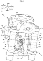
- Fig. 11 is a perspective view of a portion of the straddled vehicle 1 seen from an upper forward position of the straddled vehicle 1.
- Fig. 11 omits illustration of the second cover 64. Specifically, Fig. 11 shows the second cover 64 in a broken line.
- the straddled vehicle 1 has electric wiring 87.
- the electric wiring 87 extends from the handlebar 16 to the top cover 61. A large part of the electric wiring 87 is located more forward than the rear end 4a of the head tube 4, more rearward than the headlight 31, and higher than the headlight 31.
- the straddled vehicle 1 has a plurality of electric wires 88.
- Each electric wire 88 branches from the harness 86.
- Each electric wire 88 is thinner than the harness 86.
- each electric wire 88 has an outside diameter smaller than the harness 86.
- the electric wires 88 are arranged in an interior of the top cover 61.
- the interior of the top cover 61 is demarcated by the first cover 63, second cover 64, and third cover 65.
- the electric wires 88 are arranged more forward than the rear end 4a of the head tube 4, more rearward than the headlight 31, and higher than the headlight 31.
- Fig. 12 is a left side view of a portion of the straddled vehicle 1.
- Fig. 13 is a perspective view of the portion of the straddled vehicle 1 seen from a rear left position of the straddled vehicle 1.
- the headlight 31 is supported by the steering device 7.
- the leakproof cover 51 and top cover 61 are also supported by the steering device 7.
- the straddled vehicle 1 has a support cover 91.
- the support cover 91 is located behind the headlight 31 and leakproof cover 51.
- the straddled vehicle 1 has a mounting shaft 92 and an adjusting screw 93.
- the mounting shaft 92 and adjusting screw 93 are supported by the support cover 91.
- the mounting shaft 92 extends substantially in the transverse direction Y.
- the mounting shaft 92 supports the headlight 31 (specifically the sides of the housing 34).
- the headlight 31 is rotatable about the mounting shaft 92 relative to the support cover 91.
- the adjusting screw 93 is joined to the headlight 31 (specifically the rear of the housing 34). With rotation of the adjusting screw 93, the rear of the housing 34 moves axially of the adjusting screw 93 relative to the support cover 91.
- the headlight 31 rotates about the mounting shaft 92 relative to the support cover 91, thereby moving the direction of the light (i.e. the optical axis) of the headlight 31 up and down. In this way the headlight 31 is rotatably supported by the support cover 91.
- the straddled vehicle 1 has fastening members 94 and 95.
- the fastening member 94 joins the leakproof cover 51 (specifically the second shielding portion 54) and support cover 91.
- the fastening member 95 joins the leakproof cover 51 (specifically the first shielding portion 52) and support cover 91. Consequently, the leakproof cover 51 is fixed to the support cover 91.
- the headlight 31 and leakproof cover 51 are not connected directly.
- the straddled vehicle 1 has no fastening member that directly joins the headlight 31 and leakproof cover 51.
- the straddled vehicle 1 has a pair of stays 96, a bar 97, and fastening members 98 and 99.
- Each stay 96 is a crooked rod-like object.
- the bar 97 connects the pair of stays 96.
- the bar 97 has a first end connected to an upper end of one of the stays 96, and a second end connected to an upper end of the other stay 96. Consequently, the pair of stays 96 and the bar 97 are fixed to each other.
- the fastening members 98 join lateral part of the support cover 91 and the stays 96.
- the fastening members 99 join rear parts of the support cover 91 and the stays 96. Consequently, the support cover 91 is fixed to the stays 96.
- the straddled vehicle 1 has fastening members 100 and 101.
- the fastening member 100 joins the top cover 61 (specifically the third cover 65) and bar 97.
- the fastening member 101 joins the top cover 61 (specifically the third cover 65) and stays 96. Consequently, the top cover 61 is fixed to the stays 96 and bar 97.
- Fig. 14 is a perspective view of a portion of the straddled vehicle 1 seen from a rear left position of the straddled vehicle 1.
- the fastening member 100 is further joined to the upper bracket 13. That is, the fastening member 100 joins the top cover 61, bar 97, and upper bracket 13 all together. Consequently, the top cover 61 and bar 97 are fixed to the upper bracket 13.
- Each stay 96 has a lower end 96a.
- Each lower end 96a is joined to the under bracket 11. Specifically, each lower end 96a is inserted in a recess (not shown) formed in the upper surface 12 of the under bracket 11. Each lower end 96a is held by the under bracket 11. Consequently, each stay 96 is fixed to the under bracket 11.
- the fastening members 94-95 and 98-101 are bolts, nuts, screws, and the like, for example.
- Fig. 8 and other figures omit illustration as appropriate of the adjusting screw 93 or fastening members 94-95 and 98-101.
- the steering device 7 supports the headlight 31, leakproof cover 51, and top cover 61. Since the top cover 61 supports the position lights 71, flashers 81, and meter unit 85, the steering device 7 also supports the position lights 71, flashers 81, and meter unit 85.
- the leakproof cover 51 has the first shielding portion 52.
- the first shielding portion 52 is located below the convex lens 38. That is, the first shielding portion 52 overlaps part of the convex lens 38 in plan view.
- the first shielding portion 52 can therefore block light emitted downward from the headlight 31. This can reduce the quantity of light from the headlight 31 striking upon the under bracket 11. As a result, the quantity of light from the headlight 31 which reflects upon the under bracket 11 to scatter to the vicinity of the rider can be reduced. Thus, even if the headlight 31 is installed in an open space, the leakage of the light from the headlight 31 can be reduced conveniently.
- the rider can therefore control the straddled vehicle 1 comfortably. That is, according to the straddled vehicle 1, the headlight 31 can be installed in an open space, while reducing leakage of the light of the headlight 31.
- the first shielding portion 52 is located below the convex lens 38, the quantity of light from the headlight 31 striking upon the right front suspension 8 and left front suspension 9 can also be reduced. As a result, the quantity of light from the headlight 31 reflecting upon the right front suspension 8 and left front suspension 9 to scatter to the vicinity of the rider can also be reduced.
- the first shielding portion 52 overlaps most portions of the convex lens 38 in the plan view of the vehicle. The quantity of light from the headlight 31 striking upon the under bracket 11 can therefore be inhibited effectively.
- At least part of the first shielding portion 52 is located higher than the under bracket 11. The quantity of light from the headlight 31 striking upon the under bracket 11 can therefore be reduced effectively.
- the upper surface 53 of the first shielding portion 52 is located higher than the under bracket 11. The quantity of light from the headlight 31 striking upon the under bracket 11 can therefore be reduced effectively.
- leakproof cover 51 The whole of leakproof cover 51 is located higher than the under bracket 11. Consequently, the leakproof cover 51 can effectively reduce the quantity of light from the headlight 31 striking upon the under bracket 11.
- the front edge 52a of the first shielding portion 52 is located in front of most parts of the convex lens 38 in the plan view of the vehicle.
- the first shielding portion 52 can therefore conveniently block the light emitted downward from the headlight 31.
- the rear edge 52b of the first shielding portion 52 is located behind the convex lens 38 in the plan view of the vehicle.
- the first shielding portion 52 can therefore conveniently block the light emitted rearward and downward from the headlight 31.
- the right edge 52c of the first shielding portion 52 is located rightward of the convex lens 38 in the plan view of the vehicle.
- the first shielding portion 52 can therefore conveniently block the light emitted rightward and downward from the headlight 31.
- the left edge 52d of the first shielding portion 52 is located leftward of the convex lens 38 in the plan view of the vehicle.
- the first shielding portion 52 can therefore conveniently block the light emitted leftward and downward from the headlight 31.
- the leakproof cover 51 has the second shielding portion 54.
- the second shielding portion 54 is located rightward and leftward of the convex lens 38. That is, the second shielding portion 54 overlaps the convex lens 38 in the side view of the vehicle.
- the second shielding portion 54 can therefore block the light emitted rightward and leftward from the headlight 31. Consequently, the quantity of light from the headlight 31 striking upon the under bracket 11 can be further reduced.
- the second shielding portion 54 is located rightward of the convex lens 38, the quantity of light from the headlight 31 striking upon the right front suspension 8 can also be reduced. Since the second shielding portion 54 is located leftward of the convex lens 38, the quantity of light from the headlight 31 striking upon the left front suspension 9 can also be reduced.
- the lower end 55a of the right shielding portion 55 is located lower than the convex lens 38. The quantity of light from the headlight 31 striking upon the under bracket 11 can therefore be inhibited effectively.
- the lower end 56a of the left shielding portion 56 is located lower than the convex lens 38. The quantity of light from the headlight 31 striking upon the under bracket 11 can therefore be inhibited effectively.
- the leakproof cover 51 is shaped not to cover the upper part of the headlight 31. Consequently, the headlight 51 can be installed in a space opened to the exterior of the straddled vehicle 1.
- the leakproof cover 51 is located in a position spaced from the headlight 31. Consequently, the headlight 31 can be installed in a further opened space.
- the leakproof cover 51 does not surround the circumference of the convex lens 38 in the front view of the vehicle. Consequently, the headlight 31 can be installed in a further opened space.
- the leakproof cover 51 does not contact the edge portion 41 of the convex lens 38. Consequently, the headlight 31 can be installed in a still further opened space.
- the upper surface 12 of the under bracket 11 slopes rearward and downward.
- the upper surface 12 can therefore easily reflect the light from the headlight 31 toward the vicinity of the rider. Even in such a case, the leakproof cover 51 can reduce the quantity of light from the headlight 31 striking upon the under bracket 11.
- the leakproof cover 51 exhibits all the higher utility.
- At least part of the under bracket 11 is exposed to the exterior of the straddled vehicle 1 in the front view and side view of the vehicle. In this case, the light from the headlight 31 easily strikes upon the under bracket 11. Even in such a case, the leakproof cover 51 can reduce the quantity of light from the headlight 31 striking upon the under bracket 11. Thus, with at least part of the under bracket 11 exposed to the exterior of the straddled vehicle 1 in the front view and side view of the vehicle, the leakproof cover 51 exhibits all the higher utility.
- At least part of the upper right portion of the right front suspension 8 and at least part of the upper left portion of the left front suspension 9 are exposed to the exterior of the straddled vehicle 1 in the front view and side view of the vehicle.
- the light from the headlight 31 easily strikes upon the right front suspension 8 and left front suspension 9.
- the leakproof cover 51 can reduce the quantity of light from the headlight 31 striking upon the right front suspension 8 and left front suspension 9.
- the leakproof cover 51 exhibits all the higher utility.
- the top cover 61 is located above the headlight 31. That is, the top cover 61 overlaps the headlight 31 in the plan view of the vehicle. The top cover 61 can therefore block the light emitted upward from the headlight 31. The quantity of light from the headlight 31 scattering to the vicinity of the rider can therefore be further reduced.
- the top cover 61 overlaps the whole of headlight 31 in the plan view of the vehicle.
- the top cover 61 can therefore effectively block the light emitted upward from the headlight 31.
- the top cover 61 overlaps the leakproof cover 51 in the plan view of the vehicle.
- the top cover 61 can therefore effectively block the light reflected by the leakproof cover 51.
- the top cover 61 is shaped not to cover the lower part, right part, or left part of the headlight 31. Consequently, the headlight 31 can be installed in a further opened space.
- the top cover 61 is located in a position spaced from the headlight 31. Consequently, the headlight 31 can be installed in a further opened space.
- the top cover 61 does not surround the circumference of the convex lens 38 in the front view of the vehicle. Consequently, the headlight 31 can be installed in a further opened space.
- the top cover 61 does not contact the edge portion 41 of the convex lens 38. Consequently, the headlight 31 can be installed in a further opened space.
- the straddled vehicle 1 has the clearance space 62 formed below the top cover 61 and above the headlight 31. Consequently, the headlight 31 can be installed in an open space.
- the clearance space 62 is open forward, rightward, and leftward. Consequently, the headlight 31 can be installed in a further opened space.
- the top cover 61 does not overlap the right front suspension 8, left front suspension 9, or under bracket 11 in the side view of the vehicle. As is clear from this, the size of the top cover 61 is relatively small. The headlight 31 can therefore be installed in a further opened space.
- the position lights 71 are supported by the top cover 61.
- the position lights 71 can therefore be installed conveniently.
- the position lights 71 are located in positions spaced from the headlight 31. Consequently, the headlight 31 can be located in a further opened space. Further, when it is dark around the straddled vehicle 1, a dark part can be formed between the headlight 31 turned on and the position lights 71 turned on. This can make the headlight 31 and position lights 71 individually conspicuous.
- the position lights 71 include the right position light 72 and left position light 75. This allows a right end of the right position light 72 and a left end of the left position light 75 easily to be away from each other in the transverse direction Y. Consequently, the position lights 71 can easily be located over a large range in the transverse direction Y, thereby to improve visibility of the position lights 71.
- the right position light 72 is located higher and more rightward than the convex lens 38. Consequently, the right position light 72 can conveniently be located in the position spaced from the headlight 31.
- the left position light 75 is located higher and more leftward than the convex lens 38. Consequently, the left position light 75 can conveniently be located in the position spaced from the headlight 31.
- the right position light 72 has an elongated shape extending substantially horizontally in the front view of the vehicle. This can improve visibility of the right position light 72.
- the left position light 75 has an elongated shape extending substantially horizontally in the front view of the vehicle. This can improve visibility of the left position light 75.
- Part of the meter unit 85 is located above the top cover 61 in the front view of the vehicle.
- the top cover 61 can further reduce the quantity of light from the headlight 31 scattering to the vicinity of the meter unit 85.
- Part of the harness 86 is located more forward than the rear end 4a of the head tube 4, more rearward than the headlight 31, and higher than the headlight 31. Consequently, the harness 86 can further reduce the quantity of light from the headlight 31 scattering to the vicinity of the rider.
- the harness 86 has the first portion 86a, second portion 86b, and third portion 86c.
- the first to third portions 86a-86c are located more forward than the rear end 4a of the head tube 4, more rearward than the headlight 31, and higher than the headlight 31, respectively.
- the harness 86 extends forward and upward from the first portion 86a to the third portion 86c in the side view of the vehicle. Consequently, the harness 86 can effectively reduce the quantity of light of from the headlight 31 scattering to the vicinity of the rider.
- the harness 86 is relatively thick. That is, the harness 86 has a relatively large outside diameter. This can effectively reduce the quantity of light of from the headlight 31 scattering to the vicinity of the rider.
- a large part of the electric wiring 87 is located more forward than the rear end 4a of the head tube 4, more rearward than the headlight 31, and higher than the headlight 31. Consequently, the electric wiring 87 can effectively reduce the quantity of light of from the headlight 31 scattering to the vicinity of the rider.
- the electric wires 88 are located more forward than the rear end 4a of the head tube 4, more rearward than the headlight 31, and higher than the headlight 31. Consequently, the electric wires 88 can effectively reduce the quantity of light from the headlight 31 scattering to the vicinity of the rider.
Description
- This invention relates to a straddled vehicle having a headlight.
- Prior art document
WO 2015/190332 A discloses a straddled vehicle including a lighting module. The lighting module has a light source, a casing, and a lens. The casing stores the light source. The lens is attached to the casing. The straddled vehicle further includes a housing, an outer cover, and a front cowl. The housing stores the lighting module. The housing covers an upper part, a lower part, a right part, and a left part of the lighting module. The outer cover is attached to the housing. The outer cover covers a front part of the lighting module. The front cowl has an opening. The outer cover is disposed in the opening of the front cowl. The front cowl surrounds edges of the outer cover. The front cowl is in contact with the edges of the outer cover. -
JP 2013-86723 A - For expediency, the lighting module of
WO 2015/190332 A will be called "headlight" herein. In recent years, headlights have been reduced in size. The smaller headlight provides the higher degree of freedom for locating the headlight. It has been considered to install a headlight in a space further opened to the exterior of the straddled vehicle. - It has been considered to provide a straddled vehicle which allows a headlight to be installed in a further opened space.
- It has been considered the following changes in order to install a headlight in a further opened space. For example, a review has been done on omission of the outer cover, housing, and front cowl from
WO 2015/190332 A . For example, a review has been done on installation of the headlight outside the duct inJP 2013-86723 A JP 2013-86723 A - Furthermore, document
DE102007013309 shows another known straddled vehicle comprising: a head tube; a steering device supported by the head tube, the steering device is rotatable relative to the head tube, the steering device includes a handlebar disposed on an upper part of the steering device, a front axle is supported by a lower part of the steering device, a front wheel is supported by the front axle, the head tube has a rear end and a lower end, the lower end is located more forward and lower than the rear end; a headlight supported by the steering device, the headlight is located in front of the head tube in the side view of the vehicle and overlaps the head tube in the front view of the vehicle; the steering device including: a right front suspension located more rightward than the head tube; a left front suspension located more leftward than the head tube; and a bracket connecting the right front suspension and the left front suspension; the headlight including: a light source; a housing storing the light source; and a convex lens attached to the housing, the convex lens is exposed to the exterior of the straddled vehicle; wherein the headlight is located more leftward than the right front suspension and more rightward than the left front suspension; the bracket has a right end and a left end, the headlight is located more leftward than the right end of the bracket and more rightward than the left end of the bracket, and the headlight is located above the bracket in a front view of the vehicle; the headlight is located above the front wheel in the front view of the vehicle; the front wheel has a right end and a left end, and the headlight is located more leftward than the right end of the front wheel and more rightward than the left end of the front wheel; the headlight is located lower than the rear end of the head tube, and the headlight is located higher than the lower end of the head tube; the straddled vehicle further comprises a leakproof cover having at least part thereof located below the headlight and above the bracket in the front view of the vehicle; the leakproof cover including a first shielding portion located below the convex lens and configured to block light emitted downward from the headlight. - However, it has been found a new problem arising when the headlight is installed in the further opened space. The new problem is that the light from the headlight leaks to the vicinity of the rider. When the light from the headlight leaks to the vicinity of the rider, the rider may be unable to ride the straddled vehicle comfortably. That is, the new problem may reduce the rider's comfort.
- The cause of the new problem is part of the light from the headlight striking on and reflecting from other components of the straddled vehicle.
- Specifically, the headlight not only emits light forward of the headlight, but also slightly emits light upward, downward, rightward, and leftward of the headlight. Further, the headlight may emit light from the surface of the lens also in directions approximating tangents of the lens surface. The headlight may therefore emit light also rearward of the headlight. Particularly when the lens is a convex lens, the headlight emits light over a larger range.
- Here, the headlight is installed in a further opened space. Consequently, the light of the headlight emitted in the directions other than forward of the headlight easily strikes upon other components of the straddled vehicle. The other components include a steering device, for example. The other components may also be a bracket provided for the steering device, for example. The light of the headlight striking on such other components can reflect therefrom to scatter to the vicinity of the rider. Especially when the other components are formed of glossy metal, the reflected light can be very strong to affect the rider's comfort.
- It is the object of the present invention to provide a straddled vehicle which allows the headlight to be installed in a further opened space while reducing leakage of the light of the headlight. According to the present invention said object is solved by a straddled vehicle having the features of
independent claim 1. Preferred embodiments are laid down in the dependent claims. - Accordingly, it is provided a straddled vehicle that comprises: a head tube; a steering device supported by the head tube, the steering device is rotatable relative to the head tube, the steering device includes a handlebar disposed on an upper part of the steering device, a front axle is supported by a lower part of the steering device, a front wheel is supported by the front axle, the head tube has a rear end and a lower end, the lower end is located more forward and lower than the rear end; a headlight supported by the steering device, the headlight is located in front of the head tube in the side view of the vehicle and overlaps the head tube in the front view of the vehicle; the steering device including: a right front suspension located more rightward than the head tube; a left front suspension located more leftward than the head tube; and a bracket connecting the right front suspension and the left front suspension; the headlight including: a light source; a housing storing the light source; and a convex lens attached to the housing, the convex lens is exposed to the exterior of the straddled vehicle, wherein the headlight does not have a member that covers an area in front of the convex lens and the straddled vehicle does not also have a member that covers the area in front of the convex lens; wherein the headlight is located more leftward than the right front suspension and more rightward than the left front suspension; the bracket has a right end and a left end, the headlight is located more leftward than the right end of the bracket and more rightward than the left end of the bracket, and the headlight is located above the bracket in a front view of the vehicle; the headlight is located above the front wheel in the front view of the vehicle; the front wheel has a right end and a left end, and the headlight is located more leftward than the right end of the front wheel and more rightward than the left end of the front wheel; the headlight is located lower than the rear end of the head tube, and the headlight is located higher than the lower end of the head tube; the straddled vehicle further comprises a leakproof cover having at least part thereof located below the headlight and above the bracket in the front view of the vehicle; the leakproof cover including a first shielding portion located below the convex lens and configured to block light emitted downward from the headlight.
- The headlight is located above the bracket in the front view of the vehicle. The leakproof cover includes the first shielding portion. The first shielding portion is located below the convex lens. The first shielding portion can therefore block light emitted downward from the headlight. This can inhibit the light from the headlight from striking upon the bracket. As a result, the quantity of light from the headlight which reflects upon the bracket to scatter to the vicinity of the rider can be reduced. Thus, even if the headlight is installed in a further opened space, leakage of the light of the headlight can be reduced conveniently. That is, according to this straddled vehicle, the headlight can be installed in a further opened space, while reducing leakage of the light of the headlight.
- In the above straddled vehicle, it is preferred that at least part of the first shielding portion is located higher than the bracket; and the first shielding portion overlaps at least part of the convex lens in a plan view of the vehicle. Since the first shielding portion is located in this way, the first shielding portion can block the light from the headlight before the light reaches the bracket. This can conveniently reduce the light of the headlight scattering to the vicinity of the rider.
- In the above straddled vehicle, it is preferred that the leakproof cover is shaped not to cover an upper part of the headlight. This allows the headlight to be installed in a further opened space.
- In the above straddled vehicle, it is preferred that the leakproof cover is located in a position spaced from the headlight. This allows the headlight to be installed in a further opened space.
- In the above straddled vehicle, it is preferred that the leakproof cover as a whole is located higher than the bracket. According to this, the leakproof cover can efficiently reduce the quantity of light from the headlight striking upon the bracket.
- In the above straddled vehicle, it is preferred that the bracket has an upper surface sloping rearward and downward. The upper surface of the bracket sloping rearward and downward can easily reflect the light from the headlight toward the vicinity of the rider. However, the leakproof cover can reduce the quantity of light from the headlight striking upon the bracket. Thus, with the upper surface of the bracket sloping rearward and downward, the leakproof cover exhibits all the higher utility.
- It is preferred that the above straddled vehicle further comprises a top cover located above the headlight. The top cover located above the headlight can block the light emitted upward from the headlight. The quantity of light from the headlight scattering to the vicinity of the rider can therefore be further reduced.
- In the above straddled vehicle, it is preferred that the top cover is located in a position spaced from the headlight. Consequently, the headlight can be installed in a further opened space.
- It is preferred that the above straddled vehicle further comprises a clearance space formed below the top cover and above the headlight, wherein the clearance space is open forward, rightward and leftward. Since the straddled vehicle provides the clearance space, the headlight can be installed in a further opened space. Further, since the clearance space is open forward, rightward, and leftward, the headlight can be installed in a still further opened space.
- In the above straddled vehicle, it is preferred that the top cover does not overlap the right front suspension, the left front suspension, or the bracket in a side view of the vehicle. According to this, the size of the top cover is relatively small. The headlight can therefore be installed in a further opened space.
- It is preferred that the above straddled vehicle further comprises position lights supported by the top cover; wherein the position lights are located in positions spaced from the headlight. Since the position lights are supported by the top cover, the position lights can be installed conveniently. Since the position lights are located in positions spaced from the headlight, the headlight can be located in a further opened space.
- In the above straddled vehicle, it is preferred that the position lights include a right position light, and a left position light located leftward of the right position light; the right position light and the left position light being located higher than the convex lens; the right position light being located more rightward than the convex lens; the left position light being located more leftward than the convex lens. Since the position lights include the right position light and left position light, visibility of the position lights can be improved. Since the right position light is located higher and more rightward than the headlight, the right position light can conveniently be located in a position spaced from the headlight. Since the left position light is located higher and more leftward than the headlight, the left position light can conveniently be located in a position spaced from the headlight.
- In the above straddled vehicle, it is preferred that the right position light has an elongated shape extending substantially horizontally in the front view of the vehicle; and the left position light has an elongated shape extending substantially horizontally in the front view of the vehicle. This can improve visibility of the right position light and left position light.
- It is preferred that the above straddled vehicle further comprises a meter unit having at least part thereof located above the top cover in the front view of the vehicle. With this arrangement, the top cover can further reduce the quantity of light from the headlight scattering to the vicinity of the meter unit.
- It is preferred that the above straddled vehicle further comprises electric wiring having at least part thereof located more forward than a rear end of the head tube, more rearward than the headlight, and higher than the headlight. Consequently, the electric wiring can effectively reduce the quantity of light from the headlight scattering to the vicinity of the rider.
- For the purpose of illustrating the present teaching, there are shown in the drawings several forms which are presently preferred, it being understood, however, that the present teaching is not limited to the precise arrangement and instrumentalities shown.
-
Fig. 1 is a left side view of a straddled vehicle according to an embodiment; -
Fig. 2 is a front view of the straddled vehicle; -
Fig. 3 is a left side view of a portion of the straddled vehicle; -
Fig. 4 is a perspective view of a headlight; -
Fig. 5 is a sectional view of the headlight cut through a plane perpendicular to a transverse direction; -
Fig. 6 is a front view of a portion of the straddled vehicle; -
Fig. 7 is a plan view of the headlight and a leakproof cover; -
Fig. 8 is a bottom view of the headlight, the leakproof cover, and a top cover; -
Fig. 9 is a plan view of the top cover and headlight; -
Fig. 10 is a left side view of a portion of the straddled vehicle; -
Fig. 11 is a perspective view of a portion of the straddled vehicle seen from an upper forward position of the straddled vehicle; -
Fig. 12 is a left side view of a portion of the straddled vehicle; -
Fig. 13 is a perspective view of the portion of the straddled vehicle seen from a rear left position of the straddled vehicle; and -
Fig. 14 is a perspective view of a portion of the straddled vehicle seen from a rear left position of the straddled vehicle. - A straddled
vehicle 1 according to the present teaching will be described hereinafter with reference to the drawings. -
Fig. 1 is a left side view of a straddled vehicle according to an embodiment.Fig. 2 is a front view of the straddled vehicle.Fig. 3 is a left side view of a portion of the straddled vehicle. -
Figs. 1 to 3 show a longitudinal direction X, a transverse direction Y, and an up-down direction Z of the straddledvehicle 1. The longitudinal direction X, transverse direction Y, and up-down direction Z are defined with reference to a rider mounted on the straddledvehicle 1. The longitudinal direction X, transverse direction Y, and up-down direction Z are perpendicular to one another. - The terms "forward", "rearward", "upward", "downward", rightward", and "leftward", respectively, mean "forward", "rearward", "upward", "downward", rightward", and "leftward" as seen from the rider mounted on the straddled
vehicle 1. In this specification, unless otherwise specified, "forward" and "rearward" include not only directions parallel to the longitudinal direction X but also directions close to the longitudinal direction X. The directions close to the longitudinal direction X are, for example, directions at angles not exceeding 45 degrees to the longitudinal direction X. Similarly, unless otherwise specified, "rightward" and "leftward" include not only directions parallel to the transverse direction Y but also directions close to the transverse direction Y. Unless otherwise specified, "upward" and "downward" include not only directions parallel to the up-down direction Z but also directions close to the up-down direction Z. The drawings show, by way of reference, forward, rearward, upward, downward, rightward, and leftward as appropriate. - It is to be understood that, in this specification, various expressions describing arrangements have the following meanings, respectively. The following description will be made taking the transverse direction Y for example, and the same applies to the longitudinal direction X and the up-down direction Z. The expression "member A is located more rightward / leftward than member B" only provides a position of member A relative to member B in the transverse direction Y, and member A may, or may not, overlap member B in a side view of the vehicle.
- The expression "member A is located rightward / leftward of member B" without reference to a looking direction provides not only a position of member A relative to member B in the transverse direction Y, but also a position of member A relative to member B in the longitudinal direction X, and a position of member A relative to member B in the up-down direction Z. In this positional relationship, member A overlaps at least part of member B in a side view of the vehicle.
- The expression "member A is located rightward / leftward of member B in a plan view of the vehicle" provides a position of member A relative to member B not only in the transverse direction Y, but also in the longitudinal direction X. The front end of member A is located more forward than the rear end of member B, and the rear end of member A is located more rearward than the front end of member B. However, this expression does not provide a position of member A relative to member B in the up-down direction Z.
- The expression "member A is located rightward / leftward of member B in a front view of the vehicle" provides a position of member A relative to member B not only in the transverse direction Y, but also in the up-down direction Z. The upper end of member A is located higher than the lower end of member B, and the lower end of member A is located lower than the upper end of member B. However, this expression does not provide a position of member A relative to member B in the longitudinal direction X.
- The expression "member A is located forward / rearward of member B in a plan view of the vehicle" or "member A is located above / below member B in a front view of the vehicle" indicates that the right end of member A is located more rightward than the left end of member B, and that the left end of member A is located more leftward than the right end of member B.
- The straddled
vehicle 1 is a street type vehicle, for example. The rider is mounted on the straddledvehicle 1 and controls the straddledvehicle 1. The straddledvehicle 1 can make turns as the straddledvehicle 1 leans right or left. - The straddled
vehicle 1 has abody frame 3. Thebody frame 3 includes ahead tube 4. Thehead tube 4 is located at the front of the straddledvehicle 1. Thehead tube 4 extends forward and downward in a side view of the vehicle. - Reference is made to
Figs. 1 and3 . Thebody frame 3 includes a leftmain frame 5L. The leftmain frame 5L is connected to thehead tube 4. The leftmain frame 5L extends rearward from thehead tube 4. More particularly, the leftmain frame 5L extends rearward and downward from thehead tube 4 in the side view of the vehicle. - The
body frame 3 further includes a right main frame (not shown). The right main frame is located rightward of the leftmain frame 5L. The right main frame overlaps the leftmain frame 5L in the side view of the vehicle. The right main frame is connected to thehead tube 4. The right main frame extends rearward from thehead tube 4. - Reference is made to
Figs. 1 and2 . The straddledvehicle 1 has asteering device 7, afront axle 17, and afront wheel 18. Thesteering device 7 is supported by thehead tube 4. Thesteering device 7 is rotatable relative to thehead tube 4. Thesteering device 7 includes ahandlebar 16 disposed on an upper part of thesteering device 7. Thehandlebar 16 is operated by the driver (rider) of the straddledvehicle 1. Thefront axle 17 is supported by a lower part of thesteering device 7. Thefront wheel 18 is supported by thefront axle 17. - Reference is made to
Fig. 2 . Thesteering device 7 has a rightfront suspension 8 and aleft front suspension 9. Theright front suspension 8 is located rightward of theleft front suspension 9. Theright front suspension 8 is located more rightward than thehead tube 4. Theleft front suspension 9 is located more leftward than thehead tube 4. Theright front suspension 8 is located rightward of thefront wheel 18. Theleft front suspension 9 is located leftward of thefront wheel 18. Both theright front suspension 8 and leftfront suspension 9 support thefront axle 17. - Reference is made to
Figs. 1 and3 . Theleft front suspension 9 overlaps thehead tube 4 in the side view of the vehicle. Theleft front suspension 9 extends downward and forward in the side view of the vehicle. Theright front suspension 8 has the same construction and shape as theleft front suspension 9 except for being symmetric. Theright front suspension 8 overlaps theleft front suspension 9 in the side view of the vehicle. Theright front suspension 8 overlaps thehead tube 4 in the side view of the vehicle. Theright front suspension 8 extends downward and forward in the side view of the vehicle. - Reference is made to
Figs. 1 to 3 . Thesteering device 7 has an underbracket 11. The underbracket 11 connects theright front suspension 8 and leftfront suspension 9. The underbracket 11 is located below thehead tube 4. The underbracket 11 is located above thefront wheel 18. - Reference is made to
Fig. 3 . The underbracket 11 has anupper surface 12. Theupper surface 12 is clearly seen inFig. 14 also. Theupper surface 12 extends in the transverse direction Y between theright front suspension 8 and leftfront suspension 9. Theupper surface 12 slopes rearward and downward. Theupper surface 12 is substantially orthogonal to the extending direction of theleft front suspension 9. - The under
bracket 11 is an example of the bracket according to the present teaching. - The
steering device 7 has anupper bracket 13. Theupper bracket 13 is located higher than theunder bracket 11. Theupper bracket 13 is located above thehead tube 4. Theupper bracket 13 connects theright front suspension 8 and leftfront suspension 9. - The
steering device 7 has a steeringshaft 15. The steeringshaft 15 is shown inFig. 14 . The steeringshaft 15 is mounted in thehead tube 4. The steeringshaft 15 connects the underbracket 11 andupper bracket 13. - Reference is made to
Fig. 1 . A portion of theright front suspension 8 located higher than theunder bracket 11 will be called "upper right portion". A portion of theleft front suspension 9 located higher than theunder bracket 11 will be called "upper left portion". At least part of the upper right portion is visible in the side view of the vehicle. That is, at least part of the upper right portion is exposed in the side view of the vehicle. Similarly, at least part of the upper left portion is visible in the side view of the vehicle. At least part of theunder bracket 11 is visible in the side view of the vehicle. - Reference is made to
Fig. 2 . At least part of the upper right portion is visible in the front view of the vehicle. At least part of the upper left portion is visible in the front view of the vehicle. At least part of theunder bracket 11 is visible in the front view of the vehicle. - Reference is made to
Figs. 1 and2 . The straddledvehicle 1 has afront fender 19. Thefront fender 19 is located above thefront wheel 18. Thefront fender 19 covers an upper part of thefront wheel 18. Thefront fender 19 is located below thehead tube 4. Thefront fender 19 is located below the underbracket 11. Thefront fender 19 is supported by thesteering device 7. Thefront fender 19 is supported by theright front suspension 8 and leftfront suspension 9. - Reference is made to
Fig. 1 . Thefront fender 19 has afront end 19a and arear end 19b. Thefront fender 19 extends in the longitudinal direction X between thefront end 19a andrear end 19b. Thefront end 19a is located in front of theleft front suspension 9 in the side view of the vehicle. Therear end 19b is located behind theleft front suspension 9 in the side view of the vehicle. In other words, thefront fender 19 includes a portion located in front of theleft front suspension 9 and a portion located behind theleft front suspension 9 in the side view of the vehicle. - Reference is made to
Fig. 1 . The straddledvehicle 1 has anengine 21. Theengine 21 generates power for running the straddledvehicle 1. - The straddled
vehicle 1 has atank cover 22 and a fuel tank (not shown). The tank cover 22 is located above theengine 21 in the side view of the vehicle. At least part of thetank cover 22 is located above the leftmain frame 5L in the side view of the vehicle. The tank cover 22 is located in a position overlapping the fuel tank in the side view of the vehicle. The tank cover 22 covers sides of the fuel tank. The fuel tank is located above theengine 21 in the side view of the vehicle. The fuel tank is located above the leftmain frame 5L in the side view of the vehicle. The fuel tank is supported by the leftmain frame 5L and right main frame.Fig. 3 omits illustration of thetank cover 22 and the fuel tank. - The straddled
vehicle 1 has aseat 23. Theseat 23 is located behind the fuel tank. At least part of theseat 23 is located in the same height position as the fuel tank. - The driver (rider) of the straddled
vehicle 1 sits straddling theseat 23, puts on a knee grip, and grasps thehandlebar 16. The knee grip is a holding of part of the straddledvehicle 1 between the driver's (rider's) legs. The part of the straddledvehicle 1 is at least part of the right main frame, leftmain frame 5L,tank cover 22, and fuel tank, for example. - Reference is made to
Figs. 1 to 3 . The straddledvehicle 1 has oneheadlight 31. Theheadlight 31 emits light ahead of the straddledvehicle 1. The straddledvehicle 1 has aleakproof cover 51 and atop cover 61. Theleakproof cover 51 reduces leakage of the light of theheadlight 31. Thetop cover 61 also reduces leakage of the light of theheadlight 31. Theheadlight 31,leakproof cover 51,top cover 61, and constructions relating to these will be described hereinafter. - Reference is made to
Figs. 1 and3 . At least part of theheadlight 31 is visible in the side view of the vehicle. More particularly, thesame headlight 31 is visible in the right side view and the left side view. The size of theheadlight 31 is relatively small. - Reference is made to
Fig. 2 . Theheadlight 31 overlaps thehead tube 4 in the front view of the vehicle. Theheadlight 31 is located more leftward than theright front suspension 8. Theheadlight 31 is located more rightward than theleft front suspension 9. Theheadlight 31 is located above the underbracket 11 in the front view of the vehicle. The underbracket 11 has a right end 11a and aleft end 11b. Theheadlight 31 is located more leftward than the right end 11a and more rightward than theleft end 11b. - The
headlight 31 is located above thefront fender 19 in the front view of the vehicle. Theheadlight 31 is located above thefront wheel 18 in the front view of the vehicle. Thefront wheel 18 has aright end 18a and aleft end 18b. Theheadlight 31 is located more leftward than theright end 18a and more rightward than theleft end 18b. - Reference is made to
Fig. 3 . Theheadlight 31 is located in front of thehead tube 4 in the side view of the vehicle. Thehead tube 4 has arear end 4a and alower end 4b. Thelower end 4b is located more forward and lower than therear end 4a. Theheadlight 31 is located lower than therear end 4a. Theheadlight 31 is located higher than thelower end 4b. - The
headlight 31 has a portion overlapping theleft front suspension 9 and a portion located in front of theleft front suspension 9 in the side view of the vehicle. Theleft front suspension 9 has arear edge 9b in the side view of the vehicle. Therear edge 9b extends downward and forward in the side view of the vehicle. Theheadlight 31 is located in front of therear edge 9b in the side view of the vehicle. Theleft front suspension 9 has an upper end 9c. Theheadlight 31 is located lower than the upper end 9c. - The
headlight 31 is located above the underbracket 11 in the side view of the vehicle. Theheadlight 31 includes a portion located more forward than theunder bracket 11. The underbracket 11 has afront end 11c and arear end 11d. The underbracket 11 extends in the longitudinal direction X between thefront end 11c andrear end 11d. Theheadlight 31 has afront end 31a and arear end 31b. Theheadlight 31 extends in the longitudinal direction X between thefront end 31a andrear end 31b. Thefront end 31a of theheadlight 31 is located more forward than theunder bracket 11. Therear end 31b of theheadlight 31 is located more rearward than thefront end 11c of theunder bracket 11 and more forward than therear end 11d of theunder bracket 11. - The
headlight 31 is located lower and more forward than theupper bracket 13. - Reference is made to
Fig. 1 . Theheadlight 31 is located more rearward than thefront end 19a of thefront fender 19. -
Fig. 4 is a perspective view of theheadlight 31.Fig. 5 is a sectional view of theheadlight 31 cut through a plane perpendicular to the transverse direction Y. - The
headlight 31 is the projector type as described in detail hereinafter. Theheadlight 31 can therefore easily be reduced in size while securing the quantity of light of theheadlight 31. - The
headlight 31 has alight source 32, ahousing 34, and aconvex lens 38. Thelight source 32 emits light. Thehousing 34 stores thelight source 32. Theconvex lens 38 is attached to thehousing 34.Fig. 5 omits hatches showing a section of theconvex lens 38. - The
light source 32 is a semiconductor light source, for example. The semiconductor light source is at least one of a light emitting diode (LED), an organic electroluminescence element, and a laser diode, for example. The light emitted from thelight source 32 desirably has high directivity. The light emitted from thelight source 32 desirably has high straight traveling performance. - The number of
light sources 32 stored in thehousing 34 may be one or more. In this embodiment, thelight source 32 is limited to the light source of theheadlight 31. Thehousing 34 does not store any light sources other than thelight source 32 of theheadlight 31. For example, thehousing 34 does not store light sources for position lights. - The
light source 32 of theheadlight 31 will be described. Thelight source 32 of theheadlight 31 mainly emits light for securing visibility for the rider. For example, even when it is dark around the straddled vehicle 1 (e.g. at night), the rider can easily see the traveling surface ahead of the straddledvehicle 1 by the light from thelight source 32 of theheadlight 31. Thelight source 32 of theheadlight 31 may be a light source for high beams, or may be a light source for low beams, for example. Incidentally, the light sources for the position lights mainly emit light for securing conspicuity of the straddledvehicle 1. For example, even when it is dark around the straddledvehicle 1, a third party other than the riders (including the driver) on the straddledvehicle 1 can easily recognize the size (e.g. the vehicle width) of the straddledvehicle 1 by the light of the light sources for the position lights. - The
headlight 31 has abase plate 33. Thelight source 32 is installed on a front face of thebase plate 33. Thebase plate 33 is also stored in thehousing 34. - The
housing 34 has abox portion 35 and aninterior space 36. Thebox portion 35 has a substantially rectangular shape in the plan view and side view of the vehicle. Thebox portion 35 has a light blocking property. That is, thebox portion 35 does not transmit light. Theinterior space 36 is formed inside thebox portion 35. Thebox portion 35 has an opening formed in a front face thereof. Thelight source 32 andbase plate 33 are arranged in theinterior space 36. Thebox portion 35 covers an upper part, a lower part, a right part, a left part, and a rear part of thelight source 32. - The
housing 34 has aheat radiator 37. Theheat radiator 37 is connected to thebox portion 35. Theheat radiator 37 includesupper radiator fins 37a and leftheat radiator fins 37b. Theupper radiator fins 37a are connected to an upper surface of thebox portion 35. Theupper radiator fins 37a project upward from thebox portion 35. Theleft radiator fins 37b are connected to a left side of thebox portion 35. Theleft radiator fins 37b project leftward from thebox portion 35. Theheat radiator 37 further includesright radiator fins 37c. Theright radiator fins 37c are shown inFig. 7 . - The
convex lens 38 transmits light. Theconvex lens 38 refracts light. Theconvex lens 38 has a substantially hemispherical shape in the side view and plan view of the vehicle. Theconvex lens 38 has afront face 39 and arear face 40. Thefront face 39 is curved to bulge forward. Thefront face 39 is curved to have a substantially hemispherical shape in the side view and plan view of the vehicle. Thefront face 39 includes thefront end 31a of theheadlight 31. That is, a front end of thefront face 39 corresponds to thefront end 31a of theheadlight 31. Therear face 40 is located behind thefront face 39. Therear face 40 is substantially flat. Therear face 40 is substantially perpendicular to the longitudinal direction X. -
Fig. 6 is a front view of a portion of the straddledvehicle 1. Theconvex lens 38 has a substantially rectangular shape in the front view of the vehicle. Theconvex lens 38 has a substantially square shape in the front view of the vehicle. Thefront end 31a is located substantially at the center of theconvex lens 38 in the front view of the vehicle. - The
convex lens 38 has anedge portion 41. Theedge portion 41 is located around thefront end 31a in the front view of the vehicle. Theedge portion 41 has a substantially rectangular shape in the front view of the vehicle. - The
headlight 31 has aflange 42. Theflange 42 is located around theconvex lens 38 in the front view of the vehicle. Theflange 42 is connected to theconvex lens 38. Theflange 42 is connected to theedge portion 41. Theflange 42 extends upward, downward, rightward, and leftward from theedge portion 41 in the front view of the vehicle. Theflange 42 has a substantially rectangular shape in the front view of the vehicle. - Reference is made to
Fig. 5 . Theedge portion 41 is located more rearward than thefront end 31a. Theflange 42 is located more rearward than thefront end 31a. Theflange 42 extends upward and downward from theedge portion 41 in the side view of the vehicle. - The
convex lens 38 is attached to a front face of thehousing 34. More particularly, theflange 42 is in contact with the front face of thebox portion 35. Theflange 42 is joined to thebox portion 35. Thus, theconvex lens 38 is connected to thebox portion 35 through theflange 42. - The
convex lens 38 is located in front of thelight source 32. Theconvex lens 38 closes theinterior space 36. Theinterior space 36 is demarcated only by thebox portion 35 andconvex lens 38. - The convex lens 38 (specifically the front face 39) is exposed to the exterior of the straddled
vehicle 1. Specifically, theheadlight 31 does not have a member (e.g. a clear cover) that covers an area in front of theconvex lens 38. The straddledvehicle 1 does not also have a member (e.g. a clear cover) that covers the area in front of theconvex lens 38. -
Fig. 5 schematically shows, in broken lines, light traveling forward of theheadlight 31 from thelight source 32. The light is emitted from thelight source 32. The light passes through theconvex lens 38. Specifically, the light travels from therear face 40 of theconvex lens 38 to thefront face 39 of theconvex lens 38. When the light passes through theconvex lens 38, the light is refracted. The light is emitted from thefront face 39. The light travels forward from thefront face 39. The light traveling forward from thefront face 39 is parallel light, for example. - However, all the light emitted from the
light source 32 does not necessarily travel forward of theheadlight 31. Part of the light emitted from thefront face 39 may travel in other directions than forward of theheadlight 31.Fig. 5 shows, in alternate long and short dash lines, light traveling from thefront face 39 in directions other than forward of theheadlight 31. For example, a fraction of the light may travel from thefront face 39 in at least one of upward, downward, rightward and leftward directions of theheadlight 31. Further, part of the light emitted from thefront face 39 may travel in directions approximate to tangents to thefront face 39. For example, therefore, a fraction of light may travel from thefront face 39 rearward of theheadlight 31. - Reference is made to
Fig. 3 . Theconvex lens 38 is located more forward than theleft front suspension 9. Theconvex lens 38 is located more forward than theunder bracket 11. Part of theconvex lens 38 is visible in the side view of the vehicle. Specifically, an upper part of theconvex lens 38 is visible in the side view of the vehicle. Thefront end 31a of theheadlight 31 is visible in the side view of the vehicle. Part of thehousing 34 is visible in the side view of the vehicle. Part of theflange 42 is visible in the side view of the vehicle. - Reference is made to
Fig. 6 . Theconvex lens 38 is visible in the front view of the vehicle. Theflange 42 is visible in the front view of the vehicle. Theupper radiator fins 37a are visible in the front view of the vehicle. - Reference is made to
Fig. 2 . Theleakproof cover 51 has at least a light reducing property. In this embodiment, theleakproof cover 51 has a light blocking property. That is, theleakproof cover 51 does not transmit light. Theleakproof cover 51 is formed of a non-transparent material. Theleakproof cover 51 is formed of a colored synthetic resin, for example. - The
leakproof cover 51 overlaps thehead tube 4 in the front view of the vehicle. Theleakproof cover 51 overlaps theright front suspension 8 and leftfront suspension 9 in the front view of the vehicle. Theleakproof cover 51 is located leftward of a right edge 8a of theright front suspension 8 in the front view of the vehicle. Theleakproof cover 51 is located rightward of aleft edge 9a of theleft front suspension 9 in the front view of the vehicle. Theleakproof cover 51 is located above the underbracket 11 in the front view of the vehicle. Theleakproof cover 51 is located more leftward than the right end 11a of theunder bracket 11 and more rightward than theleft end 11b of theunder bracket 11. - Reference is made to
Fig. 3 . Theleakproof cover 51 is located in front of thehead tube 4 in the side view of the vehicle. Theleakproof cover 51 is located lower than therear end 4a of thehead tube 4, and higher than thelower end 4b of thehead tube 4. - The
leakproof cover 51 includes a portion located in front of theleft front suspension 9 and a portion overlapping theleft front suspension 9 in the side view of the vehicle. Theleakproof cover 51 does not include a portion located behind theleft front suspension 9 in the side view of the vehicle. Theleakproof cover 51 is located in front of therear edge 9b of theleft front suspension 9 in the side view of the vehicle. Theleakproof cover 51 is located lower than the upper end 9c of theleft front suspension 9. - The
leakproof cover 51 is located above the underbracket 11 in the side view of the vehicle. Theleakproof cover 51 includes a portion located more forward than theunder bracket 11. Theleakproof cover 51 has front ends 51a and arear end 51b. Theleakproof cover 51 extends in the longitudinal direction X between thefront ends 51a andrear end 51b. The front ends 51a of theleakproof cover 51 are located more forward than theunder bracket 11. Therear end 51b of theleakproof cover 51 is located more rearward than thefront end 11c of theunder bracket 11, and more forward than therear end 11d of theunder bracket 11. Theleakproof cover 51 is located more forward and lower than theupper bracket 13. - Thus, the
leakproof cover 51 does not overlap thehead tube 4, underbracket 11, orupper bracket 13 in the side view of the vehicle. - Reference is made to
Fig. 1 . Theleakproof cover 51 is located more rearward than thefront end 19a of thefront fender 19. - Reference is made to
Fig. 3 . Theleakproof cover 51 overlaps part of theheadlight 31 in the side view of the vehicle. Theleakproof cover 51 overlaps part of theconvex lens 38 in the side view of the vehicle. Theleakproof cover 51 overlaps part of thehousing 34 in the side view of the vehicle. The front ends 51a of theleakproof cover 51 are located more forward than thefront end 31a of theheadlight 31. The front ends 51a andrear end 51b of theleakproof cover 51 are located lower than thefront end 31a of theheadlight 31, respectively. Therear end 51b of theleakproof cover 51 is located more rearward than theconvex lens 38. Therear end 51b of theleakproof cover 51 is located more forward than therear end 31b of theheadlight 31. - Reference is made to
Fig. 6 . At least part of theleakproof cover 51 is located below theheadlight 31 in the front view of the vehicle. Specifically, theleakproof cover 51 includes a portion located below theheadlight 31, a portion located rightward of theheadlight 31, and a portion located leftward of theheadlight 31 in the front view of the vehicle. Theleakproof cover 51 does not include a portion located above theheadlight 31 in the front view of the vehicle. Theleakproof cover 51 is substantially U-shaped in the front view of the vehicle. Theleakproof cover 51 has a shape covering a lower part, a right part, and a left part of theheadlight 31 in the front view of the vehicle. Theleakproof cover 51 is shaped not to cover an upper part of theheadlight 31. More particularly, theleakproof cover 51 is shaped not to cover an upper part, a front part, or a rear part of theheadlight 31. - The
leakproof cover 51 is located in a position spaced from theheadlight 31. That is, theleakproof cover 51 is located in a position out of contact with theheadlight 31. - The
leakproof cover 51 does not overlap theconvex lens 38 in the front view of the vehicle. Theleakproof cover 51 does not surround theconvex lens 38 to close the circumference of the latter. Theleakproof cover 51 does not contact theedge portion 41 of theconvex lens 38. Theleakproof cover 51 does not overlap theflange 42 in the front view of the vehicle. - Reference is made to
Fig. 2 . Theleakproof cover 51 has afirst shielding portion 52. Thefirst shielding portion 52 is located below theconvex lens 38. Thefirst shielding portion 52 is located higher than theunder bracket 11. Thefirst shielding portion 52 is, in the front view of the vehicle, located leftward of theright front suspension 8 and rightward of theleft front suspension 9. -
Fig. 7 is a plan view of theheadlight 31 andleakproof cover 51.Fig. 8 is a bottom view of theheadlight 31,leakproof cover 51, andtop cover 61. Thefirst shielding portion 52 overlaps part of theconvex lens 38 in the plan view of the vehicle. Specifically, thefirst shielding portion 52 overlaps most portions of theconvex lens 38 in the plan view of the vehicle. Thefront end 31a of theheadlight 31 is located more forward than thefirst shielding portion 52. Thefirst shielding portion 52 does not overlap parts of theconvex lens 38 located near thefront end 31a of theheadlight 31 in the plan view of the vehicle. - The
first shielding portion 52 has a substantially horizontal plate shape. Thefirst shielding portion 52 has afront edge 52a and arear edge 52b in the plan view of the vehicle. Thefront edge 52a is located in front of most portions of theconvex lens 38 in the plan view of the vehicle. Thefront edge 52a is curved to bulge forward in the plan view of the vehicle. Thefront edge 52a is curved more gently than theconvex lens 38 in the plan view of the vehicle. Therear edge 52b is located behind theconvex lens 38 in the plan view of the vehicle. Thefirst shielding portion 52 extends substantially in the longitudinal direction X between thefront edge 52a andrear edge 52b in the plan view of the vehicle. - The
first shielding portion 52 has aright edge 52c and aleft edge 52d in the plan view of the vehicle. Theright edge 52c is located rightward of theconvex lens 38 in the plan view of the vehicle. Theleft edge 52d is located leftward of theconvex lens 38 in the plan view of the vehicle. Thefirst shielding portion 52 extends substantially in the transverse direction Y between theright edge 52c and leftedge 52d in the plan view of the vehicle. - The
first shielding portion 52 overlaps part of thehousing 34 in the plan view of the vehicle. Thefirst shielding portion 52 is located in front of therear end 31b of theheadlight 31 in the plan view of the vehicle. - Reference is made to
Fig. 6 . Thefirst shielding portion 52 has anupper surface 53. Theupper surface 53 is substantially level in the front view of the vehicle. More strictly, theupper surface 53 is slightly curved to bulge downward in the front view of the vehicle. Theupper surface 53 is located higher than theunder bracket 11. - Reference is made to
Fig. 2 . Theleakproof cover 51 has asecond shielding portion 54. Thesecond shielding portion 54 is located rightward of theconvex lens 38 and leftward of theconvex lens 38. Thesecond shielding portion 54 is located higher than theunder bracket 11. - The
second shielding portion 54 has aright shielding portion 55 and aleft shielding portion 56. Theright shielding portion 55 is located rightward of theconvex lens 38. Theleft shielding portion 56 is located leftward of theconvex lens 38. Part of the right shielding portion 55 (e.g. anupper end 55b to be described hereinafter) overlaps theright front suspension 8 in the front view of the vehicle. Part of the left shielding portion 56 (e.g. anupper end 56b to be described hereinafter) overlaps theleft front suspension 9 in the front view of the vehicle. Theright shielding portion 55 has the same construction and shape as theleft shielding portion 56 except for being symmetric. - Reference is made to
Fig. 7 . Theright shielding portion 55 is connected to thefirst shielding portion 52. Theright shielding portion 55 is connected to theright edge 52c. Theleft shielding portion 56 is connected to thefirst shielding portion 52. Theleft shielding portion 56 is connected to theleft edge 52d. - Reference is made to
Fig. 6 . Theright shielding portion 55 extends upward and rightward from thefirst shielding portion 52 in the front view of the vehicle. In the front view of the vehicle, a spacing in the transverse direction Y between theright shielding portion 55 andconvex lens 38 enlarges upward. Theleft shielding portion 56 extends upward and leftward from thefirst shielding portion 52 in the front view of the vehicle. In the front view of the vehicle, a spacing in the transverse direction Y between theleft shielding portion 56 andconvex lens 38 enlarges upward. - The
right shielding portion 55 has alower end 55a and anupper end 55b. Thelower end 55a is located lower than theconvex lens 38. Theupper end 55b is located more rightward and higher than thelower end 55a. Theupper end 55b is located higher than theconvex lens 38. Similarly, theleft shielding portion 56 has alower end 56a and anupper end 56b. Thelower end 56a is located lower than theconvex lens 38. Theupper end 56b is located more leftward and higher than thelower end 56a. Theupper end 56b is located higher than theconvex lens 38. - The
right shielding portion 55 includes alower part 57 and anupper part 58. Thelower part 57 is connected to thefirst shielding portion 52. Theupper part 58 is connected to thelower part 57. Theupper part 58 is located higher than thelower part 57. Thelower part 57 andupper part 58 extend upward and rightward in the front view of the vehicle, respectively. Theupper part 58 has an inclination in the front view of the vehicle which is closer to the horizontal than that of thelower part 57. Similarly, theleft shielding portion 56 includes alower part 59 and anupper part 60. Thelower part 59 is connected to thefirst shielding portion 52. Theupper part 60 is connected to thelower part 59. Theupper part 60 is located higher than thelower part 59. Thelower part 59 andupper part 60 extend upward and leftward in the front view of the vehicle, respectively. Theupper part 60 has an inclination in the front view of the vehicle which is closer to the horizontal than that of thelower part 59. - Reference is made to
Fig. 3 . Theleft shielding portion 56 overlaps theconvex lens 38 in the side view of the vehicle. Thelower part 59 andupper part 60 overlap theconvex lens 38 in the side view of the vehicle, respectively. Similarly, theright shielding portion 55 overlaps theconvex lens 38 in the side view of the vehicle. Thelower part 57 andupper part 58 overlap theconvex lens 38 in the side view of the vehicle, respectively. - The
upper end 56b is located more rearward than theconvex lens 38. Similarly, theupper end 55b is located more rearward than theconvex lens 38. - Reference is made to
Figs. 7 and8 . Thelower parts front edge 52a in the plan view of the vehicle, respectively. Thelower parts leakproof cover 51, respectively. Thefront end 51a included in thelower part 57 is located more rightward than theconvex lens 38. Thefront end 51a included in thelower part 59 is located more leftward than theconvex lens 38. Thefront end 51a included in thelower part 57 may be in the same position as thelower end 55a, or may be in a position adjacent thelower end 55a. The same may be said of thefront end 51a included in thelower part 59 and thelower end 56a of theleft shielding portion 56. - The
upper part 58 extends rightward and rearward from thelower part 57 in the plan view of the vehicle. Theupper part 60 extends leftward and rearward from thelower part 59 in the plan view of the vehicle. - Reference is made to
Figs. 2 and3 . Thetop cover 61 has a light blocking property. That is, thetop cover 61 does not transmit light. Thetop cover 61 is formed of a non-transparent material. Thetop cover 61 is formed of a colored synthetic resin, for example. - The
top cover 61 has afirst cover 63, asecond cover 64, and athird cover 65. Thefirst cover 63,second cover 64, andthird cover 65 are connected to one another. Thefirst cover 63,second cover 64, andthird cover 65 are separable from one another. Thefirst cover 63 extends in the transverse direction Y in the front view of the vehicle. Thesecond cover 64 is located above thefirst cover 63. Thesecond cover 64 extends upward and rearward from thefirst cover 63. Thethird cover 65 is located behind thefirst cover 63 and behind thesecond cover 64. Thethird cover 65 covers a rear part of thefirst cover 63 and a rear part of thesecond cover 64 from behind. - Reference is made to
Fig. 2 . Thetop cover 61 overlaps thehead tube 4 in the front view of the vehicle. Thetop cover 61 overlaps theright front suspension 8 and leftfront suspension 9 in the front view of the vehicle. Thetop cover 61 has aright end 61a and aleft end 61b. Thetop cover 61 extends substantially in the transverse direction Y between theright end 61a andleft end 61b in the front view of the vehicle. Theright end 61a is located more rightward than theright front suspension 8. Theleft end 61b is located more leftward than theleft front suspension 9. - The
top cover 61 is located above the underbracket 11 in the front view of the vehicle. The underbracket 11 is located more leftward than theright end 61a of thetop cover 61 and more rightward than theleft end 61b of thetop cover 61. - Reference is made to
Fig. 3 . Thetop cover 61 is located in front of thehead tube 4 in the side view of the vehicle. Thetop cover 61 has anupper end 61c and alower end 61d. Thetop cover 61 extends in the up-down direction Z between theupper end 61c andlower end 61d. Theupper end 61c is located higher than thehead tube 4. Thelower end 61d is located lower than therear end 4a of thehead tube 4, and higher than thelower end 4b thereof. - The
top cover 61 is located in front of theleft front suspension 9 in the side view of the vehicle. Theupper end 61c of thetop cover 61 is located higher than theleft front suspension 9. Thelower end 61d of thetop cover 61 is located lower than the upper end 9c of theleft front suspension 9. - The
top cover 61 is located above underbracket 11 in the side view of the vehicle. Thetop cover 61 includes a portion located more forward than theunder bracket 11. Thetop cover 61 has afront end 61e and arear end 61f. Thetop cover 61 extends in the longitudinal direction X between thefront end 61e andrear end 61f. The underbracket 11 is located more rearward than thefront end 61e of thetop cover 61. The underbracket 11 is located more forward than therear end 61f of thetop cover 61. - The
top cover 61 is located in front of theupper bracket 13 in the side view of the vehicle. Theupper bracket 13 is located lower than theupper end 61c of thetop cover 61 and higher than thelower end 61d of thetop cover 61. - Thus, the
top cover 61 does not overlap thehead tube 4, rightfront suspension 8, leftfront suspension 9, underbracket 11, orupper bracket 13 in the side view of the vehicle. - The
top cover 61 is located above theheadlight 31 in the side view of the vehicle. Theheadlight 31 is located more rearward than thefront end 61e of thetop cover 61. Theheadlight 31 is located more forward than therear end 61f of thetop cover 61. - The
top cover 61 is located above theleakproof cover 51 in the side view of the vehicle. Theleakproof cover 51 is located more rearward than thefront end 61e of thetop cover 61. Theleakproof cover 51 is located more forward than therear end 61f of thetop cover 61. - Reference is made to
Fig. 1 . Thetop cover 61 is located more rearward than thefront end 19a of thefront fender 19. - Reference is made to
Figs. 1 and3 . The straddledvehicle 1 has aclearance space 62. Theclearance space 62 is formed below thetop cover 61 and above theheadlight 31. Theclearance space 62 is limited to a range which overlaps at least either thetop cover 61 or theheadlight 31 in the plan view of the vehicle. Theclearance space 62 is a space which separates theheadlight 31 andtop cover 61. Theclearance space 62 is distinguishable in the side view of the vehicle. That is, at least part of an upper edge of theheadlight 31 and at least part of a lower edge of thetop cover 61 are visible in the side view of the vehicle. - The
clearance space 62 is open forward. The front of theclearance space 62 is not covered. That is, the straddledvehicle 1 has no component covering the front of theclearance space 62. - The
clearance space 62 is open rightward and leftward. A right part and a left part of theclearance space 62 are not covered. That is, the straddledvehicle 1 has no component covering the right part of theclearance space 62. The straddledvehicle 1 has no component covering the left part of theclearance space 62. - In a side view of the vehicle, the far side of the straddled
vehicle 1 is visible through theclearance space 62. For example, when the straddledvehicle 1 is seen from a position leftward of the straddledvehicle 1, objects other than the straddledvehicle 1 located rightward of the straddledvehicle 1 are visible through theclearance space 62. - Reference is made to
Fig. 6 . Thetop cover 61 is located above theheadlight 31. Theheadlight 31 is located more leftward than theright end 61a of thetop cover 61 and more rightward than theleft end 61b of thetop cover 61. - The
top cover 61 is shaped to cover the upper part of theheadlight 31. Thetop cover 61 is shaped not to cover the lower part, right part, or left part of theheadlight 31. More particularly, thetop cover 61 has a shape not covering the lower part, right part, left part, front part, or rear part of theheadlight 31. - The
top cover 61 is located in a position spaced from theheadlight 31. That is, thetop cover 61 is located in a position out of contact with theheadlight 31. - The
top cover 61 is located above theleakproof cover 51. Theleakproof cover 51 is located more leftward than theright end 61a of thetop cover 61 and more rightward than theleft end 61b of thetop cover 61. - The
top cover 61 is located in a position spaced fromleakproof cover 51. That is, thetop cover 61 is located in a position out of contact with theleakproof cover 51. - The
top cover 61 does not overlap theconvex lens 38 in the front view of the vehicle. Thetop cover 61 does not surround the circumference of theconvex lens 38 in the front view of the vehicle. Thetop cover 61 does not contact theedge portion 41 ofconvex lens 38. Thetop cover 61 does not overlap theflange 42 in the front view of the vehicle. - Reference is made to
Figs. 8 and9. Fig. 9 is a plan view of thetop cover 61 andheadlight 31. Thetop cover 61 overlaps theconvex lens 38 in the plan view of the vehicle. Thetop cover 61 overlaps theheadlight 31 in the plan view of the vehicle. - The
top cover 61 overlaps part of theleakproof cover 51 in the plan view of the vehicle. Thetop cover 61 overlaps the entire first shieldingportion 52 in the plan view of the vehicle. Thetop cover 61 overlaps most of thesecond shielding portion 54 in the plan view of the vehicle. Thetop cover 61 does not overlap the front ends 51a of theleakproof cover 51 in the plan view of the vehicle. Thetop cover 61 does not overlap the portion located adjacent the front ends 51a of theleakproof cover 51 in the plan view of the vehicle. - Reference is made to
Figs. 1 and2 . - The straddled
vehicle 1 has position lights 71. The position lights 71 emit light ahead of the straddledvehicle 1. The position lights 71 have a less quantity of light than theheadlight 31. - The position lights 71 are supported by the
top cover 61. Specifically, the position lights 71 are supported by thefirst cover 63. - The position lights 71 include a
right position light 72 and a left position light 75. The left position light 75 is located leftward of theright position light 72. The left position light 75 is located in a position spaced from theright position light 72. Theright position light 72 has the same construction and shape as the left position light 75 except for being symmetric. The left position light 75 overlaps the right position light 72 in the side view of the vehicle. - The
right position light 72 has an elongated shape extending substantially horizontally (specifically, substantially in the transverse direction Y) in the front view of the vehicle. The left position light 75 has an elongated shape extending substantially horizontally (specifically, substantially in the transverse direction Y) in the front view of the vehicle. - The
right position light 72 is located more rightward than thehead tube 4. The left position light 75 is located more leftward than thehead tube 4. The position lights 71 are located more leftward than the right edge 8a of theright front suspension 8 in the front view of the vehicle. The position lights 71 are located more leftward than theleft edge 9a of theleft front suspension 9 in the front view of the vehicle. The position lights 71 are located above the underbracket 11 in the front view of the vehicle. The position lights 71 are located more leftward than the right end 11a of theunder bracket 11 and more rightward than theleft end 11b of theunder bracket 11. - Reference is made to
Fig. 3 . The position lights 71 have an elongated shape extending substantially horizontally (specifically, substantially in the longitudinal direction X) in the side view of the vehicle. - The position lights 71 are located in front of the
head tube 4 in the side view of the vehicle. The position lights 71 are located lower than therear end 4a of thehead tube 4 and higher than thelower end 4b thereof. The position lights 71 are located in front of theleft front suspension 9 in the side view of the vehicle. The position lights 71 are located lower than the upper end 9c of theleft front suspension 9. The position lights 71 are located more forward and higher than theunder bracket 11. - The position lights 71 are located above the
headlight 31 in the side view of the vehicle. The position lights 71 are located more rearward than thefront end 31a of theheadlight 31 and more forward than therear end 31b of theheadlight 31. The position lights 71 are located in positions spaced from theheadlight 31. That is, the position lights 71 are located in positions out of contact with theheadlight 31. The position lights 71 are located above theconvex lens 38 in the side view of the vehicle. - The position lights 71 are located above the
leakproof cover 51 in the side view of the vehicle. The position lights 71 are located more rearward than thefront ends 51a of theleakproof cover 51 and more forward than therear end 51b of theleakproof cover 51. - The position lights 71 are located lower than the
upper end 61c of thetop cover 61 and higher than the lower and 61d of thetop cover 61. The position lights 71 are located more rearward than thefront end 61e of thetop cover 61 and more forward than therear end 61f of thetop cover 61. - Reference is made to
Fig. 6 . Theright position light 72 is located higher than theconvex lens 38. Theright position light 72 is located more rightward than theconvex lens 38. The left position light 75 is located higher than theconvex lens 38. The left position light 75 is located more leftward than theconvex lens 38. - The
top cover 61 surrounds the circumference of the right position light 72 in the front view of the vehicle. Thetop cover 61 contacts edges of theright position light 72. Thetop cover 61 surrounds the circumference of the left position light 75 in the front view of the vehicle. Thetop cover 61 contacts edges of the left position light 75. - The above will be described specifically. The
top cover 61 has a right opening (not shown) and a left opening (not shown). Theright position light 72 has aclear cover 73. The left position light 75 has aclear cover 76. The clear covers 73 and 76 have light transmissive property, respectively. Theclear cover 73 is located in the right opening. Theclear cover 76 is located in the left opening. Thetop cover 61 contacts edges of theclear cover 73 and edges of theclear cover 76. - The straddled
vehicle 1 hasflashers 81. Theflashers 81 emit blinking light. Theflashers 81 emit blinking light mainly in order to notify third parties of course changes of the straddledvehicle 1, for example. Theflashers 81 are supported by thetop cover 61. Specifically, theflashers 81 are supported by thethird cover 65. - The
flashers 81 include aright flasher 82 and aleft flasher 83. Theleft flasher 83 is located leftward of theright flasher 82. Theleft flasher 83 is located in a position spaced from theright flasher 82. Theright flasher 82 has the same construction and shape as theleft flasher 83 except for being symmetric. - Reference is made to
Fig. 2 . Theright flasher 82 is located more rightward than theright front suspension 8. Theleft flasher 83 is located more leftward than theleft front suspension 9. - Reference is made to
Fig. 3 . Theflashers 81 are located above theleft front suspension 9 in the side view of the vehicle. Theflashers 81 are located higher and more rearward than the position lights 71. Theflashers 81 are located lower than theupper end 61c of thetop cover 61. Theflashers 81 are located more forward than therear end 61f of thetop cover 61. - Reference is made to
Fig. 6 . Theflashers 81 are located higher than the position lights 71. Theright flasher 82 is located more rightward than theright position light 72. Theleft flasher 83 is located more leftward than the left position light 75. Theright flasher 82 includes a portion located more rightward than theright end 61a of thetop cover 61. Theleft flasher 83 includes a portion located more leftward than theleft end 61b of thetop cover 61. - The
flashers 81 are located in positions spaced from the position lights 71 andheadlight 31. That is, theflashers 81 are located in positions out of contact with the position lights 71 andheadlight 31. - The
top cover 61 does not surround the circumferences of theflashers 81 in the front view of the vehicle. Thetop cover 61 does not contact edges of theflashers 81. - Reference is made to
Figs. 1 and2 . The straddledvehicle 1 has ameter unit 85. Themeter unit 85 presents the rider with information about the straddledvehicle 1, for example. The information about the straddledvehicle 1 is traveling speeds of the straddledvehicle 1, for example. Themeter unit 85 has adisplay portion 85a for displaying the information about the straddled vehicle 1 (seeFig. 9 ). Themeter unit 85 is supported by thetop cover 61. Specifically, themeter unit 85 is supported by thethird cover 65. - Reference is made to
Fig. 2 . Themeter unit 85 is located more leftward than the right edge 8a of theright front suspension 8 in the front view of the vehicle. Themeter unit 85 is located more rightward than theleft edge 9a of theleft front suspension 9 in the front view of the vehicle. - Reference is made to
Fig. 3 . Themeter unit 85 is located higher and more forward than therear end 4a of thehead tube 4. Themeter unit 85 is located above theleft front suspension 9 in the side view of the vehicle. Themeter unit 85 is located above theupper bracket 13 in the side view of the vehicle. Themeter unit 85 is located more forward than thehandlebar 16. - The
meter unit 85 is located more rearward and higher than theheadlight 31. Themeter unit 85 is located more rearward and higher than theconvex lens 38. Themeter unit 85 is located more rearward and higher than theleakproof cover 51. Themeter unit 85 is located higher than thelower end 61d of thetop cover 61. Themeter unit 85 includes a portion located higher than theupper end 61c of thetop cover 61, and a portion located lower than theupper end 61c of thetop cover 61. Themeter unit 85 is located more rearward than thefront end 61e of thetop cover 61. Themeter unit 85 includes a portion located more forward than therear end 61f of thetop cover 61, and a portion located more rearward than therear end 61f of thetop cover 61. Themeter unit 85 is located more rearward and higher than the position lights 71. Themeter unit 85 is located above theflashers 81 in the side view of the vehicle. - Reference is made to
Fig. 6 . Part of themeter unit 85 is located above thetop cover 61 in the front view of the vehicle. Themeter unit 85 is located more leftward than theright end 61a of thetop cover 61 and more rightward than theleft end 61b of thetop cover 61. - Reference is made to
Fig. 3 . The straddledvehicle 1 has aharness 86. Theharness 86 is a bundle of a plurality of electric wires. Theharness 86 is an example of electric wiring according to the present teaching. - Part of the
harness 86 is located more forward than therear end 4a of thehead tube 4, more rearward than theheadlight 31, and higher than theheadlight 31. An arrangement of theharness 86 will be described in detail hereinafter. - The
harness 86 includes afirst portion 86a, asecond portion 86b, and athird portion 86c. The first tothird portions 86a-86c are located more forward than therear end 4a of thehead tube 4, more rearward than theheadlight 31, and higher than theheadlight 31, respectively. - The
first portion 86a is located more rearward than theleft front suspension 9. Thefirst portion 86a overlaps thehead tube 4 in the side view of the vehicle. Thefirst portion 86a extends upward. - The
second portion 86b extends forward from thefirst portion 86a in the side view of the vehicle. Thesecond portion 86b overlaps theleft front suspension 9 in the side view of the vehicle. More particularly, thesecond portion 86b is located leftward of theright front suspension 8, and rightward of theleft front suspension 9. Further, thesecond portion 86b is located higher than theunder bracket 11, and lower rather than theupper bracket 13. - The
third portion 86c extends forward from thesecond portion 86b in the side view of the vehicle. Thethird portion 86c reaches the top cover 61 (specifically, the third cover 65). Thethird portion 86c is located more forward than theleft front suspension 9. - Thus, the
harness 86 extends from thefirst portion 86a via thesecond portion 86b to thethird portion 86c. Theharness 86 extends forward and upward from thefirst portion 86a to thethird portion 86c in the side view of the vehicle. -
Fig. 10 is a left side view of a portion of the straddled vehicle.Fig. 10 omits illustration of thethird cover 65. Specifically,Fig. 10 shows thethird cover 65 in a broken line.Fig. 11 is a perspective view of a portion of the straddledvehicle 1 seen from an upper forward position of the straddledvehicle 1.Fig. 11 omits illustration of thesecond cover 64. Specifically,Fig. 11 shows thesecond cover 64 in a broken line. - The straddled
vehicle 1 haselectric wiring 87. Theelectric wiring 87 extends from thehandlebar 16 to thetop cover 61. A large part of theelectric wiring 87 is located more forward than therear end 4a of thehead tube 4, more rearward than theheadlight 31, and higher than theheadlight 31. - The straddled
vehicle 1 has a plurality ofelectric wires 88. Eachelectric wire 88 branches from theharness 86. Eachelectric wire 88 is thinner than theharness 86. Specifically, eachelectric wire 88 has an outside diameter smaller than theharness 86. Theelectric wires 88 are arranged in an interior of thetop cover 61. The interior of thetop cover 61 is demarcated by thefirst cover 63,second cover 64, andthird cover 65. Theelectric wires 88 are arranged more forward than therear end 4a of thehead tube 4, more rearward than theheadlight 31, and higher than theheadlight 31. -
Fig. 12 is a left side view of a portion of the straddledvehicle 1.Fig. 13 is a perspective view of the portion of the straddledvehicle 1 seen from a rear left position of the straddledvehicle 1. Theheadlight 31 is supported by thesteering device 7. Theleakproof cover 51 andtop cover 61 are also supported by thesteering device 7. - The straddled
vehicle 1 has asupport cover 91. Thesupport cover 91 is located behind theheadlight 31 andleakproof cover 51. - The straddled
vehicle 1 has a mountingshaft 92 and an adjustingscrew 93. The mountingshaft 92 and adjustingscrew 93 are supported by thesupport cover 91. The mountingshaft 92 extends substantially in the transverse direction Y. The mountingshaft 92 supports the headlight 31 (specifically the sides of the housing 34). Theheadlight 31 is rotatable about the mountingshaft 92 relative to thesupport cover 91. The adjustingscrew 93 is joined to the headlight 31 (specifically the rear of the housing 34). With rotation of the adjustingscrew 93, the rear of thehousing 34 moves axially of the adjustingscrew 93 relative to thesupport cover 91. With rotation of the adjustingscrew 93, therefore, theheadlight 31 rotates about the mountingshaft 92 relative to thesupport cover 91, thereby moving the direction of the light (i.e. the optical axis) of theheadlight 31 up and down. In this way theheadlight 31 is rotatably supported by thesupport cover 91. - The straddled
vehicle 1 hasfastening members fastening member 94 joins the leakproof cover 51 (specifically the second shielding portion 54) andsupport cover 91. Thefastening member 95 joins the leakproof cover 51 (specifically the first shielding portion 52) andsupport cover 91. Consequently, theleakproof cover 51 is fixed to thesupport cover 91. - The
headlight 31 andleakproof cover 51 are not connected directly. The straddledvehicle 1 has no fastening member that directly joins theheadlight 31 andleakproof cover 51. - The straddled
vehicle 1 has a pair ofstays 96, abar 97, andfastening members stay 96 is a crooked rod-like object. Thebar 97 connects the pair of stays 96. Thebar 97 has a first end connected to an upper end of one of thestays 96, and a second end connected to an upper end of theother stay 96. Consequently, the pair ofstays 96 and thebar 97 are fixed to each other. Thefastening members 98 join lateral part of thesupport cover 91 and the stays 96. Thefastening members 99 join rear parts of thesupport cover 91 and the stays 96. Consequently, thesupport cover 91 is fixed to the stays 96. - The straddled
vehicle 1 hasfastening members fastening member 100 joins the top cover 61 (specifically the third cover 65) andbar 97. Thefastening member 101 joins the top cover 61 (specifically the third cover 65) and stays 96. Consequently, thetop cover 61 is fixed to thestays 96 andbar 97. -
Fig. 14 is a perspective view of a portion of the straddledvehicle 1 seen from a rear left position of the straddledvehicle 1. Thefastening member 100 is further joined to theupper bracket 13. That is, thefastening member 100 joins thetop cover 61,bar 97, andupper bracket 13 all together. Consequently, thetop cover 61 andbar 97 are fixed to theupper bracket 13. - Each
stay 96 has alower end 96a. Eachlower end 96a is joined to the underbracket 11. Specifically, eachlower end 96a is inserted in a recess (not shown) formed in theupper surface 12 of theunder bracket 11. Eachlower end 96a is held by the underbracket 11. Consequently, each stay 96 is fixed to the underbracket 11. - The fastening members 94-95 and 98-101 are bolts, nuts, screws, and the like, for example.
Fig. 8 and other figures omit illustration as appropriate of the adjustingscrew 93 or fastening members 94-95 and 98-101. - As described above, the
steering device 7 supports theheadlight 31,leakproof cover 51, andtop cover 61. Since thetop cover 61 supports the position lights 71,flashers 81, andmeter unit 85, thesteering device 7 also supports the position lights 71,flashers 81, andmeter unit 85. - According to this embodiment, the
leakproof cover 51 has thefirst shielding portion 52. Thefirst shielding portion 52 is located below theconvex lens 38. That is, thefirst shielding portion 52 overlaps part of theconvex lens 38 in plan view. Thefirst shielding portion 52 can therefore block light emitted downward from theheadlight 31. This can reduce the quantity of light from theheadlight 31 striking upon the underbracket 11. As a result, the quantity of light from theheadlight 31 which reflects upon the underbracket 11 to scatter to the vicinity of the rider can be reduced. Thus, even if theheadlight 31 is installed in an open space, the leakage of the light from theheadlight 31 can be reduced conveniently. The rider can therefore control the straddledvehicle 1 comfortably. That is, according to the straddledvehicle 1, theheadlight 31 can be installed in an open space, while reducing leakage of the light of theheadlight 31. - Since the
first shielding portion 52 is located below theconvex lens 38, the quantity of light from theheadlight 31 striking upon theright front suspension 8 and leftfront suspension 9 can also be reduced. As a result, the quantity of light from theheadlight 31 reflecting upon theright front suspension 8 and leftfront suspension 9 to scatter to the vicinity of the rider can also be reduced. - The
first shielding portion 52 overlaps most portions of theconvex lens 38 in the plan view of the vehicle. The quantity of light from theheadlight 31 striking upon the underbracket 11 can therefore be inhibited effectively. - At least part of the
first shielding portion 52 is located higher than theunder bracket 11. The quantity of light from theheadlight 31 striking upon the underbracket 11 can therefore be reduced effectively. - The
upper surface 53 of thefirst shielding portion 52 is located higher than theunder bracket 11. The quantity of light from theheadlight 31 striking upon the underbracket 11 can therefore be reduced effectively. - The whole of
leakproof cover 51 is located higher than theunder bracket 11. Consequently, theleakproof cover 51 can effectively reduce the quantity of light from theheadlight 31 striking upon the underbracket 11. - The
front edge 52a of thefirst shielding portion 52 is located in front of most parts of theconvex lens 38 in the plan view of the vehicle. Thefirst shielding portion 52 can therefore conveniently block the light emitted downward from theheadlight 31. - The
rear edge 52b of thefirst shielding portion 52 is located behind theconvex lens 38 in the plan view of the vehicle. Thefirst shielding portion 52 can therefore conveniently block the light emitted rearward and downward from theheadlight 31. - The
right edge 52c of thefirst shielding portion 52 is located rightward of theconvex lens 38 in the plan view of the vehicle. Thefirst shielding portion 52 can therefore conveniently block the light emitted rightward and downward from theheadlight 31. - The
left edge 52d of thefirst shielding portion 52 is located leftward of theconvex lens 38 in the plan view of the vehicle. Thefirst shielding portion 52 can therefore conveniently block the light emitted leftward and downward from theheadlight 31. - The
leakproof cover 51 has thesecond shielding portion 54. Thesecond shielding portion 54 is located rightward and leftward of theconvex lens 38. That is, thesecond shielding portion 54 overlaps theconvex lens 38 in the side view of the vehicle. Thesecond shielding portion 54 can therefore block the light emitted rightward and leftward from theheadlight 31. Consequently, the quantity of light from theheadlight 31 striking upon the underbracket 11 can be further reduced. - Since the
second shielding portion 54 is located rightward of theconvex lens 38, the quantity of light from theheadlight 31 striking upon theright front suspension 8 can also be reduced. Since thesecond shielding portion 54 is located leftward of theconvex lens 38, the quantity of light from theheadlight 31 striking upon theleft front suspension 9 can also be reduced. - The
lower end 55a of theright shielding portion 55 is located lower than theconvex lens 38. The quantity of light from theheadlight 31 striking upon the underbracket 11 can therefore be inhibited effectively. Similarly, thelower end 56a of theleft shielding portion 56 is located lower than theconvex lens 38. The quantity of light from theheadlight 31 striking upon the underbracket 11 can therefore be inhibited effectively. - The
leakproof cover 51 is shaped not to cover the upper part of theheadlight 31. Consequently, theheadlight 51 can be installed in a space opened to the exterior of the straddledvehicle 1. - The
leakproof cover 51 is located in a position spaced from theheadlight 31. Consequently, theheadlight 31 can be installed in a further opened space. - The
leakproof cover 51 does not surround the circumference of theconvex lens 38 in the front view of the vehicle. Consequently, theheadlight 31 can be installed in a further opened space. - The
leakproof cover 51 does not contact theedge portion 41 of theconvex lens 38. Consequently, theheadlight 31 can be installed in a still further opened space. - The
upper surface 12 of theunder bracket 11 slopes rearward and downward. Theupper surface 12 can therefore easily reflect the light from theheadlight 31 toward the vicinity of the rider. Even in such a case, theleakproof cover 51 can reduce the quantity of light from theheadlight 31 striking upon the underbracket 11. Thus, with theupper surface 12 sloping rearward and downward, theleakproof cover 51 exhibits all the higher utility. - At least part of the
under bracket 11 is exposed to the exterior of the straddledvehicle 1 in the front view and side view of the vehicle. In this case, the light from theheadlight 31 easily strikes upon the underbracket 11. Even in such a case, theleakproof cover 51 can reduce the quantity of light from theheadlight 31 striking upon the underbracket 11. Thus, with at least part of theunder bracket 11 exposed to the exterior of the straddledvehicle 1 in the front view and side view of the vehicle, theleakproof cover 51 exhibits all the higher utility. - At least part of the upper right portion of the
right front suspension 8 and at least part of the upper left portion of theleft front suspension 9 are exposed to the exterior of the straddledvehicle 1 in the front view and side view of the vehicle. In such a case, the light from theheadlight 31 easily strikes upon theright front suspension 8 and leftfront suspension 9. Even in such a case, theleakproof cover 51 can reduce the quantity of light from theheadlight 31 striking upon theright front suspension 8 and leftfront suspension 9. Thus, with at least part of the upper right portion and at least part of the upper left portion exposed to the exterior of the straddledvehicle 1 in the front view and side view of the vehicle, theleakproof cover 51 exhibits all the higher utility. - The
top cover 61 is located above theheadlight 31. That is, thetop cover 61 overlaps theheadlight 31 in the plan view of the vehicle. Thetop cover 61 can therefore block the light emitted upward from theheadlight 31. The quantity of light from theheadlight 31 scattering to the vicinity of the rider can therefore be further reduced. - The
top cover 61 overlaps the whole ofheadlight 31 in the plan view of the vehicle. Thetop cover 61 can therefore effectively block the light emitted upward from theheadlight 31. - The
top cover 61 overlaps theleakproof cover 51 in the plan view of the vehicle. Thetop cover 61 can therefore effectively block the light reflected by theleakproof cover 51. - The
top cover 61 is shaped not to cover the lower part, right part, or left part of theheadlight 31. Consequently, theheadlight 31 can be installed in a further opened space. - The
top cover 61 is located in a position spaced from theheadlight 31. Consequently, theheadlight 31 can be installed in a further opened space. - The
top cover 61 does not surround the circumference of theconvex lens 38 in the front view of the vehicle. Consequently, theheadlight 31 can be installed in a further opened space. - The
top cover 61 does not contact theedge portion 41 of theconvex lens 38. Consequently, theheadlight 31 can be installed in a further opened space. - The straddled
vehicle 1 has theclearance space 62 formed below thetop cover 61 and above theheadlight 31. Consequently, theheadlight 31 can be installed in an open space. - The
clearance space 62 is open forward, rightward, and leftward. Consequently, theheadlight 31 can be installed in a further opened space. - The
top cover 61 does not overlap theright front suspension 8, leftfront suspension 9, or underbracket 11 in the side view of the vehicle. As is clear from this, the size of thetop cover 61 is relatively small. Theheadlight 31 can therefore be installed in a further opened space. - The position lights 71 are supported by the
top cover 61. The position lights 71 can therefore be installed conveniently. - The position lights 71 are located in positions spaced from the
headlight 31. Consequently, theheadlight 31 can be located in a further opened space. Further, when it is dark around the straddledvehicle 1, a dark part can be formed between theheadlight 31 turned on and the position lights 71 turned on. This can make theheadlight 31 and position lights 71 individually conspicuous. - The position lights 71 include the
right position light 72 and left position light 75. This allows a right end of theright position light 72 and a left end of the left position light 75 easily to be away from each other in the transverse direction Y. Consequently, the position lights 71 can easily be located over a large range in the transverse direction Y, thereby to improve visibility of the position lights 71. - The
right position light 72 is located higher and more rightward than theconvex lens 38. Consequently, the right position light 72 can conveniently be located in the position spaced from theheadlight 31. The left position light 75 is located higher and more leftward than theconvex lens 38. Consequently, the left position light 75 can conveniently be located in the position spaced from theheadlight 31. - The
right position light 72 has an elongated shape extending substantially horizontally in the front view of the vehicle. This can improve visibility of theright position light 72. Similarly, the left position light 75 has an elongated shape extending substantially horizontally in the front view of the vehicle. This can improve visibility of the left position light 75. - Part of the
meter unit 85 is located above thetop cover 61 in the front view of the vehicle. With this arrangement, thetop cover 61 can further reduce the quantity of light from theheadlight 31 scattering to the vicinity of themeter unit 85. - Part of the
harness 86 is located more forward than therear end 4a of thehead tube 4, more rearward than theheadlight 31, and higher than theheadlight 31. Consequently, theharness 86 can further reduce the quantity of light from theheadlight 31 scattering to the vicinity of the rider. - The
harness 86 has thefirst portion 86a,second portion 86b, andthird portion 86c. The first tothird portions 86a-86c are located more forward than therear end 4a of thehead tube 4, more rearward than theheadlight 31, and higher than theheadlight 31, respectively. Theharness 86 extends forward and upward from thefirst portion 86a to thethird portion 86c in the side view of the vehicle. Consequently, theharness 86 can effectively reduce the quantity of light of from theheadlight 31 scattering to the vicinity of the rider. - The
harness 86 is relatively thick. That is, theharness 86 has a relatively large outside diameter. This can effectively reduce the quantity of light of from theheadlight 31 scattering to the vicinity of the rider. - A large part of the
electric wiring 87 is located more forward than therear end 4a of thehead tube 4, more rearward than theheadlight 31, and higher than theheadlight 31. Consequently, theelectric wiring 87 can effectively reduce the quantity of light of from theheadlight 31 scattering to the vicinity of the rider. - The
electric wires 88 are located more forward than therear end 4a of thehead tube 4, more rearward than theheadlight 31, and higher than theheadlight 31. Consequently, theelectric wires 88 can effectively reduce the quantity of light from theheadlight 31 scattering to the vicinity of the rider. - The present teaching is not limited to the foregoing embodiment, but may be modified as follows:
- (1) In the foregoing embodiment, part of the
leakproof cover 51 is located below theheadlight 31 and above the underbracket 11 in the front view of the vehicle. The present teaching is not limited to this. The whole ofleakproof cover 51 may be located below theheadlight 31 and above the underbracket 11 in the front view of the vehicle. - (2) In the foregoing embodiment, the whole of
leakproof cover 51 is located above the underbracket 11 in the front view of the vehicle. The present teaching is not limited to this. For example, theleakproof cover 51 may include a portion located at the same height as the underbracket 11. For example, theleakproof cover 51 may overlap the underbracket 11 in the front view of the vehicle. Theleakproof cover 51 may include a portion located lower than theunder bracket 11. In sum, at least part of theleakproof cover 51 may be located above the underbracket 11 in the front view of the vehicle. - (3) In the foregoing embodiment, the
leakproof cover 51 is shaped not to cover the upper part of theheadlight 31 in the front view of the vehicle. Theleakproof cover 51 may be shaped not to cover the upper part or a right part of theheadlight 31 in the front view of the vehicle. Theleakproof cover 51 may be shaped not to cover the upper part or left part of theheadlight 31 in the front view of the vehicle. Theleakproof cover 51 may be shaped not to cover the upper part, right part, or left part of theheadlight 31 in the front view of the vehicle. - (4) In the foregoing embodiment, the
leakproof cover 51 is shaped to cover the lower part, right part, and left part of theheadlight 31 in the front view of the vehicle. The present teaching is not limited to this. Theleakproof cover 51 may be shaped to cover the lower part and right part of theheadlight 31 in the front view of the vehicle. Theleakproof cover 51 may be shaped to cover the lower part and left part of theheadlight 31 in the front view of the vehicle. Theleakproof cover 51 may be shaped to cover the lower part of theheadlight 31 in the front view of the vehicle. - (5) In the foregoing embodiment, the
leakproof cover 51 overlaps theleft front suspension 9 in the side view of the vehicle. The present teaching is not limited to this. Theleakproof cover 51 does not need to overlap theleft front suspension 9 in the side view of the vehicle. The whole ofleakproof covers 51 may be located more forward than theleft front suspension 9. This can make the size of theleakproof cover 51 still smaller. Theheadlight 31 can therefore be installed in a further opened space. - (6) In the foregoing embodiment, the whole of first shielding
portion 52 is located higher than theunder bracket 11. However, the present teaching is not limited to this. For example, thefirst shielding portion 52 may include a portion located at the same height as the underbracket 11. For example, thefirst shielding portion 52 may overlap the underbracket 11 in the front view of the vehicle. Thefirst shielding portion 52 may include a portion located lower than theunder bracket 11. In sum, at least part of thefirst shielding portion 52 may be located higher than theunder bracket 11. - (7) In the foregoing embodiment, the
first shielding portion 52 overlaps part of theconvex lens 38 in the plan view of the vehicle. However, the present teaching is not limited to this. Thefirst shielding portion 52 may overlap the whole ofconvex lens 38 in the plan view of the vehicle. - (8) In the foregoing embodiment, the
first shielding portion 52 overlaps part of theheadlight 31 in the plan view of the vehicle. However, the present teaching is not limited to this. Thefirst shielding portion 52 may overlap the whole ofheadlight 31 in the plan view of the vehicle. - (9) In the foregoing embodiment, the
front edge 52a of thefirst shielding portion 52 is located in front of most portions of theconvex lens 38 in the plan view of the vehicle. However, the present teaching is not limited to this. Thefront edge 52a may be located in front of the whole ofconvex lens 38 in the plan view of the vehicle. - (10) In the foregoing embodiment, the whole of
second shielding portion 54 is located higher than theunder bracket 11. However, the present teaching is not limited to this. For example, thesecond shielding portion 54 may include a portion located at the same height as the underbracket 11. For example, thesecond shielding portion 54 may overlap the underbracket 11 in the front view of the vehicle. Thesecond shielding portion 54 may include a portion located lower than theunder bracket 11. In sum, at least part of thesecond shielding portion 54 may be located higher than theunder bracket 11. - (11) In the foregoing embodiment, the
second shielding portion 54 is located rightward of theconvex lens 38 and leftward of theconvex lens 38. However, the present teaching is not limited to this. For example, thesecond shielding portion 54 may be located either rightward of theconvex lens 38 or leftward of theconvex lens 38. This allows theheadlight 31 to be located in a further opened space. - (12) In the foregoing embodiment, the
second shielding portion 54 has theright shielding portion 55 and left shieldingportion 56. However, the present teaching is not limited to this. Any one of theright shielding portion 55 and left shieldingportions 56 may be omitted. This allows theheadlight 31 to be located in a further opened space. - (13) In the foregoing embodiment, the
leakproof cover 51 has thesecond shielding portion 54. However, the present teaching is not limited to this. Thesecond shielding portion 54 may be omitted. This allows theheadlight 31 to be located in a further opened space. - (14) In the foregoing embodiment, the
second shielding portion 54 overlaps part of theconvex lens 38 in the side view of the vehicle. However, the present teaching is not limited to this. Thesecond shielding portion 54 may overlap the whole ofconvex lens 38 in the side view of the vehicle. - (15) In the foregoing embodiment, the
top cover 61 overlaps the whole ofheadlight 31 in the plan view of the vehicle. However, the present teaching is not limited to this. Thetop cover 61 may overlap only part of theheadlight 31 in the plan view of the vehicle. In sum, thetop cover 61 may overlap at least part of theheadlight 31 in the plan view of the vehicle. - (16) In the foregoing embodiment, the
top cover 61 overlaps the whole ofconvex lens 38 in the plan view of the vehicle. However, the present teaching is not limited to this. Thetop cover 61 may overlap only part of theconvex lens 38 in the plan view of the vehicle. In sum, thetop cover 61 may overlap at least part of theconvex lens 38 in the plan view of the vehicle. - (17) In the foregoing embodiment, the
front face 39 of theconvex lens 38 bulges in a substantially hemispherical shape in the side view and plan view of the vehicle. However, the present teaching is not limited to this. As long as thefront face 39 of theconvex lens 38 is curved to protrude forward, the shape of thefront face 39 may be changed as appropriate. - (18) In the foregoing embodiment, the
rear face 40 of theconvex lens 38 is substantially flat. However, the present teaching is not limited to this. The shape of therear face 40 may be changed as appropriate. For example, therear face 40 may be curved to protrude forward. For example, therear face 40 may be curved to protrude rearward. - (19) In the foregoing embodiment, part of the
meter unit 85 is located above thetop cover 61 in the front view of the vehicle. However, the present teaching is not limited to this. For example, the whole ofmeter unit 85 may be located above thetop cover 61 in the front view of the vehicle. In short, at least part of themeter unit 85 may be located above thetop cover 61 in the front view of the vehicle. - (20) In the foregoing embodiment, part of the
harness 86 is located more forward than therear end 4a of thehead tube 4, more rearward than theheadlight 31, and higher than theheadlight 31. However, the present teaching is not limited to this. The whole ofharness 86 may be located more forward than therear end 4a of thehead tube 4, more rearward than theheadlight 31, and higher than theheadlight 31. The same may be said of theelectric wiring 87. - (21) In the foregoing embodiment, all of the
electric wires 88 are located more forward than therear end 4a of thehead tube 4, more rearward than theheadlight 31, and higher than theheadlight 31. However, the present teaching is not limited to this. Part of theelectric wires 88 may be located more forward than therear end 4a of thehead tube 4, more rearward than theheadlight 31, and higher than theheadlight 31. - (22) In the foregoing embodiment, the
steering device 7 has theupper bracket 13. However, the present teaching is not limited to this. Theupper bracket 13 may be omitted. In this modified embodiment, theright front suspension 8 and leftfront suspension 9 are supported only by the underbracket 11. The shape of theleft front suspension 9 may therefore be changed as appropriate. For example, the length of theleft front suspension 9 may be reduced as appropriate. For example, the upper end 9c of theleft front suspension 9 may be located at substantially the same height as the underbracket 11. Theleft front suspension 9 may be located lower than thehead tube 4. Theleft front suspension 9 may be located lower than theheadlight 31. Theleft front suspension 9 may be located lower than theleakproof cover 51. Theleft front suspension 9 may be located lower than thetop cover 61. Similarly, the shape of theright front suspension 8 may also be changed as appropriate. - (23) In the foregoing embodiment, the straddled
vehicle 1 has been illustrated as an example of street type vehicles. The present teaching is not limited to this. The straddledvehicle 1 may be changed to vehicles of other types, such as the sport type or a vehicle for irregular grounds (ALL-TERRAIN VEHICLE). - (24) In the foregoing embodiment, the number of
front wheel 18 is one. The present teaching is not limited to this. The number offront wheel 18 may be changed to two. - (25) In the foregoing embodiment, the engine (internal combustion engine) 21 has been illustrated as power source. The present teaching is not limited to this. For example, the straddled
vehicle 1 may further include an electric motor as power source. For example, the straddledvehicle 1 may have an electric motor, instead of theengine 21, as power source.
Claims (15)
- A straddled vehicle (1) comprising:a head tube (4);a steering device (7) supported by the head tube (4), the steering device (7) is rotatable relative to the head tube (4), the steering device (7) includes a handlebar (16) disposed on an upper part of the steering device (7), a front axle (17) is supported by a lower part of the steering device (7), a front wheel (18) is supported by the front axle (17), the head tube (4) has a rear end (4a) and a lower end (4b), the lower end (4b) is located more forward and lower than the rear end (4a);a headlight (31) supported by the steering device (7), the headlight (31) is located in front of the head tube (4) in the side view of the vehicle and overlaps the head tube (4) in the front view of the vehicle;the steering device (7) including:a right front suspension (8) located more rightward than the head tube (4);a left front suspension (9) located more leftward than the head tube (4); anda bracket (11) connecting the right front suspension (8) and the left front suspension (9);the headlight (31) including:a light source (32);a housing (34) storing the light source (32); anda convex lens (38) attached to the housing (34), the convex lens (38) is exposed to the exterior of the straddled vehicle (1), wherein the headlight (31) does not have a member that covers an area in front of the convex lens (38) and the straddled vehicle (1) does not also have a member that covers the area in front of the convex lens (38);wherein the headlight (31) is located more leftward than the right front suspension (8) and more rightward than the left front suspension (9);the bracket (11) has a right end (11a) and a left end (11b), the headlight (31) is located more leftward than the right end (11a) of the bracket (11) and more rightward than the left end (11b) of the bracket (11), and the headlight (31) is located above the bracket (11) in a front view of the vehicle;the headlight (31) is located above the front wheel (18) in the front view of the vehicle;the front wheel (18) has a right end (18a) and a left end (18b), and the headlight (31) is located more leftward than the right end (18a) of the front wheel (18) and more rightward than the left end (18b) of the front wheel (18);the headlight (31) is located lower than the rear end (4a) of the head tube (4), and the headlight (31) is located higher than the lower end (4b) of the head tube (4);the straddled vehicle (1) further comprises a leakproof cover (51) having at least part thereof located below the headlight (31) and above the bracket (11) in the front view of the vehicle;the leakproof cover (51) including a first shielding portion (52) located below the convex lens (38) and configured to block light emitted downward from the headlight (31).
- The straddled vehicle (1) according to claim 1, wherein at least part of the first shielding portion (52) is located higher than the bracket (11); and
the first shielding portion (52) overlaps at least part of the convex lens (38) in a plan view of the vehicle. - The straddled vehicle (1) according to claim 1 or 2, wherein the leakproof cover (51) is shaped not to cover an upper part of the headlight (31).
- The straddled vehicle (1) according to any one of claims 1 to 3, wherein the leakproof cover (51) is located in a position spaced from the headlight (31).
- The straddled vehicle (1) according to any one of claims 1 to 4, wherein the leakproof cover (51) as a whole is located higher than the bracket (11).
- The straddled vehicle (1) according to any one of claims 1 to 5, wherein the bracket (11) has an upper surface (12) sloping rearward and downward.
- The straddled vehicle (1) according to any one of claims 1 to 6, further comprising a top cover (61) located above the headlight (31).
- The straddled vehicle (1) according to claim 7, wherein the top cover (61) is located in a position spaced from the headlight (31).
- The straddled vehicle (1) according to claim 7 or 8, further comprising a clearance space (62) formed below the top cover (61) and above the headlight (31);
wherein the clearance space (62) is open forward, rightward and leftward. - The straddled vehicle (1) according to any one of claims 7 to 9, wherein the top cover (61) does not overlap the right front suspension (8), the left front suspension (9), or the bracket (11) in a side view of the vehicle.
- The straddled vehicle (1) according to any one of claims 7 to 10, further comprising position lights (71) supported by the top cover (61);
wherein the position lights (71) are located in positions spaced from the headlight (31). - The straddled vehicle (1) according to claim 11, wherein the position lights (71) include:a right position light (72); anda left position light (75) located leftward of the right position light (72);the right position light (72) and the left position light (75) being located higher than the convex lens (38);the right position light (72) being located more rightward than the convex lens (38);the left position light (75) being located more leftward than the convex lens (38).
- The straddled vehicle (1) according to claim 12, wherein the right position light (72) has an elongated shape extending substantially horizontally in the front view of the vehicle; and
the left position light (75) has an elongated shape extending substantially horizontally in the front view of the vehicle. - The straddled vehicle (1) according to any one of claims 7 to 13, further comprising a meter unit (85) having at least part thereof located above the top cover (61) in the front view of the vehicle.
- The straddled vehicle (1) according to any one of claims 1 to 14 further comprising electric wiring (86, 87, 88) having at least part thereof located more forward than a rear end (4a) of the head tube (4), more rearward than the headlight (31), and higher than the headlight (31).
Applications Claiming Priority (1)
| Application Number | Priority Date | Filing Date | Title |
|---|---|---|---|
| JP2018083884A JP2019189012A (en) | 2018-04-25 | 2018-04-25 | Saddle-riding type vehicle |
Publications (2)
| Publication Number | Publication Date |
|---|---|
| EP3560805A1 EP3560805A1 (en) | 2019-10-30 |
| EP3560805B1 true EP3560805B1 (en) | 2022-05-11 |
Family
ID=66000995
Family Applications (1)
| Application Number | Title | Priority Date | Filing Date |
|---|---|---|---|
| EP19165791.5A Active EP3560805B1 (en) | 2018-04-25 | 2019-03-28 | Straddled vehicle |
Country Status (2)
| Country | Link |
|---|---|
| EP (1) | EP3560805B1 (en) |
| JP (1) | JP2019189012A (en) |
Families Citing this family (1)
| Publication number | Priority date | Publication date | Assignee | Title |
|---|---|---|---|---|
| JP7342063B2 (en) | 2021-05-31 | 2023-09-11 | ヤマハ発動機株式会社 | Headlight units and tilting vehicles |
Family Cites Families (6)
| Publication number | Priority date | Publication date | Assignee | Title |
|---|---|---|---|---|
| JP4616200B2 (en) * | 2006-03-22 | 2011-01-19 | 本田技研工業株式会社 | Vehicle lighting |
| JP2011245897A (en) * | 2010-05-24 | 2011-12-08 | Yamaha Motor Co Ltd | Motor cycle |
| JP5831973B2 (en) | 2011-10-20 | 2015-12-16 | 本田技研工業株式会社 | Front structure of saddle-ride type vehicle |
| JP2015074351A (en) * | 2013-10-09 | 2015-04-20 | ヤマハ発動機株式会社 | Saddle-riding type vehicle |
| WO2015190332A1 (en) | 2014-06-11 | 2015-12-17 | ヤマハ発動機株式会社 | Light module for vehicle headlight, vehicle headlight, and vehicle |
| EP3002184B1 (en) * | 2014-06-11 | 2021-11-10 | Yamaha Hatsudoki Kabushiki Kaisha | Straddled vehicle |
-
2018
- 2018-04-25 JP JP2018083884A patent/JP2019189012A/en active Pending
-
2019
- 2019-03-28 EP EP19165791.5A patent/EP3560805B1/en active Active
Also Published As
| Publication number | Publication date |
|---|---|
| JP2019189012A (en) | 2019-10-31 |
| EP3560805A1 (en) | 2019-10-30 |
Similar Documents
| Publication | Publication Date | Title |
|---|---|---|
| JP5531153B2 (en) | LIGHTING DEVICE FOR VEHICLE AND MOUNTING STRUCTURE FOR THE DEVICE | |
| US7182494B2 (en) | Rear lamp unit for vehicle | |
| JP6399532B2 (en) | Direction indicator for small vehicles | |
| US10391925B2 (en) | Vehicle headlight with a plurality of inner non spherical lenses transmitting light from a high beam and a low beam light source | |
| EP2192031A1 (en) | Two-wheeled motor vehicle | |
| JP2006076459A (en) | Vehicle | |
| US9696002B2 (en) | Tail light device for vehicle | |
| EP3560805B1 (en) | Straddled vehicle | |
| JP2016005942A (en) | Saddle riding type vehicle | |
| EP3760916A1 (en) | Straddled vehicle and lighting device for straddled vehicle | |
| JP6975844B2 (en) | Cornering lights for saddle-mounted vehicles | |
| US9988120B2 (en) | Direction indicator and rearview mirror structure of vehicle | |
| US11021202B2 (en) | Position light-integrated blinker apparatus | |
| JP6975843B2 (en) | Cornering lights for saddle-mounted vehicles | |
| BR112021011233A2 (en) | Mounting Vehicle Lighting Device | |
| US10627068B2 (en) | Headlight device for saddled vehicle | |
| US11932341B2 (en) | Ride, straddle vehicle, and adjustment method | |
| WO2022163442A1 (en) | Saddle-ride type vehicle | |
| JP2021030797A (en) | Scooter type vehicle |
Legal Events
| Date | Code | Title | Description |
|---|---|---|---|
| PUAI | Public reference made under article 153(3) epc to a published international application that has entered the european phase |
Free format text: ORIGINAL CODE: 0009012 |
|
| STAA | Information on the status of an ep patent application or granted ep patent |
Free format text: STATUS: REQUEST FOR EXAMINATION WAS MADE |
|
| 17P | Request for examination filed |
Effective date: 20190328 |
|
| AK | Designated contracting states |
Kind code of ref document: A1 Designated state(s): AL AT BE BG CH CY CZ DE DK EE ES FI FR GB GR HR HU IE IS IT LI LT LU LV MC MK MT NL NO PL PT RO RS SE SI SK SM TR |
|
| AX | Request for extension of the european patent |
Extension state: BA ME |
|
| RBV | Designated contracting states (corrected) |
Designated state(s): AL AT BE BG CH CY CZ DE DK EE ES FI FR GB GR HR HU IE IS IT LI LT LU LV MC MK MT NL NO PL PT RO RS SE SI SK SM TR |
|
| STAA | Information on the status of an ep patent application or granted ep patent |
Free format text: STATUS: EXAMINATION IS IN PROGRESS |
|
| 17Q | First examination report despatched |
Effective date: 20100904 |
|
| STAA | Information on the status of an ep patent application or granted ep patent |
Free format text: STATUS: EXAMINATION IS IN PROGRESS |
|
| R17C | First examination report despatched (corrected) |
Effective date: 20200904 |
|
| GRAP | Despatch of communication of intention to grant a patent |
Free format text: ORIGINAL CODE: EPIDOSNIGR1 |
|
| STAA | Information on the status of an ep patent application or granted ep patent |
Free format text: STATUS: GRANT OF PATENT IS INTENDED |
|
| RIC1 | Information provided on ipc code assigned before grant |
Ipc: B62J 6/026 20200101ALI20211217BHEP Ipc: B62J 17/00 20200101ALI20211217BHEP Ipc: B62J 6/02 20200101AFI20211217BHEP |
|
| INTG | Intention to grant announced |
Effective date: 20220126 |
|
| GRAS | Grant fee paid |
Free format text: ORIGINAL CODE: EPIDOSNIGR3 |
|
| GRAA | (expected) grant |
Free format text: ORIGINAL CODE: 0009210 |
|
| STAA | Information on the status of an ep patent application or granted ep patent |
Free format text: STATUS: THE PATENT HAS BEEN GRANTED |
|
| AK | Designated contracting states |
Kind code of ref document: B1 Designated state(s): AL AT BE BG CH CY CZ DE DK EE ES FI FR GB GR HR HU IE IS IT LI LT LU LV MC MK MT NL NO PL PT RO RS SE SI SK SM TR |
|
| REG | Reference to a national code |
Ref country code: GB Ref legal event code: FG4D |
|
| REG | Reference to a national code |
Ref country code: CH Ref legal event code: EP |
|
| REG | Reference to a national code |
Ref country code: AT Ref legal event code: REF Ref document number: 1491209 Country of ref document: AT Kind code of ref document: T Effective date: 20220515 |
|
| REG | Reference to a national code |
Ref country code: DE Ref legal event code: R096 Ref document number: 602019014736 Country of ref document: DE |
|
| REG | Reference to a national code |
Ref country code: IE Ref legal event code: FG4D |
|
| REG | Reference to a national code |
Ref country code: LT Ref legal event code: MG9D |
|
| REG | Reference to a national code |
Ref country code: NL Ref legal event code: MP Effective date: 20220511 |
|
| REG | Reference to a national code |
Ref country code: AT Ref legal event code: MK05 Ref document number: 1491209 Country of ref document: AT Kind code of ref document: T Effective date: 20220511 |
|
| PG25 | Lapsed in a contracting state [announced via postgrant information from national office to epo] |
Ref country code: SE Free format text: LAPSE BECAUSE OF FAILURE TO SUBMIT A TRANSLATION OF THE DESCRIPTION OR TO PAY THE FEE WITHIN THE PRESCRIBED TIME-LIMIT Effective date: 20220511 Ref country code: PT Free format text: LAPSE BECAUSE OF FAILURE TO SUBMIT A TRANSLATION OF THE DESCRIPTION OR TO PAY THE FEE WITHIN THE PRESCRIBED TIME-LIMIT Effective date: 20220912 Ref country code: NO Free format text: LAPSE BECAUSE OF FAILURE TO SUBMIT A TRANSLATION OF THE DESCRIPTION OR TO PAY THE FEE WITHIN THE PRESCRIBED TIME-LIMIT Effective date: 20220811 Ref country code: NL Free format text: LAPSE BECAUSE OF FAILURE TO SUBMIT A TRANSLATION OF THE DESCRIPTION OR TO PAY THE FEE WITHIN THE PRESCRIBED TIME-LIMIT Effective date: 20220511 Ref country code: LT Free format text: LAPSE BECAUSE OF FAILURE TO SUBMIT A TRANSLATION OF THE DESCRIPTION OR TO PAY THE FEE WITHIN THE PRESCRIBED TIME-LIMIT Effective date: 20220511 Ref country code: HR Free format text: LAPSE BECAUSE OF FAILURE TO SUBMIT A TRANSLATION OF THE DESCRIPTION OR TO PAY THE FEE WITHIN THE PRESCRIBED TIME-LIMIT Effective date: 20220511 Ref country code: GR Free format text: LAPSE BECAUSE OF FAILURE TO SUBMIT A TRANSLATION OF THE DESCRIPTION OR TO PAY THE FEE WITHIN THE PRESCRIBED TIME-LIMIT Effective date: 20220812 Ref country code: FI Free format text: LAPSE BECAUSE OF FAILURE TO SUBMIT A TRANSLATION OF THE DESCRIPTION OR TO PAY THE FEE WITHIN THE PRESCRIBED TIME-LIMIT Effective date: 20220511 Ref country code: ES Free format text: LAPSE BECAUSE OF FAILURE TO SUBMIT A TRANSLATION OF THE DESCRIPTION OR TO PAY THE FEE WITHIN THE PRESCRIBED TIME-LIMIT Effective date: 20220511 Ref country code: BG Free format text: LAPSE BECAUSE OF FAILURE TO SUBMIT A TRANSLATION OF THE DESCRIPTION OR TO PAY THE FEE WITHIN THE PRESCRIBED TIME-LIMIT Effective date: 20220811 Ref country code: AT Free format text: LAPSE BECAUSE OF FAILURE TO SUBMIT A TRANSLATION OF THE DESCRIPTION OR TO PAY THE FEE WITHIN THE PRESCRIBED TIME-LIMIT Effective date: 20220511 |
|
| PG25 | Lapsed in a contracting state [announced via postgrant information from national office to epo] |
Ref country code: RS Free format text: LAPSE BECAUSE OF FAILURE TO SUBMIT A TRANSLATION OF THE DESCRIPTION OR TO PAY THE FEE WITHIN THE PRESCRIBED TIME-LIMIT Effective date: 20220511 Ref country code: PL Free format text: LAPSE BECAUSE OF FAILURE TO SUBMIT A TRANSLATION OF THE DESCRIPTION OR TO PAY THE FEE WITHIN THE PRESCRIBED TIME-LIMIT Effective date: 20220511 Ref country code: LV Free format text: LAPSE BECAUSE OF FAILURE TO SUBMIT A TRANSLATION OF THE DESCRIPTION OR TO PAY THE FEE WITHIN THE PRESCRIBED TIME-LIMIT Effective date: 20220511 Ref country code: IS Free format text: LAPSE BECAUSE OF FAILURE TO SUBMIT A TRANSLATION OF THE DESCRIPTION OR TO PAY THE FEE WITHIN THE PRESCRIBED TIME-LIMIT Effective date: 20220911 |
|
| PG25 | Lapsed in a contracting state [announced via postgrant information from national office to epo] |
Ref country code: SM Free format text: LAPSE BECAUSE OF FAILURE TO SUBMIT A TRANSLATION OF THE DESCRIPTION OR TO PAY THE FEE WITHIN THE PRESCRIBED TIME-LIMIT Effective date: 20220511 Ref country code: SK Free format text: LAPSE BECAUSE OF FAILURE TO SUBMIT A TRANSLATION OF THE DESCRIPTION OR TO PAY THE FEE WITHIN THE PRESCRIBED TIME-LIMIT Effective date: 20220511 Ref country code: RO Free format text: LAPSE BECAUSE OF FAILURE TO SUBMIT A TRANSLATION OF THE DESCRIPTION OR TO PAY THE FEE WITHIN THE PRESCRIBED TIME-LIMIT Effective date: 20220511 Ref country code: EE Free format text: LAPSE BECAUSE OF FAILURE TO SUBMIT A TRANSLATION OF THE DESCRIPTION OR TO PAY THE FEE WITHIN THE PRESCRIBED TIME-LIMIT Effective date: 20220511 Ref country code: DK Free format text: LAPSE BECAUSE OF FAILURE TO SUBMIT A TRANSLATION OF THE DESCRIPTION OR TO PAY THE FEE WITHIN THE PRESCRIBED TIME-LIMIT Effective date: 20220511 Ref country code: CZ Free format text: LAPSE BECAUSE OF FAILURE TO SUBMIT A TRANSLATION OF THE DESCRIPTION OR TO PAY THE FEE WITHIN THE PRESCRIBED TIME-LIMIT Effective date: 20220511 |
|
| REG | Reference to a national code |
Ref country code: DE Ref legal event code: R097 Ref document number: 602019014736 Country of ref document: DE |
|
| PLBE | No opposition filed within time limit |
Free format text: ORIGINAL CODE: 0009261 |
|
| STAA | Information on the status of an ep patent application or granted ep patent |
Free format text: STATUS: NO OPPOSITION FILED WITHIN TIME LIMIT |
|
| PG25 | Lapsed in a contracting state [announced via postgrant information from national office to epo] |
Ref country code: AL Free format text: LAPSE BECAUSE OF FAILURE TO SUBMIT A TRANSLATION OF THE DESCRIPTION OR TO PAY THE FEE WITHIN THE PRESCRIBED TIME-LIMIT Effective date: 20220511 |
|
| 26N | No opposition filed |
Effective date: 20230214 |
|
| PGFP | Annual fee paid to national office [announced via postgrant information from national office to epo] |
Ref country code: FR Payment date: 20230327 Year of fee payment: 5 |
|
| PG25 | Lapsed in a contracting state [announced via postgrant information from national office to epo] |
Ref country code: SI Free format text: LAPSE BECAUSE OF FAILURE TO SUBMIT A TRANSLATION OF THE DESCRIPTION OR TO PAY THE FEE WITHIN THE PRESCRIBED TIME-LIMIT Effective date: 20220511 |
|
| PGFP | Annual fee paid to national office [announced via postgrant information from national office to epo] |
Ref country code: IT Payment date: 20230328 Year of fee payment: 5 Ref country code: DE Payment date: 20230321 Year of fee payment: 5 |
|
| P01 | Opt-out of the competence of the unified patent court (upc) registered |
Effective date: 20230527 |
|
| PG25 | Lapsed in a contracting state [announced via postgrant information from national office to epo] |
Ref country code: MC Free format text: LAPSE BECAUSE OF FAILURE TO SUBMIT A TRANSLATION OF THE DESCRIPTION OR TO PAY THE FEE WITHIN THE PRESCRIBED TIME-LIMIT Effective date: 20220511 |
|
| REG | Reference to a national code |
Ref country code: CH Ref legal event code: PL |
|
| GBPC | Gb: european patent ceased through non-payment of renewal fee |
Effective date: 20230328 |
|
| REG | Reference to a national code |
Ref country code: BE Ref legal event code: MM Effective date: 20230331 |
|
| PG25 | Lapsed in a contracting state [announced via postgrant information from national office to epo] |
Ref country code: LU Free format text: LAPSE BECAUSE OF NON-PAYMENT OF DUE FEES Effective date: 20230328 |
|
| REG | Reference to a national code |
Ref country code: IE Ref legal event code: MM4A |
|
| PG25 | Lapsed in a contracting state [announced via postgrant information from national office to epo] |
Ref country code: GB Free format text: LAPSE BECAUSE OF NON-PAYMENT OF DUE FEES Effective date: 20230328 |
|
| PG25 | Lapsed in a contracting state [announced via postgrant information from national office to epo] |
Ref country code: LI Free format text: LAPSE BECAUSE OF NON-PAYMENT OF DUE FEES Effective date: 20230331 Ref country code: IE Free format text: LAPSE BECAUSE OF NON-PAYMENT OF DUE FEES Effective date: 20230328 Ref country code: GB Free format text: LAPSE BECAUSE OF NON-PAYMENT OF DUE FEES Effective date: 20230328 Ref country code: CH Free format text: LAPSE BECAUSE OF NON-PAYMENT OF DUE FEES Effective date: 20230331 |
|
| PG25 | Lapsed in a contracting state [announced via postgrant information from national office to epo] |
Ref country code: BE Free format text: LAPSE BECAUSE OF NON-PAYMENT OF DUE FEES Effective date: 20230331 |