EP3882448A1 - Accouplement flexible pour turbine à engrenages - Google Patents
Accouplement flexible pour turbine à engrenages Download PDFInfo
- Publication number
- EP3882448A1 EP3882448A1 EP21169446.8A EP21169446A EP3882448A1 EP 3882448 A1 EP3882448 A1 EP 3882448A1 EP 21169446 A EP21169446 A EP 21169446A EP 3882448 A1 EP3882448 A1 EP 3882448A1
- Authority
- EP
- European Patent Office
- Prior art keywords
- motion
- stiffness
- fls
- ratio
- coupling
- Prior art date
- Legal status (The legal status is an assumption and is not a legal conclusion. Google has not performed a legal analysis and makes no representation as to the accuracy of the status listed.)
- Pending
Links
- 230000008878 coupling Effects 0.000 title claims abstract description 86
- 238000010168 coupling process Methods 0.000 title claims abstract description 86
- 238000005859 coupling reaction Methods 0.000 title claims abstract description 86
- 230000033001 locomotion Effects 0.000 claims description 116
- 230000009467 reduction Effects 0.000 claims description 7
- 230000003068 static effect Effects 0.000 description 9
- 239000000446 fuel Substances 0.000 description 5
- 230000008901 benefit Effects 0.000 description 2
- 230000008859 change Effects 0.000 description 1
- 238000006243 chemical reaction Methods 0.000 description 1
- 238000002485 combustion reaction Methods 0.000 description 1
- 238000004891 communication Methods 0.000 description 1
- 230000006835 compression Effects 0.000 description 1
- 238000007906 compression Methods 0.000 description 1
- 238000010586 diagram Methods 0.000 description 1
- 230000007246 mechanism Effects 0.000 description 1
- 238000012986 modification Methods 0.000 description 1
- 230000004048 modification Effects 0.000 description 1
- 230000004044 response Effects 0.000 description 1
- 238000005096 rolling process Methods 0.000 description 1
- 238000005204 segregation Methods 0.000 description 1
- 230000009897 systematic effect Effects 0.000 description 1
Images


Classifications
-
- F—MECHANICAL ENGINEERING; LIGHTING; HEATING; WEAPONS; BLASTING
- F02—COMBUSTION ENGINES; HOT-GAS OR COMBUSTION-PRODUCT ENGINE PLANTS
- F02C—GAS-TURBINE PLANTS; AIR INTAKES FOR JET-PROPULSION PLANTS; CONTROLLING FUEL SUPPLY IN AIR-BREATHING JET-PROPULSION PLANTS
- F02C7/00—Features, components parts, details or accessories, not provided for in, or of interest apart form groups F02C1/00 - F02C6/00; Air intakes for jet-propulsion plants
- F02C7/36—Power transmission arrangements between the different shafts of the gas turbine plant, or between the gas-turbine plant and the power user
-
- F—MECHANICAL ENGINEERING; LIGHTING; HEATING; WEAPONS; BLASTING
- F02—COMBUSTION ENGINES; HOT-GAS OR COMBUSTION-PRODUCT ENGINE PLANTS
- F02C—GAS-TURBINE PLANTS; AIR INTAKES FOR JET-PROPULSION PLANTS; CONTROLLING FUEL SUPPLY IN AIR-BREATHING JET-PROPULSION PLANTS
- F02C7/00—Features, components parts, details or accessories, not provided for in, or of interest apart form groups F02C1/00 - F02C6/00; Air intakes for jet-propulsion plants
- F02C7/06—Arrangements of bearings; Lubricating
-
- F—MECHANICAL ENGINEERING; LIGHTING; HEATING; WEAPONS; BLASTING
- F02—COMBUSTION ENGINES; HOT-GAS OR COMBUSTION-PRODUCT ENGINE PLANTS
- F02C—GAS-TURBINE PLANTS; AIR INTAKES FOR JET-PROPULSION PLANTS; CONTROLLING FUEL SUPPLY IN AIR-BREATHING JET-PROPULSION PLANTS
- F02C7/00—Features, components parts, details or accessories, not provided for in, or of interest apart form groups F02C1/00 - F02C6/00; Air intakes for jet-propulsion plants
- F02C7/20—Mounting or supporting of plant; Accommodating heat expansion or creep
-
- F—MECHANICAL ENGINEERING; LIGHTING; HEATING; WEAPONS; BLASTING
- F05—INDEXING SCHEMES RELATING TO ENGINES OR PUMPS IN VARIOUS SUBCLASSES OF CLASSES F01-F04
- F05D—INDEXING SCHEME FOR ASPECTS RELATING TO NON-POSITIVE-DISPLACEMENT MACHINES OR ENGINES, GAS-TURBINES OR JET-PROPULSION PLANTS
- F05D2260/00—Function
- F05D2260/40—Transmission of power
- F05D2260/403—Transmission of power through the shape of the drive components
- F05D2260/4031—Transmission of power through the shape of the drive components as in toothed gearing
- F05D2260/40311—Transmission of power through the shape of the drive components as in toothed gearing of the epicyclical, planetary or differential type
-
- F—MECHANICAL ENGINEERING; LIGHTING; HEATING; WEAPONS; BLASTING
- F05—INDEXING SCHEMES RELATING TO ENGINES OR PUMPS IN VARIOUS SUBCLASSES OF CLASSES F01-F04
- F05D—INDEXING SCHEME FOR ASPECTS RELATING TO NON-POSITIVE-DISPLACEMENT MACHINES OR ENGINES, GAS-TURBINES OR JET-PROPULSION PLANTS
- F05D2260/00—Function
- F05D2260/96—Preventing, counteracting or reducing vibration or noise
Definitions
- a gas turbine engine typically includes a fan section, a compressor section, a combustor section and a turbine section. Air entering the compressor section is compressed and delivered into the combustion section where it is mixed with fuel and ignited to generate a high-speed exhaust gas flow. The high-speed exhaust gas flow expands through the turbine section to drive the compressor and the fan section.
- the compressor section typically includes low and high pressure compressors, and the turbine section typically includes low and high pressure turbines.
- the high pressure turbine drives the high pressure compressor through an outer shaft to form a high spool
- the low pressure turbine drives the low pressure compressor through an inner shaft to form a low spool.
- the fan section may also be driven by the low inner shaft.
- a direct drive gas turbine engine includes a fan section driven by the low spool such that the low pressure compressor, low pressure turbine and fan section rotate at a common speed in a common direction.
- a speed reduction device such as an epicyclical gear assembly may be utilized to drive the fan section such that the fan section may rotate at a speed different than the turbine section.
- a shaft driven by one of the turbine sections provides an input to the epicyclical gear assembly that drives the fan section at a reduced speed.
- a geared engine can be subject to aero and maneuver loads that cause significant engine deflections. The loads can cause different types of deflection motions, as will be described in more detail below, between a gear system and static portions of the engine such that the gear system can have the tendency to misalign with respect to the engine central axis. Misalignment of the gear system can cause efficiency losses in the meshing between gear teeth in the gear system and reduced life from increases in concentrated stresses.
- a gas turbine engine includes a fan shaft arranged along an engine central axis, a frame supporting the fan shaft, a gear system rotatably coupled with the fan shaft, and a flexible coupling at least partially supporting the gear system.
- the flexible coupling defines, with respect to the engine central axis, a torsional stiffness TS and a lateral stiffness LS such that a ratio of TS/LS is greater than or equal to about 2.0 to reduce loads on the gear system from misalignment of the gear system with respect to the engine central axis.
- the flexible coupling is a fixed flexible support.
- the flexible coupling is a rotatable input shaft.
- the gear system has a gear reduction ratio of greater than or equal to about 2.3.
- a gas turbine engine includes a fan shaft arranged along an engine central axis and a frame supporting the fan shaft.
- the frame defines a frame lateral stiffness FLS.
- a gear system is rotatably coupled to the fan shaft.
- a first flexible coupling and a second flexible coupling at least partially support the gear system.
- the first flexible coupling and the second flexible coupling are subject to at least one type of motion, with respect to the engine central axis, selected from the group consisting of Motion I, Motion II, Motion III, Motion IV and combinations thereof, wherein Motion I is parallel offset guided end motion, Motion II is cantilever beam free end motion and Motion III is angular misalignment no offset motion and Motion IV is axial motion.
- the first flexible coupling has a first stiffness defined with respect to the frame lateral stiffness FLS and the type of motion
- the second flexible coupling has a second stiffness defined with respect the frame lateral stiffness FLS and the type of motion.
- the first stiffness and the second stiffness are axial stiffnesses with respect to Motion IV.
- the first stiffness and the second stiffness are radial stiffnesses with respect to Motion II.
- the first stiffness and the second stiffness are radial stiffness with respect to Motion I.
- the first stiffness and the second stiffness are torsional stiffness with respect to Motion I.
- the first stiffness and the second stiffness are angular stiffness with respect to Motion III.
- the gear system has a gear reduction ratio of greater than or equal to about 2.3.
- a gas turbine engine includes a fan shaft arranged along an engine central axis and a frame supporting the fan shaft.
- the frame defines a frame lateral stiffness FLS.
- a gear system is rotatably coupled to the fan shaft.
- a first flexible coupling and a second flexible coupling at least partially support the gear system.
- the first flexible coupling and the second flexible coupling are subject to at least one type of motion, with respect to the engine central axis, selected from the group consisting of Motion I, Motion II, Motion III, Motion IV and combinations thereof, wherein, Motion I is parallel offset guided end motion, Motion II is cantilever beam free end motion and Motion III is angular misalignment no offset motion and Motion IV is axial motion, the first flexible coupling and the second flexible each have Stiffnesses A, B, C, D and E defined with respect to the frame lateral stiffness FLS, wherein Stiffness A is axial stiffness under Motion IV, Stiffness B is radial stiffness under Motion II, Stiffness C is radial stiffness under Motion I, Stiffness D is torsional stiffness under Motion I, and Stiffness E is angular stiffness under Motion III.
- Stiffness A is axial stiffness under Motion IV
- Stiffness B is radial stiffness under Motion II
- Stiffness C is radial stiffness under Motion I
- a ratio of FLS/Stiffness A of first coupling is in a range of about 6.0 to about 25.0
- a ratio of FLS/Stiffness A of second coupling is in a range of about 28.0 to about 200.0.
- a ratio of FLS/Stiffness B of first coupling is in a range of about 10.0 to about 40.0, and a ratio FLS/Stiffness B of second coupling is in a range of about 33.0 to about 1000.0.
- a ratio of FLS/Stiffness C of first coupling is in a range of about 1.5 to about 7.0, and a ratio FLS/Stiffness C of second coupling is in a range of about 16.0 to above 100.0.
- a ratio of FLS/Stiffness D of first coupling is in a range of about 0.25 to about 0.50, and a ratio FLS/Stiffness D of second coupling is in a range of about 2.0 to about 100.0.
- a ratio of FLS/Stiffness E of first coupling is in a range of about 6.0 to about 40.0, and a ratio FLS/Stiffness E of second coupling is in a range of about 4.0 to about 500.0.
- a ratio of FLS/Stiffness A of first coupling is in a range from about 6.0 to about 25.0
- a ratio FLS/Stiffness A of second coupling is in a range of about 28.0 to about 200.0
- a ratio FLS/Stiffness B of first coupling is in a range of about 10.0 to about 40.0
- a ratio FLS/Stiffness B of second coupling is in a range of about 33.0 to about 1000.0
- a ratio FLS/Stiffness C of first coupling is in a range of about 1.5 to about 7.0
- a ratio FLS/Stiffness C of second coupling is in a range of about 16 to about 100.0
- a ratio FLS/Stiffness D of first coupling is in a range of about 0.25 to about 0.50
- a ratio FLS/Stiffness D of second coupling is in a range of about 2.0 to about 100.0
- a ratio FLS/Stiffness D of second coupling
- the gear system has a gear reduction ratio of greater than or equal to about 2.3.
- FIG. 1 schematically illustrates a gas turbine engine 20.
- the gas turbine engine 20 is disclosed herein as a two-spool turbofan that generally incorporates a fan section 22, a compressor section 24, a combustor section 26 and a turbine section 28.
- Alternative engines might include an augmentor section (not shown) among other systems or features.
- the fan section 22 drives air along a bypass flow path B in a bypass duct defined within a nacelle 15, while the compressor section 24 drives air along a core flow path C for compression and communication into the combustor section 26 then expansion through the turbine section 28.
- the engine 20 includes a low speed spool 30 and a high speed spool 32 mounted for rotation about an engine central axis A relative to an engine static structure 36 via several bearing systems, shown at 38, 38B, 38C and 38D. It is to be understood that various bearing systems at various locations may alternatively or additionally be provided, and the location of bearing systems may be varied as appropriate to the application.
- the low speed spool 30 includes an inner shaft 40 that interconnects a fan 42, a low pressure compressor 44 and a low pressure turbine 46.
- the inner shaft 40 is connected to the fan 42 through a speed change mechanism, which in this example is a gear system 48, to drive the fan 42 at a lower speed than the low speed spool 30.
- the high speed spool 32 includes an outer shaft 50 that interconnects a high pressure compressor 52 and high pressure turbine 54.
- a combustor 56 is arranged between the high pressure compressor 52 and the high pressure turbine 54.
- a mid-turbine frame 57 of the engine static structure 36 is arranged generally between the high pressure turbine 54 and the low pressure turbine 46.
- the mid-turbine frame 57 further supports bearing 38D in the turbine section 28.
- the inner shaft 40 and the outer shaft 50 are concentric and rotate via, for example, bearing systems 38C and 38D about the engine central axis A which is collinear with their longitudinal axes.
- the core airflow is compressed by the low pressure compressor 44 then the high pressure compressor 52, mixed and burned with fuel in the combustor 56, then expanded over the high pressure turbine 54 and low pressure turbine 46.
- the mid-turbine frame 57 includes airfoils 59 which are in the core airflow path C.
- the turbines 46, 54 rotationally drive the respective low speed spool 30 and high speed spool 32 in response to the expansion.
- gear system 48 may be located aft of combustor section 26 or even aft of turbine section 28, and fan section 22 may be positioned forward or aft of the location of gear system 48.
- the engine 20 in one example is a high-bypass geared engine.
- the engine 20 has a bypass ratio that is greater than about six (6), with an example embodiment being greater than about ten (10)
- the gear system 48 is an epicyclic gear train, such as a planet or star gear system, with a gear reduction ratio of greater than about 2.3
- the low pressure turbine 46 has a pressure ratio that is greater than about five.
- the bypass ratio is greater than about ten (10:1)
- the fan diameter is significantly larger than that of the low pressure compressor 44
- the low pressure turbine 46 has a pressure ratio that is greater than about five 5:1.
- Low pressure turbine 46 pressure ratio is pressure measured prior to inlet of low pressure turbine 46 as related to the pressure at the outlet of the low pressure turbine 46 prior to an exhaust nozzle.
- the gear system 48 can be an epicycle gear train, such as a planet or star gear system, with a gear reduction ratio of greater than about 2.3:1. It is to be understood, however, that the above parameters are only exemplary and that the present disclosure is applicable to other gas turbine engines.
- the fan section 22 of the engine 20 is designed for a particular flight conditiontypically cruise at about 0.8 Mach and about 35,000 feet (10,668 m).
- the flight condition of 0.8 Mach and 35,000 ft (10,668 m), with the engine at its best fuel consumption - also known as "bucket cruise Thrust Specific Fuel Consumption ('TSFC')" - is the industry standard parameter of lbm of fuel being burned divided by lbf of thrust the engine produces at that minimum point.
- "Low fan pressure ratio” is the pressure ratio across the fan blade alone, without a Fan Exit Guide Vane (“FEGV”) system.
- the low fan pressure ratio as disclosed herein according to one non-limiting embodiment is less than about 1.45.
- the "Low corrected fan tip speed" as disclosed herein according to one non-limiting embodiment is less than about 1150 ft / second (350.5 m/s).
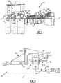
- the gear system 48 in the engine 20 is mounted on flexible couplings 74 ( Figure 2 ) to reduce loads on the gear system 48 due to misalignment with respect to the engine central axis A.
- the embodiments hereafter described resolve the aforementioned issues associated with respect to misalignment in the gear system that would otherwise result in efficiency losses in the gear teeth in the gear system and reduced life from increases in concentrated stresses.
- FIG. 2 schematically shows a portion of the engine 20 around the gear system 48.
- the gear system 48 is driven by the low speed spool 30 through an input shaft 60.
- the input shaft 60 transfers torque to the gear system 48 from the low speed spool 30.
- the input shaft 60 is coupled to a sun gear 62 of the gear system 48.
- the sun gear 62 is in meshed engagement with multiple intermediate gears 64, of which the illustrated intermediate gear 64 is representative.
- Each intermediate gear 64 is rotatably mounted in a carrier 66 by a respective rolling bearing 68, such as a journal bearing.
- Rotary motion of the sun gear 62 urges each intermediate gear 64 to rotate about a respective longitudinal axis P.
- Each intermediate gear 64 is also in meshed engagement with a ring gear 70 that is rotatably coupled to a fan shaft 72 in this example. Since the intermediate gears 64 mesh with the rotating ring gear 70 and the rotating sun gear 62, the intermediate gears 64 rotate about their own axes to drive the ring gear 70 to rotate about engine central axis A. The rotation of the ring gear 70 is conveyed to the fan 42 through the fan shaft 72 to thereby drive the fan 42 at a lower speed than the low speed spool 30.
- the carrier 66 is fixed (non-rotating) and the ring gear 70 is rotatable such that the intermediate gears 64 serve as star gears.
- the carrier 66 can alternatively be rotatable and the ring gear 70 can be fixed (non-rotating) such that the intermediate gears 64 serve as planet gears and the carrier is coupled to rotatably drive the fan shaft 72 and the fan 42.
- the flexible support 76 described herein can be coupled either to the fixed carrier (star system) or to the fixed ring gear (planetary system), depending upon the configuration of the gear system 48.
- the gear system 48 is at least partially supported by flexible couplings 74.
- the flexible couplings 74 include a first flexible coupling, which is flexible support 76 that is coupled with the carrier 66 and a second flexible coupling, which is the input shaft 60 that supports the gear system 48 with respect to bearing system 38C.
- the flexible support 76 is static (fixed, non-rotating) and supports the gear system 48 with respect to the static structure 36.
- the static structure 36 includes a bearing support static structure 78, which can also be termed a "K-frame.”
- the bearing support static structure 78 is the support structure forward of the gear system 48 that supports the bearings 38A and 38B and the fan shaft 72.
- the bearing support static structure 78 defines a lateral frame stiffness, represented as "LFS" in Figure 2 .
- the lateral frame stiffness LFS serves as a reference stiffness from which the different types of stiffnesses, described below, of the flexible couplings 74 are defined.
- the term “lateral” or variations thereof as used herein refers to a perpendicular direction with respect to the engine central axis A. It is further to be understood that "stiffness” as used herein can alternatively be termed "spring rate.”
- the stiffnesses, or spring rates are in units of pounds per inch, although conversions can be used to represent the units of pounds per inch in other units.
- the flexible couplings 74 each have one or more specific stiffnesses A, B, C, D and E, generally represented in Figure 2 at S1 and S2.
- Each of the specific stiffnesses A, B, C, D and E are defined with respect to the lateral frame stiffness LFS and a different type of motion that the flexible couplings 74 can be subject to with respect to the engine central axis A.
- the types of motion include Motion I, Motion II, Motion III, Motion IV, or combinations thereof, where Motion I is parallel offset guided end motion, Motion II is cantilever beam free end motion and Motion III is angular misalignment no offset motion and Motion IV is axial motion.
- Stiffness A is axial stiffness under Motion IV
- Stiffness B is radial stiffness under Motion II
- Stiffness C is radial stiffness under Motion I
- Stiffness D is torsional stiffness under Motion I
- Stiffness E is angular stiffness under Motion III. Terms such as “radial,” “axial,” “forward” and the like are relative to the engine central axis A.
- Motion I, Motion II, Motion III, Motion IV are schematically shown in force coupling diagrams in, respectively, Figure 3, Figure 4, Figure 5 and Figure 6 , where F represents an applied load or force and M represents a resulting moment of force.
- An applied force can also result in torsional motion, as represented in Figure 7 , as well as lateral motion.
- the term "torsion" or variations thereof as used herein refers to a twisting motion with respect to the engine central axis A.
- one or both of the flexible couplings 74 also has a torsional stiffness TS and a lateral stiffness LS defined with respect to the lateral frame stiffness LFS.
- Table 1 Types of Motion Type of Motion Description I parallel offset guided end motion II cantilever beam free end motion III angular misalignment no offset motion IV axial motion
- the torsional stiffness TS and the lateral stiffness LS of one or both of the flexible couplings 74 are selected in accordance with one another to reduce loads on the gear system 48 from misalignment of the gear system 48 with respect to the engine central axis A. That is, the torsional stiffness TS and the lateral stiffness LS of the flexible support 76 can be selected in accordance with one another, and the torsional stiffness TS and the lateral stiffness LS of the input shaft 60 can be selected in accordance with one another.
- a ratio of TS/LS is greater than or equal to about 2 for the flexible support 76, the input shaft 60 or both individually.
- the ratio of greater than or equal to about 2 provides the flexible couplings 74 with a high torsional stiffness relative to lateral stiffness such that the flexible coupling 74 is permitted to deflect or float laterally with relatively little torsional wind-up.
- the nomenclature of a ratio represented as value 1/value 2 represents value 1 divided by value 2, although the ratios herein can also be equivalently represented by other nomenclatures.
- the ratio can also be equivalently represented as 2:1 or 2/1.
- the stiffnesses herein may be provided in units of pounds per inch, although the ratios herein would be equivalent for other units.
- stiffnesses A, B, C, D, E, TS and LS can also be utilized individually or in any combination to facilitate the segregation of the gear system 48 from vibrations and other transients to reduce loads on the gear system 48 from misalignment of the gear system 48 with respect to the engine central axis A.
- the following examples further illustrate selected stiffnesses A, B, C, D, E defined with respect to the frame lateral stiffness LFS.
- a ratio of FLS/Stiffness A of the flexible support 76 is in a range of 6-25, and a ratio of FLS/Stiffness A of the input shaft 60 is in a range of 28-200.
- a ratio of FLS/Stiffness B of flexible support 76 is in a range of 10-40, and a ratio FLS/Stiffness B of the input shaft 60 is in a range of 33-1000.
- a ratio of FLS/Stiffness C of the flexible support 76 is in a range of 1.5-7, and a ratio FLS/Stiffness C of the input shaft 60 is in a range of 16-100.
- a ratio of FLS/Stiffness D of the flexible support 76 is in a range of 0.25-0.5, and a ratio FLS/Stiffness D of the input shaft 60 is in a range of 2-100.
- a ratio of FLS/Stiffness E of the flexible support 76 is in a range of 6-40, and a ratio FLS/Stiffness E of the input shaft 60 is in a range of 4-500.
- one or more of Stiffness A, Stiffness B, Stiffness C and Stiffness D of the flexible support 76 is greater than, respectively, Stiffness A, Stiffness B, Stiffness C and Stiffness D of the input shaft 60.
- the flexible support 76 and the input shaft 60 have any combination of some or all of the above-described ratios.
- the ratios are summarized in Table 2 below.
- Table 2 Ratio Ranges for First and Second Couplings Ratio FLS/Stiffness Type of Stiffness Type of Motion flexible support 76 input shaft 60 A IV 6-25 28-200 B II 10-40 33-1000 C I 1.5-7 16-100 D I 0.25-0.5 2-100 E III 6-40 4-500
Applications Claiming Priority (3)
| Application Number | Priority Date | Filing Date | Title |
|---|---|---|---|
| US201361777320P | 2013-03-12 | 2013-03-12 | |
| EP14774942.8A EP2971698B1 (fr) | 2013-03-12 | 2014-02-18 | Accouplement flexible pour turbine à engrenages |
| PCT/US2014/016753 WO2014158439A1 (fr) | 2013-03-12 | 2014-02-18 | Accouplement flexible pour turbine à engrenages |
Related Parent Applications (1)
| Application Number | Title | Priority Date | Filing Date |
|---|---|---|---|
| EP14774942.8A Division EP2971698B1 (fr) | 2013-03-12 | 2014-02-18 | Accouplement flexible pour turbine à engrenages |
Publications (1)
| Publication Number | Publication Date |
|---|---|
| EP3882448A1 true EP3882448A1 (fr) | 2021-09-22 |
Family
ID=51625009
Family Applications (2)
| Application Number | Title | Priority Date | Filing Date |
|---|---|---|---|
| EP14774942.8A Active EP2971698B1 (fr) | 2013-03-12 | 2014-02-18 | Accouplement flexible pour turbine à engrenages |
| EP21169446.8A Pending EP3882448A1 (fr) | 2013-03-12 | 2014-02-18 | Accouplement flexible pour turbine à engrenages |
Family Applications Before (1)
| Application Number | Title | Priority Date | Filing Date |
|---|---|---|---|
| EP14774942.8A Active EP2971698B1 (fr) | 2013-03-12 | 2014-02-18 | Accouplement flexible pour turbine à engrenages |
Country Status (3)
| Country | Link |
|---|---|
| US (7) | US9863326B2 (fr) |
| EP (2) | EP2971698B1 (fr) |
| WO (1) | WO2014158439A1 (fr) |
Families Citing this family (13)
| Publication number | Priority date | Publication date | Assignee | Title |
|---|---|---|---|---|
| US8900083B2 (en) * | 2011-04-27 | 2014-12-02 | United Technologies Corporation | Fan drive gear system integrated carrier and torque frame |
| EP2971698B1 (fr) * | 2013-03-12 | 2021-04-21 | Raytheon Technologies Corporation | Accouplement flexible pour turbine à engrenages |
| FR3020658B1 (fr) * | 2014-04-30 | 2020-05-15 | Safran Aircraft Engines | Capot de recuperation d'huile de lubrification pour un equipement de turbomachine |
| US10119465B2 (en) | 2015-06-23 | 2018-11-06 | United Technologies Corporation | Geared turbofan with independent flexible ring gears and oil collectors |
| GB201516571D0 (en) * | 2015-09-18 | 2015-11-04 | Rolls Royce Plc | A Coupling for a Geared Turbo Fan |
| US10094335B2 (en) | 2015-12-07 | 2018-10-09 | General Electric Company | Compliant shaft with a recursive configuration for turbine engines |
| US10590854B2 (en) * | 2016-01-26 | 2020-03-17 | United Technologies Corporation | Geared gas turbine engine |
| US10260376B2 (en) * | 2017-06-01 | 2019-04-16 | General Electric Company | Engine test stand mounting apparatus and method |
| IT201800005822A1 (it) | 2018-05-29 | 2019-11-29 | Attacco di un gruppo ingranaggio per un motore a turbina a gas | |
| US11162575B2 (en) | 2019-11-20 | 2021-11-02 | Raytheon Technologies Corporation | Geared architecture for gas turbine engine |
| GB201917781D0 (en) | 2019-12-05 | 2020-01-22 | Rolls Royce Plc | Reliable gearbox for gas turbine engine |
| GB201917783D0 (en) * | 2019-12-05 | 2020-01-22 | Rolls Royce Plc | Geared gas turbine engine |
| GB201917777D0 (en) | 2019-12-05 | 2020-01-22 | Rolls Royce Plc | High power epicyclic gearbox and operation thereof |
Citations (3)
| Publication number | Priority date | Publication date | Assignee | Title |
|---|---|---|---|---|
| US5433674A (en) * | 1994-04-12 | 1995-07-18 | United Technologies Corporation | Coupling system for a planetary gear train |
| US20100150702A1 (en) * | 2006-07-05 | 2010-06-17 | United Technologies Corporation | Flexible shaft for gas turbine engine |
| US8297916B1 (en) * | 2011-06-08 | 2012-10-30 | United Technologies Corporation | Flexible support structure for a geared architecture gas turbine engine |
Family Cites Families (111)
| Publication number | Priority date | Publication date | Assignee | Title |
|---|---|---|---|---|
| US2258792A (en) | 1941-04-12 | 1941-10-14 | Westinghouse Electric & Mfg Co | Turbine blading |
| US3021731A (en) | 1951-11-10 | 1962-02-20 | Wilhelm G Stoeckicht | Planetary gear transmission |
| US2936655A (en) | 1955-11-04 | 1960-05-17 | Gen Motors Corp | Self-aligning planetary gearing |
| US3194487A (en) | 1963-06-04 | 1965-07-13 | United Aircraft Corp | Noise abatement method and apparatus |
| US3287906A (en) | 1965-07-20 | 1966-11-29 | Gen Motors Corp | Cooled gas turbine vanes |
| US3352178A (en) | 1965-11-15 | 1967-11-14 | Gen Motors Corp | Planetary gearing |
| US3412560A (en) | 1966-08-03 | 1968-11-26 | Gen Motors Corp | Jet propulsion engine with cooled combustion chamber, fuel heater, and induced air-flow |
| US3664612A (en) | 1969-12-22 | 1972-05-23 | Boeing Co | Aircraft engine variable highlight inlet |
| GB1350431A (en) | 1971-01-08 | 1974-04-18 | Secr Defence | Gearing |
| US3892358A (en) | 1971-03-17 | 1975-07-01 | Gen Electric | Nozzle seal |
| US3765623A (en) | 1971-10-04 | 1973-10-16 | Mc Donnell Douglas Corp | Air inlet |
| US3747343A (en) | 1972-02-10 | 1973-07-24 | United Aircraft Corp | Low noise prop-fan |
| GB1418905A (en) | 1972-05-09 | 1975-12-24 | Rolls Royce | Gas turbine engines |
| US3843277A (en) | 1973-02-14 | 1974-10-22 | Gen Electric | Sound attenuating inlet duct |
| US3988889A (en) | 1974-02-25 | 1976-11-02 | General Electric Company | Cowling arrangement for a turbofan engine |
| US3932058A (en) | 1974-06-07 | 1976-01-13 | United Technologies Corporation | Control system for variable pitch fan propulsor |
| US3935558A (en) | 1974-12-11 | 1976-01-27 | United Technologies Corporation | Surge detector for turbine engines |
| US4130872A (en) | 1975-10-10 | 1978-12-19 | The United States Of America As Represented By The Secretary Of The Air Force | Method and system of controlling a jet engine for avoiding engine surge |
| GB1516041A (en) | 1977-02-14 | 1978-06-28 | Secr Defence | Multistage axial flow compressor stators |
| US4240250A (en) | 1977-12-27 | 1980-12-23 | The Boeing Company | Noise reducing air inlet for gas turbine engines |
| GB2041090A (en) | 1979-01-31 | 1980-09-03 | Rolls Royce | By-pass gas turbine engines |
| US4284174A (en) | 1979-04-18 | 1981-08-18 | Avco Corporation | Emergency oil/mist system |
| US4220171A (en) | 1979-05-14 | 1980-09-02 | The United States Of America As Represented By The Administrator Of The National Aeronautics And Space Administration | Curved centerline air intake for a gas turbine engine |
| US4289360A (en) | 1979-08-23 | 1981-09-15 | General Electric Company | Bearing damper system |
| DE2940446C2 (de) | 1979-10-05 | 1982-07-08 | B. Braun Melsungen Ag, 3508 Melsungen | Züchtung von tierischen Zellen in Suspensions- und Monolayerkulturen in Fermentationsgefäßen |
| US4478551A (en) | 1981-12-08 | 1984-10-23 | United Technologies Corporation | Turbine exhaust case design |
| US4722357A (en) | 1986-04-11 | 1988-02-02 | United Technologies Corporation | Gas turbine engine nacelle |
| US4696156A (en) * | 1986-06-03 | 1987-09-29 | United Technologies Corporation | Fuel and oil heat management system for a gas turbine engine |
| US4979362A (en) | 1989-05-17 | 1990-12-25 | Sundstrand Corporation | Aircraft engine starting and emergency power generating system |
| US5058617A (en) | 1990-07-23 | 1991-10-22 | General Electric Company | Nacelle inlet for an aircraft gas turbine engine |
| US5141400A (en) | 1991-01-25 | 1992-08-25 | General Electric Company | Wide chord fan blade |
| US5102379A (en) | 1991-03-25 | 1992-04-07 | United Technologies Corporation | Journal bearing arrangement |
| US5317877A (en) | 1992-08-03 | 1994-06-07 | General Electric Company | Intercooled turbine blade cooling air feed system |
| US5447411A (en) | 1993-06-10 | 1995-09-05 | Martin Marietta Corporation | Light weight fan blade containment system |
| US5466198A (en) | 1993-06-11 | 1995-11-14 | United Technologies Corporation | Geared drive system for a bladed propulsor |
| US5361580A (en) | 1993-06-18 | 1994-11-08 | General Electric Company | Gas turbine engine rotor support system |
| US5524847A (en) | 1993-09-07 | 1996-06-11 | United Technologies Corporation | Nacelle and mounting arrangement for an aircraft engine |
| RU2082824C1 (ru) | 1994-03-10 | 1997-06-27 | Московский государственный авиационный институт (технический университет) | Способ защиты жаропрочных материалов от воздействия агрессивных сред высокоскоростных газовых потоков (варианты) |
| US5433584A (en) * | 1994-05-05 | 1995-07-18 | Pratt & Whitney Canada, Inc. | Bearing support housing |
| US5778659A (en) | 1994-10-20 | 1998-07-14 | United Technologies Corporation | Variable area fan exhaust nozzle having mechanically separate sleeve and thrust reverser actuation systems |
| US5915917A (en) | 1994-12-14 | 1999-06-29 | United Technologies Corporation | Compressor stall and surge control using airflow asymmetry measurement |
| JP2969075B2 (ja) | 1996-02-26 | 1999-11-02 | ジャパンゴアテックス株式会社 | 脱気装置 |
| US5634767A (en) | 1996-03-29 | 1997-06-03 | General Electric Company | Turbine frame having spindle mounted liner |
| US5857836A (en) | 1996-09-10 | 1999-01-12 | Aerodyne Research, Inc. | Evaporatively cooled rotor for a gas turbine engine |
| GB2322914B (en) | 1997-03-05 | 2000-05-24 | Rolls Royce Plc | Ducted fan gas turbine engine |
| US5975841A (en) | 1997-10-03 | 1999-11-02 | Thermal Corp. | Heat pipe cooling for turbine stators |
| US5985470A (en) | 1998-03-16 | 1999-11-16 | General Electric Company | Thermal/environmental barrier coating system for silicon-based materials |
| US6260351B1 (en) | 1998-12-10 | 2001-07-17 | United Technologies Corporation | Controlled spring rate gearbox mount |
| US6517341B1 (en) | 1999-02-26 | 2003-02-11 | General Electric Company | Method to prevent recession loss of silica and silicon-containing materials in combustion gas environments |
| US6410148B1 (en) | 1999-04-15 | 2002-06-25 | General Electric Co. | Silicon based substrate with environmental/ thermal barrier layer |
| US6315815B1 (en) | 1999-12-16 | 2001-11-13 | United Technologies Corporation | Membrane based fuel deoxygenator |
| US6223616B1 (en) | 1999-12-22 | 2001-05-01 | United Technologies Corporation | Star gear system with lubrication circuit and lubrication method therefor |
| US6318070B1 (en) | 2000-03-03 | 2001-11-20 | United Technologies Corporation | Variable area nozzle for gas turbine engines driven by shape memory alloy actuators |
| US6444335B1 (en) | 2000-04-06 | 2002-09-03 | General Electric Company | Thermal/environmental barrier coating for silicon-containing materials |
| US6647707B2 (en) | 2000-09-05 | 2003-11-18 | Sudarshan Paul Dev | Nested core gas turbine engine |
| US6708482B2 (en) | 2001-11-29 | 2004-03-23 | General Electric Company | Aircraft engine with inter-turbine engine frame |
| US6663530B2 (en) | 2001-12-14 | 2003-12-16 | Pratt & Whitney Canada Corp. | Zero twist carrier |
| US6735954B2 (en) | 2001-12-21 | 2004-05-18 | Pratt & Whitney Canada Corp. | Offset drive for gas turbine engine |
| US6607165B1 (en) | 2002-06-28 | 2003-08-19 | General Electric Company | Aircraft engine mount with single thrust link |
| US6814541B2 (en) | 2002-10-07 | 2004-11-09 | General Electric Company | Jet aircraft fan case containment design |
| US7021042B2 (en) | 2002-12-13 | 2006-04-04 | United Technologies Corporation | Geartrain coupling for a turbofan engine |
| US6709492B1 (en) | 2003-04-04 | 2004-03-23 | United Technologies Corporation | Planar membrane deoxygenator |
| US6895741B2 (en) | 2003-06-23 | 2005-05-24 | Pratt & Whitney Canada Corp. | Differential geared turbine engine with torque modulation capability |
| US7104918B2 (en) | 2003-07-29 | 2006-09-12 | Pratt & Whitney Canada Corp. | Compact epicyclic gear carrier |
| DE102004016246A1 (de) | 2004-04-02 | 2005-10-20 | Mtu Aero Engines Gmbh | Turbine, insbesondere Niederdruckturbine, einer Gasturbine, insbesondere eines Flugtriebwerks |
| US7144349B2 (en) | 2004-04-06 | 2006-12-05 | Pratt & Whitney Canada Corp. | Gas turbine gearbox |
| US7328580B2 (en) | 2004-06-23 | 2008-02-12 | General Electric Company | Chevron film cooled wall |
| US7959532B2 (en) | 2004-12-01 | 2011-06-14 | United Technologies Corporation | Hydraulic seal for a gearbox of a tip turbine engine |
| GB0506685D0 (en) | 2005-04-01 | 2005-05-11 | Hopkins David R | A design to increase and smoothly improve the throughput of fluid (air or gas) through the inlet fan (or fans) of an aero-engine system |
| US7374403B2 (en) | 2005-04-07 | 2008-05-20 | General Electric Company | Low solidity turbofan |
| US8772398B2 (en) | 2005-09-28 | 2014-07-08 | Entrotech Composites, Llc | Linerless prepregs, composite articles therefrom, and related methods |
| US7493754B2 (en) * | 2005-10-19 | 2009-02-24 | General Electric Company | Gas turbine engine assembly and methods of assembling same |
| US20080097813A1 (en) | 2005-12-28 | 2008-04-24 | Collins Robert J | System and method for optimizing advertisement campaigns according to advertiser specified business objectives |
| US7591754B2 (en) | 2006-03-22 | 2009-09-22 | United Technologies Corporation | Epicyclic gear train integral sun gear coupling design |
| BE1017135A3 (nl) | 2006-05-11 | 2008-03-04 | Hansen Transmissions Int | Een tandwielkast voor een windturbine. |
| ES2571786T3 (es) * | 2006-06-09 | 2016-05-26 | Vestas Wind Sys As | Turbina eólica que comprende un amortiguador de torsión |
| US20080003096A1 (en) | 2006-06-29 | 2008-01-03 | United Technologies Corporation | High coverage cooling hole shape |
| JP4911344B2 (ja) | 2006-07-04 | 2012-04-04 | 株式会社Ihi | ターボファンエンジン |
| US7704178B2 (en) | 2006-07-05 | 2010-04-27 | United Technologies Corporation | Oil baffle for gas turbine fan drive gear system |
| US8585538B2 (en) | 2006-07-05 | 2013-11-19 | United Technologies Corporation | Coupling system for a star gear train in a gas turbine engine |
| US7632064B2 (en) | 2006-09-01 | 2009-12-15 | United Technologies Corporation | Variable geometry guide vane for a gas turbine engine |
| US7662059B2 (en) | 2006-10-18 | 2010-02-16 | United Technologies Corporation | Lubrication of windmilling journal bearings |
| US7832193B2 (en) * | 2006-10-27 | 2010-11-16 | General Electric Company | Gas turbine engine assembly and methods of assembling same |
| US7841165B2 (en) | 2006-10-31 | 2010-11-30 | General Electric Company | Gas turbine engine assembly and methods of assembling same |
| US7841163B2 (en) | 2006-11-13 | 2010-11-30 | Hamilton Sundstrand Corporation | Turbofan emergency generator |
| US8020665B2 (en) | 2006-11-22 | 2011-09-20 | United Technologies Corporation | Lubrication system with extended emergency operability |
| US8017188B2 (en) | 2007-04-17 | 2011-09-13 | General Electric Company | Methods of making articles having toughened and untoughened regions |
| US7950237B2 (en) | 2007-06-25 | 2011-05-31 | United Technologies Corporation | Managing spool bearing load using variable area flow nozzle |
| US20120124964A1 (en) | 2007-07-27 | 2012-05-24 | Hasel Karl L | Gas turbine engine with improved fuel efficiency |
| US8256707B2 (en) | 2007-08-01 | 2012-09-04 | United Technologies Corporation | Engine mounting configuration for a turbofan gas turbine engine |
| US7942635B1 (en) | 2007-08-02 | 2011-05-17 | Florida Turbine Technologies, Inc. | Twin spool rotor assembly for a small gas turbine engine |
| US8205432B2 (en) | 2007-10-03 | 2012-06-26 | United Technologies Corporation | Epicyclic gear train for turbo fan engine |
| GB0807775D0 (en) | 2008-04-29 | 2008-06-04 | Romax Technology Ltd | Methods for model-based diagnosis of gearbox |
| US8128021B2 (en) | 2008-06-02 | 2012-03-06 | United Technologies Corporation | Engine mount system for a turbofan gas turbine engine |
| US7997868B1 (en) | 2008-11-18 | 2011-08-16 | Florida Turbine Technologies, Inc. | Film cooling hole for turbine airfoil |
| US8307626B2 (en) | 2009-02-26 | 2012-11-13 | United Technologies Corporation | Auxiliary pump system for fan drive gear system |
| US8181441B2 (en) | 2009-02-27 | 2012-05-22 | United Technologies Corporation | Controlled fan stream flow bypass |
| US8172716B2 (en) | 2009-06-25 | 2012-05-08 | United Technologies Corporation | Epicyclic gear system with superfinished journal bearing |
| CN101995510B (zh) * | 2009-08-19 | 2012-11-07 | 胜德国际研发股份有限公司 | 电源指示结构 |
| US9170616B2 (en) | 2009-12-31 | 2015-10-27 | Intel Corporation | Quiet system cooling using coupled optimization between integrated micro porous absorbers and rotors |
| US8905713B2 (en) | 2010-05-28 | 2014-12-09 | General Electric Company | Articles which include chevron film cooling holes, and related processes |
| US9631558B2 (en) * | 2012-01-03 | 2017-04-25 | United Technologies Corporation | Geared architecture for high speed and small volume fan drive turbine |
| US8814503B2 (en) * | 2011-06-08 | 2014-08-26 | United Technologies Corporation | Flexible support structure for a geared architecture gas turbine engine |
| US8172717B2 (en) | 2011-06-08 | 2012-05-08 | General Electric Company | Compliant carrier wall for improved gearbox load sharing |
| US9410608B2 (en) * | 2011-06-08 | 2016-08-09 | United Technologies Corporation | Flexible support structure for a geared architecture gas turbine engine |
| US9133729B1 (en) * | 2011-06-08 | 2015-09-15 | United Technologies Corporation | Flexible support structure for a geared architecture gas turbine engine |
| US9239012B2 (en) * | 2011-06-08 | 2016-01-19 | United Technologies Corporation | Flexible support structure for a geared architecture gas turbine engine |
| US20130192196A1 (en) * | 2012-01-31 | 2013-08-01 | Gabriel L. Suciu | Gas turbine engine with high speed low pressure turbine section |
| US8529197B1 (en) * | 2012-03-28 | 2013-09-10 | United Technologies Corporation | Gas turbine engine fan drive gear system damper |
| EP2971698B1 (fr) * | 2013-03-12 | 2021-04-21 | Raytheon Technologies Corporation | Accouplement flexible pour turbine à engrenages |
| US10590854B2 (en) * | 2016-01-26 | 2020-03-17 | United Technologies Corporation | Geared gas turbine engine |
-
2014
- 2014-02-18 EP EP14774942.8A patent/EP2971698B1/fr active Active
- 2014-02-18 WO PCT/US2014/016753 patent/WO2014158439A1/fr active Application Filing
- 2014-02-18 US US14/766,766 patent/US9863326B2/en active Active
- 2014-02-18 EP EP21169446.8A patent/EP3882448A1/fr active Pending
-
2018
- 2018-01-05 US US15/862,716 patent/US10087850B2/en active Active
- 2018-01-05 US US15/862,777 patent/US10087851B2/en active Active
- 2018-10-01 US US16/148,239 patent/US10787971B2/en active Active
- 2018-10-01 US US16/148,217 patent/US10787970B2/en active Active
-
2020
- 2020-09-28 US US17/034,713 patent/US11136920B2/en active Active
-
2021
- 2021-09-21 US US17/480,503 patent/US11536203B2/en active Active
Patent Citations (5)
| Publication number | Priority date | Publication date | Assignee | Title |
|---|---|---|---|---|
| US5433674A (en) * | 1994-04-12 | 1995-07-18 | United Technologies Corporation | Coupling system for a planetary gear train |
| US20100150702A1 (en) * | 2006-07-05 | 2010-06-17 | United Technologies Corporation | Flexible shaft for gas turbine engine |
| US8297916B1 (en) * | 2011-06-08 | 2012-10-30 | United Technologies Corporation | Flexible support structure for a geared architecture gas turbine engine |
| US8297917B1 (en) * | 2011-06-08 | 2012-10-30 | United Technologies Corporation | Flexible support structure for a geared architecture gas turbine engine |
| EP2532841A2 (fr) * | 2011-06-08 | 2012-12-12 | United Technologies Corporation | Structure de support flexible pour moteur de turbine à gaz à architecture à engrenages |
Also Published As
| Publication number | Publication date |
|---|---|
| US20190032572A1 (en) | 2019-01-31 |
| US10787971B2 (en) | 2020-09-29 |
| WO2014158439A1 (fr) | 2014-10-02 |
| US11536203B2 (en) | 2022-12-27 |
| US11136920B2 (en) | 2021-10-05 |
| EP2971698B1 (fr) | 2021-04-21 |
| EP2971698A1 (fr) | 2016-01-20 |
| US20180128185A1 (en) | 2018-05-10 |
| US20220003172A1 (en) | 2022-01-06 |
| US20210010428A1 (en) | 2021-01-14 |
| US10087850B2 (en) | 2018-10-02 |
| US10787970B2 (en) | 2020-09-29 |
| US20200232391A9 (en) | 2020-07-23 |
| US20180128186A1 (en) | 2018-05-10 |
| US9863326B2 (en) | 2018-01-09 |
| US20150377143A1 (en) | 2015-12-31 |
| US20190032570A1 (en) | 2019-01-31 |
| EP2971698A4 (fr) | 2016-11-09 |
| US10087851B2 (en) | 2018-10-02 |
Similar Documents
| Publication | Publication Date | Title |
|---|---|---|
| US11536203B2 (en) | Flexible coupling for geared turbine engine | |
| US11698007B2 (en) | Flexible support structure for a geared architecture gas turbine engine | |
| EP3097275B1 (fr) | Structure de support flexible pour un moteur à turbine à gaz à architecture à engrenages | |
| EP2899389A1 (fr) | Structure de support flexible pour moteur de turbine à gaz à architecture à engrenages | |
| EP3048284A1 (fr) | Structure de support flexible pour moteur de turbine à gaz à architecture à engrenages |
Legal Events
| Date | Code | Title | Description |
|---|---|---|---|
| PUAI | Public reference made under article 153(3) epc to a published international application that has entered the european phase |
Free format text: ORIGINAL CODE: 0009012 |
|
| STAA | Information on the status of an ep patent application or granted ep patent |
Free format text: STATUS: THE APPLICATION HAS BEEN PUBLISHED |
|
| AC | Divisional application: reference to earlier application |
Ref document number: 2971698 Country of ref document: EP Kind code of ref document: P |
|
| AK | Designated contracting states |
Kind code of ref document: A1 Designated state(s): AL AT BE BG CH CY CZ DE DK EE ES FI FR GB GR HR HU IE IS IT LI LT LU LV MC MK MT NL NO PL PT RO RS SE SI SK SM TR |
|
| STAA | Information on the status of an ep patent application or granted ep patent |
Free format text: STATUS: REQUEST FOR EXAMINATION WAS MADE |
|
| 17P | Request for examination filed |
Effective date: 20220322 |
|
| RBV | Designated contracting states (corrected) |
Designated state(s): AL AT BE BG CH CY CZ DE DK EE ES FI FR GB GR HR HU IE IS IT LI LT LU LV MC MK MT NL NO PL PT RO RS SE SI SK SM TR |
|
| RAP3 | Party data changed (applicant data changed or rights of an application transferred) |
Owner name: RTX CORPORATION |
|
| GRAP | Despatch of communication of intention to grant a patent |
Free format text: ORIGINAL CODE: EPIDOSNIGR1 |
|
| STAA | Information on the status of an ep patent application or granted ep patent |
Free format text: STATUS: GRANT OF PATENT IS INTENDED |
|
| INTG | Intention to grant announced |
Effective date: 20240202 |