EP2899389A1 - Structure de support flexible pour moteur de turbine à gaz à architecture à engrenages - Google Patents
Structure de support flexible pour moteur de turbine à gaz à architecture à engrenages Download PDFInfo
- Publication number
- EP2899389A1 EP2899389A1 EP15152745.4A EP15152745A EP2899389A1 EP 2899389 A1 EP2899389 A1 EP 2899389A1 EP 15152745 A EP15152745 A EP 15152745A EP 2899389 A1 EP2899389 A1 EP 2899389A1
- Authority
- EP
- European Patent Office
- Prior art keywords
- lateral stiffness
- gear
- gear system
- support
- input
- Prior art date
- Legal status (The legal status is an assumption and is not a legal conclusion. Google has not performed a legal analysis and makes no representation as to the accuracy of the status listed.)
- Withdrawn
Links
Images


Classifications
-
- F—MECHANICAL ENGINEERING; LIGHTING; HEATING; WEAPONS; BLASTING
- F02—COMBUSTION ENGINES; HOT-GAS OR COMBUSTION-PRODUCT ENGINE PLANTS
- F02K—JET-PROPULSION PLANTS
- F02K3/00—Plants including a gas turbine driving a compressor or a ducted fan
- F02K3/02—Plants including a gas turbine driving a compressor or a ducted fan in which part of the working fluid by-passes the turbine and combustion chamber
- F02K3/04—Plants including a gas turbine driving a compressor or a ducted fan in which part of the working fluid by-passes the turbine and combustion chamber the plant including ducted fans, i.e. fans with high volume, low pressure outputs, for augmenting the jet thrust, e.g. of double-flow type
- F02K3/077—Plants including a gas turbine driving a compressor or a ducted fan in which part of the working fluid by-passes the turbine and combustion chamber the plant including ducted fans, i.e. fans with high volume, low pressure outputs, for augmenting the jet thrust, e.g. of double-flow type the plant being of the multiple flow type, i.e. having three or more flows
-
- F—MECHANICAL ENGINEERING; LIGHTING; HEATING; WEAPONS; BLASTING
- F02—COMBUSTION ENGINES; HOT-GAS OR COMBUSTION-PRODUCT ENGINE PLANTS
- F02C—GAS-TURBINE PLANTS; AIR INTAKES FOR JET-PROPULSION PLANTS; CONTROLLING FUEL SUPPLY IN AIR-BREATHING JET-PROPULSION PLANTS
- F02C7/00—Features, components parts, details or accessories, not provided for in, or of interest apart form groups F02C1/00 - F02C6/00; Air intakes for jet-propulsion plants
- F02C7/36—Power transmission arrangements between the different shafts of the gas turbine plant, or between the gas-turbine plant and the power user
-
- F—MECHANICAL ENGINEERING; LIGHTING; HEATING; WEAPONS; BLASTING
- F05—INDEXING SCHEMES RELATING TO ENGINES OR PUMPS IN VARIOUS SUBCLASSES OF CLASSES F01-F04
- F05D—INDEXING SCHEME FOR ASPECTS RELATING TO NON-POSITIVE-DISPLACEMENT MACHINES OR ENGINES, GAS-TURBINES OR JET-PROPULSION PLANTS
- F05D2240/00—Components
- F05D2240/60—Shafts
- F05D2240/62—Flexible
-
- F—MECHANICAL ENGINEERING; LIGHTING; HEATING; WEAPONS; BLASTING
- F05—INDEXING SCHEMES RELATING TO ENGINES OR PUMPS IN VARIOUS SUBCLASSES OF CLASSES F01-F04
- F05D—INDEXING SCHEME FOR ASPECTS RELATING TO NON-POSITIVE-DISPLACEMENT MACHINES OR ENGINES, GAS-TURBINES OR JET-PROPULSION PLANTS
- F05D2260/00—Function
- F05D2260/40—Transmission of power
- F05D2260/403—Transmission of power through the shape of the drive components
- F05D2260/4031—Transmission of power through the shape of the drive components as in toothed gearing
- F05D2260/40311—Transmission of power through the shape of the drive components as in toothed gearing of the epicyclical, planetary or differential type
-
- F—MECHANICAL ENGINEERING; LIGHTING; HEATING; WEAPONS; BLASTING
- F05—INDEXING SCHEMES RELATING TO ENGINES OR PUMPS IN VARIOUS SUBCLASSES OF CLASSES F01-F04
- F05D—INDEXING SCHEME FOR ASPECTS RELATING TO NON-POSITIVE-DISPLACEMENT MACHINES OR ENGINES, GAS-TURBINES OR JET-PROPULSION PLANTS
- F05D2300/00—Materials; Properties thereof
- F05D2300/50—Intrinsic material properties or characteristics
- F05D2300/501—Elasticity
-
- Y—GENERAL TAGGING OF NEW TECHNOLOGICAL DEVELOPMENTS; GENERAL TAGGING OF CROSS-SECTIONAL TECHNOLOGIES SPANNING OVER SEVERAL SECTIONS OF THE IPC; TECHNICAL SUBJECTS COVERED BY FORMER USPC CROSS-REFERENCE ART COLLECTIONS [XRACs] AND DIGESTS
- Y02—TECHNOLOGIES OR APPLICATIONS FOR MITIGATION OR ADAPTATION AGAINST CLIMATE CHANGE
- Y02T—CLIMATE CHANGE MITIGATION TECHNOLOGIES RELATED TO TRANSPORTATION
- Y02T50/00—Aeronautics or air transport
- Y02T50/60—Efficient propulsion technologies, e.g. for aircraft
Definitions
- the present disclosure relates to a gas turbine engine, and more particularly to a flexible support structure for a geared architecture therefor.
- Planetary and star gear trains may be used in gas turbine engines for their compact designs and efficient high gear reduction capabilities.
- Planetary and star gear trains generally include three gear train elements: a central sun gear, an outer ring gear with internal gear teeth, and a plurality of planet gears supported by a planet carrier between and in meshed engagement with both the sun gear and the ring gear.
- the gear train elements share a common longitudinal central axis, about which at least two rotate.
- the central sun gear In gas turbine engine applications, where a speed reduction transmission is required, the central sun gear generally receives rotary input from the power plant, the outer ring gear is generally held stationary and the planet gear carrier rotates in the same direction as the sun gear to provide torque output at a reduced rotational speed.
- the planet carrier In star gear trains, the planet carrier is held stationary and the output shaft is driven by the ring gear in a direction opposite that of the sun gear.
- a gas turbine engine in a featured embodiment, includes a fan shaft and a support which supports the fan shaft.
- the support may define a support lateral stiffness.
- a gear system drives the fan shaft.
- a flexible support at least partially supports the gear system, and may define a flexible support lateral stiffness with respect to the support lateral stiffness.
- An input to the gear system may define an input lateral stiffness with respect to the support lateral stiffness.
- the support and the flexible support are mounted to a static structure.
- the support and the flexible support are mounted to a static structure of a gas turbine engine.
- the support and the flexible support are mounted to a front center body of a gas turbine engine.
- the flexible support is mounted to a planet carrier of the gear system.
- the input is mounted to a sun gear of the gear system.
- the fan shaft is mounted to a ring gear of the gear system.
- the gear system is a star system.
- the flexible support is mounted to a ring gear of the gear system.
- the input is mounted to a sun gear of the gear system.
- the fan shaft is mounted to a planet carrier of the gear system.
- the gear system is a planet system.
- a low speed spool drives the input.
- the flexible support lateral stiffness and the input lateral stiffness are both less than the support lateral stiffness.
- At least one of the flexible support lateral stiffness and the input lateral stiffness is less than about 20% of the support lateral stiffness.
- the flexible support lateral stiffness and the input lateral stiffness are each less than about 20% of the support lateral stiffness.
- At least one of the flexible support lateral stiffness and the input lateral stiffness is less than about 11% of the support lateral stiffness.
- the flexible support lateral stiffness and the input lateral stiffness are each less than about 11% of the support lateral stiffness.
- a turbine provides an input to the gear system.
- the gear system further drives a compressor rotor at a common speed with the fan shaft.
- a turbine section drives the gear system and at least two compressor rotors.
- a fan drive turbine drives the gear system.
- At least two other turbines drive at least two compressor rotors.
- a gas turbine engine in another featured embodiment, includes a fan shaft and a support which supports the fan shaft.
- a gear system drives the fan shaft and includes a gear mesh that may define a gear mesh lateral stiffness.
- a flexible support at least partially supports the gear system, and may define a flexible support lateral stiffness with respect to the gear mesh lateral stiffness.
- An input to the gear system may define an input lateral stiffness with respect to the gear mesh lateral stiffness.
- both the flexible support lateral stiffness and the input lateral stiffness are less than the gear mesh lateral stiffness.
- the flexible support lateral stiffness is less than about 8% of the gear mesh lateral stiffness.
- the input lateral stiffness is less than about 5% of the gear mesh lateral stiffness.
- a lateral stiffness of a ring gear of the gear system is less than about 20% of the gear mesh lateral stiffness.
- a lateral stiffness of a ring gear of the gear system is less than about 12% of the gear mesh lateral stiffness.
- a lateral stiffness of a planet journal bearing which supports a planet gear of the gear system is less than or equal to the gear mesh lateral stiffness.
- a method of designing a gas turbine engine includes providing a fan shaft, and a support which supports the fan shaft.
- the support may define a support lateral stiffness.
- a gear system drives the fan shaft.
- a flexible support at least partially supports the gear system, and may define a flexible support lateral stiffness with respect to the support lateral stiffness.
- An input may define an input lateral stiffness with respect to the support lateral stiffness.
- the embodiment in another embodiment according to the previous embodiment, includes a turbine section to drive the gear system and at least two compressor rotors.
- a fan drive turbine drives the gear system.
- At least two other turbines drive at least two compressor rotors.
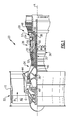
- FIG. 1 schematically illustrates a gas turbine engine 20.
- the gas turbine engine 20 is disclosed herein as a two-spool turbofan that generally incorporates a fan section 22, a compressor section 24, a combustor section 26 and a turbine section 28.
- Alternative engines might include an augmentor section (not shown) among other systems or features.
- the fan section 22 drives air along a bypass flow path B in a bypass duct defined within a nacelle 15, while the compressor section 24 drives air along a core flow path C for compression and communication into the combustor section 26 then expansion through the turbine section 28.
- the exemplary engine 20 generally includes a low speed spool 30 and a high speed spool 32 mounted for rotation about an engine central longitudinal axis A relative to an engine static structure 36 via several bearing systems 38. It should be understood that various bearing systems 38 at various locations may alternatively or additionally be provided, and the location of bearing systems 38 may be varied as appropriate to the application.
- the low speed spool 30 generally includes an inner shaft 40 that interconnects a fan 42, a first (or low) pressure compressor 44 and a first (or low) pressure turbine 46.
- the inner shaft 40 is connected to the fan 42 through a speed change mechanism, which in exemplary gas turbine engine 20 is illustrated as a geared architecture 48 to drive the fan 42 at a lower speed than the low speed spool 30.
- the high speed spool 32 includes an outer shaft 50 that interconnects a second (or high) pressure compressor 52 and a second (or high) pressure turbine 54.
- a combustor 56 is arranged in exemplary gas turbine 20 between the high pressure compressor 52 and the high pressure turbine 54.
- a mid-turbine frame 57 of the engine static structure 36 is arranged generally between the high pressure turbine 54 and the low pressure turbine 46.
- the mid-turbine frame 57 further supports bearing systems 38 in the turbine section 28.
- the inner shaft 40 and the outer shaft 50 are concentric and rotate via bearing systems 38 about the engine central longitudinal axis A which is collinear with their longitudinal axes.
- the core airflow is compressed by the low pressure compressor 44 then the high pressure compressor 52, mixed and burned with fuel in the combustor 56, then expanded over the high pressure turbine 54 and low pressure turbine 46.
- the mid-turbine frame 57 includes airfoils 59 which are in the core airflow path C.
- the turbines 46, 54 rotationally drive the respective low speed spool 30 and high speed spool 32 in response to the expansion.
- gear system 48 may be located aft of combustor section 26 or even aft of turbine section 28, and fan section 22 may be positioned forward or aft of the location of gear system 48.
- the engine 20 in one example is a high-bypass geared aircraft engine.
- the engine 20 bypass ratio is greater than about six (6), with an example embodiment being greater than about ten (10)
- the geared architecture 48 is an epicyclic gear train, such as a planetary gear system or other gear system, with a gear reduction ratio of greater than about 2.3
- the low pressure turbine 46 has a pressure ratio that is greater than about five.
- the engine 20 bypass ratio is greater than about ten (10:1)
- the fan diameter is significantly larger than that of the low pressure compressor 44
- the low pressure turbine 46 has a pressure ratio that is greater than about five 5:1.
- Low pressure turbine 46 pressure ratio is pressure measured prior to inlet of low pressure turbine 46 as related to the pressure at the outlet of the low pressure turbine 46 prior to an exhaust nozzle.
- the geared architecture 48 may be an epicycle gear train, such as a planetary gear system or other gear system, with a gear reduction ratio of greater than about 2.3:1. It should be understood, however, that the above parameters are only exemplary of one embodiment of a geared architecture engine and that the present invention is applicable to other gas turbine engines including direct drive turbofans.
- the fan section 22 of the engine 20 is designed for a particular flight condition -- typically cruise at about 0.8 Mach and about 35,000 feet (10668 m).
- "Low fan pressure ratio” is the pressure ratio across the fan blade alone, without a Fan Exit Guide Vane (“FEGV”) system.
- the low fan pressure ratio as disclosed herein according to one non-limiting embodiment is less than about 1.45.
- the "Low corrected fan tip speed” as disclosed herein according to one non-limiting embodiment is less than about 1150 ft / second (350.5 m/s).
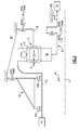
- the geared architecture 48 generally includes a fan drive gear system (FDGS) 60 driven by the low speed spool 30 (illustrated schematically) through an input 62.
- the input 62 which may be in the form of a coupling, both transfers torque from the low speed spool 30 to the geared architecture 48 and facilitates the segregation of vibrations and other transients therebetween.
- the FDGS 60 may include an epicyclic gear system which may be, for example, a star system or a planet system.
- the input coupling 62 may include an interface spline 64 joined, by a gear spline 66, to a sun gear 68 of the FDGS 60.
- the sun gear 68 is in meshed engagement with multiple planet gears 70, of which the illustrated planet gear 70 is representative.
- Each planet gear 70 is rotatably mounted in a planet carrier 72 by a respective planet journal bearing 75. Rotary motion of the sun gear 68 urges each planet gear 70 to rotate about a respective longitudinal axis P.
- Each planet gear 70 is also in meshed engagement with rotating ring gear 74 that is mechanically connected to a fan shaft 76. Since the planet gears 70 mesh with both the rotating ring gear 74 as well as the rotating sun gear 68, the planet gears 70 rotate about their own axes to drive the ring gear 74 to rotate about engine axis A. The rotation of the ring gear 74 is conveyed to the fan 42 ( Figure 1 ) through the fan shaft 76 to thereby drive the fan 42 at a lower speed than the low speed spool 30. It should be understood that the described geared architecture 48 is but a single non-limiting embodiment and that various other geared architectures will alternatively benefit herefrom.
- a flexible support 78 supports the planet carrier 72 to at least partially support the FDGS 60A with respect to the static structure 36 such as a front center body which facilitates the segregation of vibrations and other transients therebetween.
- the static structure 36 such as a front center body which facilitates the segregation of vibrations and other transients therebetween.
- various gas turbine engine case structures may alternatively or additionally provide the static structure and flexible support 78.
- lateral as defined herein is generally transverse to the axis of rotation A which typically absorbs transverse deflection which may be otherwise applied to the FDGS 60.
- the static structure 36 may further include a number 1 and 1.5 bearing support static structure 82 which is commonly referred to as a "K-frame" which supports the number 1 and number 1.5 bearing systems 38A. 38B.
- the K-frame bearing support defines a lateral stiffness (Kframe) as the referenced factor in this non-limiting embodiment.
- the lateral stiffness (KFS; KIC) of both the flexible support 78 and the input coupling 62 are each less than about 11% of the lateral stiffness (Kframe). That is, the lateral stiffness of the entire FDGS 60 is controlled by this relationship.
- a FDGS 60B includes a flexible support 78' that supports a rotationally fixed ring gear 74'.
- the fan shaft 76' is driven by the planet carrier 72' in the schematically illustrated planet system which otherwise generally follows the star system architecture of Figure 3 .
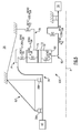
- lateral stiffness relationship within a FDGS 60C itself is schematically represented.
- the lateral stiffness (KIC) of an input coupling 62, a lateral stiffness (KFS) of a flexible support 78, a lateral stiffness (KRG) of a ring gear 74 and a lateral stiffness (KJB) of a planet journal bearing 75 are controlled with respect to a lateral stiffness (KGM) of a gear mesh within the FDGS 60.
- the stiffness (KGM) may be defined by the gear mesh between the sun gear 68 and the multiple planet gears 70.
- the lateral stiffness (KGM) within the FDGS 60 is the referenced factor and the static structure 82' rigidly supports the fan shaft 76. That is, the fan shaft 76 is supported upon bearing systems 38A, 38B which are essentially rigidly supported by the static structure 82'.
- the lateral stiffness (KJB) may be mechanically defined by, for example, the stiffness within the planet journal bearing 75 and the lateral stiffness (KRG) of the ring gear 74 may be mechanically defined by, for example, the geometry of the ring gear wings 74L, 74R ( Figure 2 ).
- the lateral stiffness (KRG) of the ring gear 74 is less than about 12% of the lateral stiffness (KGM) of the gear mesh; the lateral stiffness (KFS) of the flexible support 78 is less than about 8% of the lateral stiffness (KGM) of the gear mesh; the lateral stiffness (KJB) of the planet journal bearing 75 is less than or equal to the lateral stiffness (KGM) of the gear mesh; and the lateral stiffness (KIC) of an input coupling 62 is less than about 5% of the lateral stiffness (KGM) of the gear mesh.
- FIG. 6 another non-limiting embodiment of a lateral stiffness relationship within a FDGS 60D itself are schematically illustrated for a planetary gear system architecture, which otherwise generally follows the star system architecture of Figure 5 .
- lateral stiffness relationships may be utilized as well.
- the lateral stiffness of each of structural components may be readily measured as compared to film stiffness and spline stiffness which may be relatively difficult to determine.
- the flex mount facilitates alignment to increase system life and reliability.
- the lateral flexibility in the flexible support and input coupling allows the FDGS to essentially 'float' with the fan shaft during maneuvers. This allows: (a) the torque transmissions in the fan shaft, the input coupling and the flexible support to remain constant during maneuvers; (b) maneuver induced lateral loads in the fan shaft (which may otherwise potentially misalign gears and damage teeth) to be mainly reacted to through the number 1 and 1.5 bearing support K-frame; and (c) both the flexible support and the input coupling to transmit small amounts of lateral loads into the FDGS.
- the splines, gear tooth stiffness, journal bearings, and ring gear ligaments are specifically designed to minimize gear tooth stress variations during maneuvers.
- the other connections to the FDGS are flexible mounts (turbine coupling, case flex mount). These mount spring rates have been determined from analysis and proven in rig and flight testing to isolate the gears from engine maneuver loads.
- the planet journal bearing spring rate may also be controlled to support system flexibility.
- Figure 7 shows an embodiment 200, wherein there is a fan drive turbine 208 driving a shaft 206 to in turn drive a fan rotor 202.
- a gear reduction 204 may be positioned between the fan drive turbine 208 and the fan rotor 202.
- This gear reduction 204 may be structured, mounted and operate like the gear reduction disclosed above.
- a compressor rotor 210 is driven by an intermediate pressure turbine 212, and a second stage compressor rotor 214 is driven by a turbine rotor 216.
- a combustion section 218 is positioned intermediate the compressor rotor 214 and the turbine section 216.
- Figure 8 shows yet another embodiment 300 wherein a fan rotor 302 and a first stage compressor 304 rotate at a common speed.
- the gear reduction 306 (which may be structured, mounted and operate as disclosed above) is intermediate the compressor rotor 304 and a shaft 308, which is driven by a low pressure turbine section.
Applications Claiming Priority (1)
| Application Number | Priority Date | Filing Date | Title |
|---|---|---|---|
| US14/164,364 US8814503B2 (en) | 2011-06-08 | 2014-01-27 | Flexible support structure for a geared architecture gas turbine engine |
Publications (1)
| Publication Number | Publication Date |
|---|---|
| EP2899389A1 true EP2899389A1 (fr) | 2015-07-29 |
Family
ID=52394995
Family Applications (1)
| Application Number | Title | Priority Date | Filing Date |
|---|---|---|---|
| EP15152745.4A Withdrawn EP2899389A1 (fr) | 2014-01-27 | 2015-01-27 | Structure de support flexible pour moteur de turbine à gaz à architecture à engrenages |
Country Status (1)
| Country | Link |
|---|---|
| EP (1) | EP2899389A1 (fr) |
Cited By (1)
| Publication number | Priority date | Publication date | Assignee | Title |
|---|---|---|---|---|
| CN110469407A (zh) * | 2018-05-11 | 2019-11-19 | 通用电气公司 | 用于齿轮涡轮机的支撑结构 |
Citations (3)
| Publication number | Priority date | Publication date | Assignee | Title |
|---|---|---|---|---|
| US8297916B1 (en) * | 2011-06-08 | 2012-10-30 | United Technologies Corporation | Flexible support structure for a geared architecture gas turbine engine |
| EP2551488A2 (fr) * | 2011-07-29 | 2013-01-30 | United Technologies Corporation | Configuration de paliers pour moteur triple corps |
| US20130224003A1 (en) * | 2012-02-28 | 2013-08-29 | Daniel Bernard Kupratis | Gas turbine engine with fan-tied inducer section |
-
2015
- 2015-01-27 EP EP15152745.4A patent/EP2899389A1/fr not_active Withdrawn
Patent Citations (3)
| Publication number | Priority date | Publication date | Assignee | Title |
|---|---|---|---|---|
| US8297916B1 (en) * | 2011-06-08 | 2012-10-30 | United Technologies Corporation | Flexible support structure for a geared architecture gas turbine engine |
| EP2551488A2 (fr) * | 2011-07-29 | 2013-01-30 | United Technologies Corporation | Configuration de paliers pour moteur triple corps |
| US20130224003A1 (en) * | 2012-02-28 | 2013-08-29 | Daniel Bernard Kupratis | Gas turbine engine with fan-tied inducer section |
Cited By (2)
| Publication number | Priority date | Publication date | Assignee | Title |
|---|---|---|---|---|
| CN110469407A (zh) * | 2018-05-11 | 2019-11-19 | 通用电气公司 | 用于齿轮涡轮机的支撑结构 |
| CN110469407B (zh) * | 2018-05-11 | 2022-02-15 | 通用电气公司 | 用于齿轮涡轮机的支撑结构 |
Similar Documents
| Publication | Publication Date | Title |
|---|---|---|
| US11698007B2 (en) | Flexible support structure for a geared architecture gas turbine engine | |
| US8814503B2 (en) | Flexible support structure for a geared architecture gas turbine engine | |
| EP3045684B1 (fr) | Structure de support flexible pour moteur de turbine à gaz à architecture à engrenages | |
| EP3051078A1 (fr) | Structure de support flexible pour moteur de turbine à gaz à architecture à engrenages | |
| US8770922B2 (en) | Flexible support structure for a geared architecture gas turbine engine | |
| EP4209661A2 (fr) | Architecture à engrenages pour turbine d'entraînement de ventilateur à grande vitesse et à petit volume | |
| EP3097275B1 (fr) | Structure de support flexible pour un moteur à turbine à gaz à architecture à engrenages | |
| EP2899389A1 (fr) | Structure de support flexible pour moteur de turbine à gaz à architecture à engrenages | |
| EP3048284A1 (fr) | Structure de support flexible pour moteur de turbine à gaz à architecture à engrenages |
Legal Events
| Date | Code | Title | Description |
|---|---|---|---|
| PUAI | Public reference made under article 153(3) epc to a published international application that has entered the european phase |
Free format text: ORIGINAL CODE: 0009012 |
|
| 17P | Request for examination filed |
Effective date: 20150127 |
|
| AK | Designated contracting states |
Kind code of ref document: A1 Designated state(s): AL AT BE BG CH CY CZ DE DK EE ES FI FR GB GR HR HU IE IS IT LI LT LU LV MC MK MT NL NO PL PT RO RS SE SI SK SM TR |
|
| AX | Request for extension of the european patent |
Extension state: BA ME |
|
| 17P | Request for examination filed |
Effective date: 20160129 |
|
| RBV | Designated contracting states (corrected) |
Designated state(s): AL AT BE BG CH CY CZ DE DK EE ES FI FR GB GR HR HU IE IS IT LI LT LU LV MC MK MT NL NO PL PT RO RS SE SI SK SM TR |
|
| 17Q | First examination report despatched |
Effective date: 20160613 |
|
| RAP1 | Party data changed (applicant data changed or rights of an application transferred) |
Owner name: UNITED TECHNOLOGIES CORPORATION |
|
| STAA | Information on the status of an ep patent application or granted ep patent |
Free format text: STATUS: THE APPLICATION HAS BEEN WITHDRAWN |
|
| 18W | Application withdrawn |
Effective date: 20200218 |