EP3882214A1 - Apparatus and method for manufacturing aerogel blanket - Google Patents
Apparatus and method for manufacturing aerogel blanket Download PDFInfo
- Publication number
- EP3882214A1 EP3882214A1 EP20860326.6A EP20860326A EP3882214A1 EP 3882214 A1 EP3882214 A1 EP 3882214A1 EP 20860326 A EP20860326 A EP 20860326A EP 3882214 A1 EP3882214 A1 EP 3882214A1
- Authority
- EP
- European Patent Office
- Prior art keywords
- blanket
- bobbin
- gelling
- silica sol
- gelling tank
- Prior art date
- Legal status (The legal status is an assumption and is not a legal conclusion. Google has not performed a legal analysis and makes no representation as to the accuracy of the status listed.)
- Granted
Links
Images




Classifications
-
- B—PERFORMING OPERATIONS; TRANSPORTING
- B01—PHYSICAL OR CHEMICAL PROCESSES OR APPARATUS IN GENERAL
- B01J—CHEMICAL OR PHYSICAL PROCESSES, e.g. CATALYSIS OR COLLOID CHEMISTRY; THEIR RELEVANT APPARATUS
- B01J13/00—Colloid chemistry, e.g. the production of colloidal materials or their solutions, not otherwise provided for; Making microcapsules or microballoons
- B01J13/0091—Preparation of aerogels, e.g. xerogels
-
- B—PERFORMING OPERATIONS; TRANSPORTING
- B28—WORKING CEMENT, CLAY, OR STONE
- B28B—SHAPING CLAY OR OTHER CERAMIC COMPOSITIONS; SHAPING SLAG; SHAPING MIXTURES CONTAINING CEMENTITIOUS MATERIAL, e.g. PLASTER
- B28B1/00—Producing shaped prefabricated articles from the material
- B28B1/30—Producing shaped prefabricated articles from the material by applying the material on to a core or other moulding surface to form a layer thereon
- B28B1/38—Producing shaped prefabricated articles from the material by applying the material on to a core or other moulding surface to form a layer thereon by dipping
-
- B—PERFORMING OPERATIONS; TRANSPORTING
- B28—WORKING CEMENT, CLAY, OR STONE
- B28B—SHAPING CLAY OR OTHER CERAMIC COMPOSITIONS; SHAPING SLAG; SHAPING MIXTURES CONTAINING CEMENTITIOUS MATERIAL, e.g. PLASTER
- B28B1/00—Producing shaped prefabricated articles from the material
- B28B1/30—Producing shaped prefabricated articles from the material by applying the material on to a core or other moulding surface to form a layer thereon
- B28B1/40—Producing shaped prefabricated articles from the material by applying the material on to a core or other moulding surface to form a layer thereon by wrapping, e.g. winding
-
- B—PERFORMING OPERATIONS; TRANSPORTING
- B28—WORKING CEMENT, CLAY, OR STONE
- B28B—SHAPING CLAY OR OTHER CERAMIC COMPOSITIONS; SHAPING SLAG; SHAPING MIXTURES CONTAINING CEMENTITIOUS MATERIAL, e.g. PLASTER
- B28B1/00—Producing shaped prefabricated articles from the material
- B28B1/52—Producing shaped prefabricated articles from the material specially adapted for producing articles from mixtures containing fibres, e.g. asbestos cement
-
- B—PERFORMING OPERATIONS; TRANSPORTING
- B28—WORKING CEMENT, CLAY, OR STONE
- B28B—SHAPING CLAY OR OTHER CERAMIC COMPOSITIONS; SHAPING SLAG; SHAPING MIXTURES CONTAINING CEMENTITIOUS MATERIAL, e.g. PLASTER
- B28B1/00—Producing shaped prefabricated articles from the material
- B28B1/52—Producing shaped prefabricated articles from the material specially adapted for producing articles from mixtures containing fibres, e.g. asbestos cement
- B28B1/525—Producing shaped prefabricated articles from the material specially adapted for producing articles from mixtures containing fibres, e.g. asbestos cement containing organic fibres, e.g. wood fibres
-
- B—PERFORMING OPERATIONS; TRANSPORTING
- B28—WORKING CEMENT, CLAY, OR STONE
- B28B—SHAPING CLAY OR OTHER CERAMIC COMPOSITIONS; SHAPING SLAG; SHAPING MIXTURES CONTAINING CEMENTITIOUS MATERIAL, e.g. PLASTER
- B28B11/00—Apparatus or processes for treating or working the shaped or preshaped articles
- B28B11/24—Apparatus or processes for treating or working the shaped or preshaped articles for curing, setting or hardening
-
- B—PERFORMING OPERATIONS; TRANSPORTING
- B28—WORKING CEMENT, CLAY, OR STONE
- B28B—SHAPING CLAY OR OTHER CERAMIC COMPOSITIONS; SHAPING SLAG; SHAPING MIXTURES CONTAINING CEMENTITIOUS MATERIAL, e.g. PLASTER
- B28B17/00—Details of, or accessories for, apparatus for shaping the material; Auxiliary measures taken in connection with such shaping
- B28B17/02—Conditioning the material prior to shaping
-
- B—PERFORMING OPERATIONS; TRANSPORTING
- B28—WORKING CEMENT, CLAY, OR STONE
- B28B—SHAPING CLAY OR OTHER CERAMIC COMPOSITIONS; SHAPING SLAG; SHAPING MIXTURES CONTAINING CEMENTITIOUS MATERIAL, e.g. PLASTER
- B28B21/00—Methods or machines specially adapted for the production of tubular articles
- B28B21/02—Methods or machines specially adapted for the production of tubular articles by casting into moulds
-
- B—PERFORMING OPERATIONS; TRANSPORTING
- B28—WORKING CEMENT, CLAY, OR STONE
- B28B—SHAPING CLAY OR OTHER CERAMIC COMPOSITIONS; SHAPING SLAG; SHAPING MIXTURES CONTAINING CEMENTITIOUS MATERIAL, e.g. PLASTER
- B28B21/00—Methods or machines specially adapted for the production of tubular articles
- B28B21/42—Methods or machines specially adapted for the production of tubular articles by shaping on or against mandrels or like moulding surfaces
- B28B21/46—Methods or machines specially adapted for the production of tubular articles by shaping on or against mandrels or like moulding surfaces by dipping
-
- B—PERFORMING OPERATIONS; TRANSPORTING
- B28—WORKING CEMENT, CLAY, OR STONE
- B28B—SHAPING CLAY OR OTHER CERAMIC COMPOSITIONS; SHAPING SLAG; SHAPING MIXTURES CONTAINING CEMENTITIOUS MATERIAL, e.g. PLASTER
- B28B21/00—Methods or machines specially adapted for the production of tubular articles
- B28B21/56—Methods or machines specially adapted for the production of tubular articles incorporating reinforcements or inserts
-
- B—PERFORMING OPERATIONS; TRANSPORTING
- B28—WORKING CEMENT, CLAY, OR STONE
- B28B—SHAPING CLAY OR OTHER CERAMIC COMPOSITIONS; SHAPING SLAG; SHAPING MIXTURES CONTAINING CEMENTITIOUS MATERIAL, e.g. PLASTER
- B28B21/00—Methods or machines specially adapted for the production of tubular articles
- B28B21/70—Methods or machines specially adapted for the production of tubular articles by building-up from preformed elements
-
- B—PERFORMING OPERATIONS; TRANSPORTING
- B28—WORKING CEMENT, CLAY, OR STONE
- B28B—SHAPING CLAY OR OTHER CERAMIC COMPOSITIONS; SHAPING SLAG; SHAPING MIXTURES CONTAINING CEMENTITIOUS MATERIAL, e.g. PLASTER
- B28B21/00—Methods or machines specially adapted for the production of tubular articles
- B28B21/92—Methods or apparatus for treating or reshaping
- B28B21/94—Methods or apparatus for treating or reshaping for impregnating or coating by applying liquids or semi-liquids
-
- C—CHEMISTRY; METALLURGY
- C01—INORGANIC CHEMISTRY
- C01B—NON-METALLIC ELEMENTS; COMPOUNDS THEREOF; METALLOIDS OR COMPOUNDS THEREOF NOT COVERED BY SUBCLASS C01C
- C01B33/00—Silicon; Compounds thereof
- C01B33/113—Silicon oxides; Hydrates thereof
- C01B33/12—Silica; Hydrates thereof, e.g. lepidoic silicic acid
- C01B33/14—Colloidal silica, e.g. dispersions, gels, sols
- C01B33/145—Preparation of hydroorganosols, organosols or dispersions in an organic medium
-
- C—CHEMISTRY; METALLURGY
- C01—INORGANIC CHEMISTRY
- C01B—NON-METALLIC ELEMENTS; COMPOUNDS THEREOF; METALLOIDS OR COMPOUNDS THEREOF NOT COVERED BY SUBCLASS C01C
- C01B33/00—Silicon; Compounds thereof
- C01B33/113—Silicon oxides; Hydrates thereof
- C01B33/12—Silica; Hydrates thereof, e.g. lepidoic silicic acid
- C01B33/14—Colloidal silica, e.g. dispersions, gels, sols
- C01B33/155—Preparation of hydroorganogels or organogels
-
- C—CHEMISTRY; METALLURGY
- C01—INORGANIC CHEMISTRY
- C01B—NON-METALLIC ELEMENTS; COMPOUNDS THEREOF; METALLOIDS OR COMPOUNDS THEREOF NOT COVERED BY SUBCLASS C01C
- C01B33/00—Silicon; Compounds thereof
- C01B33/113—Silicon oxides; Hydrates thereof
- C01B33/12—Silica; Hydrates thereof, e.g. lepidoic silicic acid
- C01B33/14—Colloidal silica, e.g. dispersions, gels, sols
- C01B33/157—After-treatment of gels
- C01B33/158—Purification; Drying; Dehydrating
-
- C—CHEMISTRY; METALLURGY
- C01—INORGANIC CHEMISTRY
- C01B—NON-METALLIC ELEMENTS; COMPOUNDS THEREOF; METALLOIDS OR COMPOUNDS THEREOF NOT COVERED BY SUBCLASS C01C
- C01B33/00—Silicon; Compounds thereof
- C01B33/113—Silicon oxides; Hydrates thereof
- C01B33/12—Silica; Hydrates thereof, e.g. lepidoic silicic acid
- C01B33/14—Colloidal silica, e.g. dispersions, gels, sols
- C01B33/157—After-treatment of gels
- C01B33/158—Purification; Drying; Dehydrating
- C01B33/1585—Dehydration into aerogels
-
- C—CHEMISTRY; METALLURGY
- C01—INORGANIC CHEMISTRY
- C01B—NON-METALLIC ELEMENTS; COMPOUNDS THEREOF; METALLOIDS OR COMPOUNDS THEREOF NOT COVERED BY SUBCLASS C01C
- C01B33/00—Silicon; Compounds thereof
- C01B33/113—Silicon oxides; Hydrates thereof
- C01B33/12—Silica; Hydrates thereof, e.g. lepidoic silicic acid
- C01B33/14—Colloidal silica, e.g. dispersions, gels, sols
- C01B33/157—After-treatment of gels
- C01B33/159—Coating or hydrophobisation
Definitions
- the present invention relates to an apparatus and method for preparing an aerogel blanket, and more particularly, to an apparatus and method for preparing an aerogel blanket, which are capable of improving productivity of the aerogel blanket.
- aerogel is a material having a high specific surface area ( ⁇ 500m 2 /g) with a porosity of about 90% to about 99.9% and a pore size ranging of 1 nm to 100 nm. Since the aerogel has characteristics such as excellent lightweight/ultra-insulation/ultra-low dielectric properties, studies on the development of aerogel materials and application studies on transparent insulation materials, environmentally friendly high-temperature insulation materials, ultra-low dielectric thin film materials for highly integrated devices, materials for catalysts and catalyst carriers, electrode materials for super capacitors, and electrode materials for seawater desalination.
- the above-described aerogel may be combined with fibers so as to be commercialized in the form such as an aerogel blanket or aerogel sheet.
- the blanket or sheet since the blanket or sheet has flexibility, the blanket or sheet may be bent, folded, or cut in a predetermined size or shape.
- the aerogel may be applied not only to industrial applications such as insulation panels for LNG carriers, industrial insulation materials, and insulation materials for space suits, transportation and vehicles, and power generation, but also to household goods such as jackets and sneakers.
- the aerogel is used for fire doors as well as roofs or floors in the house such as apartments, there is a great effect in preventing fire.
- the aerogel blanket is a material in which aerogel is impregnated and is prepared by mixing and gelling silica sol in the blanket.
- the present invention has been invented to solve the above problems, and an object of the present invention is to provide an apparatus and method for preparing an aerogel blanket, which are capable of improving productivity of the aerogel blanket to mass-produce the aerogel blanket.
- An apparatus for preparing an aerogel blanket according to the present invention for achieving the above object comprises: a bobbin around which a blanket is wound; a main body provided with a gelling tank in which the bobbin is accommodated; a driving member configured to allow the bobbin accommodated in the gelling tank to rotate; and a silica sol supply member configured to gelate the blanket as silica sol is injected into the gelling tank to impregnate the blanket rotating by the bobbin.
- the bobbin may comprise a winding rod around which the blanket is wound in the roll shape and a support plate coupled to both ends of the winding rod to support a side portion of the blanket wound around the winding rod.
- the winding rod may have an inner portion in which a hollow, into which the silica sol injected into the gelling tank is introduced, is defined and an outer portion in which a plurality of connection holes, through which the silica sol introduced into the hollow is discharged to the outside of the winding rod so as to be impregnated into the blanket wound around the winding rod, are defined.
- a plurality of opening holes may be defined in the support plate.
- the gelling tank may comprise a gelling chamber that is provided inside the gelling tank to accommodate the bobbin, a discharge part provided at an outer lower end of the gelling tank and connected to the gelling chamber, and an inflow part provided at an outer upper end of the gelling tank and connected to the gelling chamber, and the gelling chamber may have a U-shaped cross-sectional shape of which an upper portion is opened by a cover.
- the gelling tank may comprise a rotation member provided on both wall surfaces of the gelling chamber and coupled to both ends of the bobbin so that the bobbin is rotatably installed in the gelling chamber.
- a coupling groove may be defined in each of both ends of the bobbin, and a coupling protrusion may be disposed on the rotation member, and the bobbin and the rotation member may be interlocked with each other to rotate by coupling of the coupling groove and the coupling protrusion.
- the driving member may allow the bobbin to rotate through one rotation member provided in the gelling tank.
- the gelling tank may comprise a rotation handle coupled to the other rotation member provided in the gelling tank to allow the bobbin to rotate.
- a method for preparing an aerogel blanket according to the present invention comprises: a winding step (S10) of winding a blanket around a bobbin; an accommodation step (S20) in which the bobbin around which the blanket is wound is rotatably installed inside a gelling tank; a silica sol preparation step (S30) of injecting a precursor solution and a catalyst solution into a silica sol supply member to mix the precursor solution and the catalyst solution with each other, thereby preparing silica sol; a rotation step (S40) of allowing the bobbin, around which the blanket is wound, to rotate through a driving member; and a gelation step (S50) of injecting the silica sol mixed in the silica sol supply member into the gelling tank to impregnate the silica sol into the blanket rotating by the bobbin, thereby gelating the blanket. the silica sol into the blanket rotating by the bobbin, thereby gelating the blanket.
- the blanket may be gelated while the bobbin rotates at a speed of 15 rpm to 325 rpm, preferably, a speed of 30 rpm to 200 rpm.
- the silica sol may be injected to an amount of 80% to 120% based on a volume of the blanket.
- the method may further comprises, after the gelation step (S50), a collection step (S60) of collecting the silica sol remaining in the gelling tank.
- the method may further comprises, after the collection step (S60), an aging step (S70) of injecting an aging solution into the gelling tank to age the blanket rotating by the bobbin and to collect the aging solution remaining in the gelling tank when the aging of the blanket is completed.
- the method may further comprises, after the aging step (S70), a surface modifying step (S80) of injecting a surface modifying solution into the gelling tank to modify a surface of the blanket rotating by the bobbin and to collect the surface modifying solution remaining in the gelling tank when the surface modification of the blanket is completed.
- the method may further comprises, after the surface modifying step (S80), a drying step (S90) of drying the blanket to complete the aerogel blanket.
- the bobbin around which the blanket is wound when the bobbin around which the blanket is wound is accommodated in the gelling chamber of the gelling tank, and both ends of the bobbin are coupled to a rotation member that is rotatably provided on both wall surfaces of the gelling chamber, the bobbin around which the blanket is wound may be rotatably installed inside the gelling tank.
- the apparatus for preparing the aerogel blanket may comprise the bobbin, the main body provided with the gelling tank, the driving member, and the silica sol supply member. That is, the silica sol may be impregnated to be gelated, aged, surface-modified, and dried in the state in which the blanket rotates in the gelling tank. Due to these characteristics, the time taken to prepare the aerogel blanket may be significantly reduced. Therefore, the productivity of the aerogel blanket may be significantly improved to facilitate the mass-production of the aerogel blanket. Particularly, the blanket may rotate to uniformly gelate the entire blanket.
- the bobbin may comprise the winding rod and the support plate. Due to these features, the blanket may be stably wound around the bobbin. Particularly, the blanket may be wound at the same position through the support plate to improve the efficiency in work.
- the winding rod may comprise the hollow and the plurality of connection holes. Due to these features, the silica sol may be effectively introduced into the inside of the blanket wound around the winding rod. Therefore, the inside of the blanket may be stably gelated, and thus, the entire blanket may be uniformly gelated, and the time taken to gelate the blanket may be significantly reduced.
- the support plate may comprise the plurality of opening holes. Due to these features, the silica sol may be introduced into the side portion of the blanket wound around the winding rod. Therefore, the side portion of the blanket may be stably gelated to uniformly gelate the entire blanket and significantly reduce the gelation time of the blanket.
- the gelling tank may have the U-shaped cross-section. Due to these features, the contact force between the silica sol stored on the bottom of the gelling tank and the blanket may be improved, and thus, the injected sol may be impregnated into the blanket to minimize the consumption of the sol and improve the gelation of the blanket. That is, the space between the bottom of the gelling tank and the blanket may be minimized to induce the impregnation of all the sol into the blanket.
- the gelling tank may comprise the rotation member that is configured to rotatably install the bobbin. Due to these features, the bobbin may stably rotate in the gelling tank.
- the bobbin and the rotation member may be coupled to each other through the coupling groove and the coupling protrusion. Due to this feature, the rotation member and the bobbin may be easily connected to or separated from each other to improve the efficiency in work.
- an apparatus for preparing an aerogel blanket comprises a bobbin 100 around which a blanket 10 is wound, a main body 200 provided with a gelling tank 210 in which the bobbin 100 is accommodated, a driving member 300 configured to allow the bobbin 100 accommodated in the gelling tank 210 to rotate, a silica sol supply member 400 configured to gelate the blanket 10 as silica sol 20 is injected into the gelling tank 210 so as to be mixed into the blanket 10 that rotates by the bobbin 100, an aging member 500 that ages the blanket 10, which rotates by the bobbin 100, by injecting an aging solution into the gelling tank 210, a surface modifying member 600 that modifies a surface of the blanket 10 by injecting a surface modifying solution into the gelling tank 210, and a drying member 700 in which the gelling tank 210 increases in temperature to dry the blanket 10 that rotates by the bobbin 100.
- the bobbin 100 is configured to wind the blanket in a roll shape and comprises a winding rod 110 around which the blanket 10 is wound in the roll shape and a support plate 120 coupled to both ends of the winding rod 110 to support a side portion of the blanket 10 wound around the winding rod 110.
- the winding rod 110 has a cylindrical shape with a hollow 111 that is penetrated in a longitudinal direction, and the blanket 10 having a long sheet shape is wound around an outer surface of the winding rod 110.
- the silica sol may be quickly impregnated into an outer portion of the blanket 10 wound around the winding rod 110 to stably gelate the blanket 10. However, it is taken for a long time to impregnate an inner portion of the blanket 10 by using the silica sol. To prevent this problem, a plurality of connection holes 112 connected to the hollow 111 are defined in an outer circumferential surface of the winding rod 110.
- the hollow 111 may be defined in the winding rod 110 so that the silica sol injected into the gelling tank 210 is introduced.
- the plurality of connection holes 112, through which the silica sol introduced into the hollow 111 is discharged out of the winding rod 110 is impregnated into the inner portion of the blanket 10 wound around the winding rod 110 so as to be impregnated into the inner portion of the blanket 10 wound around the winding rod 110, are defined in the winding rod 110.
- the inner portion and the outer portion of the blanket 10 may be gelated at the same time by impregnating the silica sol. Therefore, a time taken to gelate the blanket 10 may be significantly reduced to uniformly gelate the entire blanket 10.
- Each of the plurality of connection holes 112 has a diameter of 3 mm to 5 mm, and the plurality of connection holes 112 are defined at regular intervals in the outer circumferential surface of the winding rod 110.
- the silica sol may be uniformly supplied to the entire blanket 10 wound around the outer circumferential surface of the winding rod 110 to uniformly gelate the entire inside of the blanket 10.
- the support plate 120 is configured to support the blanket wound around the winding rod 110 so that the blanket is not irregularly wound.
- the support plate 120 has a disc shape and is coupled to both ends of the winding rod 110 to support the side portion of the blanket 10 wound around the winding rod 110.
- the support plate 120 comprises a coupling groove 121, to which an end of the winding rod 110 is coupled, and a coupling hole 122 defined in a bottom surface of the coupling groove 121. That is, the support plate 120 may be coupled to the end of the winding rod 110 through the coupling groove 121.
- a plurality of opening holes 123 may be defined in the support plate 120.
- the silica sol may be introduced into the side portion of the blanket 10 wound around the winding rod 110 through the plurality of opening holes 123, and thus, the side portion of the blanket 10 may be stably gelated.
- the bobbin 100 comprises the winding rod 110 and the support plate 120 to wind the blanket in the roll shape.
- the main body 200 is configured to install the gelling tank in which the bobbin is accommodated and comprises the gelling tank 210 and a first installation member 220 on which the gelling tank 210 is installed.
- the gelling tank 210 is configured to gelate the blanket accommodated in the bobbin and comprises a gelling chamber 211 that is provided inside the gelling tank 210 to accommodate the bobbin 100, a discharge part 212 provided at an outer lower end of the gelling tank 210 and connected to the gelling chamber 211, and an inflow part 213 provided at an outer upper end of the gelling tank 210 and connected to the gelling chamber 211.
- the gelling chamber 211 of the gelling tank 210 has a U-shaped cross-sectional shape of which an upper portion is opened by a cover 214, and a lower portion has a curvature corresponding to that blanket 10 wound around the winding rod 110.
- contact force between the silica sol and the blanket 10 may increase to improve gelation of the blanket 10.
- the gelling tank 210 comprises a rotation member 215 provided on both wall surfaces of the gelling chamber 211 and coupled to both ends of the bobbin 100 so that the bobbin 100 is rotatably installed in the gelling chamber 211.
- the rotation member 215 is rotatably installed in a through-hole defined in each of both the wall surfaces of the gelling chamber so that the end of the bobbin 100 accommodated in the gelling chamber 211 is capable of transmitting power.
- a coupling protrusion 215a having a straight-line shape is disposed on one surface of the rotation member 215, and a coupling groove 124 having a straight-line shape and coupled to the coupling protrusion 215a is defined in the end of the bobbin 100. That is, when the rotation member 215 rotates the bobbin 100 may rotate in the same direction through the coupling of the coupling protrusion 215a and the coupling groove 124. As a result, the bobbin 100 may be rotatably installed inside the gelling tank 210.
- the main body 200 further comprises a second installation member 230 on which the silica sol supply member 400 is installed.
- the second installation member 230 comprises a bottom piece 231, an installation frame 232 installed on an upper portion of the bottom piece 231 and installed so that the silica sol supply member 400 is disposed higher than that gelling tank 210, and a stair 233 installed on an end of one side of the bottom piece 231.
- the gelling tank comprises a rotation handle 216 coupled to the other rotation member 215 (the left rotation member when viewed in FIG. 1 ) provided in the gelling tank to allow the bobbin to rotate.
- the rotation handle 216 may allow the bobbin 100 to manually rotate at the outside.
- the aging member 500, the surface modifying member 600, and the drying member 700 are further installed on the installation frame 232 of the second installation member 230.
- the driving member 300 is configured to allow the bobbin accommodated in the gelling tank to rotate.
- the driving member 300 is connected to the other rotation member 215 (the right rotation member when viewed in FIG. 1 ) provided in the gelling tank 210 to transmit power. That is, when the rotation member 215 rotates, the driving member 300 may be interlocked with the rotation member 215 to allow the bobbin 100 accommodated in the gelling tank 210 to rotate.
- the silica sol supply member 400 is configured to gelate the blanket by injecting the silica sol into the gelling tank to impregnate the blanket wound around the bobbin.
- the silica sol supply member 400 is installed on the installation frame 232 to supply the silica sol into the gelling chamber 211 through the inflow part 213 of the gelling tank 210.
- the aging member 500 is configured to age the blanket wound around the bobbin.
- the aging member 500 is installed on the installation frame 232 to supply an aging solution into the gelling chamber 211 through the inflow part 213 of the gelling tank 210.
- the surface modifying member 600 is configured to inject a surface modifying solution into the gelling tank so as to modify the surface of the blanket.
- the surface modifying member 600 is installed on the installation frame 232 to supply the surface modifying solution into the gelling tank 210 through the inflow part 213.
- the drying member 700 is configured to supply high-temperature hot air into the gelling tank so as to dry the blanket wound around the bobbin.
- the drying member 700 is installed on the installation frame 232 and rises a temperature of the gelling tank 210 to dry the blanket 10 accommodated in the gelling tank 210.
- the time taken to prepare the aerogel blanket may be significantly reduced, and the productivity of the aerogel blanket may be significantly improved to mass-produce the aerogel blanket.
- the apparatus for preparing the aerogel blanket according to the first embodiment of the present invention may induce the stable gelation regardless of a thickness and length of the blanket as the blanket rotates. Since the bobbin rotates, the entire blanket wound around the bobbin may be uniformly gelated. Also, since only the bobbin rotates without the gelling tank does not rotate, the gelling tank is not limited in shape. Also, since the gelling chamber of the gelling tank has the 'U'-shaped cross-sectional shape, the blanket wound around the bobbin may be more effectively gelated.
- a method for preparing the aerogel blanket according to the first embodiment of the present invention comprises a winding step (S10) of winding a blanket 10 around a bobbin 100, an accommodation step (S20) in which the bobbin 100 around which the blanket 10 is wound is rotatably installed inside a gelling tank 210 of a main body 200, a silica sol preparation step (S30) of injecting a precursor solution and a catalyst solution into a silica sol supply member 300 to mix the precursor solution and the catalyst solution with each other, thereby preparing silica sol, a rotation step (S40) of allowing the bobbin 100, around which the blanket 10 is wound, to rotate through a driving member 400, a gelation step (S50) of injecting the silica sol mixed in the silica sol supply member into the gelling tank 210 to impregnate the silica sol into the blanket 10 rotating by the bobbin 100, thereby gelating the blanket 10,
- the blanket 10 is wound in a roll shape by using the bobbin 100. That is, the blanket 10 is wound in the roll shape in a state of locating a start point of the blanket 10 at a winding rod 110 of the bobbin 100.
- a side portion of the blanket 10 wound around the winding rod 110 may be wound uniformly as being supported by a support plate 120.
- the blanket may be a porous base material in terms of improving heat insulating properties of the aerogel blanket.
- the catalyzed sol may be easily penetrated into the base material to uniformly form the aerogel in the blanket.
- the prepared aerogel blanket may have excellent thermal insulation properties.
- the blanket may be a film, a sheet, a net, fiber, foam, nonwoven fabric, or a laminate having two or more layers thereof.
- surface roughness may be formed or patterned on the surface of the blanket according to application of the blanket. More particularly, the blanket may comprise a space or pore, through which the aerogel is easily injected, to improve thermal insulation performance. It may be preferable that the blanket has low thermal conductivity.
- the blanket may be polyamide, polybenzimidazole, polyaramid, an acrylic resin, a phenol resin, polyester, polyether ether ketone (PEEK), polyolefin (for example, polyethylene, polypropylene, or a copolymer thereof), cellulose, carbon, cotton, wool, hemp, non-woven fabric, glass fiber, or ceramic wool, and more specifically, the blanket may be glass fiber (glass felt).
- PEEK polyether ether ketone
- polyolefin for example, polyethylene, polypropylene, or a copolymer thereof
- the blanket may be glass fiber (glass felt).
- the bobbin 100 around which the blanket 10 is wound is rotatably installed inside the gelling tank 210 provided in the man body 200. That is, the bobbin 100 is accommodated in the gelling tank 210, and then, both ends of the bobbin 100 are installed on the rotation members 215 provided on both wall surfaces of the gelling tank 210, respectively.
- the bobbin 100 may rotate by being interlocked with the rotation member 215. That is, when the rotation member 215 rotates, the bobbin 100 may be interlocked with the rotation member 215 to rotate. Since the bobbin 100 rotates, the blanket 10 may also rotate.
- the precursor solution and the catalyst solution are injected into the silica sol supply member 300 and then mixed with each other to prepare catalyzed silica sol.
- the catalyzed silica sol may be prepared by mixing sol with a base catalyst, and the base catalyst allows the sol to increase in pH, thereby promoting gelation.
- the silica sol is not limited as long as the silica sol is a material capable of forming porous gel by a sol-gel reaction.
- the silica sol may comprise inorganic sol, organic sol, or a combination thereof.
- the inorganic sol may comprise zirconia, yttrium oxide, hafnia, alumina, titania, ceria, silica, magnesium oxide, calcium oxide, magnesium fluoride, calcium fluoride and combinations thereof
- the organic sol may comprise polyacrylate, polyolefin, polystyrene, polyacrylonitrile, polyurethane, polyimide, polyfurfural alcohol, phenol furfuryl alcohol, melamine formaldehyde, resorcinol formaldehyde, cresol formaldehyde, phenol formaldehyde, polyvinyl alcohol dialdehyde, polysianurates, polyacrylamides, various epoxies, agar, agarose, and combinations thereof.
- the silica sol may be prepared by mixing a silica precursor material with alcohol. Also, the silica sol may undergo hydrolysis at a low pH to facilitate the gelation.
- the precursor solution which is the silica precursor usable for the preparation of the silica sol
- the silica precursor according to an embodiment of the present invention may be tetraethyl orthosilicate (TEOS).
- the precursor solution which is the silica precursor, may be used in an amount so that a content of silica (SiO 2 ) contained in the silica sol ranges of 3% wt% to 30% wt%. If the content of the silica is less than 3 wt%, a content of the silica aerogel in the finally prepared blanket is too low to cause a problem that a desired level of a thermal insulation effect is not expected. If the content of the silica exceeds 30 wt%, there is a fear that the silica aerogel is excessively formed to deteriorate mechanical properties of the blanket, particularly, flexibility of the blanket.
- alcohol that is capable of being used for the preparation of the silica sol may comprise monohydric alcohol such as methanol, ethanol, isopropanol and butanol; polyhydric alcohol such as glycerol, ethylene glycol, propylene glycol, diethylene glycol, dipropylene glycol, and sorbitol, or a mixture of two or more of the above materials.
- monohydric alcohol such as methanol, ethanol, isopropanol and butanol
- polyhydric alcohol such as glycerol, ethylene glycol, propylene glycol, diethylene glycol, dipropylene glycol, and sorbitol, or a mixture of two or more of the above materials.
- monohydric alcohol having 1 to 6 carbon atoms such as methanol, ethanol, isopropanol, butanol, and the like may be used.
- the precursor solution which is the silica precursor, and water are contained at a molar ratio of 1:4 to 1:1.
- the silica precursor and the alcohol may be contained at a weight ratio of 1:2 to 1:9 and preferably may be contained at a weight ratio of 1:4 to 1:6.
- the base catalysts usable in the catalyzed silica sol may be inorganic bases such as sodium hydroxide and potassium hydroxide; or organic bases such as ammonium hydroxide.
- the base catalysts may be one or more selected from the group consisting of sodium hydroxide (NaOH), potassium hydroxide (KOH), calcium hydroxide (Ca(OH) 2 ), ammonia (NH 3 ), ammonium hydroxide (NH 4 OH), tetramethylammonium hydroxide (TMAH), tetraethylammonium hydroxide (TEAH), tetrapropylammonium hydroxide (TPAH), tetrabutylammonium hydroxide (TBAH), methylamine, ethylamine, isopropylamine, monoisopropylamine, diethylamine, diisopropylamine, dibutylamine, trimethylamine, triethylamine, triisopropylamine, tributylamine,
- the base catalyst may be contained in an amount so that the sol has a pH of 7 to 11.
- the pH of the silica sol is out of the above range, the gelation may not be easy, or a gelation rate may be too slow to deteriorate processability.
- the base since the base is precipitated when being put into a solid phase, it may be preferable to be added in a solution phase that is diluted with the above-mentioned alcohol (a polar organic solvent).
- a dilution ratio of the base catalyst and the alcohol may be 1:4 to 1:100 based on a volume.
- the precursor solution is prepared by mixing an alkoxide-based silica precursor with water and ethanol in the silica sol supply member 300.
- the silica precursor is tetraethyl orthosilicate (TEOS)
- TEOS and ethanol are diluted to have a weight ratio of 1:5, and then, TEOS and water are mixed at a molar ratio of 1:4.
- TEOS is hydrolyzed.
- hydrochloric acid is added so that the silica precursor solution has a pH of 3 or less to promote the hydrolysis.
- an opacifying agent and a flame retardant corresponding to a weight ratio of 0 to 1 of the precursor solution are put into the precursor solution and stirred for 30 minutes.
- 0 to 10 vol% of an ammonia ethanol solution (base catalyst solution) is mixed with the precursor solution to prepare the silica sol.
- the rotation member 215 of the gelling tank 210 rotates through the driving member 300.
- the bobbin 100 accommodated in the gelling tank 210 may rotate through the rotation member 215, and the blanket 10 wound around the bobbin 100 in the roll shape may rotate inside the gelling tank 210 by the rotation of the bobbin 100.
- the bobbin 100 may stably rotate by two rotation members 215 provided in the gelling tank 210.
- the silica sol mixed in the silica sol supply member 300 is supplied through an inflow part 213 of the gelling tank 210.
- the silica sol supplied to the gelling tank 210 may be impregnated into the blanket 10 wound around the bobbin 100 to gelate the blanket 10.
- the blanket 10 wound around the bobbin 100 rotates, the entire blanket 10 may be uniformly gelated.
- the silica sol remaining in the gelling chamber 211 is discharged to the outside through the discharge part 212 of the gelling tank 210 and then is collected.
- an aging solution 500 of the aging member 500 is injected through the inflow part 213 of the gelling tank 210 to age the blanket 10 rotating by the bobbin 100. That is, 1% to 10 vol% of ammonia and ethanol solution are injected to the gelling tank 210, and the gelling tank 210 is aged for 25 minutes to 100 minutes while the gelling tank is maintained at a temperature at 25°C to 80°C.
- the aging solution remaining in the gelling chamber 211 is collected through the discharge part 212 of the gelling tank 210.
- the blanket 10 may be maintained in the rotating state due to the bobbin 100 to effectively age the surface of the blanket 10.
- a surface modification solution of the surface modifying member 600 is injected into the gelling tank 210 to modify the surface of the blanket 10 rotating by the bobbin 100. That is, to modify the surface of the blanket 10, the surface modification is performed for 1 hour to 24 hours at 1 vol% to 10 vol% of a hexamethyldisilazane (HMDS) ethanol diluted solution.
- HMDS hexamethyldisilazane
- the surface modifying solution remaining in the gelling tank 210 is collected.
- the blanket 10 may be maintained in the rotating state due to the bobbin 100 to more effectively modify the surface of the blanket 10.
- a temperature inside the gelling tank 210 increases through the drying member 700 to dry the blanket 10 accommodated in the gelling tank 210, thereby completing the aerogel blanket. That is, CO 2 is injected through the inflow part 213 of the gelling tank 210, a temperature of the gelling tank 210 increases to 60°C over 1 hour, and supercritical drying is performed at a temperature of 60°C and a pressure of 100 bar. Ambient drying is performed on the blanket 10 for 2 hours in a state in which the gelling tank 210, in which the supercritical drying is completed, increases to a temperature of 200°C to completely remove residual salt and moisture. Thus, a hydrophobic silica aerogel blanket may be prepared.
- the entire blanket 10 may be uniformly dried.
- the silica sol in the blanket may be gelated, aged, surface-modified, and dried in the gelling tank to prepare a finished product aerogel blanket.
- an apparatus for preparing an aerogel blanket according to a second embodiment of the present invention comprises a bobbin 100 around which a blanket 10 is wound, and the bobbin 100 comprises a winding rod 110 and a support plate 120.
- a fixing clip 113 into which a winding start point of the blanket 10 is fitted and fixed is provided on an outer circumferential surface of the winding rod 110.
- the fixing clip 113 has a pin shape having elastic restoring force and has one end fixed to the outer circumferential surface of the winding rod 110 and the other end that is elastically supported on an outer circumferential surface of the winding rod 110. Therefore, when the start point of the blanket 10 is inserted between the other end of the fixing clip 113 and the winding rod 110, the start point of the winding rod 110 may be fixed to the blanket 10 by the elastic force of the fixing clip 113. As a result, the blanket 10 may be easily wound around the outer circumferential surface of the winding rod 110.
Landscapes
- Chemical & Material Sciences (AREA)
- Engineering & Computer Science (AREA)
- Organic Chemistry (AREA)
- Dispersion Chemistry (AREA)
- Ceramic Engineering (AREA)
- Mechanical Engineering (AREA)
- Manufacturing & Machinery (AREA)
- Inorganic Chemistry (AREA)
- Chemical Kinetics & Catalysis (AREA)
- Life Sciences & Earth Sciences (AREA)
- Wood Science & Technology (AREA)
- Structural Engineering (AREA)
- Silicon Compounds (AREA)
Abstract
Description
- The present application claims the benefit of the priority of
Korean Patent Application No. 10-2019-0109158, filed on September 03, 2019 - The present invention relates to an apparatus and method for preparing an aerogel blanket, and more particularly, to an apparatus and method for preparing an aerogel blanket, which are capable of improving productivity of the aerogel blanket.
- In general, aerogel is a material having a high specific surface area (≥500m2/g) with a porosity of about 90% to about 99.9% and a pore size ranging of 1 nm to 100 nm. Since the aerogel has characteristics such as excellent lightweight/ultra-insulation/ultra-low dielectric properties, studies on the development of aerogel materials and application studies on transparent insulation materials, environmentally friendly high-temperature insulation materials, ultra-low dielectric thin film materials for highly integrated devices, materials for catalysts and catalyst carriers, electrode materials for super capacitors, and electrode materials for seawater desalination.
- The above-described aerogel may be combined with fibers so as to be commercialized in the form such as an aerogel blanket or aerogel sheet. In the case of the blanket or sheet, since the blanket or sheet has flexibility, the blanket or sheet may be bent, folded, or cut in a predetermined size or shape. Thus, the aerogel may be applied not only to industrial applications such as insulation panels for LNG carriers, industrial insulation materials, and insulation materials for space suits, transportation and vehicles, and power generation, but also to household goods such as jackets and sneakers. Also, when the aerogel is used for fire doors as well as roofs or floors in the house such as apartments, there is a great effect in preventing fire.
- The aerogel blanket is a material in which aerogel is impregnated and is prepared by mixing and gelling silica sol in the blanket.
- However, it takes a long time to prepare the above-described aerogel blanket, and accordingly, it is difficult to mas-produce the aerogel blanket.
- The present invention has been invented to solve the above problems, and an object of the present invention is to provide an apparatus and method for preparing an aerogel blanket, which are capable of improving productivity of the aerogel blanket to mass-produce the aerogel blanket.
- An apparatus for preparing an aerogel blanket according to the present invention for achieving the above object comprises: a bobbin around which a blanket is wound; a main body provided with a gelling tank in which the bobbin is accommodated; a driving member configured to allow the bobbin accommodated in the gelling tank to rotate; and a silica sol supply member configured to gelate the blanket as silica sol is injected into the gelling tank to impregnate the blanket rotating by the bobbin.
- The bobbin may comprise a winding rod around which the blanket is wound in the roll shape and a support plate coupled to both ends of the winding rod to support a side portion of the blanket wound around the winding rod.
- The winding rod may have an inner portion in which a hollow, into which the silica sol injected into the gelling tank is introduced, is defined and an outer portion in which a plurality of connection holes, through which the silica sol introduced into the hollow is discharged to the outside of the winding rod so as to be impregnated into the blanket wound around the winding rod, are defined.
- A plurality of opening holes may be defined in the support plate.
- The gelling tank may comprise a gelling chamber that is provided inside the gelling tank to accommodate the bobbin, a discharge part provided at an outer lower end of the gelling tank and connected to the gelling chamber, and an inflow part provided at an outer upper end of the gelling tank and connected to the gelling chamber, and the gelling chamber may have a U-shaped cross-sectional shape of which an upper portion is opened by a cover.
- The gelling tank may comprise a rotation member provided on both wall surfaces of the gelling chamber and coupled to both ends of the bobbin so that the bobbin is rotatably installed in the gelling chamber.
- A coupling groove may be defined in each of both ends of the bobbin, and a coupling protrusion may be disposed on the rotation member, and the bobbin and the rotation member may be interlocked with each other to rotate by coupling of the coupling groove and the coupling protrusion.
- The driving member may allow the bobbin to rotate through one rotation member provided in the gelling tank.
- The gelling tank may comprise a rotation handle coupled to the other rotation member provided in the gelling tank to allow the bobbin to rotate.
- A method for preparing an aerogel blanket according to the present invention comprises: a winding step (S10) of winding a blanket around a bobbin; an accommodation step (S20) in which the bobbin around which the blanket is wound is rotatably installed inside a gelling tank; a silica sol preparation step (S30) of injecting a precursor solution and a catalyst solution into a silica sol supply member to mix the precursor solution and the catalyst solution with each other, thereby preparing silica sol; a rotation step (S40) of allowing the bobbin, around which the blanket is wound, to rotate through a driving member; and a gelation step (S50) of injecting the silica sol mixed in the silica sol supply member into the gelling tank to impregnate the silica sol into the blanket rotating by the bobbin, thereby gelating the blanket. the silica sol into the blanket rotating by the bobbin, thereby gelating the blanket.
- In the rotation step (S40), the blanket may be gelated while the bobbin rotates at a speed of 15 rpm to 325 rpm, preferably, a speed of 30 rpm to 200 rpm.
- In the gelation step (S50), the silica sol may be injected to an amount of 80% to 120% based on a volume of the blanket.
- The method may further comprises, after the gelation step (S50), a collection step (S60) of collecting the silica sol remaining in the gelling tank.
- The method may further comprises, after the collection step (S60), an aging step (S70) of injecting an aging solution into the gelling tank to age the blanket rotating by the bobbin and to collect the aging solution remaining in the gelling tank when the aging of the blanket is completed.
- The method may further comprises, after the aging step (S70), a surface modifying step (S80) of injecting a surface modifying solution into the gelling tank to modify a surface of the blanket rotating by the bobbin and to collect the surface modifying solution remaining in the gelling tank when the surface modification of the blanket is completed.
- The method may further comprises, after the surface modifying step (S80), a drying step (S90) of drying the blanket to complete the aerogel blanket.
- In the accommodation step (S20), when the bobbin around which the blanket is wound is accommodated in the gelling chamber of the gelling tank, and both ends of the bobbin are coupled to a rotation member that is rotatably provided on both wall surfaces of the gelling chamber, the bobbin around which the blanket is wound may be rotatably installed inside the gelling tank.
- The apparatus for preparing the aerogel blanket may comprise the bobbin, the main body provided with the gelling tank, the driving member, and the silica sol supply member. That is, the silica sol may be impregnated to be gelated, aged, surface-modified, and dried in the state in which the blanket rotates in the gelling tank. Due to these characteristics, the time taken to prepare the aerogel blanket may be significantly reduced. Therefore, the productivity of the aerogel blanket may be significantly improved to facilitate the mass-production of the aerogel blanket. Particularly, the blanket may rotate to uniformly gelate the entire blanket.
- Also, in the apparatus for preparing the aerogel blanket according to the present invention, the bobbin may comprise the winding rod and the support plate. Due to these features, the blanket may be stably wound around the bobbin. Particularly, the blanket may be wound at the same position through the support plate to improve the efficiency in work.
- Also, in the apparatus for preparing the aerogel blanket, the winding rod may comprise the hollow and the plurality of connection holes. Due to these features, the silica sol may be effectively introduced into the inside of the blanket wound around the winding rod. Therefore, the inside of the blanket may be stably gelated, and thus, the entire blanket may be uniformly gelated, and the time taken to gelate the blanket may be significantly reduced.
- Also, in the apparatus for preparing the aerogel blanket according to the present invention, the support plate may comprise the plurality of opening holes. Due to these features, the silica sol may be introduced into the side portion of the blanket wound around the winding rod. Therefore, the side portion of the blanket may be stably gelated to uniformly gelate the entire blanket and significantly reduce the gelation time of the blanket.
- Also, in the apparatus for preparing the aerogel blanket according to the present invention, the gelling tank may have the U-shaped cross-section. Due to these features, the contact force between the silica sol stored on the bottom of the gelling tank and the blanket may be improved, and thus, the injected sol may be impregnated into the blanket to minimize the consumption of the sol and improve the gelation of the blanket. That is, the space between the bottom of the gelling tank and the blanket may be minimized to induce the impregnation of all the sol into the blanket.
- Also, in the apparatus for preparing the aerogel blanket according to the present invention, the gelling tank may comprise the rotation member that is configured to rotatably install the bobbin. Due to these features, the bobbin may stably rotate in the gelling tank.
- Also, in the apparatus for preparing the aerogel blanket according to the present invention, the bobbin and the rotation member may be coupled to each other through the coupling groove and the coupling protrusion. Due to this feature, the rotation member and the bobbin may be easily connected to or separated from each other to improve the efficiency in work.
-
-
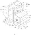
FIG. 1 is a perspective view illustrating an apparatus for preparing an aerogel blanket according to a first embodiment of the present invention. -
FIG. 2 is a front view ofFIG. 1 . -
FIG. 3 is a plan view ofFIG. 1 , -
FIG. 4 is a side view ofFIG. 1 . -
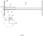
FIG. 5 is a front view illustrating a bobbin in the apparatus for preparing the aerogel blanket according to the first embodiment of the present invention. -
FIG. 6 is a side cross-sectional view ofFIG. 5 . -
FIG. 7 is a cross-sectional view illustrating a gelling tank in the apparatus for preparing the aerogel blanket according to the first embodiment of the present invention. -
FIG. 8 is a perspective view illustrating a state in which the bobbin and the rotation member are coupled to each other. -
FIG. 9 is a perspective view illustrating an aging member, a surface modifying member, and a drying member in the apparatus for preparing the aerogel blanket according to the first embodiment of the present invention. -
FIG. 10 is a flowchart illustrating a method for preparing an aerogel blanket according to the first embodiment of the present invention. -
FIG. 11 is a cross-sectional view illustrating an apparatus for preparing an aerogel blanket according to a second embodiment of the present invention. - Hereinafter, embodiments of the present invention will be described in detail with reference to the accompanying drawings in such a manner that the technical idea of the present invention may easily be carried out by a person with ordinary skill in the art to which the invention pertains. The present invention may, however, be embodied in different forms and should not be construed as limited to the embodiments set forth herein. In the drawings, anything unnecessary for describing the present invention will be omitted for clarity, and also like reference numerals in the drawings denote like elements.
- As illustrated in
FIGS. 1 to 9 , an apparatus for preparing an aerogel blanket according to a first embodiment of the present invention comprises abobbin 100 around which ablanket 10 is wound, amain body 200 provided with agelling tank 210 in which thebobbin 100 is accommodated, a drivingmember 300 configured to allow thebobbin 100 accommodated in thegelling tank 210 to rotate, a silicasol supply member 400 configured to gelate theblanket 10 as silica sol 20 is injected into thegelling tank 210 so as to be mixed into theblanket 10 that rotates by thebobbin 100, an agingmember 500 that ages theblanket 10, which rotates by thebobbin 100, by injecting an aging solution into thegelling tank 210, asurface modifying member 600 that modifies a surface of theblanket 10 by injecting a surface modifying solution into thegelling tank 210, and a dryingmember 700 in which thegelling tank 210 increases in temperature to dry theblanket 10 that rotates by thebobbin 100. - As illustrated in
FIGS. 5 and6 , thebobbin 100 is configured to wind the blanket in a roll shape and comprises a windingrod 110 around which theblanket 10 is wound in the roll shape and asupport plate 120 coupled to both ends of the windingrod 110 to support a side portion of theblanket 10 wound around the windingrod 110. - The winding
rod 110 has a cylindrical shape with a hollow 111 that is penetrated in a longitudinal direction, and theblanket 10 having a long sheet shape is wound around an outer surface of the windingrod 110. - The silica sol may be quickly impregnated into an outer portion of the
blanket 10 wound around the windingrod 110 to stably gelate theblanket 10. However, it is taken for a long time to impregnate an inner portion of theblanket 10 by using the silica sol. To prevent this problem, a plurality of connection holes 112 connected to the hollow 111 are defined in an outer circumferential surface of the windingrod 110. - That is, the hollow 111 may be defined in the winding
rod 110 so that the silica sol injected into thegelling tank 210 is introduced. The plurality of connection holes 112, through which the silica sol introduced into the hollow 111 is discharged out of the windingrod 110 is impregnated into the inner portion of theblanket 10 wound around the windingrod 110 so as to be impregnated into the inner portion of theblanket 10 wound around the windingrod 110, are defined in the windingrod 110. Thus, the inner portion and the outer portion of theblanket 10 may be gelated at the same time by impregnating the silica sol. Therefore, a time taken to gelate theblanket 10 may be significantly reduced to uniformly gelate theentire blanket 10. - Each of the plurality of connection holes 112 has a diameter of 3 mm to 5 mm, and the plurality of connection holes 112 are defined at regular intervals in the outer circumferential surface of the winding
rod 110. Thus, the silica sol may be uniformly supplied to theentire blanket 10 wound around the outer circumferential surface of the windingrod 110 to uniformly gelate the entire inside of theblanket 10. - The
support plate 120 is configured to support the blanket wound around the windingrod 110 so that the blanket is not irregularly wound. Thesupport plate 120 has a disc shape and is coupled to both ends of the windingrod 110 to support the side portion of theblanket 10 wound around the windingrod 110. - The
support plate 120 comprises acoupling groove 121, to which an end of the windingrod 110 is coupled, and acoupling hole 122 defined in a bottom surface of thecoupling groove 121. That is, thesupport plate 120 may be coupled to the end of the windingrod 110 through thecoupling groove 121. - A plurality of opening
holes 123 may be defined in thesupport plate 120. The silica sol may be introduced into the side portion of theblanket 10 wound around the windingrod 110 through the plurality of openingholes 123, and thus, the side portion of theblanket 10 may be stably gelated. - Therefore, the
bobbin 100 comprises the windingrod 110 and thesupport plate 120 to wind the blanket in the roll shape. - The
main body 200 is configured to install the gelling tank in which the bobbin is accommodated and comprises thegelling tank 210 and afirst installation member 220 on which thegelling tank 210 is installed. - The
gelling tank 210 is configured to gelate the blanket accommodated in the bobbin and comprises a gellingchamber 211 that is provided inside thegelling tank 210 to accommodate thebobbin 100, adischarge part 212 provided at an outer lower end of thegelling tank 210 and connected to the gellingchamber 211, and aninflow part 213 provided at an outer upper end of thegelling tank 210 and connected to the gellingchamber 211. - Particularly, the gelling
chamber 211 of thegelling tank 210 has a U-shaped cross-sectional shape of which an upper portion is opened by acover 214, and a lower portion has a curvature corresponding to thatblanket 10 wound around the windingrod 110. Thus, when the silica sol is introduced into the gellingchamber 211, contact force between the silica sol and theblanket 10 may increase to improve gelation of theblanket 10. - The
gelling tank 210 comprises arotation member 215 provided on both wall surfaces of the gellingchamber 211 and coupled to both ends of thebobbin 100 so that thebobbin 100 is rotatably installed in the gellingchamber 211. - The
rotation member 215 is rotatably installed in a through-hole defined in each of both the wall surfaces of the gelling chamber so that the end of thebobbin 100 accommodated in the gellingchamber 211 is capable of transmitting power. - For example, as illustrated in
FIG. 8 , acoupling protrusion 215a having a straight-line shape is disposed on one surface of therotation member 215, and acoupling groove 124 having a straight-line shape and coupled to thecoupling protrusion 215a is defined in the end of thebobbin 100. That is, when therotation member 215 rotates thebobbin 100 may rotate in the same direction through the coupling of thecoupling protrusion 215a and thecoupling groove 124. As a result, thebobbin 100 may be rotatably installed inside thegelling tank 210. - The
main body 200 further comprises asecond installation member 230 on which the silicasol supply member 400 is installed. Thesecond installation member 230 comprises abottom piece 231, aninstallation frame 232 installed on an upper portion of thebottom piece 231 and installed so that the silicasol supply member 400 is disposed higher than that gellingtank 210, and astair 233 installed on an end of one side of thebottom piece 231. - The gelling tank comprises a
rotation handle 216 coupled to the other rotation member 215 (the left rotation member when viewed inFIG. 1 ) provided in the gelling tank to allow the bobbin to rotate. The rotation handle 216 may allow thebobbin 100 to manually rotate at the outside. - Referring to
FIG. 9 , the agingmember 500, thesurface modifying member 600, and the dryingmember 700 are further installed on theinstallation frame 232 of thesecond installation member 230. - The driving
member 300 is configured to allow the bobbin accommodated in the gelling tank to rotate. The drivingmember 300 is connected to the other rotation member 215 (the right rotation member when viewed inFIG. 1 ) provided in thegelling tank 210 to transmit power. That is, when therotation member 215 rotates, the drivingmember 300 may be interlocked with therotation member 215 to allow thebobbin 100 accommodated in thegelling tank 210 to rotate. - The silica
sol supply member 400 is configured to gelate the blanket by injecting the silica sol into the gelling tank to impregnate the blanket wound around the bobbin. The silicasol supply member 400 is installed on theinstallation frame 232 to supply the silica sol into the gellingchamber 211 through theinflow part 213 of thegelling tank 210. - The aging
member 500 is configured to age the blanket wound around the bobbin. The agingmember 500 is installed on theinstallation frame 232 to supply an aging solution into the gellingchamber 211 through theinflow part 213 of thegelling tank 210. - The
surface modifying member 600 is configured to inject a surface modifying solution into the gelling tank so as to modify the surface of the blanket. Thesurface modifying member 600 is installed on theinstallation frame 232 to supply the surface modifying solution into thegelling tank 210 through theinflow part 213. - The drying
member 700 is configured to supply high-temperature hot air into the gelling tank so as to dry the blanket wound around the bobbin. The dryingmember 700 is installed on theinstallation frame 232 and rises a temperature of thegelling tank 210 to dry theblanket 10 accommodated in thegelling tank 210. - Thus, in the apparatus for preparing the aerogel blanket according to the first embodiment of the present invention, the time taken to prepare the aerogel blanket may be significantly reduced, and the productivity of the aerogel blanket may be significantly improved to mass-produce the aerogel blanket.
- Particularly, the apparatus for preparing the aerogel blanket according to the first embodiment of the present invention may induce the stable gelation regardless of a thickness and length of the blanket as the blanket rotates. Since the bobbin rotates, the entire blanket wound around the bobbin may be uniformly gelated. Also, since only the bobbin rotates without the gelling tank does not rotate, the gelling tank is not limited in shape. Also, since the gelling chamber of the gelling tank has the 'U'-shaped cross-sectional shape, the blanket wound around the bobbin may be more effectively gelated.
- Hereinafter, a method of preparing the aerogel blanket according to the first embodiment of the present invention will be described.
- As illustrated in
FIGS. 1 ,9 , and10 , a method for preparing the aerogel blanket according to the first embodiment of the present invention comprises a winding step (S10) of winding a blanket 10 around a bobbin 100, an accommodation step (S20) in which the bobbin 100 around which the blanket 10 is wound is rotatably installed inside a gelling tank 210 of a main body 200, a silica sol preparation step (S30) of injecting a precursor solution and a catalyst solution into a silica sol supply member 300 to mix the precursor solution and the catalyst solution with each other, thereby preparing silica sol, a rotation step (S40) of allowing the bobbin 100, around which the blanket 10 is wound, to rotate through a driving member 400, a gelation step (S50) of injecting the silica sol mixed in the silica sol supply member into the gelling tank 210 to impregnate the silica sol into the blanket 10 rotating by the bobbin 100, thereby gelating the blanket 10, a collection step (S60) of collecting the silica sol remaining in the gelling tank 210, an aging step (S70) of injecting an aging solution into the gelling tank 210 through the aging member 500 to age the blanket 10 rotating by the bobbin 100, a surface modifying step (S80) of injecting a surface modifying solution into the gelling tank 210 through the surface modifying member 600 to modify a surface of the blanket 10 rotating by the bobbin 100, and a drying step (S90) of rising a temperature of the gelling tank 210 through a drying member 700 to dry the blanket 10 accommodated in the gelling tank 210, thereby completing the aerogel blanket. - In the winding step (S10), the
blanket 10 is wound in a roll shape by using thebobbin 100. That is, theblanket 10 is wound in the roll shape in a state of locating a start point of theblanket 10 at a windingrod 110 of thebobbin 100. Here, a side portion of theblanket 10 wound around the windingrod 110 may be wound uniformly as being supported by asupport plate 120. - Particularly, the blanket may be a porous base material in terms of improving heat insulating properties of the aerogel blanket. When the porous blanket is used, the catalyzed sol may be easily penetrated into the base material to uniformly form the aerogel in the blanket. Thus, the prepared aerogel blanket may have excellent thermal insulation properties.
- That is, the blanket may be a film, a sheet, a net, fiber, foam, nonwoven fabric, or a laminate having two or more layers thereof. Also, surface roughness may be formed or patterned on the surface of the blanket according to application of the blanket. More particularly, the blanket may comprise a space or pore, through which the aerogel is easily injected, to improve thermal insulation performance. It may be preferable that the blanket has low thermal conductivity.
- Particularly, the blanket may be polyamide, polybenzimidazole, polyaramid, an acrylic resin, a phenol resin, polyester, polyether ether ketone (PEEK), polyolefin (for example, polyethylene, polypropylene, or a copolymer thereof), cellulose, carbon, cotton, wool, hemp, non-woven fabric, glass fiber, or ceramic wool, and more specifically, the blanket may be glass fiber (glass felt).
- In the accommodation step (S20), the
bobbin 100 around which theblanket 10 is wound is rotatably installed inside thegelling tank 210 provided in theman body 200. That is, thebobbin 100 is accommodated in thegelling tank 210, and then, both ends of thebobbin 100 are installed on therotation members 215 provided on both wall surfaces of thegelling tank 210, respectively. Thus, thebobbin 100 may rotate by being interlocked with therotation member 215. That is, when therotation member 215 rotates, thebobbin 100 may be interlocked with therotation member 215 to rotate. Since thebobbin 100 rotates, theblanket 10 may also rotate. - In the silica sol preparation step (S30), the precursor solution and the catalyst solution are injected into the silica
sol supply member 300 and then mixed with each other to prepare catalyzed silica sol. - The catalyzed silica sol may be prepared by mixing sol with a base catalyst, and the base catalyst allows the sol to increase in pH, thereby promoting gelation.
- Here, the silica sol is not limited as long as the silica sol is a material capable of forming porous gel by a sol-gel reaction. Particularly, the silica sol may comprise inorganic sol, organic sol, or a combination thereof. The inorganic sol may comprise zirconia, yttrium oxide, hafnia, alumina, titania, ceria, silica, magnesium oxide, calcium oxide, magnesium fluoride, calcium fluoride and combinations thereof, and the organic sol may comprise polyacrylate, polyolefin, polystyrene, polyacrylonitrile, polyurethane, polyimide, polyfurfural alcohol, phenol furfuryl alcohol, melamine formaldehyde, resorcinol formaldehyde, cresol formaldehyde, phenol formaldehyde, polyvinyl alcohol dialdehyde, polysianurates, polyacrylamides, various epoxies, agar, agarose, and combinations thereof.
- The silica sol may be prepared by mixing a silica precursor material with alcohol. Also, the silica sol may undergo hydrolysis at a low pH to facilitate the gelation.
- Here, the precursor solution, which is the silica precursor usable for the preparation of the silica sol, may be a silicon-containing alkoxide-based compound, specifically, tetraalkyl silicate such as tetramethyl orthosilicate (TMOS), tetraethyl orthosilicate (TEOS), methyl triethyl orthosilicate, dimethyl diethyl orthosilicate, tetrapropyl orthosilicate, tetraisopropyl orthosilicate, tetrabutyl orthosilicate, tetra secondary butyl orthosilicate, tetra tertiary butyl orthosilicate, tetrahexyl orthosilicate, tetracyclohexyl orthosilicate, tetradodecyl orthosilicate, and the like. Among these, the silica precursor according to an embodiment of the present invention may be tetraethyl orthosilicate (TEOS).
- The precursor solution, which is the silica precursor, may be used in an amount so that a content of silica (SiO2) contained in the silica sol ranges of 3% wt% to 30% wt%. If the content of the silica is less than 3 wt%, a content of the silica aerogel in the finally prepared blanket is too low to cause a problem that a desired level of a thermal insulation effect is not expected. If the content of the silica exceeds 30 wt%, there is a fear that the silica aerogel is excessively formed to deteriorate mechanical properties of the blanket, particularly, flexibility of the blanket.
- Particularly, alcohol that is capable of being used for the preparation of the silica sol may comprise monohydric alcohol such as methanol, ethanol, isopropanol and butanol; polyhydric alcohol such as glycerol, ethylene glycol, propylene glycol, diethylene glycol, dipropylene glycol, and sorbitol, or a mixture of two or more of the above materials. Among these, when considering miscibility with water and aerogel, monohydric alcohol having 1 to 6 carbon atoms such as methanol, ethanol, isopropanol, butanol, and the like may be used.
- In the silica sol, the precursor solution, which is the silica precursor, and water are contained at a molar ratio of 1:4 to 1:1. Also, the silica precursor and the alcohol may be contained at a weight ratio of 1:2 to 1:9 and preferably may be contained at a weight ratio of 1:4 to 1:6. When the silica precursor solution satisfies the above weight ratio, an improvement effect in terms of the thermal insulation performance may be improved.
- The base catalysts usable in the catalyzed silica sol may be inorganic bases such as sodium hydroxide and potassium hydroxide; or organic bases such as ammonium hydroxide. Particularly, the base catalysts may be one or more selected from the group consisting of sodium hydroxide (NaOH), potassium hydroxide (KOH), calcium hydroxide (Ca(OH)2), ammonia (NH3), ammonium hydroxide (NH4OH), tetramethylammonium hydroxide (TMAH), tetraethylammonium hydroxide (TEAH), tetrapropylammonium hydroxide (TPAH), tetrabutylammonium hydroxide (TBAH), methylamine, ethylamine, isopropylamine, monoisopropylamine, diethylamine, diisopropylamine, dibutylamine, trimethylamine, triethylamine, triisopropylamine, tributylamine, choline, monoethanolamine, diethanolamine, 2-aminoethanol, 2-(ethyl amino)ethanol, 2-(methyl amino)ethanol, N-methyl diethanolamine, dimethylaminoethanol, diethylaminoethanol, nitrilotriethanol, 2-(2-aminoethoxy)ethanol, 1-amino-2-propanol, triethanolamine, monopropanolamine, dibutanolamine, preferably, may be sodium hydroxide, ammonia, ammonium hydroxide, or a mixture thereof.
- The base catalyst may be contained in an amount so that the sol has a pH of 7 to 11. When the pH of the silica sol is out of the above range, the gelation may not be easy, or a gelation rate may be too slow to deteriorate processability. Also, since the base is precipitated when being put into a solid phase, it may be preferable to be added in a solution phase that is diluted with the above-mentioned alcohol (a polar organic solvent). Here, a dilution ratio of the base catalyst and the alcohol may be 1:4 to 1:100 based on a volume.
- When the method for preparing the silica sol is described in more detail with reference to the above components, the precursor solution is prepared by mixing an alkoxide-based silica precursor with water and ethanol in the silica
sol supply member 300. Here, when the silica precursor is tetraethyl orthosilicate (TEOS), TEOS and ethanol are diluted to have a weight ratio of 1:5, and then, TEOS and water are mixed at a molar ratio of 1:4. Next, TEOS is hydrolyzed. Here, hydrochloric acid is added so that the silica precursor solution has a pH of 3 or less to promote the hydrolysis. Next, an opacifying agent and a flame retardant corresponding to a weight ratio of 0 to 1 of the precursor solution are put into the precursor solution and stirred for 30 minutes. Next, 0 to 10 vol% of an ammonia ethanol solution (base catalyst solution) is mixed with the precursor solution to prepare the silica sol. - In the rotation step (S40), the
rotation member 215 of thegelling tank 210 rotates through the drivingmember 300. Thus, thebobbin 100 accommodated in thegelling tank 210 may rotate through therotation member 215, and theblanket 10 wound around thebobbin 100 in the roll shape may rotate inside thegelling tank 210 by the rotation of thebobbin 100. Here, thebobbin 100 may stably rotate by tworotation members 215 provided in thegelling tank 210. - In the gelation step (S50), the silica sol mixed in the silica
sol supply member 300 is supplied through aninflow part 213 of thegelling tank 210. Thus, the silica sol supplied to thegelling tank 210 may be impregnated into theblanket 10 wound around thebobbin 100 to gelate theblanket 10. Particularly, since theblanket 10 wound around thebobbin 100 rotates, theentire blanket 10 may be uniformly gelated. - In the collection step (S60), when the gelation is completed, the silica sol remaining in the gelling
chamber 211 is discharged to the outside through thedischarge part 212 of thegelling tank 210 and then is collected. - In the aging step (S70), an aging
solution 500 of the agingmember 500 is injected through theinflow part 213 of thegelling tank 210 to age theblanket 10 rotating by thebobbin 100. That is, 1% to 10 vol% of ammonia and ethanol solution are injected to thegelling tank 210, and thegelling tank 210 is aged for 25 minutes to 100 minutes while the gelling tank is maintained at a temperature at 25°C to 80°C. When the aging of the blanket is completed, the aging solution remaining in the gellingchamber 211 is collected through thedischarge part 212 of thegelling tank 210. Here, theblanket 10 may be maintained in the rotating state due to thebobbin 100 to effectively age the surface of theblanket 10. - In the surface modifying step (S80), a surface modification solution of the
surface modifying member 600 is injected into thegelling tank 210 to modify the surface of theblanket 10 rotating by thebobbin 100. That is, to modify the surface of theblanket 10, the surface modification is performed for 1 hour to 24 hours at 1 vol% to 10 vol% of a hexamethyldisilazane (HMDS) ethanol diluted solution. When the surface modification of the blanket is completed, the surface modifying solution remaining in thegelling tank 210 is collected. Here, theblanket 10 may be maintained in the rotating state due to thebobbin 100 to more effectively modify the surface of theblanket 10. - In the drying step (S90), a temperature inside the
gelling tank 210 increases through the dryingmember 700 to dry theblanket 10 accommodated in thegelling tank 210, thereby completing the aerogel blanket. That is, CO2 is injected through theinflow part 213 of thegelling tank 210, a temperature of thegelling tank 210 increases to 60°C over 1 hour, and supercritical drying is performed at a temperature of 60°C and a pressure of 100 bar. Ambient drying is performed on theblanket 10 for 2 hours in a state in which thegelling tank 210, in which the supercritical drying is completed, increases to a temperature of 200°C to completely remove residual salt and moisture. Thus, a hydrophobic silica aerogel blanket may be prepared. - Here, since the
blanket 10 rotates by thebobbin 100, theentire blanket 10 may be uniformly dried. - Therefore, in the method for preparing the aerogel blanket according to the present invention, the silica sol in the blanket may be gelated, aged, surface-modified, and dried in the gelling tank to prepare a finished product aerogel blanket.
- Hereinafter, in describing another embodiment of the present invention, a constituent having the same function as that described in the foregoing embodiment will be denoted by the same reference symbol, and its duplicated description will be omitted.
- As illustrated in
FIG. 2 , an apparatus for preparing an aerogel blanket according to a second embodiment of the present invention comprises abobbin 100 around which ablanket 10 is wound, and thebobbin 100 comprises a windingrod 110 and asupport plate 120. - Here, a fixing
clip 113 into which a winding start point of theblanket 10 is fitted and fixed is provided on an outer circumferential surface of the windingrod 110. - That is, referring to
FIG. 11 , the fixingclip 113 has a pin shape having elastic restoring force and has one end fixed to the outer circumferential surface of the windingrod 110 and the other end that is elastically supported on an outer circumferential surface of the windingrod 110. Therefore, when the start point of theblanket 10 is inserted between the other end of the fixingclip 113 and the windingrod 110, the start point of the windingrod 110 may be fixed to theblanket 10 by the elastic force of the fixingclip 113. As a result, theblanket 10 may be easily wound around the outer circumferential surface of the windingrod 110. - Accordingly, the scope of the present invention is defined by the appended claims more than the foregoing description and the exemplary embodiments described therein. Various modifications made within the meaning of an equivalent of the claims of the invention and within the claims are to be regarded to be in the scope of the present invention.
Claims (15)
- An apparatus for preparing an aerogel blanket, the apparatus comprising:a bobbin around which a blanket is wound;a main body provided with a gelling tank in which the bobbin is accommodated;a driving member configured to allow the bobbin accommodated in the gelling tank to rotate; anda silica sol supply member configured to gelate the blanket as silica sol is injected into the gelling tank to impregnate the blanket rotating by the bobbin.
- The apparatus of claim 1, wherein the bobbin comprises a winding rod around which the blanket is wound in the roll shape and a support plate coupled to both ends of the winding rod to support a side portion of the blanket wound around the winding rod.
- The apparatus of claim 2, wherein the winding rod has an inner portion in which a hollow, into which the silica sol injected into the gelling tank is introduced, is defined and an outer portion in which a plurality of connection holes, through which the silica sol introduced into the hollow is discharged to the outside of the winding rod so as to be impregnated into the blanket wound around the winding rod, are defined.
- The apparatus of claim 2, wherein a plurality of opening holes are defined in the support plate.
- The apparatus of claim 1, wherein the gelling tank comprises a gelling chamber that is provided inside the gelling tank to accommodate the bobbin, a discharge part provided at an outer lower end of the gelling tank and connected to the gelling chamber, and an inflow part provided at an outer upper end of the gelling tank and connected to the gelling chamber, and
the gelling chamber has a U-shaped cross-sectional shape of which an upper portion is opened by a cover. - The apparatus of claim 5, wherein the gelling tank comprises a rotation member provided on both wall surfaces of the gelling chamber and coupled to both ends of the bobbin so that the bobbin is rotatably installed in the gelling chamber.
- The apparatus of claim 6, wherein a coupling groove is defined in each of both ends of the bobbin, and a coupling protrusion is disposed on the rotation member, and
the bobbin and the rotation member are interlocked with each other to rotate by coupling of the coupling groove and the coupling protrusion. - The apparatus of claim 6, wherein the driving member allows the bobbin to rotate through one rotation member provided in the gelling tank.
- The apparatus of claim 6, wherein the gelling tank comprises a rotation handle coupled to the other rotation member provided in the gelling tank to allow the bobbin to rotate.
- A method for preparing an aerogel blanket, the method comprising:a winding step (S10) of winding a blanket around a bobbin;an accommodation step (S20) in which the bobbin around which the blanket is wound is rotatably installed inside a gelling tank;a silica sol preparation step (S30) of injecting a precursor solution and a catalyst solution into a silica sol supply member to mix the precursor solution and the catalyst solution with each other, thereby preparing silica sol;a rotation step (S40) of allowing the bobbin, around which the blanket is wound, to rotate through a driving member; anda gelation step (S50) of injecting the silica sol mixed in the silica sol supply member into the gelling tank to impregnate the silica sol into the blanket rotating by the bobbin, thereby gelating the blanket.
- The method of claim 10, further comprising, after the gelation step (S50), a collection step (S60) of collecting the silica sol remaining in the gelling tank.
- The method of claim 11, further comprising, after the collection step (S60), an aging step (S70) of injecting an aging solution into the gelling tank to age the blanket rotating by the bobbin and to collect the aging solution remaining in the gelling tank when the aging of the blanket is completed.
- The method of claim 12, further comprising, after the aging step (S70), a surface modifying step (S80) of injecting a surface modifying solution into the gelling tank to modify a surface of the blanket rotating by the bobbin and to collect the surface modifying solution remaining in the gelling tank when the surface modification of the blanket is completed.
- The method of claim 13, further comprising, after the surface modifying step (S80), a drying step (S90) of drying the blanket to complete the aerogel blanket.
- The method of claim 10, wherein, in the accommodation step (S20), when the bobbin around which the blanket is wound is accommodated in the gelling chamber of the gelling tank, and both ends of the bobbin are coupled to a rotation member that is rotatably provided on both wall surfaces of the gelling chamber, the bobbin around which the blanket is wound is rotatably installed inside the gelling tank.
Applications Claiming Priority (2)
| Application Number | Priority Date | Filing Date | Title |
|---|---|---|---|
| KR20190109158 | 2019-09-03 | ||
| PCT/KR2020/007517 WO2021045356A1 (en) | 2019-09-03 | 2020-06-10 | Apparatus and method for manufacturing aerogel blanket |
Publications (3)
| Publication Number | Publication Date |
|---|---|
| EP3882214A1 true EP3882214A1 (en) | 2021-09-22 |
| EP3882214A4 EP3882214A4 (en) | 2022-01-26 |
| EP3882214B1 EP3882214B1 (en) | 2023-11-08 |
Family
ID=74853399
Family Applications (1)
| Application Number | Title | Priority Date | Filing Date |
|---|---|---|---|
| EP20860326.6A Active EP3882214B1 (en) | 2019-09-03 | 2020-06-10 | Apparatus and method for manufacturing aerogel blanket |
Country Status (6)
| Country | Link |
|---|---|
| US (1) | US12053753B2 (en) |
| EP (1) | EP3882214B1 (en) |
| JP (1) | JP7105367B2 (en) |
| KR (1) | KR102487009B1 (en) |
| CN (1) | CN113226677A (en) |
| WO (1) | WO2021045356A1 (en) |
Families Citing this family (2)
| Publication number | Priority date | Publication date | Assignee | Title |
|---|---|---|---|---|
| CN115893974B (en) * | 2021-08-20 | 2024-07-02 | 巩义市泛锐熠辉复合材料有限公司 | Apparatus for preparing aerogel blanket and method thereof |
| CN119141724B (en) * | 2024-11-18 | 2025-04-18 | 清冠纳米科技(江苏)有限公司 | A device for separating impurities from aerogel |
Family Cites Families (77)
| Publication number | Priority date | Publication date | Assignee | Title |
|---|---|---|---|---|
| US1131270A (en) * | 1914-01-07 | 1915-03-09 | Howard L Quick | Method of treating fabrics. |
| WO1993016125A1 (en) | 1992-02-18 | 1993-08-19 | Matsushita Electric Works, Ltd. | Process for producing hydrophobic aerogel |
| DE4430642A1 (en) | 1994-08-29 | 1996-03-07 | Hoechst Ag | Airgel and xerogel composites, processes for their production and their use |
| WO1997017308A1 (en) | 1995-11-09 | 1997-05-15 | Aspen Systems, Inc. | Flexible aerogel superinsulation and its manufacture |
| DE19648798C2 (en) | 1996-11-26 | 1998-11-19 | Hoechst Ag | Process for the production of organically modified aerogels by surface modification of the aqueous gel (without prior solvent exchange) and subsequent drying |
| ITNO990004A1 (en) | 1999-03-08 | 2000-09-08 | Gel Design And Engineering S R | SOL-GEL PROCESS FOR THE PRODUCTION OF CONTAINING AND ADERENTIAD ARTICLES AND AN INCOMPRESSABLE CYLINDRICAL INSERT AND MANUFACTURES SO OBTAINED. |
| JP3792438B2 (en) | 1999-06-23 | 2006-07-05 | 株式会社神戸製鋼所 | Airgel membrane manufacturing method and manufacturing apparatus |
| JP2001072408A (en) | 1999-08-30 | 2001-03-21 | Matsushita Electric Works Ltd | Silica aerogel and its production |
| PT2422950E (en) | 2003-06-24 | 2014-12-09 | Aspen Aerogels Inc | METHODS FOR PRODUCING GEL LEAVES |
| DE602005003198T2 (en) | 2005-03-09 | 2008-08-28 | Degussa Novara Technology S.P.A. | Process for the preparation of monoliths by a sol-gel method |
| KR100710887B1 (en) | 2006-04-21 | 2007-04-27 | 요업기술원 | Manufacturing method of airgel blanket |
| KR20070114668A (en) | 2006-05-29 | 2007-12-04 | 한국생산기술연구원 | Airgel modified with epoxy and its manufacturing method |
| KR100831877B1 (en) | 2007-02-27 | 2008-05-23 | 한국에너지기술연구원 | Method for preparing silica airgel monolith at atmospheric pressure |
| KR101079308B1 (en) | 2008-11-12 | 2011-11-04 | 한국세라믹기술원 | Method for manufacturing aerogel blanket |
| KR101047965B1 (en) | 2009-06-11 | 2011-07-12 | 한국에너지기술연구원 | Airgel mat, manufacturing method and apparatus thereof |
| CN101698583B (en) | 2009-11-13 | 2012-08-22 | 航天特种材料及工艺技术研究所 | Multi-element aerogel composite material and preparation method thereof |
| KR101193987B1 (en) | 2010-01-11 | 2012-10-24 | 한국과학기술연구원 | Method for Preparing High-insulation Aerogel-Impregnated Fiber |
| JP2011190136A (en) | 2010-03-12 | 2011-09-29 | Asahi Kagaku Kk | Apparatus for manufacturing aerogel sheet |
| KR101147494B1 (en) | 2010-05-14 | 2012-05-21 | 주식회사 화인텍 | Manufacturing method of hydrophobic silica aerogel and hydrophobic silica aerogel manufactured therefrom |
| KR101147495B1 (en) | 2010-05-17 | 2012-05-21 | 주식회사 화인텍 | Manufacturing method for hydrophobic silica aerogel composites |
| KR20120070948A (en) | 2010-12-22 | 2012-07-02 | 주식회사 화인텍 | Manufacturing method of hydropobic silica aerogel powder with insulating performance |
| KR101176137B1 (en) | 2012-04-03 | 2012-08-22 | 주식회사 동양 | Manufacturing system and method for insulating padding including the hydrophobic silica aerogel |
| CN103910516A (en) | 2012-12-31 | 2014-07-09 | 上海新安纳电子科技有限公司 | Method for recovering waste silica sol for reutilization |
| JP6283541B2 (en) | 2013-03-12 | 2018-02-21 | Ykk株式会社 | Dyeing machine |
| KR101498562B1 (en) | 2013-04-04 | 2015-03-04 | 주식회사 아담스컴퍼니 | Manufacturing method of silica aerogel powders |
| EP4234619A3 (en) | 2014-10-03 | 2023-12-06 | Aspen Aerogels, Inc. | Improved hydrophobic aerogel materials |
| KR20160101330A (en) | 2015-02-16 | 2016-08-25 | 알이엠텍 주식회사 | micro-powder impregnated non-woven fabric and the method for preparing the same |
| KR102023531B1 (en) | 2015-04-07 | 2019-09-24 | 주식회사 엘지화학 | Aerogel containing composition and thermal insulation blanket prepared by using the same |
| KR101748527B1 (en) | 2015-04-14 | 2017-06-19 | 주식회사 엘지화학 | Method for preparing silica aerogel-containing blanket and silica aerogel-containing blanket prepared by using the same |
| WO2017009858A1 (en) | 2015-07-15 | 2017-01-19 | International Advanced Research Centre For Powder Metallurgy And New Materials (Arci) | An improved process for producing silica aerogel thermal insulation product with increased efficiency. |
| JP6330974B2 (en) | 2015-07-15 | 2018-05-30 | 日立化成株式会社 | Airgel composite material |
| KR101752091B1 (en) | 2015-09-10 | 2017-06-28 | 주식회사 엘지화학 | Blanket comprising silica aerogel and method for preparing the same |
| KR101774140B1 (en) * | 2016-01-19 | 2017-09-01 | 주식회사 엘지화학 | Preparation method and apparatus of aerogel sheet |
| CN105664809A (en) | 2016-01-29 | 2016-06-15 | 卓达新材料科技集团有限公司 | Supercritical drying method of felt/silicon-aluminum aerogel composite insulation board |
| CN105597635A (en) | 2016-01-29 | 2016-05-25 | 卓达新材料科技集团有限公司 | Normal-pressure drying method of felt/silicon-aluminum aerogel composite heat-preservation board |
| KR101654795B1 (en) * | 2016-02-05 | 2016-09-06 | 김현철 | Method for Preparing High-insulation Aerogel - Impregnated Mat |
| KR101953347B1 (en) | 2016-02-16 | 2019-05-22 | 주식회사 엘지화학 | Preparation apparatus for aerogel sheet |
| KR101966358B1 (en) | 2016-02-16 | 2019-04-08 | 주식회사 엘지화학 | Preparation method and apparatus of aerogel sheet |
| KR101962207B1 (en) * | 2016-02-17 | 2019-03-27 | 주식회사 엘지화학 | Composite sheet preparation method and apparatus comprising aerogel sheet |
| KR101968648B1 (en) * | 2016-02-19 | 2019-04-12 | 주식회사 엘지화학 | Preparation method and apparatus of aerogel sheet |
| KR101962206B1 (en) | 2016-02-19 | 2019-03-27 | 주식회사 엘지화학 | Composite sheet preparation method and apparatus comprising aerogel sheet |
| KR101953349B1 (en) * | 2016-02-22 | 2019-02-28 | 주식회사 엘지화학 | Preparation apparatus for aerogel sheet |
| WO2017145359A1 (en) | 2016-02-26 | 2017-08-31 | ニチアス株式会社 | Composite, method for manufacturing same, and tubular body |
| WO2017171217A1 (en) | 2016-03-28 | 2017-10-05 | 주식회사 엘지화학 | Method for manufacturing low-dust high-insulation aerogel blanket |
| KR101955184B1 (en) | 2016-03-28 | 2019-03-08 | 주식회사 엘지화학 | Method of preparing for aerogel blanket with low dust and high thermal insulation |
| CN114181533A (en) | 2016-03-29 | 2022-03-15 | 昭和电工材料株式会社 | Method for producing aerogel composite powder |
| KR102113324B1 (en) | 2016-09-23 | 2020-05-20 | 주식회사 엘지화학 | Silica aerogel blanket for ultra-high temperature, method for preparing the same and method for constructing using the same |
| CN106630930B (en) | 2016-09-28 | 2019-01-25 | 泰州浩纳新材料科技有限公司 | A method of continuously preparing aeroge insulation felt |
| US20200025324A1 (en) | 2016-09-30 | 2020-01-23 | Hitachi Chemical Company, Ltd. | Process for producing aerogel composite, aerogel composite, and heat-insulated object |
| CN106830878B (en) | 2017-01-18 | 2018-04-06 | 加新科技(深圳)有限公司 | A kind of super-hydrophobicity sial zirconium composite material and preparation method thereof |
| CN108689678B (en) | 2017-04-10 | 2020-04-07 | 航天海鹰(镇江)特种材料有限公司 | Fiber-reinforced aerogel felt without aerogel large particles attached to surface and preparation method thereof |
| CN107129262A (en) | 2017-04-10 | 2017-09-05 | 航天海鹰(镇江)特种材料有限公司 | A kind of ultra-thin aerogel composite and preparation method thereof |
| CN107140938B (en) | 2017-04-25 | 2018-09-04 | 天津朗华科技发展有限公司 | A kind of anti-powdering airgel composite thermal insulation felt and preparation method thereof |
| KR102148388B1 (en) | 2017-05-12 | 2020-08-26 | 주식회사 엘지화학 | Febrication method of silica aerogel blanket and silica aerogel blanket fabricated by the same |
| CN107034678B (en) | 2017-05-15 | 2019-05-10 | 爱彼爱和新材料有限公司 | A kind of polyurethane and aerosil composite insulation material and preparation method |
| JP7119292B2 (en) | 2017-06-06 | 2022-08-17 | 昭和電工マテリアルズ株式会社 | Package containing airgel and method for manufacturing package containing airgel |
| KR102369331B1 (en) | 2017-07-14 | 2022-03-03 | 주식회사 엘지화학 | Method for preparing hydrophobic silica aerogel |
| CN207310663U (en) | 2017-08-17 | 2018-05-04 | 江苏泛亚微透科技股份有限公司 | A kind of aerosil heat insulation felt |
| KR102377622B1 (en) | 2017-08-24 | 2022-03-24 | 주식회사 엘지화학 | Method preparing for silica aerogel blanket and apparatus preparing for the same |
| CN107523275B (en) | 2017-08-25 | 2020-05-19 | 北京科技大学 | A kind of preparation method of flexible silica aerogel-based phase change composite material |
| KR102193438B1 (en) | 2017-11-16 | 2020-12-21 | 주식회사 엘지화학 | Silica aerogel blanket with low dust and method for preparing the same |
| KR101911188B1 (en) | 2017-11-28 | 2018-10-23 | 주식회사 엘지화학 | Composite insulation sheet including aerogel and method for preparing the same |
| KR102231590B1 (en) | 2017-11-30 | 2021-03-23 | (주)엘지하우시스 | Method of manufacturing aerogel blanket and aerogel and produced aerogel blanket |
| CN109868598B (en) | 2017-12-04 | 2021-11-19 | 航天建筑设计研究院有限公司 | Impregnation method |
| KR102037425B1 (en) | 2017-12-27 | 2019-10-28 | 에스케이씨 주식회사 | Method for preparing aerogel composites and apparatus therefor |
| CN108383129A (en) | 2018-01-30 | 2018-08-10 | 南京工业大学 | Preparation method of flexible hydrophobic silica aerogel |
| EP3674263B1 (en) | 2018-02-14 | 2023-04-05 | Lg Chem, Ltd. | Method for preparing hydrophobic silica aerogel granules |
| CN108585762A (en) | 2018-05-30 | 2018-09-28 | 巩义市泛锐熠辉复合材料有限公司 | The preparation method of heat-insulation and heat-preservation aerosil felt |
| CN108821741A (en) | 2018-07-27 | 2018-11-16 | 徐渊 | A kind of preparation method of aerogel blanket |
| US11866324B2 (en) | 2018-11-27 | 2024-01-09 | Lg Chem, Ltd. | Method for manufacturing aerogel blanket |
| JP7085647B2 (en) | 2018-12-13 | 2022-06-16 | エルジー・ケム・リミテッド | How to make an airgel blanket |
| CN109437832A (en) | 2018-12-18 | 2019-03-08 | 贵州航天乌江机电设备有限责任公司 | A kind of preparation method from hydrophobic type silicon dioxide silica aerogel composite material |
| WO2021045483A1 (en) | 2019-09-03 | 2021-03-11 | 주식회사 엘지화학 | Method for manufacturing aerogel blanket |
| KR102581268B1 (en) | 2019-09-03 | 2023-09-22 | 주식회사 엘지화학 | Method for preparing aerogel blanket |
| KR102701498B1 (en) | 2019-09-18 | 2024-09-03 | 주식회사 엘지화학 | Aerogel blanket and method preparing thereof |
| CN110615663B (en) | 2019-09-29 | 2022-04-26 | 北京林业大学 | Solid wood fiber/SiO2Aerogel composite thermal insulation material and preparation method thereof |
| CN111925186B (en) | 2020-07-11 | 2022-03-11 | 巩义市泛锐熠辉复合材料有限公司 | Preparation method of aluminum silicate fiber reinforced aerogel felt and impregnation reaction kettle |
-
2020
- 2020-06-10 EP EP20860326.6A patent/EP3882214B1/en active Active
- 2020-06-10 US US17/416,619 patent/US12053753B2/en active Active
- 2020-06-10 CN CN202080007437.1A patent/CN113226677A/en active Pending
- 2020-06-10 WO PCT/KR2020/007517 patent/WO2021045356A1/en not_active Ceased
- 2020-06-10 JP JP2021507638A patent/JP7105367B2/en active Active
- 2020-09-01 KR KR1020200111328A patent/KR102487009B1/en active Active
Also Published As
| Publication number | Publication date |
|---|---|
| JP7105367B2 (en) | 2022-07-22 |
| CN113226677A (en) | 2021-08-06 |
| US12053753B2 (en) | 2024-08-06 |
| WO2021045356A1 (en) | 2021-03-11 |
| EP3882214B1 (en) | 2023-11-08 |
| EP3882214A4 (en) | 2022-01-26 |
| JP2022503551A (en) | 2022-01-12 |
| US20220072734A1 (en) | 2022-03-10 |
| KR20210028127A (en) | 2021-03-11 |
| KR102487009B1 (en) | 2023-01-11 |
Similar Documents
| Publication | Publication Date | Title |
|---|---|---|
| US12090460B2 (en) | Method for producing aerogel blanket | |
| CN112119036A (en) | Manufacturing method of aerogel felt | |
| JP7317120B2 (en) | airgel blanket | |
| US12053753B2 (en) | Apparatus and method for preparing aerogel blanket | |
| US12139410B2 (en) | Aerogel blanket | |
| KR20200077262A (en) | Method for prepararing silica aerogel blanket | |
| KR20220053213A (en) | Method of preparing aerogel blanket | |
| KR102927977B1 (en) | Device and method of preparing for aerogel blanket | |
| KR102821651B1 (en) | Device and method of preparing for aerogel blanket |
Legal Events
| Date | Code | Title | Description |
|---|---|---|---|
| STAA | Information on the status of an ep patent application or granted ep patent |
Free format text: STATUS: THE INTERNATIONAL PUBLICATION HAS BEEN MADE |
|
| PUAI | Public reference made under article 153(3) epc to a published international application that has entered the european phase |
Free format text: ORIGINAL CODE: 0009012 |
|
| STAA | Information on the status of an ep patent application or granted ep patent |
Free format text: STATUS: REQUEST FOR EXAMINATION WAS MADE |
|
| 17P | Request for examination filed |
Effective date: 20210614 |
|
| AK | Designated contracting states |
Kind code of ref document: A1 Designated state(s): AL AT BE BG CH CY CZ DE DK EE ES FI FR GB GR HR HU IE IS IT LI LT LU LV MC MK MT NL NO PL PT RO RS SE SI SK SM TR |
|
| A4 | Supplementary search report drawn up and despatched |
Effective date: 20220104 |
|
| RIC1 | Information provided on ipc code assigned before grant |
Ipc: C01B 33/145 20060101ALI20211221BHEP Ipc: B01J 13/00 20060101ALI20211221BHEP Ipc: C01B 33/155 20060101ALI20211221BHEP Ipc: C01B 33/159 20060101ALI20211221BHEP Ipc: C01B 33/158 20060101AFI20211221BHEP |
|
| DAV | Request for validation of the european patent (deleted) | ||
| DAX | Request for extension of the european patent (deleted) | ||
| GRAP | Despatch of communication of intention to grant a patent |
Free format text: ORIGINAL CODE: EPIDOSNIGR1 |
|
| STAA | Information on the status of an ep patent application or granted ep patent |
Free format text: STATUS: GRANT OF PATENT IS INTENDED |
|
| INTG | Intention to grant announced |
Effective date: 20230831 |
|
| GRAS | Grant fee paid |
Free format text: ORIGINAL CODE: EPIDOSNIGR3 |
|
| GRAA | (expected) grant |
Free format text: ORIGINAL CODE: 0009210 |
|
| STAA | Information on the status of an ep patent application or granted ep patent |
Free format text: STATUS: THE PATENT HAS BEEN GRANTED |
|
| AK | Designated contracting states |
Kind code of ref document: B1 Designated state(s): AL AT BE BG CH CY CZ DE DK EE ES FI FR GB GR HR HU IE IS IT LI LT LU LV MC MK MT NL NO PL PT RO RS SE SI SK SM TR |
|
| REG | Reference to a national code |
Ref country code: GB Ref legal event code: FG4D |
|
| REG | Reference to a national code |
Ref country code: CH Ref legal event code: EP |
|
| REG | Reference to a national code |
Ref country code: DE Ref legal event code: R096 Ref document number: 602020020869 Country of ref document: DE |
|
| REG | Reference to a national code |
Ref country code: IE Ref legal event code: FG4D |
|
| REG | Reference to a national code |
Ref country code: LT Ref legal event code: MG9D |
|
| REG | Reference to a national code |
Ref country code: NL Ref legal event code: MP Effective date: 20231108 |
|
| PG25 | Lapsed in a contracting state [announced via postgrant information from national office to epo] |
Ref country code: GR Free format text: LAPSE BECAUSE OF FAILURE TO SUBMIT A TRANSLATION OF THE DESCRIPTION OR TO PAY THE FEE WITHIN THE PRESCRIBED TIME-LIMIT Effective date: 20240209 |
|
| PG25 | Lapsed in a contracting state [announced via postgrant information from national office to epo] |
Ref country code: IS Free format text: LAPSE BECAUSE OF FAILURE TO SUBMIT A TRANSLATION OF THE DESCRIPTION OR TO PAY THE FEE WITHIN THE PRESCRIBED TIME-LIMIT Effective date: 20240308 |
|
| PG25 | Lapsed in a contracting state [announced via postgrant information from national office to epo] |
Ref country code: LT Free format text: LAPSE BECAUSE OF FAILURE TO SUBMIT A TRANSLATION OF THE DESCRIPTION OR TO PAY THE FEE WITHIN THE PRESCRIBED TIME-LIMIT Effective date: 20231108 |
|
| REG | Reference to a national code |
Ref country code: AT Ref legal event code: MK05 Ref document number: 1629482 Country of ref document: AT Kind code of ref document: T Effective date: 20231108 |
|
| PG25 | Lapsed in a contracting state [announced via postgrant information from national office to epo] |
Ref country code: NL Free format text: LAPSE BECAUSE OF FAILURE TO SUBMIT A TRANSLATION OF THE DESCRIPTION OR TO PAY THE FEE WITHIN THE PRESCRIBED TIME-LIMIT Effective date: 20231108 |
|
| PG25 | Lapsed in a contracting state [announced via postgrant information from national office to epo] |
Ref country code: AT Free format text: LAPSE BECAUSE OF FAILURE TO SUBMIT A TRANSLATION OF THE DESCRIPTION OR TO PAY THE FEE WITHIN THE PRESCRIBED TIME-LIMIT Effective date: 20231108 |
|
| PG25 | Lapsed in a contracting state [announced via postgrant information from national office to epo] |
Ref country code: ES Free format text: LAPSE BECAUSE OF FAILURE TO SUBMIT A TRANSLATION OF THE DESCRIPTION OR TO PAY THE FEE WITHIN THE PRESCRIBED TIME-LIMIT Effective date: 20231108 |
|
| PG25 | Lapsed in a contracting state [announced via postgrant information from national office to epo] |
Ref country code: NL Free format text: LAPSE BECAUSE OF FAILURE TO SUBMIT A TRANSLATION OF THE DESCRIPTION OR TO PAY THE FEE WITHIN THE PRESCRIBED TIME-LIMIT Effective date: 20231108 Ref country code: LT Free format text: LAPSE BECAUSE OF FAILURE TO SUBMIT A TRANSLATION OF THE DESCRIPTION OR TO PAY THE FEE WITHIN THE PRESCRIBED TIME-LIMIT Effective date: 20231108 Ref country code: IS Free format text: LAPSE BECAUSE OF FAILURE TO SUBMIT A TRANSLATION OF THE DESCRIPTION OR TO PAY THE FEE WITHIN THE PRESCRIBED TIME-LIMIT Effective date: 20240308 Ref country code: GR Free format text: LAPSE BECAUSE OF FAILURE TO SUBMIT A TRANSLATION OF THE DESCRIPTION OR TO PAY THE FEE WITHIN THE PRESCRIBED TIME-LIMIT Effective date: 20240209 Ref country code: ES Free format text: LAPSE BECAUSE OF FAILURE TO SUBMIT A TRANSLATION OF THE DESCRIPTION OR TO PAY THE FEE WITHIN THE PRESCRIBED TIME-LIMIT Effective date: 20231108 Ref country code: BG Free format text: LAPSE BECAUSE OF FAILURE TO SUBMIT A TRANSLATION OF THE DESCRIPTION OR TO PAY THE FEE WITHIN THE PRESCRIBED TIME-LIMIT Effective date: 20240208 Ref country code: AT Free format text: LAPSE BECAUSE OF FAILURE TO SUBMIT A TRANSLATION OF THE DESCRIPTION OR TO PAY THE FEE WITHIN THE PRESCRIBED TIME-LIMIT Effective date: 20231108 Ref country code: PT Free format text: LAPSE BECAUSE OF FAILURE TO SUBMIT A TRANSLATION OF THE DESCRIPTION OR TO PAY THE FEE WITHIN THE PRESCRIBED TIME-LIMIT Effective date: 20240308 |
|
| PG25 | Lapsed in a contracting state [announced via postgrant information from national office to epo] |
Ref country code: SE Free format text: LAPSE BECAUSE OF FAILURE TO SUBMIT A TRANSLATION OF THE DESCRIPTION OR TO PAY THE FEE WITHIN THE PRESCRIBED TIME-LIMIT Effective date: 20231108 Ref country code: RS Free format text: LAPSE BECAUSE OF FAILURE TO SUBMIT A TRANSLATION OF THE DESCRIPTION OR TO PAY THE FEE WITHIN THE PRESCRIBED TIME-LIMIT Effective date: 20231108 Ref country code: PL Free format text: LAPSE BECAUSE OF FAILURE TO SUBMIT A TRANSLATION OF THE DESCRIPTION OR TO PAY THE FEE WITHIN THE PRESCRIBED TIME-LIMIT Effective date: 20231108 Ref country code: NO Free format text: LAPSE BECAUSE OF FAILURE TO SUBMIT A TRANSLATION OF THE DESCRIPTION OR TO PAY THE FEE WITHIN THE PRESCRIBED TIME-LIMIT Effective date: 20240208 Ref country code: LV Free format text: LAPSE BECAUSE OF FAILURE TO SUBMIT A TRANSLATION OF THE DESCRIPTION OR TO PAY THE FEE WITHIN THE PRESCRIBED TIME-LIMIT Effective date: 20231108 Ref country code: HR Free format text: LAPSE BECAUSE OF FAILURE TO SUBMIT A TRANSLATION OF THE DESCRIPTION OR TO PAY THE FEE WITHIN THE PRESCRIBED TIME-LIMIT Effective date: 20231108 |
|
| PG25 | Lapsed in a contracting state [announced via postgrant information from national office to epo] |
Ref country code: DK Free format text: LAPSE BECAUSE OF FAILURE TO SUBMIT A TRANSLATION OF THE DESCRIPTION OR TO PAY THE FEE WITHIN THE PRESCRIBED TIME-LIMIT Effective date: 20231108 |
|
| PG25 | Lapsed in a contracting state [announced via postgrant information from national office to epo] |
Ref country code: CZ Free format text: LAPSE BECAUSE OF FAILURE TO SUBMIT A TRANSLATION OF THE DESCRIPTION OR TO PAY THE FEE WITHIN THE PRESCRIBED TIME-LIMIT Effective date: 20231108 |
|
| PG25 | Lapsed in a contracting state [announced via postgrant information from national office to epo] |
Ref country code: SK Free format text: LAPSE BECAUSE OF FAILURE TO SUBMIT A TRANSLATION OF THE DESCRIPTION OR TO PAY THE FEE WITHIN THE PRESCRIBED TIME-LIMIT Effective date: 20231108 |
|
| PG25 | Lapsed in a contracting state [announced via postgrant information from national office to epo] |
Ref country code: SM Free format text: LAPSE BECAUSE OF FAILURE TO SUBMIT A TRANSLATION OF THE DESCRIPTION OR TO PAY THE FEE WITHIN THE PRESCRIBED TIME-LIMIT Effective date: 20231108 Ref country code: SK Free format text: LAPSE BECAUSE OF FAILURE TO SUBMIT A TRANSLATION OF THE DESCRIPTION OR TO PAY THE FEE WITHIN THE PRESCRIBED TIME-LIMIT Effective date: 20231108 Ref country code: RO Free format text: LAPSE BECAUSE OF FAILURE TO SUBMIT A TRANSLATION OF THE DESCRIPTION OR TO PAY THE FEE WITHIN THE PRESCRIBED TIME-LIMIT Effective date: 20231108 Ref country code: IT Free format text: LAPSE BECAUSE OF FAILURE TO SUBMIT A TRANSLATION OF THE DESCRIPTION OR TO PAY THE FEE WITHIN THE PRESCRIBED TIME-LIMIT Effective date: 20231108 Ref country code: EE Free format text: LAPSE BECAUSE OF FAILURE TO SUBMIT A TRANSLATION OF THE DESCRIPTION OR TO PAY THE FEE WITHIN THE PRESCRIBED TIME-LIMIT Effective date: 20231108 Ref country code: DK Free format text: LAPSE BECAUSE OF FAILURE TO SUBMIT A TRANSLATION OF THE DESCRIPTION OR TO PAY THE FEE WITHIN THE PRESCRIBED TIME-LIMIT Effective date: 20231108 Ref country code: CZ Free format text: LAPSE BECAUSE OF FAILURE TO SUBMIT A TRANSLATION OF THE DESCRIPTION OR TO PAY THE FEE WITHIN THE PRESCRIBED TIME-LIMIT Effective date: 20231108 |
|
| REG | Reference to a national code |
Ref country code: DE Ref legal event code: R097 Ref document number: 602020020869 Country of ref document: DE |
|
| PLBE | No opposition filed within time limit |
Free format text: ORIGINAL CODE: 0009261 |
|
| STAA | Information on the status of an ep patent application or granted ep patent |
Free format text: STATUS: NO OPPOSITION FILED WITHIN TIME LIMIT |
|
| 26N | No opposition filed |
Effective date: 20240809 |
|
| PG25 | Lapsed in a contracting state [announced via postgrant information from national office to epo] |
Ref country code: SI Free format text: LAPSE BECAUSE OF FAILURE TO SUBMIT A TRANSLATION OF THE DESCRIPTION OR TO PAY THE FEE WITHIN THE PRESCRIBED TIME-LIMIT Effective date: 20231108 |
|
| PG25 | Lapsed in a contracting state [announced via postgrant information from national office to epo] |
Ref country code: SI Free format text: LAPSE BECAUSE OF FAILURE TO SUBMIT A TRANSLATION OF THE DESCRIPTION OR TO PAY THE FEE WITHIN THE PRESCRIBED TIME-LIMIT Effective date: 20231108 |
|
| PG25 | Lapsed in a contracting state [announced via postgrant information from national office to epo] |
Ref country code: MC Free format text: LAPSE BECAUSE OF FAILURE TO SUBMIT A TRANSLATION OF THE DESCRIPTION OR TO PAY THE FEE WITHIN THE PRESCRIBED TIME-LIMIT Effective date: 20231108 |
|
| REG | Reference to a national code |
Ref country code: CH Ref legal event code: PL |
|
| PG25 | Lapsed in a contracting state [announced via postgrant information from national office to epo] |
Ref country code: LU Free format text: LAPSE BECAUSE OF NON-PAYMENT OF DUE FEES Effective date: 20240610 |
|
| PG25 | Lapsed in a contracting state [announced via postgrant information from national office to epo] |
Ref country code: IE Free format text: LAPSE BECAUSE OF NON-PAYMENT OF DUE FEES Effective date: 20240610 |
|
| PG25 | Lapsed in a contracting state [announced via postgrant information from national office to epo] |
Ref country code: BE Free format text: LAPSE BECAUSE OF NON-PAYMENT OF DUE FEES Effective date: 20240630 Ref country code: CH Free format text: LAPSE BECAUSE OF NON-PAYMENT OF DUE FEES Effective date: 20240630 |
|
| REG | Reference to a national code |
Ref country code: BE Ref legal event code: MM Effective date: 20240630 |
|
| PGFP | Annual fee paid to national office [announced via postgrant information from national office to epo] |
Ref country code: DE Payment date: 20250520 Year of fee payment: 6 |
|
| PGFP | Annual fee paid to national office [announced via postgrant information from national office to epo] |
Ref country code: GB Payment date: 20250520 Year of fee payment: 6 |
|
| PGFP | Annual fee paid to national office [announced via postgrant information from national office to epo] |
Ref country code: FR Payment date: 20250521 Year of fee payment: 6 |
|
| PG25 | Lapsed in a contracting state [announced via postgrant information from national office to epo] |
Ref country code: FI Free format text: LAPSE BECAUSE OF FAILURE TO SUBMIT A TRANSLATION OF THE DESCRIPTION OR TO PAY THE FEE WITHIN THE PRESCRIBED TIME-LIMIT Effective date: 20231108 |
|
| PG25 | Lapsed in a contracting state [announced via postgrant information from national office to epo] |
Ref country code: CY Free format text: LAPSE BECAUSE OF FAILURE TO SUBMIT A TRANSLATION OF THE DESCRIPTION OR TO PAY THE FEE WITHIN THE PRESCRIBED TIME-LIMIT; INVALID AB INITIO Effective date: 20200610 |
|
| PG25 | Lapsed in a contracting state [announced via postgrant information from national office to epo] |
Ref country code: HU Free format text: LAPSE BECAUSE OF FAILURE TO SUBMIT A TRANSLATION OF THE DESCRIPTION OR TO PAY THE FEE WITHIN THE PRESCRIBED TIME-LIMIT; INVALID AB INITIO Effective date: 20200610 |