EP3881880A1 - Assembly for a drug delivery device comprising a feedback feature - Google Patents
Assembly for a drug delivery device comprising a feedback feature Download PDFInfo
- Publication number
- EP3881880A1 EP3881880A1 EP21154046.3A EP21154046A EP3881880A1 EP 3881880 A1 EP3881880 A1 EP 3881880A1 EP 21154046 A EP21154046 A EP 21154046A EP 3881880 A1 EP3881880 A1 EP 3881880A1
- Authority
- EP
- European Patent Office
- Prior art keywords
- feedback
- feature
- actuator
- drug delivery
- feedback feature
- Prior art date
- Legal status (The legal status is an assumption and is not a legal conclusion. Google has not performed a legal analysis and makes no representation as to the accuracy of the status listed.)
- Pending
Links
Images


Classifications
-
- A—HUMAN NECESSITIES
- A61—MEDICAL OR VETERINARY SCIENCE; HYGIENE
- A61M—DEVICES FOR INTRODUCING MEDIA INTO, OR ONTO, THE BODY; DEVICES FOR TRANSDUCING BODY MEDIA OR FOR TAKING MEDIA FROM THE BODY; DEVICES FOR PRODUCING OR ENDING SLEEP OR STUPOR
- A61M5/00—Devices for bringing media into the body in a subcutaneous, intra-vascular or intramuscular way; Accessories therefor, e.g. filling or cleaning devices, arm-rests
- A61M5/178—Syringes
- A61M5/31—Details
- A61M5/315—Pistons; Piston-rods; Guiding, blocking or restricting the movement of the rod or piston; Appliances on the rod for facilitating dosing ; Dosing mechanisms
- A61M5/31565—Administration mechanisms, i.e. constructional features, modes of administering a dose
- A61M5/31566—Means improving security or handling thereof
- A61M5/3157—Means providing feedback signals when administration is completed
-
- A—HUMAN NECESSITIES
- A61—MEDICAL OR VETERINARY SCIENCE; HYGIENE
- A61M—DEVICES FOR INTRODUCING MEDIA INTO, OR ONTO, THE BODY; DEVICES FOR TRANSDUCING BODY MEDIA OR FOR TAKING MEDIA FROM THE BODY; DEVICES FOR PRODUCING OR ENDING SLEEP OR STUPOR
- A61M5/00—Devices for bringing media into the body in a subcutaneous, intra-vascular or intramuscular way; Accessories therefor, e.g. filling or cleaning devices, arm-rests
- A61M5/178—Syringes
- A61M5/31—Details
- A61M5/315—Pistons; Piston-rods; Guiding, blocking or restricting the movement of the rod or piston; Appliances on the rod for facilitating dosing ; Dosing mechanisms
- A61M5/31533—Dosing mechanisms, i.e. setting a dose
- A61M5/31545—Setting modes for dosing
- A61M5/31548—Mechanically operated dose setting member
- A61M5/3155—Mechanically operated dose setting member by rotational movement of dose setting member, e.g. during setting or filling of a syringe
-
- A—HUMAN NECESSITIES
- A61—MEDICAL OR VETERINARY SCIENCE; HYGIENE
- A61M—DEVICES FOR INTRODUCING MEDIA INTO, OR ONTO, THE BODY; DEVICES FOR TRANSDUCING BODY MEDIA OR FOR TAKING MEDIA FROM THE BODY; DEVICES FOR PRODUCING OR ENDING SLEEP OR STUPOR
- A61M2205/00—General characteristics of the apparatus
- A61M2205/58—Means for facilitating use, e.g. by people with impaired vision
- A61M2205/581—Means for facilitating use, e.g. by people with impaired vision by audible feedback
-
- A—HUMAN NECESSITIES
- A61—MEDICAL OR VETERINARY SCIENCE; HYGIENE
- A61M—DEVICES FOR INTRODUCING MEDIA INTO, OR ONTO, THE BODY; DEVICES FOR TRANSDUCING BODY MEDIA OR FOR TAKING MEDIA FROM THE BODY; DEVICES FOR PRODUCING OR ENDING SLEEP OR STUPOR
- A61M2205/00—General characteristics of the apparatus
- A61M2205/58—Means for facilitating use, e.g. by people with impaired vision
- A61M2205/582—Means for facilitating use, e.g. by people with impaired vision by tactile feedback
Definitions
- the present disclosure relates to an assembly for a drug delivery device.
- the assembly comprises a feedback feature.
- An assembly for a drug delivery device comprising a feedback feature.
- the feedback feature is configured to indicate an end of a dispense operation to a user by giving an audible and/or tactile feedback.
- the audible feedback may be, for example, an audible click.
- the tactile feedback may be, for example, an impact on the skin of a user, in particular on a user's finger.
- the tactile feedback may be a vibration of a part of the assembly.
- the feedback may be a well-defined signal.
- the feedback may indicate to a user that the actuator may be released and the device may be withdrawn from a user's skin.
- a feedback feature being configured to indicate the end of a dispense operation is that a clear indication is given to a user when a dispense operation has been completed.
- the use of the drug delivery device may be simplified for a user.
- the dosing accuracy of a drug delivery device may be increased.
- it may be inhibited that a user interrupts a dispense operation for example by withdrawing the drug delivery device from the skin, before a complete dose has been delivered.
- a feedback provides an additional benefit for visually impaired users.
- the assembly comprises an actuator, which is configured to be operated by a user in order to dispense a dose.
- a feedback feature may create a feedback when the actuator reaches an end position at the end of a dispense operation.
- the end position of the actuator may be a most distal position of the actuator.
- the term "most distal position" may describe a position of a part of the assembly which is closest to a dispensing end of the drug delivery device.
- the actuator may be in its end position when it is fully depressed into the drug delivery device.
- the actuator may be configured as a button.
- the feedback feature may be an integral part of the actuator.
- the assembly comprises a member which is configured to interact with the feedback feature.
- the member is configured to axially move when it does not interact with the feedback feature.
- the member is configured to axially move during an initial phase of a dispense operation.
- the interaction of the axially moveable member with the feedback feature may cause a feedback.
- the member may be a driver.
- the driver may be a part of the assembly which is configured to drive a piston rod in order to dispense a dose of medication.
- the driver may be engaged with the piston rod.
- the driver may be moved towards a distal end of the device due to a movement of the actuator.
- the member may be an indicator, for example a number sleeve.
- the member may be a separate member, for example a sleeve member.
- the member may axially move with respect to a housing of the drug delivery device between two stops at least during the setting of a dose.
- the member may be temporarily restrained between these two stops. Thereby, the member may be temporarily axially fixed.
- the member may be axially fixed when it interacts with the feedback feature, i. e. when the actuator contacts the feedback feature.
- the feedback feature is configured to snap through when it is compressed above a certain load.
- a feedback may be given to a user.
- the feedback feature is configured to snap through at the end of a dispense operation.
- the feedback feature is configured to snap through when the actuator reaches its end position. Initially during compression of the feedback feature, the stiffness of the feedback feature may remain fairly constant. At a certain point, the stiffness of the feedback feature may reduce significantly. Thereby, the force required to cause a further deflection of the feedback feature may decrease. This may cause the snap-through behaviour of the feedback feature.
- the feedback feature may be configured to be compressed between two parts of the assembly.
- the feedback feature may be compressed between the actuator and the axially moveable member.
- the feedback feature could be compressed between the housing and the driver.
- the feedback feature may comprise the shape of a dome.
- the feedback feature may be configured as a snap dome.
- the feedback feature may comprise the shape of an arched disk.
- the feedback feature comprises at least one recess.
- the recess may be, for example, a concave cut out. Due to the at least one recess, the feedback feature may comprise a sufficient flexibility. Thereby, the feedback feature may be configured to snap through when it is compressed above a certain load. In particular, the size and shape of the recess may influence the force which is necessary to cause the feedback feature to snap through.
- the actuator interacts with the feedback feature.
- the actuator may interact with the feedback feature during a dispense operation.
- the feedback feature may be arranged between the actuator and another part of the drug delivery device. When the actuator approaches its end position during a dispense operation, the feedback feature may be clamped between the actuator and the other part. When the actuator is further moved towards the other part, the feedback feature may be compressed by the actuator. In particular, the force on the feedback feature increases when the actuator is further moved towards the other part. In particular, the actuator may exert a force on the feedback feature during a dispense operation.
- the feedback feature may be an integral part of the other part.
- the feedback feature comprises a metal material.
- the feedback feature may comprise a plastic material.
- the feedback feature comprises a resilient material.
- the feedback feature comprises an opening, wherein at least one element of the assembly extends through the opening.
- the actuator may extend through the opening of the feedback feature.
- the driver may extend through the opening of the feedback feature.
- the feedback feature comprises a first feedback element and a second feedback element.
- the first feedback element may be configured to interact with the second feedback element.
- the first feedback element and the second feedback element may abut each other, in particular when the actuator approaches its end position.
- the second feedback element may exert a force on the first feedback element during the dispensing of a dose.
- the first feedback element may be deflected by the second feedback element during a dispense operation.
- the first feedback element may be, for example, a resilient element.
- the second feedback element may be, for example, a rigid element.
- the second feedback element may be a protrusion in a part of the assembly. In particular, the second feedback element may extend along the whole circumference of the part.
- the second feedback element may be a protrusion which extends along an inner circumference of a body part of the assembly.
- an audible feedback may be created.
- the first feedback element may be an integral part of a part of the device.
- the first feedback element may be an integral part of the actuator.
- the first feedback element may be an integral part of the indicator.
- the feedback feature comprises at least one resilient arm.
- the first feedback element may comprise at least one resilient arm.
- the feedback feature comprises two or more resilient arms.
- the at least one resilient arm extends in a proximal direction.
- the proximal direction may be a direction away from the dispensing end of the device.
- the at least one resilient arm extends in a distal direction.
- the at least one resilient arm may stick out from an element of the assembly in a radial direction.
- the at least one resilient arm may be deflected, in particular in a radial direction.
- the at least one resilient arm is integrally formed with a part of the assembly.
- the at least one arm is attached to, in particular integrally moulded with an injection moulded part of the device.
- the assembly comprises a rotation member which is configured to rotate during dispensing of a dose.
- the first feedback element of the feedback feature may be located at the rotation member.
- the rotation member may be, for example, an indicator, in particular a number sleeve.
- the feedback feature may be a resilient arm which is attached to the rotation member.
- the feedback element may extend along a circumferential direction of the rotation member.
- the feedback feature is configured to be deflected in a radial inward direction.
- the feedback feature is configured to give a feedback to a user during the dispensing of a dose.
- the feedback may indicate that the dispensing is ongoing.
- a first feedback element may permanently interact with a second feedback element during a dispense operation. At the end of a dispense operation, the feedback may be increased.
- the assembly comprises an enhancement feature.
- the enhancement feature may be configured to enhance a feedback signal.
- the enhancement feature may be, for example, a protrusion in one part of the assembly.
- the first feedback element is configured to interact with the enhancement feature at the end of the dispense operation.
- the first feedback element does not interact with the enhancement feature prior to the end of the dispense operation.
- the enhancement feature may be configured to reinforce the interaction of the first feedback element with the second feedback element.
- the second feedback element may comprise a plurality of protrusions or splines.
- the enhancement feature may increase the stiffness of the first feedback element.
- the enhancement feature may be in contact with the first feedback element at the end of a dispense operation.
- the enhancement feature may be in contact with a surface of the first feedback element which is faced towards a longitudinal axis of the device.
- the enhancement feature may limit a deflection of the first feedback element, in particular in a radially inward direction.
- the second feedback element is configured as a thread.
- the second feedback element may comprise a thread in a body part of the assembly.
- the first feedback element may be a resilient arm, which is for example located at the rotation member and may extend along a circumference direction of the rotation member.
- the first feedback element may interact with the thread of the second feedback element.
- the first feedback element may be preloaded due to the interaction with the thread of the second feedback element.
- the first feedback element may be strained in an axial or radial direction.
- the second feedback element may further comprise a step. The step may be located at a distal end of the thread. The step may extend in an axial or radial direction.
- the first feedback element When the first feedback element reaches the step at the end of a dispense operation, the first feedback element may, due to its preload, drop of the step. Thereby, the first feedback element may hit the wall of the body part. Thereby, an audible feedback may be created.
- a drug delivery device comprising an assembly which is configured as previously described.
- the drug delivery device may comprise a feedback feature, which is configured to indicate an end of a dispense operation to a user by giving an audible and/or tactile feedback.
- the drug delivery device may be an injection device.
- the drug delivery device may be a pen-type device.
- the drug delivery device may be a variable dose device such that a user can select the size of a dose.
- the drug delivery device may be configured for multiple dose applications.
- the medication may be delivered to a user by means of a needle.
- the device may be delivered to a user in a fully assembled condition ready for use.
- the drug delivery device may be a disposable device.
- the term "disposable" means that the drug delivery device cannot be reused after an available amount of medication has been delivered from the drug delivery device.
- the drug delivery device may be configured to deliver a liquid medication.
- the medication may be, for example, insulin.
- medication preferably means a pharmaceutical formulation containing at least one pharmaceutically active compound, wherein in one embodiment the pharmaceutically active compound has a molecular weight up to 1500 Da and/or is a peptide, a proteine, a polysaccharide, a vaccine, a DNA, a RNA, an enzyme, an antibody or a fragment thereof, a hormone or an oligonucleotide, or a mixture of the above-mentioned pharmaceutically active compound, wherein in a further embodiment the pharmaceutically active compound is useful for the treatment and/or prophylaxis of diabetes mellitus or complications associated with diabetes mellitus such as diabetic retinopathy, thromboembolism disorders such as deep vein or pulmonary thromboembolism, acute coronary syndrome (ACS), angina, myocardial infarction, cancer, macular degeneration, inflammation, hay fever, atherosclerosis and/or rheumatoid arthritis, wherein in a further embodiment the pharmaceutically
- Insulin analogues are for example Gly(A21), Arg(B31), Arg(B32) human insulin; Lys(B3), Glu(B29) human insulin; Lys(B28), Pro(B29) human insulin; Asp(B28) human insulin; human insulin, wherein proline in position B28 is replaced by Asp, Lys, Leu, Val or Ala and wherein in position B29 Lys may be replaced by Pro; Ala(B26) human insulin; Des(B28-B30) human insulin; Des(B27) human insulin and Des(B30) human insulin.
- Insulin derivates are for example B29-N-myristoyl-des(B30) human insulin; B29-N-palmitoyl-des(B30) human insulin; B29-N-myristoyl human insulin; B29-N-palmitoyl human insulin; B28-N-myristoyl LysB28ProB29 human insulin; B28-N-palmitoyl-LysB28ProB29 human insulin; B30-N-myristoyl-ThrB29LysB30 human insulin; B30-N-palmitoyl- ThrB29LysB30 human insulin; B29-N-(N-palmitoyl-Y-glutamyl)-des(B30) human insulin; B29-N-(N-lithocholyl-Y-glutamyl)-des(B30) human insulin; B29-N-( ⁇ -carboxyheptadecanoyl)-des(B30) human insulin and B29-N-( ⁇ -carbox
- Exendin-4 for example means Exendin-4(1-39), a peptide of the sequence H-His-Gly-Glu-Gly-Thr-Phe-Thr-Ser-Asp-Leu-Ser-Lys-Gln-Met-Glu-Glu-Glu-Ala-Val-Arg-Leu-Phe-Ile-Glu-Trp-Leu-Lys-Asn-Gly-Gly-Pro-Ser-Ser-Gly-Ala-Pro-Pro-Pro-Ser-NH2.
- Exendin-4 derivatives are for example selected from the following list of compounds:
- Hormones are for example hypophysis hormones or hypothalamus hormones or regulatory active peptides and their antagonists as listed in Rote Liste, ed. 2008, Chapter 50 , such as Gonadotropine (Follitropin, Lutropin, Choriongonadotropin, Menotropin), Somatropine (Somatropin), Desmopressin, Terlipressin, Gonadorelin, Triptorelin, Leuprorelin, Buserelin, Nafarelin, Goserelin.
- Gonadotropine Follitropin, Lutropin, Choriongonadotropin, Menotropin
- Somatropine Somatropin
- Desmopressin Terlipressin
- Gonadorelin Triptorelin
- Leuprorelin Buserelin
- Nafarelin Goserelin.
- a polysaccharide is for example a glucosaminoglycane, a hyaluronic acid, a heparin, a low molecular weight heparin or an ultra low molecular weight heparin or a derivative thereof, or a sulphated, e.g. a poly-sulphated form of the above-mentioned polysaccharides, and/or a pharmaceutically acceptable salt thereof.
- An example of a pharmaceutically acceptable salt of a poly-sulphated low molecular weight heparin is enoxaparin sodium.
- Antibodies are globular plasma proteins ( ⁇ 150 kDa) that are also known as immunoglobulins which share a basic structure. As they have sugar chains added to amino acid residues, they are glycoproteins.
- the basic functional unit of each antibody is an immunoglobulin (Ig) monomer (containing only one Ig unit); secreted antibodies can also be dimeric with two Ig units as with IgA, tetrameric with four Ig units like teleost fish IgM, or pentameric with five Ig units, like mammalian IgM.
- Ig immunoglobulin
- the Ig monomer is a "Y"-shaped molecule that consists of four polypeptide chains; two identical heavy chains and two identical light chains connected by disulfide bonds between cysteine residues. Each heavy chain is about 440 amino acids long; each light chain is about 220 amino acids long. Heavy and light chains each contain intrachain disulfide bonds which stabilize their folding. Each chain is composed of structural domains called Ig domains. These domains contain about 70-110 amino acids and are classified into different categories (for example, variable or V, and constant or C) according to their size and function. They have a characteristic immunoglobulin fold in which two ⁇ sheets create a "sandwich" shape, held together by interactions between conserved cysteines and other charged amino acids.
- Ig heavy chain There are five types of mammalian Ig heavy chain denoted by ⁇ , ⁇ , ⁇ , ⁇ , and ⁇ .
- the type of heavy chain present defines the isotype of antibody; these chains are found in IgA, IgD, IgE, IgG, and IgM antibodies, respectively.
- Distinct heavy chains differ in size and composition; ⁇ and ⁇ contain approximately 450 amino acids and ⁇ approximately 500 amino acids, while ⁇ and ⁇ have approximately 550 amino acids.
- Each heavy chain has two regions, the constant region (C H ) and the variable region (V H ).
- the constant region is essentially identical in all antibodies of the same isotype, but differs in antibodies of different isotypes.
- Heavy chains ⁇ , ⁇ and ⁇ have a constant region composed of three tandem Ig domains, and a hinge region for added flexibility; heavy chains ⁇ and ⁇ have a constant region composed of four immunoglobulin domains.
- the variable region of the heavy chain differs in antibodies produced by different B cells, but is the same for all antibodies produced by a single B cell or B cell clone.
- the variable region of each heavy chain is approximately 110 amino acids long and is composed of a single Ig domain.
- a light chain has two successive domains: one constant domain (CL) and one variable domain (VL).
- CL constant domain
- VL variable domain
- the approximate length of a light chain is 211 to 217 amino acids.
- Each antibody contains two light chains that are always identical; only one type of light chain, ⁇ or ⁇ , is present per antibody in mammals.
- variable (V) regions are responsible for binding to the antigen, i.e. for its antigen specificity.
- VL variable light
- VH variable heavy chain
- CDRs Complementarity Determining Regions
- an "antibody fragment” contains at least one antigen binding fragment as defined above, and exhibits essentially the same function and specificity as the complete antibody of which the fragment is derived from.
- Limited proteolytic digestion with papain cleaves the Ig prototype into three fragments. Two identical amino terminal fragments, each containing one entire L chain and about half an H chain, are the antigen binding fragments (Fab).
- the Fc contains carbohydrates, complement-binding, and FcR-binding sites.
- F(ab')2 is divalent for antigen binding.
- the disulfide bond of F(ab')2 may be cleaved in order to obtain Fab'.
- the variable regions of the heavy and light chains can be fused together to form a single chain variable fragment (scFv).
- Pharmaceutically acceptable salts are for example acid addition salts and basic salts.
- Acid addition salts are e.g. HCI or HBr salts.
- Basic salts are e.g. salts having a cation selected from alkali or alkaline, e.g. Na+, or K+, or Ca2+, or an ammonium ion N+(R1)(R2)(R3)(R4), wherein R1 to R4 independently of each other mean: hydrogen, an optionally substituted C1-C6-alkyl group, an optionally substituted C2-C6-alkenyl group, an optionally substituted C6-C10-aryl group, or an optionally substituted C6-C10-heteroaryl group.
- solvates are for example hydrates.
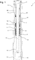
- Figure 1 shows a drug delivery device 1.
- the drug delivery device 1 is an injection device.
- the drug delivery device 1 is a variable dose device such that a user can select the size of a dose.
- the drug delivery device 1 is configured for multiple dose applications.
- the device can be delivered to a user in a fully assembled condition ready for use.
- the device has a low part count and is particularly attractive for cost-sensitive device applications.
- the drug delivery device 1 comprises a housing 3, an inner body 4, an actuator 5, an indicator 6, a driver 7, a piston rod 9, a piston 10, a last dose stop 11, and a cartridge 13.
- a needle arrangement comprising a needle hub and a needle cover may be provided as additional components.
- the housing 3 is a generally tubular element. A distal part of the housing 3 forms a cartridge holder 14 for receiving the cartridge 13.
- the inner body 4 is a generally tubular element.
- the inner body 4 is received in the housing 3 and is permanently fixed therein to prevent any relative movement of the inner body 4 with respect to the housing 3.
- An external thread 15 is provided on the outer surface of the inner body 4. At its distal end, the inner body 4 comprises a further thread 16.
- the actuator 5 is configured as a button.
- the actuator 5 is rotationally and axially moveable with respect to the housing 3 and the inner body 4.
- the actuator 5 is arranged at a proximal end of the drug delivery device 1.
- the actuator 5 is configured to be operated in order to dispense a dose of medication.
- the indicator 6 is a generally tubular element.
- the indicator 6 is configured as a rotation member 43.
- the indicator 6 is configured to rotate with respect to the housing 3 during the setting and the dispensing of a dose.
- the indicator 6 is arranged concentrically around the inner body 4.
- the indicator 6 comprises an internal thread 19 engaging with the external thread 15 of the inner body 4.
- the indicator 6 is arranged between the inner body 4 and the housing 3.
- a series of numbers is provided, e.g. printed, on the outer surface of the indicator 6.
- the numbers are arranged on a helical line such that only one number or only a few numbers are visible through a window 12 of the housing 3.
- the numbers indicate the amount of a set dose.
- the indicator 6 may have returned in its initial position, thereby indicating the end of a dispense operation to a user.
- the piston rod 9 is configured as a lead screw.
- the piston rod 9 comprises two counter-handed threads which overlap each other. One of the threads of the piston rod 9 engages with the inner thread 16 of the inner body 4.
- the driver 7 is a generally tubular element. An inner surface of the driver 7 has an inner thread 18 engaging with one of the external threads of the piston rod 9. The driver 7 is at least partly located within the inner body 4. A distal region of the driver 7 has an external thread 17. The driver 7 is configured to rotate and axially move with respect to the housing 3 during the setting of a dose. During the dispensing of a dose, the driver 7 is axially moveable and rotationally fixed with respect to the housing 3.
- the last dose stop 11 is provided between the inner body 4 and the driver 7. An internal thread of the last dose stop 11 engages with the external thread 17 of the driver 7.
- the last dose stop 11 is configured to inhibit the setting of a dose which is larger than an amount of medication remaining in the cartridge 13. This is achieved by the last dose stop 11 abutting an abutment feature of the driver 7 when a dose is set which corresponds to an amount of medication remaining in the cartridge 13.
- the last dose stop 11 is configured as a nut.
- the actuator 5 In order to set a dose, the actuator 5 is rotated by a user. During the setting of a dose, the indicator 6 and the driver 7 are rotationally fixed with respect to the actuator 5. Thereby, the actuator 5, the indicator 6 and the driver 7 are rotated out of the housing 3. Thereby, the driver 7 is rotated along the piston rod 9 in a proximal direction, while the piston rod 9 is axially and rotationally fixed with respect to the housing 3 during the setting of a dose. The indicator 6 is rotated along the thread 15 of the inner body 4.
- the actuator 5 In order to dispense a dose, the actuator 5 is operated by a user. In particular, the actuator 5 is pushed in a direction towards a dispensing end of the device. During the dispensing of a dose, the actuator 5 and the driver 7 are rotationally fixed with respect to each other.
- the indicator 6 may rotate with respect to the actuator 5 and the driver 6 during the dispensing of a dose. Thereby, the indicator 6 may rotate back to its initial position and indicate the end of the dispense operation to a user.
- the driver 7 When the actuator 5 is operated, the driver 7 is also moved in a direction towards a dispensing end of the device. Thereby, the piston rod 9 is axially moved in a distal direction in order to dispense a dose of medication.
- the piston rod 9 is configured to rotate and axially move during the dispensing of a dose.
- a feedback is given to a user.
- the feedback may indicate the end of a dispense operation.
- the end position of the actuator 5 may be its most distal position.
- the actuator 5 is in its end position when it is fully depressed.
- FIGs 2 to 12B different embodiments of a feedback feature are shown, which may indicate an end of a dispense operation to a user.
- Figures 2 to 5 and 7 to 12B show different assemblies 60 for a drug delivery device 1 comprising different embodiments of a feedback feature 2.
- the embodiments are illustrated in the context of a drug delivery device 1 as shown in Figure 1 , but are not limited thereto.
- the feedback feature 2 may also be used in a reusable device or in a device having a different drive mechanism.
- the feedback may be an audible or tactile signal at the end of a dispense operation. This may improve the ease of use and the dose accuracy for a user, in particular for a visually impaired user. Furthermore, the signal can be used to indicate the start of a dwell period. At the end of a dispense operation, i. e. after a user has operated the actuator 5, the dispensing of the full amount of a set dose may be delayed due to a slight deformation of the piston 10.
- the dwell period is the time between the moment when the actuator 5 has reached its end position and the moment when the full amount of a dose has been dispensed. In particular, the dwell period may be the time the piston 10 needs after an operation of the actuator 5 to relax to its undeformed state.
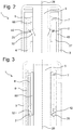
- Figure 2 shows a section through a proximal part of a drug delivery device 1 according to Figure 1 comprising a feedback feature 2.
- a first feedback element 32 of the feedback feature 2 is arranged at the actuator 5.
- the first feedback element 32 is integrally formed with the actuator 5.
- the actuator 5 may be an injection-moulded part, wherein the first feedback element 32 may be integrally moulded with the actuator 5.
- the first feedback element 32 comprises at least one, in particular two resilient arms 20, which stick out from the actuator 5 in a radial direction.
- the resilient arms 20 stick out in a direction away from a longitudinal axis 26 of the drug delivery device 1.
- the resilient arms 20 may be configured as a snap feature.
- the resilient arms 20 are configured to snap over a second feedback element 42 of the feedback feature 2.
- each resilient arm 20 extends in a proximal direction.
- each resilient arm 20 has one connection point with a main body of the actuator 5 and one free end. The free end is faced towards a proximal end of the device 1.
- the driver 7 comprises a cavity 27, wherein the feedback feature 2, in particular the resilient arms 20, extend through the cavity 27.
- the actuator 5 When the actuator 5 is actuated by a user, the actuator 5 and thereby the first feedback element 32 is moved in a direction towards a distal end of the device 1. During the movement of the actuator 5 towards the distal end of the device 1, the first feedback element 32 interacts with the second feedback element 42.
- the second feedback element 42 is configured as a protrusion.
- the second feedback element 42 is located at the inner body 4.
- the second feedback element 42 may be configured as a full ring detent feature. This is beneficial in the case that the actuator 5 may have any rotational alignment relative to the inner body 4.
- the first feedback element 32 is deflected in a radial direction towards the longitudinal axis 26 of the device 1, i.e. radially inwards.
- the resilient arms 20 are deflected by the second feedback element 42.
- the resilient arms 20 lose contact with the second feedback element 42 and snap back in a direction away from the longitudinal axis 26 of the device 1. Thereby, an audible and/or tactile feedback is created.
- the first feedback element 32, in particular the resilient arms 20, may be located on the inner body 4, and the second feedback element 42 may be located on the actuator 5.
- the resilient arms 20 are again deflected radially inwards by the second feedback element 32. Thereby, the resilient arms 20 may slide back over the second feedback element 42 such that they are again in a proximal position relative to the second feedback element 42.
- Figure 3 shows a section through a proximal part of a further embodiment of a drug delivery device 1 with a feedback feature 2.
- the feedback feature 2 comprises a first feedback element 32 and a second feedback element 42.
- the first feedback element 32 is located at the inner body 4.
- the first feedback element 32 comprises two resilient arms 20.
- the resilient arms 20 stick out from the inner body 4 in a radial direction towards the longitudinal axis 26 of the drug delivery device 1.
- the resilient arms 20 extend in a proximal direction.
- the second feedback element 42 is located at the driver 7.
- the second feedback element 32 is configured as a protrusion on the driver 7. Since the driver 7 can have any rotational alignment to the inner body 4, the second feedback element 42 may be configured as a full ring detent feature.
- the operating principle is similar to the embodiment described in Figure 2 .
- the driver 7 is also moved towards the distal end of the device.
- the first feedback element 32 in particular the resilient arms 20
- the first feedback element 32 in particular the resilient arms 20
- an audible and/or tactile feedback is created.
- the first feedback element 32, in particular the resilient arms 20 may be located at the driver 7, and the second feedback element 42 may be located at the inner body 4.
- the resilient arms 20 are again deflected radially outwards by the second feedback element 42. Thereby, the resilient arms 20 may slide back over the second feedback element 42 such that they are again in a distal position relative to the second feedback element 42.
- Figures 4A and 4B show a section through a proximal part of a further embodiment of a drug delivery device 1 comprising a feedback feature 2.
- the feedback feature 2 comprises a first feedback element 32 and a second feedback element 42.
- the first feedback element 32 is arranged at the indicator 6.
- the first feedback element 32 may be an integral part of the indicator 6.
- the first feedback element 32 extends along a circumferential direction of the indicator 6.
- the first feedback element 32 comprises a resilient arm 20.
- the first feedback element 32 in particular the resilient arm 20 interacts with a second feedback element (not shown) inside the actuator 5 to provide an audible click with each unit dispensed.
- the second feedback element inside the actuator 5 may comprise, for example, teeth or splines.
- an enhancement feature 23 is arranged at the inner body 4.
- the enhancement feature 23 is configured to interact with the first feedback element 32.
- Figure 4B shows the interaction of the first feedback element 32 and the enhancement feature 23.
- the enhancement feature 23 interacts with the first feedback element 32 at the end of a dispense operation. Due to the interaction of the first feedback element 32 and the enhancement feature 23, support is provided to the first feedback element 32 at least when the final unit of a dose is injected.
- the enhancement feature 23 interacts with the first feedback element 32 such that a deflection of the first feedback element 32 in a radially inward direction is limited. Thereby, the stiffness of the first feedback element 32 in particular of the resilient arm 20, is increased. Thereby, the interaction of the first feedback element 32 and the second feedback element inside the actuator 5 is increased. Thereby, a louder or a noticeably different click is produced, signalling to the user the end of a dispense operation.
- Figure 5 shows a further embodiment of a drug delivery device 1 comprising a feedback feature 2.
- the feedback feature 2 is configured as a snap feature.
- the feedback feature 2 is configured as a snap dome.
- the feedback feature 2 comprises or consists of a metal material.
- the feedback feature 2 comprises an opening 33, wherein the actuator 5 extends through the opening.
- a feedback feature 2 being configured as a snap dome is shown in Figure 6A .
- the feedback feature 2 is configured as an arched disc.
- the feedback feature 2 comprises at least one recess 34.
- the recess 34 is configured as a concave cavity.
- the feedback feature 2 comprises four recesses 34. Due to the cavities, the snap dome possesses a sufficient flexibility.
- the feedback feature 2 is configured to snap through when it is compressed above a certain load. Thereby, the feedback feature 2 creates an audible click and/or a tactile feedback at the end of a dispense operation.
- the feedback feature 2 is configured without any recess. Thereby, the feedback feature 2 may comprise a high stiffness. Thereby, the feedback signal may be more distinct.
- the feedback feature 2 is configured as an arched ring.
- the feedback feature 2 comprises an opening.
- the feedback feature 2 is operated by an axially moveable member 50.
- the axially moveable member 50 is a sleeve member 24 which is arranged between the actuator 5 and the indicator 6.
- the sleeve member 24 can move axially relative to the actuator 5 between two stops 35, 36 when it does not interact with the feedback feature 2.
- the feedback feature 2 pushes apart the actuator 5 and the sleeve member 24 to preload the sleeve member 24 against one of these stops 35, 36.
- one stop 35 is provided by the housing 3 and the other stop 36 is provided by the actuator 5.
- the sleeve member 24 contacts the stop 35 at the housing 3.
- the feedback feature 2 When the actuator 5 is further moved towards its end position, the feedback feature 2 is compressed. Thereby, the feedback feature 2 is caused to snap, thereby creating an audible click. In particular, a clear audible and tactile feedback is provided for a user at the end of a dispense operation.
- the feedback feature 2 When the load which is exerted on the feedback feature 2 by the sleeve member 24 is released during the setting of a dose, the feedback feature 2 snaps back into its uncompressed shape. Thereby, the feedback feature 2 may push the actuator 5 to an extended position.
- Figure 7 shows a section through a proximal part of a further embodiment of a drug delivery device 1 comprising a feedback feature 2.
- the embodiment shown in Figure 7 is similar to the embodiment shown in Figure 5 , apart from that the embodiment shown in Figure 7 does not comprise a sleeve member 24.
- the feedback feature 2 directly interacts with the actuator 5 and the housing 3.
- the housing 3 comprises a collar 37.
- the collar 37 is configured to interact with the feedback feature 2.
- the feedback feature 2 is compressed between the collar 37 of the housing 3 and the actuator 5 when the actuator 5 approaches the housing 3 during the dispensing of a dose.
- Figure 8 shows a proximal part of a different embodiment of a drug delivery device 1 comprising a feedback feature 2.
- the embodiment shown in Figure 8 is similar to the embodiment shown in Figure 5 , apart from that the feedback feature 2 is integrated into the axially moveable member 50, which is configured as a sleeve member 24.
- the sleeve member 24 may be an injection-moulded part, and the feedback feature 2 may be integrally moulded with the sleeve member 24.
- the feedback feature 2 may be configured as a plastic dome or a series of resilient arms. The resilient arms may be arched, such that they form a dome with slots.
- the operating principle is the same as in the embodiment shown in Figure 5 , with the feedback feature 2 snapping through, thereby creating an audible and/or tactile feedback for a user at the end of a dispense operation.
- Figure 9 shows a section through a proximal part of a further embodiment of the drug delivery device 1 comprising a feedback feature 2.
- the feedback feature 2 is arranged between the indicator 6 and the housing 3.
- the feedback feature 2 is positioned inside a cavity in the housing 3.
- the feedback feature 2 is configured as a snap dome with a relatively large diameter.
- the actuator 5, the driver 7, the inner body 4 and a part of the housing 3 extend through the opening.
- the indicator 6 When the indicator 6 approaches its end-of-dispense position, it makes contact with the feedback feature 2 and compresses the feedback feature 2, thereby causing it to undergo snap-through buckling. Thereby, an audible and/or tactile feedback is created to indicate the end of a dispense operation to a user.
- Figure 10 shows a section through a proximal part of a further embodiment of a drug delivery device 1 comprising a feedback feature 2.
- the embodiment shown in Figure 10 is similar to the embodiment shown in Figure 9 , apart from that the feedback feature 2 is arranged between the driver 7 and the inner body 4.
- the feedback feature 2 is arranged on a protrusion 31 of the inner body 4.
- the driver 7 approaches its end-of-dispense position, it makes contact with the feedback feature 2 and compresses the feedback feature 2, thereby causing the feedback feature 2 to snap through. Thereby, an audible and/or tactile feedback is created, indicating the end of a dispense operation to a user.
- FIG 11A shows the actuator 5, the indicator 6 and the inner body 4 of a drug delivery device 1 according to Figure 1 .
- the indicator 6 comprises a first feedback element 32, which is configured as a resilient arm 20.
- the first feedback element 32 extends along a circumferential direction of the indicator 6.
- the feedback feature 2, in particular the resilient arm 20, is arranged at a distal end of the indicator 6.
- a thread 28, which is configured to interact with the feedback feature 2 is formed on the inner body 4.
- a second feedback element 42 is formed in the thread 28.
- the second feedback element 42 is configured as a step 29 in the thread 28.
- the resilient arm 20 passes over the step 29. When the resilient arm 20 passes over the step 29, it is preloaded in an axial direction.
- the resilient arm 20 is preloaded in a direction towards the proximal end of the device 1. This preload could be retained throughout the travel of the indicator 6. Alternatively, the thread pitch could alter such that the resilient arm 20 is preloaded near to the end of the dispense operation. As a result of this preload, the resilient arm 20 accelerates rapidly as it drops off the step 29. Thereby, the resilient arm 20 strikes the thread wall 30 near the bottom of the step 29. Thereby, and audible and/or tactile signal is created, which indicates the end of a dispense operation to a user.
- Figure 11B shows a section of the inner body 4 showing the step 29 in the thread 28 in more detail.
- Figure 12A shows the actuator 5, the indicator 6 and the inner body 4 of a drug delivery device 1 according to Figure 1 .
- the embodiment according to Figure 12A is similar to the embodiment shown in Figure 11A .
- the indicator 6 also comprises a first feedback element 32 comprising a resilient arm 20, which is configured to interact with a thread 28 formed on the inner body 4.
- the resilient arm 20 is configured to be preloaded radially outwards by the floor of the thread 28. This preload could be retained throughout the travel of the indicator 6. Alternatively, the preload could be generated when the indicator 6 is approaching its end of dispense position. In particular, the floor of the thread 28 could be raised such that the resilient arm 20 is preloaded near the end of the dispense operation.
- the second feedback element 42, or the step 29, respectively is radial, causing the resilient arm 20 to accelerate radially inwards and hit the inner body 4.
- Figure 12B shows a section of the inner body 4 showing the step 29 in the thread 28 in more detail.
Abstract
Description
- The present disclosure relates to an assembly for a drug delivery device. The assembly comprises a feedback feature.
- It is an object of the present invention to provide an assembly for a drug delivery device having improved properties.
- An assembly for a drug delivery device is provided, the assembly comprising a feedback feature. The feedback feature is configured to indicate an end of a dispense operation to a user by giving an audible and/or tactile feedback. The audible feedback may be, for example, an audible click. The tactile feedback may be, for example, an impact on the skin of a user, in particular on a user's finger. For example, the tactile feedback may be a vibration of a part of the assembly. In particular, the feedback may be a well-defined signal. In particular, the feedback may indicate to a user that the actuator may be released and the device may be withdrawn from a user's skin.
- The advantage of a feedback feature being configured to indicate the end of a dispense operation is that a clear indication is given to a user when a dispense operation has been completed. Thereby, the use of the drug delivery device may be simplified for a user. Furthermore, the dosing accuracy of a drug delivery device may be increased. In particular, it may be inhibited that a user interrupts a dispense operation, for example by withdrawing the drug delivery device from the skin, before a complete dose has been delivered. Furthermore, such a feedback provides an additional benefit for visually impaired users.
- According to one embodiment, the assembly comprises an actuator, which is configured to be operated by a user in order to dispense a dose. A feedback feature may create a feedback when the actuator reaches an end position at the end of a dispense operation. The end position of the actuator may be a most distal position of the actuator. The term "most distal position" may describe a position of a part of the assembly which is closest to a dispensing end of the drug delivery device. In particular, the actuator may be in its end position when it is fully depressed into the drug delivery device. The actuator may be configured as a button. According to one embodiment, the feedback feature may be an integral part of the actuator.
- According to one embodiment, the assembly comprises a member which is configured to interact with the feedback feature. The member is configured to axially move when it does not interact with the feedback feature. For example, the member is configured to axially move during an initial phase of a dispense operation. The interaction of the axially moveable member with the feedback feature may cause a feedback. According to another embodiment, the member may be a driver. The driver may be a part of the assembly which is configured to drive a piston rod in order to dispense a dose of medication. In particular, the driver may be engaged with the piston rod. During a dispense operation, the driver may be moved towards a distal end of the device due to a movement of the actuator. According to a further embodiment, the member may be an indicator, for example a number sleeve. According to a further embodiment, the member may be a separate member, for example a sleeve member.
- According to one embodiment, the member may axially move with respect to a housing of the drug delivery device between two stops at least during the setting of a dose. During the dispensing of a dose, in particular when the actuator approaches its end position, the member may be temporarily restrained between these two stops. Thereby, the member may be temporarily axially fixed. In particular, the member may be axially fixed when it interacts with the feedback feature, i. e. when the actuator contacts the feedback feature.
- According to one embodiment, the feedback feature is configured to snap through when it is compressed above a certain load. Thereby, a feedback may be given to a user. In particular, the feedback feature is configured to snap through at the end of a dispense operation. In particular, the feedback feature is configured to snap through when the actuator reaches its end position. Initially during compression of the feedback feature, the stiffness of the feedback feature may remain fairly constant. At a certain point, the stiffness of the feedback feature may reduce significantly. Thereby, the force required to cause a further deflection of the feedback feature may decrease. This may cause the snap-through behaviour of the feedback feature.
- According to one embodiment, the feedback feature may be configured to be compressed between two parts of the assembly. For example, the feedback feature may be compressed between the actuator and the axially moveable member. Alternatively, the feedback feature could be compressed between the housing and the driver.
- According to one embodiment, the feedback feature may comprise the shape of a dome. In particular, the feedback feature may be configured as a snap dome. In particular, the feedback feature may comprise the shape of an arched disk.
- According to one embodiment, the feedback feature comprises at least one recess. The recess may be, for example, a concave cut out. Due to the at least one recess, the feedback feature may comprise a sufficient flexibility. Thereby, the feedback feature may be configured to snap through when it is compressed above a certain load. In particular, the size and shape of the recess may influence the force which is necessary to cause the feedback feature to snap through.
- According to one embodiment, the actuator interacts with the feedback feature. In particular, the actuator may interact with the feedback feature during a dispense operation. The feedback feature may be arranged between the actuator and another part of the drug delivery device. When the actuator approaches its end position during a dispense operation, the feedback feature may be clamped between the actuator and the other part. When the actuator is further moved towards the other part, the feedback feature may be compressed by the actuator. In particular, the force on the feedback feature increases when the actuator is further moved towards the other part. In particular, the actuator may exert a force on the feedback feature during a dispense operation. In an alternative embodiment, the feedback feature may be an integral part of the other part.
- According to one embodiment, the feedback feature comprises a metal material. According to a further embodiment, the feedback feature may comprise a plastic material. Preferably, the feedback feature comprises a resilient material.
- According to one embodiment, the feedback feature comprises an opening, wherein at least one element of the assembly extends through the opening. For example, the actuator may extend through the opening of the feedback feature. As a further example, the driver may extend through the opening of the feedback feature.
- According to one embodiment, the feedback feature comprises a first feedback element and a second feedback element. The first feedback element may be configured to interact with the second feedback element. In particular, the first feedback element and the second feedback element may abut each other, in particular when the actuator approaches its end position. In particular, the second feedback element may exert a force on the first feedback element during the dispensing of a dose. Thereby, the first feedback element may be deflected by the second feedback element during a dispense operation. The first feedback element may be, for example, a resilient element. The second feedback element may be, for example, a rigid element. For example, the second feedback element may be a protrusion in a part of the assembly. In particular, the second feedback element may extend along the whole circumference of the part. For example, the second feedback element may be a protrusion which extends along an inner circumference of a body part of the assembly. When the first feedback element and the second feedback element interact with each other, an audible feedback may be created. The first feedback element may be an integral part of a part of the device. For example, the first feedback element may be an integral part of the actuator. Alternatively, the first feedback element may be an integral part of the indicator.
- According to one embodiment, the feedback feature comprises at least one resilient arm. In particular, the first feedback element may comprise at least one resilient arm. Preferably, the feedback feature comprises two or more resilient arms. Preferably, the at least one resilient arm extends in a proximal direction. The proximal direction may be a direction away from the dispensing end of the device. In an alternative embodiment, the at least one resilient arm extends in a distal direction. According to one embodiment, the at least one resilient arm may stick out from an element of the assembly in a radial direction. During a dispense operation, the at least one resilient arm may be deflected, in particular in a radial direction. Preferably, the at least one resilient arm is integrally formed with a part of the assembly. Preferably, the at least one arm is attached to, in particular integrally moulded with an injection moulded part of the device.
- According to one embodiment, the assembly comprises a rotation member which is configured to rotate during dispensing of a dose. The first feedback element of the feedback feature may be located at the rotation member. The rotation member may be, for example, an indicator, in particular a number sleeve. For example, the feedback feature may be a resilient arm which is attached to the rotation member. In particular, the feedback element may extend along a circumferential direction of the rotation member. Preferably, the feedback feature is configured to be deflected in a radial inward direction.
- According to one embodiment, the feedback feature is configured to give a feedback to a user during the dispensing of a dose. In particular, the feedback may indicate that the dispensing is ongoing. As an example, a first feedback element may permanently interact with a second feedback element during a dispense operation. At the end of a dispense operation, the feedback may be increased.
- According to one embodiment, the assembly comprises an enhancement feature. The enhancement feature may be configured to enhance a feedback signal. The enhancement feature may be, for example, a protrusion in one part of the assembly. According to one embodiment, the first feedback element is configured to interact with the enhancement feature at the end of the dispense operation. Preferably, the first feedback element does not interact with the enhancement feature prior to the end of the dispense operation. The enhancement feature may be configured to reinforce the interaction of the first feedback element with the second feedback element. The second feedback element may comprise a plurality of protrusions or splines. For example, the enhancement feature may increase the stiffness of the first feedback element. In particular, the enhancement feature may be in contact with the first feedback element at the end of a dispense operation. In particular, the enhancement feature may be in contact with a surface of the first feedback element which is faced towards a longitudinal axis of the device. Thereby, the enhancement feature may limit a deflection of the first feedback element, in particular in a radially inward direction.
- According to one embodiment, the second feedback element is configured as a thread. For example, the second feedback element may comprise a thread in a body part of the assembly. The first feedback element may be a resilient arm, which is for example located at the rotation member and may extend along a circumference direction of the rotation member. During the dispensing of a dose, the first feedback element may interact with the thread of the second feedback element. In particular, the first feedback element may be preloaded due to the interaction with the thread of the second feedback element. For example, the first feedback element may be strained in an axial or radial direction. The second feedback element may further comprise a step. The step may be located at a distal end of the thread. The step may extend in an axial or radial direction. When the first feedback element reaches the step at the end of a dispense operation, the first feedback element may, due to its preload, drop of the step. Thereby, the first feedback element may hit the wall of the body part. Thereby, an audible feedback may be created.
- Furthermore, a drug delivery device is provided, the drug delivery device comprising an assembly which is configured as previously described. In particular, the drug delivery device may comprise a feedback feature, which is configured to indicate an end of a dispense operation to a user by giving an audible and/or tactile feedback.
- The drug delivery device may be an injection device. The drug delivery device may be a pen-type device. The drug delivery device may be a variable dose device such that a user can select the size of a dose. The drug delivery device may be configured for multiple dose applications. The medication may be delivered to a user by means of a needle. The device may be delivered to a user in a fully assembled condition ready for use. The drug delivery device may be a disposable device. The term "disposable" means that the drug delivery device cannot be reused after an available amount of medication has been delivered from the drug delivery device. The drug delivery device may be configured to deliver a liquid medication. The medication may be, for example, insulin.
- The term "medication", as used herein, preferably means a pharmaceutical formulation containing at least one pharmaceutically active compound,
wherein in one embodiment the pharmaceutically active compound has a molecular weight up to 1500 Da and/or is a peptide, a proteine, a polysaccharide, a vaccine, a DNA, a RNA, an enzyme, an antibody or a fragment thereof, a hormone or an oligonucleotide, or a mixture of the above-mentioned pharmaceutically active compound,
wherein in a further embodiment the pharmaceutically active compound is useful for the treatment and/or prophylaxis of diabetes mellitus or complications associated with diabetes mellitus such as diabetic retinopathy, thromboembolism disorders such as deep vein or pulmonary thromboembolism, acute coronary syndrome (ACS), angina, myocardial infarction, cancer, macular degeneration, inflammation, hay fever, atherosclerosis and/or rheumatoid arthritis,
wherein in a further embodiment the pharmaceutically active compound comprises at least one peptide for the treatment and/or prophylaxis of diabetes mellitus or complications associated with diabetes mellitus such as diabetic retinopathy,
wherein in a further embodiment the pharmaceutically active compound comprises at least one human insulin or a human insulin analogue or derivative, glucagon-like peptide (GLP-1) or an analogue or derivative thereof, or exendin-3 or exendin-4 or an analogue or derivative of exendin-3 or exendin-4. - Insulin analogues are for example Gly(A21), Arg(B31), Arg(B32) human insulin; Lys(B3), Glu(B29) human insulin; Lys(B28), Pro(B29) human insulin; Asp(B28) human insulin; human insulin, wherein proline in position B28 is replaced by Asp, Lys, Leu, Val or Ala and wherein in position B29 Lys may be replaced by Pro; Ala(B26) human insulin; Des(B28-B30) human insulin; Des(B27) human insulin and Des(B30) human insulin.
- Insulin derivates are for example B29-N-myristoyl-des(B30) human insulin; B29-N-palmitoyl-des(B30) human insulin; B29-N-myristoyl human insulin; B29-N-palmitoyl human insulin; B28-N-myristoyl LysB28ProB29 human insulin; B28-N-palmitoyl-LysB28ProB29 human insulin; B30-N-myristoyl-ThrB29LysB30 human insulin; B30-N-palmitoyl- ThrB29LysB30 human insulin; B29-N-(N-palmitoyl-Y-glutamyl)-des(B30) human insulin; B29-N-(N-lithocholyl-Y-glutamyl)-des(B30) human insulin; B29-N-(ω-carboxyheptadecanoyl)-des(B30) human insulin and B29-N-(ω-carboxyheptadecanoyl) human insulin.
- Exendin-4 for example means Exendin-4(1-39), a peptide of the sequence H-His-Gly-Glu-Gly-Thr-Phe-Thr-Ser-Asp-Leu-Ser-Lys-Gln-Met-Glu-Glu-Glu-Ala-Val-Arg-Leu-Phe-Ile-Glu-Trp-Leu-Lys-Asn-Gly-Gly-Pro-Ser-Ser-Gly-Ala-Pro-Pro-Pro-Ser-NH2.
- Exendin-4 derivatives are for example selected from the following list of compounds:
- H-(Lys)4-des Pro36, des Pro37 Exendin-4(1-39)-NH2,
- H-(Lys)5-des Pro36, des Pro37 Exendin-4(1-39)-NH2,
- des Pro36 Exendin-4(1-39),
- des Pro36 [Asp28] Exendin-4(1-39),
- des Pro36 [IsoAsp28] Exendin-4(1-39),
- des Pro36 [Met(O)14, Asp28] Exendin-4(1-39),
- des Pro36 [Met(O)14, IsoAsp28] Exendin-4(1-39),
- des Pro36 [Trp(O2)25, Asp28] Exendin-4(1-39),
- des Pro36 [Trp(O2)25, IsoAsp28] Exendin-4(1-39),
- des Pro36 [Met(O)14 Trp(O2)25, Asp28] Exendin-4(1-39),
- des Pro36 [Met(O)14 Trp(O2)25, IsoAsp28] Exendin-4(1-39); or
- des Pro36 [Asp28] Exendin-4(1-39),
- des Pro36 [IsoAsp28] Exendin-4(1-39),
- des Pro36 [Met(O)14, Asp28] Exendin-4(1-39),
- des Pro36 [Met(O)14, IsoAsp28] Exendin-4(1-39),
- des Pro36 [Trp(O2)25, Asp28] Exendin-4(1-39),
- des Pro36 [Trp(O2)25, IsoAsp28] Exendin-4(1-39),
- des Pro36 [Met(O)14 Trp(O2)25, Asp28] Exendin-4(1-39),
- des Pro36 [Met(O)14 Trp(O2)25, IsoAsp28] Exendin-4(1-39),
- wherein the group -Lys6-NH2 may be bound to the C-terminus of the Exendin-4 derivative;
- or an Exendin-4 derivative of the sequence
- des Pro36 Exendin-4(1-39)-Lys6-NH2 (AVE0010),
- H-(Lys)6-des Pro36 [Asp28] Exendin-4(1-39)-Lys6-NH2,
- des Asp28 Pro36, Pro37, Pro38Exendin-4(1-39)-NH2,
- H-(Lys)6-des Pro36, Pro38 [Asp28] Exendin-4(1-39)-NH2,
- H-Asn-(Glu)5des Pro36, Pro37, Pro38 [Asp28] Exendin-4(1-39)-NH2,
- des Pro36, Pro37, Pro38 [Asp28] Exendin-4(1-39)-(Lys)6-NH2,
- H-(Lys)6-des Pro36, Pro37, Pro38 [Asp28] Exendin-4(1-39)-(Lys)6-NH2,
- H-Asn-(Glu)5-des Pro36, Pro37, Pro38 [Asp28] Exendin-4(1-39)-(Lys)6-NH2,
- H-(Lys)6-des Pro36 [Trp(O2)25, Asp28] Exendin-4(1-39)-Lys6-NH2,
- H-des Asp28 Pro36, Pro37, Pro38 [Trp(O2)25] Exendin-4(1-39)-NH2,
- H-(Lys)6-des Pro36, Pro37, Pro38 [Trp(O2)25, Asp28] Exendin-4(1-39)-NH2,
- H-Asn-(Glu)5-des Pro36, Pro37, Pro38 [Trp(O2)25, Asp28] Exendin-4(1-39)-NH2,
- des Pro36, Pro37, Pro38 [Trp(O2)25, Asp28] Exendin-4(1-39)-(Lys)6-NH2,
- H-(Lys)6-des Pro36, Pro37, Pro38 [Trp(O2)25, Asp28] Exendin-4(1-39)-(Lys)6-NH2,
- H-Asn-(Glu)5-des Pro36, Pro37, Pro38 [Trp(O2)25, Asp28] Exendin-4(1-39)-(Lys)6-NH2,
- H-(Lys)6-des Pro36 [Met(O)14, Asp28] Exendin-4(1-39)-Lys6-NH2,
- des Met(O)14 Asp28 Pro36, Pro37, Pro38 Exendin-4(1-39)-NH2,
- H-(Lys)6-desPro36, Pro37, Pro38 [Met(O)14, Asp28] Exendin-4(1-39)-NH2,
- H-Asn-(Glu)5-des Pro36, Pro37, Pro38 [Met(O)14, Asp28] Exendin-4(1-39)-NH2,
- des Pro36, Pro37, Pro38 [Met(O)14, Asp28] Exendin-4(1-39)-(Lys)6-NH2,
- H-(Lys)6-des Pro36, Pro37, Pro38 [Met(O)14, Asp28] Exendin-4(1-39)-(Lys)6-NH2,
- H-Asn-(Glu)5 des Pro36, Pro37, Pro38 [Met(O)14, Asp28] Exendin-4(1-39)-(Lys)6-NH2,
- H-Lys6-des Pro36 [Met(O)14, Trp(O2)25, Asp28] Exendin-4(1-39)-Lys6-NH2,
- H-des Asp28 Pro36, Pro37, Pro38 [Met(O)14, Trp(O2)25] Exendin-4(1-39)-NH2,
- H-(Lys)6-des Pro36, Pro37, Pro38 [Met(O)14, Asp28] Exendin-4(1-39)-NH2,
- H-Asn-(Glu)5-des Pro36, Pro37, Pro38 [Met(O)14, Trp(O2)25, Asp28] Exendin-4(1-39)-NH2,
- des Pro36, Pro37, Pro38 [Met(O)14, Trp(O2)25, Asp28] Exendin-4(1-39)-(Lys)6-NH2,
- H-(Lys)6-des Pro36, Pro37, Pro38 [Met(O)14, Trp(O2)25, Asp28] Exendin-4(S1-39)-(Lys)6-NH2,
- H-Asn-(Glu)5-des Pro36, Pro37, Pro38 [Met(O)14, Trp(O2)25, Asp28] Exendin-4(1-39)-(Lys)6-NH2;
- Hormones are for example hypophysis hormones or hypothalamus hormones or regulatory active peptides and their antagonists as listed in Rote Liste, ed. 2008, , such as Gonadotropine (Follitropin, Lutropin, Choriongonadotropin, Menotropin), Somatropine (Somatropin), Desmopressin, Terlipressin, Gonadorelin, Triptorelin, Leuprorelin, Buserelin, Nafarelin, Goserelin.
- A polysaccharide is for example a glucosaminoglycane, a hyaluronic acid, a heparin, a low molecular weight heparin or an ultra low molecular weight heparin or a derivative thereof, or a sulphated, e.g. a poly-sulphated form of the above-mentioned polysaccharides, and/or a pharmaceutically acceptable salt thereof. An example of a pharmaceutically acceptable salt of a poly-sulphated low molecular weight heparin is enoxaparin sodium.
- Antibodies are globular plasma proteins (∼150 kDa) that are also known as immunoglobulins which share a basic structure. As they have sugar chains added to amino acid residues, they are glycoproteins. The basic functional unit of each antibody is an immunoglobulin (Ig) monomer (containing only one Ig unit); secreted antibodies can also be dimeric with two Ig units as with IgA, tetrameric with four Ig units like teleost fish IgM, or pentameric with five Ig units, like mammalian IgM.
- The Ig monomer is a "Y"-shaped molecule that consists of four polypeptide chains; two identical heavy chains and two identical light chains connected by disulfide bonds between cysteine residues. Each heavy chain is about 440 amino acids long; each light chain is about 220 amino acids long. Heavy and light chains each contain intrachain disulfide bonds which stabilize their folding. Each chain is composed of structural domains called Ig domains. These domains contain about 70-110 amino acids and are classified into different categories (for example, variable or V, and constant or C) according to their size and function. They have a characteristic immunoglobulin fold in which two β sheets create a "sandwich" shape, held together by interactions between conserved cysteines and other charged amino acids.
- There are five types of mammalian Ig heavy chain denoted by α, δ, ε, γ, and µ. The type of heavy chain present defines the isotype of antibody; these chains are found in IgA, IgD, IgE, IgG, and IgM antibodies, respectively.
- Distinct heavy chains differ in size and composition; α and γ contain approximately 450 amino acids and δ approximately 500 amino acids, while µ and ε have approximately 550 amino acids. Each heavy chain has two regions, the constant region (CH) and the variable region (VH). In one species, the constant region is essentially identical in all antibodies of the same isotype, but differs in antibodies of different isotypes. Heavy chains γ, α and δ have a constant region composed of three tandem Ig domains, and a hinge region for added flexibility; heavy chains µ and ε have a constant region composed of four immunoglobulin domains. The variable region of the heavy chain differs in antibodies produced by different B cells, but is the same for all antibodies produced by a single B cell or B cell clone. The variable region of each heavy chain is approximately 110 amino acids long and is composed of a single Ig domain.
- In mammals, there are two types of immunoglobulin light chain denoted by λ and κ. A light chain has two successive domains: one constant domain (CL) and one variable domain (VL). The approximate length of a light chain is 211 to 217 amino acids. Each antibody contains two light chains that are always identical; only one type of light chain, κ or λ, is present per antibody in mammals.
- Although the general structure of all antibodies is very similar, the unique property of a given antibody is determined by the variable (V) regions, as detailed above. More specifically, variable loops, three each the light (VL) and three on the heavy (VH) chain, are responsible for binding to the antigen, i.e. for its antigen specificity. These loops are referred to as the Complementarity Determining Regions (CDRs). Because CDRs from both VH and VL domains contribute to the antigen-binding site, it is the combination of the heavy and the light chains, and not either alone, that determines the final antigen specificity.
- An "antibody fragment" contains at least one antigen binding fragment as defined above, and exhibits essentially the same function and specificity as the complete antibody of which the fragment is derived from. Limited proteolytic digestion with papain cleaves the Ig prototype into three fragments. Two identical amino terminal fragments, each containing one entire L chain and about half an H chain, are the antigen binding fragments (Fab). The third fragment, similar in size but containing the carboxyl terminal half of both heavy chains with their interchain disulfide bond, is the crystalizable fragment (Fc). The Fc contains carbohydrates, complement-binding, and FcR-binding sites. Limited pepsin digestion yields a single F(ab')2 fragment containing both Fab pieces and the hinge region, including the H-H interchain disulfide bond. F(ab')2 is divalent for antigen binding. The disulfide bond of F(ab')2 may be cleaved in order to obtain Fab'. Moreover, the variable regions of the heavy and light chains can be fused together to form a single chain variable fragment (scFv).
- Pharmaceutically acceptable salts are for example acid addition salts and basic salts. Acid addition salts are e.g. HCI or HBr salts. Basic salts are e.g. salts having a cation selected from alkali or alkaline, e.g. Na+, or K+, or Ca2+, or an ammonium ion N+(R1)(R2)(R3)(R4), wherein R1 to R4 independently of each other mean: hydrogen, an optionally substituted C1-C6-alkyl group, an optionally substituted C2-C6-alkenyl group, an optionally substituted C6-C10-aryl group, or an optionally substituted C6-C10-heteroaryl group. Further examples of pharmaceutically acceptable salts are described in "Remington's Pharmaceutical Sciences" 17. ed. Alfonso R. Gennaro (Ed.), Mark Publishing Company, Easton, Pa., U.S.A., 1985 and in Encyclopedia of Pharmaceutical Technology.
- Pharmaceutically acceptable solvates are for example hydrates.
- Further features, refinements and expediencies become apparent from the following description of the exemplary embodiments in connection with the figures.
-
Figure 1 shows a sectional view of a drug delivery device, -
Figure 2 shows a proximal part of a drug delivery device, -
Figure 3 shows a proximal part of a further embodiment of a drug delivery device, -
Figures 4A and 4B show a proximal part of a further embodiment of a drug delivery device, -
Figure 5 shows a proximal part of a further embodiment of a drug delivery device, -
Figure 6A shows a schematic view of a feedback feature, -
Figure 6B shows a schematic view of a further feedback feature, -
Figure 7 shows a proximal part of a further embodiment of a drug delivery device, -
Figure 8 shows a proximal part of a further embodiment of a drug delivery device, -
Figure 9 shows a proximal part of a further embodiment of a drug delivery device, -
Figure 10 shows a proximal part of a further embodiment of a drug delivery device, -
Figure 11A shows a schematic view of an assembly for a drug delivery device, -
Figure 11B shows a section of an inner body of the assembly ofFigure 11A , -
Figure 12A shows a schematic view of a further assembly for a drug delivery device, -
Figure 12B shows a section of an inner body of the assembly ofFigure 12A . -
Figure 1 shows adrug delivery device 1. In particular, thedrug delivery device 1 is an injection device. Thedrug delivery device 1 is a variable dose device such that a user can select the size of a dose. Thedrug delivery device 1 is configured for multiple dose applications. The device can be delivered to a user in a fully assembled condition ready for use. The device has a low part count and is particularly attractive for cost-sensitive device applications. - The
drug delivery device 1 comprises ahousing 3, aninner body 4, anactuator 5, anindicator 6, adriver 7, apiston rod 9, apiston 10, alast dose stop 11, and acartridge 13. A needle arrangement comprising a needle hub and a needle cover may be provided as additional components. - The
housing 3 is a generally tubular element. A distal part of thehousing 3 forms acartridge holder 14 for receiving thecartridge 13. - The
inner body 4 is a generally tubular element. Theinner body 4 is received in thehousing 3 and is permanently fixed therein to prevent any relative movement of theinner body 4 with respect to thehousing 3. Anexternal thread 15 is provided on the outer surface of theinner body 4. At its distal end, theinner body 4 comprises afurther thread 16. - The
actuator 5 is configured as a button. Theactuator 5 is rotationally and axially moveable with respect to thehousing 3 and theinner body 4. Theactuator 5 is arranged at a proximal end of thedrug delivery device 1. Theactuator 5 is configured to be operated in order to dispense a dose of medication. - The
indicator 6 is a generally tubular element. In particular, theindicator 6 is configured as arotation member 43. In particular, theindicator 6 is configured to rotate with respect to thehousing 3 during the setting and the dispensing of a dose. Theindicator 6 is arranged concentrically around theinner body 4. In particular, theindicator 6 comprises aninternal thread 19 engaging with theexternal thread 15 of theinner body 4. Thus, theindicator 6 is arranged between theinner body 4 and thehousing 3. A series of numbers is provided, e.g. printed, on the outer surface of theindicator 6. The numbers are arranged on a helical line such that only one number or only a few numbers are visible through awindow 12 of thehousing 3. The numbers indicate the amount of a set dose. At the end of a dose dispense operation, theindicator 6 may have returned in its initial position, thereby indicating the end of a dispense operation to a user. - The
piston rod 9 is configured as a lead screw. In particular, thepiston rod 9 comprises two counter-handed threads which overlap each other. One of the threads of thepiston rod 9 engages with theinner thread 16 of theinner body 4. - The
driver 7 is a generally tubular element. An inner surface of thedriver 7 has aninner thread 18 engaging with one of the external threads of thepiston rod 9. Thedriver 7 is at least partly located within theinner body 4. A distal region of thedriver 7 has anexternal thread 17. Thedriver 7 is configured to rotate and axially move with respect to thehousing 3 during the setting of a dose. During the dispensing of a dose, thedriver 7 is axially moveable and rotationally fixed with respect to thehousing 3. - The
last dose stop 11 is provided between theinner body 4 and thedriver 7. An internal thread of thelast dose stop 11 engages with theexternal thread 17 of thedriver 7. Thelast dose stop 11 is configured to inhibit the setting of a dose which is larger than an amount of medication remaining in thecartridge 13. This is achieved by thelast dose stop 11 abutting an abutment feature of thedriver 7 when a dose is set which corresponds to an amount of medication remaining in thecartridge 13. Thelast dose stop 11 is configured as a nut. - In order to set a dose, the
actuator 5 is rotated by a user. During the setting of a dose, theindicator 6 and thedriver 7 are rotationally fixed with respect to theactuator 5. Thereby, theactuator 5, theindicator 6 and thedriver 7 are rotated out of thehousing 3. Thereby, thedriver 7 is rotated along thepiston rod 9 in a proximal direction, while thepiston rod 9 is axially and rotationally fixed with respect to thehousing 3 during the setting of a dose. Theindicator 6 is rotated along thethread 15 of theinner body 4. - In order to dispense a dose, the
actuator 5 is operated by a user. In particular, theactuator 5 is pushed in a direction towards a dispensing end of the device. During the dispensing of a dose, theactuator 5 and thedriver 7 are rotationally fixed with respect to each other. Theindicator 6 may rotate with respect to theactuator 5 and thedriver 6 during the dispensing of a dose. Thereby, theindicator 6 may rotate back to its initial position and indicate the end of the dispense operation to a user. When theactuator 5 is operated, thedriver 7 is also moved in a direction towards a dispensing end of the device. Thereby, thepiston rod 9 is axially moved in a distal direction in order to dispense a dose of medication. In particular, thepiston rod 9 is configured to rotate and axially move during the dispensing of a dose. When theactuator 5 has been operated and reached an end position, a feedback is given to a user. In particular, the feedback may indicate the end of a dispense operation. The end position of theactuator 5 may be its most distal position. In particular, theactuator 5 is in its end position when it is fully depressed. - In
Figures 2 to 12B , different embodiments of a feedback feature are shown, which may indicate an end of a dispense operation to a user. In particular,Figures 2 to 5 and7 to 12B showdifferent assemblies 60 for adrug delivery device 1 comprising different embodiments of afeedback feature 2. The embodiments are illustrated in the context of adrug delivery device 1 as shown inFigure 1 , but are not limited thereto. In particular, thefeedback feature 2 may also be used in a reusable device or in a device having a different drive mechanism. - The feedback may be an audible or tactile signal at the end of a dispense operation. This may improve the ease of use and the dose accuracy for a user, in particular for a visually impaired user. Furthermore, the signal can be used to indicate the start of a dwell period. At the end of a dispense operation, i. e. after a user has operated the
actuator 5, the dispensing of the full amount of a set dose may be delayed due to a slight deformation of thepiston 10. The dwell period is the time between the moment when theactuator 5 has reached its end position and the moment when the full amount of a dose has been dispensed. In particular, the dwell period may be the time thepiston 10 needs after an operation of theactuator 5 to relax to its undeformed state. -
Figure 2 shows a section through a proximal part of adrug delivery device 1 according toFigure 1 comprising afeedback feature 2. Afirst feedback element 32 of thefeedback feature 2 is arranged at theactuator 5. Thefirst feedback element 32 is integrally formed with theactuator 5. In particular, theactuator 5 may be an injection-moulded part, wherein thefirst feedback element 32 may be integrally moulded with theactuator 5. Thefirst feedback element 32 comprises at least one, in particular tworesilient arms 20, which stick out from theactuator 5 in a radial direction. In particular, theresilient arms 20 stick out in a direction away from alongitudinal axis 26 of thedrug delivery device 1. Theresilient arms 20 may be configured as a snap feature. In particular, theresilient arms 20 are configured to snap over asecond feedback element 42 of thefeedback feature 2. Theresilient arms 20 extend in a proximal direction. In particular, eachresilient arm 20 has one connection point with a main body of theactuator 5 and one free end. The free end is faced towards a proximal end of thedevice 1. Thedriver 7 comprises acavity 27, wherein thefeedback feature 2, in particular theresilient arms 20, extend through thecavity 27. - When the
actuator 5 is actuated by a user, theactuator 5 and thereby thefirst feedback element 32 is moved in a direction towards a distal end of thedevice 1. During the movement of theactuator 5 towards the distal end of thedevice 1, thefirst feedback element 32 interacts with thesecond feedback element 42. Thesecond feedback element 42 is configured as a protrusion. Thesecond feedback element 42 is located at theinner body 4. Thesecond feedback element 42 may be configured as a full ring detent feature. This is beneficial in the case that theactuator 5 may have any rotational alignment relative to theinner body 4. - During the movement of the
actuator 5 towards the distal end of thedevice 1, thefirst feedback element 32 is deflected in a radial direction towards thelongitudinal axis 26 of thedevice 1, i.e. radially inwards. In particular, theresilient arms 20 are deflected by thesecond feedback element 42. When theactuator 5 has reached its end position, in particular at the end of a dispense operation, theresilient arms 20 lose contact with thesecond feedback element 42 and snap back in a direction away from thelongitudinal axis 26 of thedevice 1. Thereby, an audible and/or tactile feedback is created. In an alternative embodiment, thefirst feedback element 32, in particular theresilient arms 20, may be located on theinner body 4, and thesecond feedback element 42 may be located on theactuator 5. - During the setting of a dose, when the
actuator 5 is moved in a direction away from the dispensing end of thedevice 1, theresilient arms 20 are again deflected radially inwards by thesecond feedback element 32. Thereby, theresilient arms 20 may slide back over thesecond feedback element 42 such that they are again in a proximal position relative to thesecond feedback element 42. -
Figure 3 shows a section through a proximal part of a further embodiment of adrug delivery device 1 with afeedback feature 2. Thefeedback feature 2 comprises afirst feedback element 32 and asecond feedback element 42. Thefirst feedback element 32 is located at theinner body 4. Thefirst feedback element 32 comprises tworesilient arms 20. Theresilient arms 20 stick out from theinner body 4 in a radial direction towards thelongitudinal axis 26 of thedrug delivery device 1. Theresilient arms 20 extend in a proximal direction. Thefirst feedback element 32, in particular theresilient arms 20, interact with thesecond feedback element 42. Thesecond feedback element 42 is located at thedriver 7. In particular, thesecond feedback element 32 is configured as a protrusion on thedriver 7. Since thedriver 7 can have any rotational alignment to theinner body 4, thesecond feedback element 42 may be configured as a full ring detent feature. - The operating principle is similar to the embodiment described in
Figure 2 . During the movement of theactuator 5 towards a distal end of the device, thedriver 7 is also moved towards the distal end of the device. Thereby, thefirst feedback element 32, in particular theresilient arms 20, are deflected in a radial direction away from thelongitudinal axis 26 of thedevice 1, i. e. radially outwards. When theactuator 5 has travelled its full distance, in particular at the end of a dispense operation, thefirst feedback element 32, in particular theresilient arms 20, lose contact with thesecond feedback element 42 of the driver and snap back in a direction towards thelongitudinal axis 26 of the device. Thereby, an audible and/or tactile feedback is created. In an alternative embodiment, thefirst feedback element 32, in particular theresilient arms 20, may be located at thedriver 7, and thesecond feedback element 42 may be located at theinner body 4. - During the setting of a dose, when the
actuator 5 is moved in a direction away from the dispensing end of thedevice 1, theresilient arms 20 are again deflected radially outwards by thesecond feedback element 42. Thereby, theresilient arms 20 may slide back over thesecond feedback element 42 such that they are again in a distal position relative to thesecond feedback element 42. -
Figures 4A and 4B show a section through a proximal part of a further embodiment of adrug delivery device 1 comprising afeedback feature 2. Thefeedback feature 2 comprises afirst feedback element 32 and asecond feedback element 42. - The
first feedback element 32 is arranged at theindicator 6. Thefirst feedback element 32 may be an integral part of theindicator 6. In particular, thefirst feedback element 32 extends along a circumferential direction of theindicator 6. In particular, thefirst feedback element 32 comprises aresilient arm 20. When theindicator 6 rotates relative to theactuator 5 and theinner body 4 during the dispensing of a dose, thefirst feedback element 32, in particular theresilient arm 20, interacts with a second feedback element (not shown) inside theactuator 5 to provide an audible click with each unit dispensed. The second feedback element inside theactuator 5 may comprise, for example, teeth or splines. At theinner body 4, anenhancement feature 23 is arranged. Theenhancement feature 23 is configured to interact with thefirst feedback element 32. -
Figure 4B shows the interaction of thefirst feedback element 32 and theenhancement feature 23. Theenhancement feature 23 interacts with thefirst feedback element 32 at the end of a dispense operation. Due to the interaction of thefirst feedback element 32 and theenhancement feature 23, support is provided to thefirst feedback element 32 at least when the final unit of a dose is injected. In particular, theenhancement feature 23 interacts with thefirst feedback element 32 such that a deflection of thefirst feedback element 32 in a radially inward direction is limited. Thereby, the stiffness of thefirst feedback element 32 in particular of theresilient arm 20, is increased. Thereby, the interaction of thefirst feedback element 32 and the second feedback element inside theactuator 5 is increased. Thereby, a louder or a noticeably different click is produced, signalling to the user the end of a dispense operation. -
Figure 5 shows a further embodiment of adrug delivery device 1 comprising afeedback feature 2. Thefeedback feature 2 is configured as a snap feature. In particular, thefeedback feature 2 is configured as a snap dome. Thefeedback feature 2 comprises or consists of a metal material. Thefeedback feature 2 comprises anopening 33, wherein theactuator 5 extends through the opening. - A
feedback feature 2 being configured as a snap dome is shown inFigure 6A . In particular, thefeedback feature 2 is configured as an arched disc. Furthermore, thefeedback feature 2 comprises at least onerecess 34. Therecess 34 is configured as a concave cavity. In particular, thefeedback feature 2 comprises fourrecesses 34. Due to the cavities, the snap dome possesses a sufficient flexibility. Thefeedback feature 2 is configured to snap through when it is compressed above a certain load. Thereby, thefeedback feature 2 creates an audible click and/or a tactile feedback at the end of a dispense operation. - In an alternative embodiment as shown in
Figure 6B , thefeedback feature 2 is configured without any recess. Thereby, thefeedback feature 2 may comprise a high stiffness. Thereby, the feedback signal may be more distinct. In particular, thefeedback feature 2 is configured as an arched ring. In particular, thefeedback feature 2 comprises an opening. - As illustrated in
Figure 5 , thefeedback feature 2 is operated by an axiallymoveable member 50. In particular, the axiallymoveable member 50 is asleeve member 24 which is arranged between theactuator 5 and theindicator 6. Thesleeve member 24 can move axially relative to theactuator 5 between twostops feedback feature 2. Thefeedback feature 2 pushes apart theactuator 5 and thesleeve member 24 to preload thesleeve member 24 against one of thesestops stop 35 is provided by thehousing 3 and theother stop 36 is provided by theactuator 5. When theactuator 5 approaches its end position, thesleeve member 24 contacts thestop 35 at thehousing 3. When theactuator 5 is further moved towards its end position, thefeedback feature 2 is compressed. Thereby, thefeedback feature 2 is caused to snap, thereby creating an audible click. In particular, a clear audible and tactile feedback is provided for a user at the end of a dispense operation. - When the load which is exerted on the
feedback feature 2 by thesleeve member 24 is released during the setting of a dose, thefeedback feature 2 snaps back into its uncompressed shape. Thereby, thefeedback feature 2 may push theactuator 5 to an extended position. -
Figure 7 shows a section through a proximal part of a further embodiment of adrug delivery device 1 comprising afeedback feature 2. The embodiment shown inFigure 7 is similar to the embodiment shown inFigure 5 , apart from that the embodiment shown inFigure 7 does not comprise asleeve member 24. Thefeedback feature 2 directly interacts with theactuator 5 and thehousing 3. In particular, thehousing 3 comprises acollar 37. Thecollar 37 is configured to interact with thefeedback feature 2. In particular, thefeedback feature 2 is compressed between thecollar 37 of thehousing 3 and theactuator 5 when theactuator 5 approaches thehousing 3 during the dispensing of a dose. -
Figure 8 shows a proximal part of a different embodiment of adrug delivery device 1 comprising afeedback feature 2. The embodiment shown inFigure 8 is similar to the embodiment shown inFigure 5 , apart from that thefeedback feature 2 is integrated into the axiallymoveable member 50, which is configured as asleeve member 24. In particular, thesleeve member 24 may be an injection-moulded part, and thefeedback feature 2 may be integrally moulded with thesleeve member 24. Thefeedback feature 2 may be configured as a plastic dome or a series of resilient arms. The resilient arms may be arched, such that they form a dome with slots. The operating principle is the same as in the embodiment shown inFigure 5 , with thefeedback feature 2 snapping through, thereby creating an audible and/or tactile feedback for a user at the end of a dispense operation. -
Figure 9 shows a section through a proximal part of a further embodiment of thedrug delivery device 1 comprising afeedback feature 2. Thefeedback feature 2 is arranged between theindicator 6 and thehousing 3. In particular, thefeedback feature 2 is positioned inside a cavity in thehousing 3. Thefeedback feature 2 is configured as a snap dome with a relatively large diameter. Theactuator 5, thedriver 7, theinner body 4 and a part of thehousing 3 extend through the opening. - When the
indicator 6 approaches its end-of-dispense position, it makes contact with thefeedback feature 2 and compresses thefeedback feature 2, thereby causing it to undergo snap-through buckling. Thereby, an audible and/or tactile feedback is created to indicate the end of a dispense operation to a user. -
Figure 10 shows a section through a proximal part of a further embodiment of adrug delivery device 1 comprising afeedback feature 2. The embodiment shown inFigure 10 is similar to the embodiment shown inFigure 9 , apart from that thefeedback feature 2 is arranged between thedriver 7 and theinner body 4. Thefeedback feature 2 is arranged on aprotrusion 31 of theinner body 4. When thedriver 7 approaches its end-of-dispense position, it makes contact with thefeedback feature 2 and compresses thefeedback feature 2, thereby causing thefeedback feature 2 to snap through. Thereby, an audible and/or tactile feedback is created, indicating the end of a dispense operation to a user. -
Figure 11A shows theactuator 5, theindicator 6 and theinner body 4 of adrug delivery device 1 according toFigure 1 . Theindicator 6 comprises afirst feedback element 32, which is configured as aresilient arm 20. Thefirst feedback element 32 extends along a circumferential direction of theindicator 6. Thefeedback feature 2, in particular theresilient arm 20, is arranged at a distal end of theindicator 6. Athread 28, which is configured to interact with thefeedback feature 2, is formed on theinner body 4. Asecond feedback element 42 is formed in thethread 28. Thesecond feedback element 42 is configured as astep 29 in thethread 28. At the end of a dispense operation, theresilient arm 20 passes over thestep 29. When theresilient arm 20 passes over thestep 29, it is preloaded in an axial direction. In particular, theresilient arm 20 is preloaded in a direction towards the proximal end of thedevice 1. This preload could be retained throughout the travel of theindicator 6. Alternatively, the thread pitch could alter such that theresilient arm 20 is preloaded near to the end of the dispense operation. As a result of this preload, theresilient arm 20 accelerates rapidly as it drops off thestep 29. Thereby, theresilient arm 20 strikes thethread wall 30 near the bottom of thestep 29. Thereby, and audible and/or tactile signal is created, which indicates the end of a dispense operation to a user.Figure 11B shows a section of theinner body 4 showing thestep 29 in thethread 28 in more detail. -
Figure 12A shows theactuator 5, theindicator 6 and theinner body 4 of adrug delivery device 1 according toFigure 1 . The embodiment according toFigure 12A is similar to the embodiment shown inFigure 11A . Theindicator 6 also comprises afirst feedback element 32 comprising aresilient arm 20, which is configured to interact with athread 28 formed on theinner body 4. In the embodiment shown inFigure 12A , theresilient arm 20 is configured to be preloaded radially outwards by the floor of thethread 28. This preload could be retained throughout the travel of theindicator 6. Alternatively, the preload could be generated when theindicator 6 is approaching its end of dispense position. In particular, the floor of thethread 28 could be raised such that theresilient arm 20 is preloaded near the end of the dispense operation. In the embodiment shown inFigure 12A , thesecond feedback element 42, or thestep 29, respectively, is radial, causing theresilient arm 20 to accelerate radially inwards and hit theinner body 4. - Thereby, an audible and/or tactile signal is created, which indicates the end of a dispense operation to a user.
Figure 12B shows a section of theinner body 4 showing thestep 29 in thethread 28 in more detail. -
- 1
- drug delivery device
- 2
- feedback feature
- 3
- housing
- 4
- inner body
- 5
- actuator
- 6
- indicator
- 7
- driver
- 8
- actuator
- 9
- piston rod
- 10
- piston
- 11
- last dose member
- 12
- window
- 13
- cartridge
- 14
- cartridge holder
- 15
- thread of inner body
- 16
- thread of inner body
- 17
- thread of driver
- 18
- thread of driver
- 19
- thread of indicator
- 20
- resilient arm
- 23
- enhancement feature
- 24
- sleeve member
- 26
- longitudinal axis
- 27
- cavity
- 28
- thread of inner body
- 29
- step
- 30
- thread wall
- 31
- protrusion
- 32
- first feedback element
- 33
- opening
- 34
- recess
- 35
- stop
- 36
- stop
- 37
- collar
- 42
- second feedback element
- 43
- rotation member
- 50
- member
- 60
- assembly
Claims (7)
- An assembly for a drug delivery device (1), the assembly (60) comprising a feedback feature (2) being configured to indicate an end of a dispense operation to a user by giving and audible and/or tactile feedback, the assembly comprising an actuator (5) which is configured to be operated in order to dispense a dose, wherein the feedback feature (2) creates a feedback when the actuator (5) reaches an end position at the end of a dispense operation, and wherein the feedback feature (2) is configured to snap through when it is compressed above a certain load, thereby giving a feedback to a user.
- The assembly according to claim 1, wherein the feedback
feature (2) comprises the shape of a dome. - The assembly according to any of claims 1 or 2, wherein the actuator (5) interacts with the feedback feature (2).
- The assembly according to any of the previous claims, wherein the feedback feature (2) comprises a metal material.
- The assembly according to any of the previous claims, wherein the feedback feature (2) comprises the shape of an arched disk with at least one recess (34).
- The assembly according to any of the previous claims, wherein the feedback feature (2) comprises an opening (33), wherein at least one element of the assembly extends through the opening (33).
- A drug delivery device (1) comprising an assembly according to any of claims 1 to 6.
Applications Claiming Priority (3)
| Application Number | Priority Date | Filing Date | Title |
|---|---|---|---|
| EP13159047 | 2013-03-13 | ||
| EP14708560.9A EP2968783B1 (en) | 2013-03-13 | 2014-03-10 | Assembly for a drug delivery device comprising a feedback feature |
| PCT/EP2014/054526 WO2014139914A1 (en) | 2013-03-13 | 2014-03-10 | Assembly for a drug delivery device comprising a feedback feature |
Related Parent Applications (2)
| Application Number | Title | Priority Date | Filing Date |
|---|---|---|---|
| EP14708560.9A Division EP2968783B1 (en) | 2013-03-13 | 2014-03-10 | Assembly for a drug delivery device comprising a feedback feature |
| EP14708560.9A Division-Into EP2968783B1 (en) | 2013-03-13 | 2014-03-10 | Assembly for a drug delivery device comprising a feedback feature |
Publications (1)
| Publication Number | Publication Date |
|---|---|
| EP3881880A1 true EP3881880A1 (en) | 2021-09-22 |
Family
ID=47891446
Family Applications (3)
| Application Number | Title | Priority Date | Filing Date |
|---|---|---|---|
| EP21154043.0A Pending EP3881879A1 (en) | 2013-03-13 | 2014-03-10 | Assembly for a drug delivery device comprising a feedback feature |
| EP21154046.3A Pending EP3881880A1 (en) | 2013-03-13 | 2014-03-10 | Assembly for a drug delivery device comprising a feedback feature |
| EP14708560.9A Active EP2968783B1 (en) | 2013-03-13 | 2014-03-10 | Assembly for a drug delivery device comprising a feedback feature |
Family Applications Before (1)
| Application Number | Title | Priority Date | Filing Date |
|---|---|---|---|
| EP21154043.0A Pending EP3881879A1 (en) | 2013-03-13 | 2014-03-10 | Assembly for a drug delivery device comprising a feedback feature |
Family Applications After (1)
| Application Number | Title | Priority Date | Filing Date |
|---|---|---|---|
| EP14708560.9A Active EP2968783B1 (en) | 2013-03-13 | 2014-03-10 | Assembly for a drug delivery device comprising a feedback feature |
Country Status (7)
| Country | Link |
|---|---|
| US (3) | US10471217B2 (en) |
| EP (3) | EP3881879A1 (en) |
| JP (1) | JP6393284B2 (en) |
| CN (1) | CN105228677B (en) |
| DK (1) | DK2968783T3 (en) |
| HK (1) | HK1213509A1 (en) |
| WO (1) | WO2014139914A1 (en) |
Families Citing this family (13)
| Publication number | Priority date | Publication date | Assignee | Title |
|---|---|---|---|---|
| EP3881879A1 (en) * | 2013-03-13 | 2021-09-22 | Sanofi-Aventis Deutschland GmbH | Assembly for a drug delivery device comprising a feedback feature |
| US20180021518A1 (en) * | 2015-01-29 | 2018-01-25 | Sanofi | Trigger Mechanism and Drug Delivery Device herewith |
| TW201709940A (en) | 2015-06-03 | 2017-03-16 | 賽諾菲阿凡提斯德意志有限公司 | Audible indicator |
| TW201707737A (en) * | 2015-06-03 | 2017-03-01 | 賽諾菲阿凡提斯德意志有限公司 | Drug delivery device |
| TW201711713A (en) | 2015-06-03 | 2017-04-01 | 賽諾菲阿凡提斯德意志有限公司 | Drug delivery device |
| TW201709941A (en) | 2015-06-03 | 2017-03-16 | 賽諾菲阿凡提斯德意志有限公司 | Audible indicator |
| WO2017021228A1 (en) | 2015-07-31 | 2017-02-09 | Sanofi-Aventis Deutschland Gmbh | Sensor, cartridge and drug delivery device |
| WO2017021227A1 (en) | 2015-07-31 | 2017-02-09 | Sanofi-Aventis Deutschland Gmbh | Sensor, cartridge and drug delivery device |
| CN107847678A (en) | 2015-07-31 | 2018-03-27 | 赛诺菲-安万特德国有限公司 | Sensor, cartridge case and delivery device |
| CN115025324A (en) | 2015-07-31 | 2022-09-09 | 赛诺菲-安万特德国有限公司 | Sensor for a drug delivery device |
| EP3333832A1 (en) * | 2016-12-07 | 2018-06-13 | Carebay Europe Ltd. | Training device |
| JP7382928B2 (en) | 2017-11-03 | 2023-11-17 | サノフイ | drug delivery device |
| JP7258876B2 (en) | 2017-11-03 | 2023-04-17 | サノフイ | drug delivery device |
Citations (4)
| Publication number | Priority date | Publication date | Assignee | Title |
|---|---|---|---|---|
| EP0937472A2 (en) * | 1998-02-20 | 1999-08-25 | Becton Dickinson and Company | Repeat-dose medication delivery pen |
| EP1923083A1 (en) * | 2006-11-17 | 2008-05-21 | Sanofi-Aventis Deutschland GmbH | Drive mechanisms for use in drug delivery devices |
| WO2011123024A1 (en) * | 2010-03-31 | 2011-10-06 | Shl Group Ab | Medicament delivery device comprising feedback signalling means |
| US20120310156A1 (en) * | 2010-02-09 | 2012-12-06 | Shl Group Ab | Medicament Delivery Device |
Family Cites Families (56)
| Publication number | Priority date | Publication date | Assignee | Title |
|---|---|---|---|---|
| US533575A (en) | 1895-02-05 | wilkens | ||
| US699224A (en) | 1901-10-03 | 1902-05-06 | Olof Nordin | Rail-joint connection. |
| DE3715258C2 (en) | 1987-05-08 | 1996-10-31 | Haselmeier Wilhelm Fa | Injection device |
| GB8713810D0 (en) | 1987-06-12 | 1987-07-15 | Hypoguard Uk Ltd | Measured dose dispensing device |
| US5226895A (en) | 1989-06-05 | 1993-07-13 | Eli Lilly And Company | Multiple dose injection pen |
| GB9007113D0 (en) | 1990-03-29 | 1990-05-30 | Sams Bernard | Dispensing device |
| US5226896A (en) | 1990-04-04 | 1993-07-13 | Eli Lilly And Company | Dose indicating injection pen |
| AU641206B2 (en) | 1991-01-22 | 1993-09-16 | Eli Lilly And Company | Multiple dose injection pen |
| ES2074771T3 (en) | 1991-07-24 | 1995-09-16 | Medico Dev Investment Co | INJECTOR. |
| DK175491D0 (en) | 1991-10-18 | 1991-10-18 | Novo Nordisk As | APPARATUS |
| US5279585A (en) | 1992-02-04 | 1994-01-18 | Becton, Dickinson And Company | Medication delivery pen having improved dose delivery features |
| US5271527A (en) | 1992-04-02 | 1993-12-21 | Habley Medical Technology Corporation | Reusable pharmaceutical dispenser with full stroke indicator |
| US5300041A (en) | 1992-06-01 | 1994-04-05 | Habley Medical Technology Corporation | Dose setting and repeating syringe |
| US5391157A (en) | 1992-10-20 | 1995-02-21 | Eli Lilly And Company | End of dose indicator |
| US5378233A (en) | 1992-11-18 | 1995-01-03 | Habley Medical Technology Corporation | Selected dose pharmaceutical dispenser |
| US5320609A (en) | 1992-12-07 | 1994-06-14 | Habley Medical Technology Corporation | Automatic pharmaceutical dispensing syringe |
| FR2701211B1 (en) | 1993-02-08 | 1995-05-24 | Aguettant Lab | DOSING INSTRUMENT, ESPECIALLY INJECTION |
| US5383865A (en) | 1993-03-15 | 1995-01-24 | Eli Lilly And Company | Medication dispensing device |
| ZA941881B (en) | 1993-04-02 | 1995-09-18 | Lilly Co Eli | Manifold medication injection apparatus and method |
| US5582598A (en) | 1994-09-19 | 1996-12-10 | Becton Dickinson And Company | Medication delivery pen with variable increment dose scale |
| CA2213682C (en) | 1995-03-07 | 2009-10-06 | Eli Lilly And Company | Recyclable medication dispensing device |
| AU1860697A (en) | 1995-09-08 | 1997-07-28 | Visionary Medical Products Corporation | Pen-type injector drive mechanism |
| US5674204A (en) | 1995-09-19 | 1997-10-07 | Becton Dickinson And Company | Medication delivery pen cap actuated dose delivery clutch |
| US5688251A (en) | 1995-09-19 | 1997-11-18 | Becton Dickinson And Company | Cartridge loading and priming mechanism for a pen injector |
| US5851079A (en) | 1996-10-25 | 1998-12-22 | The Procter & Gamble Company | Simplified undirectional twist-up dispensing device with incremental dosing |
| DE19730999C1 (en) | 1997-07-18 | 1998-12-10 | Disetronic Licensing Ag | Injection pen dosing selected volume of fluid, especially insulin |
| US5957896A (en) | 1997-08-11 | 1999-09-28 | Becton, Dickinson And Company | Medication delivery pen |
| HU222513B1 (en) | 1998-01-30 | 2003-08-28 | Novo Nordisk A/S | An injection syringe |
| US6221053B1 (en) | 1998-02-20 | 2001-04-24 | Becton, Dickinson And Company | Multi-featured medication delivery pen |
| US6248095B1 (en) | 1998-02-23 | 2001-06-19 | Becton, Dickinson And Company | Low-cost medication delivery pen |
| DE19900827C1 (en) | 1999-01-12 | 2000-08-17 | Disetronic Licensing Ag | Device for the dosed administration of an injectable product |
| DE19900792C1 (en) | 1999-01-12 | 2000-06-15 | Disetronic Licensing Ag | Injection unit forming part of e.g. pen-type self-injection syringe has continuous dosing stop in spiral form with constant pitch ensuring close fine control and accuracy in use |
| DE29900482U1 (en) | 1999-01-14 | 2000-08-31 | Medico Dev Investment Co | Injection device |
| SE9901366D0 (en) | 1999-04-16 | 1999-04-16 | Pharmacia & Upjohn Ab | Injector device and method for its operation |
| WO2001010484A1 (en) | 1999-08-05 | 2001-02-15 | Becton, Dickinson And Company | Medication delivery pen |
| GB0007071D0 (en) | 2000-03-24 | 2000-05-17 | Sams Bernard | One-way clutch mechanisms and injector devices |
| US6663602B2 (en) | 2000-06-16 | 2003-12-16 | Novo Nordisk A/S | Injection device |
| MXPA03002993A (en) | 2000-10-09 | 2003-07-14 | Lilly Co Eli | Pen device for administration of parathyroid hormone. |
| US6899699B2 (en) | 2001-01-05 | 2005-05-31 | Novo Nordisk A/S | Automatic injection device with reset feature |
| EP1392377B1 (en) | 2001-05-16 | 2007-02-28 | Eli Lilly And Company | Medication injector apparatus with drive assembly that facilitates reset |
| WO2003080160A1 (en) | 2002-03-18 | 2003-10-02 | Eli Lilly And Company | Medication dispensing apparatus with gear set for mechanical advantage |
| US7169132B2 (en) | 2002-10-01 | 2007-01-30 | Becton, Dickinson And Company | Medication delivery pen |
| GB0304823D0 (en) | 2003-03-03 | 2003-04-09 | Dca Internat Ltd | Improvements in and relating to a pen-type injector |
| GB0304822D0 (en) | 2003-03-03 | 2003-04-09 | Dca Internat Ltd | Improvements in and relating to a pen-type injector |
| US6932794B2 (en) | 2003-04-03 | 2005-08-23 | Becton, Dickinson And Company | Medication delivery pen |
| HUE045070T2 (en) | 2003-08-12 | 2019-12-30 | Lilly Co Eli | Medication dispensing apparatus with triple screw threads for mechanical advantage |
| EP1541185A1 (en) | 2003-12-08 | 2005-06-15 | Novo Nordisk A/S | Automatic syringe with priming mechanism |
| DE102004063644A1 (en) | 2004-12-31 | 2006-07-20 | Tecpharma Licensing Ag | Device for the dosed administration of a fluid product with torsion spring drive |
| DK1877119T3 (en) | 2005-01-25 | 2018-10-15 | Novo Nordisk As | AN INJECTION DEVICE WITH A DOSAGE END FEEDBACK MECHANISM |
| ATE418351T1 (en) | 2005-02-11 | 2009-01-15 | Novo Nordisk As | INJECTION DEVICE |
| US8647309B2 (en) | 2008-05-02 | 2014-02-11 | Sanofi-Aventis Deutschland Gmbh | Medication delivery device |
| US8186223B2 (en) | 2009-04-24 | 2012-05-29 | General Electric Company | Structural integrity monitoring system |
| KR101763411B1 (en) | 2009-10-16 | 2017-07-31 | 얀센 바이오테크 인코포레이티드 | Palm activated drug delivery device |
| GB201021767D0 (en) | 2010-12-22 | 2011-02-02 | Owen Mumford Ltd | Autoinjectors |
| EP2489384A1 (en) * | 2011-02-18 | 2012-08-22 | Sanofi-Aventis Deutschland GmbH | Auto-injector |
| EP3881879A1 (en) * | 2013-03-13 | 2021-09-22 | Sanofi-Aventis Deutschland GmbH | Assembly for a drug delivery device comprising a feedback feature |
-
2014
- 2014-03-10 EP EP21154043.0A patent/EP3881879A1/en active Pending
- 2014-03-10 US US14/771,178 patent/US10471217B2/en active Active
- 2014-03-10 JP JP2015562056A patent/JP6393284B2/en active Active
- 2014-03-10 WO PCT/EP2014/054526 patent/WO2014139914A1/en active Application Filing
- 2014-03-10 EP EP21154046.3A patent/EP3881880A1/en active Pending
- 2014-03-10 DK DK14708560.9T patent/DK2968783T3/en active
- 2014-03-10 EP EP14708560.9A patent/EP2968783B1/en active Active
- 2014-03-10 CN CN201480013369.4A patent/CN105228677B/en active Active
-
2016
- 2016-02-05 HK HK16101391.5A patent/HK1213509A1/en unknown
-
2019
- 2019-09-17 US US16/573,918 patent/US11654245B2/en active Active
-
2023
- 2023-04-18 US US18/302,539 patent/US20230248919A1/en active Pending
Patent Citations (4)
| Publication number | Priority date | Publication date | Assignee | Title |
|---|---|---|---|---|
| EP0937472A2 (en) * | 1998-02-20 | 1999-08-25 | Becton Dickinson and Company | Repeat-dose medication delivery pen |
| EP1923083A1 (en) * | 2006-11-17 | 2008-05-21 | Sanofi-Aventis Deutschland GmbH | Drive mechanisms for use in drug delivery devices |
| US20120310156A1 (en) * | 2010-02-09 | 2012-12-06 | Shl Group Ab | Medicament Delivery Device |
| WO2011123024A1 (en) * | 2010-03-31 | 2011-10-06 | Shl Group Ab | Medicament delivery device comprising feedback signalling means |
Non-Patent Citations (2)
| Title |
|---|
| "Encyclopedia of Pharmaceutical Technology" |
| "Remington's Pharmaceutical Sciences", 1985, MARK PUBLISHING COMPANY |
Also Published As
| Publication number | Publication date |
|---|---|
| WO2014139914A1 (en) | 2014-09-18 |
| DK2968783T3 (en) | 2021-07-12 |
| JP6393284B2 (en) | 2018-09-19 |
| CN105228677A (en) | 2016-01-06 |
| EP3881879A1 (en) | 2021-09-22 |
| US20230248919A1 (en) | 2023-08-10 |
| CN105228677B (en) | 2020-02-11 |
| JP2016509898A (en) | 2016-04-04 |
| US11654245B2 (en) | 2023-05-23 |
| EP2968783B1 (en) | 2021-04-21 |
| HK1213509A1 (en) | 2016-07-08 |
| US20160015899A1 (en) | 2016-01-21 |
| EP2968783A1 (en) | 2016-01-20 |
| US20200016340A1 (en) | 2020-01-16 |
| US10471217B2 (en) | 2019-11-12 |
Similar Documents
| Publication | Publication Date | Title |
|---|---|---|
| US11654245B2 (en) | Assembly for a drug delivery device comprising a feedback feature | |
| US10449301B2 (en) | Assembly for a drug delivery device comprising a feedback feature | |
| EP3003432B1 (en) | Drive assembly for a drug delivery device and drug delivery device | |
| EP2996743B1 (en) | Assembly for a drug delivery device and drug delivery device | |
| EP2895218B1 (en) | Drive mechanism for a drug delivery device and drug delivery device | |
| EP2968786B1 (en) | Assembly for a drug delivery device comprising a feedback feature | |
| EP2654858B1 (en) | Injection device with dose setting mechanism having maximum dose stop | |
| EP2968780B1 (en) | Assembly for a drug delivery device | |
| EP3003439B1 (en) | Assembly for a drug delivery device and drug delivery device | |
| US10357613B2 (en) | Assembly for a drug delivery device | |
| EP2968781B1 (en) | Assembly for a drug delivery device | |
| EP2950857B1 (en) | Assembly for a drug delivery device |
Legal Events
| Date | Code | Title | Description |
|---|---|---|---|
| PUAI | Public reference made under article 153(3) epc to a published international application that has entered the european phase |
Free format text: ORIGINAL CODE: 0009012 |
|
| STAA | Information on the status of an ep patent application or granted ep patent |
Free format text: STATUS: THE APPLICATION HAS BEEN PUBLISHED |
|
| AC | Divisional application: reference to earlier application |
Ref document number: 2968783 Country of ref document: EP Kind code of ref document: P |
|
| AK | Designated contracting states |
Kind code of ref document: A1 Designated state(s): AL AT BE BG CH CY CZ DE DK EE ES FI FR GB GR HR HU IE IS IT LI LT LU LV MC MK MT NL NO PL PT RO RS SE SI SK SM TR |
|
| STAA | Information on the status of an ep patent application or granted ep patent |
Free format text: STATUS: REQUEST FOR EXAMINATION WAS MADE |
|
| 17P | Request for examination filed |
Effective date: 20220311 |
|
| RBV | Designated contracting states (corrected) |
Designated state(s): AL AT BE BG CH CY CZ DE DK EE ES FI FR GB GR HR HU IE IS IT LI LT LU LV MC MK MT NL NO PL PT RO RS SE SI SK SM TR |
|
| REG | Reference to a national code |
Ref country code: HK Ref legal event code: DE Ref document number: 40061457 Country of ref document: HK |