EP3333832A1 - Training device - Google Patents
Training device Download PDFInfo
- Publication number
- EP3333832A1 EP3333832A1 EP16202610.8A EP16202610A EP3333832A1 EP 3333832 A1 EP3333832 A1 EP 3333832A1 EP 16202610 A EP16202610 A EP 16202610A EP 3333832 A1 EP3333832 A1 EP 3333832A1
- Authority
- EP
- European Patent Office
- Prior art keywords
- training device
- medicament delivery
- delivery device
- actuator
- training
- Prior art date
- Legal status (The legal status is an assumption and is not a legal conclusion. Google has not performed a legal analysis and makes no representation as to the accuracy of the status listed.)
- Withdrawn
Links
Images


Classifications
-
- G—PHYSICS
- G09—EDUCATION; CRYPTOGRAPHY; DISPLAY; ADVERTISING; SEALS
- G09B—EDUCATIONAL OR DEMONSTRATION APPLIANCES; APPLIANCES FOR TEACHING, OR COMMUNICATING WITH, THE BLIND, DEAF OR MUTE; MODELS; PLANETARIA; GLOBES; MAPS; DIAGRAMS
- G09B23/00—Models for scientific, medical, or mathematical purposes, e.g. full-sized devices for demonstration purposes
- G09B23/28—Models for scientific, medical, or mathematical purposes, e.g. full-sized devices for demonstration purposes for medicine
- G09B23/285—Models for scientific, medical, or mathematical purposes, e.g. full-sized devices for demonstration purposes for medicine for injections, endoscopy, bronchoscopy, sigmoidscopy, insertion of contraceptive devices or enemas
-
- A—HUMAN NECESSITIES
- A61—MEDICAL OR VETERINARY SCIENCE; HYGIENE
- A61M—DEVICES FOR INTRODUCING MEDIA INTO, OR ONTO, THE BODY; DEVICES FOR TRANSDUCING BODY MEDIA OR FOR TAKING MEDIA FROM THE BODY; DEVICES FOR PRODUCING OR ENDING SLEEP OR STUPOR
- A61M2205/00—General characteristics of the apparatus
- A61M2205/58—Means for facilitating use, e.g. by people with impaired vision
- A61M2205/581—Means for facilitating use, e.g. by people with impaired vision by audible feedback
-
- A—HUMAN NECESSITIES
- A61—MEDICAL OR VETERINARY SCIENCE; HYGIENE
- A61M—DEVICES FOR INTRODUCING MEDIA INTO, OR ONTO, THE BODY; DEVICES FOR TRANSDUCING BODY MEDIA OR FOR TAKING MEDIA FROM THE BODY; DEVICES FOR PRODUCING OR ENDING SLEEP OR STUPOR
- A61M2205/00—General characteristics of the apparatus
- A61M2205/58—Means for facilitating use, e.g. by people with impaired vision
- A61M2205/582—Means for facilitating use, e.g. by people with impaired vision by tactile feedback
Definitions
- the present device relates to a training device for simulating a mechanical function of a medicament delivery device.
- the device indicates to a user that a simulated mechanical function has occurred.
- Medicament delivery devices such as auto-injectors provide allow users to handle medicament delivery in an easy, safe and reliable manner, without the need of a physician.
- WO2013032389 A1 An auto-injector currently on the market is disclosed in WO2013032389 A1 .
- This document discloses an injection device comprising a housing and a container holder arranged within the housing.
- the container holder is configured to accommodate a medicament container having a needle attached to one end thereof and a stopper sealingly and slidably arranged inside the medicament container at the other end thereof.
- the injection device also has a first and a second energy accumulating member arranged in the interior of the housing and adapted to accumulate and store energy, a sleeve that is slidably arranged in relation to the housing, and a plunger holder arranged to be connected to the container holder.
- the plunger holder is operationally associated with the first energy accumulating member such that due to an output axial force from the first energy accumulating member, the plunger holder and the container holder are axially moveable in relation to the housing a predetermined distance towards the proximal end of the injection device from an initial position to a position following needle penetration.
- the injection device also includes a plunger rod being arranged with a proximal end thereof contactable with the stopper and slidably arranged in relation to the plunger holder and to the container holder.
- the plunger rod is operationally associated with the second energy accumulating member such that due to an output axial force from the second energy accumulating member the plunger rod is axially moveable in relation to the container holder towards the proximal end of the injection device from a locked position to a position following medicament injection, wherein, in the initial position of the plunger holder, movement of the plunger holder towards the proximal end of the injection device is substantially inhibited by at least one first biasable member interacting with the plunger holder, the first biasable member recoiling when being overlapped by an opening and/or recess of the sleeve such that the plunger holder is released.
- the injection device is in particular suitable for emergency applications such as adrenaline injections, as it has an auto-penetration and auto-injection functionality.
- a training device may be used for this purpose. Training is especially important for users of emergency devices, so that the user knows how to use it, and does not hesitate, when in a stressful situation.
- a general object of the present disclosure is to provide a training device for simulating a mechanical function of a medicament delivery device.
- a function may be a start of penetration and/or injection.
- distal when the term “distal” is used, this refers to the direction pointing away from the dose delivery site.
- distal part/end this refers to the part/end of the delivery device, or the parts/ends of the members thereof, which under use of the medicament delivery device is/are located furthest away from the dose delivery site.
- proximal when the term “proximal” is used, this refers to the direction pointing to the dose delivery site.
- proximal part/end when the term “proximal part/end” is used, this refers to the part/end of the delivery device, or the parts/ends of the members thereof, which under use of the medicament delivery device is/are located closest to the dose delivery site.
- the term “longitudinal”, with or without “axis”, refers to a direction or an axis through the device or components thereof in the direction of the longest extension of the device or the component.
- lateral refers to a direction or an axis through the device or components thereof in the direction of the broadest extension of the device or the component.
- Lateral may also refer to a position to the side of a “longitudinally” elongated body.
- radial or transversal refers to a direction or an axis through the device or components thereof in a direction generally perpendicular to the longitudinal direction, e.g. "radially outward” would refer to a direction pointing away from the longitudinal axis.
- the device is in an initial non-activated or non-operated state.
- a training device for simulating a mechanical function of a medicament delivery device, which training device comprises a dummy housing, a first element comprising an actuator, and a second element comprising an indication member wherein a relative movement of the first element towards the second element, which movement exceeds at least a distance D, causes the actuator to interact with the indication member such that a feedback signal is generated for indicating to a user that a simulated mechanical function has occurred.
- the dummy housing resembles the actual device for which the user needs training.
- the first element and the second element are movable relative to each other.
- One element may resemble a needle guard, movable in relation to the housing and in relation to the other element, and the other element may be arranged inside the housing, or may resemble an activation button protruding through the housing.
- the user may then simulate a medicament delivery by pressing the needle guard against a delivery site.
- the element resembling the needle guard may then move the distance D and thereby cause an interaction between the actuator and the indication element such that the feedback signal is generated.
- the first and the second element may both move, such as if the one of the elements resembles a needle guard, and the other element resembles a button, so that the sum of the distances moved by both elements towards each other exceeds the distance D.
- the feedback signal is an audible and/or tactile signal.
- an audible and/or tactile signal is generated.
- the movement of a container and its needle during an auto-penetration step may often be both heard and felt in a real delivery device. Therefore, the generated signal of the training device should preferably be similar to the real device.
- the first element and the second element are integrated in a unitary component and wherein the unitary component comprises a resilient member which separates the first element and the second element such that the first element and the second element are spring-biased away from each other.
- Training devices are preferably inexpensive devices that are offered for free, or sold at low prices, to users of medicament delivery devices.
- the unitary component may be molded to comprise the first and second elements, as well as a resilient member to spring-bias the elements away from each other.
- first and second elements may be stand-alone components that are assembled separately and wherein a spring is added to bias the elements away from each other.
- the actuator is a longitudinally elongated member.
- the actuator is a proximally directed pin.
- the actuator is fixedly attached to, or integrated with, the first element.
- the actuator moves together with the first element towards the second element for interacting with the indication member.
- the indication member comprises a resiliently flexible member.
- the indication member comprises a metal snap dome.
- the flexing of the indication member may cause a tactile or audible signal, and the metal snap dome in particular is known for this effect from the field of tactile metal switch contacts.
- the indication member is fixedly attached to, or integrated with, the second element.
- the indication member may move together with the second element towards the first element and its actuator.
- the indication member is arranged with an electric circuit, an energy source, a switch, a speaker unit and/or a piezoelectric unit, for generating the feedback signal.
- the electric circuit further comprises a control unit, having a clock function.
- control unit measures the duration of a simulated dose delivery and compares it with a predetermined time value, and controls the feedback signal to indicate to the user the occurrence of a correct simulated dose delivery or a failed simulated dose delivery.
- the electronic circuit may be arranged to not only indicate the start of needle penetration and/or dose delivery, but may also indicate to the user the time needed to press the training device against the training injection site.
- the second element is distally movable relative to the housing, against a spring bias, towards the first element.
- the second element comprises a dummy needle guard and the first element is fixed to the housing.
- the dummy needle guard extends proximally from a proximal end of the dummy housing.
- the first element is concealed inside the housing. In this case, the first element replaces the drive mechanism with which a real needle guard interacts in the medicament delivery device that is simulated.
- the simulated mechanical function is a start of needle penetration and/or a start of delivery of a dose of medicament, and/or a duration of a simulated dose delivery.
- the actuator is a distally directed pin and the first element is distally movable, against a spring bias, towards the second element.
- the first element comprises a dummy needle guard and the second element is fixed to the housing.
- the actuator may be comprised by the first element, which may comprise the dummy needle guard.
- the actuator is a distally directed pin and the second element is proximally movable, against a spring bias, towards the first element.
- the second element comprises a dummy activation button and the first element is fixed to the housing.
- This alternative aspect simulates a device which is only activated by a button, for instance a medicament delivery device that lacks a needle guard. Therefore, the indication member is movable with the dummy activation button.
- the actuator is a proximally directed pin and the first element is proximally movable, against a spring bias, towards the second element.
- the first element comprises a dummy activation button and the second element is fixed to the housing.
- This alternative aspect simulates a device which is only activated by a button, for instance a medicament delivery device that lacks a needle guard. Therefore, the actuator is movable with the dummy activation button.
- the actuator is a proximally directed pin and the first element is proximally movable and the second element is distally movable, the first and the second element being individually movable against a spring bias, towards each other.
- the first element comprises a dummy activation button and the second element comprises a dummy needle guard.
- the training device may simulate a medicament delivery device that requires movement of both the needle guard and a button to activate needle penetration and/or dose delivery.
- the proximally directed actuator pin moves with the dummy activation button and the indication member moves with the dummy needle guard.
- the actuator is a distally directed pin and the first element is distally movable and the second element is proximally movable, the first and the second element being individually movable against a spring bias, towards each other.
- the first element comprises a dummy needle guard and the second element comprises a dummy activation button.
- the training device may simulate a medicament delivery device that requires movement of both the needle guard and a button to activate needle penetration and/or dose delivery.
- the distally directed actuator pin moves with the dummy needle guard and the indication member moves with the dummy activation button.
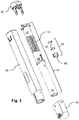
- Fig 1 shows a training device 10, which is preferably designed to resemble a real medicament delivery device for which the user needs training.
- the training device 10 is elongated along an axis L.
- the training device 10 comprises a dummy housing 20, a distal end cap 30 and a proximal removable cap 40.
- the end cap 30 is fixedly attached to the housing 20, but it is conceivable that end cap 30 may instead be replaced by a movable dummy activation button, should the training device be designed to mimic a medicament delivery device having an activation button.
- the end cap 30 could also be integrated with the housing 20, but for manufacturing purposes, the end cap 30 is preferably an individual component that is fixedly attached to the housing 20 during assembly.
- Fig. 2 shows the training device 10 in a ready state, in which state the proximal cap 40 has been removed and the training device 10 is ready to be used.
- a dummy needle guard 53 protrudes proximally from the housing.
- Fig. 3 displays an exploded view of the training device 10.
- a unitary component 50 of a generally tubular shape, is arranged in the housing.
- the unitary component 50 comprises at its distal end a first element 52, and at its proximal end a second element 58.
- the first element 52 and the second element 58 are axially directly connected, but separated, by a resilient member 55 such that the first element 52 and the second element 58 are spring-biased away from each other.
- the first element 52, the second element 58 and the resilient member 55 could also be arranged as individual components, but a unitary component 50, comprising the three members, is preferred for manufacturing and assembly purposes since the component may be molded, and mounted in the housing 20 in one piece.
- the first element 52 and the second element 58 are movable in relation to each other.
- the relative mobility of the first element 52 and the second element 58 may mean that they are both movable relative to each other and relative to the housing 20.
- one of the elements may be movable relative to the housing, e.g. towards the other element, while the latter is fixed relative to the housing.
- the dummy needle guard 53 protrudes proximally from a proximal end of the housing 20.
- the first element 52 of the unitary component 50 is fixedly attached to the housing 20.
- the second element 58 of the unitary component 50 is axially movable towards the first component.
- the resilient member 55 is in a relaxed state. Movement of the second element 58 towards the first element 52 tensions the resilient member 55. The movement of the second element 58 towards the first element 52 therefore requires the application of a certain force to overcome a spring force of the resilient member 55. The force is applied by the user pushing the dummy needle guard 53 of the device against a training injection site.
- the first element 52 comprises an actuator 70 ( Fig. 4 ), and the second element 58 comprises an indication member 60.
- the actuator 70 is configured to mechanically interact with the indication member 60 as they come into contact with each other.
- the actuator 70 and the indication member 60 may be configured in a number of ways, as a skilled person sees fit.
- the actuator 70 may be fixedly attached to, or integrated with, the first element 52, and may be a longitudinally elongated member, such as a rod. In the exemplified embodiment the actuator 70 is a proximally directed rod.
- the indication member 60 may be fixedly attached to, or integrated with, the second element 58, and may comprise a holder 68 and a resiliently flexible member, such as a metal snap dome 65. In the embodiment shown in Figs 3-5 , the indication member comprises two metal snap domes 65.
- the holder 68 is configured to hold the metal snap dome, or domes, in a fixed position relative to the second element 58.
- Fig. 3 and 4 show the first element 52 as a distal part of the unitary member 50, and the second element 58 as a proximal part of the unitary member 50.
- the first and the second elements may switch positions, for instance such that the actuator 70 is distally directed towards the indication member 60.
- a metal snap dome is a dome-shaped metal plate. Upon application of a sufficient force to the dome 65, the dome will suddenly buckle to the shape of an inverted dome 65'. The sudden buckling will emit a click sound and a person applying the force to the dome will feel a tactile sensation as the dome buckles. Upon removal of the force, the metal snap dome 65 will resume its original shape.
- the actuator 70 and the indication member 60 are separated from each other by distance D ( Fig. 4 ).
- the actuator 70 is configured to apply a force to the indication member 60.
- the applied force causes the metal snap dome 65 to buckle, as described above, such that a feedback signal is generated for indicating to a user that a simulated mechanical function has occurred.
- the feedback signal indicates that the user has handled the training device correctly, and if the training device had been a real medicament delivery device, an automatic sequence would have been triggered to cause a needle penetration and/or a delivery of a dose of medicament.
- the feedback signal may be an audible and/or tactile signal, such as, but not limited to, a click or a slight impact.
- Fig. 5a shows a detailed view of the indication member 60, comprising the holder 68 and two metal snap domes 65 in an unbuckled state.
- Fig. 5b shows a detailed view of the indication member 60 of Fig. 5a , wherein a force has been applied to the metal snap domes 65, which force has caused the metal snap dome 65 to buckle into the shape of an inverted dome 65', i.e. to a buckled state.
- the resilient member 55 is configured to mimic the resilience of a mechanical function, or spring, of a real medicament delivery device. Furthermore, the resilience of the indication member 60 may be configured by selecting a suitable thickness of the metal snap dome 65, or by using one or more metal snap domes 65 in the holder 68.
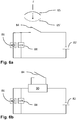
- the holder 68 of the indication member 60 may further be arranged with an electric circuit 80, an energy source 82, such as a battery, a switch 84, a speaker unit 86 and/or a piezoelectric unit 88.
- the electric circuit 80 may further comprise a control unit 90, having a clock function.
- the electric circuit 80 is conceptualized in Figs 6a and 6b .
- the buckling of the metal snap dome 65 causes the inverted dome 65' to close the switch 84 such that the electric circuit 80 is activated.
- the feedback signal may be an electronic sound, emitted by the speaker 86, and/or a vibration caused by the piezoelectric element 88 of the electric circuit 80.
- the electric circuit 80 may also comprise a control unit 90 having a clock function, which control unit may be activated by the switch 84.
- the control unit 90 measures the duration of a simulated dose delivery and compares it with a predetermined time value, and controls the feedback signal to indicate to the user the occurrence of a correct simulated dose delivery, or of a failed simulated dose delivery.
- the duration of the simulated dose delivery means the duration that the user presses the training device 10 against the training injection site such that the metal snap dome remains in the shape of the inverted dome 65'.
- the control unit 90 may activate a sound and/or a vibration for the duration of a simulated medicament dose delivery.
- the control unit 90 may further generate a negative signal if the training device 10 is removed from the simulated injection site before the duration of the simulated dose delivery has reached the predetermined time value, such as if the user removes the training device from the training injection site too early.
- the control unit 90 may further generate a positive signal if the training device 10 is pressed against the training injection site for a longer duration than the predetermined time value.
- the predetermined time value is the time it takes for the real medicament delivery device to deliver a dose.
- the speaker element 86 and the piezoelectric element 88 shown in Figs 6a and 6b should be regarded as complementary or optional elements. According to preference, either the speaker element 86 or the piezoelectric element 88, or both, may be comprised by the electric circuit.
- the training device 10 is supplied in the state shown in Fig. 1 .
- the user removes the cap 40 and pushes the training device, i.e. the projecting dummy needle guard 53, against a training injection site.
- the dummy needle guard 53 is a part of the second element 58 and the first element 52 is fixedly attached to the housing 20. Therefore, the second element 58 moves in relation to the housing 20, against the spring bias of the resilient member 55, towards the first element 52.
- metal snap dome 65 of the indication member 60 makes contact with the actuator 70.
- control unit 90 and its clock function may further control the feedback signal to maintain the signal for the duration of the simulated dose delivery, i.e. for the duration of the user pressing the device against the training injection site.
- the control unit 90 may also generate feedback signals to indicate to the user that the force and the training device 10 was applied for a sufficient time, or that the user removed the training device 10 too early.
- the user may remove the device from the training injection site, whereupon the second element 58 and the dummy needle guard 53 will return to the original position of the ready state, shown in Fig. 2 .
Abstract
A training device 10 for simulating a mechanical function of a medicament delivery device, which training device 10 comprises a dummy housing 20, a first element 52 comprising an actuator 70, a second element 58 comprising an indication member 60, and wherein a relative movement of the first element 52 towards the second element 58, which movement exceeds at least a distance D, causes the actuator 70 to interact with the indication member 60 such that a feedback signal is generated for indicating to a user that a simulated mechanical function has occurred.
Description
- The present device relates to a training device for simulating a mechanical function of a medicament delivery device. In more particular, the device indicates to a user that a simulated mechanical function has occurred.
- Medicament delivery devices such as auto-injectors provide allow users to handle medicament delivery in an easy, safe and reliable manner, without the need of a physician.
- An auto-injector currently on the market is disclosed in
WO2013032389 A1 . This document discloses an injection device comprising a housing and a container holder arranged within the housing. The container holder is configured to accommodate a medicament container having a needle attached to one end thereof and a stopper sealingly and slidably arranged inside the medicament container at the other end thereof. The injection device also has a first and a second energy accumulating member arranged in the interior of the housing and adapted to accumulate and store energy, a sleeve that is slidably arranged in relation to the housing, and a plunger holder arranged to be connected to the container holder. The plunger holder is operationally associated with the first energy accumulating member such that due to an output axial force from the first energy accumulating member, the plunger holder and the container holder are axially moveable in relation to the housing a predetermined distance towards the proximal end of the injection device from an initial position to a position following needle penetration. The injection device also includes a plunger rod being arranged with a proximal end thereof contactable with the stopper and slidably arranged in relation to the plunger holder and to the container holder. The plunger rod is operationally associated with the second energy accumulating member such that due to an output axial force from the second energy accumulating member the plunger rod is axially moveable in relation to the container holder towards the proximal end of the injection device from a locked position to a position following medicament injection, wherein, in the initial position of the plunger holder, movement of the plunger holder towards the proximal end of the injection device is substantially inhibited by at least one first biasable member interacting with the plunger holder, the first biasable member recoiling when being overlapped by an opening and/or recess of the sleeve such that the plunger holder is released. The injection device is in particular suitable for emergency applications such as adrenaline injections, as it has an auto-penetration and auto-injection functionality. - Before a user commences a drug administration programme by means of an auto-injector, it may be valuable for the user to undergo training to learn how to administer a drug properly by means of a particular auto-injector. A training device may be used for this purpose. Training is especially important for users of emergency devices, so that the user knows how to use it, and does not hesitate, when in a stressful situation.
- In view of the above, a general object of the present disclosure is to provide a training device for simulating a mechanical function of a medicament delivery device. Such a function may be a start of penetration and/or injection.
- In the present disclosure, when the term "distal" is used, this refers to the direction pointing away from the dose delivery site. When the term "distal part/end" is used, this refers to the part/end of the delivery device, or the parts/ends of the members thereof, which under use of the medicament delivery device is/are located furthest away from the dose delivery site. Correspondingly, when the term "proximal" is used, this refers to the direction pointing to the dose delivery site. When the term "proximal part/end" is used, this refers to the part/end of the delivery device, or the parts/ends of the members thereof, which under use of the medicament delivery device is/are located closest to the dose delivery site.
- Further, the term "longitudinal", with or without "axis", refers to a direction or an axis through the device or components thereof in the direction of the longest extension of the device or the component.
- The term "lateral", with or without "axis", refers to a direction or an axis through the device or components thereof in the direction of the broadest extension of the device or the component. "Lateral" may also refer to a position to the side of a "longitudinally" elongated body.
- In a similar manner, the terms "radial" or "transversal", with or without "axis", refers to a direction or an axis through the device or components thereof in a direction generally perpendicular to the longitudinal direction, e.g. "radially outward" would refer to a direction pointing away from the longitudinal axis.
- Also, if nothing else is stated, in the following description wherein the mechanical structure of the device and the mechanical interconnection of its components is described, the device is in an initial non-activated or non-operated state.
- According to a main aspect of the present disclosure there is provided a training device for simulating a mechanical function of a medicament delivery device, which training device comprises a dummy housing, a first element comprising an actuator, and a second element comprising an indication member wherein a relative movement of the first element towards the second element, which movement exceeds at least a distance D, causes the actuator to interact with the indication member such that a feedback signal is generated for indicating to a user that a simulated mechanical function has occurred.
- Advantageously, the dummy housing resembles the actual device for which the user needs training. The first element and the second element are movable relative to each other. One element may resemble a needle guard, movable in relation to the housing and in relation to the other element, and the other element may be arranged inside the housing, or may resemble an activation button protruding through the housing. The user may then simulate a medicament delivery by pressing the needle guard against a delivery site. The element resembling the needle guard may then move the distance D and thereby cause an interaction between the actuator and the indication element such that the feedback signal is generated. Alternatively, the first and the second element may both move, such as if the one of the elements resembles a needle guard, and the other element resembles a button, so that the sum of the distances moved by both elements towards each other exceeds the distance D.
- According to another aspect of the present disclosure, the feedback signal is an audible and/or tactile signal.
- In order to mimic an activation of a function, an audible and/or tactile signal is generated. For instance, the movement of a container and its needle during an auto-penetration step may often be both heard and felt in a real delivery device. Therefore, the generated signal of the training device should preferably be similar to the real device.
- According to another aspect of the present disclosure, the first element and the second element are integrated in a unitary component and wherein the unitary component comprises a resilient member which separates the first element and the second element such that the first element and the second element are spring-biased away from each other.
- Training devices are preferably inexpensive devices that are offered for free, or sold at low prices, to users of medicament delivery devices. To lower manufacturing costs, and to simplify assembly, the unitary component may be molded to comprise the first and second elements, as well as a resilient member to spring-bias the elements away from each other.
- Alternatively, the first and second elements may be stand-alone components that are assembled separately and wherein a spring is added to bias the elements away from each other.
- According to another aspect of the present disclosure, the actuator is a longitudinally elongated member.
- According to another aspect of the present disclosure, the actuator is a proximally directed pin.
- According to another aspect of the present disclosure, the actuator is fixedly attached to, or integrated with, the first element.
- In this manner, if the first element moves, the actuator moves together with the first element towards the second element for interacting with the indication member.
- According to another aspect of the present disclosure, the indication member comprises a resiliently flexible member.
- According to another aspect of the present disclosure, the indication member comprises a metal snap dome.
- The flexing of the indication member may cause a tactile or audible signal, and the metal snap dome in particular is known for this effect from the field of tactile metal switch contacts.
- According to another aspect of the present disclosure, the indication member is fixedly attached to, or integrated with, the second element.
- As such, if the second element moves, the indication member may move together with the second element towards the first element and its actuator.
- According to another aspect of the present disclosure, the indication member is arranged with an electric circuit, an energy source, a switch, a speaker unit and/or a piezoelectric unit, for generating the feedback signal.
- According to another aspect of the present disclosure, the electric circuit further comprises a control unit, having a clock function.
- According to another aspect of the present disclosure, the control unit measures the duration of a simulated dose delivery and compares it with a predetermined time value, and controls the feedback signal to indicate to the user the occurrence of a correct simulated dose delivery or a failed simulated dose delivery.
- To further improve the quality of the feedback given to the user, the electronic circuit may be arranged to not only indicate the start of needle penetration and/or dose delivery, but may also indicate to the user the time needed to press the training device against the training injection site.
- According to another aspect of the present disclosure, the second element is distally movable relative to the housing, against a spring bias, towards the first element.
- According to another aspect of the present disclosure, the second element comprises a dummy needle guard and the first element is fixed to the housing.
- Thus, the dummy needle guard extends proximally from a proximal end of the dummy housing. The first element is concealed inside the housing. In this case, the first element replaces the drive mechanism with which a real needle guard interacts in the medicament delivery device that is simulated.
- According to another aspect of the present disclosure, the simulated mechanical function is a start of needle penetration and/or a start of delivery of a dose of medicament, and/or a duration of a simulated dose delivery.
- For an emergency device, it is important for the user to know the steps that have to be completed to cause a dose delivery. Emergency delivery devices are normally highly automated. Therefore, the user has normally completed the necessary steps when the needle penetration and/or the dose delivery commences. The generated feedback signal will tell the user of the training device that the device has been handled correctly.
- According to an alternative aspect of the present disclosure, the actuator is a distally directed pin and the first element is distally movable, against a spring bias, towards the second element. The first element comprises a dummy needle guard and the second element is fixed to the housing.
- The actuator may be comprised by the first element, which may comprise the dummy needle guard.
- According to an alternative aspect of the present disclosure, the actuator is a distally directed pin and the second element is proximally movable, against a spring bias, towards the first element. The second element comprises a dummy activation button and the first element is fixed to the housing.
- This alternative aspect simulates a device which is only activated by a button, for instance a medicament delivery device that lacks a needle guard. Therefore, the indication member is movable with the dummy activation button.
- According to an alternative aspect of the present disclosure, the actuator is a proximally directed pin and the first element is proximally movable, against a spring bias, towards the second element. The first element comprises a dummy activation button and the second element is fixed to the housing.
- This alternative aspect simulates a device which is only activated by a button, for instance a medicament delivery device that lacks a needle guard. Therefore, the actuator is movable with the dummy activation button.
- According to an alternative aspect of the present disclosure, the actuator is a proximally directed pin and the first element is proximally movable and the second element is distally movable, the first and the second element being individually movable against a spring bias, towards each other. The first element comprises a dummy activation button and the second element comprises a dummy needle guard.
- In this way, the training device may simulate a medicament delivery device that requires movement of both the needle guard and a button to activate needle penetration and/or dose delivery. The proximally directed actuator pin moves with the dummy activation button and the indication member moves with the dummy needle guard.
- According to an alternative aspect of the present disclosure, the actuator is a distally directed pin and the first element is distally movable and the second element is proximally movable, the first and the second element being individually movable against a spring bias, towards each other. The first element comprises a dummy needle guard and the second element comprises a dummy activation button.
- In this way, the training device may simulate a medicament delivery device that requires movement of both the needle guard and a button to activate needle penetration and/or dose delivery. The distally directed actuator pin moves with the dummy needle guard and the indication member moves with the dummy activation button.
-
- Fig. 1
- a perspective view of a training device according to an embodiment of the present disclosure
- Fig. 2
- a perspective view of a ready state of the training device of
Fig. 1 - Fig. 3
- an exploded perspective view of the training device of
Fig. 1 - Fig. 4
- a cross-section view of a unitary component of the training device
- Fig. 5a-b
- perspective views of different states of the indication member of the training device
- Fig. 6a-b
- concepts of an electric circuit according to an alternative embodiment of the present disclosure
-
Fig 1 shows atraining device 10, which is preferably designed to resemble a real medicament delivery device for which the user needs training. Thetraining device 10 is elongated along an axis L. Thetraining device 10 comprises adummy housing 20, adistal end cap 30 and a proximalremovable cap 40. In the embodiment shown inFig. 1 , theend cap 30 is fixedly attached to thehousing 20, but it is conceivable thatend cap 30 may instead be replaced by a movable dummy activation button, should the training device be designed to mimic a medicament delivery device having an activation button. Theend cap 30 could also be integrated with thehousing 20, but for manufacturing purposes, theend cap 30 is preferably an individual component that is fixedly attached to thehousing 20 during assembly. -
Fig. 2 shows thetraining device 10 in a ready state, in which state theproximal cap 40 has been removed and thetraining device 10 is ready to be used. Adummy needle guard 53 protrudes proximally from the housing. -
Fig. 3 displays an exploded view of thetraining device 10. Aunitary component 50, of a generally tubular shape, is arranged in the housing. Theunitary component 50 comprises at its distal end afirst element 52, and at its proximal end asecond element 58. Thefirst element 52 and thesecond element 58 are axially directly connected, but separated, by aresilient member 55 such that thefirst element 52 and thesecond element 58 are spring-biased away from each other. - The
first element 52, thesecond element 58 and theresilient member 55 could also be arranged as individual components, but aunitary component 50, comprising the three members, is preferred for manufacturing and assembly purposes since the component may be molded, and mounted in thehousing 20 in one piece. - The
first element 52 and thesecond element 58 are movable in relation to each other. The relative mobility of thefirst element 52 and thesecond element 58 may mean that they are both movable relative to each other and relative to thehousing 20. In another embodiment, one of the elements may be movable relative to the housing, e.g. towards the other element, while the latter is fixed relative to the housing. - In the ready state shown in
Fig. 2 , thedummy needle guard 53 protrudes proximally from a proximal end of thehousing 20. Thefirst element 52 of theunitary component 50 is fixedly attached to thehousing 20. Thesecond element 58 of theunitary component 50 is axially movable towards the first component. In the ready state, theresilient member 55 is in a relaxed state. Movement of thesecond element 58 towards thefirst element 52 tensions theresilient member 55. The movement of thesecond element 58 towards thefirst element 52 therefore requires the application of a certain force to overcome a spring force of theresilient member 55. The force is applied by the user pushing thedummy needle guard 53 of the device against a training injection site. - The
first element 52 comprises an actuator 70 (Fig. 4 ), and thesecond element 58 comprises anindication member 60. Theactuator 70 is configured to mechanically interact with theindication member 60 as they come into contact with each other. Theactuator 70 and theindication member 60 may be configured in a number of ways, as a skilled person sees fit. Theactuator 70 may be fixedly attached to, or integrated with, thefirst element 52, and may be a longitudinally elongated member, such as a rod. In the exemplified embodiment theactuator 70 is a proximally directed rod. Theindication member 60 may be fixedly attached to, or integrated with, thesecond element 58, and may comprise aholder 68 and a resiliently flexible member, such as ametal snap dome 65. In the embodiment shown inFigs 3-5 , the indication member comprises two metal snap domes 65. Theholder 68 is configured to hold the metal snap dome, or domes, in a fixed position relative to thesecond element 58. -
Fig. 3 and4 show thefirst element 52 as a distal part of theunitary member 50, and thesecond element 58 as a proximal part of theunitary member 50. However, in alternative embodiments, the first and the second elements may switch positions, for instance such that theactuator 70 is distally directed towards theindication member 60. - A metal snap dome is a dome-shaped metal plate. Upon application of a sufficient force to the
dome 65, the dome will suddenly buckle to the shape of an inverted dome 65'. The sudden buckling will emit a click sound and a person applying the force to the dome will feel a tactile sensation as the dome buckles. Upon removal of the force, themetal snap dome 65 will resume its original shape. - In the ready state, the
actuator 70 and theindication member 60 are separated from each other by distance D (Fig. 4 ). When the relative movement of thefirst element 52 and thesecond element 58 toward each other equals or exceeds the distance D, theactuator 70 and theindication member 60 interact, by mechanical contact. Theactuator 70 is configured to apply a force to theindication member 60. The applied force causes themetal snap dome 65 to buckle, as described above, such that a feedback signal is generated for indicating to a user that a simulated mechanical function has occurred. The feedback signal indicates that the user has handled the training device correctly, and if the training device had been a real medicament delivery device, an automatic sequence would have been triggered to cause a needle penetration and/or a delivery of a dose of medicament. The feedback signal may be an audible and/or tactile signal, such as, but not limited to, a click or a slight impact. -
Fig. 5a shows a detailed view of theindication member 60, comprising theholder 68 and two metal snap domes 65 in an unbuckled state. -
Fig. 5b shows a detailed view of theindication member 60 ofFig. 5a , wherein a force has been applied to the metal snap domes 65, which force has caused themetal snap dome 65 to buckle into the shape of an inverted dome 65', i.e. to a buckled state. - The
resilient member 55 is configured to mimic the resilience of a mechanical function, or spring, of a real medicament delivery device. Furthermore, the resilience of theindication member 60 may be configured by selecting a suitable thickness of themetal snap dome 65, or by using one or more metal snap domes 65 in theholder 68. - In an alternative embodiment, the
holder 68 of theindication member 60 may further be arranged with an electric circuit 80, anenergy source 82, such as a battery, aswitch 84, aspeaker unit 86 and/or apiezoelectric unit 88. The electric circuit 80 may further comprise acontrol unit 90, having a clock function. The electric circuit 80 is conceptualized inFigs 6a and 6b . - In the alternative embodiment shown in
Fig 6a , the buckling of themetal snap dome 65 causes the inverted dome 65' to close theswitch 84 such that the electric circuit 80 is activated. The feedback signal may be an electronic sound, emitted by thespeaker 86, and/or a vibration caused by thepiezoelectric element 88 of the electric circuit 80. Alternatively, as shown inFig. 6b , the electric circuit 80 may also comprise acontrol unit 90 having a clock function, which control unit may be activated by theswitch 84. Thecontrol unit 90 measures the duration of a simulated dose delivery and compares it with a predetermined time value, and controls the feedback signal to indicate to the user the occurrence of a correct simulated dose delivery, or of a failed simulated dose delivery. The duration of the simulated dose delivery means the duration that the user presses thetraining device 10 against the training injection site such that the metal snap dome remains in the shape of the inverted dome 65'. Thecontrol unit 90 may activate a sound and/or a vibration for the duration of a simulated medicament dose delivery. Thecontrol unit 90 may further generate a negative signal if thetraining device 10 is removed from the simulated injection site before the duration of the simulated dose delivery has reached the predetermined time value, such as if the user removes the training device from the training injection site too early. Thecontrol unit 90 may further generate a positive signal if thetraining device 10 is pressed against the training injection site for a longer duration than the predetermined time value. The predetermined time value is the time it takes for the real medicament delivery device to deliver a dose. - The
speaker element 86 and thepiezoelectric element 88 shown inFigs 6a and 6b should be regarded as complementary or optional elements. According to preference, either thespeaker element 86 or thepiezoelectric element 88, or both, may be comprised by the electric circuit. - In use, the
training device 10 is supplied in the state shown inFig. 1 . The user removes thecap 40 and pushes the training device, i.e. the projectingdummy needle guard 53, against a training injection site. In the exemplified embodiment, thedummy needle guard 53 is a part of thesecond element 58 and thefirst element 52 is fixedly attached to thehousing 20. Therefore, thesecond element 58 moves in relation to thehousing 20, against the spring bias of theresilient member 55, towards thefirst element 52. When the second element has moved the distance D,metal snap dome 65 of theindication member 60 makes contact with theactuator 70. If the user applies enough force, which force is calculated to match the force required for the corresponding real medicament delivery device, themetal snap dome 65 will buckle and emit an audible sound and/or a tactile sensation. In the case of the alternative embodiment described above, thecontrol unit 90 and its clock function may further control the feedback signal to maintain the signal for the duration of the simulated dose delivery, i.e. for the duration of the user pressing the device against the training injection site. Thecontrol unit 90 may also generate feedback signals to indicate to the user that the force and thetraining device 10 was applied for a sufficient time, or that the user removed thetraining device 10 too early. - After the simulated dose delivery, the user may remove the device from the training injection site, whereupon the
second element 58 and thedummy needle guard 53 will return to the original position of the ready state, shown inFig. 2 .
Claims (15)
- A training device 10 for simulating a mechanical function of a medicament delivery device, which training device 10 comprises- a dummy housing 20- a first element 52 comprising an actuator 70;- a second element 58 comprising an indication member 60;wherein a relative movement of the first element 52 towards the second element 58, which movement exceeds at least a distance D, causes the actuator 70 to interact with the indication member 60 such that a feedback signal is generated for indicating to a user that a simulated mechanical function has occurred.
- A training device for a medicament delivery device according to claim 1, wherein the feedback signal is an audible and/or tactile signal.
- A training device for a medicament delivery device according to claim 2, wherein the first element 52 and the second element 58 are integrated in a unitary component 50 and wherein the unitary component 50 comprises a resilient member 55 which separates the first element 52 and the second element 58 such that the first element 52 and the second element 58 are spring-biased away from each other.
- A training device for a medicament delivery device according to claim 1, wherein the actuator 70 is a longitudinally elongated member.
- A training device for a medicament delivery device according to claim 4, wherein the actuator 70 is a proximally directed rod.
- A training device for a medicament delivery device according to claim 4, wherein the actuator 70 is fixedly attached to, or integrated with, the first element 52.
- A training device for a medicament delivery device according to claim 1, wherein the indication member 60 comprises a resiliently flexible member.
- A training device for a medicament delivery device according to claim 7, wherein the resiliently flexible member is a metal snap dome 65.
- A training device for a medicament delivery device according to claim 7, wherein the indication member 60 is fixedly attached to, or integrated with, the second element 58.
- A training device for a medicament delivery device according to claim 1, wherein the indication member 60 is arranged with an electric circuit 80, an energy source 82, a switch 84, a speaker unit 86 and/or a piezoelectric unit 88, for generating the feedback signal.
- A training device for a medicament delivery device according to claim 10, wherein the electric circuit 80 further comprises a control unit 90, having a clock function.
- A training device for a medicament delivery device according to claim 10, wherein the control unit 90 measures a duration of a simulated dose delivery and compares it with a predetermined time value, and controls the feedback signal to indicate to the user the occurrence of a correct simulated dose delivery, or of a failed simulated dose delivery.
- A training device for a medicament delivery device according to any of the claims 5-7, wherein the second element 58 is distally movable relative to the housing, against a spring bias, towards the first element 52.
- A training device for a medicament delivery device according to claim 12, wherein the second element 58 comprises a dummy needle guard 53 and the first element 52 is fixed to the housing.
- A training device for a medicament delivery device according to claim 1, wherein the simulated mechanical function is a start of needle penetration and/or a start of delivery of a dose of medicament and/or a duration of a simulated dose delivery.
Priority Applications (6)
| Application Number | Priority Date | Filing Date | Title |
|---|---|---|---|
| EP16202610.8A EP3333832A1 (en) | 2016-12-07 | 2016-12-07 | Training device |
| EP17797652.9A EP3552197A1 (en) | 2016-12-07 | 2017-11-14 | Training device |
| PCT/EP2017/079206 WO2018104011A1 (en) | 2016-12-07 | 2017-11-14 | Training device |
| US16/467,648 US11475795B2 (en) | 2016-12-07 | 2017-11-14 | Training device |
| CN201780074480.8A CN110036432A (en) | 2016-12-07 | 2017-11-14 | Training device |
| TW106140505A TW201828267A (en) | 2016-12-07 | 2017-11-22 | Training device |
Applications Claiming Priority (1)
| Application Number | Priority Date | Filing Date | Title |
|---|---|---|---|
| EP16202610.8A EP3333832A1 (en) | 2016-12-07 | 2016-12-07 | Training device |
Publications (1)
| Publication Number | Publication Date |
|---|---|
| EP3333832A1 true EP3333832A1 (en) | 2018-06-13 |
Family
ID=57542760
Family Applications (2)
| Application Number | Title | Priority Date | Filing Date |
|---|---|---|---|
| EP16202610.8A Withdrawn EP3333832A1 (en) | 2016-12-07 | 2016-12-07 | Training device |
| EP17797652.9A Pending EP3552197A1 (en) | 2016-12-07 | 2017-11-14 | Training device |
Family Applications After (1)
| Application Number | Title | Priority Date | Filing Date |
|---|---|---|---|
| EP17797652.9A Pending EP3552197A1 (en) | 2016-12-07 | 2017-11-14 | Training device |
Country Status (5)
| Country | Link |
|---|---|
| US (1) | US11475795B2 (en) |
| EP (2) | EP3333832A1 (en) |
| CN (1) | CN110036432A (en) |
| TW (1) | TW201828267A (en) |
| WO (1) | WO2018104011A1 (en) |
Citations (9)
| Publication number | Priority date | Publication date | Assignee | Title |
|---|---|---|---|---|
| US4640686A (en) * | 1986-02-24 | 1987-02-03 | Survival Technology, Inc. | Audible signal autoinjector training device |
| US20070111175A1 (en) * | 2005-11-03 | 2007-05-17 | Raven Sophie R | Training device for an automatic injector |
| US20080059133A1 (en) * | 2005-02-01 | 2008-03-06 | Edwards Eric S | Medical injector simulation device |
| WO2013032389A1 (en) | 2011-08-31 | 2013-03-07 | Shl Group Ab | Injection device |
| WO2013130973A1 (en) * | 2012-03-02 | 2013-09-06 | Abbvie Inc. | Automatic injection training device |
| WO2014056868A1 (en) * | 2012-10-11 | 2014-04-17 | Carebay Europe Ltd | Automatic injection training device |
| WO2014139914A1 (en) * | 2013-03-13 | 2014-09-18 | Sanofi-Aventis Deutschland Gmbh | Assembly for a drug delivery device comprising a feedback feature |
| CH709126A2 (en) * | 2015-05-07 | 2015-07-15 | Tecpharma Licensing Ag | Training device for a user to use an auto-injector training. |
| WO2016078870A1 (en) * | 2014-11-20 | 2016-05-26 | Carebay Europe Ltd | Automatic injection training device |
Family Cites Families (9)
| Publication number | Priority date | Publication date | Assignee | Title |
|---|---|---|---|---|
| CN101198366A (en) * | 2005-06-16 | 2008-06-11 | 诺和诺德公司 | Method and apparatus for assisting patients in self administration of medication |
| US8021344B2 (en) * | 2008-07-28 | 2011-09-20 | Intelliject, Inc. | Medicament delivery device configured to produce an audible output |
| BR112013033500A2 (en) * | 2011-06-28 | 2017-01-24 | Alk Ag | computer program method, device and product for training the use of an autoinjector |
| CN103648552B (en) * | 2011-07-15 | 2016-08-31 | 赛诺菲-安万特德国有限公司 | drug delivery device with electromechanical drive mechanism |
| WO2013107723A1 (en) * | 2012-01-16 | 2013-07-25 | Sanofi-Aventis Deutschland Gmbh | Blinding kit for clinical trials |
| US10748449B2 (en) * | 2012-04-04 | 2020-08-18 | Noble International, Inc. | Medicament delivery training device |
| US9541491B2 (en) * | 2012-04-18 | 2017-01-10 | Phillip Nelson Rounds | Test methods and device for measuring transient resistance to movement |
| CN102646355B (en) * | 2012-04-28 | 2014-01-22 | 徐州医学院 | Digital anesthesia operation teaching model |
| AU2015208397B2 (en) * | 2014-01-21 | 2017-08-10 | Shl Medical Ag | Injector training device |
-
2016
- 2016-12-07 EP EP16202610.8A patent/EP3333832A1/en not_active Withdrawn
-
2017
- 2017-11-14 EP EP17797652.9A patent/EP3552197A1/en active Pending
- 2017-11-14 WO PCT/EP2017/079206 patent/WO2018104011A1/en unknown
- 2017-11-14 US US16/467,648 patent/US11475795B2/en active Active
- 2017-11-14 CN CN201780074480.8A patent/CN110036432A/en active Pending
- 2017-11-22 TW TW106140505A patent/TW201828267A/en unknown
Patent Citations (9)
| Publication number | Priority date | Publication date | Assignee | Title |
|---|---|---|---|---|
| US4640686A (en) * | 1986-02-24 | 1987-02-03 | Survival Technology, Inc. | Audible signal autoinjector training device |
| US20080059133A1 (en) * | 2005-02-01 | 2008-03-06 | Edwards Eric S | Medical injector simulation device |
| US20070111175A1 (en) * | 2005-11-03 | 2007-05-17 | Raven Sophie R | Training device for an automatic injector |
| WO2013032389A1 (en) | 2011-08-31 | 2013-03-07 | Shl Group Ab | Injection device |
| WO2013130973A1 (en) * | 2012-03-02 | 2013-09-06 | Abbvie Inc. | Automatic injection training device |
| WO2014056868A1 (en) * | 2012-10-11 | 2014-04-17 | Carebay Europe Ltd | Automatic injection training device |
| WO2014139914A1 (en) * | 2013-03-13 | 2014-09-18 | Sanofi-Aventis Deutschland Gmbh | Assembly for a drug delivery device comprising a feedback feature |
| WO2016078870A1 (en) * | 2014-11-20 | 2016-05-26 | Carebay Europe Ltd | Automatic injection training device |
| CH709126A2 (en) * | 2015-05-07 | 2015-07-15 | Tecpharma Licensing Ag | Training device for a user to use an auto-injector training. |
Also Published As
| Publication number | Publication date |
|---|---|
| WO2018104011A1 (en) | 2018-06-14 |
| EP3552197A1 (en) | 2019-10-16 |
| US20190362652A1 (en) | 2019-11-28 |
| US11475795B2 (en) | 2022-10-18 |
| TW201828267A (en) | 2018-08-01 |
| CN110036432A (en) | 2019-07-19 |
Similar Documents
| Publication | Publication Date | Title |
|---|---|---|
| DK2820640T3 (en) | AUTOMATIC INJECTION TRAINING DEVICE | |
| US8622973B2 (en) | Simulated medicament delivery device configured to produce an audible output | |
| US4640686A (en) | Audible signal autoinjector training device | |
| US10576213B2 (en) | Autoinjector with delayed signal of complete medication delivery | |
| JP2016528983A (en) | Injection device | |
| CN108136131B (en) | Medicament delivery device | |
| ATE445429T1 (en) | INJECTION DEVICE WITH INTERNAL DOSE INDICATOR | |
| US20140276568A1 (en) | Systems and methods for dampening friction in an autoinjector device | |
| US20150100024A1 (en) | Medicament delivery and training cartridge system and mechanisms of actuation | |
| JP6434413B2 (en) | Drug delivery device with trigger button | |
| US11475795B2 (en) | Training device | |
| KR102214019B1 (en) | Auxiliary device for drug delivery devices | |
| US20220215779A1 (en) | Drive mechanism for a medicament delivery training device | |
| EP4134111A1 (en) | Autoinjector and actuating assembly thereof | |
| WO2023238104A1 (en) | Autoinjector kits | |
| CA2940544A1 (en) | Auto-injector | |
| AU2015275341A1 (en) | Automatic injection training device |
Legal Events
| Date | Code | Title | Description |
|---|---|---|---|
| PUAI | Public reference made under article 153(3) epc to a published international application that has entered the european phase |
Free format text: ORIGINAL CODE: 0009012 |
|
| AK | Designated contracting states |
Kind code of ref document: A1 Designated state(s): AL AT BE BG CH CY CZ DE DK EE ES FI FR GB GR HR HU IE IS IT LI LT LU LV MC MK MT NL NO PL PT RO RS SE SI SK SM TR |
|
| AX | Request for extension of the european patent |
Extension state: BA ME |
|
| STAA | Information on the status of an ep patent application or granted ep patent |
Free format text: STATUS: THE APPLICATION HAS BEEN WITHDRAWN |
|
| 18W | Application withdrawn |
Effective date: 20180803 |