EP3879979B1 - Vorrichtung und verfahren zum einfrieren einer biologischen lösung - Google Patents
Vorrichtung und verfahren zum einfrieren einer biologischen lösung Download PDFInfo
- Publication number
- EP3879979B1 EP3879979B1 EP19823995.6A EP19823995A EP3879979B1 EP 3879979 B1 EP3879979 B1 EP 3879979B1 EP 19823995 A EP19823995 A EP 19823995A EP 3879979 B1 EP3879979 B1 EP 3879979B1
- Authority
- EP
- European Patent Office
- Prior art keywords
- heat transfer
- transfer surface
- container
- holder
- freezing
- Prior art date
- Legal status (The legal status is an assumption and is not a legal conclusion. Google has not performed a legal analysis and makes no representation as to the accuracy of the status listed.)
- Active
Links
Images


Classifications
-
- A—HUMAN NECESSITIES
- A01—AGRICULTURE; FORESTRY; ANIMAL HUSBANDRY; HUNTING; TRAPPING; FISHING
- A01N—PRESERVATION OF BODIES OF HUMANS OR ANIMALS OR PLANTS OR PARTS THEREOF; BIOCIDES, e.g. AS DISINFECTANTS, AS PESTICIDES OR AS HERBICIDES; PEST REPELLANTS OR ATTRACTANTS; PLANT GROWTH REGULATORS
- A01N1/00—Preservation of bodies of humans or animals, or parts thereof
- A01N1/10—Preservation of living parts
- A01N1/14—Mechanical aspects of preservation; Apparatus or containers therefor
- A01N1/142—Apparatus
- A01N1/144—Apparatus for temperature control, e.g. refrigerators or freeze-drying apparatus
- A01N1/145—Stationary or portable vessels generating cryogenic temperatures, e.g. liquid nitrogen baths
-
- A—HUMAN NECESSITIES
- A01—AGRICULTURE; FORESTRY; ANIMAL HUSBANDRY; HUNTING; TRAPPING; FISHING
- A01N—PRESERVATION OF BODIES OF HUMANS OR ANIMALS OR PLANTS OR PARTS THEREOF; BIOCIDES, e.g. AS DISINFECTANTS, AS PESTICIDES OR AS HERBICIDES; PEST REPELLANTS OR ATTRACTANTS; PLANT GROWTH REGULATORS
- A01N1/00—Preservation of bodies of humans or animals, or parts thereof
- A01N1/10—Preservation of living parts
- A01N1/16—Physical preservation processes
- A01N1/162—Temperature processes, e.g. following predefined temperature changes over time
Definitions
- This disclosure relates, in general to a device and a method for freezing liquid mixtures or suspensions containing sensitive substances, such as biological materials in multiple small-volume containers, in particular wherein the biological materials are living cells, blood cells, viruses, proteins, antibodies, among others. Furthermore, this disclosure improves the reproducibility of nucleation and crystal growth during freezing of small volumes of aqueous mixtures in multiple containers.
- Cryopreservation of sensitive substances is essential for many applications, with relevance for the exploitation of cellular biology.
- Cells or derivatives resulting from its culture are generally cryopreserved for management of production and distribution, including banking for preservation of their genetic material.
- Cryopreservation involves different processes, such as addition of cryoprotective substances, cooling (freezing), heating (thawing), mixing, which are determining of the physical-chemical stability of the biological products. Since cryopreservation involves a sequence of processes, inconsistency is likely to propagate and amplify from the earliest (such as cooling and freezing) to the latest (such as thawing and mixing). Therefore, maximizing freezing consistency is crucial to maximize the overall preservation of the biological products.
- Natural convection is a major cause for the heterogeneity in solutes distribution (cryoconcentration or freeze-concentration) that occurs in frozen solutions of biologics. It has been shown that density-gradient-driven convection is critical, because it displaces the solutes towards the bottom and center of cylindrical containers. The formation of ice dendrites, by using a nonconvective freezing geometry, i.e., by freezing unidirectionally from bottom to top, has been reported to attenuate natural convection thus preventing cryoconcentration [1,2].
- cryopreservation Another critical aspect for cryopreservation is the control of ice nucleation temperature and site.
- aqueous solutions tend to cool to a temperature below their melting point before ice nucleation occurs, a condition known as supercooling. This has been described to have a compromising effect on cell viability after thawing and therefore in the whole process of cryopreservation.
- supercooling several techniques to control ice nucleation have been proposed. Like the introduction of a small ice crystal or heterogeneous nucleators of ice into the sample; by manually generating a cold spot on the outside of the cryocontainer; by electrofreezing; by mechanical methods (shaking, application of ultrasound); by shock cooling or by pressure shift [3].
- the approach followed in this disclosure relates to enhancing nucleation by fast cooling of the container's base.
- the container's heat resistance through the bottom must be minimized. This can be achieved by using a conductive material, such as a liquid with lower freezing point than water, polymer, paste or sticker, that improves the contact between the heat transfer plate and the bottom of the container, i.e. that minimizes the air within both surfaces. Rosa et al.
- the fast cooling of the base required to enhance nucleation at the bottom, can cause the complete uncontrolled freezing of the sample instead of nucleation only.
- thermal inertia may govern the dynamic of the freezing process.
- the fraction of liquid that freezes during nucleation should not be higher than 20% assuring, preferably lower than 10%, that most of sample freezes at a controlled rate under the bottom-up direction. Therefore, cooling at the bottom should be intense and brief, to enable nucleation of the solution while minoring the layer of volume that freezes uncontrolled, under supercooled conditions. This can be achieved by implementing a sharp cooling of the container's base to a considerably low temperature (typically lower than -40 °C), for example by placing the containers on top of a cold surface.
- two criteria are critical a) that all containers are placed on a previously cooled heat transfer surface at the same time and b) that the contact between the bottom of the containers and the heat transfer surface is equivalent, regardless of roughness variations. Roughness variations are likely to cause larger inconsistency as the bottom area of the containers becomes smaller.
- the aspect ratio height/width is not smaller than 1, to minimize the height of liquid that supercools by thermal diffusion before the nucleation event, thus minoring the volume of sample than freezes uncontrolled.
- containers for unidirectional freezing may have a small area at the bottom, which may complicate heat transfer consistency due to typical roughness variations, for example in volumes smaller than a 2 ml.
- nucleus implies the formation of an interface at the boundaries of a new phase. Liquids cooled below the maximum heterogeneous nucleation temperature (melting temperature), but which are above the homogeneous nucleation temperature (pure substance freezing temperature) are called supercooled.
- the present disclosure aims at solving the above-mentioned problems.
- DE 10 2008 048 709 A1 discloses a device for cryopreserving biological material such as cells or tissues.
- the device comprises one or more heat transfer means that can be pressed against a container by means of e.g. springs.
- a single heat transfer means is provided on the bottom side.
- unidirectional geometry means the creation of a unidirectional temperature gradient along an axis that causes the ice-front to develop and progress along the chosen axis.
- unidirectional bottom-up geometry means the creation of a unidirectional temperature gradient along the vertical axis that causes the ice-front to develop and progress from bottom to top.
- controlled nucleation refers to formation of the first ice crystals within a short time interval, preferentially less than a minute, after the containers contact with the heat transfer surface. It happens specifically in the bottom surface of the containers and the fraction of liquid that freezes immediately upon nucleation (due to local supercooling) should not be higher than 20%.
- the present invention provides a method as defined in claim 1.
- Particular embodiments are defined in the dependent claims.
- the freezing is unidirectional from the bottom of the container to the top. Due to the isolation of the holder with a low heat conductivity material, the freezing is achieved in a controlled manner and one of the advantages of the present disclosure when compared to other similar technologies is that the freezing is not radial. For this reason, the freezing of the content of the vial is controlled, homogeneous, and more effective, irrespective of the total volume of the sample.
- the freezing is homogeneous between vials of the same freezing cycle. This means that the content of each vial is uniformly frozen and frozen in the same way as the other vials of the same freezing cycle. Additionally, the freezing efficacy is high weather the vial contains 1 ⁇ l of solution or 100 ml of solution.
- the present invention relates to a device for freezing a biological solution as defined in claim 7.
- a device for freezing a biological solution as defined in claim 7.
- Particular embodiments are defined in the dependent claims.
- the pressing means (103) may comprise a compressor (108) for countering the holder (102), such that an even-distributed pressure is applied on the holder (102), preferably wherein a manual or a mechanical even-distributed pressure is applied on the holder (102).
- the holder (102) is made of a low heat conductivity material, preferably and to obtain even better results the low heat conductivity material is plastics, ceramics or a composite.
- the device comprises at least one container (109).
- the pressing means are configurated for: placing a portion of the container (123) in contact with the heat transfer surface (101), transferring heat from the heat transfer surface (101) to the portion of the container (123), removing the container (109) away from the heat transfer surface (101) and replacing the portion of the container (123) in contact with the heat transfer surface (101), preferably wherein the portion of the container is the bottom of the container.
- the holder (102) comprises compressible means (102a, 102b, 102c) selected from a spring (118), a tab (120) or a pin (212), such that the holder (102) is compressible between a first position and a second position, wherein the first position places the bottom of the container (123) in contact with the heat transfer surface (101) and the second position places the bottom of the container (123) away from the heat transfer surface (101).
- the holder (102) may be pressed against a flat configuration (101a) of the heat transfer surface (101).
- the holder (102) may be pressed against a recess configuration (101b) of the heat transfer surface (101), preferably wherein the recess (117) of the heat transfer surface (101b) is a depression with a depth comprised between 0.5-3 mm.
- the heat transfer surface (101) may be a channel (116) for removing an excess of liquid, preferably for removing an excess of a contact promoting material.
- the channel (116) may have a depth of 0.5-3 mm, and a width from 1-5 mm.
- the device may further comprise a pressing means frame (104), wherein the pressing means frame (104) comprises a hinge (106) and a handler (105).
- the heat transfer surface (101) may be made of a conductive material selected from stainless steel, copper, aluminium, or mixtures thereof.
- the device may further comprise a coolant reservoir (113) for storing the cooling agent.
- the device may further comprise an insulation frame (111) for insulating the heat transfer surface from the room temperature and for protecting the user.
- the device may further comprise a fin supporter (112) for attaining a uniform heat exchange.
- the device may further comprise fins (115) for providing a larger contact area with a cooling agent.
- the device may further comprise a contact layer (119) for removing the residual air between the heat transfer surface (101) and the container (109), preferably wherein the contact layer (119) is a liquid, a paste, a paper or a sticker, preferably wherein the contact layer (119) has a height from 0.1 mm - 3 mm.
- the container (109) may have an height from 5-50 mm and a diameter from 4-10 mm.
- the container may have an aspect ratio height/width higher than 1.
- container wall (122) may have a thickness from 0.4-2 mm, and the container bottom (123) has a thickness from 0.2-2 mm.
- the container wall (122) and the bottom of the container (123) are made of different materials.
- the container wall (122) is made of polymers, ceramics, glass or other low heat conductive materials.
- the bottom of the container (123) is made of high conductivity materials such as stainless steel, aluminium or others, or build using low conductive materials such as polymers, glass or others.
- the device is a freezing device.
- the present disclosure also relates to a method for operating the device, not forming part of the present invention and comprising the following steps:
- said controlled freezing rate of the biological solution within said container may be from 0.1 °C/min - 100.0 °C/min, preferably 0.5 °C/min - 10 °C/min, more preferably 1 °C/min - 5 °C/min.
- the step of pre-cooling the device may be carried out at a temperature lower than -20°C, preferably lower than -30 °C, more preferably lower than -40 °C.
- the step of removing the container (109) from the heat transfer surface (101) may be carried out by placing the container (109) away from the heat transfer surface (101), preferably by an air gap from 0.1mm up to 15mm, while maintaining a biological solution at a temperature near 0°C.
- the step of re-contacting the container (109) with the heat transfer surface (101) may be carried out by placing the container (109) in contact with the heat transfer surface (101) by pressing the holder (102) against the heat transfer surface (101).
- the biological solution may comprise a: microorganism, tissue, live cell, stem cell, primary cell, cell line, live or attenuated virus, nucleic acid, monoclonal antibody, polyclonal antibody, biomolecule, non-peptide analogue, peptide, protein, RNA, DNA, oligonucleotide, viral particle, or mixtures thereof.
- the method for bottom up geometry freezing and/or nucleation of a sample solution comprises the following steps:
- the method comprises a plurality of containers.
- the controlled freezing rate of the biological solution within said container is from 0.1 °C/min - 100.0 °C/min, preferably 0.5 °C/min - 10 °C/min, more preferably 1 °C/min - 5 °C/min.
- the step of pre-cooling the device is carried out at a temperature lower than -20 °C, preferably lower than - 30 °C, more preferably lower than -40 °C.
- the step of interrupting the contact between the container and the heat transfer surface is carried out by placing the container away from the heat transfer surface, preferably by an air gap from 0.1mm up to 15 mm, while maintaining a biological solution at a temperature near 0 °C.
- the step of contacting the container with the heat transfer surface at a predefined freezing rate is carried out by placing the container in contact with the heat transfer surface by pressing the holder against the heat transfer surface.
- cryopreservation of sensitive substances such as biological materials and solutions
- inconsistency associated to the freezing and thawing phenomena.
- Many variables contribute to freezing inconsistency, with the two major issues related to natural convection and ice nucleation.
- a method to enable unidirectional bottom-up freezing in a batch of small-volume containers including the following steps: pre-cooling the heat transfer surface to a low temperature (for example lower than -40 °C); setting multiple containers in a holder and contacting all the containers simultaneously with the cold surface by pressing the holder towards the heat transfer surface, using an intermediate contact promoting material (such as a liquid or a polymer), to enable control nucleation; after nucleation of a minor layer of volume, setting the holder and the containers to a position separated from the cold surface; finally pressing the holder against the cold surface while controlling the ice growth rate in unidirectional bottom-up geometry.
- a low temperature for example lower than -40 °C
- the device of freezing a biological solution wherein the biological solution is a liquid biological solution or a suspension, herein described to attain the previously described method, comprises a driver that forces the containers with down force to meet the heat transfer surface on a lock down position.
- the nucleation process starts when the containers are pressed against the heat transfer surface, all at the same time, using an intermediate contact promoting material to assue that the fraction of liquid that freezes during nucleation is not be higher than 20% of the total volume.
- the driver is set to the lock up position, and the containers stand in a standby position separated from the heat transfer surface by a air gap that go from 0.1 mm up to 15 mm, while mantaining the biological solution near 0 °C.
- the driver is pressed down again to promote the contact of the bottom of the containers with the heat transfer surface and is applied the chosen freezing rate, by cooling the heat transfer surface typically from 0.1 °C /min to 100 °C/min depending of the thermal sensitivity of the biological material.
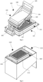
- the device of freezing biological solutions herein described to attain the previously described method comprises the following elements: a freezing head (100) which includes a heat transfer surface (101), may include a holder (102) with receiving cavities in which containers (109) are fit, and may also include pressing means (103).
- the freezing altar is connected to a system (114) apparatus which can be represented in different configurations and use several cooling agents and or other known cooling systems.
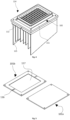
- the apparatus of the freezing head plus the cold system can be presented in a configuration of involvement by a container and or insulations such as the example on Fig. 3 .
- FIG. 1 In an embodiment, which is represented from figures 1 to 9 , which are not intended to limit the object of the present application, is shown a device for preserving, by process of freezing and/or thawing, storage and transportation of biological materials.
- the containers (109) will hold the biological samples during the freezing, thawing, store and transportation of these. They are specially build using biological safe materials to maintain the samples safe during all the process.
- the containers (109) are designed accordingly to fit the holder (102) cavities, different volume samples and different thermal processes desired.
- the container (109) specifications, are taken in account to a specific whole process of thermal exchange.
- the containers (109) can have an height from 5 mm to 50 mm and a diameter from 4 mm to 10 mm, with an aspect raio (height/width) higher than 1.
- the container wall (122) might have a thickness from 0.4 mm to 2 mm, and the container bottom (123) can differ the thickness from 0.2 mm to 2 mm.
- the container wall (122) and the container bottom (123) may be of different materials.
- the container wall (122) can be built of polymers, ceramics, glass or other low heat conductive materials in order to keep the low conductivitie on the lateral surface from the container (109).
- the container bottom (123) can be built using high conductivity materials such as stainless steel, aluminium or others, or build using low conductive materials such as polymers, glass or others.
- the bottom of the container (109), depending on the thermal dynamic figured for a specific heat exchange method employed, may have low or high transfer coefficient. The diference from the materials can be handy to obtain vertical driven heat flux gradients withouth significant influence from the container wall (122), specially, when freezing with small volume samples, since the mass ratio from the container (109) compared to the sample volume is significant.
- the cold system (114) is represented by the freezing head (100) and other elements that will allow controlling the temperature on the heat transfer surface (101), and containers (109).
- the integrative parts can be any electronics, mechanical or machined used to create a controlled driven heat flux through the cold system (114).
- Fig. 4 is represented an example of a cold system setup. Fins (115) will transfer the heat between the cooling agent that can be dry ice, liquid nitrogen or other.
- the cooling agents are stored on the coolant reservoir (113).
- the fin supporter (112) is directly attached to the fins (115) and will help to avoid temperature fluctuations when the containers (109) and holder (102) are put in contact with the heat transfer surface (101).
- the inertia from the heat transfer surface (101) will freeze a small layer of the sample, less than 20% of the total volume, inside the containers (109) while also the heat transfer surface (101) rises the temperature during the heat exchange. Since the temperature from the heat transfer surface (101) rose to a higher temperature during the formation of the first ice layer on the containers (109), the ice growth will become now slower and controlled by the fin supporter (112) temperature.
- the freezing head (100) which always include a horizontal plate so-called heat transfer surface (101) is built in a specifically configuration to receive containers (109) containing biological solutions or a holder (102) where the containers (109) are introduced.
- the freezing head (100) and respective included parts and embodiments are designed with specific characteristics to control the heat transfer flux from the cold system (114), passing through the heat transfer surface (101), finalizing on the bottom of the containers (123).
- One of the possible configurations, shown in Fig. 1 and Fig. 2 that increase the heat transfer from the heat transfer surface (101) up to the containers (109) is due to the existence of pressing means (103) which will force the containers (109) to be tight to the heat transfer surface (101), shutting virtually all the air gap between these.
- the heat transfer surface (101) dimensions in a specific configuration are such to have in account the characteristics from the entire device, allowing to have a well-known global thermal conductivity and inertia.
- the heat transfer surface (101) might be attached to the cold system (114) by means of screws, any type of glue or paste. Can also be just guided or compressed by other means of lock.
- a fluid, paste, paper, sticker or other mean of removing the air gap between both can be used.
- This feature will increase the heat transfer and make it homogeneous.
- the sticker or paste it can also be added to the container (109) or the holder (102) as a contact layer (119).
- the height from this contact layer can go as 0.1mm to 3mm.
- the height can be fixed and the container (109) or holder (102) may move closer or far away from the heat transfer surface (101) while still immersed, allowing this way to change the range from heat flux during the process.
- the depression of the recess of the heat transfer surface (117) can have a depression depth comprised between 0.5 mm and 3 mm.
- the channels (116) will offload the excess of fluid from the recess of the heat transfer surface (117) and guide the fluid to a sinkhole on the outer side of the heat transfer surface (101), the excedent fluid can then travel through other sinkhole guides on the device.
- the channels (116) can have a depth of 0.5 mm up to 3 mm, and a width from 1 mm up to 5 mm.
- the holder (102) is designed to receive the containers (109) and can have different cavity designs and sizes depending on the type of containers (109) received. Also the configuration might differ for the number of received containers (109) and the configuration of heat transfer surface (101) where it will be used.
- the materials used to build the holder (102) can be plastics, ceramics, composite or other materials that have low heat condutivity in order to insulate the lateral and top of the containers (109).
- the holder (102) can also have embodiments from any other materials with several functionalities.
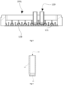
- FIG. 6, FIG.7 and FIG 8 Three examples from holders (102) are presented in FIG. 6, FIG.7 and FIG 8 . These examples figure the possibilitie of control the precise time when the containers (109) will be pressed against the heat transfer surface (101). These are designed to be used with pressing means (103) actuation system to compress the containers (109) against the heat transfer surface (101).
- the air is removed using an embodiment of contact layer (119), this in other cases can be replaced by a contact promoting material, such a liquid or other, applied on the holder (102) or on the heat transfer surface (101).
- the contact layer (119) when is directly added to the holder (102) can be made of any sticker or glued in a layer of teflon, polymer, or others. The thickness of this layer can go from 0.1 mm up to 2 mm. However the additional heat resistance added by this have to be taken in account for the general heat flow device.
- the holder with spring configuration (102a) will maintain the containers (109) on a ready to start lock up ( Fig. 2 ) position, by the mechanical resistance from the springs (118).
- the pressing means (103) forces the containers (109) with down force enough to override the spring elastic force, these, will meet the heat transfer surface (101) on a lock down ( Fig. 1 ) position and the thermal process will start.
- the compressible holder (102) when in locked up ( FIG.2 ) position have a distance from the heat transfer surface (101) that can go from 0.1 mm up to 10 mm, when in lockdown position ( Fig.1 ) the distance will be virtually 0 mm.
- This configuration comprises a spring (118) which can be an extension from the holder (102) itself or an added embodiment made of metal, polymer or other.
- the diameter from the spring (118) can differ from 3 mm up to 10 mm and can be disposed in several configurations and quantity.
- the extension of the spring (118) moving away from the bottom surface from the holder (102) can change from 0.1 mm up to 10 mm and will control the initial distance from the holder (102) to the heat transfer surface (101).
- the holder with tab configuration (102b) will maintain the containers (109) on a ready to start lock up ( Fig. 2 ) position, by the mechanical resistance from the tabs (120).
- the pressing means (103) forces the containers (109) with down force enough to override the tabs elastic force or break the tabs, these, will meet the heat transfer surface (101) on a lock down ( Fig. 1 ) position and the thermal process will start.
- the holders (102) when in locked up ( Fig. 2 ) position have a distance from the heat transfer surface (101) that can go from 0.1 mm up to 10 mm, when in lockdown position ( Fig. 1 ) the distance will be virtually 0 mm.
- This configuration comprises a tab (120) which can be an extension from the holder (102) itself or an added embodiment made of metal, polymer or other.
- the width from the tab (120) can differ from 2 mm up to 10 mm and the length from 4 mm to 15 mm, the tabs (120) can be disposed in several configurations and quantity.
- the extension of the tab (120) moving away from the bottom surface from the holder (102) can change from 0.1 mm up to 10 mm and will control the initial distance from the holder (102) to the heat transfer surface (101).
- the holder with pin configuration (102c), the holder (102) and the contact layer (119) are touching the heat transfer surface (101) when in lock up ( Fig. 2 ) position.
- the pressing means (103) will make down force on the containers (109) overriding the mechanical resistance from the pins (121) breake or flex these during the process.
- the pins can be disposed in any number or configuration within the cavities from the holder (102) and can be part of it or an added embodiment from any polymer, metal or other which is glued, encrusted or added by any other process of keeping it on a standby position.
- the pins (121) can be disposable, if breakable, or can be of several uses if flexible.
- the distance from the containers (109) bottom, to the contact layer (119) or heat transfer surface (101), depending on the configuration can be from a distance of 0.1 mm up to 10 mm.
- the pressing means (103) will mechanically actuate to compress the containers (109) to the heat transfer surface (101) or contact layer (119), depending on the configuration.
- the driver have two positions that are represented on Fig. 1 and Fig. 2 , lock down and lock up respectivelly.
- the pressing means (103) When the pressing means (103) is set to the lock up position ( Fig. 2 ) the containers (109) stand in a standby position separated from the cold heat transfer surface (101) by a air gap that can differ from 0.1 mm to 10 mm.
- the driver is on lock down ( FIG.1 ) position the existent air gap is virtually removed. This will be possible with a contact layer (119) or any fluid, paste, sticker or other that stays between the containers (109) and the heat transfer surface (101).
- the pressing means (103) can also be operated by a mechanical actuator controlled electronically.
- the compressor (108) is a heavy piece that countur the area of incidence from the containers (109), permiting to reach all containers (109) in a well distributed pressure zone.
- the compressor (108) is supported by a pivot (107) that allow the compressor (108) to adjust along all the containers (109) while the pressing means (103) moves to the lock down position ( Fig. 1 ).
- the pivot (107) position alongside with the design from the pressing means frame (104), will force the compressor (108) to stay in horizontal position during the downforce from the mechanism.
- This configuration of the pressing means frame (104) plus the pivot (107), have mechanical stops allowing a regular use from the holder (102) even if not all cavities are filled with containers (109). It is also represented the hinge (106) and the handler (105) as a possible configuration for this mechanism.
- Another aspect of this disclosure relates to a method of freezing biological solutions, using the previously described device, comprising the steps of:
- An important aspect of this disclosure is to attain a good contact between the bottom of the containers (123) and the heat transfer surface (101), to promote a controlled and uniform nucleation in all the containers. Therefore, as source of cold to induce nucleation, it can be used a heat transfer surface with a flat configuration (101a) or a recess configuration (101b) .
- the recess configuration (101b) will improve the heat transfer between the heat transfer surface (101) and the containers (109), since it can be filled with a specific height of a contact promoting material (such as a liquid or a polymer), as previously described.
- This recess configuration (101b) will allow that all the containers will have the same height of a contact promoting material independent of the number of containers used.
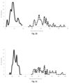
- Figs. 10 and 11 show the typical ranges of nucleation times of two aqueous solutions within the containers with a liquid height of 6 mm.
- all the samples nucleates in the range of 1 to 20 seconds, while this range increases to 26 to 67 seconds if no contact promoting material is used.
- 66% of the samples nucleates in a range of 5 seconds (between 5 and 10 seconds) using a contact promoting material, while the distributions of nucleation times without a contact promoting material is wider in a range of 25 seconds (between 32 and 57 seconds). Similar results were observed in the nucleation of 10% DMSO solution ( Fig. 11 ), where it can be seen that using a contact promoting material the nucleation occurs faster (5-20 seconds) and in a shorter range of time.
- the method and device of the present invention are used not only for freezing, but also for thawing a biological sample.
- the recess configuration with a specific height of contact promoting material provides a greater degree of nucleation control which likely impacts other performance aspects and characteristics of the freezed solution.
- Another important aspect of this disclosure is to decouple the nucleation from the controlled-rate freezing. For this purpose, is necessary to ensure that in the nucleation step the fraction of liquid that freezes should not be higher than 20%, in accordance with the invention not higher than 10%, and then the remaining liquid fraction is freeze at a controlled rate.
- the samples after nucleation of a small fraction of solution it is necessary to withdraw the samples from the heat transfer surface so that the solution do not continue to freeze uncontrollably. So, after the time required for nucleation, the samples are slightly spaced away from the heat transfer surface so that the pre-nucleated solution fraction remains frozen and the liquid fraction remains at approximately 0 °C. Finally, with all the samples with a fraction of solution freezed and the remaining liquid at the same temperature (0 °C), these can then be frozen unidirectional bottom-up manner by applying a controlled freezing rate.
Landscapes
- Life Sciences & Earth Sciences (AREA)
- Health & Medical Sciences (AREA)
- Engineering & Computer Science (AREA)
- Dentistry (AREA)
- General Health & Medical Sciences (AREA)
- Wood Science & Technology (AREA)
- Zoology (AREA)
- Environmental Sciences (AREA)
- Apparatus Associated With Microorganisms And Enzymes (AREA)
- Micro-Organisms Or Cultivation Processes Thereof (AREA)
- Sampling And Sample Adjustment (AREA)
- Peptides Or Proteins (AREA)
Claims (14)
- Verfahren zum geometrischen, von unten nach oben gerichteten Einfrieren und/oder zur Keimbildung einer Probenlösung, umfassend die folgenden Schritte:Vorkühlen einer Vorrichtung auf eine Temperatur, die wesentlich unter der Keimbildungstemperatur der Lösung liegt, wobei die Vorrichtung an der Unterseite eine Fläche für die Wärmeübertragung und Druckmittel umfasst;Einsetzen eines Behälters, der die biologische Lösung enthält, in eine Halterung, wobei die Halterung ein Material mit geringer Wärmeleitfähigkeit umfasst;Inkontaktbringen des Behälters mit der Fläche für die Wärmeübertragung durch Drücken der Halterung gegen die Fläche für die Wärmeübertragung, bis ein Anteil von 10 % des Gesamtvolumens der Probe eingefroren ist;Unterbrechen des Kontakts zwischen dem Behälter und der Fläche für die Wärmeübertragung durch Beabstanden des Behälters von der Fläche für die Wärmeübertragung;Inkontaktbringen des Behälters mit der Fläche für die Wärmeübertragung bei einer vordefinierten Einfriergeschwindigkeit durch Drücken der Halterung gegen die Fläche für die Wärmeübertragung, so dass das Einfrieren der biologischen Lösung gleichförmig erfolgt;bis das gesamte Volumen der Lösung gefroren ist.
- Verfahren nach dem vorangehenden Anspruch, umfassend eine Vielzahl von Behältern.
- Verfahren nach einem der vorangehenden Ansprüche, wobei die kontrollierte Einfriergeschwindigkeit der biologischen Lösung innerhalb des genannten Behälters zwischen 0,1 °C/Min. - 100,0 °C/Min., bevorzugt 0,5 °C/Min. - 10 °C/Min., besonders bevorzugt 1 °C/Min. - 5 °C/Min. beträgt.
- Verfahren nach einem der vorangehenden Ansprüche, wobei der Schritt des Vorkühlens der Vorrichtung bei einer Temperatur von weniger als -20 °C, bevorzugt weniger als -30 °C, besonders bevorzugt weniger als -40 °C erfolgt.
- Verfahren nach einem der vorangehenden Ansprüche, wobei der Schritt des Unterbrechens des Kontakts zwischen dem Behälter und der Fläche für die Wärmeübertragung dadurch erfolgt, dass der Behälter von der Fläche für die Wärmeübertragung entfernt wird, bevorzugt durch einen Luftspalt von 0,1 mm bis zu 15 mm, während eine biologische Lösung bei einer Temperatur nahe 0 °C gehalten wird.
- Vorrichtung zum Durchführen des Verfahrens nach einem der vorangehenden Ansprüche, umfassend:eine Fläche für die Wärmeübertragung (101, 101a, 101b) am Boden, wobei die Fläche für die Wärmeübertragung bevorzugt aus einem leitfähigen Material, ausgewählt aus rostfreiem Stahl, Kupfer, Aluminium oder Mischungen davon, hergestellt ist;eine Halterung (102a, 102b, 102c), umfassend mindestens eine Aussparung für einen Behälter (109), wobei die Halterung ein Material mit geringer Wärmeleitfähigkeit umfasst, wobei das Material mit geringer Wärmeleitfähigkeit bevorzugt aus Kunststoff, Keramik oder einem Verbundwerkstoff besteht;ein Druckmittel (103), dass so konfiguriert ist, dass es den Behälter in Kontakt mit der Fläche für die Wärmeübertragung bringt, um die Wärme von der Fläche für die Wärmeübertragung auf den Behälter zu übertragen, und den Behälter von der Fläche für die Wärmeübertragung entfernt und den Behälter mit der Fläche für die Wärmeübertragung erneut in Kontakt bringt;wobei die Wärmeübertragung vom Boden des Behälters aus erfolgt, wodurch eine kontrollierte Keimbildung ermöglicht wird;wobei die Halterung ein zusammendrückbares Mittel umfasst, das aus einer Feder (118), einem Zapfen (120) oder einem Stift (121) ausgewählt ist, so dass die Halterung zwischen einer ersten Position und einer zweiten Position zusammendrückbar ist, wobei der Boden des Behälters in der ersten Position in Kontakt mit der Fläche für die Wärmeübertragung steht und in der zweiten Position der Boden des Behälters von der Fläche für die Wärmeübertragung beabstandet ist.
- Vorrichtung nach dem vorangehenden Anspruch, wobei die Druckmittel einen Kompressor (108) zum Kontern der Halterung umfassen, so dass ein gleichmäßig verteilter Druck auf die Halterung ausgeübt wird, wobei bevorzugt ein manueller oder ein mechanisch gleichmäßig verteilter Druck auf die Halterung ausgeübt wird.
- Vorrichtung nach einem der Ansprüche 6 oder 7, wobei die Druckmittel so konfiguriert sind, dass: sie einen Teil des Behälters in Kontakt mit der Fläche für die Wärmeübertragung bringen, Wärme von der Fläche für die Wärmeübertragung auf den Teil des Behälters übertragen, den Behälter von der Fläche für die Wärmeübertragung entfernen und den Teil des Behälters, der in Kontakt mit der Fläche für die Wärmeübertragung steht, wieder einsetzen, wobei der Teil des Behälters bevorzugt der Boden des Behälters ist.
- Vorrichtung nach einem der Ansprüche 6 bis 8, wobei die Halterung so konfiguriert ist, dass sie gegen eine flache Struktur der Fläche für die Wärmeübertragung (101a) oder gegen eine eingeschnittene Struktur der Fläche für die Wärmeübertragung (101b) drückt, wobei die eingeschnittene Plateaustruktur der Fläche für die Wärmeübertragung bevorzugt eine Vertiefung mit einer Tiefe zwischen 0,5-3 mm ist.
- Vorrichtung nach dem vorangehenden Anspruch, wobei die eingeschnittene Struktur der Fläche für die Wärmeübertragung einen Kanal (116) zum Entfernen eines Flüssigkeitsüberschusses, bevorzugt zum Entfernen eines Überschusses eines kontaktfördernden Materials, aufweist.
- Vorrichtung nach einem der Ansprüche 6 bis 10, umfassend einem Kühlmittelbehälter zum Speichern eines Kühlmittels, und/oder Rippen (115) und/oder einen Rippenträger (112).
- Vorrichtung nach einem der Ansprüche 6 bis 11, umfassend einen Isolierrahmen (111), um die Fläche für die Wärmeübertragung gegenüber der Raumtemperatur zu isolieren und den Benutzer zu schützen.
- Vorrichtung nach einem der Ansprüche 6 bis 12, umfassend eine Kontaktschicht zum Entfernen der Restluft zwischen der Fläche für die Wärmeübertragung und dem Behälter, wobei die Kontaktschicht bevorzugt eine Flüssigkeit, eine Paste, ein Papier oder ein Aufkleber ist, wobei die Kontaktschicht besonders bevorzugt eine Höhe von 0,1 mm bis 3 mm aufweist.
- Vorrichtung nach einem der Ansprüche 6 bis 13, ferner umfassend den Behälter (109), wobei der Behälter so konfiguriert ist, dass er eine biologische Lösung enthält, und wobei die Wand und der Boden des Behälters aus unterschiedlichen Materialien hergestellt sind, wobei die Wand des Behälters bevorzugt aus Polymeren, Keramik, Glas oder anderen gering wärmeleitenden Materialien hergestellt ist, und wobei der Boden des Behälters aus einem Material mit hoher Leitfähigkeit, ausgewählt aus rostfreiem Stahl, Aluminium oder anderen Materialien hergestellt ist, und die Wand des Behälters aus gering leitenden Materialien wie Polymeren, Glas oder anderen Materialien besteht.
Applications Claiming Priority (2)
| Application Number | Priority Date | Filing Date | Title |
|---|---|---|---|
| PT11515318 | 2018-11-15 | ||
| PCT/IB2019/059836 WO2020100105A1 (en) | 2018-11-15 | 2019-11-15 | Device and method for freezing a biological solution |
Publications (3)
| Publication Number | Publication Date |
|---|---|
| EP3879979A1 EP3879979A1 (de) | 2021-09-22 |
| EP3879979C0 EP3879979C0 (de) | 2025-02-26 |
| EP3879979B1 true EP3879979B1 (de) | 2025-02-26 |
Family
ID=68965944
Family Applications (1)
| Application Number | Title | Priority Date | Filing Date |
|---|---|---|---|
| EP19823995.6A Active EP3879979B1 (de) | 2018-11-15 | 2019-11-15 | Vorrichtung und verfahren zum einfrieren einer biologischen lösung |
Country Status (6)
| Country | Link |
|---|---|
| US (1) | US12302895B2 (de) |
| EP (1) | EP3879979B1 (de) |
| JP (2) | JP2022507641A (de) |
| CN (1) | CN112804875B (de) |
| CA (1) | CA3111614A1 (de) |
| WO (1) | WO2020100105A1 (de) |
Families Citing this family (3)
| Publication number | Priority date | Publication date | Assignee | Title |
|---|---|---|---|---|
| CN115074238A (zh) * | 2022-08-07 | 2022-09-20 | 上海安库生医生物科技有限公司 | 一种干式细胞复苏仪 |
| WO2024053180A1 (ja) * | 2022-09-06 | 2024-03-14 | リンナイ株式会社 | 予混合装置 |
| CN117918338B (zh) * | 2024-03-19 | 2024-05-24 | 潍坊吉涛医学科技有限公司 | 一种妇科肿瘤病理用临存设备 |
Family Cites Families (18)
| Publication number | Priority date | Publication date | Assignee | Title |
|---|---|---|---|---|
| JPH0121923Y2 (de) * | 1984-11-15 | 1989-06-29 | ||
| JPH05196331A (ja) * | 1992-11-13 | 1993-08-06 | Toshiba Corp | 自動製氷装置 |
| US6453683B1 (en) * | 2001-05-22 | 2002-09-24 | Integrated Biosystems, Inc. | Tapered slot cryopreservation system with controlled dendritic freezing front velocity |
| CA2509037A1 (en) | 2002-12-13 | 2004-07-01 | Integrated Biosystems, Inc. | Scaled down freezing and thawing system for bioparmaceuticals and biologics |
| US20060096738A1 (en) * | 2004-11-05 | 2006-05-11 | Aavid Thermalloy, Llc | Liquid cold plate heat exchanger |
| US8794013B2 (en) * | 2006-02-10 | 2014-08-05 | Praxair Technology, Inc. | Method and system for nucleation control in a controlled rate freezer (CRF) |
| DE102008048709B4 (de) * | 2008-09-24 | 2018-05-17 | Ingenieurbüro und Plastverarbeitung Quinger GmbH | Verfahren und Vorrichtung zur Temperierung von Gewebeteilen |
| JP4680311B2 (ja) * | 2009-09-16 | 2011-05-11 | シャープ株式会社 | 冷凍冷蔵庫の製氷装置 |
| US8371132B2 (en) * | 2009-11-23 | 2013-02-12 | Sartorius Stedim North America Inc. | Systems and methods for use in freezing, thawing, and storing biopharmaceutical materials |
| CN103140731B (zh) * | 2010-09-28 | 2015-12-16 | 巴克斯特国际公司 | 使用间隙冷冻来优化冻干的成核和结晶 |
| US20130052730A1 (en) | 2011-08-26 | 2013-02-28 | Biocision, Llc | Methods and system for cryogenic preservation of cells |
| US9121637B2 (en) * | 2013-06-25 | 2015-09-01 | Millrock Technology Inc. | Using surface heat flux measurement to monitor and control a freeze drying process |
| US10285420B2 (en) | 2013-07-30 | 2019-05-14 | California Institute Of Technology | Magnetite-based heterogeneous ice-crystal nucleation |
| DE102014018308A1 (de) * | 2014-12-10 | 2016-06-16 | Fraunhofer-Gesellschaft zur Förderung der angewandten Forschung e.V. | Temperierkörper für eine Multiwell-Platte und Verfahren und Vorrichtung zum Einfrieren und/oder Auftauen von biologischen Proben |
| JP6138223B2 (ja) * | 2014-12-16 | 2017-05-31 | ヤマトエスロン株式会社 | Dna増幅方法、dna増幅構造体及びこれを用いたdna検出装置 |
| GB201506541D0 (en) * | 2015-04-16 | 2015-06-03 | Lamb S | Improved methods for cryopreservation of biological materials |
| EP3199023B1 (de) | 2016-01-27 | 2021-01-20 | Sartorius Stedim North America Inc. | Verfahren und system zum einfrieren biopharmazeutischer flüssigkeiten |
| JP6337412B2 (ja) | 2017-02-09 | 2018-06-06 | 三菱重工冷熱株式会社 | 水溶液の過冷却制御方法および水溶液の過冷却制御装置、冷却装置および冷却システム |
-
2019
- 2019-11-15 CN CN201980065699.0A patent/CN112804875B/zh active Active
- 2019-11-15 WO PCT/IB2019/059836 patent/WO2020100105A1/en not_active Ceased
- 2019-11-15 EP EP19823995.6A patent/EP3879979B1/de active Active
- 2019-11-15 CA CA3111614A patent/CA3111614A1/en active Pending
- 2019-11-15 JP JP2021526773A patent/JP2022507641A/ja active Pending
- 2019-11-15 US US17/287,767 patent/US12302895B2/en active Active
-
2024
- 2024-05-08 JP JP2024075742A patent/JP2024112830A/ja active Pending
Non-Patent Citations (1)
| Title |
|---|
| MIGUEL A. RODRIGUES ET AL: "The importance of heat flow direction for reproducible and homogeneous freezing of bulk protein solutions", BIOTECHNOLOGY PROGRESS, vol. 29, no. 5, 27 June 2013 (2013-06-27), Hoboken, USA, pages 1212 - 1221, XP055676577, ISSN: 8756-7938, DOI: 10.1002/btpr.1771 * |
Also Published As
| Publication number | Publication date |
|---|---|
| US20210392874A1 (en) | 2021-12-23 |
| CA3111614A1 (en) | 2020-05-22 |
| JP2024112830A (ja) | 2024-08-21 |
| CN112804875A (zh) | 2021-05-14 |
| CN112804875B (zh) | 2022-08-05 |
| US12302895B2 (en) | 2025-05-20 |
| EP3879979C0 (de) | 2025-02-26 |
| JP2022507641A (ja) | 2022-01-18 |
| WO2020100105A1 (en) | 2020-05-22 |
| EP3879979A1 (de) | 2021-09-22 |
Similar Documents
| Publication | Publication Date | Title |
|---|---|---|
| EP3879979B1 (de) | Vorrichtung und verfahren zum einfrieren einer biologischen lösung | |
| KR102103237B1 (ko) | 멀티웰 플레이트용 온도제어요소와 생물학적 시료의 냉동 및/또는 해동을 위한 방법 및 장치 | |
| US12075773B2 (en) | Capillary assisted vitrification processes and devices | |
| US11441979B2 (en) | Thawing methods and apparatus | |
| JP2004534601A (ja) | 樹脂状凍結境界面速度が制御される冷凍保存システム | |
| US20090255938A1 (en) | Cryogenic storage container | |
| Steif et al. | Cryomacroscopy of vitrification II: Experimental observations and analysis of fracture formation in vitrified VS55 and DP6 | |
| Luft et al. | Microbatch macromolecular crystallization on a thermal gradient | |
| EP3879978B1 (de) | Isolator zur verhinderung von behälterschäden und -brüchen durch gefrieren von wässrigen lösungen mit biologischen materialien | |
| JP7408099B2 (ja) | 生体試料の少なくとも一部を凍結することに関する装置および方法 | |
| US20130052730A1 (en) | Methods and system for cryogenic preservation of cells | |
| US7604930B1 (en) | Methods and devices for cryopreservation of biological cells and tissues | |
| JP2002204690A (ja) | 細胞付細胞培養器,その製造方法及びその使用方法 | |
| Potter et al. | Use of plastic capillaries for macromolecular crystallization |
Legal Events
| Date | Code | Title | Description |
|---|---|---|---|
| STAA | Information on the status of an ep patent application or granted ep patent |
Free format text: STATUS: UNKNOWN |
|
| STAA | Information on the status of an ep patent application or granted ep patent |
Free format text: STATUS: THE INTERNATIONAL PUBLICATION HAS BEEN MADE |
|
| PUAI | Public reference made under article 153(3) epc to a published international application that has entered the european phase |
Free format text: ORIGINAL CODE: 0009012 |
|
| STAA | Information on the status of an ep patent application or granted ep patent |
Free format text: STATUS: REQUEST FOR EXAMINATION WAS MADE |
|
| 17P | Request for examination filed |
Effective date: 20210604 |
|
| AK | Designated contracting states |
Kind code of ref document: A1 Designated state(s): AL AT BE BG CH CY CZ DE DK EE ES FI FR GB GR HR HU IE IS IT LI LT LU LV MC MK MT NL NO PL PT RO RS SE SI SK SM TR |
|
| DAV | Request for validation of the european patent (deleted) | ||
| DAX | Request for extension of the european patent (deleted) | ||
| GRAP | Despatch of communication of intention to grant a patent |
Free format text: ORIGINAL CODE: EPIDOSNIGR1 |
|
| STAA | Information on the status of an ep patent application or granted ep patent |
Free format text: STATUS: GRANT OF PATENT IS INTENDED |
|
| INTG | Intention to grant announced |
Effective date: 20241014 |
|
| GRAS | Grant fee paid |
Free format text: ORIGINAL CODE: EPIDOSNIGR3 |
|
| GRAA | (expected) grant |
Free format text: ORIGINAL CODE: 0009210 |
|
| STAA | Information on the status of an ep patent application or granted ep patent |
Free format text: STATUS: THE PATENT HAS BEEN GRANTED |
|
| AK | Designated contracting states |
Kind code of ref document: B1 Designated state(s): AL AT BE BG CH CY CZ DE DK EE ES FI FR GB GR HR HU IE IS IT LI LT LU LV MC MK MT NL NO PL PT RO RS SE SI SK SM TR |
|
| REG | Reference to a national code |
Ref country code: GB Ref legal event code: FG4D |
|
| REG | Reference to a national code |
Ref country code: DE Ref legal event code: R096 Ref document number: 602019066580 Country of ref document: DE |
|
| REG | Reference to a national code |
Ref country code: IE Ref legal event code: FG4D |
|
| U01 | Request for unitary effect filed |
Effective date: 20250324 |
|
| U07 | Unitary effect registered |
Designated state(s): AT BE BG DE DK EE FI FR IT LT LU LV MT NL PT RO SE SI Effective date: 20250328 |
|
| PG25 | Lapsed in a contracting state [announced via postgrant information from national office to epo] |
Ref country code: RS Free format text: LAPSE BECAUSE OF FAILURE TO SUBMIT A TRANSLATION OF THE DESCRIPTION OR TO PAY THE FEE WITHIN THE PRESCRIBED TIME-LIMIT Effective date: 20250526 |
|
| PG25 | Lapsed in a contracting state [announced via postgrant information from national office to epo] |
Ref country code: PL Free format text: LAPSE BECAUSE OF FAILURE TO SUBMIT A TRANSLATION OF THE DESCRIPTION OR TO PAY THE FEE WITHIN THE PRESCRIBED TIME-LIMIT Effective date: 20250226 |
|
| PG25 | Lapsed in a contracting state [announced via postgrant information from national office to epo] |
Ref country code: ES Free format text: LAPSE BECAUSE OF FAILURE TO SUBMIT A TRANSLATION OF THE DESCRIPTION OR TO PAY THE FEE WITHIN THE PRESCRIBED TIME-LIMIT Effective date: 20250226 |
|
| PG25 | Lapsed in a contracting state [announced via postgrant information from national office to epo] |
Ref country code: IS Free format text: LAPSE BECAUSE OF FAILURE TO SUBMIT A TRANSLATION OF THE DESCRIPTION OR TO PAY THE FEE WITHIN THE PRESCRIBED TIME-LIMIT Effective date: 20250626 Ref country code: NO Free format text: LAPSE BECAUSE OF FAILURE TO SUBMIT A TRANSLATION OF THE DESCRIPTION OR TO PAY THE FEE WITHIN THE PRESCRIBED TIME-LIMIT Effective date: 20250526 |
|
| PG25 | Lapsed in a contracting state [announced via postgrant information from national office to epo] |
Ref country code: HR Free format text: LAPSE BECAUSE OF FAILURE TO SUBMIT A TRANSLATION OF THE DESCRIPTION OR TO PAY THE FEE WITHIN THE PRESCRIBED TIME-LIMIT Effective date: 20250226 |
|
| PG25 | Lapsed in a contracting state [announced via postgrant information from national office to epo] |
Ref country code: GR Free format text: LAPSE BECAUSE OF FAILURE TO SUBMIT A TRANSLATION OF THE DESCRIPTION OR TO PAY THE FEE WITHIN THE PRESCRIBED TIME-LIMIT Effective date: 20250527 |
|
| PG25 | Lapsed in a contracting state [announced via postgrant information from national office to epo] |
Ref country code: SM Free format text: LAPSE BECAUSE OF FAILURE TO SUBMIT A TRANSLATION OF THE DESCRIPTION OR TO PAY THE FEE WITHIN THE PRESCRIBED TIME-LIMIT Effective date: 20250226 |
|
| PG25 | Lapsed in a contracting state [announced via postgrant information from national office to epo] |
Ref country code: CZ Free format text: LAPSE BECAUSE OF FAILURE TO SUBMIT A TRANSLATION OF THE DESCRIPTION OR TO PAY THE FEE WITHIN THE PRESCRIBED TIME-LIMIT Effective date: 20250226 |
|
| PG25 | Lapsed in a contracting state [announced via postgrant information from national office to epo] |
Ref country code: SK Free format text: LAPSE BECAUSE OF FAILURE TO SUBMIT A TRANSLATION OF THE DESCRIPTION OR TO PAY THE FEE WITHIN THE PRESCRIBED TIME-LIMIT Effective date: 20250226 |
|
| REG | Reference to a national code |
Ref country code: CH Ref legal event code: U11 Free format text: ST27 STATUS EVENT CODE: U-0-0-U10-U11 (AS PROVIDED BY THE NATIONAL OFFICE) Effective date: 20251201 |