EP3879121B1 - Support for a bearing for electric pump and electric pump with such support - Google Patents
Support for a bearing for electric pump and electric pump with such support Download PDFInfo
- Publication number
- EP3879121B1 EP3879121B1 EP21152603.3A EP21152603A EP3879121B1 EP 3879121 B1 EP3879121 B1 EP 3879121B1 EP 21152603 A EP21152603 A EP 21152603A EP 3879121 B1 EP3879121 B1 EP 3879121B1
- Authority
- EP
- European Patent Office
- Prior art keywords
- support
- bearing
- receptacle
- electric pump
- axis
- Prior art date
- Legal status (The legal status is an assumption and is not a legal conclusion. Google has not performed a legal analysis and makes no representation as to the accuracy of the status listed.)
- Active
Links
- 238000007789 sealing Methods 0.000 claims description 22
- 239000007769 metal material Substances 0.000 claims description 7
- 230000000295 complement effect Effects 0.000 claims description 2
- 229910001220 stainless steel Inorganic materials 0.000 claims description 2
- 239000010935 stainless steel Substances 0.000 claims description 2
- 239000000463 material Substances 0.000 description 7
- 238000005452 bending Methods 0.000 description 3
- 229910052782 aluminium Inorganic materials 0.000 description 2
- XAGFODPZIPBFFR-UHFFFAOYSA-N aluminium Chemical compound [Al] XAGFODPZIPBFFR-UHFFFAOYSA-N 0.000 description 2
- 230000000670 limiting effect Effects 0.000 description 2
- 239000007788 liquid Substances 0.000 description 2
- 230000002860 competitive effect Effects 0.000 description 1
- 238000003780 insertion Methods 0.000 description 1
- 230000037431 insertion Effects 0.000 description 1
- 229910052751 metal Inorganic materials 0.000 description 1
- 239000002184 metal Substances 0.000 description 1
- 238000000034 method Methods 0.000 description 1
- 238000012986 modification Methods 0.000 description 1
- 230000004048 modification Effects 0.000 description 1
- 238000005086 pumping Methods 0.000 description 1
- XLYOFNOQVPJJNP-UHFFFAOYSA-N water Substances O XLYOFNOQVPJJNP-UHFFFAOYSA-N 0.000 description 1
Images


Classifications
-
- F—MECHANICAL ENGINEERING; LIGHTING; HEATING; WEAPONS; BLASTING
- F04—POSITIVE - DISPLACEMENT MACHINES FOR LIQUIDS; PUMPS FOR LIQUIDS OR ELASTIC FLUIDS
- F04D—NON-POSITIVE-DISPLACEMENT PUMPS
- F04D29/00—Details, component parts, or accessories
- F04D29/04—Shafts or bearings, or assemblies thereof
- F04D29/046—Bearings
- F04D29/0462—Bearing cartridges
-
- F—MECHANICAL ENGINEERING; LIGHTING; HEATING; WEAPONS; BLASTING
- F04—POSITIVE - DISPLACEMENT MACHINES FOR LIQUIDS; PUMPS FOR LIQUIDS OR ELASTIC FLUIDS
- F04D—NON-POSITIVE-DISPLACEMENT PUMPS
- F04D1/00—Radial-flow pumps, e.g. centrifugal pumps; Helico-centrifugal pumps
- F04D1/06—Multi-stage pumps
-
- F—MECHANICAL ENGINEERING; LIGHTING; HEATING; WEAPONS; BLASTING
- F04—POSITIVE - DISPLACEMENT MACHINES FOR LIQUIDS; PUMPS FOR LIQUIDS OR ELASTIC FLUIDS
- F04D—NON-POSITIVE-DISPLACEMENT PUMPS
- F04D13/00—Pumping installations or systems
- F04D13/02—Units comprising pumps and their driving means
- F04D13/06—Units comprising pumps and their driving means the pump being electrically driven
-
- F—MECHANICAL ENGINEERING; LIGHTING; HEATING; WEAPONS; BLASTING
- F04—POSITIVE - DISPLACEMENT MACHINES FOR LIQUIDS; PUMPS FOR LIQUIDS OR ELASTIC FLUIDS
- F04D—NON-POSITIVE-DISPLACEMENT PUMPS
- F04D29/00—Details, component parts, or accessories
- F04D29/02—Selection of particular materials
- F04D29/026—Selection of particular materials especially adapted for liquid pumps
-
- F—MECHANICAL ENGINEERING; LIGHTING; HEATING; WEAPONS; BLASTING
- F04—POSITIVE - DISPLACEMENT MACHINES FOR LIQUIDS; PUMPS FOR LIQUIDS OR ELASTIC FLUIDS
- F04D—NON-POSITIVE-DISPLACEMENT PUMPS
- F04D29/00—Details, component parts, or accessories
- F04D29/04—Shafts or bearings, or assemblies thereof
- F04D29/046—Bearings
- F04D29/049—Roller bearings
-
- F—MECHANICAL ENGINEERING; LIGHTING; HEATING; WEAPONS; BLASTING
- F04—POSITIVE - DISPLACEMENT MACHINES FOR LIQUIDS; PUMPS FOR LIQUIDS OR ELASTIC FLUIDS
- F04D—NON-POSITIVE-DISPLACEMENT PUMPS
- F04D29/00—Details, component parts, or accessories
- F04D29/08—Sealings
- F04D29/10—Shaft sealings
- F04D29/106—Shaft sealings especially adapted for liquid pumps
-
- F—MECHANICAL ENGINEERING; LIGHTING; HEATING; WEAPONS; BLASTING
- F04—POSITIVE - DISPLACEMENT MACHINES FOR LIQUIDS; PUMPS FOR LIQUIDS OR ELASTIC FLUIDS
- F04D—NON-POSITIVE-DISPLACEMENT PUMPS
- F04D29/00—Details, component parts, or accessories
- F04D29/40—Casings; Connections of working fluid
- F04D29/42—Casings; Connections of working fluid for radial or helico-centrifugal pumps
- F04D29/426—Casings; Connections of working fluid for radial or helico-centrifugal pumps especially adapted for liquid pumps
-
- F—MECHANICAL ENGINEERING; LIGHTING; HEATING; WEAPONS; BLASTING
- F04—POSITIVE - DISPLACEMENT MACHINES FOR LIQUIDS; PUMPS FOR LIQUIDS OR ELASTIC FLUIDS
- F04D—NON-POSITIVE-DISPLACEMENT PUMPS
- F04D29/00—Details, component parts, or accessories
- F04D29/60—Mounting; Assembling; Disassembling
- F04D29/62—Mounting; Assembling; Disassembling of radial or helico-centrifugal pumps
- F04D29/628—Mounting; Assembling; Disassembling of radial or helico-centrifugal pumps especially adapted for liquid pumps
Definitions
- the present invention relates to a support for a bearing for electric pump.
- the invention also relates to an electric pump with such a bearing support.
- An electric pump is a device for pumping a liquid, which comprises a wet region, which has intake and delivery ducts, in which one or more impellers are submerged, diffusers being interleaved between said impellers, which are keyed on a rotating shaft turned by an electric motor.
- This electric motor comprises a stator and a rotor, from which the rotating shaft extends.
- the electric motor see e.g. EP 3290712 A1 , is contained in a substantially tubular motor housing, which is isolated from the wet region, on the rotating shaft, by means of a mechanical seal.
- This mechanical seal surrounds the rotating shaft and is carried by an annular supporting element which also surrounds the rotating shaft at the interface between the motor housing and the wet region.
- the rotating shaft supports two bearings between which the rotor of the electric motor is interposed.
- the two bearings are adapted to keep the rotating shaft, and therefore the rotor, in axial alignment during operation and when not in use.
- one of the two bearings is arranged, inside the motor housing, proximate to the interface region between the latter and the wet region.
- the bearing supporting element proximate to the wet region is made of metallic material, usually aluminum, while the supporting element of the mechanical seal is made of plastic material.
- the support of the bearing made of metal, is centered on the support of the mechanical seal, made of plastic material.
- the support for the mechanical seal made of plastic material entails that it is impossible to achieve dimensional tolerances of the centering between the two supports that would be achieved by using other materials.
- a support for the bearing and of a support for the sealing element which are separate and are proximate to/at the interface between the wet region and the motor housing can determine a non-perfect coaxiality between the two supports, also as a result of deformations on the support for the mechanical seal made of plastic material, and therefore the generation of bending moments on the rotating shaft, with consequent malfunctioning of the electric pump.
- a non-perfect coaxiality between the support of the mechanical seal and the support of the bearing reduces the operating life of the seal and therefore of the electric pump.
- the aim of the present invention is to provide a support for a bearing for electric pump that is capable of improving the background art in one or more of the aspects mentioned above.
- an object of the invention is to provide a support for a bearing for electric pump that allows to reduce the number of components of the electric pump.
- Another object of the invention is to devise a support for a mechanical seal for an electric pump that is less subject to deformations than similar bearing supports of a known type.
- Another object of the invention is to provide a support for a bearing for electric pump that allows to achieve centering dimensional tolerances with the support for the mechanical seal which are lower than those achieved by similar supports of a known type.
- a further object of the invention is to devise a support for a bearing for electric pump that allows a better coaxiality with the support of the sealing element for the wet region than similar supports of a known type and therefore allows to reduce the bending moments generated on the rotating shaft.
- a still further object of the present invention is to overcome the drawbacks of the background art in a manner that is alternative to any existing solutions.
- Another object of the invention is to provide a support for a bearing for electric pump that is highly reliable, relatively easy to provide and at competitive costs.
- a support for a bearing 12 for electric pump 50 according to the invention is generally designated by the reference numeral 10.
- the support 10 has a contoured portion which forms in a single body:
- the invention provides a common support for the bearing and the mechanical seal.
- the receptacle 13 for the sealing element 14 is arranged inside a flange element 26 which comprises a disk-like portion 15 provided with a first through hole 25 and a surface from which an annular portion 16 extends which is coaxial to the disk-like portion 15 and surrounds the first through hole 25.
- the sealing element 14 which is constituted by a mechanical seal, is inserted into the annular portion 16 and is seated in the first through hole at/proximate to the disk-like portion 15.
- the support 10 is made of metallic material, such as for example aluminum, and has an element 17 for covering the annular portion 16, which forms the receptacle 13 for the sealing element 14.
- the sealing element 14 is accommodated inside the covering element 17 in the first through hole 25 of the annular portion 16.
- the covering element 17 is made of metallic material, advantageously stainless steel, and is adapted to protect the support 10 from water, being arranged at the interface between the wet region 51 of the electric pump 50 and its motor housing 52.
- the covering element 17 is a first covering element
- the sealing element 14 rests inside the covering element 17 and is surrounded by it.
- the support 10 comprises, at the opposite end with respect to the end provided with the receptacle 13 for the sealing element 14, a tray element 19 which has a circular profile with a flanged perimetric rim 20.
- the tray element 19 comprises a base 21 and a side wall 22 from which the flanged rim 20 is extended.
- the base 21 is provided with a second through hole 23 for the insertion of the rotating shaft 18 of the electric pump 50.
- the inside diameter of the tubular portion 24 is comparable with the outside diameter of the bearing 12 and is greater than the diameter of the second through hole 23.
- the bearing 12 is inserted in the tubular portion 24 and is substantially in contact with the base 21 of the tray portion 19.
- the tubular portion 24, the tray element 19, the disk-like portion 15 and the annular portion 16 are coaxial and their axis coincides with the extension axis X of the support 10.
- the flange element 26 and the tray element 19 are connected and joined by one or more bridge elements 27 which give greater stiffness to the support 10.
- These bridge elements 27 have a substantially triangular profile.
- the bridge elements 27 are four, arranged in a radial manner with respect to the extension axis X of the support 10 and mutually equidistant.
- the first through hole 25 and the second through hole 23 form a single passage for the rotating shaft 18 of the electric pump 50, around which the bridge elements 27 are arranged.
- the bearing 12 and the sealing element 14 are arranged at opposite ends and are directed toward the outside of the support 10, therefore toward opposite sides of the support 10.
- Figure 2 shows a cross-section of an electric pump 50 comprising a support 10 according to the invention.
- the electric pump 50 has, in the configuration for use, a vertical extension and comprises, from the bottom upward:
- One or more impellers 54 keyed on the rotating shaft 18 are arranged in the wet region 51.
- a motor is arranged inside the motor housing 52 and comprises a rotor 55 for the movement of the rotating shaft 18, which is keyed thereon, and a stator 56 which surrounds the rotor 55.
- the rotating shaft 18 is kept in axial alignment by means of two bearings arranged at the ends of the rotor 55, respectively:
- the support 10 for the bearing 12, as described above, is arranged inside the electric pump 50, at the interface between the wet region 51 and the motor housing 52.
- the sealing element 14 is keyed on the rotating shaft 18, at the interface between the wet region 51 and the motor housing 52, and hinders the passage of the liquid from the wet region 51 to the motor housing 52.
- the invention achieves the intended aim and objects, providing a support for a bearing for electric pump which allows to reduce the number of components of the electric pump.
- the invention provides a common support to the bearing and to the mechanical seal which is completely made of metallic material.
- the invention provides a support for a bearing for electric pump which allows to achieve centering dimensional tolerances with the support for the mechanical seal that are smaller than those achieved by similar supports of a known type, since it is provided monolithically with the support for the mechanical seal and is made of metallic material.
- the invention provides a support for a bearing for electric pump which allows a better coaxiality with the support of the sealing element for the wet region than similar supports of a known type and therefore allows to reduce the bending moments generated on the rotating shaft, since its flange element, which defines the receptacle for the sealing element, and its tubular element, which defines the receptacle for the bearing, are coaxial.
- the materials used may be any according to the requirements and the state of the art.
Landscapes
- Engineering & Computer Science (AREA)
- Mechanical Engineering (AREA)
- General Engineering & Computer Science (AREA)
- Structures Of Non-Positive Displacement Pumps (AREA)
Description
- The present invention relates to a support for a bearing for electric pump.
- The invention also relates to an electric pump with such a bearing support.
- An electric pump is a device for pumping a liquid, which comprises a wet region, which has intake and delivery ducts, in which one or more impellers are submerged, diffusers being interleaved between said impellers, which are keyed on a rotating shaft turned by an electric motor.
- This electric motor comprises a stator and a rotor, from which the rotating shaft extends.
- Usually, the electric motor, see e.g.
EP 3290712 A1 , is contained in a substantially tubular motor housing, which is isolated from the wet region, on the rotating shaft, by means of a mechanical seal. - This mechanical seal surrounds the rotating shaft and is carried by an annular supporting element which also surrounds the rotating shaft at the interface between the motor housing and the wet region.
- The rotating shaft supports two bearings between which the rotor of the electric motor is interposed.
- The two bearings are adapted to keep the rotating shaft, and therefore the rotor, in axial alignment during operation and when not in use.
- In particular, one of the two bearings is arranged, inside the motor housing, proximate to the interface region between the latter and the wet region.
- In order to keep this bearing in position, there is a substantially disk-like supporting element which has a receptacle for the bearing.
- These known methods have some drawbacks.
- First, the requirement of a supporting element for the bearing and of a supporting element for the mechanical seal, proximate to/at the interface between the wet region and the motor housing, entails the need for a considerable number of components.
- Furthermore, currently the bearing supporting element proximate to the wet region is made of metallic material, usually aluminum, while the supporting element of the mechanical seal is made of plastic material.
- In order to ensure the coaxiality of the holes of these two supports, for the passage of the rotating shaft, the support of the bearing, made of metal, is centered on the support of the mechanical seal, made of plastic material.
- Due to the generation of deformations, over time, on the support of the mechanical seal, which is made of plastic material, the centering between the two supports may fail, compromising the proper operation of the electric pump.
- Again, the support for the mechanical seal made of plastic material entails that it is impossible to achieve dimensional tolerances of the centering between the two supports that would be achieved by using other materials.
- Finally, the presence of a support for the bearing and of a support for the sealing element which are separate and are proximate to/at the interface between the wet region and the motor housing can determine a non-perfect coaxiality between the two supports, also as a result of deformations on the support for the mechanical seal made of plastic material, and therefore the generation of bending moments on the rotating shaft, with consequent malfunctioning of the electric pump.
- A non-perfect coaxiality between the support of the mechanical seal and the support of the bearing reduces the operating life of the seal and therefore of the electric pump.
- The aim of the present invention is to provide a support for a bearing for electric pump that is capable of improving the background art in one or more of the aspects mentioned above.
- Within this aim, an object of the invention is to provide a support for a bearing for electric pump that allows to reduce the number of components of the electric pump.
- Another object of the invention is to devise a support for a mechanical seal for an electric pump that is less subject to deformations than similar bearing supports of a known type.
- Another object of the invention is to provide a support for a bearing for electric pump that allows to achieve centering dimensional tolerances with the support for the mechanical seal which are lower than those achieved by similar supports of a known type.
- A further object of the invention is to devise a support for a bearing for electric pump that allows a better coaxiality with the support of the sealing element for the wet region than similar supports of a known type and therefore allows to reduce the bending moments generated on the rotating shaft.
- A still further object of the present invention is to overcome the drawbacks of the background art in a manner that is alternative to any existing solutions.
- Another object of the invention is to provide a support for a bearing for electric pump that is highly reliable, relatively easy to provide and at competitive costs.
- This aim and these and other objects which will become better apparent hereinafter are achieved by a support for a bearing for electric pump according to claim 1.
- Further characteristics and advantages of the invention will become better apparent from the description of a preferred but not exclusive embodiment of the support for a bearing for electric pump according to the invention, illustrated by way of non-limiting example in the accompanying drawings, wherein:
-
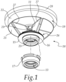
Figure 1 is an exploded view of a support for a bearing according to the invention; -
Figure 2 is a sectional view of an electric pump with a support for a bearing according to the invention; -
Figure 3 is an enlarged-scale view of a detail of the view ofFigure 2 ; -
Figure 4 is an exploded view of the detail ofFigure 3 . - With reference to the figures, a support for a
bearing 12 forelectric pump 50 according to the invention is generally designated by thereference numeral 10. - One of the particularities of the invention resides in that the
support 10 has a contoured portion which forms in a single body: - a
receptacle 11 for abearing 12, - a
receptacle 13 for asealing element 14. - Considering an axis of extension X of the
support 10 as: - the central axis, which lies on the plane of symmetry of the
support 10 - at right angles to the planes of arrangement of the
receptacle 11 for thebearing 12 and of thereceptacle 13 for thesealing element 14, - In this manner, the invention provides a common support for the bearing and the mechanical seal.
- In particular, the
receptacle 13 for thesealing element 14 is arranged inside aflange element 26 which comprises a disk-like portion 15 provided with a first throughhole 25 and a surface from which anannular portion 16 extends which is coaxial to the disk-like portion 15 and surrounds the first throughhole 25. - In the configuration for use, the
sealing element 14, which is constituted by a mechanical seal, is inserted into theannular portion 16 and is seated in the first through hole at/proximate to the disk-like portion 15. - The
support 10 is made of metallic material, such as for example aluminum, and has anelement 17 for covering theannular portion 16, which forms thereceptacle 13 for thesealing element 14. - In particular, the
sealing element 14 is accommodated inside the coveringelement 17 in the first throughhole 25 of theannular portion 16. - The covering
element 17 is made of metallic material, advantageously stainless steel, and is adapted to protect thesupport 10 from water, being arranged at the interface between thewet region 51 of theelectric pump 50 and itsmotor housing 52. - The covering element 17:
- is co-molded with the
flange element 26, - is complementary to the
annular portion 16, - has a shape which duplicates the shape of the
annular portion 16. - In the configuration for use, the
sealing element 14 rests inside the coveringelement 17 and is surrounded by it. - Considering its extension axis X, the
support 10 comprises, at the opposite end with respect to the end provided with thereceptacle 13 for thesealing element 14, atray element 19 which has a circular profile with a flangedperimetric rim 20. - The
tray element 19 comprises abase 21 and aside wall 22 from which theflanged rim 20 is extended. - In particular, the
base 21 is provided with a second throughhole 23 for the insertion of the rotatingshaft 18 of theelectric pump 50. - Inside the
tray element 19 there is atubular portion 24 which is monolithic therewith and constitutes the lateral edge of thereceptacle 11 for thebearing 12. - The inside diameter of the
tubular portion 24 is comparable with the outside diameter of thebearing 12 and is greater than the diameter of the second throughhole 23. - In the configuration for use, the
bearing 12 is inserted in thetubular portion 24 and is substantially in contact with thebase 21 of thetray portion 19. - The
tubular portion 24, thetray element 19, the disk-like portion 15 and theannular portion 16 are coaxial and their axis coincides with the extension axis X of thesupport 10. - In particular, the
flange element 26 and thetray element 19 are connected and joined by one ormore bridge elements 27 which give greater stiffness to thesupport 10. - These
bridge elements 27 have a substantially triangular profile. - Advantageously, the
bridge elements 27 are four, arranged in a radial manner with respect to the extension axis X of thesupport 10 and mutually equidistant. - The presence of four
bridge elements 27 and their distribution with respect to the extension axis X of thesupport 10 give stiffness to the latter. - The first through
hole 25 and the second throughhole 23 form a single passage for the rotatingshaft 18 of theelectric pump 50, around which thebridge elements 27 are arranged. - Considering the extension axis X of the
support 10, thebearing 12 and thesealing element 14 are arranged at opposite ends and are directed toward the outside of thesupport 10, therefore toward opposite sides of thesupport 10. - It should be noted that, with the
support 10, one provides with a single component both a support for a bearing and a support for a sealing element between the wet region and the motor housing. -
Figure 2 shows a cross-section of anelectric pump 50 comprising asupport 10 according to the invention. - The
electric pump 50 has, in the configuration for use, a vertical extension and comprises, from the bottom upward: - a
wet region 51, - a
motor housing 52. - One or
more impellers 54 keyed on therotating shaft 18 are arranged in thewet region 51. - A motor is arranged inside the
motor housing 52 and comprises arotor 55 for the movement of therotating shaft 18, which is keyed thereon, and astator 56 which surrounds therotor 55. - The rotating
shaft 18 is kept in axial alignment by means of two bearings arranged at the ends of therotor 55, respectively: - a first
upper bearing 57, and - a second
lower bearing 12, arranged inside themotor housing 52, proximate to thewet region 51. - The
support 10 for thebearing 12, as described above, is arranged inside theelectric pump 50, at the interface between thewet region 51 and themotor housing 52. - The sealing
element 14 is keyed on therotating shaft 18, at the interface between thewet region 51 and themotor housing 52, and hinders the passage of the liquid from thewet region 51 to themotor housing 52. - In practice it has been found that the invention achieves the intended aim and objects, providing a support for a bearing for electric pump which allows to reduce the number of components of the electric pump.
- The invention provides a common support to the bearing and to the mechanical seal which is completely made of metallic material.
- It should be noted that the invention provides a support for a bearing for electric pump which allows to achieve centering dimensional tolerances with the support for the mechanical seal that are smaller than those achieved by similar supports of a known type, since it is provided monolithically with the support for the mechanical seal and is made of metallic material.
- Furthermore, the invention provides a support for a bearing for electric pump which allows a better coaxiality with the support of the sealing element for the wet region than similar supports of a known type and therefore allows to reduce the bending moments generated on the rotating shaft, since its flange element, which defines the receptacle for the sealing element, and its tubular element, which defines the receptacle for the bearing, are coaxial.
- The invention thus conceived is susceptible of numerous modifications and variations, all of which may be within the scope of the appended claims.
- In practice, the materials used, so long as they are compatible with the specific use, as well as the contingent shapes and dimensions, may be any according to the requirements and the state of the art.
- Where technical features mentioned in any claim are followed by reference signs, those reference signs have been included for the sole purpose of increasing the intelligibility of the claims and accordingly such reference signs do not have any limiting effect on the interpretation of each element identified by way of example by such reference signs.
Claims (11)
- A support (10) for a bearing (12) for an electric pump (50), having a contoured portion which forms in a single body; and comprising:- a receptacle (11) for said bearing (12),- a receptacle (13) for a sealing element (14)said receptacle (13) for said sealing element (14) being arranged within a flange element (26) which comprises:- a disk-like portion (15) provided with a first through hole (25)- an annular portion (16), which is coaxial to said disk-like portion (15) and surrounds said first through hole (25);the support (10) being provided with an element (17) for covering said annular portion (16), which forms said receptacle (13) for said sealing element (14), wherein said covering element (17):- is made of metallic material, preferably stainless steel;- is co-molded with said flange element (26),- is complementary to said annular portion (16),- has a shape which duplicates the shape of said annular portion (16).
- The support (10) according to claim 1, characterized in that it is made of metallic material.
- The support (10) according to claim 1, characterized in that said receptacle (11) for said bearing (12) and said receptacle (13) for said sealing element (14) are arranged at two opposite ends of said support (10) along its axis of extension (X), considering said axis of extension (X) as:- a central axis, which lies on the plane of symmetry of said support (10),- at right angles to the planes of arrangement of said receptacle (11) for said bearing (12) and of said receptacle (13) for said sealing element (14).
- The support (10) according to claim 3, characterized in that, considering said axis of extension (X), it comprises a tray element (19) which has a circular profile, at the opposite end with respect to the end provided with said receptacle (13) for said sealing element (14).
- The support (10) according to claim 4, characterized in that said tray element (19) comprises a base (21) and a side wall (22), said base (21) being provided with a second through hole (23).
- The support (10) according to claim 4, characterized in that inside said tray element (19) there is a tubular portion (24) which is monolithic therewith, said tubular portion (24) constituting the lateral edge of said receptacle (11) for said bearing (12).
- The support (10) according to claim 6, characterized in that the inside diameter of said tubular portion (24) is larger than the diameter of said second through hole (23).
- The support (10) according to claim 6, characterized in that said tubular portion (24), said tray element (19), said disk-like portion (15) and said annular portion (16) are coaxial and their axis coincides with said axis of extension (X) of said support (10).
- The support (10) according to claim 4, characterized in that said flange element (26) and said tray element (19) are connected and joined by one or more bridge elements (27).
- The support (10) according to claim 9, characterized in that said one or more bridge elements (27) have a substantially triangular profile and are arranged radially with respect to said axis of extension (X) of said support (10).
- An electric pump (50), comprising:- a wet region (51), one or more impellers (54) keyed on a rotating shaft (18) being arranged in said wet region,- a motor housing (52),- a motor arranged inside said motor housing (52), said motor comprising a rotor (55) for the movement of said rotating shaft (18), which is keyed thereon, and a stator (56) which surrounds said rotor (55),said rotating shaft (18) being kept in axial alignment by means of two bearings arranged at the ends of said rotor (55):- a first bearing (57),- a second bearing (12), arranged inside said motor housing (52), proximate to said wet region (51),characterized in that it comprises, at the interface between said wet region (51) and said motor housing (52), a support (10) for the support of said second bearing (12) according to one or more of the preceding claims.
Applications Claiming Priority (1)
| Application Number | Priority Date | Filing Date | Title |
|---|---|---|---|
| IT102020000004873A IT202000004873A1 (en) | 2020-03-09 | 2020-03-09 | PERFECTED SUPPORT FOR BEARING FOR ELECTRIC PUMP AND ELECTRIC PUMP WITH A SIMILAR SUPPORT |
Publications (3)
| Publication Number | Publication Date |
|---|---|
| EP3879121A1 EP3879121A1 (en) | 2021-09-15 |
| EP3879121B1 true EP3879121B1 (en) | 2023-07-26 |
| EP3879121C0 EP3879121C0 (en) | 2023-07-26 |
Family
ID=70804923
Family Applications (1)
| Application Number | Title | Priority Date | Filing Date |
|---|---|---|---|
| EP21152603.3A Active EP3879121B1 (en) | 2020-03-09 | 2021-01-20 | Support for a bearing for electric pump and electric pump with such support |
Country Status (4)
| Country | Link |
|---|---|
| EP (1) | EP3879121B1 (en) |
| CN (1) | CN113374726A (en) |
| ES (1) | ES2953315T3 (en) |
| IT (1) | IT202000004873A1 (en) |
Family Cites Families (5)
| Publication number | Priority date | Publication date | Assignee | Title |
|---|---|---|---|---|
| JP3587544B2 (en) * | 1993-08-31 | 2004-11-10 | 株式会社佐山製作所 | Land pump |
| JP2000045981A (en) * | 1998-07-29 | 2000-02-15 | Teral Kyokuto Inc | Land pump |
| ITPD20120284A1 (en) * | 2012-10-02 | 2014-04-03 | Dab Pumps Spa | PERFECT CENTRIFUGAL ELECTRIC PUMP STRUCTURE |
| IT201600089875A1 (en) * | 2016-09-06 | 2018-03-06 | Calpeda A Spa | CENTRIFUGAL ELECTRIC PUMP WITH INTERMEDIATE CHAMBER, PARTICULARLY SUITABLE FOR THE PUMPING OF LIQUIDS CONTAINING SOLID IMPURITIES |
| CN106989031A (en) * | 2017-05-23 | 2017-07-28 | 六安海泉泵业有限公司 | A kind of novel submersible pollution discharge pump |
-
2020
- 2020-03-09 IT IT102020000004873A patent/IT202000004873A1/en unknown
-
2021
- 2021-01-20 ES ES21152603T patent/ES2953315T3/en active Active
- 2021-01-20 EP EP21152603.3A patent/EP3879121B1/en active Active
- 2021-03-05 CN CN202110243003.8A patent/CN113374726A/en active Pending
Also Published As
| Publication number | Publication date |
|---|---|
| CN113374726A (en) | 2021-09-10 |
| ES2953315T3 (en) | 2023-11-10 |
| EP3879121C0 (en) | 2023-07-26 |
| IT202000004873A1 (en) | 2021-09-09 |
| EP3879121A1 (en) | 2021-09-15 |
Similar Documents
| Publication | Publication Date | Title |
|---|---|---|
| US7131823B2 (en) | Electrically driven pump and domestic appliance having the pump | |
| US20090081036A1 (en) | Axial flow fan | |
| US7261524B2 (en) | Rotation support with improved thrust-bearing for rotors of pump electric motors | |
| JP5259164B2 (en) | Blower impeller | |
| US20070189892A1 (en) | Axial flow fan and housing for the same | |
| JP2006029241A (en) | Centrifugal pump | |
| CN109958635B (en) | Centrifugal fan | |
| JP2013204784A (en) | Bearing device and blast fan | |
| CN1869452B (en) | Pump | |
| US10570903B2 (en) | Centrifugal pump | |
| EP3879121B1 (en) | Support for a bearing for electric pump and electric pump with such support | |
| CN110159544A (en) | Pump installation | |
| US10156238B2 (en) | Centrifugal pump | |
| CN105090054B (en) | Centrifugal pump | |
| JP2007205360A (en) | Centrifugal pump | |
| KR20000052358A (en) | Drain pump | |
| JP2017505402A (en) | Electric vehicle refrigerant pump | |
| KR20210007929A (en) | Fan Motor and Manufacturing the Same | |
| CN102575680A (en) | Submerged centrifugal electric pump | |
| US2862452A (en) | Pumps | |
| US20110014073A1 (en) | Turbo-molecular pump | |
| JP5977693B2 (en) | Impeller and water pump | |
| US20100232967A1 (en) | Centrifugal fan | |
| CN110017283B (en) | Pump assembly with a gap sleeve and coupling between a rotor and a gap sleeve | |
| EP0962264A2 (en) | Compact vacuum pump |
Legal Events
| Date | Code | Title | Description |
|---|---|---|---|
| PUAI | Public reference made under article 153(3) epc to a published international application that has entered the european phase |
Free format text: ORIGINAL CODE: 0009012 |
|
| STAA | Information on the status of an ep patent application or granted ep patent |
Free format text: STATUS: THE APPLICATION HAS BEEN PUBLISHED |
|
| AK | Designated contracting states |
Kind code of ref document: A1 Designated state(s): AL AT BE BG CH CY CZ DE DK EE ES FI FR GB GR HR HU IE IS IT LI LT LU LV MC MK MT NL NO PL PT RO RS SE SI SK SM TR |
|
| STAA | Information on the status of an ep patent application or granted ep patent |
Free format text: STATUS: REQUEST FOR EXAMINATION WAS MADE |
|
| 17P | Request for examination filed |
Effective date: 20220301 |
|
| RBV | Designated contracting states (corrected) |
Designated state(s): AL AT BE BG CH CY CZ DE DK EE ES FI FR GB GR HR HU IE IS IT LI LT LU LV MC MK MT NL NO PL PT RO RS SE SI SK SM TR |
|
| GRAP | Despatch of communication of intention to grant a patent |
Free format text: ORIGINAL CODE: EPIDOSNIGR1 |
|
| STAA | Information on the status of an ep patent application or granted ep patent |
Free format text: STATUS: GRANT OF PATENT IS INTENDED |
|
| INTG | Intention to grant announced |
Effective date: 20230504 |
|
| GRAS | Grant fee paid |
Free format text: ORIGINAL CODE: EPIDOSNIGR3 |
|
| P01 | Opt-out of the competence of the unified patent court (upc) registered |
Effective date: 20230515 |
|
| GRAA | (expected) grant |
Free format text: ORIGINAL CODE: 0009210 |
|
| STAA | Information on the status of an ep patent application or granted ep patent |
Free format text: STATUS: THE PATENT HAS BEEN GRANTED |
|
| AK | Designated contracting states |
Kind code of ref document: B1 Designated state(s): AL AT BE BG CH CY CZ DE DK EE ES FI FR GB GR HR HU IE IS IT LI LT LU LV MC MK MT NL NO PL PT RO RS SE SI SK SM TR |
|
| REG | Reference to a national code |
Ref country code: CH Ref legal event code: EP |
|
| REG | Reference to a national code |
Ref country code: DE Ref legal event code: R096 Ref document number: 602021003655 Country of ref document: DE |
|
| REG | Reference to a national code |
Ref country code: IE Ref legal event code: FG4D |
|
| U01 | Request for unitary effect filed |
Effective date: 20230809 |
|
| U07 | Unitary effect registered |
Designated state(s): AT BE BG DE DK EE FI FR IT LT LU LV MT NL PT SE SI Effective date: 20230816 |
|
| P04 | Withdrawal of opt-out of the competence of the unified patent court (upc) registered |
Effective date: 20230811 |
|
| REG | Reference to a national code |
Ref country code: LT Ref legal event code: MG9D Ref country code: ES Ref legal event code: FG2A Ref document number: 2953315 Country of ref document: ES Kind code of ref document: T3 Effective date: 20231110 |
|
| PG25 | Lapsed in a contracting state [announced via postgrant information from national office to epo] |
Ref country code: GR Free format text: LAPSE BECAUSE OF FAILURE TO SUBMIT A TRANSLATION OF THE DESCRIPTION OR TO PAY THE FEE WITHIN THE PRESCRIBED TIME-LIMIT Effective date: 20231027 |
|
| PG25 | Lapsed in a contracting state [announced via postgrant information from national office to epo] |
Ref country code: IS Free format text: LAPSE BECAUSE OF FAILURE TO SUBMIT A TRANSLATION OF THE DESCRIPTION OR TO PAY THE FEE WITHIN THE PRESCRIBED TIME-LIMIT Effective date: 20231126 |
|
| PG25 | Lapsed in a contracting state [announced via postgrant information from national office to epo] |
Ref country code: RS Free format text: LAPSE BECAUSE OF FAILURE TO SUBMIT A TRANSLATION OF THE DESCRIPTION OR TO PAY THE FEE WITHIN THE PRESCRIBED TIME-LIMIT Effective date: 20230726 Ref country code: NO Free format text: LAPSE BECAUSE OF FAILURE TO SUBMIT A TRANSLATION OF THE DESCRIPTION OR TO PAY THE FEE WITHIN THE PRESCRIBED TIME-LIMIT Effective date: 20231026 Ref country code: IS Free format text: LAPSE BECAUSE OF FAILURE TO SUBMIT A TRANSLATION OF THE DESCRIPTION OR TO PAY THE FEE WITHIN THE PRESCRIBED TIME-LIMIT Effective date: 20231126 Ref country code: HR Free format text: LAPSE BECAUSE OF FAILURE TO SUBMIT A TRANSLATION OF THE DESCRIPTION OR TO PAY THE FEE WITHIN THE PRESCRIBED TIME-LIMIT Effective date: 20230726 Ref country code: GR Free format text: LAPSE BECAUSE OF FAILURE TO SUBMIT A TRANSLATION OF THE DESCRIPTION OR TO PAY THE FEE WITHIN THE PRESCRIBED TIME-LIMIT Effective date: 20231027 |
|
| U20 | Renewal fee paid [unitary effect] |
Year of fee payment: 4 Effective date: 20240109 |
|
| PG25 | Lapsed in a contracting state [announced via postgrant information from national office to epo] |
Ref country code: PL Free format text: LAPSE BECAUSE OF FAILURE TO SUBMIT A TRANSLATION OF THE DESCRIPTION OR TO PAY THE FEE WITHIN THE PRESCRIBED TIME-LIMIT Effective date: 20230726 |
|
| PG25 | Lapsed in a contracting state [announced via postgrant information from national office to epo] |
Ref country code: SM Free format text: LAPSE BECAUSE OF FAILURE TO SUBMIT A TRANSLATION OF THE DESCRIPTION OR TO PAY THE FEE WITHIN THE PRESCRIBED TIME-LIMIT Effective date: 20230726 Ref country code: RO Free format text: LAPSE BECAUSE OF FAILURE TO SUBMIT A TRANSLATION OF THE DESCRIPTION OR TO PAY THE FEE WITHIN THE PRESCRIBED TIME-LIMIT Effective date: 20230726 Ref country code: CZ Free format text: LAPSE BECAUSE OF FAILURE TO SUBMIT A TRANSLATION OF THE DESCRIPTION OR TO PAY THE FEE WITHIN THE PRESCRIBED TIME-LIMIT Effective date: 20230726 Ref country code: SK Free format text: LAPSE BECAUSE OF FAILURE TO SUBMIT A TRANSLATION OF THE DESCRIPTION OR TO PAY THE FEE WITHIN THE PRESCRIBED TIME-LIMIT Effective date: 20230726 |