JP5259164B2 - Blower impeller - Google Patents
Blower impeller Download PDFInfo
- Publication number
- JP5259164B2 JP5259164B2 JP2007313843A JP2007313843A JP5259164B2 JP 5259164 B2 JP5259164 B2 JP 5259164B2 JP 2007313843 A JP2007313843 A JP 2007313843A JP 2007313843 A JP2007313843 A JP 2007313843A JP 5259164 B2 JP5259164 B2 JP 5259164B2
- Authority
- JP
- Japan
- Prior art keywords
- balance
- hub
- impeller
- pockets
- Prior art date
- Legal status (The legal status is an assumption and is not a legal conclusion. Google has not performed a legal analysis and makes no representation as to the accuracy of the status listed.)
- Expired - Fee Related
Links
- 238000002347 injection Methods 0.000 claims description 3
- 239000007924 injection Substances 0.000 claims description 3
- 230000002093 peripheral effect Effects 0.000 claims 2
- 238000000034 method Methods 0.000 description 3
- 238000002485 combustion reaction Methods 0.000 description 2
- 239000000470 constituent Substances 0.000 description 2
- 239000000463 material Substances 0.000 description 2
- 238000005266 casting Methods 0.000 description 1
- 230000008878 coupling Effects 0.000 description 1
- 238000010168 coupling process Methods 0.000 description 1
- 238000005859 coupling reaction Methods 0.000 description 1
- 230000001771 impaired effect Effects 0.000 description 1
- 238000009434 installation Methods 0.000 description 1
- 238000007493 shaping process Methods 0.000 description 1
- 239000000243 solution Substances 0.000 description 1
Images


Classifications
-
- F—MECHANICAL ENGINEERING; LIGHTING; HEATING; WEAPONS; BLASTING
- F04—POSITIVE - DISPLACEMENT MACHINES FOR LIQUIDS; PUMPS FOR LIQUIDS OR ELASTIC FLUIDS
- F04D—NON-POSITIVE-DISPLACEMENT PUMPS
- F04D29/00—Details, component parts, or accessories
- F04D29/26—Rotors specially for elastic fluids
- F04D29/28—Rotors specially for elastic fluids for centrifugal or helico-centrifugal pumps for radial-flow or helico-centrifugal pumps
- F04D29/281—Rotors specially for elastic fluids for centrifugal or helico-centrifugal pumps for radial-flow or helico-centrifugal pumps for fans or blowers
-
- F—MECHANICAL ENGINEERING; LIGHTING; HEATING; WEAPONS; BLASTING
- F04—POSITIVE - DISPLACEMENT MACHINES FOR LIQUIDS; PUMPS FOR LIQUIDS OR ELASTIC FLUIDS
- F04D—NON-POSITIVE-DISPLACEMENT PUMPS
- F04D29/00—Details, component parts, or accessories
- F04D29/66—Combating cavitation, whirls, noise, vibration or the like; Balancing
- F04D29/661—Combating cavitation, whirls, noise, vibration or the like; Balancing especially adapted for elastic fluid pumps
- F04D29/662—Balancing of rotors
Landscapes
- Engineering & Computer Science (AREA)
- Mechanical Engineering (AREA)
- General Engineering & Computer Science (AREA)
- Structures Of Non-Positive Displacement Pumps (AREA)
Description
本発明は、請求項1又は3の前提部(プリアンブル部)に記載されている送風機の羽根車に関する。このような種類の羽根車は、ドイツ特許出願公開公報第DE4136293A1号(特許文献1)に記載されている。 The present invention relates to an impeller for a blower described in the premise part (preamble part) of claim 1 or 3. Such kind of impeller is described in German Patent Application Publication No. DE 4136293A1 (Patent Document 1).
ドイツ特許出願公開公報第DE4136293A1号は、二つの案内板の間に配置されたファンブレードと、駆動モータのロータに羽根車を取り付けるために案内板の領域に配置されたハブとを備える、送風機の羽根車を開示している。羽根車の両方の案内板には、バランス部材を挿入するためのポケットが設けられている。これらのポケットは、軸方向においてそれぞれ同じ側に向って、又は、それぞれ反対の側に向って開いている。それぞれの案内板が異なる直径を有する場合、それぞれのポケットも異なる直径を有する。ドイツ特許出願公開公報第DE4136293A1号に記載の羽根車は、低コストに製造することができ、容易にバランスを正すことができる。 DE 4136293 A1 discloses a fan impeller comprising a fan blade arranged between two guide plates and a hub arranged in the region of the guide plate for attaching the impeller to the rotor of a drive motor. Is disclosed. Both guide plates of the impeller are provided with pockets for inserting balance members. These pockets are open toward the same side in the axial direction or toward opposite sides. If each guide plate has a different diameter, each pocket also has a different diameter. The impeller described in German Patent Application Publication No. DE 4136293A1 can be manufactured at a low cost and can easily be balanced.
米国特許公報第US6,168,734B1号(特許文献2)には、吸込リングの半径方向の厚さが所定の部位で増加させられる、遠心ファンのバランスを正す方法が記載されており、この目的のために、調整可能なリングを備える鋳型が使用される。 US Pat. No. 6,168,734 B1 describes a method for correcting the centrifugal fan balance in which the radial thickness of the suction ring is increased at a predetermined site. For this purpose, a mold with an adjustable ring is used.
本発明は、原則として送風機の羽根車、特にラジアルファンの羽根車に適用可能である。このような送風機の羽根車は、通常、一つ又は複数の支持リングを含んでおり、これらの間にファンブレードが配置されており、一つ又は複数の支持リングの領域には、駆動モータのロータに羽根車を取り付けるためのハブが配置されている。ラジアルファンの場合、空気は吸込口によって羽根車の中心部で吸い込まれ、ファンブレードを通って半径方向に再び吹き出される。羽根車の直径が大きい場合だけでなく、3000乃至4000回転/分の範囲内にある、あるいは最大7000回転/分にまで達する比較的高い回転数によっても、羽根車(インペラ)は騒音を低減するために、及び、組み付けられている軸受の耐用寿命を延ばすために、バランスを正しく保たれなくてはならない。このことは従来の技術では、上述した通り、対応するポケットへのバランス部材の挿入又はバランス部材の取付によって行われ、あるいは、材料の剥離によっても行われる。前掲の米国特許のように、鋳造中に羽根車を特別に成形することによってもバランスを正すことができるが、これは比較的高いコストを要する。そこで現実問題としては、バランスクランプ、バランスクリップ、又は、バランスキット等を用いて、成形が完成した羽根車のバランスを正す方法が好まれている。こうしたバランス部材は、そのために設けられた「バランスポケット」に入れられるか、又は、例えばファンブレードや支持リングといった適当な成形部品に取り付けることができる。ドイツ特許出願公開公報第DE4136293A1号に記載されているように、これは軸方向にオフセットされた二つのバランス平面で行われることが多い。 The present invention is in principle applicable to an impeller of a blower, in particular, an impeller of a radial fan. Such an impeller of a blower usually includes one or a plurality of support rings, between which fan blades are disposed, and in the region of the one or more support rings, a drive motor is provided. A hub for mounting the impeller on the rotor is arranged. In the case of a radial fan, air is sucked in at the center of the impeller by a suction port and blown out again in the radial direction through the fan blade. Impellers reduce noise not only when the impeller diameter is large, but also by relatively high speeds in the range of 3000 to 4000 revolutions / minute, or even up to 7000 revolutions / minute. Therefore, and in order to extend the service life of the assembled bearings, the balance must be maintained correctly. In the prior art, as described above, this is performed by inserting the balance member into the corresponding pocket or attaching the balance member, or by peeling the material. The balance can also be corrected by specially shaping the impeller during casting, as in the above-mentioned US patent, but this is relatively expensive. Therefore, as a practical problem, a method of correcting the balance of an impeller that has been molded using a balance clamp, a balance clip, a balance kit, or the like is preferred. Such a balance member can be placed in a “balance pocket” provided therefor or attached to a suitable molded part, for example a fan blade or a support ring. This is often done with two balance planes offset in the axial direction, as described in DE 4136293 A1.
ドイツ特許出願公開公報第DE4136293A1号を含めた従来の技術の解決法は、バランス部材が送風機の空気貫流領域に配置され、又は、そのすぐ近傍に配置されるという欠点をしばしば有する。そのために、バランス部材自体によってばかりでなく、場合により空のバランスポケットによっても、妨害的な流動騒音が発生させられる可能性がある。
そこで、本発明の課題は、動作時にバランス部材又はバランスポケットによって妨害的な流動騒音を発生させることなく、簡単な方法でバランスを正すことができる送風機の羽根車を提供することである。 Therefore, an object of the present invention is to provide an impeller of a blower that can correct the balance by a simple method without generating disturbing flow noise by a balance member or a balance pocket during operation.
この課題は、請求項1の構成要件を備える羽根車によって、又は、請求項3の構成要件を備える羽根車によって解決される。 This problem is solved by an impeller having the constituent elements of claim 1 or by an impeller having the constituent elements of claim 3.
本発明は、駆動モータのロータに羽根車を連結するためのハブと、ハブに配置されたファンブレードとを含む送風機、特にラジアルファンの羽根車を意図している。ファンブレードは、羽根車によって生成される空気流の流動経路を規定する。本発明によると、バランス部材を挿入するためのバランスポケットは、羽根車によって生成される空気流の流動経路の範囲外に設けられており、これらのバランスポケットは、特に羽根車のハブに配置されている。特にラジアルファンの場合、ハブの領域には、空気流にとってさほど重要でない領域が生じる。しかも通常の場合、空気が貫流する羽根車の断面積を低減したり、その他の形で影響を及ぼしたりすることなく、ハブにバランスポケットを設置するだけの十分なスペースがここにはある。即ち、本発明は、バランス部材を収容するためのバランスポケットの設置位置について、物理的に適した位置を見出したのであり、即ち、羽根車のバランス補正を有効に行うことができ、流動技術的・騒音技術的に重大でない領域にある位置を見出したのである。 The present invention contemplates a blower, particularly a radial fan impeller, including a hub for coupling the impeller to the rotor of the drive motor and fan blades disposed on the hub. The fan blades define the flow path of the air flow generated by the impeller. According to the invention, the balance pockets for inserting the balance members are provided outside the flow path of the air flow generated by the impeller, and these balance pockets are arranged in particular on the hub of the impeller. ing. Particularly in the case of radial fans, there are areas in the hub area that are not very important for the air flow. Moreover, there is usually enough space here to install a balance pocket on the hub without reducing the cross-sectional area of the impeller through which air flows or otherwise affecting it. That is, the present invention has found a physically suitable position for the installation position of the balance pocket for accommodating the balance member, that is, the balance correction of the impeller can be effectively performed, and the flow technical・ We found a position in a non-technical area.
各バランスポケットは、ハブの外側円周に配置され、軸方向において同じ側に向って開いているのが好ましく、それにより、バランスポケットに問題なくバランス部材を装備することができる。 Each balance pocket is preferably arranged on the outer circumference of the hub and open towards the same side in the axial direction, so that the balance pocket can be equipped with a balance member without any problems.
各バランスポケットは、軸方向において二つの平面に、互いに同心的に異なる半径でハブに位置しているのが格別に好ましい。このことは、特別に好ましい本発明の実施の形態では、ハブに段部が構成されており、バランスポケットの二つの群が規定され、そのうち一方の群はハブの円周壁の端面に刻設されており、他方の群はこれに対応する段部の端面に刻設されていることによって、実現される。それにより、羽根車の裏面にある空気流にとって重大でない領域を、バランス部材を格納するために有効に活用することができる。 It is particularly preferred that each balance pocket is located on the hub in two axial planes with concentrically different radii. This is because, in a particularly preferred embodiment of the present invention, the hub is configured with a step, and two groups of balance pockets are defined, one of which is engraved on the end face of the circumferential wall of the hub. The other group is realized by being engraved on the end face of the corresponding stepped portion. Thereby, an area that is not critical to the air flow on the back of the impeller can be effectively utilized to store the balance member.
本発明は、軸流ファンや斜流ファンでも適用可能である。その場合にも空気には、若干回転することによって遠心力を受ける半径方向の流れが生じるからである。特に斜流形羽根車は、その円錐状の設計形態によって、本発明に非常に適している。 The present invention is also applicable to an axial flow fan and a mixed flow fan. This is also because the air in this case has a radial flow that receives centrifugal force by rotating slightly. Particularly, the mixed flow type impeller is very suitable for the present invention due to its conical design.
本発明による羽根車は、ハブとファンブレードとを含み、バランスポケットが直接一体成型されているプラスチック射出成形品として構成されているのが好ましい。 The impeller according to the present invention is preferably configured as a plastic injection-molded product including a hub and a fan blade and having a balance pocket directly integrally formed.
本発明は、上述した種類の羽根車を備える送風機も含んでおり、駆動モータは、ハブの中心部に配置されるのが好ましい。 The invention also includes a blower comprising an impeller of the type described above, and the drive motor is preferably located at the center of the hub.
次に、図面を参照しながら有利な実施の形態を用いて本発明を詳しく説明する。 Next, the present invention will be described in detail using advantageous embodiments with reference to the drawings.
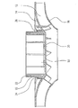
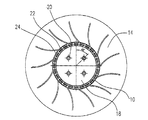
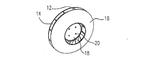
図1、図2及び図3は、ラジアルファン用として設計された本発明に係る羽根車の実施の形態の断面図、平面図及び斜視図を示している。この羽根車は、ハブ10を含んでおり、かつ、案内板14を介してハブ10と連結されたファンブレード12を含んでいる。ファンブレード12は、ハブ10及び案内板14と反対を向いている方の側において、送風機の動作時に羽根車と一緒に回転するカバー16と連結されている。但し、本発明は、一緒に回転するカバー16を有していない羽根車をも対象としており、その場合、送風機は、送風機ハウジングがカバーを形成するように構成されていてもよい。
1, 2 and 3 show a sectional view, a plan view and a perspective view of an embodiment of an impeller according to the present invention designed for a radial fan. This impeller includes a
図示した実施の形態では、ハブ10は、閉じた底面18を有し、その上に、羽根車の中心部に駆動モータを取り付けるためのピン20が設けられている。
In the illustrated embodiment, the
図1及び図2に見られるように、ハブ10の領域には、バランス部材を収容するための二つの群のバランスポケット22、24が形成されている。本発明の好ましい実施の形態では、バランスポケット22、24を互いに同心的に異なる半径でハブに形成するために、ハブ10は、段部26を有する。二つの群のうち一方の群のバランスポケット22は、ハブ10の円周壁の端面に刻設されており、他方の群のバランスポケット24は、段部26の対応する端面に刻設されている。即ち、バランスポケット22、24は、軸方向において二つの平面に、ハブ10の円周に沿って異なる半径で位置している。それにより、羽根車のバランスを正すにあたって、バランス部材の配置に関して特別な自由度が得られる。
As can be seen in FIGS. 1 and 2, two groups of
本発明の好ましい実施の形態では、バランスポケット22、24は、羽根車の同じ側からそれぞれアクセス可能であり、それにより、バランスポケットへのバランス部材の格納が格別に容易になる。本発明によると、バランスポケットは、羽根車によって生成される空気流の流動経路の範囲外に位置しているので、羽根車の空気通過のための断面積を損なうことがなく、また、空のバランスポケットによる騒音が生じることもない。
In a preferred embodiment of the present invention, the
バランスポケット22、24は、ハブ10の射出成形の際に形成されるのが好ましい。ハブの領域にバランスポケットを設けることは、空気流動にとってハブは重要ではない領域であるという理由から、格別に好ましい。本発明に基づくハブへのバランスポケットの配置によって、騒音発生の要因を内包していない、格別に簡素で組立の容易な羽根車の構造が得られる。
The
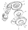
図4及び図5は、本発明に係る羽根車を適用することができる、燃焼システムのための送風機の断面図及び斜視分解図を示している。これらの図面は、本発明に係る羽根車の利用例を説明する役目を果すものに過ぎず、これ以外の用途も本発明の範疇に含まれる。 4 and 5 show a cross-sectional view and a perspective exploded view of a blower for a combustion system to which an impeller according to the present invention can be applied. These drawings only serve to explain the usage example of the impeller according to the present invention, and other uses are also included in the scope of the present invention.
この送風機は、二つのハウジング半体32、34が組み合わせられてなる、螺旋形をした送風機ハウジングを含む。送風機ハウジングの内部には、本発明に係る羽根車36があり、その中心部に電気駆動モータ38が配置されている。モータ38は、ブラシレス直流モータ又はその他の永久磁石モータであってよい。モータ38は、アウターロータ型モータ又はインナーロータ型モータ又はディスクロータモータとして構成されていてよく、モータの構造は本発明の対象ではない。図示した実施の形態では、モータ38は、ハウジング半体34の側に配置されている。これと対向するハウジング半体32の側には、流入ノズル50を備える空気吸込口48が設けられている。
This blower includes a spiral blower housing in which two
図示した実施の形態では、送風機ハウジングは、ベンチュリユニット56を接続するために用いられる接続管54と連結された空気出口52を有するように構成されている。ベンチュリユニット56はベンチュリ混合管とガス入口とを含むが、ベンチュリユニット56の詳細は本発明の対象ではない。ベンチュリユニット56は、例えば(図示しない)バーナに取り付けることができる。
In the illustrated embodiment, the blower housing is configured to have an
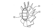
図6、図7及び図8は、斜流ファン用として設計された本発明に係る羽根車の別の実施の形態の斜視図、断面図及び平面図をそれぞれ示している。この羽根車はハブ60を含んでおり、かつ、案内テーパ部64を介してハブ60と連結されたファンブレード62を含んでいる。図示した実施の形態では、ハブ60は、閉じた底面68を有し、それによってハブ60の内部には、羽根車の中心部に駆動モータを収容するための空間が形成されている。
6, 7 and 8 show a perspective view, a sectional view and a plan view, respectively, of another embodiment of an impeller according to the present invention designed for a mixed flow fan. The impeller includes a
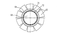
図7及び図8を見ると判るように、ハブ60の領域には、バランス部材を収容するための二つの群のバランスポケット72、74が形成されている。本発明の好ましい実施の形態では、ハブ60は、バランスポケット72、74を互いに同心的にハブの異なる半径で形成するために段部76を有する。第1の実施の形態と同様に、二つの群のうち一方の群のバランスポケット72はハブ60の円周壁の端面に刻設されており、他方の群のバランスポケット74は段部76の対応する端面に刻設されている。バランスポケット72、74については、第1の実施の形態に関して上に述べたことが当てはまる。
As can be seen from FIGS. 7 and 8, two groups of balance pockets 72, 74 are formed in the region of the
送風機ハウジング及び羽根車はプラスチック材料でできているのが好ましく、複数のプラスチック射出成形品で製作されているのが特別に好ましい。それにより、質量が小さく低コストの構成が得られる。 The blower housing and the impeller are preferably made of a plastic material, particularly preferably made of a plurality of plastic injection molded articles. Thereby, a low-cost configuration with a small mass can be obtained.
以上の説明、図面及び略図に開示されている構成要件は、単独でも任意の組み合わせの形態でも、本発明を様々な実施の形態で具体化するために有意義であり得る。 The features disclosed in the above description, drawings, and schematics may be significant for embodying the present invention in various embodiments, either alone or in any combination.
10 ハブ
12 ファンブレード
14 案内板
16 カバー
18 底面
20 ピン
22、24 バランスポケット
26 段部
32、34 ハウジング半体
36 羽根車
38 駆動モータ
48 空気吸込口
50 流入ノズル
52 空気出口
54 接続管
56 ベンチュリユニット
60 ハブ
62 ファンブレード
64 案内テーパ部
68 底面
72、74 バランスポケット
76 段部
DESCRIPTION OF
Claims (5)
駆動モータと前記羽根車(36)とを連結するためのハブ(10)と、
前記ハブ(10)に配置されたファンブレード(12)であって、前記羽根車(36)によって生成される空気流の流動経路を規定するファンブレード(12)と、
バランス部材を挿入するためのバランスポケット(22、24)と、
を備え、
前記バランスポケット(22、24)は、前記羽根車(36)によって生成される空気流の流動経路の範囲外に設けられており、
前記ハブ(10)の外周側に段部(26)が形成されており、二つの群の前記バランスポケット(22、24)が、互いに同心的に異なる半径で前記ハブ(10)に形成されており、
前記二つの群のバランスポケットのうちの一方の群のバランスポケット(22)は、前記ハブ(10)の円周壁の端面に刻設されており、他方の群のバランスポケット(24)は、前記段部(26)の対応する端面に刻設されており、
前記一方の群のバランスポケット(22)のそれぞれは、前記ハブの同じ径方向に配置される前記他方の群の中の一つのバランスポケット(24)に対応づけて設けられることを特徴とする羽根車。 In blowers, especially radial fan impellers (36),
A hub (10) for connecting a drive motor and the impeller (36);
A fan blade (12) disposed in the hub (10), the fan blade (12) defining a flow path of an air flow generated by the impeller (36);
Balance pockets (22, 24) for inserting balance members;
With
The balance pockets (22, 24) are provided outside the range of the flow path of the air flow generated by the impeller (36),
A step portion (26) is formed on the outer peripheral side of the hub (10), and two groups of the balance pockets (22, 24) are formed on the hub (10) with different concentric radii. And
The balance pocket (22) of one group of the balance pockets of the two groups is carved on the end face of the circumferential wall of the hub (10), and the balance pocket (24) of the other group is Engraved on the corresponding end face of the step (26) ,
Each of the balance pockets (22) of the one group is provided in association with one balance pocket (24) in the other group arranged in the same radial direction of the hub. car.
駆動モータと前記羽根車(36)とを連結するためのハブ(10)と、
バランス部材を挿入するためのバランスポケット(22、24)と、
を備え、
前記バランスポケット(22、24)は、前記羽根車(36)によって生成される空気流の流動経路の範囲外に設けられており、
前記ハブ(10)の外周側に段部(26)が形成されており、二つの群の前記バランスポケット(22、24)が、互いに同心的に異なる半径で前記ハブ(10)に形成されており、
前記二つの群のバランスポケットのうちの一方の群のバランスポケット(22)は、前記ハブ(10)の円周壁の端面に刻設されており、他方の群のバランスポケット(24)は、前記段部(26)の対応する端面に刻設されていることを特徴とする羽根車。 In blowers, especially radial fan impellers (36),
A hub (10) for connecting a drive motor and the impeller (36);
Balance pockets (22, 24) for inserting balance members;
With
The balance pockets (22, 24) are provided outside the range of the flow path of the air flow generated by the impeller (36),
A step portion (26) is formed on the outer peripheral side of the hub (10), and two groups of the balance pockets (22, 24) are formed on the hub (10) with different concentric radii. And
The balance pocket (22) of one group of the balance pockets of the two groups is carved on the end face of the circumferential wall of the hub (10), and the balance pocket (24) of the other group is An impeller characterized in that it is engraved on the corresponding end face of the step (26).
Applications Claiming Priority (2)
| Application Number | Priority Date | Filing Date | Title |
|---|---|---|---|
| DE200610057087 DE102006057087B3 (en) | 2006-12-04 | 2006-12-04 | Injection-molded plastic rotor for radial blower, is produced with integral hub including concentric recesses for balancing weights at differing axial and radial positions |
| DE102006057087.1 | 2006-12-04 |
Publications (2)
| Publication Number | Publication Date |
|---|---|
| JP2008138684A JP2008138684A (en) | 2008-06-19 |
| JP5259164B2 true JP5259164B2 (en) | 2013-08-07 |
Family
ID=39400015
Family Applications (1)
| Application Number | Title | Priority Date | Filing Date |
|---|---|---|---|
| JP2007313843A Expired - Fee Related JP5259164B2 (en) | 2006-12-04 | 2007-12-04 | Blower impeller |
Country Status (2)
| Country | Link |
|---|---|
| JP (1) | JP5259164B2 (en) |
| DE (1) | DE102006057087B3 (en) |
Families Citing this family (14)
| Publication number | Priority date | Publication date | Assignee | Title |
|---|---|---|---|---|
| DE102009028130A1 (en) * | 2009-07-30 | 2011-02-03 | Robert Bosch Gmbh | Guide geometry for semi-axial fan wheels |
| WO2011038884A1 (en) * | 2009-10-03 | 2011-04-07 | Ebm-Papst St. Georgen Gmbh & Co. Kg | Cross-flow fan |
| JP5717046B2 (en) * | 2010-11-12 | 2015-05-13 | 日本電産株式会社 | Blower fan |
| DE202010015749U1 (en) | 2010-11-14 | 2012-02-15 | Ebm-Papst St. Georgen Gmbh & Co. Kg | Diagonal fan |
| DE102011000208A1 (en) * | 2011-01-19 | 2012-07-19 | Minebea Co., Ltd. | Blade wheel for fan i.e. radial fan, has hub for connecting wheel with drive motor, fan blades arranged around hub, and pockets provided for inserting balancing weights and arranged partially in all fan blades or in selected fan blades |
| WO2013053387A1 (en) | 2011-10-12 | 2013-04-18 | Ebm-Papst Mulfingen Gmbh & Co. Kg | Balancing weight for a fan wheel |
| JP5939815B2 (en) * | 2012-01-30 | 2016-06-22 | ミネベア株式会社 | Blower |
| DE102012213930A1 (en) | 2012-08-07 | 2014-02-13 | BSH Bosch und Siemens Hausgeräte GmbH | Blower with air inlet nozzle for swirling air flow and air inlet nozzle for a blower |
| DE202012103554U1 (en) | 2012-09-18 | 2013-12-20 | Ebm-Papst Mulfingen Gmbh & Co. Kg | Impeller with balancing |
| CN105090107A (en) * | 2015-07-21 | 2015-11-25 | 依必安派特风机(上海)有限公司 | Backward centrifugal fan impeller and centrifugal fan |
| DE102015016475A1 (en) | 2015-12-21 | 2017-06-22 | Minebea Co., Ltd. | Balancing rotary body |
| CN111237248A (en) * | 2018-11-28 | 2020-06-05 | 台达电子工业股份有限公司 | Fan impeller |
| DE102020104985A1 (en) | 2020-02-26 | 2021-08-26 | Ebm-Papst Mulfingen Gmbh & Co. Kg | Fan wheel of an axial or diagonal fan with balancing ring |
| CN113323920B (en) * | 2021-01-18 | 2023-05-09 | 中国民用航空飞行学院 | A method for replacing engine fan blades and statically rebalancing fan rotors |
Family Cites Families (11)
| Publication number | Priority date | Publication date | Assignee | Title |
|---|---|---|---|---|
| DE8806991U1 (en) * | 1988-05-28 | 1988-08-11 | Noske-Kaeser Gmbh, 2000 Hamburg | Device for eliminating the imbalance of the rotor |
| JPH0736159Y2 (en) * | 1990-10-31 | 1995-08-16 | アイシン化工株式会社 | fan |
| US5927947A (en) * | 1997-12-08 | 1999-07-27 | Ford Motor Company | Dynamically balanced centrifugal fan |
| JP4386497B2 (en) * | 1999-06-10 | 2009-12-16 | 日本電産サーボ株式会社 | Motor fan impeller |
| US6302650B1 (en) * | 1999-12-23 | 2001-10-16 | Borgwarner Inc. | Molded cooling fan |
| JP2002047944A (en) * | 2000-07-31 | 2002-02-15 | Toyota Motor Corp | High-speed impeller |
| US7063507B2 (en) * | 2004-05-05 | 2006-06-20 | Hsieh Hsin-Mao | Balance adjusted fan |
| JP2006316661A (en) * | 2005-05-11 | 2006-11-24 | Mitsuba Corp | Fan |
| JP4753619B2 (en) * | 2005-05-17 | 2011-08-24 | 日本電産サーボ株式会社 | Motor fan and its balance correction method |
| JP2007092569A (en) * | 2005-09-27 | 2007-04-12 | Japan Servo Co Ltd | Impeller for turbo fan |
| DE202006010094U1 (en) * | 2006-06-27 | 2006-10-12 | Asia Vital Component Co., Ltd., Hsin-Chuan | Weight balancing arrangement for impeller wheel has balancing plates joined to inner ring by weak region enabling them to be removed from point of greatest weight if weight inhomogeneous so as to balance inhomogeneous weight |
-
2006
- 2006-12-04 DE DE200610057087 patent/DE102006057087B3/en active Active
-
2007
- 2007-12-04 JP JP2007313843A patent/JP5259164B2/en not_active Expired - Fee Related
Also Published As
| Publication number | Publication date |
|---|---|
| JP2008138684A (en) | 2008-06-19 |
| DE102006057087B3 (en) | 2008-06-19 |
Similar Documents
| Publication | Publication Date | Title |
|---|---|---|
| JP5259164B2 (en) | Blower impeller | |
| US8128355B2 (en) | Fan for a gas burner system | |
| US20180156233A1 (en) | Blower and vacuum cleaner | |
| AU2005208338B2 (en) | Centrifugal blower | |
| CN100449156C (en) | blower motor | |
| CN103597215B (en) | Oblique draught fan | |
| CN104040184B (en) | Aerofoil fan | |
| TWI768293B (en) | Fan motor and manufacturing method thereof | |
| KR20120139727A (en) | Centrifugal blower assembly | |
| JP2015034514A (en) | Blower and cleaner | |
| CN112343840B (en) | Fans and electrical equipment | |
| CN210565190U (en) | Radial fan | |
| JP2013185440A (en) | Centrifugal fan | |
| US7223068B2 (en) | Housing for axial flow heat-dissipating fan | |
| JP2020020320A (en) | Impeller, centrifugal fan | |
| US7670115B2 (en) | Turbo fan | |
| JP2019116848A (en) | Centrifugal fan | |
| JP4423919B2 (en) | Centrifugal blower and air conditioner using the same | |
| CN102197226B (en) | Diagonal flow fan | |
| JP2005127311A (en) | Centrifugal blower and air conditioner using the same | |
| KR20160150137A (en) | Impeller of blower for ventilating seat | |
| CN113309718B (en) | Ventilator blade of axial-flow or diagonal-flow ventilator with balancing ring | |
| JP7500345B2 (en) | Electric blower and vacuum cleaner equipped with same | |
| JP2009091962A (en) | Centrifugal fan | |
| JP2007170270A (en) | Blower |
Legal Events
| Date | Code | Title | Description |
|---|---|---|---|
| A621 | Written request for application examination |
Free format text: JAPANESE INTERMEDIATE CODE: A621 Effective date: 20101112 |
|
| A977 | Report on retrieval |
Free format text: JAPANESE INTERMEDIATE CODE: A971007 Effective date: 20120425 |
|
| A131 | Notification of reasons for refusal |
Free format text: JAPANESE INTERMEDIATE CODE: A131 Effective date: 20120427 |
|
| A521 | Request for written amendment filed |
Free format text: JAPANESE INTERMEDIATE CODE: A523 Effective date: 20120626 |
|
| A131 | Notification of reasons for refusal |
Free format text: JAPANESE INTERMEDIATE CODE: A131 Effective date: 20121023 |
|
| A521 | Request for written amendment filed |
Free format text: JAPANESE INTERMEDIATE CODE: A523 Effective date: 20121217 |
|
| TRDD | Decision of grant or rejection written | ||
| A01 | Written decision to grant a patent or to grant a registration (utility model) |
Free format text: JAPANESE INTERMEDIATE CODE: A01 Effective date: 20130329 |
|
| A61 | First payment of annual fees (during grant procedure) |
Free format text: JAPANESE INTERMEDIATE CODE: A61 Effective date: 20130424 |
|
| FPAY | Renewal fee payment (event date is renewal date of database) |
Free format text: PAYMENT UNTIL: 20160502 Year of fee payment: 3 |
|
| R150 | Certificate of patent or registration of utility model |
Ref document number: 5259164 Country of ref document: JP Free format text: JAPANESE INTERMEDIATE CODE: R150 Free format text: JAPANESE INTERMEDIATE CODE: R150 |
|
| R250 | Receipt of annual fees |
Free format text: JAPANESE INTERMEDIATE CODE: R250 |
|
| R250 | Receipt of annual fees |
Free format text: JAPANESE INTERMEDIATE CODE: R250 |
|
| R250 | Receipt of annual fees |
Free format text: JAPANESE INTERMEDIATE CODE: R250 |
|
| R250 | Receipt of annual fees |
Free format text: JAPANESE INTERMEDIATE CODE: R250 |
|
| S533 | Written request for registration of change of name |
Free format text: JAPANESE INTERMEDIATE CODE: R313533 |
|
| R350 | Written notification of registration of transfer |
Free format text: JAPANESE INTERMEDIATE CODE: R350 |
|
| R250 | Receipt of annual fees |
Free format text: JAPANESE INTERMEDIATE CODE: R250 |
|
| LAPS | Cancellation because of no payment of annual fees |