EP3878724A1 - Elektrofahrrad-akkuhalterungsensemble - Google Patents
Elektrofahrrad-akkuhalterungsensemble Download PDFInfo
- Publication number
- EP3878724A1 EP3878724A1 EP20162586.0A EP20162586A EP3878724A1 EP 3878724 A1 EP3878724 A1 EP 3878724A1 EP 20162586 A EP20162586 A EP 20162586A EP 3878724 A1 EP3878724 A1 EP 3878724A1
- Authority
- EP
- European Patent Office
- Prior art keywords
- partial
- traction
- cylinder body
- electric bicycle
- frame
- Prior art date
- Legal status (The legal status is an assumption and is not a legal conclusion. Google has not performed a legal analysis and makes no representation as to the accuracy of the status listed.)
- Granted
Links
Images


Classifications
-
- B—PERFORMING OPERATIONS; TRANSPORTING
- B62—LAND VEHICLES FOR TRAVELLING OTHERWISE THAN ON RAILS
- B62J—CYCLE SADDLES OR SEATS; AUXILIARY DEVICES OR ACCESSORIES SPECIALLY ADAPTED TO CYCLES AND NOT OTHERWISE PROVIDED FOR, e.g. ARTICLE CARRIERS OR CYCLE PROTECTORS
- B62J43/00—Arrangements of batteries
- B62J43/10—Arrangements of batteries for propulsion
- B62J43/13—Arrangements of batteries for propulsion on rider-propelled cycles with additional electric propulsion
-
- B—PERFORMING OPERATIONS; TRANSPORTING
- B62—LAND VEHICLES FOR TRAVELLING OTHERWISE THAN ON RAILS
- B62J—CYCLE SADDLES OR SEATS; AUXILIARY DEVICES OR ACCESSORIES SPECIALLY ADAPTED TO CYCLES AND NOT OTHERWISE PROVIDED FOR, e.g. ARTICLE CARRIERS OR CYCLE PROTECTORS
- B62J43/00—Arrangements of batteries
- B62J43/20—Arrangements of batteries characterised by the mounting
-
- B—PERFORMING OPERATIONS; TRANSPORTING
- B62—LAND VEHICLES FOR TRAVELLING OTHERWISE THAN ON RAILS
- B62K—CYCLES; CYCLE FRAMES; CYCLE STEERING DEVICES; RIDER-OPERATED TERMINAL CONTROLS SPECIALLY ADAPTED FOR CYCLES; CYCLE AXLE SUSPENSIONS; CYCLE SIDECARS, FORECARS, OR THE LIKE
- B62K19/00—Cycle frames
- B62K19/30—Frame parts shaped to receive other cycle parts or accessories
- B62K19/40—Frame parts shaped to receive other cycle parts or accessories for attaching accessories, e.g. article carriers, lamps
-
- B—PERFORMING OPERATIONS; TRANSPORTING
- B62—LAND VEHICLES FOR TRAVELLING OTHERWISE THAN ON RAILS
- B62M—RIDER PROPULSION OF WHEELED VEHICLES OR SLEDGES; POWERED PROPULSION OF SLEDGES OR SINGLE-TRACK CYCLES; TRANSMISSIONS SPECIALLY ADAPTED FOR SUCH VEHICLES
- B62M6/00—Rider propulsion of wheeled vehicles with additional source of power, e.g. combustion engine or electric motor
- B62M6/80—Accessories, e.g. power sources; Arrangements thereof
- B62M6/90—Batteries
-
- H—ELECTRICITY
- H01—ELECTRIC ELEMENTS
- H01M—PROCESSES OR MEANS, e.g. BATTERIES, FOR THE DIRECT CONVERSION OF CHEMICAL ENERGY INTO ELECTRICAL ENERGY
- H01M50/00—Constructional details or processes of manufacture of the non-active parts of electrochemical cells other than fuel cells, e.g. hybrid cells
- H01M50/20—Mountings; Secondary casings or frames; Racks, modules or packs; Suspension devices; Shock absorbers; Transport or carrying devices; Holders
- H01M50/233—Mountings; Secondary casings or frames; Racks, modules or packs; Suspension devices; Shock absorbers; Transport or carrying devices; Holders characterised by physical properties of casings or racks, e.g. dimensions
- H01M50/24—Mountings; Secondary casings or frames; Racks, modules or packs; Suspension devices; Shock absorbers; Transport or carrying devices; Holders characterised by physical properties of casings or racks, e.g. dimensions adapted for protecting batteries from their environment, e.g. from corrosion
-
- H—ELECTRICITY
- H01—ELECTRIC ELEMENTS
- H01M—PROCESSES OR MEANS, e.g. BATTERIES, FOR THE DIRECT CONVERSION OF CHEMICAL ENERGY INTO ELECTRICAL ENERGY
- H01M50/00—Constructional details or processes of manufacture of the non-active parts of electrochemical cells other than fuel cells, e.g. hybrid cells
- H01M50/20—Mountings; Secondary casings or frames; Racks, modules or packs; Suspension devices; Shock absorbers; Transport or carrying devices; Holders
- H01M50/249—Mountings; Secondary casings or frames; Racks, modules or packs; Suspension devices; Shock absorbers; Transport or carrying devices; Holders specially adapted for aircraft or vehicles, e.g. cars or trains
-
- H—ELECTRICITY
- H01—ELECTRIC ELEMENTS
- H01M—PROCESSES OR MEANS, e.g. BATTERIES, FOR THE DIRECT CONVERSION OF CHEMICAL ENERGY INTO ELECTRICAL ENERGY
- H01M50/00—Constructional details or processes of manufacture of the non-active parts of electrochemical cells other than fuel cells, e.g. hybrid cells
- H01M50/20—Mountings; Secondary casings or frames; Racks, modules or packs; Suspension devices; Shock absorbers; Transport or carrying devices; Holders
- H01M50/262—Mountings; Secondary casings or frames; Racks, modules or packs; Suspension devices; Shock absorbers; Transport or carrying devices; Holders with fastening means, e.g. locks
-
- H—ELECTRICITY
- H01—ELECTRIC ELEMENTS
- H01M—PROCESSES OR MEANS, e.g. BATTERIES, FOR THE DIRECT CONVERSION OF CHEMICAL ENERGY INTO ELECTRICAL ENERGY
- H01M2220/00—Batteries for particular applications
- H01M2220/20—Batteries in motive systems, e.g. vehicle, ship, plane
-
- Y—GENERAL TAGGING OF NEW TECHNOLOGICAL DEVELOPMENTS; GENERAL TAGGING OF CROSS-SECTIONAL TECHNOLOGIES SPANNING OVER SEVERAL SECTIONS OF THE IPC; TECHNICAL SUBJECTS COVERED BY FORMER USPC CROSS-REFERENCE ART COLLECTIONS [XRACs] AND DIGESTS
- Y02—TECHNOLOGIES OR APPLICATIONS FOR MITIGATION OR ADAPTATION AGAINST CLIMATE CHANGE
- Y02E—REDUCTION OF GREENHOUSE GAS [GHG] EMISSIONS, RELATED TO ENERGY GENERATION, TRANSMISSION OR DISTRIBUTION
- Y02E60/00—Enabling technologies; Technologies with a potential or indirect contribution to GHG emissions mitigation
- Y02E60/10—Energy storage using batteries
Definitions
- the invention relates to an electric bicycle battery holder ensemble for tool-free insertion of a traction battery on or in an electric bike frame section with a pivoting movement in the locking direction or for tool-free removal of the traction battery from or from the electric bike frame section with a pivoting movement in the removal direction.
- an electric bike is to be understood as meaning all multi-bikes, in particular two-wheelers or three-wheelers, that have an electric traction accumulator that can be removed from a frame section of the electric bike if necessary, for example in order to charge the traction accumulator spatially separated from the electric bike and / or to store it in a theft-proof manner can.
- the electric bicycle has a battery holder ensemble which allows the traction accumulator to be removed from the electric bicycle frame section in a few simple steps and in particular without tools.
- “tool-free” is to be understood as meaning that no tool is required for this purpose which, for example, has to be rotated several times to loosen or fix a screw and the like. must perform.
- a lock and a key can be provided for removing or inserting the traction accumulator, for example, in order to provide protection against theft, for example.
- the end DE 10 2018 006689 A1 , DE 10 2019 100 673 A1 and DE 10 2017 005 434 A1 are each electric bicycle battery holder assemblies for Tool-free insertion or removal of a traction accumulator is known, the traction accumulator being inserted into or removed from the battery holder assembly by a pivoting movement.
- a swivel joint holding arrangement is provided at a longitudinal end of the traction accumulator, which is called the swivel longitudinal end in the following.
- a locking holding arrangement is provided which is used to lock or unlock the traction accumulator in the accumulator holder assembly.
- the swivel joint holding arrangement has a concave recess on the traction battery-side battery joint module, into which a corresponding convex protuberance of the frame joint module fixed to the frame engages, so that in this way when removing or locking the traction battery executes a pivoting movement about the pivot joint formed in this way.
- the removal direction in which the traction accumulator is removed from the swivel joint holding arrangement can be directed upwards, for example, so that the traction accumulator can be removed upwards, for example, from a corresponding recess in the electric bicycle frame section.
- the insertion process can be controlled relatively easily.
- a downward removal or insertion of the traction accumulator from below into the swivel joint holding arrangement is implemented in order to be able to offer more freedom in the frame construction and / or in order to be able to offer a more elegant appearance of the electric bicycle frame section in question.
- the visual control when inserting or threading the Battery joint module in the frame-mounted frame joint module made considerably more difficult.
- the DE 2019 100 673 A1 discloses a convex protuberance on the frame joint module, into which a concave recess of the battery joint module must be threaded. Since the traction accumulator is only visible from the side when it is inserted, the insertion of the recess into the protuberance must be practically blind.
- the object of the invention is to create an electric bicycle battery holder assembly which allows improved visual control of the insertion of the traction battery into the swivel joint holder arrangement.
- the inventive electric bike battery holder ensemble for tool-free insertion of the traction battery on or in an electric bike frame section with a pivoting movement has a corresponding electric bike frame section, a traction battery and a swivel joint holding arrangement on one longitudinal end of the traction accumulator and a locking holding arrangement on the other longitudinal end of the Traction accumulator.
- the traction accumulator In the locked state on the electric bicycle frame section, the traction accumulator can be placed on the outside of the frame section in question, but can also be completely sunk in a corresponding recess within the frame section in question, so to speak invisibly.
- the insertion of the traction accumulator into the frame-side holding arrangement can in principle take place from above, from the side or from below.
- the battery holder assembly has a swivel joint holding arrangement on the longitudinal pivot end of the traction accumulator and a locking holding arrangement on the longitudinal locking end of the traction accumulator.
- Each holding arrangement consists of two modules, namely a frame-side or frame-fixed module and a battery-side module.
- the swivel joint holding arrangement is formed by a frame joint module fixed to the frame and by a battery joint module on the traction battery side.
- the battery ball joint module has a convex part-cylinder body and the frame joint module has a corresponding concave part-hollow cylinder into which the part-cylinder body engages with almost no play.
- the cylinder axis of the partial cylinder body or of the partial hollow cylinder forms the pivot axis of the swivel joint holding arrangement.
- the partial cylinder body and the partial hollow cylinder are arranged on the side of the traction accumulator or the frame section facing the removal direction.
- a part-cylinder body or a part-hollow cylinder is to be understood as a three-dimensional shape which, however, is essentially not necessarily completely cylindrical.
- the partial cylinder body and the corresponding partial hollow cylinder are designed in such a way that the final pivoting movement of the traction accumulator takes place around a practically rigid pivoting axis, i.e. the pivoting axis does not change significantly during the final pivoting movement.
- the partial cylinder body in particular is designed to be essentially cylindrical over its functional surface, whereas the partial hollow cylinder is also designed to be cylindrical.
- the partially hollow cylinder can also be formed by several small flat surfaces which have the effect of a partially hollow cylinder, but accept the disadvantage of higher surface pressures.
- the convex part-cylinder body By arranging the convex part-cylinder body on the relevant end face of the traction accumulator, the visual control when threading the part-cylinder body on the battery-side into the frame-side concave part-hollow cylinder is considerably improved.
- the convex part-cylinder body which protrudes axially from the base plane of the relevant end face of the traction accumulator, is also visible from the side, so that the threading can also be easily checked visually from the side. This is particularly helpful in the case of an insertion and locking movement or locking direction from bottom to top, in which the visibility of the frame-side frame joint module is already significantly impeded by the poor lighting conditions and is even excluded from above.
- the visibility of the convex part-cylinder body can be improved by a corresponding color choice of a light and contrasting color of the part-cylinder body.
- the partial cylinder body and the partial hollow cylinder are arranged on the side of the traction accumulator or the relevant electric bicycle frame section facing the battery removal direction. If the traction accumulator is accommodated within the frame section, the partial cylinder body and the partial hollow cylinder are therefore arranged as close as possible to the relevant opening of the frame section. This measure also ensures the visibility of the partial cylinder body on the battery side for as long as possible during insertion or threading into the partial hollow cylinder.
- the part-cylinder body is close, and particularly preferably arranged directly, on the side edge of the pivoting end face of the traction accumulator facing the removal direction. A close arrangement is to be understood as a distance of the part-cylinder body from the side edge of a maximum of a few millimeters, in particular of a maximum of 5 mm.
- the traction accumulator has a distal side wall facing the removal direction.
- the partial cylinder body preferably merges continuously or without jumps into this side wall.
- the cylindrical surface of the part-cylinder body thus opens in a tangent-continuous manner into the flat distal side wall of the traction accumulator.
- the part-cylinder body is arranged as close as technically possible to the relevant distal side wall.
- no special cutouts are required for the pivoting process, neither on the battery side nor on the frame side.
- the best possible structural visibility of the part-cylinder body is achieved in this way.
- the partially hollow cylinder is provided rigidly on the frame joint module and is designed without undercuts.
- the partial hollow cylinder thus describes a partial cylinder of a maximum of 180 °, particularly preferably of 175 ° -150 °, which corresponds to a pivot angle of 5 ° -30 °.
- the pivot angle describes the maximum angle at which the traction accumulator or the partial cylinder body can initially be threaded into the frame joint module or into the concave partial hollow cylinder.
- the partial hollow cylinder is designed to be open at at least one hollow cylinder longitudinal end, so that a partial cylinder body end surface of the partial cylinder body inserted into the partial hollow cylinder is laterally uncovered, that is to say is visible from the side.
- a partial cylinder body end surface of the partial cylinder body inserted into the partial hollow cylinder is laterally uncovered, that is to say is visible from the side.
- the swivel joint holding arrangement preferably has an electrical connector arrangement which is connected by a traction battery Contact plug with a plurality of electrical contact elements and a corresponding and complementary frame-fixed mating contact plug with a plurality of electrical mating contact elements is formed.
- the contact plane of the contact elements and the mating contact elements lies approximately in a radial longitudinal plane with respect to the cylinder axis of the partial cylinder body or of the partial hollow cylinder. In this way, an exactly tangential contacting movement of the contact elements and the mating contact elements to one another is realized.
- the radial distance between the cylinder axis and the closest contact element or mating contact element is at least 30 mm, in particular at least 35 mm.
- the radial distance minus half the cylinder diameter of the partial cylinder body is particularly preferably at least 30 mm, and in particular at least 35 mm. The greater the distance of the contact elements or the mating contact elements to the cylinder axis, the less the tangential line of the plugging movement is inclined to the longitudinal direction of the traction accumulator at the beginning of the electrical contacting of the contact elements with the mating contact elements.
- the contact elements or the mating contact elements can be plugged together largely in a straight line and axially, whereby a better electrical contact can be ensured in principle. Furthermore, the contact elements and the mating contact elements can be aligned exactly in the longitudinal direction, which saves installation space.
- a large radial distance between the cylinder axis and the closest contact element or mating contact element is created by the arrangement of the partial cylinder body on the edge only made possible directly on the side edge of the pivoting end face of the traction accumulator. This is because a partially hollow cylinder cannot be arranged directly at the edge because the partially hollow cylinder requires a side wall which forms the partially hollow cylinder. The narrower this side wall, the more likely it is to pose a risk of injury and the easier it is to break off or bend it.
- An electrical display is preferably arranged on the joint end face of the traction accumulator radially between the contact plug and the partial cylinder body.
- the electrical display can, for example, indicate the electrical charge status of the traction accumulator.
- the part-cylinder body has a rib structure.
- the ribs can in particular stand in a cylinder transverse plane. Due to the rib structure, a part-cylinder body that is injection-molded from plastic is manufactured accurately and precisely, since there is space in the interstices of the ribs in particular for material expansion after injection molding. In this way, an almost play-free and at the same time jam-free interlocking of the partial cylinder body and the partial hollow cylinder can be ensured.
- the swivel joint holding arrangement preferably has a lateral guide which is formed by a guide tongue and a corresponding guide groove, the base planes of which lie in a transverse plane to the cylinder axis.
- the guide tongue can for example be provided on the frame joint module and the corresponding guide groove on the battery joint module. Two lateral guides can also be provided.
- the frame joint module is permanently fixed to the electric bicycle frame section by a fixing arrangement.
- the cylinder axis and the fixing plane of the fixing arrangement are spaced apart from one another in a direction transverse to the longitudinal axis of the traction accumulator, preferably less than 15 mm, particularly preferably less than 10 mm.
- the cylinder axis and the fixing plane of the fixing arrangement are only slightly offset or not at all offset from one another.
- the lever arm which is identical to this, for introducing the clamping force acting in the longitudinal direction is short or equal to zero, so that the structural stability of the battery holder assembly is high.
- an electric bicycle 10 is shown schematically, which can be designed, for example, as a so-called pedelec.
- the electric bicycle 10 has a bicycle frame, of which only one frame section 22 is shown here, for example a frame section 22 which forms a rigid cross member or a part thereof between the handlebar tube and the seat tube of the bicycle frame.
- the frame section 22 can be designed, for example, as a hollow profile with a rectangular cross section, which has a downwardly oriented battery insertion opening 34 through which the traction battery 30 can be removed from the frame section 22 or inserted into the frame section 22.
- the frame section 22, 220 is each formed on an equilateral six-sided basis, as in FIG Figure 2 is recognizable.
- the electric bicycle 10 has a driven drive wheel 12, for example the rear wheel of the bicycle 10.
- the drive wheel 12 is driven by a crank 16 via a drive chain 14.
- the crank 16 is also driven, if necessary, by an electric traction motor 18, which is supplied with electrical energy by a drive control 20.
- the drive control 20 receives the electrical traction energy from a traction accumulator 30 which, in its locked position of use, is accommodated in a downwardly opening accumulator receiving recess 31 in the frame section 22.
- the traction accumulator 30 is held by a swivel joint holding arrangement 40 on one end 91 or one longitudinal end LV of the traction accumulator 30 and by a locking holding arrangement 60 on the other end 92 or the other longitudinal end LG of the traction accumulator 30 and can be removed without tools.
- the two end faces 91, 92 of the traction accumulator 30 form the respective longitudinal ends LV, LG of the traction accumulator 30.
- the longitudinal axis Y of the traction accumulator 30 is the longitudinal axis between the two longitudinal ends LV, LG or between the two end faces of the traction accumulator 30.
- the removal axis X corresponds to the initial direction of movement of the traction accumulator 30 when it is removed from the battery recess 31 in a removal direction E or the final direction of movement when inserting the traction accumulator 30 into the accumulator recess 31 in the locking direction V.
- the transverse axis Z is the third spatial axis which is oriented perpendicular to the longitudinal axis Y and perpendicular to the removal axis X.
- the locking holding arrangement 60 at the longitudinal end of the traction accumulator 30 opposite the swivel joint holding arrangement 40 has a frame-side frame holding module 64 and a traction-battery-side accumulator holding module 62 which is connected to the frame holding module 64 in FIG Figure 1 is shown in the locking position.
- the pivot bracket assembly 40 is supported by a Frame joint module 42 fixed to the frame and formed by a traction battery-side battery joint module 44.
- the traction accumulator 30 consists of an elongated battery module 32 with an equilateral hexagonal cross-section, the accumulator joint module 44 being permanently attached to the pivoting longitudinal end LG of the battery module 32 and the accumulator holding module 62 being permanently attached to the locking longitudinal end LV.
- the swivel joint is formed by two partial cylinder bodies 541, 542, aligned exactly axially with respect to one another, on the rechargeable battery joint module 44 and a concave partial hollow cylinder 56 corresponding thereto on the frame joint module 42.
- the common cylinder axis 58 of the two partial cylinder bodies 541,542 or of the partial hollow cylinder 56 forms the pivot axis of the swivel joint holder arrangement 40 formed in this way.
- the cylinder diameter D of the two partial cylinder bodies 541,542 is approximately 10 mm.
- the two partial cylinder bodies 541, 542 each have a rib structure, the ribs being arranged in a plane transverse to the cylinder axis 58.
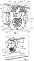
- the partial hollow cylinder 56 is designed to be open at its two hollow cylinder longitudinal ends, so that the two partial cylinder end surfaces 54 of the partial cylinder bodies 541, 542 inserted into the partial hollow cylinder 56 are laterally uncovered, as for example in the Figures 4, 5 and 6 can be seen.
- a partial cylinder or partial hollow cylinder is always to be understood as a cylinder with a sector angle of a maximum of 180 °.
- the sector angle of the partially hollow cylinder is approximately 160 °, so that the traction accumulator 30 at an insertion angle of a maximum of 20 ° in relation to the longitudinal axis of the traction accumulator 30 in its in the Figure 1 locking position shown can be threaded.
- the sector angle of the two part-cylinder bodies 541, 542, on the other hand, is approximately 180 °.
- the two partial cylinder bodies 541, 542 are arranged on the side of the traction accumulator 30 or of the frame section 22 facing the removal direction E.
- the two partial cylinder bodies 541, 542 are arranged without a gap and directly adjacent to the side edge of the pivoting end face of the traction accumulator 30 facing the removal direction E.
- the aforementioned side edge forms the transition between the relevant end face 91 and the distal side wall 33 of the traction accumulator 30 facing the removal direction.
- the two partial cylinder bodies 541, 542 merge steplessly into the distal side wall 33.
- the pivot joint holder assembly 40 has an electrical connector assembly which is formed by a traction battery-side contact connector 52 with several electrical contact elements 53 and a corresponding and complementary to this, frame-fixed mating contact connector 50 with several corresponding electrical mating contact elements 51.
- the contact plane of the contact elements 53 and the mating contact elements 51 lies approximately in a longitudinal plane in relation to the cylinder axis 58, this longitudinal plane being approximately perpendicular to the traction accumulator longitudinal axis.
- the radial distance R between the cylinder axis 58 and the closest contact element 53 or the closest mating contact element 51 should be as large as possible, and in the present case is approximately 40 mm.
- An electrical display 99 is arranged between the contact plug 52 and the partial cylinder body 541, 542, which displays the charge status of the traction accumulator 30.
- the pivot joint holding arrangement 40 also has a lateral guide which is formed by two guide tongues 801, 802 arranged laterally on the frame joint module 42 and two corresponding guide grooves 821, 822 on the battery joint module 44, the base planes of which lie in a transverse plane to the cylinder axis 58.
- the connector arrangement and the electrical display 99 are arranged between the two guide tongues 801, 802 or the two guide grooves 821, 822.
- the frame-side frame hinge module 42 is attached to the electric bicycle frame section by a fixing arrangement 96, as shown in FIG Figure 3 is shown.
- the fixing arrangement 92 consists of two screw connections with which the frame joint module 42 is fixed to the relevant wall section of the relevant frame section 22.
- the distance between the cylinder axis 58 and the fixing plane of the fixing arrangement 96 in a direction transverse to the longitudinal axis of the traction accumulator 30 is approximately half the cylinder diameter 10 mm / 2 plus approximately 2 mm, i.e. approximately a total of 7 mm in the present case. This realizes a relatively small lever arm with regard to longitudinal forces which are transmitted to the frame section 22 by the swivel joint holding arrangement 40.
- the locking holder arrangement 60 has on the frame holding module 64 an unlocking lock 66, by actuating it with a suitable unlocking key a movable locking bolt 68 from a locking position into an unlocking position can be moved. In the locking position, the locking bar 68 engages behind a rigid battery-side locking body 70 which is part of the battery holding module 62.
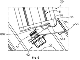
- the embodiment shown differs only in the electric bicycle frame section 220 from that of the embodiment of FIG Figures 1-5 .
- the electric bicycle frame portion 220 of the Figure 6 illustrated embodiment is open at the top, so that the removal of the traction accumulator 30 from the frame section 220 takes place from the bottom to the top or the insertion takes place from the top to the bottom.
- the removal direction E is therefore oriented upwards, whereas the locking direction V is oriented downwards.
Landscapes
- Engineering & Computer Science (AREA)
- Chemical & Material Sciences (AREA)
- Mechanical Engineering (AREA)
- Chemical Kinetics & Catalysis (AREA)
- Electrochemistry (AREA)
- General Chemical & Material Sciences (AREA)
- Combustion & Propulsion (AREA)
- Transportation (AREA)
- Aviation & Aerospace Engineering (AREA)
- Battery Mounting, Suspending (AREA)
- Arrangement Or Mounting Of Propulsion Units For Vehicles (AREA)
Abstract
Description
- Die Erfindung bezieht sich auf ein Elektrofahrrad-Akkuhalterungsensemble zum werkzeugfreien Einsetzen eines Traktionsakkumulators an oder in einen Elektrofahrrad-Rahmenabschnitt mit einer Schwenkbewegung in Verriegelungsrichtung bzw. zum werkzeugfreien Entnehmen des Traktionsakkumulators von oder aus dem Elektrofahrrad-Rahmenabschnitt mit einer Schwenkbewegung in Entnahmerichtung.
- Unter einem Elektrofahrrad sind vorliegend alle Mehrräder, insbesondere Zweiräder oder Dreiräder, zu verstehen, die einen elektrischen Traktionsakkumulator aufweisen, der bedarfsweise von einem Rahmenabschnitt des Elektrofahrrads abgenommen werden kann, beispielsweise, um den Traktionsakkumulator räumlich getrennt von dem Elektrofahrrad aufladen und/oder diebstahlsicher unterbringen zu können.
- Hierzu weist das Elektrofahrrad ein Akkuhalterungsensemble auf, das es erlaubt, den Traktionsakkumulator mit wenigen Handgriffen und insbesondere werkzeugfrei von dem Elektrofahrrad-Rahmenabschnitt zu entfernen. Unter "werkzeugfrei" ist vorliegend zu verstehen, dass hierzu kein Werkzeug erforderlich ist, das beispielsweise mehrere Umdrehungen zum Lösen oder Fixieren einer Schraube u.ä. ausführen muss. Selbstverständlich kann zum Entnehmen bzw. zum Einsetzen des Traktionsakkumulators beispielsweise ein Schloss und ein Schlüssel vorgesehen sein, um beispielsweise einen Diebstahlschutz darzustellen.
- Aus
DE 10 2018 006689 A1 ,DE 10 2019 100 673 A1 undDE 10 2017 005 434 A1 sind jeweils Elektrofahrrad-Akkuhalterungsensembles zum werkzeugfreien Einsetzen bzw. Entnehmen eines Traktionsakkumulators bekannt, wobei der Traktionsakkumulator durch eine Schwenkbewegung in das Akkuhalterungsensemble eingesetzt bzw. aus diesem entnommen wird. Hierzu ist eine Schwenkgelenk-Halteanordnung an einem Längsende des Traktionsakkumulators vorgesehen, das im Folgenden das Schwenk-Längsende genannt wird. An dem anderen Längsende des Traktionsakkumulators ist eine Verriegelungs-Halteanordnung vorgesehen, die der Verriegelung bzw. Entriegelung des Traktionsakkumulators in dem Akkuhalterungsensemble dient. - Die Schwenkgelenk-Halteanordnung weist an dem traktionsakku-seitigen Akkugelenkmodul eine konkave Ausnehmung auf, in die eine korrespondierende konvexe Ausstülpung des rahmenfesten Rahmengelenkmoduls eingreift, sodass auf diese Weise beim Entnehmen bzw. Verriegeln der Traktionsakkumulator eine Schwenkbewegung um das auf diese Weise gebildete Schwenkgelenk ausführt.
- Die Entnahmerichtung, in der der Traktionsakkumulator von der Schwenkgelenk-Halteanordnung entnommen wird, kann beispielsweise nach oben gerichtet sein, sodass der Traktionsakkumulator beispielsweise aus einer entsprechenden Ausnehmung des Elektrofahrrad-Rahmenabschnitts nach oben entnommen werden kann. Beim Einsetzen des Traktionsakkumulators in die Schwenkgelenk-Halteanordnung von oben ist eine relativ einfache Kontrollierbarkeit des Einsetzvorgangs gegeben. Allerdings wird bei immer mehr Elektrofahrrädern eine Entnahme nach unten bzw. ein Einsetzen des Traktionsakkumulators von unten in die Schwenkgelenk-Halteanordnung realisiert, um mehr Freiheiten bei der Rahmenkonstruktion und/oder um ein eleganteres Erscheinungsbild des betreffenden Elektrofahrrad-Rahmenabschnitts bieten zu können. Hierbei ist die visuelle Kontrolle beim Einsetzen bzw. Einfädeln des Akkugelenksmoduls in das rahmenfeste Rahmengelenkmodul erheblich erschwert.
- Die
DE 2019 100 673 A1 offenbart an dem Rahmengelenkmodul eine konvexe Ausstülpung, in die eine konkave Ausnehmung des Akkugelenkmoduls eingefädelt werden muss. Da der Traktionsakkumulator beim Einsetzen nur von der Seite aus sichtbar ist, muss das Einsetzen der Ausnehmung in die Ausstülpung praktisch blind erfolgen. - Aufgabe der Erfindung vor diesem Hintergrund ist es, ein Elektrofahrrad-Akkuhalterungsensemble zu schaffen, das eine verbesserte visuelle Kontrolle des Einsetzens des Traktionsakkumulators in die Schwenkgelenk-Halteanordnung erlaubt.
- Diese Aufgabe wird erfindungsgemäß gelöst mit einem Elektrofahrrad-Akkuhalterungsensemble mit den Merkmalen des Anspruchs 1.
- Das erfindungsgemäße Elektrofahrrad-Akkuhalterungsensemble zum werkzeugfreien Einsetzen des Traktionsakkumulators an bzw. in einen Elektrofahrrad-Rahmenabschnitt mit einer Schwenkbewegung weist einen entsprechenden Elektrofahrrad-Rahmenabschnitt, einen Traktionsakkumulator sowie eine Schwenkgelenk-Halteanordnung an einem Längsende des Traktionsakkumulators und eine Verriegelungs-Halteanordnung an dem anderen Längsende des Traktionsakkumulators auf. In dem am Elektrofahrrad-Rahmenabschnitt verriegelten Zustand kann der Traktionsakkumulator außen auf den betreffenden Rahmenabschnitt aufgesetzt sein, kann jedoch auch quasi unsichtbar in einer entsprechenden Ausnehmung innerhalb des betreffenden Rahmenabschnitts vollständig versenkt sein. Das Einsetzen des Traktionsakkumulators in die rahmenseitige Halteanordnung kann grundsätzlich von oben, von der Seite oder von unten erfolgen.
- Das Akkuhalterungsensemble weist eine Schwenkgelenk-Halteanordnung an dem Schwenk-Längsende des Traktionsakkumulators und eine Verriegelungs-Halteanordnung an dem Verriegelungs-Längsende des Traktionsakkumulators auf. Jede Halteanordnung besteht jeweils aus zwei Modulen, nämlich einem rahmenseitigen bzw. rahmenfesten Modul und einem akkuseitigen Modul. Die Schwenkgelenk-Halteanordnung wird von einem rahmenfesten Rahmengelenkmodul und von einem traktionsakku-seitigen Akkugelenkmodul gebildet.
- Das Akkugelenkmodul weist einen konvexen Teilzylinderkörper und das Rahmengelenkmodul weist einen korrespondierenden konkaven Teilhohlzylinder auf, in den der Teilzylinderkörper annähernd spielfrei eingreift. Die Zylinderachse des Teilzylinderkörpers bzw. des Teilhohlzylinders bildet die Schwenkachse der Schwenkgelenk-Halteanordnung. Der Teilzylinderkörper und der Teilhohlzylinder sind an der der Entnahmerichtung zugewandten Seite des Traktionsakkumulators bzw. des Rahmenabschnitts angeordnet. Unter einem Teilzylinderkörper bzw. einem Teilhohlzylinder ist vorliegend eine räumliche Form zu verstehen, die im Wesentlichen jedoch nicht notwendigerweise vollständig zylindrisch ausgebildet ist. In jedem Fall sind der Teilzylinderkörper und der korrespondierende Teilhohlzylinder so ausgebildet, dass jedenfalls die finale Schwenkbewegung des Traktionsakkumulators um eine praktisch starre Schwenkachse erfolgt, die Schwenkachse sich also während der finalen Schwenkbewegung nicht wesentlich verändert. Hierzu ist insbesondere der Teilzylinderkörper über seine Funktionsfläche im Wesentlichen zylindrisch ausgebildet, wohingegen der Teilhohlzylinder ebenfalls zylindrisch ausgebildet ist. Alternativ kann der Teilhohlzylinder aber auch von mehreren kleinen ebenen Flächen gebildet sein, die die Wirkung eines Teilhohlzylinders haben, allerdings dabei den Nachteil höherer Flächenpressungen in Kauf nehmen.
- Durch die Anordnung des konvexen Teilzylinderkörpers an der betreffenden Stirnseite des Traktionsakkumulators ist die visuelle Kontrolle beim Einfädeln des akkuseitigen Teilzylinderkörpers in den rahmenseitigen konkaven Teilhohlzylinder erheblich verbessert. Der konvexe Teilzylinderkörper, der aus der Grundebene der betreffenden Stirnseite des Traktionsakkumulators axial hervorragt, ist auch von der Seite aus sichtbar, sodass das Einfädeln auch von der Seite aus visuell einfach kontrolliert werden kann. Dies ist insbesondere bei einer Einsetz- und Verriegelungsbewegung bzw. Verriegelungsrichtung von unten nach oben besonders hilfreich, bei der die Sichtbarkeit auf das rahmenseitige Rahmengelenkmodul schon durch die schlechten Lichtverhältnisse erheblich behindert und von oben aus sogar ausgeschlossen ist. Die Sichtbarkeit des konvexen Teilzylinderkörpers kann noch durch entsprechende Farbwahl einer hellen und kontrastierenden Farbe des Teilzylinderkörpers verbessert werden.
- Der Teilzylinderkörper und der Teilhohlzylinder sind an der der Akku-Entnahmerichtung zugewandten Seite des Traktionsakkumulators beziehungsweise des betreffenden Elektrofahrrad-Rahmenabschnitts angeordnet. Im Falle einer Unterbringung des Traktionsakkumulators innerhalb des Rahmenabschnitts sind der Teilzylinderkörper und der Teilhohlzylinder also möglichst nah an der betreffenden Öffnung des Rahmenabschnitts angeordnet. Auch durch diese Maßnahme wird die Sichtbarkeit des akkuseitigen Teilzylinderkörpers beim Einsetzen bzw. Einfädeln in den Teilhohlzylinder möglichst lange sichergestellt. Der Teilzylinderkörper ist nah, und besonders bevorzugt unmittelbar an dem der Entnahmerichtung zugewandten Seitenrand der Schwenk-Stirnseite des Traktionsakkumulators angeordnet. Unter einer nahen Anordnung ist eine Entfernung des Teilzylinderkörpers von dem Seitenrand von maximal wenigen Millimetern, insbesondere von höchstens 5 mm zu verstehen.
- Der Traktionsakkumulator weist eine der Entnahmerichtung zugewandte distale Seitenwand auf. Vorzugsweise geht der Teilzylinderkörper stufenlos bzw. sprungfrei in diese Seitenwand über. Die zylindrische Oberfläche des Teilzylinderkörpers mündet also tangentenstetig in die ebene distale Seitenwand des Traktionsakkumulators. Auf diese Weise ist der Teilzylinderkörper so nah wie technisch möglich an der betreffenden distalen Seitenwand angeordnet. Hierdurch sind für den Schwenkvorgang weder akkuseitig noch rahmenseitig besondere Freischnitte erforderlich. Ferner ist hierdurch die konstruktiv bestmögliche Sichtbarkeit des Teilzylinderkörpers realisiert.
- Gemäß einer bevorzugten Ausgestaltung der Erfindung ist der Teilhohlzylinder starr an dem Rahmengelenkmodul vorgesehen und ist hinterschneidungsfrei ausgebildet. Der Teilhohlzylinder beschreibt also einen Teilzylinder von maximal 180°, besonders bevorzugt von 175°-150°, was einem Schwenkwinkel von 5°-30° entspricht. Der Schwenkwinkel beschreibt den Winkel, unter dem das Einfädeln des Traktionsakkumulators bzw. des Teilzylinderkörpers initial in das Rahmengelenkmodul bzw. in den konkaven Teilhohlzylinder maximal erfolgen kann.
- Gemäß einer bevorzugten Ausgestaltung ist der Teilhohlzylinder an mindestens einem Hohlzylinder-Längsende offen ausgebildet, sodass eine Teilzylinderkörper-Endfläche des in den Teilhohlzylinder eingesetzten Teilzylinderkörpers seitlich unverdeckt ist, also seitlich sichtbar ist. Hierdurch wird die Sichtbarkeit insbesondere beim Einfädeln und die Kontrollierbarkeit des bereits in den Teilhohlzylinder eingefädelten Teilzylinderkörpers erheblich verbessert bzw. überhaupt erst ermöglicht.
- Vorzugsweise weist die Schwenkgelenk-Halteanordnung eine elektrische Steckeranordnung auf, die von einem traktionsakku-seitigen Kontaktstecker mit mehreren elektrischen Kontaktelementen und einem hierzu korrespondierenden und komplementären rahmenfesten Gegenkontaktstecker mit mehreren elektrischen Gegenkontaktelementen gebildet wird. Die Kontaktebene der Kontaktelemente und der Gegenkontaktelemente liegt ungefähr in einer radialen Längsebene in Bezug auf die Zylinderachse des Teilzylinderkörpers bzw. des Teilhohlzylinders. Hierdurch wird eine exakt tangentiale Kontaktierungs-Bewegung der Kontaktelemente und der Gegenkontaktelemente zueinander realisiert.
- Besonders bevorzugt ist vorgesehen, dass der radiale Abstand zwischen der Zylinderachse und dem nächstliegenden Kontaktelement bzw. Gegenkontaktelement mindestens 30 mm, insbesondere mindestens 35 mm beträgt. Besonders bevorzugt beträgt der radiale Abstand abzüglich des halben Zylinderdurchmessers des Teilzylinderkörpers mindestens 30 mm, und insbesondere mindestens 35 mm. Je größer der Abstand der Kontaktelemente bzw. der Gegenkontaktelemente zur Zylinderachse ist, desto weniger ist die Tangentiale der Steckbewegung geneigt zur Längsrichtung des Traktionsakkumulators zu Beginn der elektrischen Kontaktierung der Kontaktelemente mit den Gegenkontaktelementen.
- Auf diese Weise können die Kontaktelemente bzw. die Gegenkontaktelemente weitgehend geradlinig und axial zusammengesteckt werden, wodurch grundsätzlich eine bessere elektrische Kontaktierung sichergestellt werden kann. Ferner können die Kontaktelemente und die Gegenkontaktelemente exakt in Längsrichtung ausgerichtet werden, wodurch Bauraum eingespart wird.
- Ein großer radialer Abstand zwischen der Zylinderachse und dem nächstliegenden Kontaktelement bzw. Gegenkontaktelement wird konstruktiv durch die randseitige Anordnung des Teilzylinderkörpers unmittelbar an dem Seitenrand der Schwenk-Stirnseite des Traktionsakkumulators erst ermöglicht. Denn ein Teilhohlzylinder kann nicht unmittelbar randseitig angeordnet werden, weil der Teilhohlzylinder eine Seitenwand erfordert, die den Teilhohlzylinder bildet. Je schmaler diese Seitenwand wäre, desto eher stellt sie ein Verletzungsrisiko dar und desto leichter könnte sie abgebrochen oder verbogen werden.
- Vorzugsweise ist an der Gelenk-Stirnseite des Traktionsakkumulators radial zwischen dem Kontaktstecker und dem Teilzylinderkörper eine elektrische Anzeige angeordnet. Die elektrische Anzeige kann beispielsweise den elektrischen Ladezustand des Traktionsakkumulators anzeigen.
- Gemäß einer bevorzugten Ausgestaltung weist der Teilzylinderkörper eine Rippenstruktur auf. Die Rippen können insbesondere in einer Zylinder-Querebene stehen. Durch die Rippenstruktur wird ein aus Kunststoff spritzgegossener Teilzylinderkörper formtreu und präzise hergestellt, da insbesondere eine Materialausdehnung nach dem Spritzgießen hierfür in den Rippen-Zwischenräumen Platz findet. Auf diese Weise kann ein annähernd spielfreies und gleichzeitig klemmfreies Ineinandergreifen des Teilzylinderkörpers und des Teilhohlzylinders sichergestellt werden.
- Vorzugsweise weist die Schwenkgelenk-Halteanordnung eine Lateralführung auf, die von einer Führungszunge und einer korrespondierenden Führungsnut gebildet ist, deren Grundebenen in einer Querebene zur Zylinderachse liegen. Die Führungszunge kann beispielsweise an dem Rahmengelenkmodul und die korrespondierende Führungsnut an dem Akkugelenkmodul vorgesehen sein. Es können auch zwei Lateralführungen vorgesehen sein.
- Durch die auf diese Weise gebildete laterale Führung wird der Traktionsakkumulator über den Schwenkbereich und in der Verriegelungsposition lateral geführt. Dies ist insbesondere dann von großer Wichtigkeit, wenn der Teilhohlzylinder seitlich offen ausgebildet ist, also selbst keine laterale Führungsaufgabe übernimmt.
- Gemäß einer bevorzugten Ausgestaltung der Erfindung ist das Rahmengelenkmodul an dem Elektrofahrrad-Rahmenabschnitt durch eine Fixieranordnung dauerhaft fixiert. Die Zylinderachse und die Fixierebene der Fixieranordnung sind, in einer Richtung quer zur Längsachse des Traktionsakkumulators, vorzugsweise weniger als 15 mm, besonders bevorzugt weniger als 10 mm voneinander beabstandet. Die Zylinderachse und die Fixierebene der Fixieranordnung sind nur gering oder gar nicht zueinander versetzt angeordnet. Wenn der Traktionsakkumulator in der Akkuhalterung verriegelt ist, werden relativ hohe Klemmkräfte in Längsrichtung des Traktionsakkumulators erzeugt. Da der Abstand zwischen der Fixierebene der Fixieranordnung und der Zylinderachse klein ist, ist auch der hiermit identische Hebelarm für die Krafteinleitung der in Längsrichtung wirkenden Einspannkraft kurz bzw. gleich Null, sodass die strukturelle Stabilität des Akkuhalterungsensembles hoch ist.
- Im Folgenden werden zwei Ausführungsbeispiele der Erfindung anhand der Zeichnungen näher erläutert. Es zeigen:
-
Figur 1 schematisch einen Elektrofahrrad-Rahmenabschnitt mit einem Akkuhalterungsensemble, das im Wesentlichen aus einer Verriegelungs-Halteanordnung an einem Längsende und einer Schwenkgelenk-Halteanordnung an dem anderen Längsende des Traktionsakkumulators besteht, wobei der Traktionsakkumulator nach unten von dem Elektrofahrrad-Rahmenabschnitt entnommen bzw. in den Rahmenabschnitt eingesetzt wird, -
Figur 2 eine perspektivische Ansicht eines Akkugelenkmoduls der Schwenkgelenk-Halteanordnung derFigur 1 , -
Figur 3 eine perspektivische Ansicht eines Rahmengelenkmoduls der Schwenkgelenk-Halteanordnung derFigur 1 , -
Figur 4 einen Längsschnitt der Schwenkgelenk-Halteanordnung derFigur 1 , -
Figur 5 eine perspektivische Ansicht der Schwenkgelenk-Halteanordnung derFigur 4 , und -
Figur 6 einen Längsschnitt einer Schwenkgelenk-Halteanordnung einer zweiten Ausführungsform, bei der der Traktionsakkumulator nach oben aus dem Elektrofahrrad-Rahmenabschnitt entnommen bzw. in den Rahmenabschnitt eingesetzt wird. - In der
Figur 1 ist schematisch ein Elektrofahrrad 10 dargestellt, das beispielsweise als sogenanntes Pedelec ausgebildet sein kann. Das Elektrofahrrad 10 weist einen Fahrradrahmen auf, von dem vorliegend nur ein Rahmenabschnitt 22 gezeigt ist, beispielsweise ein Rahmenabschnitt 22, der eine steife Traverse oder einen Teil davon zwischen dem Lenkerrohr und dem Sattelrohr des Fahrradrahmens bildet. Der Rahmenabschnitt 22 kann beispielsweise als im Querschnitt rechteckiges Hohlprofil ausgebildet sein, das eine nach unten orientierte Akku-Einstecköffnung 34 aufweist, durch die hindurch der Traktionsakkumulator 30 aus dem Rahmenabschnitt 22 entnommen bzw. in den Rahmenabschnitt 22 eingesetzt werden kann. In den beiden vorliegenden Ausführungsbeispielen ist der Rahmenabschnitt 22,220 jeweils gleichseitig sechsseitig ausgebildet, wie in derFigur 2 erkennbar ist. - Das Elektrofahrrad 10 weist ein angetriebenes Antriebsrad 12 auf, beispielsweise das Hinterrad des Fahrrads 10. Das Antriebsrad 12 wird über eine Antriebskette 14 von einer Tretkurbel 16 angetrieben. Die Tretkurbel 16 wird ferner bedarfsweise zusätzlich durch einen elektrischen Traktionsmotor 18 angetrieben, der durch eine Antriebssteuerung 20 mit elektrischer Energie versorgt wird. Die Antriebssteuerung 20 erhält die elektrische Traktions-Energie von einem Traktionsakkumulator 30, der in seiner verriegelten Gebrauchsposition in einer nach unten öffnenden Akkuaufnahme-Ausnehmung 31 in dem Rahmenabschnitt 22 untergebracht ist.
- Der Traktionsakkumulator 30 wird von einer Schwenkgelenk-Halteanordnung 40 an der einen Stirnseite 91 bzw. dem einen Längsende LV des Traktionsakkumulators 30 und von einer Verriegelungs-Halteanordnung 60 an der anderen Stirnseite 92 bzw. dem anderen Längsende LG des Traktionsakkumulators 30 werkzeuglos entnehmbar gehalten. Die beiden Stirnseiten 91,92 des Traktionsakkumulators 30 bilden die jeweiligen Längsenden LV,LG des Traktionsakkumulators 30.
- Die Längsachse Y des Traktionsakkumulators 30 ist die Längsachse zwischen den beiden Längsenden LV,LG bzw. zwischen den beiden Stirnseiten des Traktionsakkumulators 30. Die Entnahmeachse X entspricht der initialen Bewegungsrichtung des Traktionsakkumulators 30 beim Entnehmen aus der Akku-Ausnehmung 31 in einer Entnahmerichtung E bzw. der finalen Bewegungsrichtung beim Einsetzen des Traktionsakkumulators 30 in die Akku-Ausnehmung 31 in Verriegelungsrichtung V. Die Querachse Z ist die dritte Raumachse, die senkrecht zur Längsachse Y und senkrecht zur Entnahmeachse X orientiert ist.
- Die Verriegelungs-Halteanordnung 60 an dem der Schwenkgelenk-Halteanordnung 40 gegenüberliegenden Längsende des Traktionsakkumulators 30 weist ein rahmenseitiges Rahmenhaltemodul 64 und ein traktionsakku-seitiges Akkuhaltemodul 62 auf, das mit dem Rahmenhaltemodul 64 in der
Figur 1 in der Verriegelungsposition dargestellt ist. Die Schwenkgelenk-Halteranordnung 40 wird von einem rahmenfesten Rahmengelenkmodul 42 und von einem traktionsakku-seitigen Akkugelenkmodul 44 gebildet. - Der Traktionsakkumulator 30 besteht aus einem langgestreckten Batteriemodul 32 mit einem gleichseitig sechseckigen Querschnitt, wobei an dem Schwenk-Längsende LG des Batteriemoduls 32 das Akkugelenkmodul 44 und an dem Verriegelungs-Längsende LV das Akkuhaltemodul 62 dauerhaft befestigt ist.
- Das Schwenkgelenk wird von zwei exakt axial zueinander ausgerichteten Teilzylinderkörpern 541,542 an dem Akkugelenkmodul 44 und einem hierzu korrespondierenden konkaven Teilhohlzylinder 56 an dem Rahmengelenkmodul 42 gebildet. Die gemeinsame Zylinderachse 58 der beiden Teilzylinderkörper 541,542 bzw. des Teilhohlzylinders 56 bildet die Schwenkachse der auf diese Weise gebildeten Schwenkgelenk-Halteranordnung 40. Der Zylinderdurchmesser D der beiden Teilzylinderkörper 541,542 beträgt ungefähr 10 mm. Die beiden Teilzylinderkörper 541,542 weisen jeweils eine Rippenstruktur auf, wobei die Rippen in einer Querebene zur Zylinderachse 58 angeordnet sind.
- Der Teilhohlzylinder 56 ist an seinen beiden Hohlzylinder-Längsenden offen ausgebildet, so dass die beiden Teilzylinder-Endflächen 54 der in den Teilhohlzylinder 56 eingesetzten Teilzylinderkörper 541,542 seitlich unverdeckt sind, wie beispielsweise in den
Figuren 4, 5 sowie 6 zu erkennen ist. - Unter einem Teilzylinder bzw. Teilhohlzylinder ist vorliegend stets ein Zylinder mit einem Sektorwinkel von maximal 180 ° zu verstehen. Im vorliegenden Fall beträgt der Sektorwinkel des Teilhohlzylinders ca. 160°, sodass der Traktionsakkumulator 30 in einem Einsetzwinkel von maximal 20° im Verhältnis zur Längsachse des Traktionsakkumulators 30 in seiner in der
Figur 1 dargestellten Verriegelungsposition eingefädelt werden kann. Der Sektorwinkel der beiden Teilzylinderkörper 541,542 beträgt dagegen annähernd 180°. - Wie in der
Figur 2 erkennbar ist, sind die beiden Teilzylinderkörper 541,542 an der der Entnahmerichtung E zugewandten Seite des Traktionsakkumulators 30 bzw. des Rahmenabschnitts 22 angeordnet. Insbesondere sind die beiden Teilzylinderkörper 541,542 abstandslos und unmittelbar angrenzend an dem der Entnahmerichtung E zugewandten Seitenrand der Schwenk-Stirnseite des Traktionsakkumulators 30 angeordnet. Der vorgenannte Seitenrand bildet den Übergang zwischen der betreffenden Stirnseite 91 und der der Entnahmerichtung zugewandten distalen Seitenwand 33 des Traktionsakkumulators 30. Die beiden Teilzylinderkörper 541,542 gehen stufenlos in die distale Seitenwand 33 über. - An dem Schwenk-Längsende LG weist die Schwenkgelenk-Halteranordnung 40 eine elektrische Steckeranordnung auf, die von einem traktionsakku-seitigen Kontaktstecker 52 mit mehreren elektrischen Kontaktelementen 53 und einem hierzu korrespondierenden und hierzu komplementären rahmenfesten Gegenkontaktstecker 50 mit mehreren korrespondierenden elektrischen Gegenkontaktelementen 51 gebildet wird. Die Kontaktebene der Kontaktelemente 53 und der Gegenkontaktelemente 51 liegt ungefähr in einer Längsebene in Bezug auf die Zylinderachse 58, wobei diese Längsebene ungefähr senkrecht zur Traktionsakkumulator-Längsachse steht. Der radiale Abstand R zwischen der Zylinderachse 58 und dem nächstliegenden Kontaktelement 53 bzw. dem nächstliegenden Gegenkontaktelement 51 sollte möglichst groß sein, und beträgt vorliegend ca. 40 mm.
- Zwischen dem Kontaktstecker 52 und dem Teilzylinderkörper 541,542 ist eine elektrische Anzeige 99 angeordnet, die den Ladezustand des Traktionsakkumulators 30 anzeigt.
- Die Schwenkgelenk-Halteanordnung 40 weist ferner eine Lateralführung auf, die von zwei seitlich an dem rahmenseitigen Rahmengelenkmodul 42 angeordneten Führungszungen 801,802 und zwei hierzu korrespondierenden Führungsnuten 821,822 an dem Akkugelenkmodul 44 gebildet wird, deren Grundebenen in einer Querebene zur Zylinderachse 58 liegen. Die Steckeranordnung und die elektrische Anzeige 99 sind zwischen den beiden Führungszungen 801,802 bzw. den beiden Führungsnuten 821,822 angeordnet.
- Das rahmenseitige Rahmengelenkmodul 42 ist durch eine Fixieranordnung 96 an dem Elektrofahrrad-Rahmenabschnitt befestigt, wie in
Figur 3 dargestellt ist. Im vorliegenden Ausführungsbeispiel besteht die Fixieranordnung 92 aus zwei Schraubverbindungen, mit denen das Rahmengelenkmodul 42 an dem betreffenden Wandabschnitt des betreffenden Rahmenabschnitts 22 fixiert ist. Wie in denFiguren 3 und4 erkennbar ist, beträgt der Abstand der Zylinderachse 58 und der Fixierebene der Fixieranordnung 96 in einer Richtung quer zur Längsachse des Traktionsakkumulators 30 vorliegend ungefähr den halben Zylinderdurchmesser 10mm/2 zzgl. ca 2 mm, also vorliegend ungefähr insgesamt 7 mm. Hierdurch wird ein relativ kleiner Hebelarm in Bezug auf Längskräfte realisiert, die durch die Schwenkgelenk-Halteanordnung 40 auf den Rahmenabschnitt 22 übertragen werden. - Die Verriegelungs-Halteranordnung 60 weist an dem Rahmenhaltemodul 64 ein Entriegelungs-Schloss 66 auf, durch dessen Betätigung mit einem passenden Entriegelungs-Schlüssel ein beweglicher Verriegelungs-Riegel 68 aus einer Verriegelungsposition in eine Entriegelungsposition verschoben werden kann. Der Verriegelungsriegel 68 hintergreift in der Verriegelungsposition einen starren akkuseitigen Riegelkörper 70, der Teil des Akkuhaltemoduls 62 ist.
- Das in der
Figur 6 dargestellte Ausführungsbeispiel unterscheidet sich lediglich in dem Elektrofahrrad-Rahmenabschnitt 220 von dem des Ausführungsbeispiels derFiguren 1-5 . Der Elektrofahrrad-Rahmenabschnitt 220 des in derFigur 6 dargestellten Ausführungsbeispiels ist nach oben geöffnet, sodass die Entnahme des Traktionsakkumulators 30 aus dem Rahmenabschnitt 220 von unten nach oben bzw. das Einsetzen von oben nach unten erfolgt. Die Entnahmerichtung E ist also nach oben orientiert, wohingegen die Verriegelungsrichtung V nach unten gerichtet ist.
Claims (11)
- Elektrofahrrad-Akkuhalterungsensemble zum werkzeugfreien Einsetzen eines Traktionsakkumulators (30) an einen Elektrofahrrad-Rahmenabschnitt (22) mit einer Schwenkbewegung in Verriegelungsrichtung (V) bzw. zum werkzeugfreien Entnehmen des Traktionsakkumulators (30) von dem Elektrofahrrad-Rahmenabschnitt (22) mit einer Schwenkbewegung in Entnahmerichtung (E), wobei der Traktionsakkumulator (30) an seinen beiden Längsenden (LG,LV) zwei voneinander abgewandte Stirnseiten (91,92) aufweist, mit
einer Schwenkgelenk-Halteanordnung (40) an dem Schwenk-Längsende (LG) des Traktionsakkumulators (30) und einer Verriegelungs-Halteanordnung (60) an dem Verriegelungs-Längsende (LV) des Traktionsakkumulators (30),
wobei die Schwenkgelenk-Halteanordnung (40) von einem rahmenfesten Rahmengelenkmodul (42) und von einem traktionsakku-seitigen Akkugelenkmodul (44) gebildet wird,
wobei das Akkugelenkmodul (44) einen konvexen Teilzylinderkörper (541,542) und das Rahmengelenkmodul (42) einen korrespondierenden konkaven Teilhohlzylinder (56) aufweist, in den der Teilzylinderkörper (541,542) annähernd spielfrei eingreift, wobei die Zylinderachse (58) des Teilzylinderkörpers (541,542) bzw. des Teilhohlzylinders (56) die Schwenkachse der Schwenkgelenk-Halteanordnung (40) bildet, und
wobei der Teilzylinderkörper (541,542) und der Teilhohlzylinder (56) an der der Entnahmerichtung (E) zugewandten Seite des Traktionsakkumulators (30) bzw. des Rahmenabschnitts (22) angeordnet ist. - Elektrofahrrad-Akkuhalterungsensemble nach Anspruch 1, wobei der Teilzylinderkörper (541,542) an dem der Entnahmerichtung (E) zugewandten Seitenrand der Schwenk-Stirnseite (91) des Traktionsakkumulators (30) angeordnet ist.
- Elektrofahrrad-Akkuhalterungsensemble nach einem der vorangegangenen Ansprüche, wobei der Traktionsakkumulator (30) eine der Entnahmerichtung (E) zugewandte distale Seitenwand (33) aufweist, und der Teilzylinderkörper (541,542) stufenlos in die distale Seitenwand (33) übergeht.
- Elektrofahrrad-Akkuhalterungsensemble nach einem der vorangegangenen Ansprüche, wobei der Teilhohlzylinder (56) hinterschneidungsfrei ausgebildet ist.
- Elektrofahrrad-Akkuhalterungsensemble nach einem der vorangegangenen Ansprüche, wobei die Schwenkgelenk-Halteanordnung (40) eine elektrische Steckeranordnung aufweist, die von einem traktionsakku-seitigen Kontaktstecker (52) mit mehreren elektrischen Kontaktelementen (53) und einem hierzu korrespondierenden und komplementären rahmenfesten Gegenkontaktstecker (50) mit mehreren elektrischen Gegenkontaktelementen (51) gebildet wird, wobei die Kontaktebene der Kontaktelemente (53) und der Gegenkontaktelemente (51) ungefähr in einer radialen Längsebene in Bezug auf die Zylinderachse (58) liegt.
- Elektrofahrrad-Akkuhalterungsensemble nach Anspruch 5, wobei der radiale Abstand (R) zwischen der Zylinderachse (58) und dem nächstliegenden Kontaktelement (53) bzw. Gegenkontaktelement (51) mindestens 30 mm, insbesondere mindestens 35 mm beträgt, und besonders bevorzugt der Abstand (R) abzüglich des halben Zylinderdurchmessers (D) des Teilzylinderkörpers (541,542) mindestens 30 mm, und insbesondere mindestens 35 mm beträgt.
- Elektrofahrrad-Akkuhalterungsensemble nach Anspruch 5 oder 6, wobei an der Gelenk-Stirnseite (41) des Traktionsakkumulators (30) radial zwischen dem Kontaktstecker (52) und dem Teilzylinderkörper (541,542) eine elektrische Anzeige (99) angeordnet ist.
- Elektrofahrrad-Akkuhalterungsensemble nach einem der vorangegangenen Ansprüche, wobei der Teilzylinderkörper (541,542) eine Rippenstruktur aufweist.
- Elektrofahrrad-Akkuhalterungsensemble nach einem der vorangegangenen Ansprüche, wobei der Teilhohlzylinder (56) an den Hohlzylinder-Enden offen ausgebildet ist, sodass eine Teilzylinderkörper-Endfläche (94) des in den Teilhohlzylinder (56) eingesetzten Teilzylinderkörpers (541,542) seitlich unverdeckt ist.
- Elektrofahrrad-Akkuhalterungsensemble nach einem der vorangegangenen Ansprüche, wobei die Schwenkgelenk-Halteanordnung (40) eine Lateralführung aufweist, die von einer Führungszunge (801,802) und einer korrespondierenden Führungsnut (821,822) gebildet wird, deren Grundebenen in einer Querebene zur Zylinderachse (58) liegen.
- Elektrofahrrad-Akkuhalterungsensemble nach einem der vorangegangenen Ansprüche, wobei das Rahmengelenkmodul (42) an dem Elektrofahrrad-Rahmenabschnitt (22) durch eine Fixieranordnung (96) fixiert ist und wobei die Zylinderachse (58) und die Fixierebene der Fixieranordnung (96) in einer Richtung quer zur Längsachse des Traktionsakkumulators (30) weniger als 15 mm, besonders bevorzugt weniger als 10 mm voneinander beabstandet sind.
Priority Applications (2)
| Application Number | Priority Date | Filing Date | Title |
|---|---|---|---|
| EP20162586.0A EP3878724B1 (de) | 2020-03-12 | 2020-03-12 | Elektrofahrrad-akkuhalterungsensemble |
| PCT/EP2021/056236 WO2021180871A1 (de) | 2020-03-12 | 2021-03-11 | Elektrofahrrad-akkuhalterungsensemble |
Applications Claiming Priority (1)
| Application Number | Priority Date | Filing Date | Title |
|---|---|---|---|
| EP20162586.0A EP3878724B1 (de) | 2020-03-12 | 2020-03-12 | Elektrofahrrad-akkuhalterungsensemble |
Publications (2)
| Publication Number | Publication Date |
|---|---|
| EP3878724A1 true EP3878724A1 (de) | 2021-09-15 |
| EP3878724B1 EP3878724B1 (de) | 2023-08-16 |
Family
ID=69804768
Family Applications (1)
| Application Number | Title | Priority Date | Filing Date |
|---|---|---|---|
| EP20162586.0A Active EP3878724B1 (de) | 2020-03-12 | 2020-03-12 | Elektrofahrrad-akkuhalterungsensemble |
Country Status (2)
| Country | Link |
|---|---|
| EP (1) | EP3878724B1 (de) |
| WO (1) | WO2021180871A1 (de) |
Cited By (2)
| Publication number | Priority date | Publication date | Assignee | Title |
|---|---|---|---|---|
| EP4300684A1 (de) * | 2022-06-28 | 2024-01-03 | Robert Bosch GmbH | Verbindungsvorrichtung zur verbindung eines akkupack mit einem verbraucher, akkupack und/oder verbraucher mit einer verbindungsvorrichtung |
| EP4410653A1 (de) * | 2023-02-02 | 2024-08-07 | G. Cartier Technologies | Abnehmbare stromversorgungseinheit und fahrzeug mit geschützten verbindungsanschlüssen |
Citations (7)
| Publication number | Priority date | Publication date | Assignee | Title |
|---|---|---|---|---|
| US20120145852A1 (en) * | 2010-11-12 | 2012-06-14 | Joy Industrial Co., Ltd. | Positioning device for battery box |
| CN202464077U (zh) * | 2012-03-08 | 2012-10-03 | 中华汽车工业股份有限公司 | 电动自行车电池盒安装装置 |
| CN203832691U (zh) * | 2014-03-10 | 2014-09-17 | 久鼎金属实业股份有限公司 | 电动自行车的电池安装结构 |
| DE102015010603A1 (de) * | 2015-08-18 | 2017-02-23 | Bmz Batterien-Montage-Zentrum Gmbh | Vorrichtung zum Energiespeichern und/oder Energieabgeben und Verfahren zur Verwendung einer Vorrichtung zum Energiespeichern und/oder Energieabgeben |
| DE102017005434A1 (de) | 2016-06-30 | 2018-01-04 | Shimano Inc. | Batteriehalter, Batterieeinheit und Batteriekomponente einschließend einen Batteriehalter und eine Batterieeinheit |
| DE102018006689A1 (de) | 2017-08-29 | 2019-02-28 | Marquardt Verwaltungs-Gmbh | Fahrzeug |
| DE102019100673A1 (de) | 2018-01-19 | 2019-07-25 | Shimano Inc. | Batteriehalter |
-
2020
- 2020-03-12 EP EP20162586.0A patent/EP3878724B1/de active Active
-
2021
- 2021-03-11 WO PCT/EP2021/056236 patent/WO2021180871A1/de not_active Ceased
Patent Citations (7)
| Publication number | Priority date | Publication date | Assignee | Title |
|---|---|---|---|---|
| US20120145852A1 (en) * | 2010-11-12 | 2012-06-14 | Joy Industrial Co., Ltd. | Positioning device for battery box |
| CN202464077U (zh) * | 2012-03-08 | 2012-10-03 | 中华汽车工业股份有限公司 | 电动自行车电池盒安装装置 |
| CN203832691U (zh) * | 2014-03-10 | 2014-09-17 | 久鼎金属实业股份有限公司 | 电动自行车的电池安装结构 |
| DE102015010603A1 (de) * | 2015-08-18 | 2017-02-23 | Bmz Batterien-Montage-Zentrum Gmbh | Vorrichtung zum Energiespeichern und/oder Energieabgeben und Verfahren zur Verwendung einer Vorrichtung zum Energiespeichern und/oder Energieabgeben |
| DE102017005434A1 (de) | 2016-06-30 | 2018-01-04 | Shimano Inc. | Batteriehalter, Batterieeinheit und Batteriekomponente einschließend einen Batteriehalter und eine Batterieeinheit |
| DE102018006689A1 (de) | 2017-08-29 | 2019-02-28 | Marquardt Verwaltungs-Gmbh | Fahrzeug |
| DE102019100673A1 (de) | 2018-01-19 | 2019-07-25 | Shimano Inc. | Batteriehalter |
Cited By (3)
| Publication number | Priority date | Publication date | Assignee | Title |
|---|---|---|---|---|
| EP4300684A1 (de) * | 2022-06-28 | 2024-01-03 | Robert Bosch GmbH | Verbindungsvorrichtung zur verbindung eines akkupack mit einem verbraucher, akkupack und/oder verbraucher mit einer verbindungsvorrichtung |
| EP4410653A1 (de) * | 2023-02-02 | 2024-08-07 | G. Cartier Technologies | Abnehmbare stromversorgungseinheit und fahrzeug mit geschützten verbindungsanschlüssen |
| FR3145513A1 (fr) * | 2023-02-02 | 2024-08-09 | G. Cartier Technologies | Unite d’alimentation electrique amovible et vehicule a connectique protegee |
Also Published As
| Publication number | Publication date |
|---|---|
| EP3878724B1 (de) | 2023-08-16 |
| WO2021180871A1 (de) | 2021-09-16 |
Similar Documents
| Publication | Publication Date | Title |
|---|---|---|
| DE202010018016U1 (de) | Blasformanordnung | |
| DE102004057164A1 (de) | Spritzgießmaschine | |
| DE102013008302A1 (de) | Werkzeug zum Spritzgießen von Kunststoffteilen | |
| WO2021023625A1 (de) | Haltevorrichtung für ein gegenelement | |
| DE4228383A1 (de) | Kugelgelenkeinheit, Kugelkopf und Kugelpfannenkörper für diese Kugelgelenkeinheit, Zylinderkolbengerät mit daran angebauter Kugelgelenkeinheit, Zylinderkolbengerät mit daran angebautem Kugelpfannenkörper, Verfahren zum Anschließen einer Kugelgelenkeinheit, Verfahren zum Anbringen eines Zylinderkolbengeräts an einer übergeordneten Konstruktion unter Verwendung einer Kugelgelenkeinheit | |
| EP3878724B1 (de) | Elektrofahrrad-akkuhalterungsensemble | |
| EP4136374A2 (de) | Endbefestigung einer flexiblen umhüllung für reinraumanwendungen | |
| WO2018153661A1 (de) | Steckerkupplung mit zugentlastung für ein verbindungskabel | |
| DE202016008996U1 (de) | Kupplung | |
| EP3386678A1 (de) | Vorrichtung zum automatisierten an- und abkoppeln eines werkzeugaufsatzes sowie verfahren zum automatisierten verbinden wenigstens zweier werkstücke | |
| EP1251016A2 (de) | Anhängerkupplung für ein Fahrzeug, insbesondere für einen Ackerschlepper | |
| EP1748513A1 (de) | Dachantenne mit gesichertem Zugang durch die Haube zu einem Befestigungselement | |
| DE202016103609U1 (de) | Adapter zur Montage an einem Fixpunkt eines Fahrzeugs | |
| DE10341145A1 (de) | Betriebsmittel zur Sicherung einer Fahrzeugtür | |
| DE102009032620B4 (de) | Werkzeug zur Herstellung von Sandkernen und Maschine zur Herstellung von Sandkernen | |
| DE112009001980B4 (de) | Elektrischer Verbinder | |
| EP2583294B1 (de) | Verfahren zum herstellen eines tastenmoduls für ein fahrzeug und tastenmodul | |
| DE69305423T2 (de) | Verkehrszeichen | |
| DE102019118816B4 (de) | Kontaktträger zum Bereitstellen einer Kontaktierung für eine Verkabelung in einem Fahrzeug | |
| DE102005060687A1 (de) | Sicherungsvorrichtung für den Transport und die Montage einer Messeinrichtung | |
| DE102008007217B4 (de) | Werkzeughalter | |
| WO2002037996A1 (de) | Schuh für sportzwecke | |
| EP1462310B1 (de) | Lenksäulenmodul | |
| DE102014013658A1 (de) | Montagesystem, Befestigungseinrichtung und Verfahren zur Befestigung einer Leuchte und Leuchte mit einer Befestigungseinrichtung | |
| LU103290B1 (de) | Stabilisatorschelle zur Befestigung eines Fahrzeugstabilisators an einem Fahrzeug |
Legal Events
| Date | Code | Title | Description |
|---|---|---|---|
| PUAI | Public reference made under article 153(3) epc to a published international application that has entered the european phase |
Free format text: ORIGINAL CODE: 0009012 |
|
| STAA | Information on the status of an ep patent application or granted ep patent |
Free format text: STATUS: THE APPLICATION HAS BEEN PUBLISHED |
|
| AK | Designated contracting states |
Kind code of ref document: A1 Designated state(s): AL AT BE BG CH CY CZ DE DK EE ES FI FR GB GR HR HU IE IS IT LI LT LU LV MC MK MT NL NO PL PT RO RS SE SI SK SM TR |
|
| STAA | Information on the status of an ep patent application or granted ep patent |
Free format text: STATUS: REQUEST FOR EXAMINATION WAS MADE |
|
| 17P | Request for examination filed |
Effective date: 20220315 |
|
| RBV | Designated contracting states (corrected) |
Designated state(s): AL AT BE BG CH CY CZ DE DK EE ES FI FR GB GR HR HU IE IS IT LI LT LU LV MC MK MT NL NO PL PT RO RS SE SI SK SM TR |
|
| GRAP | Despatch of communication of intention to grant a patent |
Free format text: ORIGINAL CODE: EPIDOSNIGR1 |
|
| STAA | Information on the status of an ep patent application or granted ep patent |
Free format text: STATUS: GRANT OF PATENT IS INTENDED |
|
| RIC1 | Information provided on ipc code assigned before grant |
Ipc: H01M 50/262 20210101ALI20230209BHEP Ipc: H01M 50/249 20210101ALI20230209BHEP Ipc: H01M 50/24 20210101ALI20230209BHEP Ipc: B62M 6/90 20100101ALI20230209BHEP Ipc: B62K 19/40 20060101ALI20230209BHEP Ipc: B62J 43/20 20200101ALI20230209BHEP Ipc: B62J 43/13 20200101AFI20230209BHEP |
|
| INTG | Intention to grant announced |
Effective date: 20230307 |
|
| RAP1 | Party data changed (applicant data changed or rights of an application transferred) |
Owner name: SRAM, LLC |
|
| GRAS | Grant fee paid |
Free format text: ORIGINAL CODE: EPIDOSNIGR3 |
|
| P01 | Opt-out of the competence of the unified patent court (upc) registered |
Effective date: 20230528 |
|
| GRAA | (expected) grant |
Free format text: ORIGINAL CODE: 0009210 |
|
| STAA | Information on the status of an ep patent application or granted ep patent |
Free format text: STATUS: THE PATENT HAS BEEN GRANTED |
|
| AK | Designated contracting states |
Kind code of ref document: B1 Designated state(s): AL AT BE BG CH CY CZ DE DK EE ES FI FR GB GR HR HU IE IS IT LI LT LU LV MC MK MT NL NO PL PT RO RS SE SI SK SM TR |
|
| REG | Reference to a national code |
Ref country code: CH Ref legal event code: EP |
|
| REG | Reference to a national code |
Ref country code: DE Ref legal event code: R096 Ref document number: 502020004694 Country of ref document: DE |
|
| REG | Reference to a national code |
Ref country code: IE Ref legal event code: FG4D Free format text: LANGUAGE OF EP DOCUMENT: GERMAN |
|
| REG | Reference to a national code |
Ref country code: LT Ref legal event code: MG9D |
|
| REG | Reference to a national code |
Ref country code: NL Ref legal event code: MP Effective date: 20230816 |
|
| PG25 | Lapsed in a contracting state [announced via postgrant information from national office to epo] |
Ref country code: GR Free format text: LAPSE BECAUSE OF FAILURE TO SUBMIT A TRANSLATION OF THE DESCRIPTION OR TO PAY THE FEE WITHIN THE PRESCRIBED TIME-LIMIT Effective date: 20231117 |
|
| PG25 | Lapsed in a contracting state [announced via postgrant information from national office to epo] |
Ref country code: IS Free format text: LAPSE BECAUSE OF FAILURE TO SUBMIT A TRANSLATION OF THE DESCRIPTION OR TO PAY THE FEE WITHIN THE PRESCRIBED TIME-LIMIT Effective date: 20231216 |
|
| PG25 | Lapsed in a contracting state [announced via postgrant information from national office to epo] |
Ref country code: SE Free format text: LAPSE BECAUSE OF FAILURE TO SUBMIT A TRANSLATION OF THE DESCRIPTION OR TO PAY THE FEE WITHIN THE PRESCRIBED TIME-LIMIT Effective date: 20230816 Ref country code: RS Free format text: LAPSE BECAUSE OF FAILURE TO SUBMIT A TRANSLATION OF THE DESCRIPTION OR TO PAY THE FEE WITHIN THE PRESCRIBED TIME-LIMIT Effective date: 20230816 Ref country code: PT Free format text: LAPSE BECAUSE OF FAILURE TO SUBMIT A TRANSLATION OF THE DESCRIPTION OR TO PAY THE FEE WITHIN THE PRESCRIBED TIME-LIMIT Effective date: 20231218 Ref country code: NO Free format text: LAPSE BECAUSE OF FAILURE TO SUBMIT A TRANSLATION OF THE DESCRIPTION OR TO PAY THE FEE WITHIN THE PRESCRIBED TIME-LIMIT Effective date: 20231116 Ref country code: NL Free format text: LAPSE BECAUSE OF FAILURE TO SUBMIT A TRANSLATION OF THE DESCRIPTION OR TO PAY THE FEE WITHIN THE PRESCRIBED TIME-LIMIT Effective date: 20230816 Ref country code: LV Free format text: LAPSE BECAUSE OF FAILURE TO SUBMIT A TRANSLATION OF THE DESCRIPTION OR TO PAY THE FEE WITHIN THE PRESCRIBED TIME-LIMIT Effective date: 20230816 Ref country code: LT Free format text: LAPSE BECAUSE OF FAILURE TO SUBMIT A TRANSLATION OF THE DESCRIPTION OR TO PAY THE FEE WITHIN THE PRESCRIBED TIME-LIMIT Effective date: 20230816 Ref country code: IS Free format text: LAPSE BECAUSE OF FAILURE TO SUBMIT A TRANSLATION OF THE DESCRIPTION OR TO PAY THE FEE WITHIN THE PRESCRIBED TIME-LIMIT Effective date: 20231216 Ref country code: HR Free format text: LAPSE BECAUSE OF FAILURE TO SUBMIT A TRANSLATION OF THE DESCRIPTION OR TO PAY THE FEE WITHIN THE PRESCRIBED TIME-LIMIT Effective date: 20230816 Ref country code: GR Free format text: LAPSE BECAUSE OF FAILURE TO SUBMIT A TRANSLATION OF THE DESCRIPTION OR TO PAY THE FEE WITHIN THE PRESCRIBED TIME-LIMIT Effective date: 20231117 Ref country code: FI Free format text: LAPSE BECAUSE OF FAILURE TO SUBMIT A TRANSLATION OF THE DESCRIPTION OR TO PAY THE FEE WITHIN THE PRESCRIBED TIME-LIMIT Effective date: 20230816 |
|
| PG25 | Lapsed in a contracting state [announced via postgrant information from national office to epo] |
Ref country code: PL Free format text: LAPSE BECAUSE OF FAILURE TO SUBMIT A TRANSLATION OF THE DESCRIPTION OR TO PAY THE FEE WITHIN THE PRESCRIBED TIME-LIMIT Effective date: 20230816 |
|
| PG25 | Lapsed in a contracting state [announced via postgrant information from national office to epo] |
Ref country code: ES Free format text: LAPSE BECAUSE OF FAILURE TO SUBMIT A TRANSLATION OF THE DESCRIPTION OR TO PAY THE FEE WITHIN THE PRESCRIBED TIME-LIMIT Effective date: 20230816 |
|
| PG25 | Lapsed in a contracting state [announced via postgrant information from national office to epo] |
Ref country code: SM Free format text: LAPSE BECAUSE OF FAILURE TO SUBMIT A TRANSLATION OF THE DESCRIPTION OR TO PAY THE FEE WITHIN THE PRESCRIBED TIME-LIMIT Effective date: 20230816 Ref country code: RO Free format text: LAPSE BECAUSE OF FAILURE TO SUBMIT A TRANSLATION OF THE DESCRIPTION OR TO PAY THE FEE WITHIN THE PRESCRIBED TIME-LIMIT Effective date: 20230816 Ref country code: ES Free format text: LAPSE BECAUSE OF FAILURE TO SUBMIT A TRANSLATION OF THE DESCRIPTION OR TO PAY THE FEE WITHIN THE PRESCRIBED TIME-LIMIT Effective date: 20230816 Ref country code: EE Free format text: LAPSE BECAUSE OF FAILURE TO SUBMIT A TRANSLATION OF THE DESCRIPTION OR TO PAY THE FEE WITHIN THE PRESCRIBED TIME-LIMIT Effective date: 20230816 Ref country code: DK Free format text: LAPSE BECAUSE OF FAILURE TO SUBMIT A TRANSLATION OF THE DESCRIPTION OR TO PAY THE FEE WITHIN THE PRESCRIBED TIME-LIMIT Effective date: 20230816 Ref country code: CZ Free format text: LAPSE BECAUSE OF FAILURE TO SUBMIT A TRANSLATION OF THE DESCRIPTION OR TO PAY THE FEE WITHIN THE PRESCRIBED TIME-LIMIT Effective date: 20230816 Ref country code: SK Free format text: LAPSE BECAUSE OF FAILURE TO SUBMIT A TRANSLATION OF THE DESCRIPTION OR TO PAY THE FEE WITHIN THE PRESCRIBED TIME-LIMIT Effective date: 20230816 |
|
| REG | Reference to a national code |
Ref country code: DE Ref legal event code: R097 Ref document number: 502020004694 Country of ref document: DE |
|
| PLBE | No opposition filed within time limit |
Free format text: ORIGINAL CODE: 0009261 |
|
| STAA | Information on the status of an ep patent application or granted ep patent |
Free format text: STATUS: NO OPPOSITION FILED WITHIN TIME LIMIT |
|
| 26N | No opposition filed |
Effective date: 20240517 |
|
| PG25 | Lapsed in a contracting state [announced via postgrant information from national office to epo] |
Ref country code: IT Free format text: LAPSE BECAUSE OF FAILURE TO SUBMIT A TRANSLATION OF THE DESCRIPTION OR TO PAY THE FEE WITHIN THE PRESCRIBED TIME-LIMIT Effective date: 20230816 Ref country code: SI Free format text: LAPSE BECAUSE OF FAILURE TO SUBMIT A TRANSLATION OF THE DESCRIPTION OR TO PAY THE FEE WITHIN THE PRESCRIBED TIME-LIMIT Effective date: 20230816 |
|
| REG | Reference to a national code |
Ref country code: CH Ref legal event code: PL |
|
| PG25 | Lapsed in a contracting state [announced via postgrant information from national office to epo] |
Ref country code: BG Free format text: LAPSE BECAUSE OF FAILURE TO SUBMIT A TRANSLATION OF THE DESCRIPTION OR TO PAY THE FEE WITHIN THE PRESCRIBED TIME-LIMIT Effective date: 20230816 |
|
| PG25 | Lapsed in a contracting state [announced via postgrant information from national office to epo] |
Ref country code: LU Free format text: LAPSE BECAUSE OF NON-PAYMENT OF DUE FEES Effective date: 20240312 |
|
| PG25 | Lapsed in a contracting state [announced via postgrant information from national office to epo] |
Ref country code: MC Free format text: LAPSE BECAUSE OF FAILURE TO SUBMIT A TRANSLATION OF THE DESCRIPTION OR TO PAY THE FEE WITHIN THE PRESCRIBED TIME-LIMIT Effective date: 20230816 |
|
| GBPC | Gb: european patent ceased through non-payment of renewal fee |
Effective date: 20240312 |
|
| PG25 | Lapsed in a contracting state [announced via postgrant information from national office to epo] |
Ref country code: MC Free format text: LAPSE BECAUSE OF FAILURE TO SUBMIT A TRANSLATION OF THE DESCRIPTION OR TO PAY THE FEE WITHIN THE PRESCRIBED TIME-LIMIT Effective date: 20230816 Ref country code: LU Free format text: LAPSE BECAUSE OF NON-PAYMENT OF DUE FEES Effective date: 20240312 Ref country code: BG Free format text: LAPSE BECAUSE OF FAILURE TO SUBMIT A TRANSLATION OF THE DESCRIPTION OR TO PAY THE FEE WITHIN THE PRESCRIBED TIME-LIMIT Effective date: 20230816 |
|
| REG | Reference to a national code |
Ref country code: BE Ref legal event code: MM Effective date: 20240331 |
|
| PG25 | Lapsed in a contracting state [announced via postgrant information from national office to epo] |
Ref country code: BE Free format text: LAPSE BECAUSE OF NON-PAYMENT OF DUE FEES Effective date: 20240331 |
|
| PG25 | Lapsed in a contracting state [announced via postgrant information from national office to epo] |
Ref country code: GB Free format text: LAPSE BECAUSE OF NON-PAYMENT OF DUE FEES Effective date: 20240312 |
|
| PG25 | Lapsed in a contracting state [announced via postgrant information from national office to epo] |
Ref country code: FR Free format text: LAPSE BECAUSE OF NON-PAYMENT OF DUE FEES Effective date: 20240331 |
|
| PG25 | Lapsed in a contracting state [announced via postgrant information from national office to epo] |
Ref country code: IE Free format text: LAPSE BECAUSE OF NON-PAYMENT OF DUE FEES Effective date: 20240312 |
|
| PG25 | Lapsed in a contracting state [announced via postgrant information from national office to epo] |
Ref country code: IE Free format text: LAPSE BECAUSE OF NON-PAYMENT OF DUE FEES Effective date: 20240312 Ref country code: GB Free format text: LAPSE BECAUSE OF NON-PAYMENT OF DUE FEES Effective date: 20240312 Ref country code: FR Free format text: LAPSE BECAUSE OF NON-PAYMENT OF DUE FEES Effective date: 20240331 Ref country code: BE Free format text: LAPSE BECAUSE OF NON-PAYMENT OF DUE FEES Effective date: 20240331 Ref country code: CH Free format text: LAPSE BECAUSE OF NON-PAYMENT OF DUE FEES Effective date: 20240331 |
|
| PGFP | Annual fee paid to national office [announced via postgrant information from national office to epo] |
Ref country code: AT Payment date: 20250417 Year of fee payment: 5 |
|
| PG25 | Lapsed in a contracting state [announced via postgrant information from national office to epo] |
Ref country code: CY Free format text: LAPSE BECAUSE OF FAILURE TO SUBMIT A TRANSLATION OF THE DESCRIPTION OR TO PAY THE FEE WITHIN THE PRESCRIBED TIME-LIMIT; INVALID AB INITIO Effective date: 20200312 |
|
| PG25 | Lapsed in a contracting state [announced via postgrant information from national office to epo] |
Ref country code: HU Free format text: LAPSE BECAUSE OF FAILURE TO SUBMIT A TRANSLATION OF THE DESCRIPTION OR TO PAY THE FEE WITHIN THE PRESCRIBED TIME-LIMIT; INVALID AB INITIO Effective date: 20200312 |
|
| PG25 | Lapsed in a contracting state [announced via postgrant information from national office to epo] |
Ref country code: TR Free format text: LAPSE BECAUSE OF FAILURE TO SUBMIT A TRANSLATION OF THE DESCRIPTION OR TO PAY THE FEE WITHIN THE PRESCRIBED TIME-LIMIT Effective date: 20230816 |
|
| PGFP | Annual fee paid to national office [announced via postgrant information from national office to epo] |
Ref country code: DE Payment date: 20260213 Year of fee payment: 7 |