EP3878263B1 - Mähwerkskombination - Google Patents
Mähwerkskombination Download PDFInfo
- Publication number
- EP3878263B1 EP3878263B1 EP21153377.3A EP21153377A EP3878263B1 EP 3878263 B1 EP3878263 B1 EP 3878263B1 EP 21153377 A EP21153377 A EP 21153377A EP 3878263 B1 EP3878263 B1 EP 3878263B1
- Authority
- EP
- European Patent Office
- Prior art keywords
- control unit
- work units
- crop
- units
- agricultural vehicle
- Prior art date
- Legal status (The legal status is an assumption and is not a legal conclusion. Google has not performed a legal analysis and makes no representation as to the accuracy of the status listed.)
- Active
Links
Images


Classifications
-
- A—HUMAN NECESSITIES
- A01—AGRICULTURE; FORESTRY; ANIMAL HUSBANDRY; HUNTING; TRAPPING; FISHING
- A01D—HARVESTING; MOWING
- A01D34/00—Mowers; Mowing apparatus of harvesters
- A01D34/01—Mowers; Mowing apparatus of harvesters characterised by features relating to the type of cutting apparatus
- A01D34/412—Mowers; Mowing apparatus of harvesters characterised by features relating to the type of cutting apparatus having rotating cutters
- A01D34/63—Mowers; Mowing apparatus of harvesters characterised by features relating to the type of cutting apparatus having rotating cutters having cutters rotating about a vertical axis
- A01D34/64—Mowers; Mowing apparatus of harvesters characterised by features relating to the type of cutting apparatus having rotating cutters having cutters rotating about a vertical axis mounted on a vehicle, e.g. a tractor, or drawn by an animal or a vehicle
- A01D34/66—Mowers; Mowing apparatus of harvesters characterised by features relating to the type of cutting apparatus having rotating cutters having cutters rotating about a vertical axis mounted on a vehicle, e.g. a tractor, or drawn by an animal or a vehicle with two or more cutters
- A01D34/661—Mounting means
-
- A—HUMAN NECESSITIES
- A01—AGRICULTURE; FORESTRY; ANIMAL HUSBANDRY; HUNTING; TRAPPING; FISHING
- A01D—HARVESTING; MOWING
- A01D41/00—Combines, i.e. harvesters or mowers combined with threshing devices
- A01D41/12—Details of combines
- A01D41/14—Mowing tables
- A01D41/141—Automatic header control
-
- A—HUMAN NECESSITIES
- A01—AGRICULTURE; FORESTRY; ANIMAL HUSBANDRY; HUNTING; TRAPPING; FISHING
- A01B—SOIL WORKING IN AGRICULTURE OR FORESTRY; PARTS, DETAILS, OR ACCESSORIES OF AGRICULTURAL MACHINES OR IMPLEMENTS, IN GENERAL
- A01B63/00—Lifting or adjusting devices or arrangements for agricultural machines or implements
- A01B63/02—Lifting or adjusting devices or arrangements for agricultural machines or implements for implements mounted on tractors
- A01B63/10—Lifting or adjusting devices or arrangements for agricultural machines or implements for implements mounted on tractors operated by hydraulic or pneumatic means
- A01B63/111—Lifting or adjusting devices or arrangements for agricultural machines or implements for implements mounted on tractors operated by hydraulic or pneumatic means regulating working depth of implements
- A01B63/1117—Lifting or adjusting devices or arrangements for agricultural machines or implements for implements mounted on tractors operated by hydraulic or pneumatic means regulating working depth of implements using a hitch position sensor
-
- A—HUMAN NECESSITIES
- A01—AGRICULTURE; FORESTRY; ANIMAL HUSBANDRY; HUNTING; TRAPPING; FISHING
- A01D—HARVESTING; MOWING
- A01D34/00—Mowers; Mowing apparatus of harvesters
- A01D34/006—Control or measuring arrangements
- A01D34/008—Control or measuring arrangements for automated or remotely controlled operation
-
- A—HUMAN NECESSITIES
- A01—AGRICULTURE; FORESTRY; ANIMAL HUSBANDRY; HUNTING; TRAPPING; FISHING
- A01D—HARVESTING; MOWING
- A01D34/00—Mowers; Mowing apparatus of harvesters
- A01D34/01—Mowers; Mowing apparatus of harvesters characterised by features relating to the type of cutting apparatus
- A01D34/412—Mowers; Mowing apparatus of harvesters characterised by features relating to the type of cutting apparatus having rotating cutters
- A01D34/63—Mowers; Mowing apparatus of harvesters characterised by features relating to the type of cutting apparatus having rotating cutters having cutters rotating about a vertical axis
- A01D34/74—Cutting-height adjustment
-
- A—HUMAN NECESSITIES
- A01—AGRICULTURE; FORESTRY; ANIMAL HUSBANDRY; HUNTING; TRAPPING; FISHING
- A01D—HARVESTING; MOWING
- A01D75/00—Accessories for harvesters or mowers
- A01D75/30—Arrangements for trailing two or more mowers
- A01D75/303—Arrangements for trailing two or more mowers for mowers positioned one behind the other or side by side
Definitions
- the present invention relates to an agricultural apparatus comprising an agricultural vehicle and a number of work units suitable for generating swathes of cut crop, and in particular to a mowing apparatus for cutting a standing crop such as hay.
- a mower combination in which a first mower unit is located ahead of an agricultural vehicle such as a tractor with two further mower units trailing the agricultural vehicle.
- the rear mower units may be provided with conveyors for depositing cut crop into a swath or swathes behind the agricultural vehicle.
- When turning the mower units are raised from a working position to a raised headland position.
- the intent is that the mower units are raised above the swath or swathes such that the mower units do not disturb the cut crop as the mower units are moved over the swath or swathes.
- the swath or swathes of cut crop produced may be so high that overrunning of the swath or swathes with the mower units in the headland position is no longer possible without causing damage to the swath or swathes of cut crop.
- US 2004/0149461 discloses three working implements, including an emdoiment where the working implements are mowers, connected to a tractor.
- a first implement is attached to the front of the tractor by a first attachment device.
- the second and third implements are attached to respective second and third attachment devices located between the front and rear wheels of the tractor.
- the lifting positions and so the height of the working implements may be altered by actuation of arms connecting the implements to the attachment devices securing the working implements to the tractor.
- a mower combination comprises an agricultural vehicle together with a front work unit and two lateral work units located behind and to the sides of the front work unit, the front work unit having a front connection to a front of the agricultural vehicle and the lateral work units sharing a rear connection to a rear of the agricultural vehicle, each of the work units depositing a cut crop as a swath, one or more sensors for determining a height of the rear connection above a ground surface, a control unit for controlling a height of the front and rear connections above a ground surface, characterised in that if the height of the rear connection is determined to deviate from a predetermined value, the control unit causes the height of the rear connection to be adjusted towards the predetermined value.
- the mower combination includes a further sensor to detect the presence of crop ahead of the front work unit and in the event of no crop being detected as present the control unit causes one or more of the work units to move from the working position to the headland position.
- a method of operation of the mower combination comprises the steps of providing a predetermined set of values to the control unit, providing signals representative of the position of the rear connection, the control unit comparing the signals representing the position of the rear connection against the predetermined set of values and as required signalling the rear connection to be displaced based on this comparison.
- the method further comprises the step of monitoring for the presence of standing crop ahead of the agricultural vehicle, and in the event of no crop being detected as present the control unit causing one or more of the work units to move from a working position to a headland position.
- a computer readable program comprises instructions that, when the program is executed on a computer causes the mower combination of the first aspect of the invention to implement the method of the second aspect of the invention.
- FIG. 1 a plan view of an agricultural apparatus 2 for use in the present invention is shown.
- An agricultural apparatus 2 comprises an agricultural vehicle 4 such as a tractor and a number of work units 6,8,10 suitable for cutting standing crop, the work units 6,8,10 being connected to the agricultural vehicle.
- the work units include a front work unit 6 located to the front of the agricultural vehicle 4 and two lateral work units 8,10 located behind and to the sides of the front work unit 6, each of the work units 6,8,10 depositing cut crop as a swath.
- the front work unit 6 is conveniently mounted on a front hitch 12 of the agricultural vehicle 4.
- the work units comprise mowing units.
- the lateral mowing units 8,10 are supported from a central chassis by lifting units, for example hydraulic units 22,24.
- Each hydraulic unit 22,24 may be used to move a respective lateral mowing unit 8,10 between a working position and a transport position.
- a headland position may be defined between the working position and the transport position.
- the height of each of the lateral mowing units 8,10 above the ground surface 21 may be further controlled by operation of the hydraulic units 22,24 between minimum and maximum displacement values, that is across a ground adaptation range.
- FIG 1 a swath 20 produced by the front work unit 6 is shown.
- conveyors 16,18 mounted to the rear of the lateral work units 8,10 will direct cut crop inwardly to produce a broader central swath. These swathes are omitted from Figure 1 for clarity.
- a sensor 26 ( Figure 2 ) is provided to determine a displacement or position 50 of the rear hitch 14, that is the relative position of the rear hitch assembly in relation to a reference position on the agricultural vehicle ( Figures 3 to 7 ).
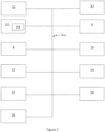
- An operator can control operation of the front and rear work units 6,8,10 from within the agricultural vehicle 4 by use of a suitable user terminal 30.
- the operator can cause each of the work units to move about the central frame a working position to a headland position, can cause each of the lateral work units 8,10 to move between the working position and the transport position.
- the operator can also control the working height of the lateral mowing units 8,10 within the ground adaptation range by use of the hydraulic units 22,24.
- the user terminal 30 communicates with an electronic control unit 32.
- the control unit 32 provides signals to control operation of the front and rear hitches 12,14 of the agricultural vehicle 4 and provides signals to control operation of the mowing units 6,8,10 and the conveyor units 16,18.
- the signals are provided by way of a suitable data communication network 40 such as one compliant with the ISOBUS standard (a network in conformance to ISO 11783).
- the control unit 32 may conveniently comprise a single processor located on the agricultural vehicle or its functions may be split between a processor located on the agricultural vehicle and one or more additional processors located on the mowing units 6,8,10, the additional processor(s) being in electronic communication with the first processor.
- the control unit 32 is also able to access a suitable memory 34.
- the memory 34 may take any suitable form and is in electronic communication with the control unit 32.
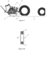
- Figure 3 shows operation of the agricultural apparatus 2 over level ground.
- Figure 3A shows the maximum upper and lower heights 36,38 of the lateral work units 8,10, that is the ground adaptation range of the lateral work units 8,10 in relation to the agricultural vehicle 4 when the hitch 14 is in the position 50 shown in Figure 3 .
- a predetermined reference value 60 for the desired displacement of the rear hitch 14 is shown to one side of Figure 3A .
- the predetermined reference value 60 is conveniently stored in the memory in any suitable manner such as a database or look up table. In the normal working position over level ground, the predetermined reference value 60 corresponds with the actual position 50 of the rear hitch 14.
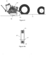
- Figure 4 shows the agricultural vehicle 4 in a raised position with respect to the lateral work units 8,10.
- the position or displacement of the rear hitch 14 is determined by the sensor 26 (step 202, Figure 6 ).
- Figure 4A shows the position 50 of the rear hitch 14 is below the predetermined reference value 60 but is within an acceptable region of the ground adaptation range of the lateral work units, 8,10.
- the difference between the position 50 of the hitch 14 and the predetermined reference value 60 is calculated (step 204). It is then determined whether this difference exceeds a predetermined threshold value (step 206)
- the control unit 32 may be programmed to take a number of actions as desired. For example if the difference between the position 50 of the rear hitch 14 and the predetermined reference value 60 is determined not to exceed the threshold value the control unit 32 takes no action to move the rear hitch 14 (step 208).
- the threshold value is conveniently also stored in the memory 34. For example if the difference between the position 50 of the hitch 14 and the predetermined reference value 60 is determined to exceed the predetermined threshold value the control unit 32 can take action to adjust the displacement of the rear hitch 14 (step 210).
- the control unit 32 can signal, either visually, audibly or both, to the operator of the agricultural vehicle 4 by way of the user terminal 30 that the first threshold value has been exceeded so that the operator can take action on their own judgement.
- Figure 5 shows the agricultural vehicle 4 raised further in relation to the lateral work units 8,10. As seen in Figure 5A the lateral work units 8,10 are now operating at or towards an edge of the ground adaptation range. This value or range of values can be defined as a second threshold value or values within the memory 34.
- Figure 7 shows the sequence of steps as the agricultural vehicle travels over an increasing gradient of slope (in Figure 7 steps 202 to 210 are similar to those shown in Figure 6 ). If no action is taken by the operator or the control unit when a first threshold value is encountered (step 208) the position of the rear hitch 14 continues to be compared to the first and second threshold values. In the event of the second threshold value being encountered the control unit 32 automatically causes the rear hitch 14 to be displaced without input from the operator (steps 212,214).
- the lateral work units 8,10 are once again i operation comfortably within the ground adaptation range and can more easily be adapted to a desirable working position by the hydraulic units 22,24.
- the rear hitch 14 is raised to the new hitch position such that the mower combination is adjusted to the new terrain by the time the lateral work units 8,10 arrive at the new terrain. In this way damage to the lateral work units 8,10 and/or contamination of the cut crop is avoided.
- control unit 32 may be programmed to alter the height of the rear hitch 24 toward the reference value 50 and if the second threshold value is then encountered the control unit 32 causes the rear hitch 14 to be moved more swiftly toward the reference value.
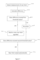
- a front sensor 42 is provided to detect the presence or absence of standing crop ahead of the agricultural apparatus 2.
- This front sensor 42 may be mounted on the agricultural vehicle 4 or the front work unit 6. Alternatively an aggregated signal from sensors 42 on both the agricultural vehicle 4 and the front work unit 6 may be used.
- the control unit 24 detects the signal from the front sensor 42 (step 300 Figure 11) and determines the presence or absence of standing crop head of the front work unit 6 (step 302).
- control unit 24 takes no action and the work units 6,8,10 continue to operate in the working position (step 304). If no standing crop is detected the control unit 24 causes the work units 6,8,10 to move to the headland positions (step 306). In this way the when the edge of the standing crop to be processed is reached, the agricultural implement is operated to reach the headland position as soon as possible.
- the front work unit 6 may first be moved to a headland position and the lateral work units 8,10 may be subsequently controlled to continue cutting the standing crop until the edge of the standing crop is reached and then the lateral work units 8,10 also are automatically raised to their headland position.
Landscapes
- Life Sciences & Earth Sciences (AREA)
- Environmental Sciences (AREA)
- Engineering & Computer Science (AREA)
- Mechanical Engineering (AREA)
- Soil Sciences (AREA)
- Harvester Elements (AREA)
- Agricultural Machines (AREA)
Claims (5)
- Mähwerkskombination mit einem landwirtschaftlichen Fahrzeug (4) im Verbund mit einer vorderen Arbeitseinheit (6) und zwei seitlichen Arbeitseinheiten (8, 10), die hinter und an den Seiten der vorderen Arbeitseinheit (6) verortet sind, wobei die vordere Arbeitseinheit (6) einen vorderen Anschluss (12) an eine Front des landwirtschaftlichen Fahrzeugs (4) aufweist und sich die seitlichen Arbeitseinheiten (8, 10) einen hinteren Anschluss (14) an eine Rückseite des landwirtschaftlichen Fahrzeugs (4) teilen, wobei jede der Arbeitseinheiten (6, 8, 10) geschnittenes Erntegut als ein Schwad (20) ablegt, mindestens einem Sensor (26) zum Bestimmen einer Höhe des hinteren Anschlusses (14) über einer Bodenoberfläche, einer Steuereinheit (32) zum Steuern einer Höhe der vorderen und hinteren Anschlüsse (12, 14) über einer Bodenoberfläche, dadurch gekennzeichnet, dass dann, wenn bestimmt wird, dass die Höhe des hinteren Anschlusses (14) von einem vorbestimmten Wert abweicht, die Steuereinheit (32) veranlasst, dass die Höhe des hinteren Anschlusses (14) zu dem vorgegebenen Wert hin korrigiert wird.
- Mähwerkskombination nach Anspruch 1, dadurch gekennzeichnet, dass die Mähwerkskombination einen weiteren Sensor (42) umfasst, um das Vorhandensein von Erntegut vor der vorderen Arbeitseinheit (6) zu detektieren und in dem Fall, dass kein Erntegut als vorhanden detektiert wird, die Steuereinheit (32) mindestens eine der Arbeitseinheiten (6, 8, 10) veranlasst, sich von der Arbeitsposition in die Vorgewendeposition zu bewegen.
- Verfahren zum Betrieb einer Mähwerkskombination nach Anspruch 1, dadurch gekennzeichnet, dass es die Schritte eines Bereitstellens eines vorbestimmten Satzes von Werten an die Steuereinheit (32), eines Bereitstellens von für die Position des hinteren Anschlusses (14) repräsentativen Signalen aufweist, wobei die Steuereinheit (32) die Signale, welche die Position des hinteren Anschlusses (14) repräsentieren, mit dem vorbestimmten Satz von Werten vergleicht und, falls erforderlich, signalisiert, dass der hintere Anschluss (14) basierend auf diesem Vergleich zu verschieben ist.
- Verfahren nach Anspruch 3, dadurch gekennzeichnet, dass das Verfahren weiterhin den Schritt eines Überwachens auf das Vorhandensein von stehendem Erntegut vor dem landwirtschaftlichen Fahrzeug (4) aufweist, und in dem Fall, dass kein Erntegut als vorhanden detektiert wird, die Steuereinheit (32) mindestens eine der Arbeitseinheiten (6, 8, 10) veranlasst, sich von einer Arbeitsposition in eine Vorgewendeposition zu bewegen.
- Computerlesbares Programm mit Instruktionen, welches, wenn das Programm auf einem Computer ausgeführt wird, die Mähwerkskombination nach Anspruch 1 oder Anspruch 2 veranlasst, das Verfahren nach Anspruch 3 oder Anspruch 4 auszuführen.
Applications Claiming Priority (1)
| Application Number | Priority Date | Filing Date | Title |
|---|---|---|---|
| GBGB2003487.2A GB202003487D0 (en) | 2020-03-11 | 2020-03-11 | Agricultural apparatus |
Publications (2)
| Publication Number | Publication Date |
|---|---|
| EP3878263A1 EP3878263A1 (de) | 2021-09-15 |
| EP3878263B1 true EP3878263B1 (de) | 2025-01-08 |
Family
ID=70453560
Family Applications (1)
| Application Number | Title | Priority Date | Filing Date |
|---|---|---|---|
| EP21153377.3A Active EP3878263B1 (de) | 2020-03-11 | 2021-01-26 | Mähwerkskombination |
Country Status (3)
| Country | Link |
|---|---|
| US (1) | US11882790B2 (de) |
| EP (1) | EP3878263B1 (de) |
| GB (1) | GB202003487D0 (de) |
Family Cites Families (20)
| Publication number | Priority date | Publication date | Assignee | Title |
|---|---|---|---|---|
| US3177638A (en) * | 1960-09-30 | 1965-04-13 | Arthur L Johnson | Wide swath mower convertible for highway travel |
| NL6716443A (de) * | 1967-12-04 | 1969-06-06 | ||
| US3731469A (en) * | 1972-01-24 | 1973-05-08 | Jacobsen Mfg Co | Convertible gang lawn mower |
| US4876845A (en) | 1989-04-12 | 1989-10-31 | Robert M. Torras | Self propelled mower and towed mower with adjustable height connection |
| US5069022A (en) * | 1990-09-28 | 1991-12-03 | Befco, Inc. | Gang mower apparatus |
| JPH07264913A (ja) | 1994-03-30 | 1995-10-17 | Kensetsusho Hokurikuchihou Kensetsukyoku | 草刈機の刈り高さ検出装置 |
| US5455769A (en) * | 1994-06-24 | 1995-10-03 | Case Corporation | Combine head raise and lower rate control |
| DE19959484A1 (de) * | 1999-12-10 | 2001-06-13 | Deere & Co | Mähgerät |
| FR2837347B1 (fr) * | 2002-03-21 | 2004-07-30 | Kuhn Sa | Faucheuse agricole comportant un vehicule porteur et plusieurs unites de travail |
| DE10247273C1 (de) * | 2002-10-10 | 2003-12-04 | Walterscheid Gmbh Gkn | Vorrichtung zum Regeln der Position eines Anbaugeräts relativ zu einem Trägerfahrzeug |
| US8688331B2 (en) * | 2009-12-18 | 2014-04-01 | Agco Corporation | Method to enhance performance of sensor-based implement height control |
| DE102012004045A1 (de) * | 2011-05-03 | 2012-12-06 | Claas Saulgau Gmbh | "Erntemaschine mit wenigstens einem Querförderer" |
| JP6123312B2 (ja) | 2013-01-30 | 2017-05-10 | 井関農機株式会社 | 乗用型芝刈り機 |
| ES2568757T5 (es) * | 2013-07-22 | 2024-12-10 | Kverneland Group Kerteminde As | Cortacésped |
| PL3162183T3 (pl) * | 2015-11-02 | 2022-01-10 | Maschinenfabrik Bermatingen Gmbh & Co. Kg | Kosiarka mulczująca |
| US10517207B2 (en) * | 2016-05-02 | 2019-12-31 | Cnh Industrial America Llc | Programmable one-touch raise feature for an agricultural harvester such as a windrower |
| EP3251484B1 (de) * | 2016-06-03 | 2018-09-26 | Kverneland Group Kerteminde A/S | Verfahren und vorrichtung zum betreiben einer landwirtschaftlichen maschine |
| NL2017043B1 (en) * | 2016-06-24 | 2018-01-19 | Forage Co Bv | An agricultural machine and a method for processing crop |
| US10806078B2 (en) * | 2017-05-12 | 2020-10-20 | Deere & Company | Control system for adjusting conditioning rollers of work vehicle |
| GB201905205D0 (en) * | 2019-04-12 | 2019-05-29 | Agco Feucht Gmbh | Agricultural implement |
-
2020
- 2020-03-11 GB GBGB2003487.2A patent/GB202003487D0/en not_active Ceased
-
2021
- 2021-01-26 EP EP21153377.3A patent/EP3878263B1/de active Active
- 2021-03-11 US US17/199,359 patent/US11882790B2/en active Active
Also Published As
| Publication number | Publication date |
|---|---|
| US11882790B2 (en) | 2024-01-30 |
| GB202003487D0 (en) | 2020-04-29 |
| EP3878263A1 (de) | 2021-09-15 |
| US20210282319A1 (en) | 2021-09-16 |
Similar Documents
| Publication | Publication Date | Title |
|---|---|---|
| EP3735123B1 (de) | Schneidwerk für erntemaschine | |
| EP3695703B1 (de) | Schwadmäher mit bodenkonturerfassungssystem und bodenkonturerfassungsmethode | |
| EP3122169B1 (de) | Steuerung von schnitthöhe und -winkel eines mähdrescherschneidwerks | |
| EP2695511B1 (de) | System zur Höhensteuerung eines Vorsatzgeräts | |
| EP3878262A1 (de) | Landwirtschaftliche vorrichtung | |
| US20140215983A1 (en) | Self-propelled agricultural harvesting machine | |
| KR20210137864A (ko) | 전방센서부를 이용한 장애물 회피기능을 가진 농업용 예초시스템 | |
| EP3879961B1 (de) | System und verfahren zur einstellung von parametern für einen landwirtschaftlichen erntevorsatz aus mehreren segmenten | |
| EP3878267B1 (de) | Mähvorrichtung | |
| EP3837952B1 (de) | Mähkombination | |
| EP3878263B1 (de) | Mähwerkskombination | |
| EP3837953B1 (de) | Landwirtschaftliche vorrichtung | |
| EP3837954B1 (de) | Mähvorrichtung | |
| EP4014709A1 (de) | Landwirtschaftliche vorrichtung mit schnitthöhenregelung | |
| EP3878264B1 (de) | Landwirtschaftliche vorrichtung | |
| EP3837956B1 (de) | Mähvorrichtung | |
| US11778949B2 (en) | Mower combination with location based conveyor control | |
| JP2955439B2 (ja) | 刈取収穫機の刈高さ制御装置 | |
| EP3902385B1 (de) | Vorrichtung zum einschalten und ausschalten der leistungsübertragung in einem fahrzeug mit über ein kardangelenk operativ verbundenem anhänger | |
| JP2001224216A (ja) | コンバインにおける補助刈刃装置の姿勢制御装置 | |
| JPH06319337A (ja) | 刈取収穫機の刈高さ制御装置 | |
| JP2023033981A (ja) | 収穫機械の制御方法、収穫機械用制御プログラム、収穫機械用制御システム及び収穫機械 |
Legal Events
| Date | Code | Title | Description |
|---|---|---|---|
| PUAI | Public reference made under article 153(3) epc to a published international application that has entered the european phase |
Free format text: ORIGINAL CODE: 0009012 |
|
| STAA | Information on the status of an ep patent application or granted ep patent |
Free format text: STATUS: THE APPLICATION HAS BEEN PUBLISHED |
|
| AK | Designated contracting states |
Kind code of ref document: A1 Designated state(s): AL AT BE BG CH CY CZ DE DK EE ES FI FR GB GR HR HU IE IS IT LI LT LU LV MC MK MT NL NO PL PT RO RS SE SI SK SM TR |
|
| STAA | Information on the status of an ep patent application or granted ep patent |
Free format text: STATUS: REQUEST FOR EXAMINATION WAS MADE |
|
| 17P | Request for examination filed |
Effective date: 20220315 |
|
| RBV | Designated contracting states (corrected) |
Designated state(s): AL AT BE BG CH CY CZ DE DK EE ES FI FR GB GR HR HU IE IS IT LI LT LU LV MC MK MT NL NO PL PT RO RS SE SI SK SM TR |
|
| P01 | Opt-out of the competence of the unified patent court (upc) registered |
Effective date: 20230518 |
|
| GRAP | Despatch of communication of intention to grant a patent |
Free format text: ORIGINAL CODE: EPIDOSNIGR1 |
|
| STAA | Information on the status of an ep patent application or granted ep patent |
Free format text: STATUS: GRANT OF PATENT IS INTENDED |
|
| RIC1 | Information provided on ipc code assigned before grant |
Ipc: A01B 63/111 20060101ALI20240924BHEP Ipc: A01D 75/30 20060101ALI20240924BHEP Ipc: A01D 34/74 20060101ALI20240924BHEP Ipc: A01D 34/66 20060101AFI20240924BHEP |
|
| INTG | Intention to grant announced |
Effective date: 20241014 |
|
| GRAS | Grant fee paid |
Free format text: ORIGINAL CODE: EPIDOSNIGR3 |
|
| GRAA | (expected) grant |
Free format text: ORIGINAL CODE: 0009210 |
|
| STAA | Information on the status of an ep patent application or granted ep patent |
Free format text: STATUS: THE PATENT HAS BEEN GRANTED |
|
| AK | Designated contracting states |
Kind code of ref document: B1 Designated state(s): AL AT BE BG CH CY CZ DE DK EE ES FI FR GB GR HR HU IE IS IT LI LT LU LV MC MK MT NL NO PL PT RO RS SE SI SK SM TR |
|
| REG | Reference to a national code |
Ref country code: GB Ref legal event code: FG4D |
|
| REG | Reference to a national code |
Ref country code: CH Ref legal event code: EP |
|
| REG | Reference to a national code |
Ref country code: DE Ref legal event code: R096 Ref document number: 602021024542 Country of ref document: DE |
|
| REG | Reference to a national code |
Ref country code: IE Ref legal event code: FG4D |
|
| PGFP | Annual fee paid to national office [announced via postgrant information from national office to epo] |
Ref country code: AT Payment date: 20250417 Year of fee payment: 5 |
|
| REG | Reference to a national code |
Ref country code: LT Ref legal event code: MG9D |
|
| REG | Reference to a national code |
Ref country code: NL Ref legal event code: MP Effective date: 20250108 |
|
| REG | Reference to a national code |
Ref country code: AT Ref legal event code: MK05 Ref document number: 1757689 Country of ref document: AT Kind code of ref document: T Effective date: 20250108 |
|
| PG25 | Lapsed in a contracting state [announced via postgrant information from national office to epo] |
Ref country code: NL Free format text: LAPSE BECAUSE OF FAILURE TO SUBMIT A TRANSLATION OF THE DESCRIPTION OR TO PAY THE FEE WITHIN THE PRESCRIBED TIME-LIMIT Effective date: 20250108 |
|
| PG25 | Lapsed in a contracting state [announced via postgrant information from national office to epo] |
Ref country code: RS Free format text: LAPSE BECAUSE OF FAILURE TO SUBMIT A TRANSLATION OF THE DESCRIPTION OR TO PAY THE FEE WITHIN THE PRESCRIBED TIME-LIMIT Effective date: 20250408 |
|
| PG25 | Lapsed in a contracting state [announced via postgrant information from national office to epo] |
Ref country code: FI Free format text: LAPSE BECAUSE OF FAILURE TO SUBMIT A TRANSLATION OF THE DESCRIPTION OR TO PAY THE FEE WITHIN THE PRESCRIBED TIME-LIMIT Effective date: 20250108 |
|
| PG25 | Lapsed in a contracting state [announced via postgrant information from national office to epo] |
Ref country code: PL Free format text: LAPSE BECAUSE OF FAILURE TO SUBMIT A TRANSLATION OF THE DESCRIPTION OR TO PAY THE FEE WITHIN THE PRESCRIBED TIME-LIMIT Effective date: 20250108 |
|
| PG25 | Lapsed in a contracting state [announced via postgrant information from national office to epo] |
Ref country code: ES Free format text: LAPSE BECAUSE OF FAILURE TO SUBMIT A TRANSLATION OF THE DESCRIPTION OR TO PAY THE FEE WITHIN THE PRESCRIBED TIME-LIMIT Effective date: 20250108 |
|
| PG25 | Lapsed in a contracting state [announced via postgrant information from national office to epo] |
Ref country code: IS Free format text: LAPSE BECAUSE OF FAILURE TO SUBMIT A TRANSLATION OF THE DESCRIPTION OR TO PAY THE FEE WITHIN THE PRESCRIBED TIME-LIMIT Effective date: 20250508 Ref country code: NO Free format text: LAPSE BECAUSE OF FAILURE TO SUBMIT A TRANSLATION OF THE DESCRIPTION OR TO PAY THE FEE WITHIN THE PRESCRIBED TIME-LIMIT Effective date: 20250408 |
|
| PG25 | Lapsed in a contracting state [announced via postgrant information from national office to epo] |
Ref country code: HR Free format text: LAPSE BECAUSE OF FAILURE TO SUBMIT A TRANSLATION OF THE DESCRIPTION OR TO PAY THE FEE WITHIN THE PRESCRIBED TIME-LIMIT Effective date: 20250108 |
|
| PG25 | Lapsed in a contracting state [announced via postgrant information from national office to epo] |
Ref country code: LV Free format text: LAPSE BECAUSE OF FAILURE TO SUBMIT A TRANSLATION OF THE DESCRIPTION OR TO PAY THE FEE WITHIN THE PRESCRIBED TIME-LIMIT Effective date: 20250108 Ref country code: PT Free format text: LAPSE BECAUSE OF FAILURE TO SUBMIT A TRANSLATION OF THE DESCRIPTION OR TO PAY THE FEE WITHIN THE PRESCRIBED TIME-LIMIT Effective date: 20250508 |
|
| PG25 | Lapsed in a contracting state [announced via postgrant information from national office to epo] |
Ref country code: BG Free format text: LAPSE BECAUSE OF FAILURE TO SUBMIT A TRANSLATION OF THE DESCRIPTION OR TO PAY THE FEE WITHIN THE PRESCRIBED TIME-LIMIT Effective date: 20250108 Ref country code: GR Free format text: LAPSE BECAUSE OF FAILURE TO SUBMIT A TRANSLATION OF THE DESCRIPTION OR TO PAY THE FEE WITHIN THE PRESCRIBED TIME-LIMIT Effective date: 20250409 |
|
| PG25 | Lapsed in a contracting state [announced via postgrant information from national office to epo] |
Ref country code: AT Free format text: LAPSE BECAUSE OF FAILURE TO SUBMIT A TRANSLATION OF THE DESCRIPTION OR TO PAY THE FEE WITHIN THE PRESCRIBED TIME-LIMIT Effective date: 20250108 |
|
| REG | Reference to a national code |
Ref country code: CH Ref legal event code: PL |
|
| PG25 | Lapsed in a contracting state [announced via postgrant information from national office to epo] |
Ref country code: SE Free format text: LAPSE BECAUSE OF FAILURE TO SUBMIT A TRANSLATION OF THE DESCRIPTION OR TO PAY THE FEE WITHIN THE PRESCRIBED TIME-LIMIT Effective date: 20250108 |
|
| PG25 | Lapsed in a contracting state [announced via postgrant information from national office to epo] |
Ref country code: LU Free format text: LAPSE BECAUSE OF NON-PAYMENT OF DUE FEES Effective date: 20250126 |
|
| PG25 | Lapsed in a contracting state [announced via postgrant information from national office to epo] |
Ref country code: SM Free format text: LAPSE BECAUSE OF FAILURE TO SUBMIT A TRANSLATION OF THE DESCRIPTION OR TO PAY THE FEE WITHIN THE PRESCRIBED TIME-LIMIT Effective date: 20250108 |
|
| REG | Reference to a national code |
Ref country code: DE Ref legal event code: R097 Ref document number: 602021024542 Country of ref document: DE |
|
| PG25 | Lapsed in a contracting state [announced via postgrant information from national office to epo] |
Ref country code: DK Free format text: LAPSE BECAUSE OF FAILURE TO SUBMIT A TRANSLATION OF THE DESCRIPTION OR TO PAY THE FEE WITHIN THE PRESCRIBED TIME-LIMIT Effective date: 20250108 |
|
| PG25 | Lapsed in a contracting state [announced via postgrant information from national office to epo] |
Ref country code: MC Free format text: LAPSE BECAUSE OF FAILURE TO SUBMIT A TRANSLATION OF THE DESCRIPTION OR TO PAY THE FEE WITHIN THE PRESCRIBED TIME-LIMIT Effective date: 20250108 |
|
| PG25 | Lapsed in a contracting state [announced via postgrant information from national office to epo] |
Ref country code: CH Free format text: LAPSE BECAUSE OF NON-PAYMENT OF DUE FEES Effective date: 20250131 |
|
| PG25 | Lapsed in a contracting state [announced via postgrant information from national office to epo] |
Ref country code: CZ Free format text: LAPSE BECAUSE OF FAILURE TO SUBMIT A TRANSLATION OF THE DESCRIPTION OR TO PAY THE FEE WITHIN THE PRESCRIBED TIME-LIMIT Effective date: 20250108 Ref country code: EE Free format text: LAPSE BECAUSE OF FAILURE TO SUBMIT A TRANSLATION OF THE DESCRIPTION OR TO PAY THE FEE WITHIN THE PRESCRIBED TIME-LIMIT Effective date: 20250108 |
|
| PG25 | Lapsed in a contracting state [announced via postgrant information from national office to epo] |
Ref country code: RO Free format text: LAPSE BECAUSE OF FAILURE TO SUBMIT A TRANSLATION OF THE DESCRIPTION OR TO PAY THE FEE WITHIN THE PRESCRIBED TIME-LIMIT Effective date: 20250108 |
|
| PG25 | Lapsed in a contracting state [announced via postgrant information from national office to epo] |
Ref country code: SK Free format text: LAPSE BECAUSE OF FAILURE TO SUBMIT A TRANSLATION OF THE DESCRIPTION OR TO PAY THE FEE WITHIN THE PRESCRIBED TIME-LIMIT Effective date: 20250108 |
|
| PLBE | No opposition filed within time limit |
Free format text: ORIGINAL CODE: 0009261 |
|
| STAA | Information on the status of an ep patent application or granted ep patent |
Free format text: STATUS: NO OPPOSITION FILED WITHIN TIME LIMIT |
|
| 26N | No opposition filed |
Effective date: 20251009 |
|
| GBPC | Gb: european patent ceased through non-payment of renewal fee |
Effective date: 20250408 |
|
| PG25 | Lapsed in a contracting state [announced via postgrant information from national office to epo] |
Ref country code: GB Free format text: LAPSE BECAUSE OF NON-PAYMENT OF DUE FEES Effective date: 20250408 |
|
| PG25 | Lapsed in a contracting state [announced via postgrant information from national office to epo] |
Ref country code: IT Free format text: LAPSE BECAUSE OF FAILURE TO SUBMIT A TRANSLATION OF THE DESCRIPTION OR TO PAY THE FEE WITHIN THE PRESCRIBED TIME-LIMIT Effective date: 20250108 |
|
| PGFP | Annual fee paid to national office [announced via postgrant information from national office to epo] |
Ref country code: IE Payment date: 20260122 Year of fee payment: 6 Ref country code: DE Payment date: 20260121 Year of fee payment: 6 |
|
| PGFP | Annual fee paid to national office [announced via postgrant information from national office to epo] |
Ref country code: BE Payment date: 20260121 Year of fee payment: 6 |
|
| PGFP | Annual fee paid to national office [announced via postgrant information from national office to epo] |
Ref country code: FR Payment date: 20260123 Year of fee payment: 6 |