EP3877779B1 - Integrierte kühllösung für spinnsensoren - Google Patents
Integrierte kühllösung für spinnsensoren Download PDFInfo
- Publication number
- EP3877779B1 EP3877779B1 EP19900062.1A EP19900062A EP3877779B1 EP 3877779 B1 EP3877779 B1 EP 3877779B1 EP 19900062 A EP19900062 A EP 19900062A EP 3877779 B1 EP3877779 B1 EP 3877779B1
- Authority
- EP
- European Patent Office
- Prior art keywords
- sensor housing
- sensor
- air
- housing
- interior
- Prior art date
- Legal status (The legal status is an assumption and is not a legal conclusion. Google has not performed a legal analysis and makes no representation as to the accuracy of the status listed.)
- Active
Links
Images





Classifications
-
- G—PHYSICS
- G01—MEASURING; TESTING
- G01D—MEASURING NOT SPECIALLY ADAPTED FOR A SPECIFIC VARIABLE; ARRANGEMENTS FOR MEASURING TWO OR MORE VARIABLES NOT COVERED IN A SINGLE OTHER SUBCLASS; TARIFF METERING APPARATUS; MEASURING OR TESTING NOT OTHERWISE PROVIDED FOR
- G01D11/00—Component parts of measuring arrangements not specially adapted for a specific variable
- G01D11/24—Housings ; Casings for instruments
-
- G—PHYSICS
- G01—MEASURING; TESTING
- G01D—MEASURING NOT SPECIALLY ADAPTED FOR A SPECIFIC VARIABLE; ARRANGEMENTS FOR MEASURING TWO OR MORE VARIABLES NOT COVERED IN A SINGLE OTHER SUBCLASS; TARIFF METERING APPARATUS; MEASURING OR TESTING NOT OTHERWISE PROVIDED FOR
- G01D11/00—Component parts of measuring arrangements not specially adapted for a specific variable
- G01D11/24—Housings ; Casings for instruments
- G01D11/245—Housings for sensors
-
- G—PHYSICS
- G01—MEASURING; TESTING
- G01D—MEASURING NOT SPECIALLY ADAPTED FOR A SPECIFIC VARIABLE; ARRANGEMENTS FOR MEASURING TWO OR MORE VARIABLES NOT COVERED IN A SINGLE OTHER SUBCLASS; TARIFF METERING APPARATUS; MEASURING OR TESTING NOT OTHERWISE PROVIDED FOR
- G01D21/00—Measuring or testing not otherwise provided for
-
- G—PHYSICS
- G01—MEASURING; TESTING
- G01S—RADIO DIRECTION-FINDING; RADIO NAVIGATION; DETERMINING DISTANCE OR VELOCITY BY USE OF RADIO WAVES; LOCATING OR PRESENCE-DETECTING BY USE OF THE REFLECTION OR RERADIATION OF RADIO WAVES; ANALOGOUS ARRANGEMENTS USING OTHER WAVES
- G01S17/00—Systems using the reflection or reradiation of electromagnetic waves other than radio waves, e.g. lidar systems
- G01S17/88—Lidar systems specially adapted for specific applications
- G01S17/93—Lidar systems specially adapted for specific applications for anti-collision purposes
- G01S17/931—Lidar systems specially adapted for specific applications for anti-collision purposes of land vehicles
-
- G—PHYSICS
- G01—MEASURING; TESTING
- G01S—RADIO DIRECTION-FINDING; RADIO NAVIGATION; DETERMINING DISTANCE OR VELOCITY BY USE OF RADIO WAVES; LOCATING OR PRESENCE-DETECTING BY USE OF THE REFLECTION OR RERADIATION OF RADIO WAVES; ANALOGOUS ARRANGEMENTS USING OTHER WAVES
- G01S7/00—Details of systems according to groups G01S13/00, G01S15/00, G01S17/00
- G01S7/48—Details of systems according to groups G01S13/00, G01S15/00, G01S17/00 of systems according to group G01S17/00
- G01S7/481—Constructional features, e.g. arrangements of optical elements
- G01S7/4811—Constructional features, e.g. arrangements of optical elements common to transmitter and receiver
- G01S7/4813—Housing arrangements
Definitions
- Autonomous vehicles for instance, vehicles that do not require a human driver, can be used to aid in the transport of passengers or items from one location to another. Such vehicles may operate in a fully autonomous mode where passengers may provide some initial input, such as a pickup or destination location, and the vehicle maneuvers itself to that location without the need for additional input from the passenger or any other human. Thus, such vehicles may be used to provide transportation services.
- vehicles such as cars, trucks, motorcycles, busses, boats, airplanes, helicopters, lawn mowers, recreational vehicles, amusement park vehicles, farm equipment, construction equipment, trams, golf carts, trains, trolleys, etc.
- vehicles such as autonomous vehicles, may include sensors such as LIDAR, radar, sonar, camera, or other such imaging sensors that scan and record data from the vehicle's environment. Sensor data from one or more of these sensors may be used to detect objects and their respective characteristics (position, shape, heading, speed, etc.).
- the sensors may be adversely affected by the buildup of heat within the sensor itself.
- the sensors include a housing to protect the internal sensor components of the sensors from debris and contaminants, but over time, the housing may trap solar heat, as well as heat generated by the various internal components of the sensor. As such, the sensor components may be subjected to sub-optimal temperature conditions during operation.
- US 2018/334109 A1 describes a device for protecting an optical sensor of a driver-assistance system for a motor vehicle, a corresponding driver-assistance system and a corresponding assembling process.
- the optical sensor includes an optic and two assembled separate subassemblies.
- a first subassembly is mounted so as to be able to rotate about an axis of rotation and includes a housing that is configured to at least partially receive the optical sensor and an optical element that is configured to be placed upstream of the optic of the optical sensor.
- a second subassembly includes an actuator that is configured to drive the first subassembly to rotate.
- the main vent may be positioned on a top portion of the sensor housing.
- the side vent may positioned on a side wall of the sensor housing closer to a base portion of the sensor housing than the top portion.
- the main vent may be positioned on a base portion of the sensor housing.
- the side vent may be positioned on a side wall of the sensor housing closer to a top portion of the sensor housing than the bottom portion.
- the system may further comprise one or more guide blades fixed relative to the sensor housing, wherein the one or more guide blades are configured to force the air pulled into the interior portion of the sensor housing radially outward from the axis.
- the motor may be configured to rotate the one or more guide blades to force the air pulled into the interior portion of the sensor housing radially outward from the axis.
- the system may further comprise one or more contoured blades fixed relative to the sensor housing, wherein the one or more contoured blades are configured to force the air pulled into the interior portion of the sensor housing through the side vent.
- the motor may be configured to rotate the one or more contoured blades to force the air pulled into the interior portion of the sensor housing through the side vent.
- the system may further comprise one or more guide blades and one or more contoured blades.
- the one or more guide blades may be straight and the one or more contoured blades may be curved.
- the senor may be mounted to a vehicle.
- system may further include the vehicle.
- the system may further comprise an interior channel within the sensor housing connected to the exhaust vent (side vent).
- the air pulled into the interior portion of the sensor housing may flow through the interior channel to the exhaust vent.
- system may further comprise one or more guide blades, wherein the one or more guide blades are configured to force the air pulled into the interior portion of the sensor housing radially outward from the axis.
- the system may further comprise one or more contoured blades, wherein the one or more contoured blades are configured to force the air pulled into the interior portion of the sensor housing through the interior channel and out of the exhaust vent.
- the system may further comprise a vehicle, wherein the sensor is mounted to the vehicle.
- a sensor may be comprised of internal sensor components, such as sensors and processors, and housing.
- the housing may protect the internal sensor components and processors from elements, such as rain, snow, dust and other such debris.
- operation of the internal sensors components, processors, and solar energy may result in excessive heat within the housing. Such excessive heat may prematurely degrade the internal sensor components and processors and possibly overheat the processors making them inoperable.
- a convective air flow may be passed through the sensor housing.
- the rotation of the sensor housing may generate a force which pulls cool air located externally from the sensor into the interior of the sensor housing.
- the cool, pulled in air may be directed across the sensor's internal components, thereby drawing heat away from the sensor's internal components.
- the heated air may then be directed out of the sensor housing.
- a vehicle may have one or more sensors to detect objects external to the vehicle such as other vehicles, obstacles in the roadway, traffic signals, signs, trees, etc.
- the vehicle 101 may include lasers, sonar, radar, cameras and/or any other detection devices that capture images and record data which may be processed by computing devices within the vehicle.
- the vehicle's sensors such as LIDAR, radar, cameras, sonar, or other such imaging sensors, may capture images and detect objects and their characteristics such as location, orientation, size, shape, type, direction and speed of movement, etc.
- Images may include the raw (i.e., unprocessed) data captured by the sensors and/or pictures and videos captured by camera sensors.
- Images may also include processed raw data. For instance, the raw data from the sensors and/or the aforementioned characteristics can be quantified or arranged into a descriptive function or vector for processing by the computing devices.
- the images may be analyzed to determine the vehicle's location, and to detect and respond to objects when needed.
- the sensors may be arranged around the vehicle's exterior or interior.
- housings 130, 140, 142, 150, 152 may include, for example, one or more LIDAR devices.
- the sensors may also be incorporated into the typical vehicle components, such as tail lights/turn signal lights 104 and/or side view mirrors 108.
- one or more laser, radar, sonar, camera and/or other such imaging sensors may be mounted on the roof, such as in housing 122, attached to mount 120.
- a vehicle sensor may be comprised of internal sensor components and a housing for housing the internal sensor components.
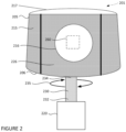
- the sensor housing is shown in the shape of a frustum, the sensor housing may be configured in various shapes and sizes, such as spheres, cylinders, cuboids, cones, prisms, pyramids, cubes, etc., or any combination of such shapes.
- the sensor housing 215 may be comprised of materials such as plastic, glass, polycarbonate, polystyrene, acrylic, polyester, etc.
- the sensor housing may include a housing window constructed at a certain location on the sensor housing such that the internal sensor components may transmit and receive one or more signals through the housing window.
- the side wall 205 of the sensor housing 215 may include a flat portion 226 in which housing window 216 is incorporated to allow signals (not shown) from internal sensor components 260 to penetrate the sensor cover 215, as further shown in Fig. 2 .
- the housing window 216 is shown as being circular in Fig. 2 , various other shapes may also be used for the housing window.
- the housing window may be incorporated onto non-flat surfaces of the housing.
- the entire sensor housing 215, or a large portion of the sensor housing 215, may be penetrable by the signals transmitted and received by the internal sensor components, thereby allowing a large portion or the entire sensor housing 215 to function as a housing window.
- the housing window 216 is shown as being only a portion of the side wall 205, in some instances the entire side wall 205 may be constructed as a housing window. Further, multiple housing windows may be positioned on the sensor housing 215.
- the housing window 216 may be composed of the same, or different, material as the sensor housing 215.
- the sensor 201 and/or sensor housing 215 may be attached to a motor via a sensor shaft.
- the sensor shaft 230 may include a first end 232 and a second end 234.
- the first end of the of a sensor shaft 232 may be attached to a sensor motor 220 and the second end of the sensor shaft 234 may be connected to the sensor 201 and/or sensor cover 215, such as at the base portion 206 of the sensor cover.
- the first end of the sensor shaft 232 may be attached to the motor 220 via a belt, gear, chain, friction roller, etc.
- the motor 220 may rotate the sensor shaft 230 in the first direction 235 causing the entire sensor 201 and/or sensor housing 215 to also rotate in the first direction 235.
- the sensor shaft 230 may only rotate the sensor housing 215, and not the internal components 260 of the sensor.
- the sensor 201, sensor housing 215, and/or motor 220 may each be located internally or externally from a vehicle.
- Fig. 2 shows the sensor 201 being attached to the motor 220 via a shaft 230, the motor 220 may be integrated or otherwise directly connected to the sensor 201 and/or sensor housing 215.
- the sensor housing includes a main vent through which air may flow into the interior of the sensor housing.
- the main vent is be positioned in a location where a pressure differential between the air located externally from the sensor housing and the air within the interior of the sensor housing occurs, such as on or near the axis of rotation of the sensor housing.
- the pressure differential is formed by the force generated by the rotation of the sensor housing lowering the pressure within the sensor housing relative to the air outside of the sensor housing. In this regard, the force increases the pressure the further outwards the air flows. Accordingly, a low pressure is generated near the axis of rotation and a high pressure is generated towards the perimeter where the side vents, described herein, are located.
- a sensor housing may include two or more main vents. The pressure differential may cause air to flow through the main vent into the lower pressure interior of the sensor housing.
- sensor 301 shown in Fig. 3 and which may be compared to sensor 201 includes a main vent 320 positioned on the sensor housing 315 at the center of the top portion 317.
- the main vent 320 is positioned on the axis of rotation, illustrated by line 326, of sensor 301 as it moves in a first direction, illustrated by arrow 327. Air may pass from the higher pressure location outside of the sensor housing 315, through the main vent 320, to the lower pressure locations in the interior of the sensor housing caused by the rotation of the sensor housing 315, as illustrated by arrow 370.
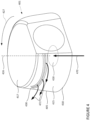
- sensor 401 shown in Fig. 4 and which may be compared to sensors 201 and/or 301 includes a main vent 420 positioned on the sensor housing 415 in the center of the base portion 418.
- the main vent 420 is positioned on the axis of rotation, illustrated by line 426, of sensor 401 as it moves in a first direction, illustrated by arrow 427.
- sensor 301 shows the main vent 320 as being centered on the top portion 317 and sensor 401 shows the main vent being centered on the base portion 418
- the main vent may be offset from the axis of rotation. Air may pass from the higher pressure location outside of the sensor housing 415, through the main vent 420, to lower pressure locations in the interior of the sensor housing caused by the rotation of the sensor housing 415, as illustrated by arrow 470.
- the main vent may include a permeable cover which allows air to pass into the interior of the sensor housing while at the same time blocking particles and debris from entering into the interior of the sensor housing.
- a filter may be positioned in or near the main vent to filter out particles and debris from the cool air which is pulled into the interior of the sensor housing.
- main vent 320 of sensor 301 includes a filter cover 321 to block particles and debris from traveling through the main vent 320.
- Side vents may be positioned on the sensor housing to vent air to the exterior of the sensor housing.
- the side vents may be one or more openings in the sensor housing which are configured to allow air to flow from high pressure locations within the interior of the sensor housing to lower pressure locations outside of the sensor housing.
- the side vents may include one or more covers, louvers, and/or filters which may prevent particles from passing through the sensor housing.
- the side vents may be positioned at a location on the sensor housing where air vented out of the sensor housing is directed away from the sensor housing's main vent to avoid recirculating air through the sensor housing.
- the side vents may be positioned at a location that vents the air in a radial direction relative to the main vent.
- side vents 330 are positioned on the side wall 305 near the base portion 318 of the sensor housing 315 when the main vent 320 is on the top portion 317 of the sensor 301. Air from within the sensor housing 315 may be output through the side vents 330 in a direction radial direction relative to the main vent 320, as illustrated by arrows 372.
- side vents 430 may be positioned on the side wall 405 near the top portion 417 when the main vent 420 is on the base portion 418 of the sensor 401. Air from within the sensor housing may be output through the side vents 430 in a direction radial direction relative to the main vent 420, as illustrated by arrows 472.
- Guide blades may be positioned and mounted, or otherwise integrated, into the interior of the sensor housing.
- the guide blades may be positioned around the axis of rotation of the sensor to move air away from the main vent to other portions of the interior of the sensor housing.
- the guide blades may remain fixed relative to the housing.
- the rotation of the guide blades and the sensor housing may be at same rate and/or the guide blades may be permanently attached to the sensor housing.
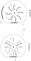
- the guide blades 511 may be positioned around the axis of rotation 326. In the cut-away bottom view of sensor 401 shown in Fig.
- the guide blades may be positioned around the axis of rotation 426.
- a single guide blade in each sensor i.e., sensor 301 and 401, is labeled in Figs. 5A and 6A .
- the guide blades may be positioned anywhere within the sensor housing. However, the further radially outward the guide blades are positioned from the axis of rotation the more effective they may be at moving air away from the axis of rotation. In this regard, as the sensor housing rotates, the guide blades may also rotate forcing the air within the sensor housing to move in a radial direction away from the axis of rotation towards the side wall of the sensor. For example, and as illustrated in Fig. 5A , guide blades 511 may force air within sensor housing 315 radially outward as illustrated by arrows 512. Similarly, guide blades 611 may force air within sensor housing 415 radially outward as illustrated by arrows 612.
- the change in pressure the guide blades produce may increase the further outwards from the axis of rotation they extend. As such, the further the guide blades are positioned from the axis of rotation, the greater the change in pressure the guide blades may produce.
- the guide blades e.g., 511 and 611,
- the guide blades may have contours, such as curves.
- Contoured blades may be positioned and mounted, or otherwise integrated, into the interior of the sensor housing to force warmed air out of the sensor housing.
- one or more contoured blades may be mounted near the side vents to force warm air from within the sensor housing to a location outside of the sensor housing.
- the contoured blades 521 may be positioned around the axis of rotation 326.
- the contoured blades 621 may be positioned around the axis of rotation 426.
- a single contoured blade in each sensor i.e., sensor 301 and 401, is labeled in Figs. 5B and 6B .
- the contoured blades e.g., 521 and 621, are illustrated as being straight, the guide blades may have contours, such as curves.
- the rotation of the sensor housing may also rotate the guide blades and contoured blades to generate an airflow through the sensor housing.
- the rotation of the sensor housing may generate a force which pulls cool air located externally from the sensor into the interior of the sensor housing.
- the cool, pulled in air may be forced across the sensor's internal components by the rotation of the guide blades. Through convection, the air travelling past the internal sensor components may draw heat away from the internal components. The heated air may then be directed out of the sensor housing by the rotation of the contoured blades.
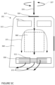
- Fig. 5C illustrates airflow through sensor 301 which includes a main vent 320 located on the top portion 317 of the sensor housing 315.
- a force is generated which may pull cool air downward and through the main vent 320, as illustrated by arrow 370.
- the rotation of the guide blades 511 may force the cool air across the internal sensor components 360, as illustrated by arrows 371.
- the cool air passing across the internal sensor components 360 may draw heat away from the internal sensor components 360.
- the rotation of the contoured blades 521 may then force the warmed air out of the sensor housing 315 through the side vents 330.
- Fig. 6C illustrates airflow through sensor 401 which includes a main vent 420 located on the base portion 418 of the sensor housing 315.
- a force is generated which may pull cool air in and upwards through the main vent 420, as illustrated by arrow 470.
- the rotation of the guide blades 611 may force the cool air across the internal sensor components 460, as illustrated by arrows 471.
- the cool air passing across the internal sensor components 460 may draw heat away from the internal sensor components 360.
- the rotation of the contoured blades 621 may then force the warmed air out of the sensor housing 415 through the side vents 430.
- the path of the air within the sensor housing may be controlled as the air flows through the sensor housing.
- the sensor housing may include one or more channels through which the flow may travel.
- the flow of air may be controlled, such that it can be directed to certain locations within the sensor housing, such as past internal sensor components which may requiring cooling.
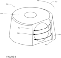
- sensor 701 which may be compared to sensors 201, 301, and 401, may include a main vent 720 on the top portion (not shown to allow the interior of the sensor housing to be shown) of sensor housing 715.
- a channel 780 which provides a controlled path through which air may flow.
- the rotation of the sensor 701 in the first direction illustrated by arrow 727, along with the rotation of the contoured blades 721 positioned within the sensor housing 715, may force air, illustrated as dashed line 781, into channel 780.
- the air 781 may flow through the channel 780 and out of the sensor housing at output 790. In some instances, the air may flow through the channel 780 to targeted locations within the sensor housing.
- the heated air may be exhausted past the housing window or other portions of the sensor housing to prevent particle buildup.
- the sensor housing and/or housing window may become covered by particles such as water, dust, dirt, condensation, or other such elements and debris, over time.
- the functions of the internal sensor components may be impeded as signals transmitted and received by the internal sensor components may be blocked by the buildup of particles.
- a spoiler edge having a vent may be incorporated into or attached to the sensor housing.
- the spoiler edge 752 may be positioned adjacent to the housing window 716 and configured such that the spoiler edge 752 extends away from the housing window 716 and/or sensor housing 715.
- the spoiler edge 311 may be positioned such that the spoiler edge is at a leading position relative to the sensor window during rotation in the first direction 727.
- the spoiler edge may include a vent 792 through which warmed air from the interior of the sensor can be output.
- Warmed air output through the vent 792 may be output across the face of the housing window, as illustrated by arrows 793, to prevent the particles from building up on areas of the sensor housing where signals may be transmitted and/or received.
- Vent 792 may be used in lieu of, or in conjunction with side vents, such as side vents 330.
- Figs. 7 and 8 illustrate the main vent positioned on the top portion 790 of sensor 701, the main vent may be positioned on the bottom portion of the sensor.
- a convective airflow may provide cooling for components within the sensor housing.
- the heat generated by the sensor components in sensor housing, as well as the heat generated by solar radiation may be effectively removed.
- guide blades and contoured blades within the sensor housing air is able to be moved across the surface of the internal sensor components without the need for a fan. As a fan is not required to cool the sensor components, noise and vibration introduced by a fan is avoided.
- fewer mover parts are required to cool the interior of the sensor housing, thereby decreasing the number of potential failure points of the cooling system.
- the guide inlet blades and contoured blades do not require an additional power source.
Landscapes
- Physics & Mathematics (AREA)
- General Physics & Mathematics (AREA)
- Engineering & Computer Science (AREA)
- Computer Networks & Wireless Communication (AREA)
- Radar, Positioning & Navigation (AREA)
- Remote Sensing (AREA)
- Electromagnetism (AREA)
- Cooling Or The Like Of Electrical Apparatus (AREA)
- Air-Conditioning For Vehicles (AREA)
- Studio Devices (AREA)
Claims (15)
- System zum Kühlen von Sensorkomponenten, das System umfassend:einen Sensor (201) mit einem drehbaren Sensorgehäuse (215, 122) und internen Sensorkomponenten (260, 360), die innerhalb des Sensorgehäuses positioniert sind; undeinen Motor (220), wobei der Motor konfiguriert ist, das Sensorgehäuse um eine Achse (326, 426) zu drehen;wobei das Sensorgehäuse eine Hauptentlüftung (320, 420) und eine Seitenentlüftung (330, 430) umfasst,wobei die Hauptentlüftung an einer ersten Stelle des Sensorgehäuses positioniert ist, an der ein Druckunterschied zwischen Luft außerhalb des Sensorgehäuses und Luft innerhalb eines Innenraums des Sensorgehäuses auftritt, wobei der Druckunterschied durch eine Kraft gebildet wird, die durch die Drehung des Sensorgehäuses um die Achse erzeugt wird, wodurch der Druck der Luft innerhalb des Innenraums des Sensorgehäuses in Bezug auf die Luft außerhalb des Sensorgehäuses gesenkt wird, sodass die Drehung des Sensorgehäuses um die Achse Luft in einen inneren Abschnitt des Sensorgehäuses durch die Hauptentlüftung zieht, undwobei die Seitenentlüftung an einer zweiten Stelle des Sensorgehäuses positioniert ist, an der die Drehung des Sensorgehäuses um die Achse einen Druckanstieg innerhalb des Innenraums des Sensorgehäuses an der zweiten Stelle bewirkt, sodass die Drehung des Sensorgehäuses um die Achse bewirkt, dass die in den inneren Abschnitt des Sensorgehäuses (360, 470) gesaugte Luft durch die Seitenentlüftung aus dem Sensorgehäuse (331, 472) ausgegeben wird.
- System nach Anspruch 1, wobei die Hauptentlüftung (320) an einem oberen Abschnitt des Sensorgehäuses positioniert ist, und wobei optional die Seitenentlüftung (330) an einer Seitenwand des Sensorgehäuses positioniert ist, die näher an einem Basisabschnitt des Sensorgehäuses liegt als der obere Abschnitt.
- System nach Anspruch 1, wobei die Hauptentlüftung (420) an einem Basisabschnitt des Sensorgehäuses positioniert ist, und wobei optional die Seitenentlüftung (430) an einer Seitenwand des Sensorgehäuses näher an einem oberen Abschnitt des Sensorgehäuses positioniert ist als der Basisabschnitt.
- System nach Anspruch 1, ferner umfassend eine oder mehrere Leitschaufeln (511, 611), die relativ zu dem Sensorgehäuse feststehend sind, wobei die eine oder die mehreren Leitschaufeln konfiguriert sind, um die in den inneren Abschnitt des Sensorgehäuses gezogene Luft von der Achse radial nach außen (512, 612) zu drücken.
- System nach Anspruch 4, wobei der Motor konfiguriert ist, um die eine oder mehreren Leitschaufeln zu drehen, um die in den inneren Abschnitt des Sensorgehäuses gezogene Luft von der Achse radial nach außen zu drücken.
- System nach Anspruch 1, ferner umfassend eine oder mehrere konturierte Schaufeln (621, 721), die relativ zu dem Sensorgehäuse feststehend sind, wobei die eine oder die mehreren konturierten Schaufeln konfiguriert sind, um die in den inneren Abschnitt des Sensorgehäuses gezogene Luft durch die Seitenentlüftung zu drücken.
- System nach Anspruch 6, wobei der Motor konfiguriert ist, um die eine oder mehreren konturierten Schaufeln zu drehen, um die in den inneren Abschnitt des Sensorgehäuses gezogene Luft durch die Seitenentlüftung zu drücken.
- System nach Anspruch 1, ferner umfassend eine oder mehrere Leitschaufeln und eine oder mehrere konturierte Schaufeln, optional wobei die eine oder mehreren Leitschaufeln gerade und die eine oder mehreren konturierten Schaufeln gebogen sind.
- System nach Anspruch 1, wobei die Hauptentlüftung auf oder in der Nähe der Drehachse des Sensorgehäuses positioniert ist und die Seitenentlüftung an einer Seitenwand des Sensorgehäuses positioniert ist.
- System nach Anspruch 1,wobei die Hauptentlüftung in das Sensorgehäuse integriert ist; undferner umfassend eine Spoilerkante (752), die an dem Sensorgehäuse angebracht ist, wobei sich die Spoilerkante von dem Sensorgehäuse radial nach außen erstreckt und die Seitenentlüftung umfasst.
- System nach Anspruch 10, ferner umfassend einen Innenkanal innerhalb des Sensorgehäuses, wobei der Innenkanal mit der Seitenentlüftung verbunden ist und wobei optional die in den inneren Abschnitt des Sensorgehäuses gezogene Luft durch den Innenkanal zu der Seitenentlüftung strömt.
- System nach Anspruch 10, ferner umfassend eine oder mehrere Leitschaufeln, wobei die eine oder die mehreren Leitschaufeln konfiguriert sind, um die in den inneren Abschnitt des Sensorgehäuses gezogene Luft von der Achse radial nach außen zu drücken.
- System nach Anspruch 11, ferner umfassend eine oder mehrere konturierte Schaufeln, wobei die eine oder die mehreren konturierten Schaufeln konfiguriert sind, um die in den inneren Abschnitt des Sensorgehäuses gezogene Luft durch den Innenkanal und aus der Seitenentlüftung zu drücken.
- System nach Anspruch 1 oder Anspruch 10, wobei der Sensor konfiguriert ist, um an einem Fahrzeug (101) montiert zu werden.
- System nach Anspruch 14, ferner umfassend das Fahrzeug (101) .
Applications Claiming Priority (2)
| Application Number | Priority Date | Filing Date | Title |
|---|---|---|---|
| US16/221,940 US11480451B2 (en) | 2018-12-17 | 2018-12-17 | Integrated cooling solution for spinning sensors |
| PCT/US2019/065160 WO2020131448A1 (en) | 2018-12-17 | 2019-12-09 | Integrated cooling solution for spinning sensors |
Publications (3)
| Publication Number | Publication Date |
|---|---|
| EP3877779A1 EP3877779A1 (de) | 2021-09-15 |
| EP3877779A4 EP3877779A4 (de) | 2022-08-03 |
| EP3877779B1 true EP3877779B1 (de) | 2025-01-29 |
Family
ID=71073521
Family Applications (1)
| Application Number | Title | Priority Date | Filing Date |
|---|---|---|---|
| EP19900062.1A Active EP3877779B1 (de) | 2018-12-17 | 2019-12-09 | Integrierte kühllösung für spinnsensoren |
Country Status (6)
| Country | Link |
|---|---|
| US (3) | US11480451B2 (de) |
| EP (1) | EP3877779B1 (de) |
| JP (1) | JP7238131B2 (de) |
| CN (1) | CN113272678B (de) |
| IL (1) | IL283966B2 (de) |
| WO (1) | WO2020131448A1 (de) |
Families Citing this family (26)
| Publication number | Priority date | Publication date | Assignee | Title |
|---|---|---|---|---|
| US11480451B2 (en) * | 2018-12-17 | 2022-10-25 | Waymo Llc | Integrated cooling solution for spinning sensors |
| US11897397B2 (en) * | 2019-06-05 | 2024-02-13 | WeRide Corp. | Mounting base for mounting sensors |
| US11150669B2 (en) * | 2019-06-10 | 2021-10-19 | Pony Ai Inc. | System and method for regulating a sensor enclosure |
| US10867489B1 (en) * | 2019-09-12 | 2020-12-15 | Pony Ai Inc. | Systems and methods for responding to theft of sensor enclosures |
| US12269437B2 (en) * | 2019-12-10 | 2025-04-08 | Nuro, Inc | Sensor cleaning mechanism for an autonomous vehicle |
| US11262641B2 (en) * | 2019-12-13 | 2022-03-01 | Pony Ai Inc. | Overheating protection for sensor housing |
| US12352900B2 (en) | 2019-12-20 | 2025-07-08 | Waymo Llc | Light detection and ranging (lidar) device having a light-guide manifold |
| US11466775B2 (en) * | 2020-02-18 | 2022-10-11 | Gm Cruise Holdings Llc | Belt-driven rotating sensor platform for autonomous vehicles |
| KR102395387B1 (ko) * | 2020-09-04 | 2022-05-12 | 선문대학교 산학협력단 | 자율 주행 카트 장치 |
| US12140705B2 (en) * | 2020-12-18 | 2024-11-12 | Ford Global Technologies, Llc | Rotating sensor assembly |
| US11662431B2 (en) * | 2020-12-18 | 2023-05-30 | Ford Global Technologies, Llc | Rotating sensor assembly |
| US12487332B2 (en) * | 2021-01-14 | 2025-12-02 | Lg Innotek Co., Ltd. | Fanless design of a rotating LIDAR system with integrated cleaning and cooling |
| US11156485B1 (en) | 2021-01-20 | 2021-10-26 | Ford Global Technologies, Llc | Rotating sensor assembly |
| US12529762B2 (en) * | 2021-05-05 | 2026-01-20 | Ford Global Technologies, Llc | Rotatably supported sensor housing |
| US12429561B2 (en) * | 2021-06-15 | 2025-09-30 | Ford Global Technologies, Llc | Sensor assembly |
| US12487333B2 (en) | 2021-07-21 | 2025-12-02 | Ford Global Technologies, Llc | Self-contained environmental control system for industrial and automotive sensing |
| GB2609202A (en) * | 2021-07-21 | 2023-02-01 | Richmond Design And Marketing Ltd | Housing assembly for a sensor assembly, sensor assemblies, vehicles with sensors, and methods of improving sensors |
| US12379470B2 (en) | 2022-02-18 | 2025-08-05 | Waymo Llc | Sensor unit with rotating housing and spoiler for enhanced airflow |
| US12604433B2 (en) * | 2022-08-24 | 2026-04-14 | Lg Innotek Co., Ltd. | Systems and methods for environmental control of vehicle sensing systems |
| KR20240045514A (ko) * | 2022-09-30 | 2024-04-08 | 현대자동차주식회사 | 센서 보호장치 |
| DE102022132516B3 (de) * | 2022-12-07 | 2024-01-18 | Webasto SE | Dachmodul mit Kühleinrichtung |
| US11781549B1 (en) | 2022-12-09 | 2023-10-10 | Waymo Llc | Air cooling system for electronic spinning assembly |
| US12386040B2 (en) * | 2022-12-15 | 2025-08-12 | Ford Global Technologies, Llc | Rotatable sensor assembly with elastomeric flap |
| US11976945B1 (en) * | 2022-12-19 | 2024-05-07 | Ford Global Technologies, Llc | Sensor assembly with deflector |
| DE102023001832A1 (de) | 2023-05-08 | 2024-05-16 | Mercedes-Benz Group AG | Vorrichtung zur Aufnahme eines LiDAR-Sensors |
| EP4546008A1 (de) * | 2023-10-24 | 2025-04-30 | Earth Force Technologies, Inc. | Externes sensorarraygehäuse für geräte, die in einer forstwirtschaftlichen umgebung mit hoher gefahr arbeiten |
Family Cites Families (28)
| Publication number | Priority date | Publication date | Assignee | Title |
|---|---|---|---|---|
| US5231401A (en) | 1990-08-10 | 1993-07-27 | Kaman Aerospace Corporation | Imaging lidar system |
| JPH05283879A (ja) | 1992-03-31 | 1993-10-29 | Toshiba Corp | 放熱装置 |
| FR2766882B1 (fr) | 1997-07-31 | 2002-01-11 | Valeo Climatisation | Ventilateur centrifuge a conduit perfectionne de refroidissement du moteur, notamment pour vehicule automobile |
| JP3686787B2 (ja) | 1999-06-21 | 2005-08-24 | 日本電気エンジニアリング株式会社 | 筐体の放熱構造 |
| JP2001078066A (ja) | 1999-09-01 | 2001-03-23 | Matsushita Electric Ind Co Ltd | 複合カメラ及びその冷却方法 |
| JP3757097B2 (ja) * | 2000-03-31 | 2006-03-22 | Necエンジニアリング株式会社 | 屋外設置電子機器用筐体の放熱構造 |
| US6459580B1 (en) * | 2001-02-07 | 2002-10-01 | Compaq Information Technologies Group, Lp | Cooling system for removing heat from an object |
| US20090185592A1 (en) | 2008-01-18 | 2009-07-23 | Jan Vetrovec | Laser diode system with reduced coolant consumption |
| JP5586875B2 (ja) | 2009-05-27 | 2014-09-10 | 株式会社小糸製作所 | 送風ファンを備えた回転灯 |
| WO2011091060A1 (en) | 2010-01-19 | 2011-07-28 | Flir Systems, Inc. | Gimbal system with forced flow of external air through a channel to remove heat |
| KR101042302B1 (ko) * | 2010-12-27 | 2011-06-17 | 위재영 | 차량 외부 영상 장치용 하우징 |
| JP5557767B2 (ja) * | 2011-02-09 | 2014-07-23 | 日立オートモティブシステムズ株式会社 | センサの構造 |
| WO2014162720A1 (ja) | 2013-04-01 | 2014-10-09 | 三菱電機株式会社 | 光学装置、ライダ装置及び撮像装置 |
| US10132928B2 (en) | 2013-05-09 | 2018-11-20 | Quanergy Systems, Inc. | Solid state optical phased array lidar and method of using same |
| CN203326814U (zh) * | 2013-06-08 | 2013-12-04 | 浙江西子富沃德电机有限公司 | 一种易于散热的曳引机 |
| KR101857126B1 (ko) | 2015-01-22 | 2018-06-19 | 엘아이지넥스원 주식회사 | 레이더 시스템을 위한 복합식 온도 조절 장치 |
| US9885526B2 (en) | 2016-03-11 | 2018-02-06 | Ford Global Technologies, Llc | Cooling system for vehicle sensor modules |
| CN205509770U (zh) * | 2016-03-24 | 2016-08-24 | 苏州市润豪电机有限公司 | 无刷吸尘器电机的冷却装置 |
| US10343620B2 (en) | 2016-04-22 | 2019-07-09 | Uber Technologies, Inc. | External sensor assembly for vehicles |
| FR3066621B1 (fr) | 2017-05-17 | 2024-06-21 | Valeo Systemes Dessuyage | Dispositif de protection d'un capteur optique, systeme d'assistance a la conduite et procede d'assemblage correspondants |
| US10610074B2 (en) | 2017-07-05 | 2020-04-07 | Ford Globlal Technologies, LLC | Sensor cleaning apparatus |
| US10900723B2 (en) * | 2018-09-17 | 2021-01-26 | Pony Ai Inc. | Cover for creating circular airflows inside an enclosure |
| US10908002B2 (en) * | 2018-11-14 | 2021-02-02 | Ford Global Technologies, Llc | Sensor airflow apparatus |
| US11313952B2 (en) * | 2018-12-17 | 2022-04-26 | Waymo Llc | Sensor housing with particle blocking feature |
| US11480451B2 (en) * | 2018-12-17 | 2022-10-25 | Waymo Llc | Integrated cooling solution for spinning sensors |
| US11662431B2 (en) * | 2020-12-18 | 2023-05-30 | Ford Global Technologies, Llc | Rotating sensor assembly |
| US11156485B1 (en) * | 2021-01-20 | 2021-10-26 | Ford Global Technologies, Llc | Rotating sensor assembly |
| US12529762B2 (en) * | 2021-05-05 | 2026-01-20 | Ford Global Technologies, Llc | Rotatably supported sensor housing |
-
2018
- 2018-12-17 US US16/221,940 patent/US11480451B2/en active Active
-
2019
- 2019-12-09 JP JP2021531841A patent/JP7238131B2/ja active Active
- 2019-12-09 WO PCT/US2019/065160 patent/WO2020131448A1/en not_active Ceased
- 2019-12-09 IL IL283966A patent/IL283966B2/en unknown
- 2019-12-09 EP EP19900062.1A patent/EP3877779B1/de active Active
- 2019-12-09 CN CN201980088715.8A patent/CN113272678B/zh active Active
-
2022
- 2022-09-21 US US17/949,606 patent/US11976944B2/en active Active
-
2024
- 2024-04-04 US US18/626,577 patent/US12596021B2/en active Active
Also Published As
| Publication number | Publication date |
|---|---|
| US20230016395A1 (en) | 2023-01-19 |
| IL283966B2 (en) | 2024-07-01 |
| US11976944B2 (en) | 2024-05-07 |
| JP2022511845A (ja) | 2022-02-01 |
| IL283966A (en) | 2021-07-29 |
| IL283966B1 (en) | 2024-03-01 |
| CN113272678A (zh) | 2021-08-17 |
| CN113272678B (zh) | 2024-07-09 |
| EP3877779A1 (de) | 2021-09-15 |
| EP3877779A4 (de) | 2022-08-03 |
| US20200191614A1 (en) | 2020-06-18 |
| US11480451B2 (en) | 2022-10-25 |
| JP7238131B2 (ja) | 2023-03-13 |
| WO2020131448A1 (en) | 2020-06-25 |
| US12596021B2 (en) | 2026-04-07 |
| US20240271973A1 (en) | 2024-08-15 |
Similar Documents
| Publication | Publication Date | Title |
|---|---|---|
| EP3877779B1 (de) | Integrierte kühllösung für spinnsensoren | |
| EP3898351B1 (de) | Sensorgehäuse mit partikelsperrfunktion | |
| US11240932B1 (en) | Cold plate | |
| US11237028B1 (en) | Sensor apparatus with cooling | |
| US20120000024A1 (en) | Automated camera cleaning system | |
| KR102480320B1 (ko) | 비-접촉식 클리닝 시스템 | |
| CN111527011A (zh) | 用于传感器清理的气刀 | |
| US11828855B2 (en) | Sensor support systems and methods | |
| US11897397B2 (en) | Mounting base for mounting sensors | |
| US10928225B1 (en) | Vehicle sensor assembly | |
| CN113195315A (zh) | 致动的喷射器系统 | |
| CN112629567A (zh) | 传感器冷却设备 | |
| US10131201B1 (en) | Cooling system for dome of autonomous vehicle | |
| US11525894B2 (en) | Vehicle sensor assembly | |
| US10627488B2 (en) | Cooling sensor apparatus | |
| WO2023003919A1 (en) | Self-contained environmental control system for industrial and automotive sensing | |
| US20220297638A1 (en) | Diverting air from a cargo area of a vehicle | |
| US12604433B2 (en) | Systems and methods for environmental control of vehicle sensing systems | |
| WO2023203028A1 (en) | Optical detection system for a motor vehicle |
Legal Events
| Date | Code | Title | Description |
|---|---|---|---|
| STAA | Information on the status of an ep patent application or granted ep patent |
Free format text: STATUS: THE INTERNATIONAL PUBLICATION HAS BEEN MADE |
|
| PUAI | Public reference made under article 153(3) epc to a published international application that has entered the european phase |
Free format text: ORIGINAL CODE: 0009012 |
|
| STAA | Information on the status of an ep patent application or granted ep patent |
Free format text: STATUS: REQUEST FOR EXAMINATION WAS MADE |
|
| 17P | Request for examination filed |
Effective date: 20210611 |
|
| AK | Designated contracting states |
Kind code of ref document: A1 Designated state(s): AL AT BE BG CH CY CZ DE DK EE ES FI FR GB GR HR HU IE IS IT LI LT LU LV MC MK MT NL NO PL PT RO RS SE SI SK SM TR |
|
| DAV | Request for validation of the european patent (deleted) | ||
| DAX | Request for extension of the european patent (deleted) | ||
| A4 | Supplementary search report drawn up and despatched |
Effective date: 20220706 |
|
| RIC1 | Information provided on ipc code assigned before grant |
Ipc: G01D 11/24 20060101ALI20220630BHEP Ipc: G01S 17/42 20060101ALI20220630BHEP Ipc: H05K 7/20 20060101ALI20220630BHEP Ipc: G01S 7/481 20060101AFI20220630BHEP |
|
| STAA | Information on the status of an ep patent application or granted ep patent |
Free format text: STATUS: EXAMINATION IS IN PROGRESS |
|
| 17Q | First examination report despatched |
Effective date: 20230727 |
|
| GRAP | Despatch of communication of intention to grant a patent |
Free format text: ORIGINAL CODE: EPIDOSNIGR1 |
|
| STAA | Information on the status of an ep patent application or granted ep patent |
Free format text: STATUS: GRANT OF PATENT IS INTENDED |
|
| INTG | Intention to grant announced |
Effective date: 20240430 |
|
| GRAJ | Information related to disapproval of communication of intention to grant by the applicant or resumption of examination proceedings by the epo deleted |
Free format text: ORIGINAL CODE: EPIDOSDIGR1 |
|
| STAA | Information on the status of an ep patent application or granted ep patent |
Free format text: STATUS: EXAMINATION IS IN PROGRESS |
|
| GRAP | Despatch of communication of intention to grant a patent |
Free format text: ORIGINAL CODE: EPIDOSNIGR1 |
|
| STAA | Information on the status of an ep patent application or granted ep patent |
Free format text: STATUS: GRANT OF PATENT IS INTENDED |
|
| INTC | Intention to grant announced (deleted) | ||
| INTG | Intention to grant announced |
Effective date: 20240830 |
|
| GRAS | Grant fee paid |
Free format text: ORIGINAL CODE: EPIDOSNIGR3 |
|
| GRAA | (expected) grant |
Free format text: ORIGINAL CODE: 0009210 |
|
| STAA | Information on the status of an ep patent application or granted ep patent |
Free format text: STATUS: THE PATENT HAS BEEN GRANTED |
|
| P01 | Opt-out of the competence of the unified patent court (upc) registered |
Free format text: CASE NUMBER: APP_63954/2024 Effective date: 20241203 |
|
| AK | Designated contracting states |
Kind code of ref document: B1 Designated state(s): AL AT BE BG CH CY CZ DE DK EE ES FI FR GB GR HR HU IE IS IT LI LT LU LV MC MK MT NL NO PL PT RO RS SE SI SK SM TR |
|
| REG | Reference to a national code |
Ref country code: GB Ref legal event code: FG4D |
|
| REG | Reference to a national code |
Ref country code: CH Ref legal event code: EP |
|
| REG | Reference to a national code |
Ref country code: DE Ref legal event code: R096 Ref document number: 602019065526 Country of ref document: DE |
|
| REG | Reference to a national code |
Ref country code: IE Ref legal event code: FG4D |
|
| REG | Reference to a national code |
Ref country code: NL Ref legal event code: MP Effective date: 20250129 |
|
| PG25 | Lapsed in a contracting state [announced via postgrant information from national office to epo] |
Ref country code: NL Free format text: LAPSE BECAUSE OF FAILURE TO SUBMIT A TRANSLATION OF THE DESCRIPTION OR TO PAY THE FEE WITHIN THE PRESCRIBED TIME-LIMIT Effective date: 20250129 |
|
| PG25 | Lapsed in a contracting state [announced via postgrant information from national office to epo] |
Ref country code: RS Free format text: LAPSE BECAUSE OF FAILURE TO SUBMIT A TRANSLATION OF THE DESCRIPTION OR TO PAY THE FEE WITHIN THE PRESCRIBED TIME-LIMIT Effective date: 20250429 |
|
| PG25 | Lapsed in a contracting state [announced via postgrant information from national office to epo] |
Ref country code: FI Free format text: LAPSE BECAUSE OF FAILURE TO SUBMIT A TRANSLATION OF THE DESCRIPTION OR TO PAY THE FEE WITHIN THE PRESCRIBED TIME-LIMIT Effective date: 20250129 |
|
| PG25 | Lapsed in a contracting state [announced via postgrant information from national office to epo] |
Ref country code: PL Free format text: LAPSE BECAUSE OF FAILURE TO SUBMIT A TRANSLATION OF THE DESCRIPTION OR TO PAY THE FEE WITHIN THE PRESCRIBED TIME-LIMIT Effective date: 20250129 |
|
| PG25 | Lapsed in a contracting state [announced via postgrant information from national office to epo] |
Ref country code: ES Free format text: LAPSE BECAUSE OF FAILURE TO SUBMIT A TRANSLATION OF THE DESCRIPTION OR TO PAY THE FEE WITHIN THE PRESCRIBED TIME-LIMIT Effective date: 20250129 |
|
| REG | Reference to a national code |
Ref country code: LT Ref legal event code: MG9D |
|
| PG25 | Lapsed in a contracting state [announced via postgrant information from national office to epo] |
Ref country code: IS Free format text: LAPSE BECAUSE OF FAILURE TO SUBMIT A TRANSLATION OF THE DESCRIPTION OR TO PAY THE FEE WITHIN THE PRESCRIBED TIME-LIMIT Effective date: 20250529 Ref country code: NO Free format text: LAPSE BECAUSE OF FAILURE TO SUBMIT A TRANSLATION OF THE DESCRIPTION OR TO PAY THE FEE WITHIN THE PRESCRIBED TIME-LIMIT Effective date: 20250429 |
|
| REG | Reference to a national code |
Ref country code: AT Ref legal event code: MK05 Ref document number: 1763975 Country of ref document: AT Kind code of ref document: T Effective date: 20250129 |
|
| PG25 | Lapsed in a contracting state [announced via postgrant information from national office to epo] |
Ref country code: HR Free format text: LAPSE BECAUSE OF FAILURE TO SUBMIT A TRANSLATION OF THE DESCRIPTION OR TO PAY THE FEE WITHIN THE PRESCRIBED TIME-LIMIT Effective date: 20250129 |
|
| PG25 | Lapsed in a contracting state [announced via postgrant information from national office to epo] |
Ref country code: LV Free format text: LAPSE BECAUSE OF FAILURE TO SUBMIT A TRANSLATION OF THE DESCRIPTION OR TO PAY THE FEE WITHIN THE PRESCRIBED TIME-LIMIT Effective date: 20250129 Ref country code: PT Free format text: LAPSE BECAUSE OF FAILURE TO SUBMIT A TRANSLATION OF THE DESCRIPTION OR TO PAY THE FEE WITHIN THE PRESCRIBED TIME-LIMIT Effective date: 20250529 |
|
| PG25 | Lapsed in a contracting state [announced via postgrant information from national office to epo] |
Ref country code: GR Free format text: LAPSE BECAUSE OF FAILURE TO SUBMIT A TRANSLATION OF THE DESCRIPTION OR TO PAY THE FEE WITHIN THE PRESCRIBED TIME-LIMIT Effective date: 20250430 Ref country code: BG Free format text: LAPSE BECAUSE OF FAILURE TO SUBMIT A TRANSLATION OF THE DESCRIPTION OR TO PAY THE FEE WITHIN THE PRESCRIBED TIME-LIMIT Effective date: 20250129 |
|
| PG25 | Lapsed in a contracting state [announced via postgrant information from national office to epo] |
Ref country code: AT Free format text: LAPSE BECAUSE OF FAILURE TO SUBMIT A TRANSLATION OF THE DESCRIPTION OR TO PAY THE FEE WITHIN THE PRESCRIBED TIME-LIMIT Effective date: 20250129 |
|
| PG25 | Lapsed in a contracting state [announced via postgrant information from national office to epo] |
Ref country code: SE Free format text: LAPSE BECAUSE OF FAILURE TO SUBMIT A TRANSLATION OF THE DESCRIPTION OR TO PAY THE FEE WITHIN THE PRESCRIBED TIME-LIMIT Effective date: 20250129 |
|
| PG25 | Lapsed in a contracting state [announced via postgrant information from national office to epo] |
Ref country code: SM Free format text: LAPSE BECAUSE OF FAILURE TO SUBMIT A TRANSLATION OF THE DESCRIPTION OR TO PAY THE FEE WITHIN THE PRESCRIBED TIME-LIMIT Effective date: 20250129 |
|
| PG25 | Lapsed in a contracting state [announced via postgrant information from national office to epo] |
Ref country code: DK Free format text: LAPSE BECAUSE OF FAILURE TO SUBMIT A TRANSLATION OF THE DESCRIPTION OR TO PAY THE FEE WITHIN THE PRESCRIBED TIME-LIMIT Effective date: 20250129 |
|
| PG25 | Lapsed in a contracting state [announced via postgrant information from national office to epo] |
Ref country code: IT Free format text: LAPSE BECAUSE OF FAILURE TO SUBMIT A TRANSLATION OF THE DESCRIPTION OR TO PAY THE FEE WITHIN THE PRESCRIBED TIME-LIMIT Effective date: 20250129 |
|
| PG25 | Lapsed in a contracting state [announced via postgrant information from national office to epo] |
Ref country code: EE Free format text: LAPSE BECAUSE OF FAILURE TO SUBMIT A TRANSLATION OF THE DESCRIPTION OR TO PAY THE FEE WITHIN THE PRESCRIBED TIME-LIMIT Effective date: 20250129 Ref country code: CZ Free format text: LAPSE BECAUSE OF FAILURE TO SUBMIT A TRANSLATION OF THE DESCRIPTION OR TO PAY THE FEE WITHIN THE PRESCRIBED TIME-LIMIT Effective date: 20250129 |
|
| PG25 | Lapsed in a contracting state [announced via postgrant information from national office to epo] |
Ref country code: RO Free format text: LAPSE BECAUSE OF FAILURE TO SUBMIT A TRANSLATION OF THE DESCRIPTION OR TO PAY THE FEE WITHIN THE PRESCRIBED TIME-LIMIT Effective date: 20250129 |
|
| PG25 | Lapsed in a contracting state [announced via postgrant information from national office to epo] |
Ref country code: SK Free format text: LAPSE BECAUSE OF FAILURE TO SUBMIT A TRANSLATION OF THE DESCRIPTION OR TO PAY THE FEE WITHIN THE PRESCRIBED TIME-LIMIT Effective date: 20250129 |
|
| REG | Reference to a national code |
Ref country code: DE Ref legal event code: R097 Ref document number: 602019065526 Country of ref document: DE |
|
| PLBE | No opposition filed within time limit |
Free format text: ORIGINAL CODE: 0009261 |
|
| STAA | Information on the status of an ep patent application or granted ep patent |
Free format text: STATUS: NO OPPOSITION FILED WITHIN TIME LIMIT |
|
| 26N | No opposition filed |
Effective date: 20251030 |
|
| PGFP | Annual fee paid to national office [announced via postgrant information from national office to epo] |
Ref country code: GB Payment date: 20251223 Year of fee payment: 7 |
|
| PGFP | Annual fee paid to national office [announced via postgrant information from national office to epo] |
Ref country code: FR Payment date: 20251223 Year of fee payment: 7 |
|
| PGFP | Annual fee paid to national office [announced via postgrant information from national office to epo] |
Ref country code: DE Payment date: 20251229 Year of fee payment: 7 |