EP3877682B1 - Vorrichtung zur befüllung von behältern mit betriebsstoffen an montagelinien der automobilindustrie - Google Patents
Vorrichtung zur befüllung von behältern mit betriebsstoffen an montagelinien der automobilindustrie Download PDFInfo
- Publication number
- EP3877682B1 EP3877682B1 EP19805883.6A EP19805883A EP3877682B1 EP 3877682 B1 EP3877682 B1 EP 3877682B1 EP 19805883 A EP19805883 A EP 19805883A EP 3877682 B1 EP3877682 B1 EP 3877682B1
- Authority
- EP
- European Patent Office
- Prior art keywords
- level
- hydraulic
- recesses
- filling system
- openings
- Prior art date
- Legal status (The legal status is an assumption and is not a legal conclusion. Google has not performed a legal analysis and makes no representation as to the accuracy of the status listed.)
- Active
Links
Images


Classifications
-
- F—MECHANICAL ENGINEERING; LIGHTING; HEATING; WEAPONS; BLASTING
- F16—ENGINEERING ELEMENTS AND UNITS; GENERAL MEASURES FOR PRODUCING AND MAINTAINING EFFECTIVE FUNCTIONING OF MACHINES OR INSTALLATIONS; THERMAL INSULATION IN GENERAL
- F16K—VALVES; TAPS; COCKS; ACTUATING-FLOATS; DEVICES FOR VENTING OR AERATING
- F16K27/00—Construction of housing; Use of materials therefor
- F16K27/003—Housing formed from a plurality of the same valve elements
Definitions
- the invention relates to a filling system for filling containers of vehicles with operating materials on assembly lines in the automotive industry, wherein the filling system has specifically designed filling adapters and a device with a block structure, wherein the liquid or gaseous operating materials are supplied with the filling adapters to the specific containers of the vehicle to be filled and wherein several of the electronic, electrical, pneumatic and hydraulic components necessary for a filling process that can be locally and functionally encapsulated in the filling system are structurally integrated in a common block structure of the device.
- liquids and/or gases must be supplied to a device in a defined time and quantity.
- a typical application in this regard is motor vehicles, for which housings, circuits, expansion tanks and the like must be filled with fuel, lubricants, coolants and other operating materials.
- fuel lubricants
- coolants and other operating materials For example, oil, coolant, refrigerant, windshield washer fluid and fuel are filled in the manufacturing process on the assembly lines of the automotive industry.
- the filling systems include the following essential components: a vacuum source, a filling source with pressure control, a media tank with level measurement, vacuum sections, filling sections, suction sections, sniffer sections, refill sections, volume measurement, level measurement, pressure and vacuum measurement, software, pneumatic and hydraulic operating materials and control and media lines in the form of pipes, hoses and metal lines.
- Filling with operating fluids is usually carried out by a worker.
- the worker brings filling adapters, which are connected to a filling system via hose packages, to the vehicle and adapts them to the vehicle containers to be filled.
- DE 10 2006 020 277 A1 a pressure distributor for pneumatic actuators in seats, in which an assembly with valves and a control circuit are attached to a base body. These three assemblies are each manufactured as a separate assembly and are assembled to form a functionally connected common assembly similar to a block structure.
- WO2017193364A1 discloses a filling system for filling vehicle containers with operating fluids.
- the object of the invention is therefore to create a filling system with a block structure that is modular in design and, if possible, only requires changes to a single one of the modules designed for this purpose,
- the block structure has a hydraulic level, an assembly level and an electronic level, each of which is manufactured as a separate assembly and assembled with one another as a functionally operatively connected common assembly.
- the hydraulic level has a cuboid-shaped base body, in the interior of which the channel structures specifically designed for a specific adaptation are designed to guide operating materials, in the lower section of which a plurality of first recesses are designed, each of which is aligned horizontally and perpendicular to the longitudinal direction of the base body and arranged vertically one above the other in pairs, each recess having a flow connection to one of the channel structures designed in the interior on its section directed towards the interior of the base body, each recess having an open channel as a flow connection to a block valve on its section directed towards the outside of the base body, the recesses lying one above the other in pairs being able to be brought into operative connection with a block valve each, and further recesses being designed above the first recesses to accommodate actuating elements for the channel structures and block valve
- the mounting plane has a rectangular base plate, in the lower section of which a plurality of first through-openings are formed, which are each horizontally aligned and perpendicular to the longitudinal direction of the base plate and arranged vertically one above the other in pairs, and whose arrangement and geometric shape is congruent with the first recesses formed in the lower section of the cuboid-shaped base body of the hydraulic planes, wherein a plurality of second through-openings are formed above these first through-openings, whose arrangement and geometric shape is congruent with the further recesses formed in the cuboid-shaped base body of the hydraulic plane above the first recesses, and wherein a plurality of third through-openings are formed in the upper section, which in their entirety form a hole grid.
- the electronics level has a rectangular base plate, in the base area of which recesses and through-openings are designed, which are each aligned horizontally and arranged perpendicular to the longitudinal direction of the base plate and in which the actuating elements for the channel structures designed in the hydraulic level and the block valves mounted in the hydraulic level by means of the mounting level can be supported.
- the basic idea of the invention is to build a block structure for a filling system from three different basic elements.
- This provides a block structure for a filling system that is modular in design and only requires changes to the
- the hydraulic level is the only one of the three modules that requires modifications to the block structure for different filling processes.
- the functionality is determined by the specific design of the flow channels in the interior of the hydraulic level.
- the assembly level and the electronic level do not require any changes.
- the hydraulic level functionally implements the media distribution and connects the inlet sections supplied with the operating materials to be filled (e.g. oil, coolant, refrigerant) to the valves supported in the assembly level via the channel structures designed in the cuboid-shaped base body.
- the hydraulic level thus represents the entire filling process via the specific hydraulic circuitry. Consequently, by changing the channel structures in the interior of the cuboid-shaped base body of this hydraulic level, the device and thus the entire filling system can be modified for different applications.
- no structural changes to the assembly level and the electronics level are necessary for this.
- the assembly level functionally accommodates valve assemblies, seals, electronics, sensors and blind nozzles.
- the blind nozzles can be operated either open or closed depending on the specific filling task.
- the assembly level is preferably fully equipped and mounted to or removed from the hydraulic level using a screw connection. This makes it easy to manufacture and carry out the maintenance required during the subsequent usage cycle.
- the electronics level functionally represents a CAN communication interface to analog sensors and valve technology. This is used to electrically connect valves, pressure sensors, temperature sensors, the control for the filling adapter and possibly other additional components.
- the block structure shown in the drawing is designed as an assembly for a device in a filling system for filling containers with operating materials on assembly lines in the automotive industry.
- the liquid or gaseous operating materials are fed to the specific containers of the vehicle to be filled using a filling system and specifically designed filling adapters.
- Several of the electronic, electrical, pneumatic and hydraulic assemblies required for a filling process that can be locally and functionally encapsulated in the filling system are structurally integrated in a common block structure.
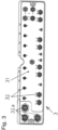
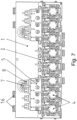
- the block structure has a hydraulic level 1 ( Fig. 1 ), a mounting level 2 ( Fig. 2 ) and an electronics level 3 ( Fig. 3 ). Hydraulic level 1, assembly level 2 and electronic level 3 are Each is manufactured as a separate assembly and is manufactured according to Fig. 8 assembled together as a functionally interconnected common assembly.
- the hydraulic level 1 has a cuboid-shaped base body 11.
- channel structures (not shown in the drawing) specifically designed for the concrete adaptation are designed to guide operating materials.
- a plurality of first recesses 12 are designed in the lower section of the base body 11.
- the recesses 12 are each aligned horizontally and perpendicular to the longitudinal direction of the base body 11 and are arranged vertically one above the other in pairs.
- Each recess 12 has a flow connection (not shown in the drawing) to one of the channel structures designed in the interior on its section directed towards the interior of the base body 11.
- each recess 12 has an open channel as a flow connection to a block valve 4 on its section directed towards the outside of the base body 11.
- Recesses 12 lying one above the other in pairs can be brought into operative connection with a block valve 4.
- actuating elements (not shown in the drawing) for the channel structures in the interior 11 and for the block valves 4 can be arranged.
- the hydraulic level 1 has at least two further recesses 15 in the upper section. These recesses 15 are also each aligned horizontally and arranged perpendicular to the longitudinal direction of the base body 11 and on a common horizontal line. Each recess 15 is designed as a receptacle for a temperature sensor,
- the assembly level 2 has a rectangular base plate 21.
- a plurality of first through-openings 22 are formed in the lower section of the base plate 21.
- the through-openings 22 are each aligned horizontally and perpendicular to the longitudinal direction of the base plate 21 and arranged vertically one above the other in pairs.
- the block valves 4 are fixed in position in the through-openings 22, whereby the number and design of these block valves 4 can be selected depending on the specific filling task.
- the arrangement and geometric shape of the first through-openings 22 is congruent with the first recesses 12 formed in the lower section of the cuboid-shaped base body 11 of the hydraulic level 1.
- a plurality of second through-openings 23 are formed above the first through-openings 22.
- the arrangement and geometric shape of these second through-openings 23 is congruent with the further recesses 13 formed in the cuboid-shaped base body 11 of the hydraulic level 1 above the first recesses 12.
- a plurality of third through-openings 24 are formed in the upper section of the base plate 21. These third through-openings 24 form a hole grid in their entirety.
- This hole grid is designed as a support for at least one assembly 5 ( Fig. 5 ) to accommodate sensors.
- the variable arrangement of sensors that is thus possible also determines the sensor position on hydraulic level 1, so that an optimal assignment for the respective parameter to be recorded by sensors is guaranteed.
- two modules 5 are provided for receiving sensors, which are mounted in through-openings 24 of the base plate 21. Regardless of the specific number, it is proposed that each module 5 for receiving sensors be equipped with a maximum of four separate pressure sensors.
- Circular recesses 25 for receiving sealing elements are formed on the circumference of the first through-openings 22, which are arranged vertically one above the other in pairs, and on the circumference of the second through-openings 23 arranged above them on the base plate 21 of the mounting plane 2.
- the electronics level 3 has a rectangular base plate 31. Recesses and through-openings 32 are formed in the base area of the base plate 31, each of which is aligned horizontally and arranged perpendicular to the longitudinal direction of the base plate. Actuating elements for the channel structures formed in the hydraulic level 1 and the block valves 4 mounted in the hydraulic level 1 by means of the mounting level 2 are assigned to the recesses and through-openings 32.
- the electronic level 3 can be mounted on a separate mounting plate 6, which in turn is attached to the two lateral front sides of the hydraulic level 1.
- a mounting plate 6 is in Fig. 4 shown as a single assembly, whereby the design of a suitable holding plate 6 is not limited to this construction.
- each block valve can be assigned 4 connectors or LEDs to indicate the operating state or functionality.
- the hydraulic level 1 can have connecting elements 16 on its upper and/or lower longitudinal side, with which a first hydraulic level 1 can be joined with further hydraulic levels to form a common larger structural unit.
Landscapes
- Engineering & Computer Science (AREA)
- General Engineering & Computer Science (AREA)
- Mechanical Engineering (AREA)
- Control Of Transmission Device (AREA)
- Filling Or Discharging Of Gas Storage Vessels (AREA)
- Valve Housings (AREA)
- Fluid-Pressure Circuits (AREA)
Applications Claiming Priority (2)
| Application Number | Priority Date | Filing Date | Title |
|---|---|---|---|
| DE102018008848.1A DE102018008848A1 (de) | 2018-11-08 | 2018-11-08 | Vorrichtung zur Befüllung von Behältern mit Betriebsstoffen an Montagelinien der Automobilindustrie |
| PCT/DE2019/000262 WO2020094164A1 (de) | 2018-11-08 | 2019-10-10 | Vorrichtung zur befüllung von behältern mit betriebsstoffen an montagelinien der automobilindustrie |
Publications (2)
| Publication Number | Publication Date |
|---|---|
| EP3877682A1 EP3877682A1 (de) | 2021-09-15 |
| EP3877682B1 true EP3877682B1 (de) | 2024-12-04 |
Family
ID=68617965
Family Applications (1)
| Application Number | Title | Priority Date | Filing Date |
|---|---|---|---|
| EP19805883.6A Active EP3877682B1 (de) | 2018-11-08 | 2019-10-10 | Vorrichtung zur befüllung von behältern mit betriebsstoffen an montagelinien der automobilindustrie |
Country Status (6)
| Country | Link |
|---|---|
| EP (1) | EP3877682B1 (pl) |
| DE (1) | DE102018008848A1 (pl) |
| ES (1) | ES3015130T3 (pl) |
| HU (1) | HUE070350T2 (pl) |
| PL (1) | PL3877682T3 (pl) |
| WO (1) | WO2020094164A1 (pl) |
Families Citing this family (4)
| Publication number | Priority date | Publication date | Assignee | Title |
|---|---|---|---|---|
| DE102020006487A1 (de) * | 2020-10-20 | 2022-04-21 | Dürr Somac GmbH | Schnellwechseleinrichtung für einen Fülladapter |
| DE102022001507A1 (de) | 2022-04-29 | 2023-11-02 | Dürr Somac GmbH | Verbindungshülse für hydraulische und pneumatische Baugruppen |
| DE102022004464A1 (de) * | 2022-11-29 | 2024-05-29 | Dürr Somac GmbH | Baueinheit zur Ausgestaltung einer Schnittstelle für einen Befülladapter zur Befüllung von Fahrzeugen |
| DE102023001333A1 (de) * | 2023-04-04 | 2024-10-10 | Dürr Somac GmbH | Verfahren und Vorrichtung zur Befüllung von Behältern und Kreisläufen von Fahrzeugen mit flüssigen Betriebsstoffen |
Family Cites Families (8)
| Publication number | Priority date | Publication date | Assignee | Title |
|---|---|---|---|---|
| DE4004834C2 (de) * | 1990-02-16 | 1996-06-13 | Festo Kg | Ventilbaugruppe |
| DE19511395A1 (de) | 1995-03-28 | 1996-10-02 | Buerkert Werke Gmbh & Co | Modulares Ventilsystem zum Sammeln und Verteilen von Flüssigkeiten |
| DE10347936B4 (de) * | 2003-10-15 | 2007-09-27 | Bosch Rexroth Pneumatics Gmbh | Ventilanordnung mit einstellbarer Funktion und Verfahren hierfür |
| DE102006020277A1 (de) * | 2006-04-27 | 2007-10-31 | Conti Temic Microelectronic Gmbh | Druckverteiler für ein Kraftfahrzeug, insbesondere für pneumatische Aktoren in Sitzen |
| DE202006015673U1 (de) | 2006-10-12 | 2007-02-22 | Bürkert Werke GmbH & Co. | Modularer Ventilblock |
| US9010579B2 (en) * | 2011-08-23 | 2015-04-21 | Automatic Bar Controls, Inc. | Manifold module for beverage dispensing system |
| DE102015009290A1 (de) * | 2015-07-10 | 2016-01-21 | Daimler Ag | Verfahren zum Befüllen eines Kältemittelkreislaufs eines Kraftwagens |
| CA3023779A1 (en) * | 2016-05-13 | 2017-11-16 | Castrol Limited | Apparatus and method |
-
2018
- 2018-11-08 DE DE102018008848.1A patent/DE102018008848A1/de active Pending
-
2019
- 2019-10-10 PL PL19805883.6T patent/PL3877682T3/pl unknown
- 2019-10-10 EP EP19805883.6A patent/EP3877682B1/de active Active
- 2019-10-10 HU HUE19805883A patent/HUE070350T2/hu unknown
- 2019-10-10 ES ES19805883T patent/ES3015130T3/es active Active
- 2019-10-10 WO PCT/DE2019/000262 patent/WO2020094164A1/de not_active Ceased
Also Published As
| Publication number | Publication date |
|---|---|
| HUE070350T2 (hu) | 2025-05-28 |
| ES3015130T3 (en) | 2025-04-29 |
| EP3877682A1 (de) | 2021-09-15 |
| PL3877682T3 (pl) | 2025-03-24 |
| DE102018008848A1 (de) | 2020-05-14 |
| WO2020094164A1 (de) | 2020-05-14 |
Similar Documents
| Publication | Publication Date | Title |
|---|---|---|
| EP3877682B1 (de) | Vorrichtung zur befüllung von behältern mit betriebsstoffen an montagelinien der automobilindustrie | |
| DE10245815B4 (de) | Druckluftsteuervorrichtung für eine elektronische Luftfederungsanlage für ein Fahrzeug | |
| DE102008048562A1 (de) | Ventilanordnung zur Brems- sowie Zusatzgeräteansteuerung einer pneumatischen Bremsanlage eines Fahrzeuges | |
| DE19746179A1 (de) | Druckluftwartungseinheit | |
| DE102012109206A1 (de) | Ventil-Sensor-Anordnung für Kraftfahrzeugklimaanlagen | |
| EP3296602B1 (de) | Fluidverteilervorrichtung | |
| DE102011100327B3 (de) | Fluidtechnische Baugruppe | |
| EP2707604B1 (de) | Entlüftungsvorrichtung für hydraulische schleifen | |
| WO2018171837A1 (de) | Betätigungsmodul für kupplungen und gangstellersysteme und getriebe mit betätigungsmodul | |
| DE3427589A1 (de) | Ventiltraeger | |
| EP1711717B1 (de) | Druckluftwartungsvorrichtung | |
| WO2008058862A1 (de) | Getriebe- und kupplungssteuerung | |
| DE102011009215B4 (de) | Steuerventileinheit für ein Automatikgetriebe eines Kraftfahrzeugs | |
| DE102018215218A1 (de) | Fluidmodulanordnung | |
| DE10303078A1 (de) | Anordnung zum Messen eines Druckes in einem flüssigen oder gasförmigen Medium | |
| EP1923285B1 (de) | Vorrichtung mit Ventilgehäuse und Druckluftleitung | |
| EP1762364B1 (de) | Vorrichtung zum Filtrieren eines Fluids, insbesondere für kunststoffverarbeitende Anlagen | |
| DE102005028201B4 (de) | Betätigungsaggregat | |
| DE10328422A1 (de) | Positionserfassungsvorrichtung sowie damit ausgestattete fluidtechnische Vorrichtung | |
| EP0581178B1 (de) | Filterdeckeleinrichtung in Modulbauweise | |
| DE102021119147A1 (de) | Ventileinrichtung zur Anordnung in oder an einem pneumatischen Spann- oder Greifmittel und pneumatisches Spann- oder Greifmittel | |
| EP1296123B1 (de) | Messgeräteinstallation an einer Prozessleitung einer Prozessanlage | |
| DE102022004464A1 (de) | Baueinheit zur Ausgestaltung einer Schnittstelle für einen Befülladapter zur Befüllung von Fahrzeugen | |
| EP2063131B1 (de) | Schaltschrank mit interner Ventilanordnung | |
| DE102008062228A1 (de) | Schnellverbindung einer Leitungsanschlussstelle |
Legal Events
| Date | Code | Title | Description |
|---|---|---|---|
| STAA | Information on the status of an ep patent application or granted ep patent |
Free format text: STATUS: UNKNOWN |
|
| STAA | Information on the status of an ep patent application or granted ep patent |
Free format text: STATUS: THE INTERNATIONAL PUBLICATION HAS BEEN MADE |
|
| PUAI | Public reference made under article 153(3) epc to a published international application that has entered the european phase |
Free format text: ORIGINAL CODE: 0009012 |
|
| STAA | Information on the status of an ep patent application or granted ep patent |
Free format text: STATUS: REQUEST FOR EXAMINATION WAS MADE |
|
| 17P | Request for examination filed |
Effective date: 20210528 |
|
| AK | Designated contracting states |
Kind code of ref document: A1 Designated state(s): AL AT BE BG CH CY CZ DE DK EE ES FI FR GB GR HR HU IE IS IT LI LT LU LV MC MK MT NL NO PL PT RO RS SE SI SK SM TR |
|
| DAV | Request for validation of the european patent (deleted) | ||
| DAX | Request for extension of the european patent (deleted) | ||
| P01 | Opt-out of the competence of the unified patent court (upc) registered |
Effective date: 20230606 |
|
| GRAP | Despatch of communication of intention to grant a patent |
Free format text: ORIGINAL CODE: EPIDOSNIGR1 |
|
| STAA | Information on the status of an ep patent application or granted ep patent |
Free format text: STATUS: GRANT OF PATENT IS INTENDED |
|
| INTG | Intention to grant announced |
Effective date: 20240305 |
|
| GRAJ | Information related to disapproval of communication of intention to grant by the applicant or resumption of examination proceedings by the epo deleted |
Free format text: ORIGINAL CODE: EPIDOSDIGR1 |
|
| STAA | Information on the status of an ep patent application or granted ep patent |
Free format text: STATUS: REQUEST FOR EXAMINATION WAS MADE |
|
| GRAS | Grant fee paid |
Free format text: ORIGINAL CODE: EPIDOSNIGR3 |
|
| STAA | Information on the status of an ep patent application or granted ep patent |
Free format text: STATUS: GRANT OF PATENT IS INTENDED |
|
| GRAP | Despatch of communication of intention to grant a patent |
Free format text: ORIGINAL CODE: EPIDOSNIGR1 |
|
| INTC | Intention to grant announced (deleted) | ||
| GRAA | (expected) grant |
Free format text: ORIGINAL CODE: 0009210 |
|
| STAA | Information on the status of an ep patent application or granted ep patent |
Free format text: STATUS: THE PATENT HAS BEEN GRANTED |
|
| INTG | Intention to grant announced |
Effective date: 20241011 |
|
| AK | Designated contracting states |
Kind code of ref document: B1 Designated state(s): AL AT BE BG CH CY CZ DE DK EE ES FI FR GB GR HR HU IE IS IT LI LT LU LV MC MK MT NL NO PL PT RO RS SE SI SK SM TR |
|
| REG | Reference to a national code |
Ref country code: CH Ref legal event code: EP |
|
| REG | Reference to a national code |
Ref country code: DE Ref legal event code: R096 Ref document number: 502019012620 Country of ref document: DE |
|
| REG | Reference to a national code |
Ref country code: IE Ref legal event code: FG4D Free format text: LANGUAGE OF EP DOCUMENT: GERMAN |
|
| REG | Reference to a national code |
Ref country code: LT Ref legal event code: MG9D |
|
| REG | Reference to a national code |
Ref country code: NL Ref legal event code: MP Effective date: 20241204 Ref country code: SK Ref legal event code: T3 Ref document number: E 45919 Country of ref document: SK |
|
| PG25 | Lapsed in a contracting state [announced via postgrant information from national office to epo] |
Ref country code: HR Free format text: LAPSE BECAUSE OF FAILURE TO SUBMIT A TRANSLATION OF THE DESCRIPTION OR TO PAY THE FEE WITHIN THE PRESCRIBED TIME-LIMIT Effective date: 20241204 |
|
| PG25 | Lapsed in a contracting state [announced via postgrant information from national office to epo] |
Ref country code: FI Free format text: LAPSE BECAUSE OF FAILURE TO SUBMIT A TRANSLATION OF THE DESCRIPTION OR TO PAY THE FEE WITHIN THE PRESCRIBED TIME-LIMIT Effective date: 20241204 |
|
| PG25 | Lapsed in a contracting state [announced via postgrant information from national office to epo] |
Ref country code: BG Free format text: LAPSE BECAUSE OF FAILURE TO SUBMIT A TRANSLATION OF THE DESCRIPTION OR TO PAY THE FEE WITHIN THE PRESCRIBED TIME-LIMIT Effective date: 20241204 |
|
| PG25 | Lapsed in a contracting state [announced via postgrant information from national office to epo] |
Ref country code: NO Free format text: LAPSE BECAUSE OF FAILURE TO SUBMIT A TRANSLATION OF THE DESCRIPTION OR TO PAY THE FEE WITHIN THE PRESCRIBED TIME-LIMIT Effective date: 20250304 |
|
| PG25 | Lapsed in a contracting state [announced via postgrant information from national office to epo] |
Ref country code: GR Free format text: LAPSE BECAUSE OF FAILURE TO SUBMIT A TRANSLATION OF THE DESCRIPTION OR TO PAY THE FEE WITHIN THE PRESCRIBED TIME-LIMIT Effective date: 20250305 Ref country code: LV Free format text: LAPSE BECAUSE OF FAILURE TO SUBMIT A TRANSLATION OF THE DESCRIPTION OR TO PAY THE FEE WITHIN THE PRESCRIBED TIME-LIMIT Effective date: 20241204 |
|
| PG25 | Lapsed in a contracting state [announced via postgrant information from national office to epo] |
Ref country code: RS Free format text: LAPSE BECAUSE OF FAILURE TO SUBMIT A TRANSLATION OF THE DESCRIPTION OR TO PAY THE FEE WITHIN THE PRESCRIBED TIME-LIMIT Effective date: 20250304 |
|
| REG | Reference to a national code |
Ref country code: ES Ref legal event code: FG2A Ref document number: 3015130 Country of ref document: ES Kind code of ref document: T3 Effective date: 20250429 |
|
| PG25 | Lapsed in a contracting state [announced via postgrant information from national office to epo] |
Ref country code: NL Free format text: LAPSE BECAUSE OF FAILURE TO SUBMIT A TRANSLATION OF THE DESCRIPTION OR TO PAY THE FEE WITHIN THE PRESCRIBED TIME-LIMIT Effective date: 20241204 |
|
| REG | Reference to a national code |
Ref country code: HU Ref legal event code: AG4A Ref document number: E070350 Country of ref document: HU |
|
| PG25 | Lapsed in a contracting state [announced via postgrant information from national office to epo] |
Ref country code: SM Free format text: LAPSE BECAUSE OF FAILURE TO SUBMIT A TRANSLATION OF THE DESCRIPTION OR TO PAY THE FEE WITHIN THE PRESCRIBED TIME-LIMIT Effective date: 20241204 |
|
| PG25 | Lapsed in a contracting state [announced via postgrant information from national office to epo] |
Ref country code: IS Free format text: LAPSE BECAUSE OF FAILURE TO SUBMIT A TRANSLATION OF THE DESCRIPTION OR TO PAY THE FEE WITHIN THE PRESCRIBED TIME-LIMIT Effective date: 20250404 |
|
| PG25 | Lapsed in a contracting state [announced via postgrant information from national office to epo] |
Ref country code: PT Free format text: LAPSE BECAUSE OF FAILURE TO SUBMIT A TRANSLATION OF THE DESCRIPTION OR TO PAY THE FEE WITHIN THE PRESCRIBED TIME-LIMIT Effective date: 20250404 |
|
| PG25 | Lapsed in a contracting state [announced via postgrant information from national office to epo] |
Ref country code: EE Free format text: LAPSE BECAUSE OF FAILURE TO SUBMIT A TRANSLATION OF THE DESCRIPTION OR TO PAY THE FEE WITHIN THE PRESCRIBED TIME-LIMIT Effective date: 20241204 |
|
| PG25 | Lapsed in a contracting state [announced via postgrant information from national office to epo] |
Ref country code: RO Free format text: LAPSE BECAUSE OF FAILURE TO SUBMIT A TRANSLATION OF THE DESCRIPTION OR TO PAY THE FEE WITHIN THE PRESCRIBED TIME-LIMIT Effective date: 20241204 |
|
| REG | Reference to a national code |
Ref country code: DE Ref legal event code: R097 Ref document number: 502019012620 Country of ref document: DE |
|
| PG25 | Lapsed in a contracting state [announced via postgrant information from national office to epo] |
Ref country code: SE Free format text: LAPSE BECAUSE OF FAILURE TO SUBMIT A TRANSLATION OF THE DESCRIPTION OR TO PAY THE FEE WITHIN THE PRESCRIBED TIME-LIMIT Effective date: 20241204 |
|
| PG25 | Lapsed in a contracting state [announced via postgrant information from national office to epo] |
Ref country code: DK Free format text: LAPSE BECAUSE OF FAILURE TO SUBMIT A TRANSLATION OF THE DESCRIPTION OR TO PAY THE FEE WITHIN THE PRESCRIBED TIME-LIMIT Effective date: 20241204 |
|
| PLBE | No opposition filed within time limit |
Free format text: ORIGINAL CODE: 0009261 |
|
| STAA | Information on the status of an ep patent application or granted ep patent |
Free format text: STATUS: NO OPPOSITION FILED WITHIN TIME LIMIT |
|
| PGFP | Annual fee paid to national office [announced via postgrant information from national office to epo] |
Ref country code: PL Payment date: 20250923 Year of fee payment: 7 |
|
| 26N | No opposition filed |
Effective date: 20250905 |
|
| PGFP | Annual fee paid to national office [announced via postgrant information from national office to epo] |
Ref country code: HU Payment date: 20251027 Year of fee payment: 7 |
|
| PGFP | Annual fee paid to national office [announced via postgrant information from national office to epo] |
Ref country code: DE Payment date: 20251021 Year of fee payment: 7 |
|
| PGFP | Annual fee paid to national office [announced via postgrant information from national office to epo] |
Ref country code: IT Payment date: 20251021 Year of fee payment: 7 |
|
| PGFP | Annual fee paid to national office [announced via postgrant information from national office to epo] |
Ref country code: FR Payment date: 20251030 Year of fee payment: 7 |
|
| PGFP | Annual fee paid to national office [announced via postgrant information from national office to epo] |
Ref country code: CZ Payment date: 20251007 Year of fee payment: 7 |
|
| PGFP | Annual fee paid to national office [announced via postgrant information from national office to epo] |
Ref country code: SK Payment date: 20251008 Year of fee payment: 7 |
|
| PGFP | Annual fee paid to national office [announced via postgrant information from national office to epo] |
Ref country code: ES Payment date: 20251216 Year of fee payment: 7 |