EP3877225B1 - Fussbremsventil einer druckluftbremsanlage - Google Patents
Fussbremsventil einer druckluftbremsanlage Download PDFInfo
- Publication number
- EP3877225B1 EP3877225B1 EP19795467.0A EP19795467A EP3877225B1 EP 3877225 B1 EP3877225 B1 EP 3877225B1 EP 19795467 A EP19795467 A EP 19795467A EP 3877225 B1 EP3877225 B1 EP 3877225B1
- Authority
- EP
- European Patent Office
- Prior art keywords
- wall
- annular collar
- installation plate
- brake valve
- intermediate flange
- Prior art date
- Legal status (The legal status is an assumption and is not a legal conclusion. Google has not performed a legal analysis and makes no representation as to the accuracy of the status listed.)
- Active
Links
Images


Classifications
-
- B—PERFORMING OPERATIONS; TRANSPORTING
- B60—VEHICLES IN GENERAL
- B60T—VEHICLE BRAKE CONTROL SYSTEMS OR PARTS THEREOF; BRAKE CONTROL SYSTEMS OR PARTS THEREOF, IN GENERAL; ARRANGEMENT OF BRAKING ELEMENTS ON VEHICLES IN GENERAL; PORTABLE DEVICES FOR PREVENTING UNWANTED MOVEMENT OF VEHICLES; VEHICLE MODIFICATIONS TO FACILITATE COOLING OF BRAKES
- B60T15/00—Construction arrangement, or operation of valves incorporated in power brake systems and not covered by groups B60T11/00 or B60T13/00
- B60T15/02—Application and release valves
- B60T15/04—Driver's valves
- B60T15/043—Driver's valves controlling service pressure brakes
-
- B—PERFORMING OPERATIONS; TRANSPORTING
- B60—VEHICLES IN GENERAL
- B60T—VEHICLE BRAKE CONTROL SYSTEMS OR PARTS THEREOF; BRAKE CONTROL SYSTEMS OR PARTS THEREOF, IN GENERAL; ARRANGEMENT OF BRAKING ELEMENTS ON VEHICLES IN GENERAL; PORTABLE DEVICES FOR PREVENTING UNWANTED MOVEMENT OF VEHICLES; VEHICLE MODIFICATIONS TO FACILITATE COOLING OF BRAKES
- B60T7/00—Brake-action initiating means
- B60T7/02—Brake-action initiating means for personal initiation
- B60T7/04—Brake-action initiating means for personal initiation foot actuated
- B60T7/06—Disposition of pedal
Definitions
- the invention relates to a foot brake valve of a compressed air brake system in a motor vehicle, with a mounting plate on which a brake pedal is pivotably mounted and on which a housing of an electrical control unit and/or a pneumatic control unit is attached, with an annular collar protruding from the top of the mounting plate spring-loaded plunger piston located in adjusting contact with the brake pedal is guided so that it can move axially.
- a foot brake valve of a compressed air brake system has the function of adjusting the brake pressure in the usually two brake circuits of a motor vehicle and possibly a trailer vehicle as a function of the setting position of the brake pedal to be actuated by a driver.
- control pistons of the pneumatic control unit are in adjustment connection via an axially movable guided ram with the spring-loaded ram piston, which is in direct adjustment contact with the brake valve.
- the pneumatic control unit housing has two input ports and two output ports. When installed, a supply pressure line protected by a multi-circuit protection valve is connected to the input connections. A brake pressure line of the respectively associated brake circuit is connected to each of the output connections.
- the input ports and the output ports of the pneumatic control unit are mostly located on opposite sides of the housing.
- designs of foot brake valves are also known in which the input connections and the output connections of the pneumatic control unit are arranged next to one another on the same side of the housing.
- An electrical control unit can also be arranged between a mounting plate of the foot brake valve and the pneumatic control unit, by means of which the brake lights of the motor vehicle and, if applicable, a trailer vehicle can be switched on and off and/or the braking force of a retarder can be metered, depending on the position of the brake pedal.
- an electrical A connector socket is provided for the connection cable and is usually arranged on a protruding base on one side of the housing.
- a foot brake valve of a compressed air brake system in which an electrical control unit for gradually controlling the braking force of a retarder is arranged between the mounting plate and the pneumatic control unit.
- a foot brake valve of a compressed air brake system in which an electrical control unit for switching the brake lights of the motor vehicle and optionally a trailer vehicle on and off is arranged between the mounting plate and the pneumatic control unit.
- the housings of the pneumatic control unit and the electric control unit in the foot brake valves from WABCO GmbH, Hanover are each connected to one another and to the mounting plate via a flange screw connection. Since both the connecting flanges and their hole pattern are square and symmetrical to the vertical central axis of the respective foot brake valve, the pneumatic control unit and the electrical control unit can also be rotated independently of one another by 90°, 180° or 270° with respect to the vertical central axis compared to a standard arrangement on the mounting plate to be attached. This allows the connections of the pneumatic control unit and the socket of the electrical control unit to be oriented to a limited extent in the way that is most favorable for the installation of the foot brake valve in a particular motor vehicle.
- the present invention was based on the object of presenting a foot brake valve of a compressed air brake system of the type mentioned at the outset, in which the housing of an electrical control unit and/or a pneumatic Control unit stepless or at least more finely graded than can be rotated in 90° steps around the vertical central axis and attached to the mounting plate.
- the invention accordingly relates to a foot brake valve of a compressed air brake system in a motor vehicle, which has a mounting plate on which a brake pedal is pivotably mounted and on which a housing for an electrical control unit and/or a pneumatic control unit is attached, with a housing protruding from the mounting plate at the top
- a spring-loaded collar which is in adjusting contact with the brake pedal, is guided in an axially movable manner.
- the housing of the control unit arranged directly under the mounting plate has an intermediate flange which is screwed to the main part of the housing and has the annular collar, and that the intermediate flange with the annular collar can be guided in a passage opening of the mounting plate so that it can rotate coaxially about a vertical central axis and can be non-positively connected to the mounting plate by means of a detachable clamp connection.
- the housing of the pneumatic control unit and optionally the electrical control unit be attached to the mounting plate rotated about the vertical central axis in such a way that the line connections of the pneumatic control unit for connecting compressed air lines and, if necessary, the socket of the electrical control unit for connecting a connecting cable in the respective motor vehicle are optimally aligned.
- the clamping connection is formed by an outer annular groove in the annular collar of the intermediate flange and two clamping plates arranged diagonally opposite one another on the annular collar on the mounting plate and engaging in the annular groove, and that the clamping plates are screwed to the mounting plate are each angled radially inwards upwards in cross-section and, in the assembled state, rest with an arc-shaped inner end wall on the groove base of the annular groove and with their axially outer inner edge on the upper side wall of the annular groove.
- the intermediate flange is positively and non-positively attached to the mounting plate.
- the inner end wall of the clamping plates and the bottom of the annular groove of the annular collar, on which the clamping plates and the annular collar of the intermediate flange are clamped radially against one another, can each be smooth, which means that when the screw connection of the clamping plates is loosened, the circumferential alignment of the housing of the control units can be adjusted continuously the mounting plate is possible.
- the inner end wall of the clamping plates and the groove base of the annular groove of the annular collar can also be toothed on the circumferential side, which increases the security against twisting of the components and, when the screw connection of the clamping plates is loosened, a graduated adjustment of the circumferential alignment of the housing of the control units relative to each other in accordance with the toothing pitch the mounting plate is possible.
- the inner The end wall of the clamping plates and the bottom of the annular groove of the annular collar are each preferably provided with circumferential serrations.
- the clamping connection is formed by a clamping screw connection, which has the following: an annular collar on the upper side of the mounting plate with a cylindrical inner wall, a clamping ring with a cylindrical outer wall and a conical one narrowing axially downwards inner wall and a conical outer wall on the annular collar of the intermediate flange as well as a union nut with an internal thread, with the clamping ring being arranged between the inner wall of the annular collar of the mounting plate and the outer wall of the annular collar of the intermediate flange in the mounted state, and with the screw connection of the union nut with the Annular collar of the mounting plate by means of the clamping ring causes radial tensioning of the two annular collars.
- the intermediate flange is positively and non-positively attached to the mounting plate.
- cylindrical inner wall of the annular collar of the mounting plate, the conical inner wall and the cylindrical outer wall of the clamping ring and the conical outer wall of the annular collar of the intermediate flange are each smooth.
- the cylindrical inner wall of the annular collar of the mounting plate, the conical inner wall and the cylindrical outer wall of the clamping ring and the conical outer wall of the annular collar of the intermediate flange are each toothed on the peripheral side. This increases the security against twisting of the components, and when the screw connection of the union nut is loosened, a graduated adjustment of the circumferential alignment of the housing of the control units with respect to the mounting plate is possible in accordance with the toothing pitch.
- the cylindrical inner wall of the annular collar of the mounting plate, the conical inner wall and the cylindrical outer wall of the clamping ring and the conical outer wall of the annular collar of the intermediate flange are each provided with circumferential serrations .
- the clamping connection is formed by a clamping screw connection, which has the following: An annular collar on the upper side of the mounting plate with an external thread and with a conical inner wall that narrows axially downwards, a clamping ring with a conical , axially downward narrowing outer wall and a cylindrical inner wall, a cylindrical outer wall on the annular collar of the intermediate flange and a union nut with an internal thread, and with an external thread on the annular collar of the intermediate flange and an internal thread on the inner wall of the clamping ring, with the internal thread of the clamping ring in the mounted state is screwed to the external thread of the intermediate flange, and by screwing the union nut to the collar of the mounting plate via the clamping ring, a radial tension of the two collars is effected.
- the inner wall of the annular collar on the upper side of the mounting plate and the outer wall of the clamping ring are each smooth.
- the clamping ring at least in the last-mentioned embodiment, is designed to be axially slotted or consists of several ring segments. This makes it easier to press the clamping ring in coaxially into the clamping seat.
- the known foot brake valve 2 of a compressed air brake system illustrated has a mounting plate 4 with an annular collar 6 projecting upwards and two tabs 8, 8' arranged parallel to one another on the upper side of the mounting plate 4.
- a bearing pin 12 on which a brake pedal 14 is pivotably mounted is inserted in each bearing bore 10 of the brackets 8, 8'.
- the housing 18 of an electrical control unit 16 and the housing 28 of a pneumatic control unit 26 are arranged on the underside of the mounting plate 4 and are connected to one another and to the mounting plate 4 via a respective flange screw connection 24 , 30 .
- the control elements of the two control units 16, 26, such as electrical switches and pneumatic valves, are in control connection with an elongate plunger 34, which is axially movable coaxially with a vertical center axis 32 of the housing 18, 28.
- the tappet 34 engages in a central bore of a tappet piston 36 which, loaded by a compression spring 38 designed as a helical spring, is guided in an axially movable manner in the annular collar 6 of the mounting plate 4 and is directly connected to the brake pedal 14.
- a socket 22 mounted on a base 20 is arranged on the back of the housing 18, to which an electrical connecting cable leading to a control unit or directly to the retarder can be connected.
- the output ports p21, p22 of two brake circuits of the motor vehicle are each blocked from a venting output p3 and connected to an associated input port p11, p12 by the actuation of the brake pedal and the axial displacement of the tappet 34 caused thereby downwards, whereby the at the brake pressure present at the output connections p21, p22 is continuously increased.
- the input connections p11, p12, to which a supply pressure line protected by a multi-circuit protection valve is connected when installed, and the output connections p21, p22, to which a brake pressure line of the assigned brake circuit is connected when installed are next to each other on the rear of the housing 28 arranged.
- the connecting flanges of the flange screw connections 24, 30 and their hole pattern are square and symmetrical to the vertical central axis 32 of the foot brake valve 2, so that the pneumatic control unit 26 and the electrical control unit 16 can also be rotated independently of one another with respect to the vertical central axis 32 by 90°, 180° or rotated 270° to the standard arrangement shown on the mounting plate 4. Since this only allows a limited alignment of the input and output connections p11, p12, p21, p22 of the pneumatic control unit 26 and the socket 22 of the electrical control unit 16 to the conditions in a specific motor vehicle, the foot brake valve according to the invention should be stepless or at least finely graduated Allow alignment of the housing 18, 28 of the two control units 16, 26 with respect to the central axis 32.
- the housing 18' of the electrical control unit 16 has an intermediate flange 48 which is screwed to the main part of the housing 18' by means of Allen screws and has an annular collar 50 in which the plunger piston 36 can move axially is led.
- a plain bearing bushing 58 and a sealing ring 60 are inserted into the annular collar 50 of the intermediate flange 48 for low-friction and sealed guidance of the plunger piston 36 .
- the intermediate flange 48 is guided with the annular collar 50 so as to be rotatable about the vertical central axis 32 in a passage opening 40 in the mounting plate 4' and can be connected non-positively to the mounting plate 4' by means of a detachable clamp connection 62.
- the clamping connection 62 is formed by a radially outer annular groove 52 in the annular collar 50 of the intermediate flange 48 and two clamping plates 64, 64' which are arranged diagonally opposite one another on the annular collar 50 on the mounting plate 4' and engage in the annular groove 52.
- the two clamping plates 64, 64' are screwed to the mounting plate 4' and are each angled radially inwards in an axial direction upwards.
- the clamping plates 64, 64' each rest with an arcuate inner end wall 66, 66' of the same on the groove bottom 54 of the annular groove 52 and with their axially outer inner edge 68 on the upper side wall 56 of the annular groove 52, whereby the intermediate flange 48 form - And is non-positively attached to the mounting plate 4 '.
- the inner end wall 66 of the clamping plates 64, 64' and the groove bottom 54 of the annular groove 52 of the annular collar 50 can each optionally be smooth or, in particular by means of serrations, toothed on the peripheral side.
- FIG. 1 and 1a are the housings 18', 28 of the control units 16, 26, based on a standard setting in which the pneumatic connections p11, p12, p21, p22 and the socket 22 (in the forward direction of travel) are aligned to the rear, with respect to the vertical center axis 32 rotated by 45 ° counterclockwise, for example, attached to the mounting plate 4 '.
- the housing 18" of the electrical control unit 16 has an intermediate flange 70, which is screwed to the main part of the housing 18".
- the intermediate flange 70 has an annular collar 72, in which the plunger piston 36.
- a plain bearing bushing 58 and a sealing ring 60 are inserted into the annular collar 72 of the intermediate flange 70.
- the intermediate flange 70 can be rotated with the annular collar 72 about the vertical center axis 32 in a passage opening 40' of the Mounting plate 4" out and by means of a detachable clamp connection 76 non-positively connected to the mounting plate 4".
- the clamping connection 76 is formed by a clamping screw connection 78, which has an annular collar 42 on the upper side of the mounting plate 4" with a cylindrical external thread 44 and a cylindrical inner wall 46, as well as a clamping ring 80 with a conical inner wall 84 that narrows axially downwards and having a cylindrical outer wall 82, and a conical outer wall 74 on the annular collar 72 of the intermediate flange 70 and a union nut 86 with an internal thread 88.
- a clamping screw connection 78 which has an annular collar 42 on the upper side of the mounting plate 4" with a cylindrical external thread 44 and a cylindrical inner wall 46, as well as a clamping ring 80 with a conical inner wall 84 that narrows axially downwards and having a cylindrical outer wall 82, and a conical outer wall 74 on the annular collar 72 of the intermediate flange 70 and a union nut 86 with an internal thread 88.
- the union nut 86 acts on an axial elevation on the upper side of the annular collar 72 of the intermediate flange 70
- the clamping ring 80 is arranged between the inner wall 46 of the annular collar 42 of the mounting plate 4" and the outer wall 74 of the annular collar 72 of the intermediate flange 70.
- the cylindrical inner wall 46 of the annular collar 42 of the mounting plate 4", the cylindrical outer wall 82 and the conical inner wall 84 of the clamping ring 80 as well as the conical outer wall 74 of the annular collar 72 of the intermediate flange 70 can each optionally be smooth or, in particular by means of serrations, toothed on the peripheral side
- a stepless adjustment or a graduated adjustment corresponding to the toothing pitch of the circumferential alignment of the housings 18", 28 of the control units 16, 26 with respect to the mounting plate 4" is possible
- Figures 2 and 2a the housings 18", 28 of the control units 16, 26 are, starting from a standard setting in which the pneumatic connections p11, p12, p21, p22 and the socket 22 are aligned to the rear in the forward direction of travel, with respect to the vertical center axis 32, for example, by 45 ° rotated anti-clockwise and attached to the 4" mounting plate.
- FIG. 2b shows a third embodiment of a foot brake valve 2"' having the features of the invention in a partial longitudinal section.
- the clamp connection 77 is also formed by a clamp screw connection 79.
- the clamp screw connection 79 has an annular collar 42 on the upper side of the mounting plate 4". , on which an external thread 44 and a conical inner wall 46 that narrows axially downward is formed.
- the clamp fitting 79 also includes a clamp ring 81 with a conical outer wall 82 that narrows axially downwards and a cylindrical inner wall 84.
- the clamp fitting 79 also has a cylindrical outer wall 74 on the annular collar 72 of the intermediate flange 70 and a union nut 86 with a Internal thread 88.
- the compression fitting 79 also includes an external thread 90 on the annular collar 72 of the intermediate flange 70 and an internal thread 92 on the cylindrical inner wall 84 of the clamping ring 81.
- the union nut 86 was screwed onto the annular collar 42 and can be seen to act on the upper end of the clamping ring 81 as well as on a section of the annular collar 72 of the intermediate flange 70 near the union nut.
- the radial inner wall 46 of the annular collar 42 on the upper side of the mounting plate 4" and the radial outer wall 82 of the clamping ring 80 can each be smooth.
- the clamping ring 81 can be designed with an axial slot or to consist of a plurality of ring segments.
Landscapes
- Engineering & Computer Science (AREA)
- Transportation (AREA)
- Mechanical Engineering (AREA)
- Braking Systems And Boosters (AREA)
Description
- Die Erfindung betrifft ein Fußbremsventil einer Druckluftbremsanlage in einem Motorfahrzeug, mit einer Montageplatte, auf der ein Bremspedal schwenkbar gelagert ist, und an der ein Gehäuse einer elektrischen Steuereinheit und/oder einer pneumatischen Steuereinheit befestigt ist, wobei in einem oben aus der Montageplatte herausragenden Ringbund ein federbelasteter, mit dem Bremspedal in Stellkontakt befindlicher Stößelkolben axialbeweglich geführt ist.
- Ein Fußbremsventil einer Druckluftbremsanlage hat die Funktion, den Bremsdruck in den üblicherweise zwei Bremskreisen eines Motorfahrzeugs und gegebenenfalls eines Anhängefahrzeugs in Abhängigkeit von der Stellposition des von einem Fahrer zu betätigenden Bremspedals einzustellen. Hierzu stehen Steuerkolben der pneumatischen Steuereinheit über einen axialbeweglich geführten Stößel mit dem federbelasteten Stößelkolben in Stellverbindung, der unmittelbar in Stellkontakt mit dem Bremsventil ist. Das Gehäuse der pneumatischen Steuereinheit weist zwei Eingangsanschlüsse und zwei Ausgangsanschlüsse auf. Im eingebauten Zustand ist an die Eingangsanschlüsse jeweils eine über ein Mehrkreisschutzventil abgesicherte Vorratsdruckleitung angeschlossen. An die Ausgangsanschlüsse ist jeweils eine Bremsdruckleitung des jeweils zugeordneten Bremskreises angeschlossen. Die Eingangsanschlüsse und die Ausgangsanschlüsse der pneumatischen Steuereinheit sind zumeist an entgegengesetzten Seiten des Gehäuses angeordnet. Es sind jedoch auch Ausführungen von Fußbremsventilen bekannt, bei denen die Eingangsanschlüsse und die Ausgangsanschlüsse der pneumatischen Steuereinheit an derselben Seite des Gehäuses nebeneinander angeordnet sind.
- Zwischen einer Montageplatte des Fußbremsventils und der pneumatischen Steuereinheit kann zusätzlich eine elektrische Steuereinheit angeordnet sein, mittels der in Abhängigkeit von der Stellposition des Bremspedals die Bremslichter des Motorfahrzeugs und gegebenenfalls eines Anhängefahrzeugs ein- und ausgeschaltet und/oder die Bremskraft eines Retarders dosiert werden kann. Zum Anschluss eines elektrischen Verbindungskabels ist eine Steckerbuchse vorgesehen, die üblicherweise an einem hervorstehenden Sockel an einer Seite des Gehäuses angeordnet ist.
- Aus der
DE 26 19 775 C2 ist ein Fußbremsventil einer Druckluftbremsanlage bekannt, bei dem zwischen der Montageplatte und der pneumatischen Steuereinheit eine elektrische Steuereinheit zur stufenweisen Steuerung der Bremskraft eines Retarders angeordnet ist. - In der
DE 10 2013 015 973 A1 ist dagegen ein Fußbremsventil einer Druckluftbremsanlage beschrieben, bei dem zwischen der Montageplatte und der pneumatischen Steuereinheit eine elektrische Steuereinheit zum Ein- und Ausschalten der Bremslichter des Motorfahrzeugs und gegebenenfalls eines Anhängerfahrzeugs angeordnet ist. - Der Aufbau und die Funktionsweise verschiedener Ausführungen von Fußbremsventilen mit und ohne elektrischer Steuereinheit können der Druckschrift
815 020 003 3 "Systeme und Komponenten in Nutzfahrzeugen" (Ausgabe 2) der WABCO GmbH, Hannover unter Kapitel 1 "Motorwagen-Bremsgeräte", Abschnitt "Motorwagen-Bremsventile" (siehe Seiten 27 bis 32) entnommen werden, die im Internet unter http://www.wabco.info/8150200033 als PDF-Datei abrufbar ist. - Wie den genannten Druckschriften zu entnehmen ist, sind bei den Fußbremsventilen der WABCO GmbH, Hannover die Gehäuse der pneumatischen Steuereinheit und der elektrischen Steuereinheit jeweils über eine Flanschverschraubung miteinander sowie mit der Montageplatte verbunden. Da sowohl die Verbindungsflansche als auch deren Lochbild quadratisch und symmetrisch zur vertikalen Mittelachse des jeweiligen Fußbremsventils ausgeführt sind, können die pneumatische Steuereinheit und die elektrische Steuereinheit unabhängig voneinander bezüglich der vertikalen Mittelachse auch um 90°, 180° oder 270° verdreht zu einer Standardanordnung an der Montageplatte befestigt werden. Hierdurch können die Anschlüsse der pneumatischen Steuereinheit und die Steckerbuchse der elektrischen Steuereinheit in begrenztem Umfang so ausgerichtet werden, wie es für den Einbau des Fußbremsventils in einem bestimmten Motorfahrzeug am günstigsten ist.
- Da diese Verstellmöglichkeit der Gehäuse in 90°-Schritten aber bei einigen Anwendungsfällen unzureichend sein kann, lag der vorliegenden Erfindung die Aufgabe zugrunde, ein Fußbremsventil einer Druckluft-Bremsanlage der eingangs genannten Bauart vorzustellen, bei dem das Gehäuse einer elektrischen Steuereinheit und/oder einer pneumatischen Steuereinheit stufenlos oder zumindest feiner abgestuft als in 90°-Schritten um die vertikale Mittelachse gedreht an der Montageplatte befestigt werden kann.
- Diese Aufgabe ist durch ein Fußbremsventil mit den Merkmalen des Anspruchs 1 gelöst. Vorteilhafte Weiterbildungen sind in den abhängigen Ansprüchen definiert.
- Die Erfindung betrifft demnach ein Fußbremsventil einer Druckluftbremsanlage in einem Motorfahrzeug, die eine Montageplatte aufweist, auf der ein Bremspedal schwenkbar gelagert ist, und an der ein Gehäuse einer elektrischen Steuereinheit und/oder einer pneumatischen Steuereinheit befestigt ist, wobei in einem oben aus der Montageplatte herausragenden Ringbund ein federbelasteter, mit dem Bremspedal in Stellkontakt befindlicher Stößelkolben axialbeweglich geführt ist.
- Um das Gehäuse der pneumatischen Steuereinheit und gegebenenfalls einer elektrischen Steuereinheit stufenlos oder zumindest feiner als in 90°-Schritten um die vertikale Mittelachse des Fußbremsventils verdreht an der Montageplatte befestigen zu können, ist vorgesehen, dass das Gehäuse der unmittelbar unter der Montageplatte angeordneten Steuereinheit einen Zwischenflansch aufweist, der mit dem Hauptteil des Gehäuses verschraubt ist sowie den Ringbund aufweist, und dass der Zwischenflansch mit dem Ringbund um eine vertikale Mittelachse koaxial drehbar in einer Durchtrittsöffnung der Montageplatte geführt sowie mittels einer lösbaren Klemmverbindung kraftschlüssig mit der Montageplatte verbindbar ist.
- Durch die Erweiterung des Fußbremsventils um den Zwischenflansch und die Klemmverbindung ist somit mit geringem Mehraufwand die Möglichkeit geschaffen, das Gehäuse der pneumatischen Steuereinheit und gegebenenfalls der elektrischen Steuereinheit derart um die vertikale Mittelachse gedreht an der Montageplatte zu befestigen, dass die Leitungsanschlüsse der pneumatischen Steuereinheit für den Anschluss von Druckluftleitungen und gegebenenfalls die Steckerbuchse der elektrischen Steuereinheit für den Anschluss eines Verbindungskabels in dem jeweiligen Motorfahrzeug optimal ausgerichtet sind.
- Gemäß einer ersten Ausführungsvariante des erfindungsgemäßen Fußbremsventils ist vorgesehen, dass die Klemmverbindung durch eine äußere Ringnut in dem Ringbund des Zwischenflansches sowie zwei an dem Ringbund diagonal gegenüberliegend auf der Montageplatte angeordnete, in die Ringnut eingreifende Klemmbleche gebildet ist, und dass die Klemmbleche mit der Montageplatte verschraubt sind, jeweils im Querschnitt radial innen nach oben abgewinkelt sind und im montierten Zustand mit einer kreisbogenförmigen inneren Stirnwand an dem Nutboden der Ringnut sowie mit ihrem axial äußeren Innenrand an der oberen Seitenwand der Ringnut anliegen. Hierdurch ist der Zwischenflansch form- und kraftschlüssig an der Montageplatte befestigt.
- Die innere Stirnwand der Klemmbleche und der Nutboden der Ringnut des Ringbundes, an denen die Klemmbleche und der Ringbund des Zwischenflansches radial gegeneinander verspannt sind, können jeweils glatt ausgeführt sein, wodurch bei gelöster Verschraubung der Klemmbleche eine stufenlose Einstellung der umfangsseitigen Ausrichtung der Gehäuse der Steuereinheiten gegenüber der Montageplatte möglich ist.
- Alternativ dazu können die innere Stirnwand der Klemmbleche und der Nutboden der Ringnut des Ringbundes jedoch auch jeweils umfangsseitig verzahnt ausgeführt sein, wodurch eine erhöhte Verdrehsicherheit der Bauteile erzielt und bei gelöster Verschraubung der Klemmbleche eine entsprechend der Verzahnungsteilung abgestufte Einstellung der umfangsseitigen Ausrichtung der Gehäuse der Steuereinheiten gegenüber der Montageplatte möglich ist.
- Um eine möglichst feinstufige Einstellung der umfangsseitigen Ausrichtung der Gehäuse der Steuereinheiten gegenüber der Montageplatte zu ermöglichen, sind die innere Stirnwand der Klemmbleche und der Nutboden der Ringnut des Ringbundes jeweils bevorzugt mit einer umfangsseitigen Kerbverzahnung versehen.
- Gemäß einer zweiten Ausführungsvariante des erfindungsgemäßen Fußbremsventils ist vorgesehen, dass die Klemmverbindung durch eine Klemmverschraubung gebildet ist, welche folgendes aufweist: einen Ringbund an der Oberseite der Montageplatte mit einer zylindrischen Innenwand, einen Klemmring mit einer zylindrischen Außenwand und einer kegelförmigen, sich nach axial unten verengenden Innenwand, und eine kegelförmige Außenwand an dem Ringbund des Zwischenflansches sowie eine Überwurfmutter mit einem Innengewinde, wobei der Klemmring im montierten Zustand zwischen der Innenwand des Ringbundes der Montageplatte und der Außenwand des Ringbundes des Zwischenflansches angeordnet ist, und wobei durch die Verschraubung der Überwurfmutter mit dem Ringbund der Montageplatte mittels des Klemmrings eine radiale Verspannung der beiden Ringbunde bewirkt. Hierdurch ist der Zwischenflansch form- und kraftschlüssig an der Montageplatte befestigt.
- Weiter kann vorgesehen sein, dass die zylindrische Innenwand des Ringbundes der Montageplatte, die kegelförmige Innenwand und die zylindrische Außenwand des Klemmrings sowie die kegelförmige Außenwand des Ringbundes des Zwischenflansches jeweils glatt ausgebildet sind. Hierdurch ist bei gelöster Verschraubung der Überwurfmutter eine stufenlose Einstellung der umfangsseitigen Ausrichtung der Gehäuse der Steuereinheiten gegenüber der Montageplatte möglich.
- Alternativ dazu kann vorgesehen sein, dass die zylindrische Innenwand des Ringbundes der Montageplatte, die kegelförmige Innenwand und die zylindrische Außenwand des Klemmrings sowie die kegelförmige Außenwand des Ringbundes des Zwischenflansches jeweils umfangsseitig verzahnt ausgebildet sind. Hierdurch ist eine erhöhte Verdrehsicherheit der Bauteile erzielt, und bei gelöster Verschraubung der Überwurfmutter ist eine entsprechend der Verzahnungsteilung abgestufte Einstellung der umfangsseitigen Ausrichtung der Gehäuse der Steuereinheiten gegenüber der Montageplatte möglich.
- Um eine möglichst feinstufige Einstellung der umfangsseitigen Ausrichtung der Gehäuse der Steuereinheiten gegenüber der Montageplatte zu ermöglichen, sind die zylindrische Innenwand des Ringbundes der Montageplatte, die kegelförmige Innenwand und die zylindrische Außenwand des Klemmrings sowie die kegelförmige Außenwand des Ringbundes des Zwischenflansches jeweils mit einer umfangsseitigen Kerbverzahnung versehen.
- Gemäß einer anderen Ausführungsform des erfindungsgemäßen Fußbremsventils ist vorgesehen, dass die Klemmverbindung durch eine Klemmverschraubung gebildet ist, welche folgendes aufweist: Einen Ringbund an der Oberseite der Montageplatte mit einem Außengewinde und mit einer kegelförmigen, sich nach axial unten verengenden Innenwand, einen Klemmring mit einer kegelförmigen, sich nach axial unten verengenden Außenwand und einer zylindrischen Innenwand, eine zylindrische Außenwand an dem Ringbund des Zwischenflansches und eine Überwurfmutter mit einem Innengewinde, sowie mit einem Außengewinde am Ringbund des Zwischenflansches und ein Innengewinde an der Innenwand des Klemmrings, wobei dass Innengewinde des Klemmrings im montierten Zustand mit dem Außengewinde des Zwischenflansches verschraubt ist, und wobei durch die Verschraubung der Überwurfmutter mit dem Ringbund der Montageplatte über den Klemmring eine radiale Verspannung der beiden Ringbunde bewirkt wird.
- Hierbei kann vorgesehen sein, dass die Innenwand des Ringbundes an der Oberseite der Montageplatte sowie die Außenwand des Klemmrings jeweils glatt ausgebildet sind.
- Zudem wird es als vorteilhaft erachtet, wenn der Klemmring zumindest der zuletzt genannten Ausführungsform axial geschlitzt ausgebildet ist oder aus mehreren Ringsegmenten besteht. Hierdurch wird das koaxial Hineindrücken des Klemmrings in den Klemmsitz erleichtert.
- Zur weiteren Verdeutlichung der Erfindung ist der Beschreibung eine Zeichnung mit zwei Ausführungsbeispielen beigefügt. In dieser zeigt
-
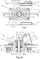
Fig. 1 eine erste Ausführungsform eines erfindungsgemäßen Fußbremsventils einer Druckluftbremsanlage in einer ausschnittsweisen Draufsicht, -
Fig. 1a das Fußbremsventil gemäßFig. 1 in einem ausschnittsweisen Längsschnitt, -
Fig. 2 eine zweite Ausführungsform eines erfindungsgemäßen Fußbremsventils einer Druckluftbremsanlage in einer ausschnittsweisen Draufsicht, -
Fig. 2a das Fußbremsventil gemäßFig. 2 in einem ausschnittsweisen Längsschnitt, -
Fig. 2b eine dritte Ausführungsform eines erfindungsgemäßen Fußbremsventils in einem ausschnittsweisen Längsschnitt, -
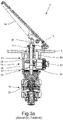
Fig. 3 ein bekanntes Fußbremsventil einer Druckluftbremsanlage in einer perspektivischen Ansicht, und -
Fig. 3a das Fußbremsventil gemäßFig. 3 in einem Längsschnitt. - Ein in einer perspektivischen Ansicht gemäß
Fig. 3 und in einem Längsschnitt gemäßFig. 3a abgebildetes bekanntes Fußbremsventil 2 einer Druckluftbremsanlage weist eine Montageplatte 4 mit einem nach oben herausragenden Ringbund 6 und zwei auf der Oberseite der Montageplatte 4 parallel zueinander angeordnete Laschen 8, 8' auf. In jeweils einer Lagerbohrung 10 der Laschen 8, 8' ist ein Lagerbolzen 12 eingesetzt, auf dem ein Bremspedal 14 schwenkbar gelagert ist. Auf der Unterseite der Montageplatte 4 sind das Gehäuse 18 einer elektrischen Steuereinheit 16 und das Gehäuse 28 einer pneumatischen Steuereinheit 26 angeordnet, die über jeweils eine Flanschverschraubung 24, 30 miteinander sowie mit der Montageplatte 4 verbunden sind. Die Steuerelemente der beiden Steuereinheiten 16, 26, wie elektrische Schalter und pneumatische Ventile, stehen mit einem langgestreckten Stößel 34 in Stellverbindung, der axialbeweglich koaxial zu einer vertikalen Mittelachse 32 der Gehäuse 18, 28 geführt ist. An seinem oberen Ende greift der Stößel 34 in eine Zentralbohrung eines Stößelkolbens 36 ein, der belastet von einer als Schraubenfeder ausgebildeten Druckfeder 38 axialbeweglich in dem Ringbund 6 der Montageplatte 4 geführt ist sowie unmittelbar mit dem Bremspedal 14 in Stellverbindung ist. - Durch eine Betätigung des Bremspedals 14 werden der Stößelkolben 36 und der Stößel 34 gegen die Rückstellkraft der Schraubenfeder 38 nach unten gedrückt, wodurch in der elektrischen Steuereinheit 16 nacheinander elektrische Kontakte geschlossen werden, durch welche die Bremskraft eines in dem betreffenden Motorfahrzeug eingebauten Retarders stufenweise erhöht wird. Zur Übertragung der elektrischen Schaltsignale ist (in Vorwärts-Fahrtrichtung gesehen) auf der Rückseite des Gehäuses 18 eine auf einem Sockel 20 montierte Steckerbuchse 22 angeordnet, an die ein zu einem Steuergerät oder unmittelbar zu dem Retarder führendes elektrisches Verbindungskabel anschließbar ist.
- In der pneumatischen Steuereinheit 26 werden durch die Betätigung des Bremspedals und die dadurch bewirkte Axialverschiebung des Stößels 34 nach unten die Ausgangsanschlüsse p21, p22 von zwei Bremskreisen des Motorfahrzeugs jeweils gegenüber einem Entlüftungsausgang p3 abgesperrt und mit einem zugeordneten Eingangsanschluss p11, p12 verbunden, wodurch der an den Ausgangsanschlüssen p21, p22 anliegende Bremsdruck kontinuierlich erhöht wird. Vorliegend sind die Eingangsanschlüsse p11, p12, an die im eingebauten Zustand jeweils eine über ein Mehrkreisschutzventil abgesicherte Vorratsdruckleitung angeschlossen ist, und die Ausgangsanschlüsse p21, p22, an die im eingebauten Zustand jeweils eine Bremsdruckleitung des zugeordneten Bremskreises angeschlossen ist, nebeneinander auf der Rückseite des Gehäuses 28 angeordnet.
- Die Verbindungsflansche der Flanschverschraubungen 24, 30 als auch deren Lochbild sind quadratisch und symmetrisch zu der vertikalen Mittelachse 32 des Fußbremsventils 2 ausgeführt, so dass die pneumatische Steuereinheit 26 und die elektrische Steuereinheit 16 unabhängig voneinander bezüglich der vertikalen Mittelachse 32 auch um 90°, 180° oder 270° gedreht zu der abgebildeten Standardanordnung an der Montageplatte 4 befestigt werden können. Da hierdurch nur eine eingeschränkte Ausrichtung der Ein- und Ausgangsanschlüsse p11, p12, p21, p22 der pneumatischen Steuereinheit 26 und der Steckerbuchse 22 der elektrischen Steuereinheit 16 an die Gegebenheiten in einem bestimmten Motorfahrzeug möglich ist, soll das erfindungsgemäße Fußbremsventil eine stufenlose oder zumindest feiner abgestufte Ausrichtung der Gehäuse 18, 28 der beiden Steuereinheiten 16, 26 bezüglich der Mittelachse 32 ermöglichen.
- Bei einer in der Draufsicht gemäß
Fig. 1 und in dem in der Schnittebene A-A gemäßFig. 1 liegenden Längsschnitt derFig. 1a jeweils ausschnittsweise abgebildeten ersten Ausführung eines erfindungsgemäßen Fußbremsventils 2' einer Druckluftbremsanlage weist das Gehäuse 18' der elektrischen Steuereinheit 16 einen Zwischenflansch 48 auf, der mit dem Hauptteil des Gehäuses 18' mittels Innensechskantschrauben verschraubt ist und einen Ringbund 50 aufweist, in dem der Stößelkolben 36 axialbeweglich geführt ist. Zur reibungsarmen und abgedichteten Führung des Stößelkolbens 36 sind eine Gleitlagerbuchse 58 und ein Dichtring 60 in den Ringbund 50 des Zwischenflansches 48 eingesetzt. Der Zwischenflansch 48 ist mit dem Ringbund 50 um die vertikale Mittelachse 32 drehbar in einer Durchtrittsöffnung 40 der Montageplatte 4' geführt und mittels einer lösbaren Klemmverbindung 62 kraftschlüssig mit der Montageplatte 4' verbindbar. - Die Klemmverbindung 62 ist durch eine radial äußere Ringnut 52 in dem Ringbund 50 des Zwischenflansches 48 und zwei an dem Ringbund 50 diagonal gegenüberliegend auf der Montageplatte 4' angeordnete, in die Ringnut 52 eingreifende Klemmbleche 64, 64' gebildet. Die beiden Klemmbleche 64, 64' sind mit der Montageplatte 4' verschraubt und jeweils radial innen nach axial oben abgewinkelt. Im montierten Zustand liegen die Klemmbleche 64, 64' jeweils mit einer kreisbogenförmigen inneren Stirnwand 66, 66' derselben an dem Nutboden 54 der Ringnut 52 sowie mit ihrem axial äußeren Innenrand 68 an der oberen Seitenwand 56 der Ringnut 52 an, wodurch der Zwischenflansch 48 form- und kraftschlüssig an der Montageplatte 4' befestigt ist.
- Die innere Stirnwand 66 der Klemmbleche 64, 64' und der Nutboden 54 der Ringnut 52 des Ringbundes 50 können jeweils wahlweise glatt oder, insbesondere mittels einer Kerbverzahnung, umfangsseitig verzahnt ausgeführt sein. Hierdurch ist bei gelöster Verschraubung der Klemmbleche 64, 64' entweder eine stufenlose oder eine entsprechend der Verzahnungsteilung abgestufte Einstellung der umfangsseitigen Ausrichtung der Gehäuse 18', 28 der Steuereinheiten 16, 26 gegenüber der Montageplatte 4' möglich. In den Abbildungen der
Figuren 1 und 1a sind die Gehäuse 18', 28 der Steuereinheiten 16, 26 ausgehend von einer Standardeinstellung, in der die pneumatischen Anschlüsse p11, p12, p21, p22 und die Steckerbuchse 22 (in Vorwärts-Fahrtrichtung) nach hinten ausgerichtet sind, bezüglich der vertikalen Mittelachse 32 beispielhaft um 45° im Gegenuhrzeigersinn gedreht an der Montageplatte 4' befestigt. - Bei einer in der Draufsicht gemäß
Fig. 2 und in dem in der Schnittebene B-B gemäßFig. 2 liegenden Längsschnitt derFig. 2a jeweils ausschnittsweise abgebildeten zweiten Ausführungsform eines erfindungsgemäßen Fußbremsventils 2" einer Druckluftbremsanlage weist das Gehäuse 18" der elektrischen Steuereinheit 16 einen Zwischenflansch 70 auf, der mit dem Hauptteil des Gehäuses 18" verschraubt ist. Der Zwischenflansch 70 weist einen Ringbund 72 auf, in dem der Stößelkolben 36 axialbeweglich geführt ist. Zur reibungsarmen und abgedichteten Führung des Stößelkolbens 36 sind eine Gleitlagerbuchse 58 und ein Dichtring 60 in den Ringbund 72 des Zwischenflansches 70 eingesetzt. Der Zwischenflansch 70 ist mit dem Ringbund 72 um die vertikale Mittelachse 32 drehbar in einer Durchtrittsöffnung 40' der Montageplatte 4" geführt und mittels einer lösbaren Klemmverbindung 76 kraftschlüssig mit der Montageplatte 4" verbindbar. - Die Klemmverbindung 76 ist durch eine Klemmverschraubung 78 gebildet, die summarisch einen Ringbund 42 an der Oberseite der Montageplatte 4" mit einem zylindrischen Außengewinde 44 sowie mit einer zylindrischen Innenwand 46 aufweist, zudem einen Klemmring 80 mit einer kegelförmigen, sich nach axial unten verengenden Innenwand 84 sowie mit einer zylindrischen Außenwand 82 aufweist, und eine kegelförmige Außenwand 74 an dem Ringbund 72 des Zwischenflansches 70 sowie eine Überwurfmutter 86 mit einem Innengewinde 88 umfasst. Die Überwurfmutter 86 wirkt erkennbar auf eine axiale Erhöhung an der Oberseite des Ringbundes 72 des Zwischenflansches 70. Der Klemmring 80 ist im montierten Zustand zwischen der Innenwand 46 des Ringbundes 42 der Montageplatte 4" und der Außenwand 74 des Ringbundes 72 des Zwischenflansches 70 angeordnet. Durch die Verschraubung der Überwurfmutter 86 mit dem Ringbund 42 der Montageplatte 4" wird über den Ringbund 72 des Zwischenflansches 70 eine radiale Verspannung der beiden genannten Ringbunde 42, 72 bewirkt, durch welche der Zwischenflansch 70 form- und kraftschlüssig an der Montageplatte 4" befestigt ist.
- Die zylindrische Innenwand 46 des Ringbundes 42 der Montageplatte 4", die zylindrische Außenwand 82 und die kegelförmige Innenwand 84 des Klemmrings 80 sowie die kegelförmige Außenwand 74 des Ringbundes 72 des Zwischenflansches 70 können jeweils wahlweise glatt oder, insbesondere mittels einer Kerbverzahnung, umfangsseitig verzahnt ausgeführt sein. Hierdurch ist bei gelöster Verschraubung der Überwurfmutter 86 entweder eine stufenlose oder eine entsprechend der Verzahnungsteilung abgestufte Einstellung der umfangsseitigen Ausrichtung der Gehäuse 18", 28 der Steuereinheiten 16, 26 gegenüber der Montageplatte 4" möglich. In den Abbildungen der
Figuren 2 und 2a sind die Gehäuse 18", 28 der Steuereinheiten 16, 26 ausgehend von einer Standardeinstellung, in der die pneumatischen Anschlüsse p11, p12, p21, p22 und die Steckerbuchse 22 in Vorwärts-Fahrtrichtung nach hinten ausgerichtet sind, bezüglich der vertikalen Mittelachse 32 beispielhaft um 45° im Gegenuhrzeigersinn gedreht an der Montageplatte 4" befestigt. -
Fig. 2b zeigt in einem teilweisen Längsschnitt eine dritte Ausführungsform eines die Merkmale der Erfindung aufweisenden Fußbremsventils 2"'. Bei diesem Fußbremsventils 2‴ ist die Klemmverbindung 77 ebenfalls durch eine Klemmverschraubung 79 gebildet. Die Klemmverschraubung 79 weist an der Oberseite der Montageplatte 4" ein Ringbund 42 auf, an dem ein Außengewinde 44 sowie eine kegelförmige, sich nach axial unten verengenden Innenwand 46 ausgebildet ist. Zudem gehört zu der Klemmverschraubung 79 ein Klemmring 81 mit einer kegelförmigen, sich nach axial unten verengenden Außenwand 82 und einer zylindrischen Innenwand 84. Des Weiteren gehört zu der Klemmverschraubung 79 eine zylindrische Außenwand 74 an dem Ringbund 72 des Zwischenflansches 70 und eine Überwurfmutter 86 mit einem Innengewinde 88. Außerdem gehört zu der Klemmverschraubung 79 ein Außengewinde 90 am Ringbund 72 des Zwischenflansches 70 und ein Innengewinde 92 an der zylindrischen Innenwand 84 des Klemmrings 81. Die Überwurfmutter 86 wurde auf den Ringbund 42 aufgeschraubt und wirkt erkennbar auf das obere Ende des Klemmrings 81 sowie auf einen überwurfmutternahen Abschnitt des Ringbundes 72 des Zwischenflansches 70. - Die genannten Bauteile wirken derartig zusammen, dass das Innengewinde 92 des Klemmrings 81 im montierten Zustand mit dem Außengewinde 90 des Zwischenflansches 70 verschraubt ist, wobei durch die Verschraubung der Überwurfmutter 86 mit dem Ringbund 42 der Montageplatte 4" über den Klemmring 80 und den überwurfmutternahen Abschnitt des Ringbundes 72 des Zwischenflansches 70 eine radiale Verspannung der beiden Ringbunde 42, 72 bewirkt wird.
- Bei dem Fußbremsventil 2‴ gemäß
Fig. 2b können die radiale Innenwand 46 des Ringbundes 42 an der Oberseite der Montageplatte 4" sowie die radiale Außenwand 82 des Klemmrings 80 jeweils glatt ausgebildet sein. - Zur Erzielung einer optimalen Klemmwirkung kann vorgesehen sein, dass der Klemmring 81 axial geschlitzt ausgebildet ist oder aus mehreren Ringsegmenten besteht.
-
- 2
- Fußbremsventil (bekannte Ausführungsform)
- 2', 2", 2‴
- Fußbremsventil (erfindungsgemäße Ausführungsformen)
- 4
- Montageplatte (bekannte Ausführungsform)
- 4', 4"
- Montageplatte
- 6
- Ringbund
- 8,8'
- Lasche
- 10
- Lagerbohrung
- 12
- Lagerbolzen
- 14
- Bremspedal
- 16
- Elektrische Steuereinheit
- 18
- Gehäuse
- 18', 18"
- Gehäuse (Hauptteil)
- 20
- Sockel
- 22
- Steckerbuchse
- 24
- Flanschverschraubung
- 26
- Pneumatische Steuereinheit
- 28
- Gehäuse
- 30
- Flanschverschraubung
- 32
- Vertikale Mittelachse
- 34
- Stößel
- 36
- Stößelkolben
- 38
- Druckfeder, Schraubenfeder
- 40, 40'
- Durchtrittsöffnung
- 42
- Ringbund der Montageplatte 4"
- 44
- Außengewinde des Ringbundes 42
- 46
- Innenwand des Ringbundes 42
- 48
- Zwischenflansch
- 50
- Ringbund am Zwischenflansch 48
- 52
- Ringnut im Ringbund 50
- 54
- Nutboden
- 56
- Obere Seitenwand
- 58
- Gleitlagerbuchse
- 60
- Dichtring
- 62
- Klemmverbindung
- 64, 64'
- Klemmbleche
- 66, 66'
- Innere Stirnwand der Ringnut 52
- 68
- Äußerer Innenrand der Klemmbleche
- 70
- Zwischenflansch
- 72
- Ringbund am Zwischenflansch 70
- 74
- Außenwand des Ringbundes 72 des Zwischenflansches 70
- 76
- Klemmverbindung
- 77
- Klemmverbindung
- 78
- Klemmverschraubung
- 79
- Klemmverschraubung
- 80
- Klemmring
- 81
- Klemmring
- 82
- Außenwand des Klemmrings 80
- 84
- Innenwand des Klemmrings 80
- 86
- Überwurfmutter
- 88
- Innengewinde der Überwurfmutter
- 90
- Außengewinde an dem Ringbund 72 des Zwischenflansches 70
- 92
- Innengewinde an dem Klemmring 81
- A-A
- Schnittebene
- B-B
- Schnittebene
- p3
- Entlüftungsausgang
- p11
- Eingangsanschluss, Vorratsdruckeingang
- p12
- Eingangsanschluss, Vorratsdruckeingang
- p21
- Ausgangsanschluss, Bremsdruckausgang
- p22
- Ausgangsanschluss, Bremsdruckausgang
Claims (12)
- Fußbremsventil (2', 2", 2‴) für eine Druckluftbremsanlage eines Motorfahrzeugs, mit einer Montageplatte (4', 4"), auf der ein Bremspedal (14) schwenkbar gelagert ist, und an der ein Gehäuse (18', 18"; 28) einer elektrischen Steuereinheit (16) und/oder einer pneumatischen Steuereinheit (26) befestigt ist, wobei in einem oben aus der Montageplatte (4', 4") herausragenden Ringbund (50, 72) ein federbelasteter, mit dem Bremspedal (14) in Stellkontakt befindlicher Stößelkolben (36) axialbeweglich geführt ist, dadurch gekennzeichnet, dass das Gehäuse (18', 18") der unmittelbar unter der Montageplatte (4', 4") angeordneten Steuereinheit (16) einen Zwischenflansch (48, 70) aufweist, der mit dem Hauptteil des Gehäuses (18', 18") verschraubt ist sowie den Ringbund (50, 72) aufweist, und dass der Zwischenflansch (48, 70) mit dem Ringbund (50, 72) um eine vertikale Mittelachse (32) koaxial drehbar in einer Durchtrittsöffnung (40, 40') der Montageplatte (4', 4") geführt sowie mittels einer lösbaren Klemmverbindung (62, 76, 77) kraftschlüssig mit der Montageplatte (4', 4") verbindbar ist.
- Fußbremsventil (2') nach Anspruch 1, dadurch gekennzeichnet, dass die Klemmverbindung (62) durch eine äußere Ringnut (52) in dem Ringbund (50) des Zwischenflansches (48) sowie zwei an dem Ringbund (50) diagonal gegenüberliegend auf der Montageplatte (4') angeordnete, in die Ringnut (52) eingreifende Klemmbleche (64, 64') gebildet ist, und dass die Klemmbleche (64, 64') mit der Montageplatte (4') verschraubt sind, jeweils im Querschnitt radial innen nach oben abgewinkelt sind und im montierten Zustand mit einer kreisbogenförmigen inneren Stirnwand (66) an dem Nutboden (54) der Ringnut (52) sowie mit ihrem axial äußeren Innenrand (68) an der oberen Seitenwand (56) der Ringnut (52) anliegen.
- Fußbremsventil (2') nach Anspruch 2, dadurch gekennzeichnet, dass die innere Stirnwand (66) der Klemmbleche (64, 64') und der Nutboden (54) der Ringnut (52) des Ringbundes (50) jeweils glatt ausgebildet sind.
- Fußbremsventil (2') nach Anspruch 2, dadurch gekennzeichnet, dass die innere Stirnwand (66) der Klemmbleche (64, 64') und der Nutboden (54) der Ringnut (52) des Ringbundes (50) jeweils umfangsseitig verzahnt ausgebildet sind.
- Fußbremsventil (2') nach Anspruch 4, dadurch gekennzeichnet, dass die innere Stirnwand (66) der Klemmbleche (64, 64') und der Nutboden (54) der Ringnut (52) des Ringbundes (50) jeweils mit einer umfangsseitigen Kerbverzahnung versehen sind.
- Fußbremsventil (2") nach Anspruch 1, dadurch gekennzeichnet, dass die Klemmverbindung (76) durch eine Klemmverschraubung (78) gebildet ist, welche folgendes umfasst: einen Ringbund (42) an der Oberseite der Montageplatte (4") mit einer zylindrischen Innenwand (46), einen Klemmring (80) mit einer zylindrischen Außenwand (82) und einer kegelförmigen, sich nach axial unten verengenden Innenwand (84), und eine kegelförmige Außenwand (74) an dem Ringbund (72) des Zwischenflansches (70) sowie eine Überwurfmutter (86) mit einem Innengewinde (88), wobei der Klemmring (80) im montierten Zustand zwischen der Innenwand (46) des Ringbundes (42) der Montageplatte (4") und der Außenwand (74) des Ringbundes (72) des Zwischenflansches (70) angeordnet ist, und wobei durch die Verschraubung der Überwurfmutter (86) mit dem Ringbund (42) der Montageplatte (4") mittels des Klemmrings (80) eine radiale Verspannung der beiden Ringbunde (42, 72) bewirkt.
- Fußbremsventil (2") nach Anspruch 6, dadurch gekennzeichnet, dass die zylindrische Innenwand (46) des Ringbundes (42) der Montageplatte (4"), die kegelförmige Innenwand (84) und die zylindrische Außenwand (82) des Klemmrings (80) sowie die kegelförmige Außenwand (74) des Ringbundes (72) des Zwischenflansches (70) jeweils glatt ausgebildet sind.
- Fußbremsventil (2") nach Anspruch 6, dadurch gekennzeichnet, dass die zylindrische Innenwand (46) des Ringbundes (42) der Montageplatte (4"), die kegelförmige Innenwand (84) und die zylindrische Außenwand (82) des Klemmrings (80) sowie die kegelförmige Außenwand (74) des Ringbundes (72) des Zwischenflansches (70) jeweils umfangsseitig verzahnt ausgebildet sind.
- Fußbremsventil (2") nach Anspruch 8, dadurch gekennzeichnet, dass die zylindrische Innenwand (46) des Ringbundes (42) der Montageplatte (4"), die kegelförmige Innenwand (84) und die zylindrische Außenwand (82) des Klemmrings (80) sowie die kegelförmige Außenwand (74) des Ringbundes (72) des Zwischenflansches (70) jeweils mit einer umfangsseitigen Kerbverzahnung versehen sind.
- Fußbremsventil (2‴) nach Anspruch 1, dadurch gekennzeichnet, dass die Klemmverbindung (77) durch eine Klemmverschraubung (79) gebildet ist, welche folgendes umfasst: einen Ringbund (42) an der Oberseite der Montageplatte (4") mit einem Außengewinde (44) und mit einer kegelförmigen, sich nach axial unten verengenden Innenwand (46), einen Klemmring (81) mit einer kegelförmigen, sich nach axial unten verengenden Außenwand (82) und einer zylindrischen Innenwand (84), eine zylindrische Außenwand (74) an dem Ringbund (72) des Zwischenflansches (70) und eine Überwurfmutter (86) mit einem Innengewinde (88), sowie mit einem Außengewinde (90) am Ringbund (72) des Zwischenflansches (70) und ein Innengewinde (92) an der Innenwand (84) des Klemmrings (81), wobei dass Innengewinde (92) des Klemmrings (81) im montierten Zustand mit dem Außengewinde (90) des Zwischenflansches (70) verschraubt ist, und wobei durch die Verschraubung der Überwurfmutter (86) mit dem Ringbund (42) der Montageplatte (4") über den Klemmring (80) eine radiale Verspannung der beiden Ringbunde (42, 72) bewirkt wird.
- Fußbremsventil (2‴) nach Anspruch 10, dadurch gekennzeichnet, dass die Innenwand (46) des Ringbundes (42) an der Montageplatte (4") sowie die Außenwand (82) des Klemmrings (81) jeweils glatt ausgebildet sind.
- Fußbremsventil (2‴) nach einem der Ansprüche 6 bis 11, dadurch gekennzeichnet, dass der Klemmring (80, 81) axial geschlitzt ausgebildet ist oder aus mehreren Ringsegmenten besteht.
Applications Claiming Priority (2)
| Application Number | Priority Date | Filing Date | Title |
|---|---|---|---|
| DE102018127907.8A DE102018127907A1 (de) | 2018-11-08 | 2018-11-08 | Fußbremsventil einer Druckluftbremsanlage |
| PCT/EP2019/078187 WO2020094354A1 (de) | 2018-11-08 | 2019-10-17 | Fussbremsventil einer druckluftbremsanlage |
Publications (2)
| Publication Number | Publication Date |
|---|---|
| EP3877225A1 EP3877225A1 (de) | 2021-09-15 |
| EP3877225B1 true EP3877225B1 (de) | 2022-09-21 |
Family
ID=68392942
Family Applications (1)
| Application Number | Title | Priority Date | Filing Date |
|---|---|---|---|
| EP19795467.0A Active EP3877225B1 (de) | 2018-11-08 | 2019-10-17 | Fussbremsventil einer druckluftbremsanlage |
Country Status (5)
| Country | Link |
|---|---|
| US (1) | US11964646B2 (de) |
| EP (1) | EP3877225B1 (de) |
| CN (1) | CN112867645B (de) |
| DE (1) | DE102018127907A1 (de) |
| WO (1) | WO2020094354A1 (de) |
Families Citing this family (1)
| Publication number | Priority date | Publication date | Assignee | Title |
|---|---|---|---|---|
| CN117381685A (zh) * | 2023-10-31 | 2024-01-12 | 上海弗列加滤清器有限公司 | 夹持装置 |
Family Cites Families (19)
| Publication number | Priority date | Publication date | Assignee | Title |
|---|---|---|---|---|
| US2275338A (en) * | 1939-10-06 | 1942-03-03 | Bendix Westinghouse Automotive | Brake mechanism |
| US3003825A (en) * | 1959-05-11 | 1961-10-10 | Bendix Westinghouse Automotive | Fluid pressure control valve mechanism |
| DE2619775B1 (de) | 1976-05-15 | 1977-11-10 | Wabco Westinghouse Gmbh | Motorwagen-Bremsventil fuer druckmittelbetaetigte Bremsanlagen mit einer Steuereinrichtung fuer eine weitere Bremse |
| DE2642041A1 (de) * | 1976-09-18 | 1978-03-23 | Wabco Westinghouse Gmbh | Betaetigungseinrichtung fuer druckmittel-bremsanlagen |
| US4193641A (en) * | 1978-07-10 | 1980-03-18 | Wabco Westinghouse Gmbh | Brake valve |
| DE2937657A1 (de) * | 1979-09-18 | 1981-04-02 | Wabco Fahrzeugbremsen Gmbh, 3000 Hannover | Motorwagen-bremsventil mit elektrischer steuereinrichtung |
| US4305623A (en) | 1979-10-01 | 1981-12-15 | National Machine Company | Hydraulic brake controller |
| IT208269Z2 (it) * | 1986-10-27 | 1988-04-29 | Magneti Marelli Spa | Distributore di tipo duplex per un impianto pneumatico di frenatura per autoveicolo provvisto di rallentatore ausiliario |
| DE3908805A1 (de) * | 1989-03-17 | 1990-09-20 | Teves Gmbh Alfred | Bremskraftverstaerker |
| DE4232492C2 (de) * | 1992-09-28 | 1995-03-30 | Grau Gmbh | Betriebsbremsventil für eine elektrisch oder pneumatisch betätigbare Bremsanlage eines Kraftfahrzeugs |
| JPH09164942A (ja) * | 1995-12-15 | 1997-06-24 | Jidosha Kiki Co Ltd | ブレーキバルブ |
| DE10224805A1 (de) * | 2002-06-05 | 2004-03-25 | Wabco Gmbh & Co. Ohg | Betätigungsvorrichtung für ein Bremsgerät |
| DE10224806A1 (de) * | 2002-06-05 | 2004-01-08 | Wabco Gmbh & Co. Ohg | Betätigungsvorrichtung für ein Bremsgerät |
| US20050241431A1 (en) * | 2002-09-27 | 2005-11-03 | Continental Teves Ag & Co. Ohg | Adjustable pedal device |
| DE102011122637A1 (de) * | 2011-12-23 | 2013-06-27 | Wabco Gmbh | Ventilbaueinheit mit Anschlüssen für wenigstens zwei unterschiedliche Druckmedien |
| DE102013015973A1 (de) | 2013-09-25 | 2015-03-26 | Wabco Gmbh | Steuerventilanordnung |
| DE102014010815A1 (de) * | 2014-07-23 | 2016-01-28 | Wabco Gmbh | Elektropneumatisches Regelventil |
| DE102014013974B4 (de) * | 2014-09-19 | 2023-07-20 | Knorr-Bremse Systeme für Nutzfahrzeuge GmbH | Pedaleinrichtung mit seitlich einschiebbarer Magnetspulenanordnung |
| DE102014013941A1 (de) * | 2014-09-19 | 2016-03-24 | Knorr-Bremse Systeme für Nutzfahrzeuge GmbH | Betriebsbremspedaleinrichtung mit über eine Stellschraube stufenlos vorspannbarer Schraubenfeder |
-
2018
- 2018-11-08 DE DE102018127907.8A patent/DE102018127907A1/de not_active Withdrawn
-
2019
- 2019-10-17 US US17/287,131 patent/US11964646B2/en active Active
- 2019-10-17 EP EP19795467.0A patent/EP3877225B1/de active Active
- 2019-10-17 CN CN201980068051.9A patent/CN112867645B/zh active Active
- 2019-10-17 WO PCT/EP2019/078187 patent/WO2020094354A1/de not_active Ceased
Also Published As
| Publication number | Publication date |
|---|---|
| DE102018127907A1 (de) | 2020-05-14 |
| CN112867645A (zh) | 2021-05-28 |
| EP3877225A1 (de) | 2021-09-15 |
| US11964646B2 (en) | 2024-04-23 |
| US20210323528A1 (en) | 2021-10-21 |
| CN112867645B (zh) | 2023-01-03 |
| WO2020094354A1 (de) | 2020-05-14 |
Similar Documents
| Publication | Publication Date | Title |
|---|---|---|
| EP0845397B1 (de) | Druckregelvorrichtung für elektropneumatische Bremsanlagen von Fahrzeugen, insbesondere Nutzfahrzeugen | |
| EP3500462B1 (de) | Vorsteuereinheit, stellsystem und verfahren zu dessen herstellung | |
| EP2372202B1 (de) | Kopplung eines Stellelements eines Ventils mit einem Anschlusselement eines Stellantriebs | |
| EP2451681A1 (de) | Anhängersteuerventil für eine druckluftbremsanlage | |
| EP3900991A1 (de) | Verfahren zur steuerung einer pneumatischen bremsanlage eines anhängerfahrzeugs | |
| DE2445700A1 (de) | Bremsventil fuer zweikreis-druckluftbremsanlagen in motorfahrzeugen, insbesondere fuer hochdruck-bremsanlagen | |
| EP3724044B1 (de) | Pneumatische ventilanordnung für ein anhängefahrzeug | |
| EP1633613B1 (de) | Bremsvorrichtung für ein schienenfahrzeug | |
| EP0926033B1 (de) | Anordnung mit einer Ventileinrichtung | |
| EP3877225A1 (de) | Fussbremsventil einer druckluftbremsanlage | |
| EP2068044B1 (de) | Servounterstützungseinrichtung für Kraftfahrzeug-Wechselgetriebe | |
| DE112014005086B4 (de) | Verbindungsblock, um mehrere Leitungen in einem Fahrzeug miteinander zu verbinden, und Verbindungsanordnung | |
| EP3390183B1 (de) | Vorrichtung zur erhöhung der entlüftungsgeschwindigkeit eines pneumatischen regelventils | |
| EP3429898B1 (de) | Park-löse-ventil für ein anhängefahrzeug | |
| EP3996962A1 (de) | Parkbremseinrichtung | |
| WO2019158498A1 (de) | Anhängersteuerventil für einen anhänger eines nutzfahrzeugs sowie kolben für ein anhängersteuerventil | |
| EP1530530B1 (de) | Elektronisches bremssystem, insbesondere für nutzfathrzeuganhänger | |
| EP3230137B1 (de) | Druckluftsystem für lastkraftwagen | |
| DE19944808C1 (de) | Druckbegrenzungs- und Drucksicherungsventil für Druckluftbremsanlagen von Kraftfahrzeugen | |
| EP2420430B1 (de) | Hydraulische Lenkeinrichtung | |
| DE2624650A1 (de) | Bremsventil-betaetigungsanordnung fuer druckmittel-bremsanlagen | |
| DE10129605A1 (de) | Steuervorrichtung für ein Bremssystem, insbesondere ein Fahrzeugbremssystem | |
| DE10130541A1 (de) | Kombinierte elektro-pneumatisch und mechanisch betätigbare Ventileinrichtung und Steuervorrichtung für ein Bremssystem | |
| WO2021176040A1 (de) | Fluidventil, ventilanordnung und bremsanlage | |
| WO2023227177A1 (de) | Bremssystem für ein kraftfahrzeug |
Legal Events
| Date | Code | Title | Description |
|---|---|---|---|
| STAA | Information on the status of an ep patent application or granted ep patent |
Free format text: STATUS: UNKNOWN |
|
| STAA | Information on the status of an ep patent application or granted ep patent |
Free format text: STATUS: THE INTERNATIONAL PUBLICATION HAS BEEN MADE |
|
| PUAI | Public reference made under article 153(3) epc to a published international application that has entered the european phase |
Free format text: ORIGINAL CODE: 0009012 |
|
| STAA | Information on the status of an ep patent application or granted ep patent |
Free format text: STATUS: REQUEST FOR EXAMINATION WAS MADE |
|
| 17P | Request for examination filed |
Effective date: 20210608 |
|
| AK | Designated contracting states |
Kind code of ref document: A1 Designated state(s): AL AT BE BG CH CY CZ DE DK EE ES FI FR GB GR HR HU IE IS IT LI LT LU LV MC MK MT NL NO PL PT RO RS SE SI SK SM TR |
|
| DAV | Request for validation of the european patent (deleted) | ||
| DAX | Request for extension of the european patent (deleted) | ||
| RAP1 | Party data changed (applicant data changed or rights of an application transferred) |
Owner name: ZF CV SYSTEMS EUROPE BV |
|
| GRAP | Despatch of communication of intention to grant a patent |
Free format text: ORIGINAL CODE: EPIDOSNIGR1 |
|
| STAA | Information on the status of an ep patent application or granted ep patent |
Free format text: STATUS: GRANT OF PATENT IS INTENDED |
|
| GRAS | Grant fee paid |
Free format text: ORIGINAL CODE: EPIDOSNIGR3 |
|
| INTG | Intention to grant announced |
Effective date: 20220721 |
|
| GRAA | (expected) grant |
Free format text: ORIGINAL CODE: 0009210 |
|
| STAA | Information on the status of an ep patent application or granted ep patent |
Free format text: STATUS: THE PATENT HAS BEEN GRANTED |
|
| AK | Designated contracting states |
Kind code of ref document: B1 Designated state(s): AL AT BE BG CH CY CZ DE DK EE ES FI FR GB GR HR HU IE IS IT LI LT LU LV MC MK MT NL NO PL PT RO RS SE SI SK SM TR |
|
| REG | Reference to a national code |
Ref country code: GB Ref legal event code: FG4D Free format text: NOT ENGLISH |
|
| REG | Reference to a national code |
Ref country code: CH Ref legal event code: EP |
|
| REG | Reference to a national code |
Ref country code: DE Ref legal event code: R096 Ref document number: 502019005726 Country of ref document: DE |
|
| REG | Reference to a national code |
Ref country code: IE Ref legal event code: FG4D Free format text: LANGUAGE OF EP DOCUMENT: GERMAN |
|
| REG | Reference to a national code |
Ref country code: AT Ref legal event code: REF Ref document number: 1519808 Country of ref document: AT Kind code of ref document: T Effective date: 20221015 |
|
| REG | Reference to a national code |
Ref country code: LT Ref legal event code: MG9D |
|
| REG | Reference to a national code |
Ref country code: NL Ref legal event code: MP Effective date: 20220921 |
|
| PG25 | Lapsed in a contracting state [announced via postgrant information from national office to epo] |
Ref country code: SE Free format text: LAPSE BECAUSE OF FAILURE TO SUBMIT A TRANSLATION OF THE DESCRIPTION OR TO PAY THE FEE WITHIN THE PRESCRIBED TIME-LIMIT Effective date: 20220921 Ref country code: RS Free format text: LAPSE BECAUSE OF FAILURE TO SUBMIT A TRANSLATION OF THE DESCRIPTION OR TO PAY THE FEE WITHIN THE PRESCRIBED TIME-LIMIT Effective date: 20220921 Ref country code: NO Free format text: LAPSE BECAUSE OF FAILURE TO SUBMIT A TRANSLATION OF THE DESCRIPTION OR TO PAY THE FEE WITHIN THE PRESCRIBED TIME-LIMIT Effective date: 20221221 Ref country code: LV Free format text: LAPSE BECAUSE OF FAILURE TO SUBMIT A TRANSLATION OF THE DESCRIPTION OR TO PAY THE FEE WITHIN THE PRESCRIBED TIME-LIMIT Effective date: 20220921 Ref country code: LT Free format text: LAPSE BECAUSE OF FAILURE TO SUBMIT A TRANSLATION OF THE DESCRIPTION OR TO PAY THE FEE WITHIN THE PRESCRIBED TIME-LIMIT Effective date: 20220921 Ref country code: FI Free format text: LAPSE BECAUSE OF FAILURE TO SUBMIT A TRANSLATION OF THE DESCRIPTION OR TO PAY THE FEE WITHIN THE PRESCRIBED TIME-LIMIT Effective date: 20220921 |
|
| PG25 | Lapsed in a contracting state [announced via postgrant information from national office to epo] |
Ref country code: HR Free format text: LAPSE BECAUSE OF FAILURE TO SUBMIT A TRANSLATION OF THE DESCRIPTION OR TO PAY THE FEE WITHIN THE PRESCRIBED TIME-LIMIT Effective date: 20220921 Ref country code: GR Free format text: LAPSE BECAUSE OF FAILURE TO SUBMIT A TRANSLATION OF THE DESCRIPTION OR TO PAY THE FEE WITHIN THE PRESCRIBED TIME-LIMIT Effective date: 20221222 |
|
| PG25 | Lapsed in a contracting state [announced via postgrant information from national office to epo] |
Ref country code: SM Free format text: LAPSE BECAUSE OF FAILURE TO SUBMIT A TRANSLATION OF THE DESCRIPTION OR TO PAY THE FEE WITHIN THE PRESCRIBED TIME-LIMIT Effective date: 20220921 Ref country code: RO Free format text: LAPSE BECAUSE OF FAILURE TO SUBMIT A TRANSLATION OF THE DESCRIPTION OR TO PAY THE FEE WITHIN THE PRESCRIBED TIME-LIMIT Effective date: 20220921 Ref country code: PT Free format text: LAPSE BECAUSE OF FAILURE TO SUBMIT A TRANSLATION OF THE DESCRIPTION OR TO PAY THE FEE WITHIN THE PRESCRIBED TIME-LIMIT Effective date: 20230123 Ref country code: ES Free format text: LAPSE BECAUSE OF FAILURE TO SUBMIT A TRANSLATION OF THE DESCRIPTION OR TO PAY THE FEE WITHIN THE PRESCRIBED TIME-LIMIT Effective date: 20220921 Ref country code: CZ Free format text: LAPSE BECAUSE OF FAILURE TO SUBMIT A TRANSLATION OF THE DESCRIPTION OR TO PAY THE FEE WITHIN THE PRESCRIBED TIME-LIMIT Effective date: 20220921 |
|
| PG25 | Lapsed in a contracting state [announced via postgrant information from national office to epo] |
Ref country code: SK Free format text: LAPSE BECAUSE OF FAILURE TO SUBMIT A TRANSLATION OF THE DESCRIPTION OR TO PAY THE FEE WITHIN THE PRESCRIBED TIME-LIMIT Effective date: 20220921 Ref country code: PL Free format text: LAPSE BECAUSE OF FAILURE TO SUBMIT A TRANSLATION OF THE DESCRIPTION OR TO PAY THE FEE WITHIN THE PRESCRIBED TIME-LIMIT Effective date: 20220921 Ref country code: IS Free format text: LAPSE BECAUSE OF FAILURE TO SUBMIT A TRANSLATION OF THE DESCRIPTION OR TO PAY THE FEE WITHIN THE PRESCRIBED TIME-LIMIT Effective date: 20230121 Ref country code: EE Free format text: LAPSE BECAUSE OF FAILURE TO SUBMIT A TRANSLATION OF THE DESCRIPTION OR TO PAY THE FEE WITHIN THE PRESCRIBED TIME-LIMIT Effective date: 20220921 |
|
| REG | Reference to a national code |
Ref country code: CH Ref legal event code: PL |
|
| REG | Reference to a national code |
Ref country code: DE Ref legal event code: R097 Ref document number: 502019005726 Country of ref document: DE |
|
| REG | Reference to a national code |
Ref country code: BE Ref legal event code: MM Effective date: 20221031 |
|
| PG25 | Lapsed in a contracting state [announced via postgrant information from national office to epo] |
Ref country code: NL Free format text: LAPSE BECAUSE OF FAILURE TO SUBMIT A TRANSLATION OF THE DESCRIPTION OR TO PAY THE FEE WITHIN THE PRESCRIBED TIME-LIMIT Effective date: 20220921 Ref country code: MC Free format text: LAPSE BECAUSE OF FAILURE TO SUBMIT A TRANSLATION OF THE DESCRIPTION OR TO PAY THE FEE WITHIN THE PRESCRIBED TIME-LIMIT Effective date: 20220921 Ref country code: LU Free format text: LAPSE BECAUSE OF NON-PAYMENT OF DUE FEES Effective date: 20221017 Ref country code: AL Free format text: LAPSE BECAUSE OF FAILURE TO SUBMIT A TRANSLATION OF THE DESCRIPTION OR TO PAY THE FEE WITHIN THE PRESCRIBED TIME-LIMIT Effective date: 20220921 |
|
| P01 | Opt-out of the competence of the unified patent court (upc) registered |
Effective date: 20230528 |
|
| PLBE | No opposition filed within time limit |
Free format text: ORIGINAL CODE: 0009261 |
|
| STAA | Information on the status of an ep patent application or granted ep patent |
Free format text: STATUS: NO OPPOSITION FILED WITHIN TIME LIMIT |
|
| PG25 | Lapsed in a contracting state [announced via postgrant information from national office to epo] |
Ref country code: LI Free format text: LAPSE BECAUSE OF NON-PAYMENT OF DUE FEES Effective date: 20221031 Ref country code: DK Free format text: LAPSE BECAUSE OF FAILURE TO SUBMIT A TRANSLATION OF THE DESCRIPTION OR TO PAY THE FEE WITHIN THE PRESCRIBED TIME-LIMIT Effective date: 20220921 Ref country code: CH Free format text: LAPSE BECAUSE OF NON-PAYMENT OF DUE FEES Effective date: 20221031 |
|
| 26N | No opposition filed |
Effective date: 20230622 |
|
| PG25 | Lapsed in a contracting state [announced via postgrant information from national office to epo] |
Ref country code: SI Free format text: LAPSE BECAUSE OF FAILURE TO SUBMIT A TRANSLATION OF THE DESCRIPTION OR TO PAY THE FEE WITHIN THE PRESCRIBED TIME-LIMIT Effective date: 20220921 |
|
| PG25 | Lapsed in a contracting state [announced via postgrant information from national office to epo] |
Ref country code: BE Free format text: LAPSE BECAUSE OF NON-PAYMENT OF DUE FEES Effective date: 20221031 |
|
| PG25 | Lapsed in a contracting state [announced via postgrant information from national office to epo] |
Ref country code: IE Free format text: LAPSE BECAUSE OF NON-PAYMENT OF DUE FEES Effective date: 20221017 |
|
| PGFP | Annual fee paid to national office [announced via postgrant information from national office to epo] |
Ref country code: GB Payment date: 20230831 Year of fee payment: 5 |
|
| PGFP | Annual fee paid to national office [announced via postgrant information from national office to epo] |
Ref country code: FR Payment date: 20230911 Year of fee payment: 5 |
|
| PG25 | Lapsed in a contracting state [announced via postgrant information from national office to epo] |
Ref country code: CY Free format text: LAPSE BECAUSE OF FAILURE TO SUBMIT A TRANSLATION OF THE DESCRIPTION OR TO PAY THE FEE WITHIN THE PRESCRIBED TIME-LIMIT Effective date: 20220921 |
|
| PG25 | Lapsed in a contracting state [announced via postgrant information from national office to epo] |
Ref country code: MK Free format text: LAPSE BECAUSE OF FAILURE TO SUBMIT A TRANSLATION OF THE DESCRIPTION OR TO PAY THE FEE WITHIN THE PRESCRIBED TIME-LIMIT Effective date: 20220921 Ref country code: IT Free format text: LAPSE BECAUSE OF FAILURE TO SUBMIT A TRANSLATION OF THE DESCRIPTION OR TO PAY THE FEE WITHIN THE PRESCRIBED TIME-LIMIT Effective date: 20220921 Ref country code: HU Free format text: LAPSE BECAUSE OF FAILURE TO SUBMIT A TRANSLATION OF THE DESCRIPTION OR TO PAY THE FEE WITHIN THE PRESCRIBED TIME-LIMIT; INVALID AB INITIO Effective date: 20191017 |
|
| PG25 | Lapsed in a contracting state [announced via postgrant information from national office to epo] |
Ref country code: TR Free format text: LAPSE BECAUSE OF FAILURE TO SUBMIT A TRANSLATION OF THE DESCRIPTION OR TO PAY THE FEE WITHIN THE PRESCRIBED TIME-LIMIT Effective date: 20220921 |
|
| PG25 | Lapsed in a contracting state [announced via postgrant information from national office to epo] |
Ref country code: BG Free format text: LAPSE BECAUSE OF FAILURE TO SUBMIT A TRANSLATION OF THE DESCRIPTION OR TO PAY THE FEE WITHIN THE PRESCRIBED TIME-LIMIT Effective date: 20220921 |
|
| PG25 | Lapsed in a contracting state [announced via postgrant information from national office to epo] |
Ref country code: MT Free format text: LAPSE BECAUSE OF FAILURE TO SUBMIT A TRANSLATION OF THE DESCRIPTION OR TO PAY THE FEE WITHIN THE PRESCRIBED TIME-LIMIT Effective date: 20220921 |
|
| GBPC | Gb: european patent ceased through non-payment of renewal fee |
Effective date: 20241017 |
|
| PG25 | Lapsed in a contracting state [announced via postgrant information from national office to epo] |
Ref country code: GB Free format text: LAPSE BECAUSE OF NON-PAYMENT OF DUE FEES Effective date: 20241017 |
|
| PG25 | Lapsed in a contracting state [announced via postgrant information from national office to epo] |
Ref country code: FR Free format text: LAPSE BECAUSE OF NON-PAYMENT OF DUE FEES Effective date: 20241031 |
|
| REG | Reference to a national code |
Ref country code: AT Ref legal event code: MM01 Ref document number: 1519808 Country of ref document: AT Kind code of ref document: T Effective date: 20241017 |
|
| PGFP | Annual fee paid to national office [announced via postgrant information from national office to epo] |
Ref country code: DE Payment date: 20250902 Year of fee payment: 7 |
|
| PG25 | Lapsed in a contracting state [announced via postgrant information from national office to epo] |
Ref country code: AT Free format text: LAPSE BECAUSE OF NON-PAYMENT OF DUE FEES Effective date: 20241017 |
|
| PGFP | Annual fee paid to national office [announced via postgrant information from national office to epo] |
Ref country code: AT Payment date: 20260410 Year of fee payment: 5 |